JP6077646B2 - Medical long body - Google Patents
Medical long body Download PDFInfo
- Publication number
- JP6077646B2 JP6077646B2 JP2015513455A JP2015513455A JP6077646B2 JP 6077646 B2 JP6077646 B2 JP 6077646B2 JP 2015513455 A JP2015513455 A JP 2015513455A JP 2015513455 A JP2015513455 A JP 2015513455A JP 6077646 B2 JP6077646 B2 JP 6077646B2
- Authority
- JP
- Japan
- Prior art keywords
- slit
- inclination angle
- spiral
- tubular body
- axial direction
- Prior art date
- Legal status (The legal status is an assumption and is not a legal conclusion. Google has not performed a legal analysis and makes no representation as to the accuracy of the status listed.)
- Active
Links
- 230000007423 decrease Effects 0.000 claims description 7
- 238000005452 bending Methods 0.000 description 26
- 239000000463 material Substances 0.000 description 17
- 239000012530 fluid Substances 0.000 description 10
- 230000005540 biological transmission Effects 0.000 description 7
- 210000004204 blood vessel Anatomy 0.000 description 7
- 238000000034 method Methods 0.000 description 7
- 208000031481 Pathologic Constriction Diseases 0.000 description 5
- 239000004952 Polyamide Substances 0.000 description 5
- 239000007789 gas Substances 0.000 description 5
- 229920002647 polyamide Polymers 0.000 description 5
- -1 polyethylene Polymers 0.000 description 5
- 230000036262 stenosis Effects 0.000 description 5
- 208000037804 stenosis Diseases 0.000 description 5
- 239000012141 concentrate Substances 0.000 description 4
- 229920001971 elastomer Polymers 0.000 description 4
- 239000000806 elastomer Substances 0.000 description 4
- 230000002349 favourable effect Effects 0.000 description 4
- 230000004048 modification Effects 0.000 description 4
- 238000012986 modification Methods 0.000 description 4
- 229920000728 polyester Polymers 0.000 description 4
- 229920001577 copolymer Polymers 0.000 description 3
- 239000003550 marker Substances 0.000 description 3
- 239000000203 mixture Substances 0.000 description 3
- 229920000098 polyolefin Polymers 0.000 description 3
- 239000004698 Polyethylene Substances 0.000 description 2
- 239000004642 Polyimide Substances 0.000 description 2
- 239000004743 Polypropylene Substances 0.000 description 2
- 230000000052 comparative effect Effects 0.000 description 2
- 230000003247 decreasing effect Effects 0.000 description 2
- 239000005038 ethylene vinyl acetate Substances 0.000 description 2
- 239000007788 liquid Substances 0.000 description 2
- 229920001200 poly(ethylene-vinyl acetate) Polymers 0.000 description 2
- 229920001083 polybutene Polymers 0.000 description 2
- 229920000515 polycarbonate Polymers 0.000 description 2
- 239000004417 polycarbonate Substances 0.000 description 2
- 229920000573 polyethylene Polymers 0.000 description 2
- 229920001721 polyimide Polymers 0.000 description 2
- 229920000642 polymer Polymers 0.000 description 2
- 229920001155 polypropylene Polymers 0.000 description 2
- 229920002635 polyurethane Polymers 0.000 description 2
- 239000004814 polyurethane Substances 0.000 description 2
- 229920000915 polyvinyl chloride Polymers 0.000 description 2
- 239000004800 polyvinyl chloride Substances 0.000 description 2
- 229920005989 resin Polymers 0.000 description 2
- 239000011347 resin Substances 0.000 description 2
- 229920005992 thermoplastic resin Polymers 0.000 description 2
- 229910001316 Ag alloy Inorganic materials 0.000 description 1
- 229910001020 Au alloy Inorganic materials 0.000 description 1
- 229910001369 Brass Inorganic materials 0.000 description 1
- 229920012753 Ethylene Ionomers Polymers 0.000 description 1
- 229910000575 Ir alloy Inorganic materials 0.000 description 1
- 229910001260 Pt alloy Inorganic materials 0.000 description 1
- BZHJMEDXRYGGRV-UHFFFAOYSA-N Vinyl chloride Chemical compound ClC=C BZHJMEDXRYGGRV-UHFFFAOYSA-N 0.000 description 1
- 229910001080 W alloy Inorganic materials 0.000 description 1
- 229920000122 acrylonitrile butadiene styrene Polymers 0.000 description 1
- 229910052782 aluminium Inorganic materials 0.000 description 1
- XAGFODPZIPBFFR-UHFFFAOYSA-N aluminium Chemical compound [Al] XAGFODPZIPBFFR-UHFFFAOYSA-N 0.000 description 1
- 230000015572 biosynthetic process Effects 0.000 description 1
- 239000010951 brass Substances 0.000 description 1
- 239000011247 coating layer Substances 0.000 description 1
- 239000000470 constituent Substances 0.000 description 1
- 239000002872 contrast media Substances 0.000 description 1
- 238000007887 coronary angioplasty Methods 0.000 description 1
- 230000006866 deterioration Effects 0.000 description 1
- 238000007599 discharging Methods 0.000 description 1
- 230000000694 effects Effects 0.000 description 1
- 229910052737 gold Inorganic materials 0.000 description 1
- 239000001307 helium Substances 0.000 description 1
- 229910052734 helium Inorganic materials 0.000 description 1
- SWQJXJOGLNCZEY-UHFFFAOYSA-N helium atom Chemical compound [He] SWQJXJOGLNCZEY-UHFFFAOYSA-N 0.000 description 1
- 238000003384 imaging method Methods 0.000 description 1
- KHYBPSFKEHXSLX-UHFFFAOYSA-N iminotitanium Chemical compound [Ti]=N KHYBPSFKEHXSLX-UHFFFAOYSA-N 0.000 description 1
- 229920000554 ionomer Polymers 0.000 description 1
- 229910052741 iridium Inorganic materials 0.000 description 1
- 229920000126 latex Polymers 0.000 description 1
- 229910052751 metal Inorganic materials 0.000 description 1
- 239000002184 metal Substances 0.000 description 1
- 229910001000 nickel titanium Inorganic materials 0.000 description 1
- 239000002504 physiological saline solution Substances 0.000 description 1
- 229910052697 platinum Inorganic materials 0.000 description 1
- 229920002492 poly(sulfone) Polymers 0.000 description 1
- 229920001230 polyarylate Polymers 0.000 description 1
- 239000002861 polymer material Substances 0.000 description 1
- 229920003225 polyurethane elastomer Polymers 0.000 description 1
- 229920002379 silicone rubber Polymers 0.000 description 1
- 229910052709 silver Inorganic materials 0.000 description 1
- 238000009751 slip forming Methods 0.000 description 1
- 229910052721 tungsten Inorganic materials 0.000 description 1
Images


Classifications
-
- A—HUMAN NECESSITIES
- A61—MEDICAL OR VETERINARY SCIENCE; HYGIENE
- A61M—DEVICES FOR INTRODUCING MEDIA INTO, OR ONTO, THE BODY; DEVICES FOR TRANSDUCING BODY MEDIA OR FOR TAKING MEDIA FROM THE BODY; DEVICES FOR PRODUCING OR ENDING SLEEP OR STUPOR
- A61M25/00—Catheters; Hollow probes
- A61M25/0009—Making of catheters or other medical or surgical tubes
- A61M25/0013—Weakening parts of a catheter tubing, e.g. by making cuts in the tube or reducing thickness of a layer at one point to adjust the flexibility
-
- A—HUMAN NECESSITIES
- A61—MEDICAL OR VETERINARY SCIENCE; HYGIENE
- A61M—DEVICES FOR INTRODUCING MEDIA INTO, OR ONTO, THE BODY; DEVICES FOR TRANSDUCING BODY MEDIA OR FOR TAKING MEDIA FROM THE BODY; DEVICES FOR PRODUCING OR ENDING SLEEP OR STUPOR
- A61M25/00—Catheters; Hollow probes
- A61M25/0043—Catheters; Hollow probes characterised by structural features
- A61M25/005—Catheters; Hollow probes characterised by structural features with embedded materials for reinforcement, e.g. wires, coils, braids
- A61M25/0051—Catheters; Hollow probes characterised by structural features with embedded materials for reinforcement, e.g. wires, coils, braids made from fenestrated or weakened tubing layer
-
- A—HUMAN NECESSITIES
- A61—MEDICAL OR VETERINARY SCIENCE; HYGIENE
- A61M—DEVICES FOR INTRODUCING MEDIA INTO, OR ONTO, THE BODY; DEVICES FOR TRANSDUCING BODY MEDIA OR FOR TAKING MEDIA FROM THE BODY; DEVICES FOR PRODUCING OR ENDING SLEEP OR STUPOR
- A61M25/00—Catheters; Hollow probes
- A61M25/01—Introducing, guiding, advancing, emplacing or holding catheters
- A61M25/0105—Steering means as part of the catheter or advancing means; Markers for positioning
- A61M25/0133—Tip steering devices
- A61M25/0138—Tip steering devices having flexible regions as a result of weakened outer material, e.g. slots, slits, cuts, joints or coils
-
- A—HUMAN NECESSITIES
- A61—MEDICAL OR VETERINARY SCIENCE; HYGIENE
- A61B—DIAGNOSIS; SURGERY; IDENTIFICATION
- A61B1/00—Instruments for performing medical examinations of the interior of cavities or tubes of the body by visual or photographical inspection, e.g. endoscopes; Illuminating arrangements therefor
- A61B1/005—Flexible endoscopes
-
- A—HUMAN NECESSITIES
- A61—MEDICAL OR VETERINARY SCIENCE; HYGIENE
- A61M—DEVICES FOR INTRODUCING MEDIA INTO, OR ONTO, THE BODY; DEVICES FOR TRANSDUCING BODY MEDIA OR FOR TAKING MEDIA FROM THE BODY; DEVICES FOR PRODUCING OR ENDING SLEEP OR STUPOR
- A61M25/00—Catheters; Hollow probes
- A61M25/0043—Catheters; Hollow probes characterised by structural features
- A61M2025/0059—Catheters; Hollow probes characterised by structural features having means for preventing the catheter, sheath or lumens from collapsing due to outer forces, e.g. compressing forces, or caused by twisting or kinking
Description
本発明は、例えば血管等の生体管腔内に挿入される医療用長尺体に関するものである。 The present invention relates to a medical long body inserted into a living body lumen such as a blood vessel.
近年、例えばPTCA術(Percutaneous Transluminal Coronary Angioplasty:経皮的冠状動脈血管形成術)のような、外科的手術が困難な部位の治療、または人体への低侵襲を目的とした治療がカテーテルを用いて行なわれている。このような治療では、通常、ガイドワイヤを経皮的に血管等の生体管腔内へ挿通させ、ガイドワイヤを先行させつつガイドワイヤに沿ってカテーテルを押し込み、カテーテルの先端部を目的部位まで誘導した後、カテーテルを介して治療が行われる。したがって、カテーテルは、生体管腔内で管腔の形状に沿って柔軟に曲がる必要がある。このため、カテーテルの柔軟性を高めることを目的として、カテーテルのシャフトを構成する長尺な管状体に螺旋状のスリットを形成する方法が知られている(例えば、特許文献1を参照)。 In recent years, for example, PTCA (Percutaneous Transluminal Coronary Angioplasty) treatment of a site where surgical operation is difficult or treatment aimed at minimally invasive to the human body is performed using a catheter. It is done. In such treatment, a guide wire is usually percutaneously inserted into a living body lumen such as a blood vessel, and the catheter is pushed along the guide wire while leading the guide wire, and the distal end of the catheter is guided to the target site. After that, treatment is performed via a catheter. Therefore, the catheter needs to bend flexibly along the shape of the lumen within the body lumen. For this reason, for the purpose of increasing the flexibility of the catheter, a method of forming a helical slit in a long tubular body constituting the shaft of the catheter is known (see, for example, Patent Document 1).
しかしながら、カテーテルのシャフトを構成する管状体に螺旋状のスリットを形成すると、構造の異方性によって回転方向によるトルク伝達性能が異なることになり、カテーテルの操作性が低下する。特に、カテーテルの基端部を一方向側へ回転操作すると、スリットの隙間が閉じる方向にトルクが作用するのに対し、その逆方向側へ回転操作すると、スリットの隙間が開く方向、すなわち螺旋が解かれる方向へトルクが作用する。スリットの隙間が閉じる方向へトルクが作用する場合には、スリットがその隙間の幅以上は閉じ得ないことからトルクを良好に伝達できるのに対し、スリットの隙間を開く方向へトルクが作用する場合には、スリットの隙間が必要以上に開いてしまい、トルクを良好に伝達できずに操作性が低下しやすい。 However, when a spiral slit is formed in the tubular body constituting the catheter shaft, the torque transmission performance in the rotational direction varies depending on the anisotropy of the structure, and the operability of the catheter is lowered. In particular, when the proximal end of the catheter is rotated in one direction, torque acts in the direction in which the slit gap closes, whereas when the catheter is rotated in the opposite direction, the slit gap opens, i.e., the spiral Torque acts in the direction to be solved. When the torque acts in the direction in which the slit gap closes, the torque can be transmitted well because the slit cannot close more than the width of the gap, whereas the torque acts in the direction to open the slit gap In this case, the gap between the slits opens more than necessary, and torque cannot be transmitted satisfactorily, and the operability is likely to deteriorate.
本発明は、上述した課題を解決するためになされたものであり、柔軟性を保持しつつ、回転方向によるトルク伝達性能の異方性を極力抑えて操作性を向上できる医療用長尺体を提供することを目的とする。 The present invention has been made to solve the above-described problems, and provides a medical long body that can improve operability while maintaining flexibility and suppressing anisotropy of torque transmission performance due to the rotational direction as much as possible. The purpose is to provide.
上記目的を達成する医療用長尺体の第1形態は、少なくとも一部に螺旋状のスリットが形成されて軸心方向へ延在する管状体を有する医療用長尺体であって、前記管状体は、前記軸心方向と直交する断面に対する前記スリットの螺旋の延在方向の角度である螺旋傾斜角度が異なる部位を備えるとともに、前記スリットを構成する対をなす対向面の一方側に、前記螺旋傾斜角度に対して前記スリットの角度が局所的に変化する段差部が形成され、前記対向面の他方側に、前記スリットの螺旋を解く方向へ前記管状体が捩れた際に前記段差部が当接する当接部が形成され、前記段差部の前記軸心方向への長さが、前記螺旋傾斜角度が相対的に大きい部位において小さい部位よりも長くなる医療用長尺体である。 A first form of a medical elongated body that achieves the above object is a medical elongated body that has a tubular body that is formed with a spiral slit at least partially and extends in the axial direction. The body includes a portion having a different spiral inclination angle, which is an angle of a spiral direction of the slit with respect to a cross section orthogonal to the axial direction, and on one side of a pair of opposing surfaces constituting the slit, A step portion is formed in which the angle of the slit changes locally with respect to the spiral inclination angle, and the step portion is formed on the other side of the facing surface when the tubular body is twisted in a direction to unscrew the slit. An abutting portion that abuts is formed, and the length of the stepped portion in the axial direction is longer than that at a small portion at a portion where the spiral inclination angle is relatively large.
また、上記目的を達成する医療用長尺体の第3形態は、少なくとも一部に螺旋状のスリットが形成されて軸心方向へ延在する管状体を有する医療用長尺体であって、前記管状体は、前記軸心方向と直交する断面に対する前記スリットの螺旋の延在方向の角度である螺旋傾斜角度が異なる部位を備えるとともに、前記スリットを構成する対をなす対向面の一方側に、前記螺旋傾斜角度に対して前記スリットの角度が局所的に変化する段差部が形成され、前記対向面の他方側に、前記スリットの螺旋を解く方向へ前記管状体が捩れた際に前記段差部が当接する当接部が形成され、前記段差部が、前記管状体の軸心方向と平行であり、前記段差部の前記軸心方向への長さが、前記螺旋傾斜角度が相対的に大きい部位において小さい部位よりも長くなる医療用長尺体である。 Further, the third form of the medical elongated body that achieves the above object is a medical elongated body having a tubular body that is formed at least partially in a spiral slit and extends in the axial direction, The tubular body includes a portion having a different helical inclination angle that is an angle of a spiral extension direction of the slit with respect to a cross section perpendicular to the axial direction, and is provided on one side of a pair of opposing surfaces constituting the slit. A step portion in which the angle of the slit is locally changed with respect to the spiral inclination angle is formed, and the step is formed when the tubular body is twisted in the direction of unscrewing the slit on the other side of the facing surface. parts are abutting portion abutting against the formation, the step portion is Ri parallel der the axial direction of the tubular body, the length of the said axial direction of the stepped portion, the helical angle of inclination relative Longer in smaller areas than in smaller areas It is a medical long body.
上記のように構成した医療用長尺体の第1形態は、スリットの螺旋傾斜角度が異なる部位を備えることで、柔軟性を軸心方向の位置によって任意に設定して操作性を向上できるとともに、スリットに、螺旋を解く方向へ捩れた際に当接する段差部および当接部が設けられるため、螺旋を解く方向へ捩れた際にスリットの隙間が開くことが抑制される。さらに、段差部の軸心方向への長さが、スリットの螺旋傾斜角度が相対的に大きい部位において小さい部位よりも長く形成されるため、スリットの螺旋傾斜角度が大きくなることで段差部による引っ掛かりが外れやすい部位ほど、段差部の長さが長くなって当接部から外れ難くなり、回転方向によるトルク伝達性能の異方性を極力抑えて操作性を向上できる。 The first form of the medical elongate body configured as described above is provided with a portion where the spiral inclination angle of the slit is different, so that flexibility can be arbitrarily set according to the position in the axial direction and operability can be improved. Since the slit is provided with a stepped portion and a contact portion that are in contact with each other when twisted in the direction of unscrewing the spiral, it is possible to suppress the opening of the slit from being opened when twisted in the direction of unwinding the spiral. Furthermore, since the length of the stepped portion in the axial direction is longer than the small portion at the portion where the spiral inclination angle of the slit is relatively large, the stepped portion is caught by the increase in the spiral inclination angle of the slit. As the portion is more likely to come off, the length of the stepped portion becomes longer and is difficult to come off from the contact portion, and the operability can be improved by suppressing the anisotropy of torque transmission performance due to the rotational direction as much as possible.
前記段差部における前記スリットの角度の局所的な変化量が、90度を超えるようにすれば、スリットの螺旋を解く方向へ管状体が捩れる際に、段差部が当接部に引っ掛かりやすくなり、過度の捩れを抑制できる。 If the local change amount of the slit angle in the stepped portion exceeds 90 degrees, the stepped portion is easily caught on the contact portion when the tubular body is twisted in the direction of unraveling the slit. Excessive twisting can be suppressed.
前記段差部の前記軸心方向に対する傾斜角度が、±5度以内であるようにすれば、段差部が軸心方向と略平行となり、管状体が湾曲する際に凸状に湾曲する側、すなわちスリットの幅が広がる側に設けられる段差部が、当接部に対して相対的に移動できるとともに元の位置に戻りやすくなる。このため、段差部が当接部に対して移動できずに管状体の曲げ剛性が局所的に大きくなることを抑制でき、良好な柔軟性を提供できる。 If the inclination angle of the stepped portion with respect to the axial direction is within ± 5 degrees, the stepped portion is substantially parallel to the axial direction, and the side that is convexly curved when the tubular body is bent, that is, The step portion provided on the side where the width of the slit widens can be moved relative to the contact portion and can easily return to the original position. For this reason, it can suppress that a level | step difference part cannot move with respect to a contact part, but the bending rigidity of a tubular body becomes large locally, and can provide favorable softness | flexibility.
前記スリットは、前記スリットの隙間の幅が一定になるようにすれば、前記スリットを構成する対をなす対向面の一方から突出して形成される段差部と、前記対向面の他方に前記段差部と当接するように形成された当接部の形状がほぼ同一となる。このため、前記スリットの螺旋を解く方向へ前記管状体が捩れた際に、段差部が対向面の当接部に引っ掛かりやすくなり、過度の捩れをより確実に抑制できる。 If the width of the gap between the slits is constant, the slit protrudes from one of the opposing surfaces forming the slit and the step portion on the other of the opposing surfaces The shape of the abutting portion formed so as to abut is substantially the same. For this reason, when the tubular body is twisted in the direction in which the spiral of the slit is unwound, the stepped portion is easily caught by the contact portion of the opposing surface, and excessive twisting can be more reliably suppressed.
螺旋を描くことで前記管状体の軸心方向に並んで隣接する各々の前記スリットに設けられる前記段差部は、前記管状体の周方向における位置が異なるようにすれば、隣接するスリットの段差部が管状体の軸心方向に重ならず、管状体の曲げ剛性が周方向位置に依存して偏り難くなり、良好な柔軟性を提供できる。 If the positions of the stepped portions provided in the adjacent slits arranged in the axial direction of the tubular body by drawing a spiral are different in the circumferential direction of the tubular body, the stepped portions of the adjacent slits Does not overlap in the axial direction of the tubular body, and the bending rigidity of the tubular body is less likely to be biased depending on the circumferential position, thereby providing good flexibility.
前記管状体が、前記螺旋傾斜角度が漸次的に変化する部位を有し、当該部位に設けられる複数の前記段差部の軸心方向への長さが、前記螺旋傾斜角度が相対的に小さい部位から大きい部位へ向かって漸次的に長くなるようにすれば、螺旋傾斜角度が大きく曲げ剛性が高い部位によって十分な押し込み性を確保できるとともに、螺旋傾斜角度が小さく柔軟な部位によって生体管腔の湾曲部位等をも容易に通過でき、高い到達性および操作性が得られる。さらに、スリットの螺旋傾斜角度が漸次的に変化することで、曲げ剛性が漸次的に減少しているため、管状体が急激に曲がる際にも応力が1カ所に集中することがなく、医療用長尺体におけるキンクの発生を低減させることが可能である。 The tubular body has a portion where the helical inclination angle gradually changes, and the length in the axial direction of the plurality of step portions provided in the portion is a portion where the helical inclination angle is relatively small By gradually increasing the length from the point toward the large part, sufficient pushability can be secured by the part having a large helical inclination angle and high bending rigidity, and the bending of the living body lumen by the flexible part having a small helical inclination angle. A part etc. can be passed easily and high reachability and operativity are obtained. Furthermore, since the bending inclination gradually decreases due to the gradual change of the spiral inclination angle of the slit, the stress does not concentrate in one place even when the tubular body bends suddenly. It is possible to reduce the occurrence of kinks in the long body.
前記管状体は、前記スリットを構成する対をなす対向面の一方から突出して形成される凸部と、前記対向面の他方に前記凸部が入り込むように形成される凹部と、を有し、前記段差部は、前記凸部または凹部の一部に形成されるようにすれば、凸部が凹部に入り込むことで、いずれの回転方向へも過度な捩れを抑制できる。 The tubular body has a convex portion formed to protrude from one of the opposing surfaces forming a pair constituting the slit, and a concave portion formed so that the convex portion enters the other of the opposing surfaces, If the step portion is formed at a part of the convex portion or the concave portion, excessive twisting can be suppressed in any rotation direction by the convex portion entering the concave portion.
前記凸部が、先端側または基端側のうち、前記スリットの螺旋傾斜角度が大きくなる側へ突出して形成されるようにすれば、スリットの螺旋傾斜角度が変化する部位において、凸部が延在する方向に凸部を形成するための十分な長さを確保できる。 If the convex portion is formed so as to protrude to the side where the spiral inclination angle of the slit becomes larger on the distal end side or the base end side, the convex portion extends at a portion where the helical inclination angle of the slit changes. A sufficient length for forming the convex portion in the existing direction can be ensured.
前記凸部が、突出方向へ向かって幅が減少するようにすれば、凸部が、凹部から離れることができるとともに凹部に対して元の位置へ戻ることができ、管状体の曲げ剛性が局所的に大きくなることを抑制して、良好な柔軟性を提供できる。 If the width of the convex portion decreases in the protruding direction, the convex portion can move away from the concave portion and return to the original position with respect to the concave portion, and the bending rigidity of the tubular body is locally increased. Therefore, it is possible to provide good flexibility.
前記段差部における前記スリットの角度が局所的に変化する部位が、曲率を有して形成されるようにすれば、レーザー等によりスリットを形成する際に、レーザー等を管体に対して停止させずに常に移動させながら形成することができる。そのため、レーザー加工により発生した熱が管体の材料に不要に入り、管体の材料が変質や変形するのを抑制できる。また、曲率を有して形成されるため、鋭利なエッジがなくなり、安全性が向上する。 If the part where the angle of the slit in the stepped portion changes locally is formed with a curvature, the laser or the like is stopped with respect to the tube body when the slit is formed by a laser or the like. Without being moved constantly. Therefore, the heat generated by the laser processing can be prevented from entering the tube material and the tube material can be prevented from being altered or deformed. Further, since it is formed with a curvature, there is no sharp edge, and safety is improved.
また、上記のように構成した医療用長尺体の第3形態は、第1形態及び第2形態と同様に、スリットの螺旋傾斜角度が異なる部位を備えることで、柔軟性を軸心方向の位置によって任意に設定して操作性を向上できるとともに、スリットに、螺旋を解く方向に捩れた際に当接する段差部および当接部が設けられるため、螺旋を解く方向へ捩れた際にスリットの隙間が開くことが抑制される。さらに、段差部が軸心方向と平行となるように形成されているため、段差部におけるスリットの局所的な変化量が90度を超えて、段差部が当接部に引っ掛かりやすくなり、過度の捩れを抑制できる。また同時に、管状体が湾曲する際に凸状に湾曲する側、すなわちスリットの幅が広がる側に設けられる段差部が、当接部に対して相対的に移動できるとともに元の位置に戻りやすくなり、段差部が当接部に対して移動できずに管状体の曲げ剛性が局所的に大きくなることを抑制できる。そのため、スリットに形成された段差部と当接部とが管状体の回転方向によるトルク伝達性能の異方性を抑えつつ、管状体の操作性も向上する。 Moreover, the 3rd form of the medical elongate body comprised as mentioned above provides a softness | flexibility of an axial direction direction by providing the site | part from which the spiral inclination angle of a slit differs similarly to the 1st form and the 2nd form. The operability can be improved by arbitrarily setting depending on the position, and the slit is provided with a step portion and a contact portion that contact when twisted in the direction of unwinding the spiral, so that when the slit is twisted in the direction of unwinding the spiral, Opening of the gap is suppressed. Furthermore, since the stepped portion is formed so as to be parallel to the axial direction, the local change amount of the slit in the stepped portion exceeds 90 degrees, and the stepped portion is likely to be caught on the contact portion. Twist can be suppressed. At the same time, when the tubular body is bent, the stepped portion provided on the side curved in a convex shape, that is, on the side where the width of the slit is widened can move relative to the contact portion and easily return to the original position. It is possible to suppress the stepped portion from moving relative to the contact portion and locally increasing the bending rigidity of the tubular body. Therefore, the stepped portion and the contact portion formed in the slit suppress the anisotropy of torque transmission performance depending on the rotation direction of the tubular body, and the operability of the tubular body is improved.
前記段差部の軸心方向への長さが、スリットの螺旋傾斜角度が相対的に大きい部位において小さい部位よりも長く形成されるため、スリットの螺旋傾斜角度が大きくなることで段差部による引っ掛かりが外れやすい部位ほど、段差部の長さが長くなって当接部から外れ難くなり、回転方向によるトルク伝達性能の異方性を極力抑えて操作性を向上できる。 Since the length of the stepped portion in the axial direction is longer than the small portion in the portion where the spiral inclination angle of the slit is relatively large, the stepped portion is caught by the increase in the helical inclination angle of the slit. As the part is more easily detached, the length of the stepped part becomes longer and it is difficult to come off from the contact part, and the operability can be improved by suppressing the anisotropy of the torque transmission performance depending on the rotation direction as much as possible.
前記スリットは、前記スリットの隙間の幅が一定になるようにすれば、前記スリットを構成する対をなす対向面の一方から突出して形成される段差部と、前記対向面の他方に前記段差部と当接するように形成された当接部の形状がほぼ同一となる。このため、前記スリットの螺旋を解く方向へ前記管状体が捩れた際に、段差部が対向面の当接部に引っ掛かりやすくなり、過度の捩れをより確実に抑制できる。 If the width of the gap between the slits is constant, the slit protrudes from one of the opposing surfaces forming the slit and the step portion on the other of the opposing surfaces The shape of the abutting portion formed so as to abut is substantially the same. For this reason, when the tubular body is twisted in the direction in which the spiral of the slit is unwound, the stepped portion is easily caught by the contact portion of the opposing surface, and excessive twisting can be more reliably suppressed.
螺旋を描くことで前記管状体の軸心方向に並んで隣接する各々の前記スリットに設けられる前記段差部は、前記管状体の周方向における位置が異なるようにすれば、隣接するスリットの段差部が管状体の軸心方向に重ならず、管状体の曲げ剛性が周方向位置に依存して偏り難くなり、良好な柔軟性を提供できる。 If the positions of the stepped portions provided in the adjacent slits arranged in the axial direction of the tubular body by drawing a spiral are different in the circumferential direction of the tubular body, the stepped portions of the adjacent slits Does not overlap in the axial direction of the tubular body, and the bending rigidity of the tubular body is less likely to be biased depending on the circumferential position, thereby providing good flexibility.
前記管状体が、前記螺旋傾斜角度が漸次的に変化する部位を有し、当該部位に設けられる複数の前記段差部の軸心方向への長さが、前記螺旋傾斜角度が相対的に小さい部位から大きい部位へ向かって漸次的に長くなるようにすれば、螺旋傾斜角度が大きく曲げ剛性が高い部位によって十分な押し込み性を確保できるとともに、螺旋傾斜角度が小さく柔軟な部位によって生体管腔の湾曲部位等をも容易に通過でき、高い到達性および操作性が得られる。さらに、スリットの螺旋傾斜角度が漸次的に変化することで、曲げ剛性が漸次的に減少しているため、管状体が急激に曲がる際にも応力が1カ所に集中することがなく、医療用長尺体におけるキンクの発生を低減させることが可能である。 The tubular body has a portion where the helical inclination angle gradually changes, and the length in the axial direction of the plurality of step portions provided in the portion is a portion where the helical inclination angle is relatively small By gradually increasing the length from the point toward the large part, sufficient pushability can be secured by the part having a large helical inclination angle and high bending rigidity, and the bending of the living body lumen by the flexible part having a small helical inclination angle. A part etc. can be passed easily and high reachability and operativity are obtained. Furthermore, since the bending inclination gradually decreases due to the gradual change of the spiral inclination angle of the slit, the stress does not concentrate in one place even when the tubular body bends suddenly. It is possible to reduce the occurrence of kinks in the long body.
前記管状体は、前記スリットを構成する対をなす対向面の一方から突出して形成される凸部と、前記対向面の他方に前記凸部が入り込むように形成される凹部と、を有し、前記段差部は、前記凸部または凹部の一部に形成されるようにすれば、凸部が凹部に入り込むことで、いずれの回転方向へも過度な捩れを抑制できる。 The tubular body has a convex portion formed to protrude from one of the opposing surfaces forming a pair constituting the slit, and a concave portion formed so that the convex portion enters the other of the opposing surfaces, If the step portion is formed at a part of the convex portion or the concave portion, excessive twisting can be suppressed in any rotation direction by the convex portion entering the concave portion.
以下、図面を参照して、本発明の実施の形態を説明する。なお、図面の寸法比率は、説明の都合上、誇張されて実際の比率とは異なる場合がある。 Embodiments of the present invention will be described below with reference to the drawings. In addition, the dimension ratio of drawing is exaggerated on account of description, and may differ from an actual ratio.
本実施形態に係るバルーンカテーテル10(医療用長尺体)は、いわゆるラピッドエクスチェンジ型のカテーテルであり、図1に示すように、長尺なカテーテル本体部20と、カテーテル本体部20の先端部に設けられるバルーン30と、カテーテル本体部20の基端に固着されたハブ40と、カテーテル本体部20およびハブ40の接続部に設けられる耐キンクチューブ50とを有している。なお、本明細書では、管腔に挿入する側を「先端」若しくは「先端側」、操作する手元側を「基端」若しくは「基端側」と称することとする。
A balloon catheter 10 (long medical body) according to the present embodiment is a so-called rapid exchange type catheter, and as shown in FIG. 1, a
カテーテル本体部20は、先端側がハブ40に固着されるとともに軸心方向Xへ延在する管状の基端シャフト60(管状体)と、基端シャフト60の先端側を覆う管状の中間シャフト70と、中間シャフト70の先端側に設けられる管状の先端シャフト80と、先端シャフト80の内部に配置される管状の内管シャフト90とを備えている。基端シャフト60、中間シャフト70および先端シャフト80の内部には、バルーン30を拡張するための拡張用流体が流通する拡張用ルーメンが形成されている。
The
基端シャフト60は、図1〜3に示すように、螺旋状のスリット61が形成された先端側の柔軟部62と、スリット61が形成されていない基端側の高剛性部63とを備えている。柔軟部62は、最も先端側の第1柔軟部64と、第1柔軟部64の基端側に設けられる第2柔軟部65と、第2柔軟部65の基端側に設けられる第3柔軟部66とを備えている。基端シャフト60の先端側の柔軟部62を含む部位は、中間シャフト70内に配置されており、中間シャフト70に設けられたガイドワイヤ開口部71付近まで延在している。スリット61は、レーザー加工等の一般的に行われる技術を用いてスパイラルスリット加工することにより形成される。
As shown in FIGS. 1 to 3, the
第1柔軟部64は、所定のピッチでスリット61が形成されており、第2柔軟部65は、第1柔軟部64よりも広い所定のピッチでスリット61が形成されている。第3柔軟部66は、第2柔軟部65側から基端側へ向かってスリット61のピッチが徐々に広くなるように形成されている。なお、第1柔軟部64、第2柔軟部65および第3柔軟部66に形成されるスリット61は、連続する1つのスリット61として形成されている。ここでピッチとは、管状体に形成された隣接する2つのスリットの間隔をいう。
The first flexible part 64 has
第1柔軟部64、第2柔軟部65および第3柔軟部66は、軸心方向Xと直交する断面に対するスリット61の螺旋の延在方向の角度である螺旋傾斜角度αが、それぞれ異なる。螺旋傾斜角度αは、通常、スリット61のピッチが狭いほど小さくなり、スリット61のピッチが広いほど大きくなる。
The first flexible portion 64, the second flexible portion 65, and the third
基端シャフト60の柔軟部62は、スリット61が形成されることで、曲げ剛性が低減されて曲がりやすい柔軟な構造となっている。第1柔軟部64は、最もスリット61のピッチが狭いため、第2柔軟部65および第3柔軟部66よりも曲げ剛性が低い。第2柔軟部65は、第1柔軟部64よりもスリット61のピッチが広く、第3柔軟部66よりもスリット61のピッチが狭いため、第1柔軟部64よりも曲げ剛性が高く、第3柔軟部66よりも曲げ剛性が低い。第3柔軟部66は、先端側へ向かってスリット61のピッチが漸次的に狭くなっているため、先端側ほど曲げ剛性が低い。このように、基端シャフト60は、基端側には十分な剛性が備えられるとともに、先端側ほど柔軟な構造となっているため、曲げ剛性が高い基端側の部位によってバルーンカテーテル10の十分な押し込み性を確保できるとともに、曲げ剛性が低く柔軟な先端側の部位によって、バルーンカテーテル10が生体管腔の湾曲部位をも容易に通過でき、高い到達性および操作性が得られる。また、スリット61のピッチが段階的に変化しており、かつ第3柔軟部66では、曲げ剛性が先端側へ向かって漸次的(傾斜的)に減少しているため、基端シャフト60が急激に曲がる際にも応力が1カ所に集中することがなく、カテーテル本体部20におけるキンクの発生を低減させることが可能である。
The flexible portion 62 of the
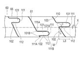
スリット61は、対向して配置される対をなす対向面100,110により構成されており、一方の対向面100には、突出して形成される凸部101が複数形成され、他方の対向面110には、凸部101が入り込む凹部111が複数形成されている。凸部101は、螺旋傾斜角度αに対してスリット61の角度が局所的に変化して段差状に形成される段差部102を備えている。段差部102は、図4に示すように、スリット61の螺旋を解く方向(図4の矢印側から操作をする場合、白抜き矢印を参照)へ基端シャフト60が捩れる際に、段差部102と対向して配置される当接部112と当接し、過度な捩れを抑制する役割を果たす。すなわち、段差部102は、凸部101に形成された螺旋傾斜角度αに対してスリット61の角度が局所的に変化して段差状に形成されている部分であり、かつ、スリット61を有する基端シャフト60(管状体)を螺旋を解く方向に捩じった際に凹部111と当接する部分である。また、図5のように図4と逆向きのスリット170を形成してもよい。その場合、スリット170の螺旋を解く方向は図4と逆方向になる。
The
そして、段差部102の軸心方向Xへの長さL1〜L3は、図2,3に示すように、スリット61のピッチが相対的に大きい部位において、小さい部位よりも長く形成される。したがって、第1柔軟部64よりもスリット61のピッチが広い第2柔軟部65に設けられる段差部102の長さL2は、第1柔軟部64に形成される段差部102の長さL1よりも長い。また、第2柔軟部65よりもスリット61のピッチが広い第3柔軟部66に設けられる段差部102の長さL3は、第2柔軟部65に形成される段差部102の長さL2よりも長い。そして、ピッチが基端方向へ向かって徐々に広くなる第3柔軟部66に設けられる段差部102の長さL3は、基端側の段差部102ほど長くなっている。すなわち、ピッチが広く螺旋傾斜角度αが大きくなる部位に設けられる段差部102ほど、段差部102の長さL1〜L3が長くなっている。ピッチが広く螺旋傾斜角度αが大きい部位ほど、図8に示す比較例ように、凸部160が凹部161から完全に離脱して元の位置に戻り難くなるのに対し、本実施形態では、螺旋傾斜角度αが大きくなる部位に設けられる段差部102ほど、段差部102の長さL1〜L3を長くすることで、螺旋傾斜角度αの程度に応じて、凸部101を凹部111から離脱し難くすることができる。ここで、段差部102の軸心方向Xへの長さは、凸部101と接する軸心方向Xと直交する直線と、螺旋傾斜角度αを有するスリット61の対向面100上でスリット角度が局所的に変化する部位を通る軸心方向Xと直交する直線との間の距離をいう。
And the length L1-L3 to the axial direction X of the level | step-
また、凸部101は、突出方向の先端部において、突出方向へ向かって幅が減少している。このため、凸部101が、凹部111から抜ける方向へ移動できるとともに凹部111に対して元の位置へ戻ることができ、基端シャフト60の曲げ剛性が局所的に大きくなることを抑制して、良好な柔軟性を提供できる。
In addition, the
また、段差部102は、スリット61の角度の局所的な変化量βが90度を超えることが好ましい。具体的には、螺旋傾斜角度αを有するスリット61の対向面100に対する、凸部61の段差部102が形成する角度が90度を超えるように形成することが好ましい。このように構成することで、スリット61の螺旋を解く方向へ基端シャフト60が捩れる際に、図4に示すように、凸部101に設けられる段差部102が凹部111に設けられる当接部112に引っ掛かりやすくなり、過度の捩れをより確実に抑制できる。また、螺旋を解く方向へ基端シャフト60を捩じった際に、凸部101が凹部102から抜けるのを抑制できる。この際、より確実に上述の効果を発揮するために、螺旋傾斜角度αを有するスリット61の対向面110に対する、凸部61の当接部112が形成する角度が90度を超えないように形成することが好ましい。なお、スリット61の角度の局所的な変化量βは、90度を超えていなくてもよい。
Further, in the
また、段差部102は、軸心方向Xと略平行となるように形成されており、軸心方向Xに対する傾斜角度θが少なくとも±5度以内であることがより好ましい。段差部102が軸心方向Xと±5度以内で略平行となることで、基端シャフト60が湾曲する際に凸状に湾曲する側、すなわちスリット61の隙間の幅が広がる側に設けられる凸部101が、凹部111内を移動して容易に離れることができるとともに凹部111に対して元の位置へ戻りやすくなる。このため、凸部101が凹部111から離れることができずに基端シャフト60の曲げ剛性が局所的に大きくなることを抑制でき、良好な柔軟性を提供できる。また、スリット61の隙間の幅が広がる側に設けられる凸部101が凹部111内を移動して容易に離れやすいという点から、段差部102は軸心方向Xに平行となるように形成されていることがよりさらに好ましい。なお、段差部102は、軸心方向Xに対する傾斜角度θが±5度以内でなくてもよい。
Further, the stepped
また、スリット61は、スリット61の隙間の幅が一定に形成されている、すなわち、スリットの対向面100、110の間の幅が一定であることが好ましい。そのように構成することで、凸部101と凹部111の外郭の形状がほぼ同一となる。そのため、スリット61の螺旋を解く方向へ基端シャフト60が捩れる際に、図4に示すように、凸部101に設けられる段差部102が凹部111に設けられる当接部112に引っ掛かりやすくなり、過度の捩れをより確実に抑制できる。また、螺旋を解く方向へ基端シャフト60を捩じった際に、凸部101が凹部102から抜けるのを抑制できる。
Moreover, it is preferable that the
また、螺旋を描くことで軸心方向Xに並んで隣接する各々のスリット61に設けられる段差部102は、基端シャフト60の周方向における位置が異なり、隣接する段差部102同士が軸心方向Xに重ならない。具体的には、少なくとも連続する2つの隣接する段差部102同士が軸心方向Xに重ならない。一例として、段差部102は、螺旋に沿って基端シャフト60の周方向に125度、270度、または450度毎に形成することができる。したがって、基端シャフト60の曲げ剛性が周方向位置に依存して偏らず、良好な柔軟性を提供できる。なお、段差部102は、基端シャフト60の周方向に同一角度毎に形成されなくてもよい。また、全ての段差部102が、基端シャフト60の軸心方向に全く重ならないようにしてもよい。
Moreover, the
また、凸部101は、先端側または基端側のうち、スリット61の螺旋傾斜角度αが大きくなる側、すなわちピッチが広がる側である基端側へ突出して形成されている。このため、スリット61のピッチが変化する部位において、凸部101が延在する方向に凸部101を形成するための十分な長さを確保できる。なお、凸部は、先端側または基端側のうち、スリットのピッチが狭くなる方向へ突出して形成されてもよい。また、凸部の向きは、各凸部によって異なってもよい。
Further, the
そして、スリット61の角度が局所的に変化する部位、すなわち凸部101のエッジの凸状となる角部101Aおよび凹状となる隅部101B、並びに凹部111のエッジの凸状となる角部111Aおよび凹状となる隅部111Bが、曲率を有するように形成されている。このため、レーザー等によりスリット61を形成する際に、前述の角部101A,111Aおよび隅部101B,111Bを加工するためにレーザー等を材料となる管体に対して停止させる必要がなくなり、レーザー等を管体に対して常に移動させながら形成することができる。そのため、角部101A,111Aおよび隅部101B,111Bにレーザー加工により発生した熱が不要に入らず、管体の材料に変質や変形が起こるのを抑制できる。また、角部101A,111Aおよび隅部101B,111Bが曲率を有して形成されることで、鋭利なエッジがなくなり、安全性が向上する。
And the part where the angle of the
基端シャフト60には比較的剛性の高い材質、例えばNi−Ti、真鍮、SUS、アルミ等の金属を用いることが好ましい。なお、比較的剛性の高い材質であれば、ポリイミド、塩化ビニル、ポリカーボネート等の樹脂を用いることもできる。
The
基端シャフト60の高剛性部63は、寸法は特に限定されないが、外径が約0.5mm〜3.5mm、肉厚が約10μm〜170μm、長さが約1100mm〜1400mmの管体である。
The dimension of the high-rigidity portion 63 of the
基端シャフト60の第1柔軟部64は、寸法は特に限定されないが、外径が約0.5mm〜3.5mm、肉厚が約10μm〜170μm、ピッチは約0.1mm〜0.5mmである。
The dimensions of the first flexible portion 64 of the
基端シャフト60の第2柔軟部65は、寸法は特に限定されないが、外径が約0.5mm〜3.5mm、肉厚が約10μm〜170μm、ピッチは約0.5mm〜1.5mmである。
The dimensions of the second flexible portion 65 of the
基端シャフト60の第3柔軟部66は、寸法は特に限定されないが、外径が約0.5mm〜3.5mm、肉厚が約10μm〜170μm、ピッチは約1.5mm〜5.0mmである。
The dimensions of the third
スリット61の隙間の幅は、特に限定されないが、約0.01mm〜0.05mmである。
The width of the gap of the
先端シャフト80、内管シャフト90および中間シャフト70を構成する材料としては、特に限定されないが、例えばポリオレフィン(例えば、ポリエチレン、ポリプロピレン、ポリブテン、エチレン−プロピレン共重合体、エチレン−酢酸ビニル共重合体、アイオノマー、またはこれら二種以上の混合物など)、ポリオレフィンの架橋体、ポリ塩化ビニル、ポリアミド、ポリアミドエラストマー、ポリエステル、ポリエステルエラストマー、ポリウレタン、ポリウレタンエラストマー、フッ素樹脂、ポリイミドなどの高分子材料またはこれらの混合物などを用いることができる。
Although it does not specifically limit as a material which comprises the
先端シャフト80および中間シャフト70は、特に限定されないが、外径が0.7mm〜1.7mm、肉厚が25mm〜200μmの管体である。中間シャフト70の長さは、特に限定されないが、100mm〜150mmである。先端シャフト80の長さは、特に限定されないが、230mm〜250mmである。
The
内管シャフト90は、図1に示すように、先端シャフト80及びバルーン30の内部を同軸状に貫通している。内管シャフト90の先端部は、バルーン30の先端より延長されており、バルーン30の先端側と液密を保った状態で接合されている。一方、内管シャフト90の基端は、中間シャフト70の外周方向における一部(側面に形成された側口)に液密を保った状態で固着されており、この内管シャフト90の基端開口が中間シャフト70の外部に露出して、ガイドワイヤ開口部71を構成している。この内管シャフト90の先端からガイドワイヤ開口部71にかけての内部空間がガイドワイヤルーメン91となっており、ガイドワイヤは内管シャフト90の先端開口を入口とし、ガイドワイヤ開口部71を出口として、内管シャフト90内に挿通される。なお、ガイドワイヤ開口部71は、中間シャフト70ではなく、基端シャフト60または先端シャフト80に設けてもよく、また中間シャフト70と先端シャフト80の境界部(接合部)に設けてもよい。
As shown in FIG. 1, the
バルーン30の内部の内管シャフト90周囲には、X線を用いて造影できるように造影マーカー92が設けられている。
造影マーカー92は、コイルスプリングまたはリングで形成することが好ましく、1個以上設けることができる。造影マーカー92の材質としては、X線造影性の高い材料、例えばPt、Pt合金、W、W合金、Au、Au合金、Ir、Ir合金、Ag、Ag合金などを用いることが好ましい。A
The
ハブ40は、カテーテル本体部20の拡張用ルーメンと連通して拡張用流体を流入出させるポートとして機能する基端開口部41を備えており、基端シャフト60と液密を保った状態で固定されている。
The
ハブ40の構成材料としては、例えば、ABS樹脂、ポリカーボネート、ポリアミド、ポリサルホン、ポリアリレート、メタクリレート−ブチレン−スチレン共重合体等の熱可塑性樹脂が好適に使用できる。また、これらの材料を任意に組み合わせたものを用いてもよい。
As a constituent material of the
耐キンクチューブ50は、ハブ40の先端付近における基端シャフト60のキンク(折れ曲がり)を防止するために、基端シャフト60の外側に載置されている。
The kink
バルーン30は、拡張することで狭窄部を押し広げるものであり、または、バルーン30の外周にステントが配置された場合には、ステントを押し広げるものであり、所定の範囲を効率よく押し広げられるよう、軸方向中央部に略円筒状で形成されてほぼ同一径の筒状部31を有している。バルーン30の筒状部31の先端側には、先端側へ向かって径がテーパ状に縮小して形成される第1の縮径部32が設けられ、基端側には、基端側へ向かって径がテーパ状に縮小して形成される第2の縮径部33が設けられている。
The
第1の縮径部32の先端側は、内管シャフト90の外壁面に液密を保った状態で接合されており、第2の縮径部33の基端側は、先端シャフト80の先端部の外壁面に液密を保った状態で接合されている。したがって、バルーン30の内部は、カテーテル本体部20に形成される拡張用ルーメンと連通し、この拡張用ルーメンを介して、基端側から拡張用流体を流入可能となっている。バルーン30は、拡張用流体の流入により拡張し、流入した拡張用流体を排出することにより折り畳まれた状態となる。
The distal end side of the first reduced
拡張用流体は、気体でも液体でもよく、例えば、空気、ヘリウムガス、CO2ガス、O2ガス等の気体や、生理食塩水、造影剤等の液体が挙げられる。The expansion fluid may be gas or liquid, and examples thereof include gas such as air, helium gas, CO 2 gas, and O 2 gas, and liquid such as physiological saline and contrast medium.
バルーン30は、ある程度の可撓性を有する材料により形成されることが好ましく、そのような材料としては、例えば、ポリエチレン、ポリプロピレン、ポリブテン、エチレン−プロピレン共重合体、エチレン−酢酸ビニル共重合体、アイオノマー、あるいはこれら二種以上の混合物等のポリオレフィンや、軟質ポリ塩化ビニル樹脂、ポリアミド、ポリアミドエラストマー、ポリエステル、ポリエステルエラストマー、ポリウレタン、フッ素樹脂等の熱可塑性樹脂、シリコーンゴム、ラテックスゴム等が使用できる。
The
バルーン30は、寸法は特に限定されないが、拡張されたときの筒状部31の外径が1.0mm〜15.0mm、長さが5mm〜50mmであり、全体の長さが10mm〜90mmである。
The size of the
次に、本実施形態に係るバルーンカテーテル10の使用方法を、血管に挿入して使用する場合を例として説明する。
Next, the method for using the
まず、血管の狭窄部を治療する前に、バルーン30および拡張用ルーメン内の空気をできる限り抜き取り、バルーン30および拡張用ルーメン内を拡張用流体に置換しておく。このとき、バルーン30は、折り畳まれた状態となっている。
First, before treating the stenosis of the blood vessel, the air in the
次に、患者の血管に、例えばセルジンガー法によりシースを留置し、ガイドワイヤルーメン91内にガイドワイヤを挿通させた状態で、ガイドワイヤおよびバルーンカテーテル10をシースの内部より血管内へ挿入する。続いて、ガイドワイヤを先行させつつバルーンカテーテル10を進行させ、バルーン30を狭窄部へ到達させる。
Next, the sheath is placed in the patient's blood vessel by, for example, the Seldinger method, and the guide wire and the
次に、バルーン30が狭窄部に位置した状態で、ハブ40の基端開口部41より、インデフレーター、シリンジ、またはポンプ等を用いて拡張用流体を所定量注入し、拡張用ルーメンを通じてバルーン30の内部に拡張用流体を送り込み、折り畳まれたバルーン30を拡張させる。これにより、バルーン30の筒状部31が、狭窄部を押し広げることができる。また、バルーン30の外周にステントを配置したステントデリバリーシステムとして使用すれば、ステントを塑性変形させながら押し広げ、狭窄部をステントによって押し広げた状態で良好に維持することができる。
Next, in a state where the
この後、拡張用流体を基端開口部41より吸引して排出し、バルーン30を収縮させて折り畳まれた状態とする。なお、ステントデリバリーシステムとして用いた場合には、ステントは拡開した状態のまま狭窄部に留置される。この後、シースを介して血管よりガイドワイヤおよびカテーテル本体部20を抜去し、手技が終了する。
Thereafter, the expansion fluid is sucked and discharged from the
以上のように、本実施形態に係るバルーンカテーテル10は、スリット61の螺旋傾斜角度αが異なる部位を備えることで、柔軟性を軸心方向Xの位置によって任意に設定して操作性を向上できる。そして、スリット61を構成する対をなす対向面100,110の一方の対向面100に、螺旋傾斜角度αに対する角度が局所的に変化する段差部102が形成され、他方の対向面110に、スリット61の螺旋を解く方向へ基端シャフト60が捩れた際に段差部102が当接する当接部112が形成されるため、螺旋を解く方向へ捩れた際に段差部102が当接部112に当接し、スリット61の隙間が開くことが抑制される。さらに、段差部102の軸心方向Xへの長さL1〜L3が、スリット61の螺旋傾斜角度αが相対的に大きい部位において小さい部位よりも長く形成されるため、スリット61の傾斜角度が大きくなることで段差部102の当接部112に対する引っ掛かりが外れやすい部位ほど、段差部102の長さが長くなって当接部112から外れ難くなり、回転方向によるトルク伝達性能の異方性を極力抑えて操作性を向上できる。
As described above, the
また、例えばスリットを構成する対向面を部分的に接続するように、スリットをこま切れ状態とすることでスリットの開きを抑制することもできるが、この場合には、対向面が接続する部位に応力が集中し、材料が疲労して変形や破断、予期しない動作が生じ得る。これに対し、本実施形態では、スリット61が途切れることなく連続して形成されているため、材料の疲労による変形や破断、予期しない動作が抑制される。
In addition, for example, the slit opening can be suppressed by partially cutting the slit so as to partially connect the facing surfaces constituting the slit. Stress can concentrate and the material can fatigue, causing deformation, fracture, and unexpected behavior. On the other hand, in this embodiment, since the
また、螺旋傾斜角度αに対するスリット61の角度の局所的な変化量βが90度を超えるため、スリット61の螺旋を解く方向へ基端シャフト60が捩れる際に、段差部102が当接部112に引っ掛かりやすくなり、過度の捩れをより確実に抑制できる。
Further, since the local change amount β of the angle of the
また、段差部102の軸心方向Xに対する傾斜角度θが±5度以内であるため、段差部102が軸心方向Xと略平行となり、基端シャフト60が湾曲する際に凸状に湾曲する側、すなわちスリット61の幅が広がる必要がある側に設けられる段差部102が、凹部111内で移動できるとともに凹部111に戻りやすくなる。このため、凸部101が凹部111から移動できずに基端シャフト60の曲げ剛性が局所的に大きくなることを抑制でき、良好な柔軟性を提供できる。
Further, since the inclination angle θ of the stepped
また、スリット61の隙間の幅が一定になるため、スリット61を構成する対をなす対向面100,110の一方の対向面100から突出して形成される段差部102と、他方の対向面110に段差部102と当接するように形成された当接部112の形状がほぼ同一となる。このため、スリット61を構成する対をなす対向面100,110の一方から突出して形成される凸部101と、対向面100,110の他方に凸部101が入り込むように形成される凹部111の外郭の形状がほぼ同一となる。このため、スリット61の螺旋を解く方向へ基端シャフト60(管状体)が捩れた際に、凸部101に設けられる段差部102が凹部111に設けられる当接部112に引っ掛かりやすくなり、過度の捩れをより確実に抑制できる。
Further, since the width of the gap of the
また、螺旋を描くことで基端シャフト60(管状体)の軸心方向Xに並んで隣接する各々のスリット61に設けられる段差部102は、基端シャフト60の周方向における位置が異なるため、段差部102が基端シャフト60の軸心方向Xに重ならない。このため、基端シャフト60の曲げ剛性が周方向位置に依存して偏らず、良好な柔軟性を提供できる。
Moreover, since the
また、基端シャフト60(管状体)は、螺旋傾斜角度αが漸次的に変化する部位を有し、当該部位に設けられる複数の段差部102の軸心方向Xへの長さL3が、螺旋傾斜角度αが相対的に小さい部位から大きい部位へ向かって漸次的に長くなるため、基端シャフト60の螺旋傾斜角度αが大きい部位の高い剛性によって十分な押し込み性を確保できるとともに、螺旋傾斜角度αが小さい部位の高い柔軟性によって、生体管腔の湾曲部位等をも容易に通過でき、高い到達性および操作性が得られる。さらに、螺旋傾斜角度αが漸次的に変化することで、曲げ剛性が漸次的に減少しているため、基端シャフト60が急激に曲がる際にも応力が1カ所に集中することがなく、バルーンカテーテル10におけるキンクの発生を低減させることが可能である。
Further, the proximal shaft 60 (tubular body) has a portion where the spiral inclination angle α gradually changes, and the length L3 in the axial direction X of the plurality of
また、基端シャフト60(管状体)は、スリット61を構成する一方の対向面100から突出して形成される凸部101と、他方の対向面110に凸部101が入り込むように形成される凹部111と、を有し、段差部102が、凸部101または凹部111の一部に形成されるため、凸部101が凹部111に入り込むことにより、いずれの回転方向へも過度な捩れを抑制できる。
Further, the proximal shaft 60 (tubular body) includes a
また、凸部101は、先端側または基端側のうち、螺旋傾斜角度αが大きくなる方向である側(本実施形態では基端側)へ突出して形成されているため、螺旋傾斜角度αが変化する部位において、凸部101が延在する方向に凸部101を形成するための十分な長さを確保できる。
Further, since the
また、凸部101は、突出方向へ向かって幅が減少しているため、凸部101が、凹部111から離れることができるとともに凹部111に対して元の位置へ戻ることができ、基端シャフト60の曲げ剛性が局所的に大きくなることを抑制して、良好な柔軟性を提供できる。
Moreover, since the
また、段差部102におけるスリット61の角度が局所的に変化する部位が、曲率を有するように形成されるため、レーザー等によりスリット61を形成する際に、レーザー等を管体に対して停止させずに常に移動させながら形成することができる。そのため、レーザー加工により発生した熱が管体の材料に不要に入り、管体の材料が変質や変形するのを抑制できる。また、曲率を有するように形成されているため、鋭利なエッジがなくなり、安全性が向上する。
In addition, since the portion where the angle of the
なお、本発明は、上述した実施形態のみに限定されるものではなく、本発明の技術的思想内において当業者により種々変更が可能である。例えば、本実施形態では、凸部101に段差部102が形成され、凹部111に当接部112が形成されているが、凸部が突出する方向等の条件によっては、凹部に段差部が形成され、凸部に当接部が形成されることもあり得る。
Note that the present invention is not limited to the above-described embodiments, and various modifications can be made by those skilled in the art within the technical idea of the present invention. For example, in this embodiment, the
また、図6に示す変形例のように、基端シャフト120(管状体)のスリット121に凸部および凹部が形成されずに、段差部131および当該段差部131が当接する当接部141が形成されてもよい。すなわち、基端シャフト120のスリット121を構成する対をなす対向面130,140の一方側の対向面130に、螺旋傾斜角度αに対する角度が局所的に変化する段差部131が形成され、他方側の対向面140に、スリット121の螺旋を解く方向へ基端シャフト120が捩れた際に段差部131が当接する当接部141が形成される。そして、段差部131の軸心方向Xへの長さL4が、螺旋傾斜角度αが相対的に大きい部位において小さい部位よりも長く形成されている。このような構造であっても、基端シャフト120が螺旋を解く方向へ捩れた際に段差部131が当接部141に当接し、スリット121の隙間が開くことが抑制されるとともに、スリット61の螺旋傾斜角度αが相対的に大きい部位において小さい部位よりも長く形成される段差部131によって、回転方向によるトルク伝達性能の異方性を極力抑えて操作性を向上できる。
Further, as in the modification shown in FIG. 6, the stepped
また、本実施形態に係る医療用長尺体は、バルーンカテーテル10であるが、医療用の長尺体であれば特に限定されず、マイクロカテーテルやイメージングカテーテル等の他の用途のカテーテルや、図7に示すようなガイドワイヤ150等であってもよい。ガイドワイヤ150は、螺旋状のスリット153が形成された管状体151と、管状体151に被覆されるポリマー等からなる被覆層152とを備える。なお、ガイドワイヤの構成も、管状体を備えるのであれば、特に限定されない。
The medical long body according to the present embodiment is the
また、本実施形態に係る医療用長尺体は、基端シャフト60(管状体)が、スリット61の螺旋傾斜角度αが異なる3つの第1柔軟部64,第2柔軟部65,および第3柔軟部66を備えているが、螺旋傾斜角度αが異なる部位が存在するのであれば、構成は限定されない。したがって、例えば第3柔軟部66のようなスリット61の螺旋傾斜角度αが漸次的に変化する部位がなくてもよく、または、第3柔軟部66のようなスリット61の傾斜角度αが漸次的に変化する部位のみで形成されてもよい。また、本実施形態に係る医療用長尺体は、先端側ほどスリット61の螺旋傾斜角度αが小さくなるが、スリットの螺旋傾斜角度αが異なる部位の位置関係は、特に限定されず、例えば先端側ほど螺旋傾斜角度αが大きくなってもよく、または、螺旋傾斜角度αの大きい部位と小さい部位が交互に配置されてもよい。また、スリットの螺旋の向きは限定されず、または、スリットを複数有する多重螺旋構造であってもよい。また、スリットがシャフト全体にわたって設けられ、全体をポリマーチューブで覆われたものでもよい。
In addition, in the medical long body according to the present embodiment, the proximal shaft 60 (tubular body) has three first flexible portions 64, second flexible portions 65, and third in which the spiral inclination angle α of the
10 バルーンカテーテル(医療用長尺体)、
60,120 基端シャフト(管状体)、
61,121,153,170 スリット、
62 柔軟部、
63 高剛性部、
64 第1柔軟部、
65 第2柔軟部、
66 第3柔軟部、
100,110,130,140 対向面、
101 凸部、
102,131 段差部、
111 凹部、
112,141 当接部、
150 ガイドワイヤ、
α 螺旋傾斜角度、
β 変化量、
θ 傾斜角度、
L1〜L4 段差部の長さ、
X 軸心方向。10 balloon catheter (medical long body),
60, 120 proximal shaft (tubular body),
61, 121, 153, 170 slits,
62 Flexible part,
63 High rigidity part,
64 1st flexible part,
65 second flexible part,
66 Third flexible part,
100, 110, 130, 140 facing surface,
101 convex part,
102, 131 steps,
111 recesses,
112, 141 contact part,
150 guide wire,
α spiral inclination angle,
β change,
θ tilt angle,
L1 to L4 The length of the step,
X axis direction.
Claims (15)
前記管状体は、前記軸心方向と直交する断面に対する前記スリットの螺旋の延在方向の角度である螺旋傾斜角度が異なる部位を備えるとともに、前記スリットを構成する対をなす対向面の一方側に、前記螺旋傾斜角度に対して前記スリットの角度が局所的に変化する段差部が形成され、前記対向面の他方側に、前記スリットの螺旋を解く方向へ前記管状体が捩れた際に前記段差部が当接する当接部が形成され、
前記段差部の前記軸心方向への長さが、前記螺旋傾斜角度が相対的に大きい部位において小さい部位よりも長くなる医療用長尺体。 A medical elongated body having a tubular body in which a spiral slit is formed at least in part and extends in the axial direction,
The tubular body includes a portion having a different helical inclination angle that is an angle of a spiral extension direction of the slit with respect to a cross section perpendicular to the axial direction, and is provided on one side of a pair of opposing surfaces constituting the slit. A step portion in which the angle of the slit is locally changed with respect to the spiral inclination angle is formed, and the step is formed when the tubular body is twisted in the direction of unscrewing the slit on the other side of the facing surface. A contact portion is formed on which the portion contacts,
A medical long body in which a length of the stepped portion in the axial direction is longer than a small portion at a portion where the spiral inclination angle is relatively large.
前記段差部は、前記凸部または凹部の一部に形成される請求項1〜6のいずれか1項に記載の医療用長尺体。 The tubular body has a convex portion formed to protrude from one of the opposing surfaces forming a pair constituting the slit, and a concave portion formed so that the convex portion enters the other of the opposing surfaces,
The medical long body according to any one of claims 1 to 6, wherein the step portion is formed on a part of the convex portion or the concave portion.
前記管状体は、前記軸心方向と直交する断面に対する前記スリットの螺旋の延在方向の角度である螺旋傾斜角度が異なる部位を備えるとともに、前記スリットを構成する対をなす対向面の一方側に、前記螺旋傾斜角度に対して前記スリットの角度が局所的に変化する段差部が形成され、前記対向面の他方側に、前記スリットの螺旋を解く方向へ前記管状体が捩れた際に前記段差部が当接する当接部が形成され、
前記段差部が、前記管状体の軸心方向と平行であり、
前記段差部の前記軸心方向への長さが、前記螺旋傾斜角度が相対的に大きい部位において小さい部位よりも長くなる、医療用長尺体。 A medical elongated body having a tubular body in which a spiral slit is formed at least in part and extends in the axial direction,
The tubular body includes a portion having a different helical inclination angle that is an angle of a spiral extension direction of the slit with respect to a cross section perpendicular to the axial direction, and is provided on one side of a pair of opposing surfaces constituting the slit. A step portion in which the angle of the slit is locally changed with respect to the spiral inclination angle is formed, and the step is formed when the tubular body is twisted in the direction of unscrewing the slit on the other side of the facing surface. A contact portion is formed on which the portion contacts,
The step portion is Ri parallel der the axial direction of the tubular body,
A medical long body in which a length of the stepped portion in the axial direction is longer than a small portion at a portion where the spiral inclination angle is relatively large .
前記段差部は、前記凸部または凹部の一部に形成される請求項11〜14のいずれか1項に記載の医療用長尺体。 The tubular body has a convex portion formed to protrude from one of the opposing surfaces forming a pair constituting the slit, and a concave portion formed so that the convex portion enters the other of the opposing surfaces,
The medical long body according to any one of claims 1 to 14 , wherein the stepped portion is formed in a part of the convex portion or the concave portion.
Applications Claiming Priority (1)
| Application Number | Priority Date | Filing Date | Title |
|---|---|---|---|
| PCT/JP2013/062358 WO2014174661A1 (en) | 2013-04-26 | 2013-04-26 | Medical elongated body |
Publications (2)
| Publication Number | Publication Date |
|---|---|
| JP6077646B2 true JP6077646B2 (en) | 2017-02-08 |
| JPWO2014174661A1 JPWO2014174661A1 (en) | 2017-02-23 |
Family
ID=51791266
Family Applications (1)
| Application Number | Title | Priority Date | Filing Date |
|---|---|---|---|
| JP2015513455A Active JP6077646B2 (en) | 2013-04-26 | 2013-04-26 | Medical long body |
Country Status (5)
| Country | Link |
|---|---|
| US (1) | US10335575B2 (en) |
| EP (1) | EP2990071B1 (en) |
| JP (1) | JP6077646B2 (en) |
| CN (1) | CN105142709B (en) |
| WO (1) | WO2014174661A1 (en) |
Families Citing this family (8)
| Publication number | Priority date | Publication date | Assignee | Title |
|---|---|---|---|---|
| NZ742411A (en) | 2016-01-01 | 2024-03-22 | Tractus Vascular Llc | Flexible catheter |
| JP6875374B2 (en) | 2016-03-22 | 2021-05-26 | テルモ株式会社 | Medical long body |
| WO2018016529A1 (en) | 2016-07-20 | 2018-01-25 | テルモ株式会社 | Long medical object |
| JP2019165754A (en) * | 2016-08-16 | 2019-10-03 | テルモ株式会社 | Medical elongated body |
| JP2019165753A (en) | 2016-08-16 | 2019-10-03 | テルモ株式会社 | Medical elongated body |
| JP6906104B2 (en) * | 2018-05-09 | 2021-07-21 | 朝日インテック株式会社 | Medical tube |
| KR20220050151A (en) * | 2019-08-15 | 2022-04-22 | 아우리스 헬스, 인코포레이티드 | Medical device having multiple bend sections |
| WO2023192367A1 (en) * | 2022-03-30 | 2023-10-05 | Orbusneich Medical Pte. Ltd. | Multi-filar catheter body construction |
Citations (5)
| Publication number | Priority date | Publication date | Assignee | Title |
|---|---|---|---|---|
| JPH11509752A (en) * | 1995-07-18 | 1999-08-31 | エドワーズ,ガーランド,ユー. | Flexible shaft |
| JP2000197704A (en) * | 1998-10-27 | 2000-07-18 | Terumo Corp | Medical tube and manufacture thereof |
| US6273876B1 (en) * | 1997-12-05 | 2001-08-14 | Intratherapeutics, Inc. | Catheter segments having circumferential supports with axial projection |
| JP2005511259A (en) * | 2001-12-03 | 2005-04-28 | ボストン サイエンティフィック リミテッド | High torque guide wire |
| US20110251519A1 (en) * | 2010-04-09 | 2011-10-13 | Alexandre Romoscanu | Variable stiffness steering mechanism for catheters |
Family Cites Families (3)
| Publication number | Priority date | Publication date | Assignee | Title |
|---|---|---|---|---|
| US8657845B2 (en) | 2007-05-15 | 2014-02-25 | Cook Medical Technologies Llc | Multifilar cable catheter |
| US8696695B2 (en) * | 2009-04-28 | 2014-04-15 | Avinger, Inc. | Guidewire positioning catheter |
| JP5399301B2 (en) * | 2010-03-12 | 2014-01-29 | テルモ株式会社 | catheter |
-
2013
- 2013-04-26 EP EP13883257.1A patent/EP2990071B1/en active Active
- 2013-04-26 JP JP2015513455A patent/JP6077646B2/en active Active
- 2013-04-26 CN CN201380076005.6A patent/CN105142709B/en active Active
- 2013-04-26 WO PCT/JP2013/062358 patent/WO2014174661A1/en active Application Filing
-
2015
- 2015-10-23 US US14/921,397 patent/US10335575B2/en active Active
Patent Citations (5)
| Publication number | Priority date | Publication date | Assignee | Title |
|---|---|---|---|---|
| JPH11509752A (en) * | 1995-07-18 | 1999-08-31 | エドワーズ,ガーランド,ユー. | Flexible shaft |
| US6273876B1 (en) * | 1997-12-05 | 2001-08-14 | Intratherapeutics, Inc. | Catheter segments having circumferential supports with axial projection |
| JP2000197704A (en) * | 1998-10-27 | 2000-07-18 | Terumo Corp | Medical tube and manufacture thereof |
| JP2005511259A (en) * | 2001-12-03 | 2005-04-28 | ボストン サイエンティフィック リミテッド | High torque guide wire |
| US20110251519A1 (en) * | 2010-04-09 | 2011-10-13 | Alexandre Romoscanu | Variable stiffness steering mechanism for catheters |
Also Published As
| Publication number | Publication date |
|---|---|
| EP2990071A1 (en) | 2016-03-02 |
| EP2990071B1 (en) | 2020-01-22 |
| WO2014174661A1 (en) | 2014-10-30 |
| JPWO2014174661A1 (en) | 2017-02-23 |
| CN105142709B (en) | 2018-04-03 |
| CN105142709A (en) | 2015-12-09 |
| US10335575B2 (en) | 2019-07-02 |
| EP2990071A4 (en) | 2017-02-22 |
| US20160082225A1 (en) | 2016-03-24 |
Similar Documents
| Publication | Publication Date | Title |
|---|---|---|
| JP6077646B2 (en) | Medical long body | |
| JP7018423B2 (en) | Vascular reinsertion catheter | |
| US10363392B2 (en) | Deflectable guide | |
| US20220305237A1 (en) | Radial and trans-endocardial delivery catheter | |
| JP2022116350A (en) | progressive flexibility catheter support frame | |
| US8540695B2 (en) | Catheter | |
| ES2257056T3 (en) | MULTILUMEN CATHETER BASKET WITH REINFORCEMENT. | |
| US20130165873A1 (en) | Methods, devices and systems for treating and/or diagnosis of disorders of the ear, nose and throat | |
| US11819647B2 (en) | Dilator | |
| JP2009539504A (en) | Selective renal intubation and infusion system and method | |
| US20160135827A1 (en) | Subintimal crossing wire guide | |
| US20120065621A1 (en) | Double lumen tubing with improved kinking resistance | |
| JP6031087B2 (en) | Balloon catheter | |
| EP3646916A1 (en) | Catheter, separator, and suction system | |
| KR102599998B1 (en) | Bidirectional arterial cannula | |
| JP6342189B2 (en) | catheter | |
| JP4316252B2 (en) | catheter | |
| US20230285741A1 (en) | Circulatory support device with steerable cannula | |
| JP7148308B2 (en) | balloon catheter | |
| EP4279113A2 (en) | Multi-filar catheter body construction | |
| JP2002291897A (en) | Balloon catheter | |
| JP2017158958A (en) | Guide wire | |
| JP2010051738A (en) | Medical tube |
Legal Events
| Date | Code | Title | Description |
|---|---|---|---|
| TRDD | Decision of grant or rejection written | ||
| A01 | Written decision to grant a patent or to grant a registration (utility model) |
Free format text: JAPANESE INTERMEDIATE CODE: A01 Effective date: 20170105 |
|
| A61 | First payment of annual fees (during grant procedure) |
Free format text: JAPANESE INTERMEDIATE CODE: A61 Effective date: 20170112 |
|
| R150 | Certificate of patent or registration of utility model |
Ref document number: 6077646 Country of ref document: JP Free format text: JAPANESE INTERMEDIATE CODE: R150 |
|
| R250 | Receipt of annual fees |
Free format text: JAPANESE INTERMEDIATE CODE: R250 |
|
| R250 | Receipt of annual fees |
Free format text: JAPANESE INTERMEDIATE CODE: R250 |
|
| R250 | Receipt of annual fees |
Free format text: JAPANESE INTERMEDIATE CODE: R250 |
|
| R250 | Receipt of annual fees |
Free format text: JAPANESE INTERMEDIATE CODE: R250 |
|
| R250 | Receipt of annual fees |
Free format text: JAPANESE INTERMEDIATE CODE: R250 |