JP6077437B2 - Substrate processing apparatus and nozzle cleaning method - Google Patents
Substrate processing apparatus and nozzle cleaning method Download PDFInfo
- Publication number
- JP6077437B2 JP6077437B2 JP2013247813A JP2013247813A JP6077437B2 JP 6077437 B2 JP6077437 B2 JP 6077437B2 JP 2013247813 A JP2013247813 A JP 2013247813A JP 2013247813 A JP2013247813 A JP 2013247813A JP 6077437 B2 JP6077437 B2 JP 6077437B2
- Authority
- JP
- Japan
- Prior art keywords
- nozzle
- cleaning
- tank
- liquid
- overflow
- Prior art date
- Legal status (The legal status is an assumption and is not a legal conclusion. Google has not performed a legal analysis and makes no representation as to the accuracy of the status listed.)
- Active
Links
- 238000004140 cleaning Methods 0.000 title claims description 342
- 239000000758 substrate Substances 0.000 title claims description 149
- 238000000034 method Methods 0.000 title claims description 104
- 239000007788 liquid Substances 0.000 claims description 179
- 230000008569 process Effects 0.000 claims description 95
- 230000007246 mechanism Effects 0.000 claims description 40
- 230000002093 peripheral effect Effects 0.000 claims description 37
- XLYOFNOQVPJJNP-UHFFFAOYSA-N water Substances O XLYOFNOQVPJJNP-UHFFFAOYSA-N 0.000 claims description 25
- 238000007599 discharging Methods 0.000 claims description 20
- 238000005406 washing Methods 0.000 claims description 7
- 230000007423 decrease Effects 0.000 claims description 6
- 238000007654 immersion Methods 0.000 claims 2
- 238000010586 diagram Methods 0.000 description 50
- KFZMGEQAYNKOFK-UHFFFAOYSA-N Isopropanol Chemical compound CC(C)O KFZMGEQAYNKOFK-UHFFFAOYSA-N 0.000 description 48
- 238000011084 recovery Methods 0.000 description 43
- 230000003028 elevating effect Effects 0.000 description 22
- 239000000126 substance Substances 0.000 description 11
- 230000004048 modification Effects 0.000 description 9
- 238000012986 modification Methods 0.000 description 9
- 230000032258 transport Effects 0.000 description 5
- 238000005192 partition Methods 0.000 description 4
- KRHYYFGTRYWZRS-UHFFFAOYSA-N Fluorane Chemical compound F KRHYYFGTRYWZRS-UHFFFAOYSA-N 0.000 description 2
- 239000002253 acid Substances 0.000 description 2
- 230000009471 action Effects 0.000 description 2
- 239000000356 contaminant Substances 0.000 description 2
- 238000001035 drying Methods 0.000 description 2
- 239000000428 dust Substances 0.000 description 2
- 238000007781 pre-processing Methods 0.000 description 2
- 238000005507 spraying Methods 0.000 description 2
- 230000002378 acidificating effect Effects 0.000 description 1
- 239000000969 carrier Substances 0.000 description 1
- 230000008859 change Effects 0.000 description 1
- 230000006866 deterioration Effects 0.000 description 1
- 230000000694 effects Effects 0.000 description 1
- 230000037406 food intake Effects 0.000 description 1
- 239000011521 glass Substances 0.000 description 1
- 238000011086 high cleaning Methods 0.000 description 1
- 230000003287 optical effect Effects 0.000 description 1
- 239000004065 semiconductor Substances 0.000 description 1
- 238000009751 slip forming Methods 0.000 description 1
Images


Classifications
-
- B—PERFORMING OPERATIONS; TRANSPORTING
- B05—SPRAYING OR ATOMISING IN GENERAL; APPLYING FLUENT MATERIALS TO SURFACES, IN GENERAL
- B05B—SPRAYING APPARATUS; ATOMISING APPARATUS; NOZZLES
- B05B15/00—Details of spraying plant or spraying apparatus not otherwise provided for; Accessories
- B05B15/50—Arrangements for cleaning; Arrangements for preventing deposits, drying-out or blockage; Arrangements for detecting improper discharge caused by the presence of foreign matter
- B05B15/55—Arrangements for cleaning; Arrangements for preventing deposits, drying-out or blockage; Arrangements for detecting improper discharge caused by the presence of foreign matter using cleaning fluids
- B05B15/555—Arrangements for cleaning; Arrangements for preventing deposits, drying-out or blockage; Arrangements for detecting improper discharge caused by the presence of foreign matter using cleaning fluids discharged by cleaning nozzles
-
- C—CHEMISTRY; METALLURGY
- C03—GLASS; MINERAL OR SLAG WOOL
- C03C—CHEMICAL COMPOSITION OF GLASSES, GLAZES OR VITREOUS ENAMELS; SURFACE TREATMENT OF GLASS; SURFACE TREATMENT OF FIBRES OR FILAMENTS MADE FROM GLASS, MINERALS OR SLAGS; JOINING GLASS TO GLASS OR OTHER MATERIALS
- C03C23/00—Other surface treatment of glass not in the form of fibres or filaments
- C03C23/0075—Cleaning of glass
-
- H—ELECTRICITY
- H01—ELECTRIC ELEMENTS
- H01L—SEMICONDUCTOR DEVICES NOT COVERED BY CLASS H10
- H01L21/00—Processes or apparatus adapted for the manufacture or treatment of semiconductor or solid state devices or of parts thereof
- H01L21/67—Apparatus specially adapted for handling semiconductor or electric solid state devices during manufacture or treatment thereof; Apparatus specially adapted for handling wafers during manufacture or treatment of semiconductor or electric solid state devices or components ; Apparatus not specifically provided for elsewhere
- H01L21/67005—Apparatus not specifically provided for elsewhere
- H01L21/67011—Apparatus for manufacture or treatment
- H01L21/67017—Apparatus for fluid treatment
- H01L21/67028—Apparatus for fluid treatment for cleaning followed by drying, rinsing, stripping, blasting or the like
- H01L21/6704—Apparatus for fluid treatment for cleaning followed by drying, rinsing, stripping, blasting or the like for wet cleaning or washing
- H01L21/67051—Apparatus for fluid treatment for cleaning followed by drying, rinsing, stripping, blasting or the like for wet cleaning or washing using mainly spraying means, e.g. nozzles
-
- H—ELECTRICITY
- H01—ELECTRIC ELEMENTS
- H01L—SEMICONDUCTOR DEVICES NOT COVERED BY CLASS H10
- H01L21/00—Processes or apparatus adapted for the manufacture or treatment of semiconductor or solid state devices or of parts thereof
- H01L21/67—Apparatus specially adapted for handling semiconductor or electric solid state devices during manufacture or treatment thereof; Apparatus specially adapted for handling wafers during manufacture or treatment of semiconductor or electric solid state devices or components ; Apparatus not specifically provided for elsewhere
- H01L21/67005—Apparatus not specifically provided for elsewhere
- H01L21/67011—Apparatus for manufacture or treatment
- H01L21/6715—Apparatus for applying a liquid, a resin, an ink or the like
Description
開示の実施形態は、基板処理装置およびノズル洗浄方法に関する。 The disclosed embodiment relates to a substrate processing apparatus and a nozzle cleaning method.
従来、半導体ウエハやガラス基板等の基板に対して処理液を供給することによって基板を処理する基板処理装置が知られている。 2. Description of the Related Art Conventionally, a substrate processing apparatus that processes a substrate by supplying a processing liquid to a substrate such as a semiconductor wafer or a glass substrate is known.
このような基板処理装置においては、処理液を吐出するノズル自体に吐出した後の処理液が付着するおそれがあり、かかる処理液が汚染物質となってノズルに残存するおそれがある。このようにノズルが汚れた状態で基板処理を行うと、ノズルに付着した汚染物質が基板に飛散して基板が汚損されるおそれがある。このため、基板処理装置には、ノズルの洗浄装置が設けられる場合がある。 In such a substrate processing apparatus, there is a possibility that the processing liquid after being discharged onto the nozzle itself that discharges the processing liquid may adhere, and such a processing liquid may become a contaminant and remain on the nozzle. When the substrate processing is performed in such a state where the nozzle is dirty, there is a possibility that the contaminant attached to the nozzle is scattered on the substrate and the substrate is damaged. For this reason, the substrate processing apparatus may be provided with a nozzle cleaning device.
たとえば、特許文献1には、ノズルに対して洗浄液を吹き付けることによって、ノズルに付着した汚れを除去するノズル洗浄装置が開示されている。 For example, Patent Document 1 discloses a nozzle cleaning device that removes dirt adhered to a nozzle by spraying a cleaning liquid onto the nozzle.
しかしながら、特許文献1に記載の技術のように洗浄液を吹き付ける方式を採った場合、ノズルに洗浄ムラが生じ易いという問題があった。また、ノズル洗浄装置を含む周辺機器を大型化させたくないという要求がある。 However, when the method of spraying the cleaning liquid as in the technique described in Patent Document 1 is employed, there is a problem that cleaning unevenness is likely to occur in the nozzle. In addition, there is a demand not to increase the size of peripheral devices including the nozzle cleaning device.
実施形態の一態様は、洗浄性能を向上させさらに小型化を図ることのできる基板処理装置およびノズル洗浄方法を提供することを目的とする。 An object of one embodiment is to provide a substrate processing apparatus and a nozzle cleaning method capable of improving cleaning performance and further reducing the size.
実施形態の一態様に係る基板処理装置は、基板に第1の処理液を吐出する第1のノズルおよび基板に第2の処理液を吐出する第2のノズルと、第1のノズルおよび第2のノズルを移動させる移動機構と、第1のノズルおよび第2のノズルを洗浄するノズル洗浄装置とを備える。ノズル洗浄装置は、洗浄槽と、オーバーフロー槽と、ダミーディスペンス槽とを備える。洗浄槽は、第1のノズルおよび第2のノズルを洗浄するための洗浄液を貯留する貯留部と、所定の水位を超えた洗浄液を貯留部から排出するオーバーフロー部とを備える。オーバーフロー槽は、洗浄槽に隣接して配置され、オーバーフロー部から排出される洗浄液を受けて外部へ排出する。ダミーディスペンス槽は、第1のノズルから吐出される前記第1の処理液を受けて外部へ排出する。オーバーフロー槽は、第1のノズルが貯留部内に配置された場合に第2のノズルが配置される位置に設けられる。そして、第1のノズルおよび第2のノズルを洗浄する場合には、第1のノズルおよび第2のノズルを洗浄槽の貯留部内で洗浄液に浸漬させ、第1のノズルから第1の処理液を吐出させるダミーディスペンス処理を行う場合には、ダミーディスペンス槽内へ第1のノズルから第1の処理液を吐出させ、第2のノズルから第2の処理液を吐出させるダミーディスペンス処理を行う場合には、オーバーフロー槽内へ第2のノズルから第2の処理液を吐出させる。 Exemplary substrate processing apparatus according to an aspect of the embodiment includes a second nozzle for discharging a second treatment liquid to the first nozzle and the substrate to discharge the first processing solution to the substrate, the first nozzle and the second And a nozzle cleaning device for cleaning the first nozzle and the second nozzle. The nozzle cleaning device includes a cleaning tank, an overflow tank, and a dummy dispensing tank . The cleaning tank includes a storage unit that stores a cleaning liquid for cleaning the first nozzle and the second nozzle, and an overflow unit that discharges the cleaning liquid exceeding a predetermined water level from the storage unit. The overflow tank is disposed adjacent to the cleaning tank, receives the cleaning liquid discharged from the overflow portion, and discharges it to the outside. The dummy dispensing tank receives the first processing liquid discharged from the first nozzle and discharges it to the outside. The overflow tank is provided at a position where the second nozzle is disposed when the first nozzle is disposed in the reservoir. When washing the first nozzle and the second nozzle is immersed in the cleaning liquid in the reservoir portion of the cleaning tank to the first nozzle and the second nozzle, the first treatment liquid from the first nozzle When performing the dummy dispensing process to be discharged, when performing the dummy dispensing process in which the first processing liquid is discharged from the first nozzle into the dummy dispensing tank and the second processing liquid is discharged from the second nozzle . Discharges the second processing liquid from the second nozzle into the overflow tank .
実施形態の一態様によれば、洗浄性能を向上させさらに小型化を図ることができる。 According to one aspect of the embodiment, the cleaning performance can be improved and further downsizing can be achieved.
以下、添付図面を参照して、本願の開示する基板処理装置およびノズル洗浄方法の実施形態を詳細に説明する。なお、以下に示す実施形態によりこの発明が限定されるものではない。 Hereinafter, embodiments of a substrate processing apparatus and a nozzle cleaning method disclosed in the present application will be described in detail with reference to the accompanying drawings. In addition, this invention is not limited by embodiment shown below.
(第1の実施形態)
<1−1.基板処理システムの構成>
まず、第1の実施形態に係る基板処理システムの構成について図1を用いて説明する。図1は、第1の実施形態に係る基板処理システムの構成を示す図である。なお、以下においては、位置関係を明確にするために、互いに直交するX軸、Y軸およびZ軸を規定し、Z軸正方向を鉛直上向き方向とする。
(First embodiment)
<1-1. Configuration of substrate processing system>
First, the configuration of the substrate processing system according to the first embodiment will be described with reference to FIG. FIG. 1 is a diagram illustrating a configuration of a substrate processing system according to the first embodiment. In the following, in order to clarify the positional relationship, the X axis, the Y axis, and the Z axis that are orthogonal to each other are defined, and the positive direction of the Z axis is the vertically upward direction.
図1に示すように、基板処理システム1は、基板搬入出部2と、基板搬送部3と、基板処理部4とを備える。これら基板搬入出部2、基板搬送部3および基板処理部4は、X軸正方向に、基板搬入出部2、基板搬送部3および基板処理部4の順で接続される。
As shown in FIG. 1, the substrate processing system 1 includes a substrate carry-in / out unit 2, a
基板搬入出部2は、基板Wを複数枚(たとえば、25枚)まとめてキャリア21で搬入及び搬出するための処理部である。基板搬入出部2には、たとえば4個のキャリア21が基板搬送部3の前壁31に密着した状態で並べて載置される。
The substrate loading / unloading unit 2 is a processing unit for loading and unloading a plurality of substrates W (for example, 25) by the
基板搬送部3は、基板搬入出部2に隣接して配置され、内部に基板搬送装置32と基板受渡台33とを備える。基板搬送装置32は、キャリア21と基板受渡台33との間で基板Wの搬送を行う。
The
基板処理部4は、基板搬送部3に隣接して配置される。基板処理部4は、基板搬送装置41と複数の基板処理装置42とを備える。基板処理装置42は、基板搬送装置41の移動方向に沿って並べて配置され、基板搬送装置41は、基板受渡台33と基板処理装置42との間で基板Wの搬送を行う。そして、基板処理装置42は、基板搬送装置41によって搬入される基板Wに対して所定の薬液処理を行う。
The
また、基板処理システム1は、制御装置100を備える。制御装置100は、基板処理システム1の動作を制御する装置である。制御装置100は、たとえばコンピュータであり、制御部101と記憶部102とを備える。記憶部102には、後述するノズル洗浄処理やダミーディスペンス処理等の各種の処理を制御するプログラムが格納される。制御部101は記憶部102に記憶されたプログラムを読み出して実行することによって基板処理システム1の動作を制御する。
Further, the substrate processing system 1 includes a
なお、かかるプログラムは、コンピュータによって読み取り可能な記録媒体に記録されていたものであって、その記録媒体から制御装置100の記憶部102にインストールされたものであってもよい。コンピュータによって読み取り可能な記録媒体としては、たとえばハードディスク(HD)、フレキシブルディスク(FD)、コンパクトディスク(CD)、マグネットオプティカルディスク(MO)、メモリカードなどがある。
The program may be recorded on a computer-readable recording medium and may be installed in the
<1−2.基板処理装置の構成>
次に、第1の実施形態に係る基板処理装置42の構成について図2を用いて説明する。図2は、第1の実施形態に係る基板処理装置42の構成を示す模式図である。
<1-2. Configuration of substrate processing apparatus>
Next, the configuration of the
図2に示すように、第1の実施形態に係る基板処理装置42は、処理室11内に、基板保持部12と、ノズルユニット13と、ノズル洗浄装置14とを備える。
As shown in FIG. 2, the
基板保持部12は、回転保持機構121と、処理液回収機構122とを備える。回転保持機構121は、基板Wを水平に保持するとともに、保持した基板Wを鉛直軸まわりに回転させる。処理液回収機構122は、回転保持機構121を取り囲むように配置され、基板Wの回転による遠心力によって基板Wの外方へ飛散する処理液を受け止めて回収する。
The
ノズルユニット13は、回転保持機構121によって保持された基板Wの上方から基板Wへ向けて処理液を供給する。かかるノズルユニット13は、ノズルヘッド131と、ノズルヘッド131を水平に支持するノズルアーム132と、ノズルアーム132を旋回移動および昇降移動させる移動機構133とを備える。
The
ここで、ノズルヘッド131の構成について図3を参照して説明する。図3は、ノズルヘッド131の構成を示す模式図である。
Here, the configuration of the
図3に示すように、ノズルヘッド131は、それぞれ異なる種類の処理液を吐出する3つのノズルを備える。具体的には、ノズルヘッド131は、純水を吐出する第1ノズル134、DHF(希フッ酸)を吐出する第2ノズル135およびIPA(イソプロピルアルコール)を吐出する第3ノズル136を備える。
As shown in FIG. 3, the
第1ノズル134は、バルブ201を介して純水供給源301に接続され、第2ノズル135は、バルブ202を介してDHF供給源302に接続される。また、第3ノズル136は、バルブ203を介してIPA供給源303に接続される。
The
第1ノズル134、第2ノズル135および第3ノズル136は、いずれも鉛直下向きに処理液を吐出する。また、第1ノズル134、第2ノズル135および第3ノズル136は、ノズルアーム132における移動機構133側の基端部からノズルアーム132の延在方向に沿ってノズルヘッド131を見たときに、左から右に第1ノズル134、第2ノズル135および第3ノズル136の順番で並べて配置される。そして、第1ノズル134、第2ノズル135および第3ノズル136は、移動機構133によって一体的に移動することができる。
The
ノズル洗浄装置14は、ノズルユニット13が備えるノズル134〜136を洗浄する装置であり、基板Wの外方におけるノズルユニット13の待機位置に配置される。
The
<1−3.ノズル洗浄装置の構成>
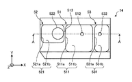
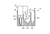
次に、ノズル洗浄装置14の構成について図4および図5を参照して説明する。図4および図5は、第1の実施形態に係るノズル洗浄装置14の構成を示す模式図である。なお、図4にはノズル洗浄装置14の模式平面図を、図5には図4におけるA−A線断面図をそれぞれ示している。
<1-3. Configuration of nozzle cleaning device>
Next, the configuration of the
図4に示すように、ノズル洗浄装置14は、洗浄槽51と、オーバーフロー槽52と、ダミーディスペンス槽53とを備える。これらは、X軸正方向に、オーバーフロー槽52、洗浄槽51およびダミーディスペンス槽53の順で隣接して配置される。
As shown in FIG. 4, the
<1−3−1.洗浄槽>
洗浄槽51は、ノズル134〜136を洗浄する洗浄液を貯留する貯留部511と、貯留部511に貯留された洗浄液を排出する排出口512とを備える。洗浄液は、たとえば常温(たとえば20℃)の純水である。なお、洗浄力を高めるために常温よりも高い所定の温度(45〜80℃程度)に加熱された純水を洗浄液として用いてもよい。
<1-3-1. Washing tank>
The
図5に示すように、貯留部511は、上端部から下端部にかけて一定の内寸を有する第1内周部511aと、第1内周部511aの下端部に上端部が連接し、上端部から下端部に向かうに従って漸次縮径する漏斗状の第2内周部511bとを有する。そして、第2内周部511bの下端部に排出口512が設けられる。
As shown in FIG. 5, the
貯留部511の内部には、貯留部511に洗浄液を供給する洗浄液供給部が設けられる。また、貯留部511の上方には、洗浄後のノズル134〜136を乾燥させるための気体供給部54が設けられる。
A cleaning liquid supply unit that supplies cleaning liquid to the
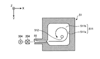
ここで、洗浄液供給部および気体供給部54の構成について図6〜図8を参照して説明する。図6は、洗浄液供給部および気体供給部54の構成を示す模式図である。また、図7は、洗浄液供給部の構成を示す模式図であり、図8は、気体供給部54の構成を示す模式図である。なお、図6には、図5におけるB−B線断面図を示している。
Here, the configuration of the cleaning liquid supply unit and the
図6に示すように、洗浄液供給部55は、貯留部511における第2内周部511bの上端部近傍に設けられる。洗浄液供給部55は、バルブ204を介して洗浄液供給源304に接続されており、洗浄液供給源304から供給される洗浄液をバルブ204を介して貯留部511内へ供給する。
As shown in FIG. 6, the cleaning
洗浄液供給部55は、排出口512から排出される洗浄液よりも多くの洗浄液を貯留部511内へ供給する。したがって、洗浄液供給部55から貯留部511内へ洗浄液が供給されることにより、貯留部511内に洗浄液が貯留される。
The cleaning
図7に示すように、洗浄液供給部55は、たとえば、洗浄槽51を平面視した場合に、第2内周部511bの上端部(第1内周部511aの下端部)の一辺に対し、この辺に隣接する他の辺(ここでは、Y軸正方向側の辺)側に寄せた状態で設けられる。
As shown in FIG. 7, for example, when the
そして、洗浄液供給部55は、平面視において上記他の辺に沿った向きに洗浄液を供給する。これにより、洗浄液供給部55から供給された洗浄液が漏斗状の第2内周部511bを流れて排出口512へ到達する過程で、貯留部511内に洗浄液の旋回流が形成される。
Then, the cleaning
なお、第2内周部511bは、上端部が平面視略矩形状であり、かつ、下端部が平面視円形であって、上端部から下端部に向かうに従って断面形状が略矩形状から円形に滑らかに変化するように形成される。これにより、貯留部511に旋回流を形成し易くすることができる。
The second inner
貯留部511内に旋回流を形成するためには、洗浄液供給部55から供給された洗浄液が結果的に貯留部511の内周面に沿って流れればよい。すなわち、洗浄液供給部55は、少なくとも、平面視において第1内周部511aの中心からずれた位置へ向けて洗浄液を供給する構成であればよく、図6および図7に示した構成に限定されない。
In order to form a swirl flow in the
たとえば、洗浄液供給部55は、洗浄槽51を平面視した場合に第2内周部511bの上端部(第1内周部511aの下端部)の一辺の中央に設けられ、この辺以外の他の辺に対して洗浄液を斜めに供給する構成であってもよい。
For example, the cleaning
ここでは、第1内周部511aが平面視略矩形状である場合の例について示したが、第1内周部511aは、たとえば平面視において円形あるいは楕円形であってもよい。
Here, an example in which the first inner
第2内周部511bは、図5や図6に示すように、偏心した漏斗形状を有しており、第2内周部511bの下端部に形成される排出口512は、図7に示すように、貯留部511を平面視した場合において第1内周部511aの中心からずれた位置に配置される。
As shown in FIGS. 5 and 6, the second inner
このように、排出口512を第1内周部511aの中心からずらして配置することで、排出口512から洗浄液が排出される際に生じる渦の中心位置が、第1内周部511aの中心からずれることとなる。
Thus, by arranging the
これにより、ノズル134〜136の洗浄を行う際に、ノズル134〜136の先端面に空気溜まりが形成されることを防止することができ、ノズル134〜136の先端面の洗浄ムラを抑えることができる。
Thereby, when cleaning the
つづいて、気体供給部54について説明する。図6に示すように、気体供給部54は、貯留部511の上方に設けられる。具体的には、気体供給部54は、洗浄槽51のY軸方向に面する2つの壁面にそれぞれ設けられる。各壁面には、たとえば図5に示すように複数の気体供給部54が水平方向に並べて配置される。
Next, the
気体供給部54は、バルブ205を介して気体供給源305に接続されており、かかる気体供給源305からバルブ205を介して供給されるN2等の気体を水平方向に噴出する。
The
具体的には、図8に示すように、Y軸負方向側の壁面に配置される気体供給部54は、Y軸正方向へ向けて、つまり、Y軸正方向側の壁面へ向けて真っ直ぐに気体を噴出する。一方、Y軸正方向側に配置される気体供給部54は、Y軸負方向に対して斜めに気体を噴出する。
Specifically, as shown in FIG. 8, the
これにより、一方側に配置された気体供給部54から噴出される気体と、他方側に配置された気体供給部54から噴出される気体とが衝突することを防止でき、気体同士が衝突することによる風圧の低下を防止することができる。
Thereby, it can prevent that the gas ejected from the
<1−3−2.オーバーフロー槽およびダミーディスペンス槽>
次に、オーバーフロー槽52およびダミーディスペンス槽53の構成について説明する。まず、オーバーフロー槽52の構成について説明する。
<1-3-2. Overflow tank and dummy dispensing tank>
Next, the configuration of the
図4および図5に示すように、オーバーフロー槽52は、洗浄槽51のX軸負方向側に隣接して配置され、洗浄槽51からオーバーフローした洗浄液を受けて外部へ排出する。かかるオーバーフロー槽52は、貯留部521と、排出口522とを備える。
As shown in FIGS. 4 and 5, the
貯留部521は、図5に示すように、上端部から下端部にかけて一定の内寸を有する第1内周部521aと、第1内周部521aの下端部に上端部が連接し、上端部から下端部に向かうに従って漸次縮径する漏斗状の第2内周部521bとを有する。また、排出口522は、第2内周部521bの下端部に設けられる。
As shown in FIG. 5, the
洗浄槽51のオーバーフロー槽52側の上端部には、オーバーフロー部513が設けられている。オーバーフロー部513は、洗浄槽51の他の上端部よりも低く形成された部位であり、所定の水位を超えた洗浄槽51内の洗浄液、言い換えれば、オーバーフロー部513に達した洗浄液は、かかるオーバーフロー部513からオーバーフロー槽52へ排出される。
An
なお、オーバーフロー槽52の排出口522は、洗浄槽51の排出口512よりも大きく形成される。これにより、洗浄槽51の排出口512を小さく形成することで、貯留部511内に洗浄液を貯留し易くしつつ、ノズル134〜136から除去された汚れをオーバーフロー槽52の大きな排出口522からすぐに排出することができる。
Note that the
つづいて、ダミーディスペンス槽53の構成について説明する。ダミーディスペンス槽53は、洗浄槽51のオーバーフロー槽52が配置される側とは反対側に隣接して配置され、洗浄槽51およびオーバーフロー槽52と同様、貯留部531と、排出口532とを備える。
Next, the configuration of the
図5に示すように、貯留部531は、上端部から下端部にかけて一定の内寸を有する第1内周部531aと、第1内周部531aの下端部に上端部が連接し、上端部から下端部に向かうに従って漸次縮径する漏斗状の第2内周部531bとを有する。排出口532は、第2内周部531bの下端部に設けられる。
As shown in FIG. 5, the
かかるダミーディスペンス槽53は、ダミーディスペンス処理時に第3ノズル136(図3参照)を収容して、第3ノズル136から吐出される処理液(IPA)を受けて排出する。ダミーディスペンス処理とは、たとえば処理液の劣化を防止するために、基板Wに処理液を吐出していない待機中にノズル134〜136から処理液を適宜吐出させる処理のことである。
The
このように、ノズルヘッド131に設けられた3つのノズル134〜136のうち、第3ノズル136のダミーディスペンス処理は、ダミーディスペンス槽53で行われる。
As described above, the dummy dispensing process of the
一方、第1ノズル134および第2ノズル135のダミーディスペンス処理は、オーバーフロー槽52で行われる。このように、オーバーフロー槽52は、第1ノズル134および第2ノズル135用のダミーディスペンス槽としても用いられるが、かかる点については、後述する。
On the other hand, the dummy dispensing process for the
<1−4.ノズル洗浄装置の具体的動作>
<1−4−1.ノズル洗浄処理>
次に、ノズル洗浄装置14の具体的動作について説明する。まず、ノズル洗浄処理の動作について図9A〜図9Gを参照して説明する。図9A〜図9Gは、第1の実施形態に係るノズル洗浄処理の動作例を示す模式図である。
<1-4. Specific operation of the nozzle cleaning device>
<1-4-1. Nozzle cleaning process>
Next, a specific operation of the
なお、図9A〜図9Gに示すノズル洗浄処理は、たとえばロットごとに行われるものとするが、これに限らず、1枚の基板Wに対する基板処理を終えるごとに行われてもよい。 The nozzle cleaning process illustrated in FIGS. 9A to 9G is performed, for example, for each lot, but is not limited thereto, and may be performed every time the substrate process for one substrate W is completed.
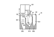
まず、制御部101(図1参照)は、移動機構133(図2参照)を制御してノズルヘッド131を基板W上からノズル洗浄装置14へ移動させて、図9Aに示すように、第1ノズル134および第2ノズル135を洗浄槽51の貯留部511内に配置させる。このとき、第3ノズル136は、ダミーディスペンス槽53内に配置される。
First, the control unit 101 (see FIG. 1) controls the moving mechanism 133 (see FIG. 2) to move the
つづいて、制御部101は、バルブ204(図6参照)を開放することによって、洗浄液供給部55から洗浄槽51の貯留部511内に洗浄液を供給する。これにより、貯留部511内に洗浄液が貯留され、貯留部511内に配置された第1ノズル134および第2ノズル135が、かかる洗浄液に浸漬される(図9B参照)。
Subsequently, the
このように、ノズル洗浄装置14は、貯留部511内に貯留された洗浄液に第1ノズル134および第2ノズル135を浸漬させることによって第1ノズル134および第2ノズル135を洗浄する。これにより、第1ノズル134および第2ノズル135を先端部から上部までムラ無く洗浄することができる。
As described above, the
また、貯留部511内には洗浄液の旋回流が形成されるため、かかる旋回流により、第1ノズル134および第2ノズル135の洗浄力を高めることができる。
Moreover, since the swirling flow of the cleaning liquid is formed in the
貯留部511内の所定の水位を超えた洗浄液は、オーバーフロー部513からオーバーフロー槽52へオーバーフローして、オーバーフロー槽52の排出口522から基板処理装置42の外部へ排出される。
The cleaning liquid that exceeds a predetermined water level in the
バルブ204を開放してから所定時間経過した後、制御部101がバルブ204を閉じることにより、貯留部511内の洗浄液が排出口512から全て排出される。
After a predetermined time has elapsed since the
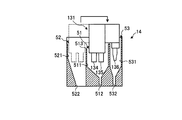
つづいて、制御部101は、移動機構133を制御してノズルヘッド131を移動させて、図9Cに示すように、第3ノズル136を洗浄槽51の貯留部511内に配置させる。このとき、第1ノズル134および第2ノズル135は、オーバーフロー槽52内に配置される。
Subsequently, the
つづいて、制御部101は、バルブ204(図6参照)を開放することによって、洗浄液供給部55から洗浄槽51の貯留部511内に洗浄液を供給する。これにより、貯留部511内に洗浄液が貯留されて、貯留部511内に配置された第3ノズル136が浸漬洗浄される(図9D参照)。
Subsequently, the
バルブ204を開放してから所定時間経過した後、制御部101がバルブ204を閉じることにより、貯留部511内の洗浄液が排出口512から全て排出される。
After a predetermined time has elapsed since the
つづいて、制御部101は、バルブ205(図6参照)を開放することによって気体供給部54から気体を噴出させるとともに、移動機構133を制御してノズルヘッド131を上昇および降下させる(図9E参照)。これにより、第3ノズル136に残存する洗浄液が気体供給部54からの気体によって除去あるいは気化されて、第3ノズル136が乾燥する。
Subsequently, the
つづいて、制御部101は、移動機構133を制御してノズルヘッド131を移動させて、図9Fに示すように、第1ノズル134および第2ノズル135を再び洗浄槽51の貯留部511内に配置させる。そして、制御部101は、移動機構133を制御してノズルヘッド131を上昇および降下させて(図9G参照)、第1ノズル134および第2ノズル135に残存する洗浄液を気体供給部54からの気体によって除去あるいは気化させる。これにより、第1ノズル134および第2ノズル135が乾燥する。
Subsequently, the
その後、制御部101は、バルブ205を閉じて気体供給部54からの気体の供給を停止し、一連のノズル洗浄処理を終える。
Thereafter, the
ノズル洗浄処理後のノズルヘッド131は、ホームポジション、すなわち、第1ノズル134および第2ノズル135が洗浄槽51内に、第3ノズル136がダミーディスペンス槽53内にそれぞれ配置された状態で、次の基板処理が開始されるまで待機する。
The
このように、ノズル洗浄装置14は、洗浄液供給部55から洗浄槽51に洗浄液を供給するとともに、所定の水位を超えた洗浄液をオーバーフロー槽52へオーバーフローさせながら、各ノズル134〜136を浸漬洗浄する。
In this manner, the
これにより、ノズル134〜136から除去された汚れが貯留部511に留まることなくすぐに排出されるため、ノズル134〜136への汚れの再付着を防止することができる。また、貯留部511内に旋回流を継続して形成しておくことができるため、旋回流による高い洗浄力を維持することが可能である。
Thereby, since the dirt removed from the
ここで、制御部101は、ノズルヘッド131をノズル洗浄装置14へ移動させる前に、洗浄液であるHDIWを貯留部511内に供給し、一旦貯留する前処理を行ってもよい。
Here, before moving the
このように、ノズル洗浄装置14は、前処理を行うことで、本処理を行う前に、洗浄液供給源304と洗浄液供給部55とを接続する配管内に残留する温度の下がった純水を排出することができ、本処理時に所定温度の純水を直ちに供給することができる。また、貯留部511に高温の純水を一旦貯留することで貯留部511が温められるため、本処理時において貯留部511内に高温の純水を供給した際に、供給された純水の温度低下を抑えることができる。
As described above, the
<1−4−2.ダミーディスペンス処理>
次に、ダミーディスペンス処理の動作について図10Aおよび図10Bを参照して説明する。図10Aおよび図10Bは、第1の実施形態に係るダミーディスペンス処理の動作例を示す模式図である。図10Aには、第3ノズル136のダミーディスペンス処理の動作例を、図10Bには、第1ノズル134および第2ノズル135のダミーディスペンス処理の動作例をそれぞれ示している。
<1-4-2. Dummy dispensing process>
Next, the operation of the dummy dispensing process will be described with reference to FIGS. 10A and 10B. FIG. 10A and FIG. 10B are schematic diagrams illustrating an operation example of the dummy dispensing process according to the first embodiment. FIG. 10A shows an operation example of the dummy dispensing process of the
なお、図10Aおよび図10Bに示すダミーディスペンス処理は、所定の条件(たとえば、前回のダミーディスペンス処理からの経過時間など)を満たした場合に実行されるものとするが、これに限らず、上述したノズル洗浄処理を終えるごとに実行されてもよい。ノズル洗浄後にダミーディスペンス処理を行うことで、ノズル洗浄処理時にノズル134〜136の内部に入り込んだ洗浄液を次の基板処理の前に排出することができる。
The dummy dispensing process shown in FIGS. 10A and 10B is executed when a predetermined condition (for example, an elapsed time from the previous dummy dispensing process) is satisfied, but is not limited to this. It may be executed every time the nozzle cleaning process is completed. By performing the dummy dispensing process after the nozzle cleaning, the cleaning liquid that has entered the
図10Aに示すように、制御部101は、第3ノズル136のダミーディスペンス処理を行う場合には、移動機構133(図2参照)を制御してノズルヘッド131を移動させて、第3ノズル136をダミーディスペンス槽53内に配置させる。このとき、第1ノズル134および第2ノズル135は、洗浄槽51内に配置される。
As shown in FIG. 10A, when performing the dummy dispensing process for the
そして、制御部101は、バルブ203を所定時間開放して、第3ノズル136から処理液であるIPAを所定時間吐出させる。第3ノズル136から吐出されたIPAは、ダミーディスペンス槽53の排出口532から外部に排出される。
Then, the
一方、第1ノズル134および第2ノズル135のダミーディスペンス処理を行う場合、制御部101は、図10Bに示すように、移動機構133を制御してノズルヘッド131を移動させて、第1ノズル134および第2ノズル135をオーバーフロー槽52内に配置させる。このとき、第3ノズル136は、洗浄槽51内に配置される。
On the other hand, when performing the dummy dispensing process of the
そして、制御部101は、バルブ201およびバルブ202を所定時間開放して、第1ノズル134から純水を、第2ノズル135からDHFをそれぞれ所定時間吐出させる。第1ノズル134から吐出された純水および第2ノズル135から吐出されたDHFは、オーバーフロー槽52の排出口522から外部に排出される。
Then, the
このように、第1の実施形態に係るノズル洗浄装置14では、洗浄槽51からオーバーフローした洗浄液を受けて排出するオーバーフロー槽52を、第1ノズル134および第2ノズル135用のダミーディスペンス槽としても利用することとした。このように、オーバーフロー槽とダミーディスペンス槽とを共用化することにより、ダミーディスペンス槽を別途設けなくてもよいため、ノズル洗浄装置14の小型化を図ることができる。
As described above, in the
また、オーバーフロー槽52をダミーディスペンス槽としても使用することで、ダミーディスペンス処理時にオーバーフロー槽52に付着した処理液を、ノズル洗浄処理時に洗浄槽51からオーバーフローする洗浄液によって除去することができる。つまり、ノズル洗浄処理時に洗浄槽51からオーバーフローする洗浄液をダミーディスペンス槽としてのオーバーフロー槽52を洗浄するための洗浄液としても利用することができる。
Further, by using the
なお、ここでは、オーバーフロー槽52の排出口522を洗浄槽51の排出口512よりも大きく形成することとしたが、オーバーフロー槽52の排出口522を洗浄槽51の排出口512と同程度に小さく形成してもよい。これにより、オーバーフローした洗浄液がオーバーフロー槽52内に貯留し易くなるため、オーバーフローした洗浄液を用いてオーバーフロー槽52のより広い範囲を洗浄することができる。
Here, the
また、第1の実施形態に係るノズル洗浄装置14は、有機系の処理液であるIPAを吐出する第3ノズル136(第1の実施形態における「第1のノズル」の一例に相当)のダミーディスペンス処理を行うためのダミーディスペンス槽53を、その他の処理液を吐出する第1ノズル134および第2ノズル135(第1の実施形態における「第2のノズル」の一例に相当)のダミーディスペンス処理が行われるオーバーフロー槽52とは別に備えることとした。これにより、DHFといった他の薬液とIPAとの混蝕を回避することができる。
Further, the
なお、ここでは、ノズル洗浄処理を終えた後で、ダミーディスペンス処理を行うこととしたが、ダミーディスペンス処理は、ノズル洗浄処理中に行ってもよい。 Here, the dummy dispensing process is performed after the nozzle cleaning process is completed, but the dummy dispensing process may be performed during the nozzle cleaning process.
たとえば、図9Dに示すように、第1ノズル134および第2ノズル135は、第3ノズル136の洗浄中においてオーバーフロー槽52内に配置される。そこで、第3ノズル136の洗浄中に、第1ノズル134および第2ノズル135のダミーディスペンス処理を行ってもよい。
For example, as shown in FIG. 9D, the
また、図9Fに示すように、第1ノズル134および第2ノズル135を洗浄槽51の貯留部511内に移動させたとき、第3ノズル136は、ダミーディスペンス槽53内に配置される。そこで、第1ノズル134および第2ノズル135を洗浄槽51の貯留部511内に移動させた後、図9Gに示す第1ノズル134および第2ノズル135の乾燥処理を行う前または乾燥処理の実行中に、第3ノズル136のダミーディスペンス処理を行ってもよい。
As shown in FIG. 9F, when the
このように、ノズル洗浄処理中にダミーディスペンス処理を行うことで、洗浄処理およびダミーディスペンス処理に要する時間を短縮することができる。 Thus, by performing the dummy dispensing process during the nozzle cleaning process, the time required for the cleaning process and the dummy dispensing process can be shortened.
<1−5.基板処理部の構成>
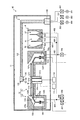
次に、基板処理装置42の配管構成について図11を参照して説明する。図11は、第1の実施形態に係る基板処理装置42の構成を示す模式図である。
<1-5. Configuration of substrate processing section>
Next, the piping configuration of the
図11に示すように、基板保持部12が備える回転保持機構121には、中空円筒状の回転軸121aの上端部に円環状のテーブル121bが水平に取付けられている。テーブル121bの周縁部には、基板Wの周縁部と接触して基板Wを水平に保持する複数個の基板保持体121cが円周方向に間隔をあけて取付けられている。
As shown in FIG. 11, an annular table 121b is horizontally attached to the upper end of a hollow cylindrical
回転軸121aには、回転駆動機構111が接続されており、回転駆動機構111によって回転軸121a及びテーブル121bを回転させ、テーブル121bに基板保持体121cで保持した基板Wを回転させる。この回転駆動機構111は、制御部101(図1参照)に接続しており、制御部101によって回転制御される。
A
また、基板保持部12には、回転軸121a及びテーブル121bの中央の中空部に昇降軸121dが昇降自在に挿通され、昇降軸121dの上端部に円板状の昇降板121eが取付けられている。昇降板121eの周縁部には、基板Wの下面と接触して基板Wを昇降させる複数個の昇降ピン121fが円周方向に間隔をあけて取付けられている。
Further, in the
昇降軸121dには、昇降機構112が接続されており、昇降機構112によって昇降軸121d及び昇降板121eが昇降し、昇降ピン121fに保持された基板Wが昇降する。かかる昇降機構112は、制御部101に接続されており、かかる制御部101によって昇降制御される。
A
また、基板保持部12が備える処理液回収機構122は、基板Wの下方及び外周外方を囲むとともに基板Wの上方を開放させた回収カップ122aを備える。回収カップ122aは、基板Wの外周外方に回収口122bを形成するとともに、下方に回収口122bに連通する回収空間122cを形成する。
The processing
また、回収カップ122aは、回収空間122cの底部に同心リング状の仕切壁122dを形成して、回収空間122cの底部を同心二重リング状の第1回収部122eと第2回収部122fとに区画する。第1回収部122eおよび第2回収部122fの底部には、排出口122g,122hが円周方向に間隔をあけて形成される。
Further, the
排出口122gは、排液管401を介してバルブ206に接続される。排出口122gから排出される薬液(ここでは、IPA)は、排液管401およびバルブ206を介して基板処理装置42の外部へ排出される。
The
排液管401には、ノズル洗浄装置14が備えるダミーディスペンス槽53の排出口532に接続される排液管402が接続される。これにより、ダミーディスペンス処理において第3ノズル136からダミーディスペンス槽53に吐出されるIPAは、排液管402およびバルブ206を介して基板処理装置42の外部へ排出される。
A
このように、基板処理装置42では、基板処理時に基板保持部12の排出口122gから排出されるIPAの排出経路と、ダミーディスペンス処理時にダミーディスペンス槽53の排出口532から排出されるIPAの排出経路とが共通化されている。
As described above, the
排出口122hは、排液管403を介してバルブ207,208,209にそれぞれ接続される。バルブ207,208,209は、制御部101によって開閉制御される。たとえば酸系の薬液を排出する場合には、制御部101によってバルブ207が開放される。これにより、排出口122hから排出された酸系の薬液が、排液管403およびバルブ207を介して基板処理装置42の外部へ排出される。
The
また、アルカリ系の薬液を排出する場合には、制御部101によってバルブ208が開放され、排出口122hから排出されたアルカリ系の薬液が、排液管403およびバルブ208を介して基板処理装置42の外部へ排出される。また、薬液を回収する場合には、制御部101によってバルブ209が開放され、排出口122hから排出された薬液が、排液管403およびバルブ209を介して回収される。
Further, when discharging the alkaline chemical solution, the
排液管403には、ノズル洗浄装置14が備える洗浄槽51の排出口512に接続された排液管404が接続される。また、排液管404には、オーバーフロー槽52の排出口522に接続される排液管405が接続される。
A
これにより、ノズル洗浄処理において洗浄槽51およびオーバーフロー槽52から排出される洗浄液と、ダミーディスペンス処理において第1ノズル134および第2ノズル135からそれぞれ吐出される純水およびDHFとは、バルブ207〜209のいずれかを介して基板処理装置42の外部へ排出される。
Thereby, the cleaning liquid discharged from the
このように、基板処理装置42では、基板処理時に基板保持部12の排出口122hから排出される薬液の排出経路と、ノズル洗浄処理時およびダミーディスペンス処理時に洗浄槽51およびオーバーフロー槽52から排出される薬液の排出経路とが共通化されている。
Thus, in the
回収カップ122aには、仕切壁122dの中途部において排出口122g,122hよりも上方に複数の排気口122iが円周方向に間隔をあけて形成される。
In the
また、回収カップ122aは、昇降カップ122lを有する。昇降カップ122lは、仕切壁122dの直上方に所定の間隔をあけて配置される。昇降カップ122lには、昇降カップ122lを昇降させる昇降機構(図示せず)が接続される。かかる昇降機構は、制御部101によって昇降制御される。
Further, the
昇降カップ122lは、上端部に回収カップ122aの回収口122bまで内側上方に向けて傾斜する傾斜壁部122pを有する。傾斜壁部122pは、回収カップ122aの回収口122bまで回収空間122cの傾斜壁に沿って平行に伸延されており、傾斜壁部122pが回収カップ122aの回収空間122cの傾斜壁と近接するようになっている。
The elevating cup 122l has an
そして、図示しない昇降機構を用いて昇降カップ122lを降下させると、回収空間122cの内部において回収カップ122aの傾斜壁と昇降カップ122lの傾斜壁部122pとの間に回収口122bから第1回収部122eの排出口122gへと通じる流路が形成される。
Then, when the elevating cup 122l is lowered using an elevating mechanism (not shown), the first recovery part is formed from the
また、図示しない昇降機構を用いて昇降カップ122lを上昇させると、回収空間122cの内部において昇降カップ122lの傾斜壁部122pの内側に回収口122bから排出口122hへと通じる流路が形成される。
Further, when the elevating cup 122l is raised using an elevating mechanism (not shown), a flow path leading from the
基板処理装置42は、基板処理を行う際、使用する処理液の種類に応じて処理液回収機構122の昇降カップ122lを昇降させて排出口122g,122hのいずれかから排液する。
When performing substrate processing, the
たとえば、第2ノズル135から酸性の処理液であるDHFを基板Wに吐出して基板Wを処理する場合、制御部101は、回転駆動機構111を制御して基板保持部12のテーブル121bを所定回転速度で回転させた状態で、バルブ202を開放する。これにより、DHF供給源302から供給されるDHFが第2ノズル135から基板Wの上面に吐出される。
For example, when processing the substrate W by discharging DHF, which is an acidic processing liquid, from the
このとき、制御部101は、図示しない昇降機構を制御して昇降カップ122lを降下させて、回収口122bから第1回収部122eの排出口122gへと通じる流路を形成しておく。
At this time, the
これにより、基板Wに供給されたDHFは、基板Wの回転による遠心力の作用で基板Wの外周外方へ向けて振り切られ、回収カップ122aの回収口122bから回収空間122cの第1回収部122eに回収される。
As a result, the DHF supplied to the substrate W is shaken off toward the outer periphery of the substrate W by the action of centrifugal force caused by the rotation of the substrate W, and the first recovery portion of the
また、第3ノズル136から有機系の処理液であるIPAを基板Wに吐出して基板Wを処理する場合、制御部101は、回転駆動機構111を制御して基板保持部12のテーブル121bを所定回転速度で回転させた状態で、バルブ203を開放する。これにより、IPA供給源303から供給されるIPAが第3ノズル136から基板Wの上面に吐出される。
In addition, when processing the substrate W by discharging IPA, which is an organic processing liquid, from the
このとき、制御部101は、図示しない昇降機構を制御して昇降カップ122lを上昇させて、回収口122bから第2回収部122fの排出口122hへと通じる流路を形成する。
At this time, the
これにより、基板Wに供給されたIPAは、基板Wの回転による遠心力の作用で基板Wの外周外方へ向けて振り切られ、回収カップ122aの回収口122bから回収空間122cの第2回収部122fに回収される。
As a result, the IPA supplied to the substrate W is spun off toward the outer periphery of the substrate W by the action of the centrifugal force generated by the rotation of the substrate W, and the second recovery portion of the
上述してきたように、第1の実施形態に係るノズル洗浄装置14は、洗浄槽51と、オーバーフロー槽52と、制御部101とを備える。洗浄槽51は、基板Wに処理液を吐出するノズル134〜136の洗浄液を貯留する貯留部511と、所定の水位を超えた洗浄液を貯留部511から排出するオーバーフロー部513とを備える。オーバーフロー槽52は、洗浄槽51に隣接して配置され、オーバーフロー部513から排出される洗浄液を受けて外部へ排出する。制御部101は、ノズル134〜136を移動させる移動機構133を制御する。また、制御部101は、ノズル134〜136を洗浄する場合には、ノズル134〜136を洗浄槽51の貯留部511内へ移動させて貯留部511に貯留された洗浄液に浸漬させ、待機中にノズル134,135から処理液を吐出させるダミーディスペンス処理を行う場合には、ノズル134,135をオーバーフロー槽52へ移動させて処理液をオーバーフロー槽52内に吐出させる。したがって、第1の実施形態に係るノズル洗浄装置14によれば、洗浄性能を向上させさらに小型化を図ることができる。
As described above, the
上述した例では、オーバーフロー槽52にのみ洗浄液をオーバーフローさせることとしたが、洗浄液は、ダミーディスペンス槽53にもオーバーフローさせてもよい。かかる点について図12を参照して説明する。図12は、第1の実施形態の第1の変形例に係るノズル洗浄装置の構成を示す模式図である。
In the example described above, the cleaning liquid is allowed to overflow only into the
図12に示すように、第1の変形例に係るノズル洗浄装置14Aは、上述した洗浄槽51に代えて洗浄槽51Aを備える。洗浄槽51Aは、ダミーディスペンス槽53側の上端部にもオーバーフロー部514を備えており、所定の水位を超えた洗浄液は、オーバーフロー部514からダミーディスペンス槽53へも排出される。
As shown in FIG. 12, the
このように、ダミーディスペンス槽53にも洗浄液をオーバーフローさせることにより、言い換えれば、ダミーディスペンス槽53をオーバーフロー槽としても使用することにより、オーバーフローした洗浄液を利用してダミーディスペンス槽53を洗浄することができる。
In this way, by allowing the cleaning liquid to overflow into the
オーバーフロー部は、オーバーフロー槽52およびダミーディスペンス槽53が洗浄液によって効率的に洗浄されるように構成されてもよい。かかる点について図13を参照して説明する。図13は、第1の実施形態の第2の変形例に係るノズル洗浄装置の構成を示す模式図である。
The overflow part may be configured such that the
図13に示すように、第2の変形例に係るノズル洗浄装置14Bは、洗浄槽51に代えて洗浄槽51Bを備える。洗浄槽51Bは、第1の変形例に係る洗浄槽51Aと同様、オーバーフロー槽52側およびダミーディスペンス槽53側にそれぞれオーバーフロー部513B,514Bを備える。
As illustrated in FIG. 13, the
これらオーバーフロー部513B,514Bは、オーバーフローした洗浄液を鉛直方向(Z軸方向)に対して斜めに流入させる流路を形成する。これにより、オーバーフロー部513B,514Bを介してそれぞれオーバーフロー槽52およびダミーディスペンス槽53に流入した洗浄液は、排出口522,532からすぐには排出されず、オーバーフロー槽52およびダミーディスペンス槽53内で旋回しながら排出される。
These
このように構成することで、オーバーフローした洗浄液がオーバーフロー槽52およびダミーディスペンス槽53内に留まり易くなるため、オーバーフローした洗浄液によるオーバーフロー槽52およびダミーディスペンス槽53を効率的に洗浄することができる。
With this configuration, the overflowing cleaning liquid easily stays in the
(第2の実施形態)
上述した第1の実施形態では、洗浄槽51の両側にそれぞれオーバーフロー槽52およびダミーディスペンス槽53が配置される場合の例について説明した。しかし、ダミーディスペンス槽の配置は、第1の実施形態において示した例に限定されない。以下では、ダミーディスペンス槽の他の配置例について説明する。
(Second Embodiment)
In the first embodiment described above, an example in which the
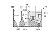
図14は、第2の実施形態に係るノズル洗浄装置の構成を示す模式図である。なお、以下の説明では、既に説明した部分と同様の部分については、既に説明した部分と同一の符号を付し、重複する説明を省略する。 FIG. 14 is a schematic diagram illustrating a configuration of a nozzle cleaning device according to the second embodiment. In the following description, parts that are the same as those already described are given the same reference numerals as those already described, and redundant descriptions are omitted.
図14に示すように、第2の実施形態に係るノズル洗浄装置14Cは、洗浄槽51Cと、オーバーフロー槽52Cと、ダミーディスペンス槽53Cとを備える。
As shown in FIG. 14, the
第2の実施形態に係るノズル洗浄装置14Cにおいて、ダミーディスペンス槽53Cは、オーバーフロー槽52Cに隣接して配置される。具体的には、洗浄槽51C、オーバーフロー槽52Cおよびダミーディスペンス槽53Cは、X軸正方向に、ダミーディスペンス槽53C、オーバーフロー槽52Cおよび洗浄槽51Cの順で並べて配置される。
In the
洗浄槽51Cは、貯留部511Cと、排出口512Cと、オーバーフロー部513Cとを備える。貯留部511Cは、第1の実施形態に係る貯留部511とは異なり、第1ノズル134、第2ノズル135および第3ノズル136を同時に収容可能な大きさに形成される。排出口512Cは、貯留部511Cの下端部に設けられ、オーバーフロー部513Cは、オーバーフロー槽52C側の上端部に形成される。
The
オーバーフロー槽52Cは、第1の実施形態に係るオーバーフロー槽52と同様の貯留部521Cおよび排出口522Cを備えており、オーバーフロー部513Cから流入する洗浄液を貯留部521Cで受けて排出口522Cから排出する。
The
ダミーディスペンス槽53Cは、貯留部531Cと排出口532Cとを備える。貯留部531Cは、第1の実施形態に係る貯留部531とは異なり、第1ノズル134および第2ノズル135を同時に収容可能な大きさに形成される。また、排出口532Cは、貯留部531Cの下端部に設けられる。
The
次に、第2の実施形態に係るノズル洗浄装置14Cの具体的動作について図15A〜図15Eを参照して説明する。図15A〜図15Eは、第2の実施形態に係るノズル洗浄処理およびダミーディスペンス処理の動作例を示す模式図である。
Next, a specific operation of the
まず、制御部101(図1参照)は、移動機構133(図2参照)を制御してノズルヘッド131を移動させて、図15Aに示すように、第1ノズル134、第2ノズル135および第3ノズル136を洗浄槽51Cの貯留部511C内に配置させる。
First, the control unit 101 (see FIG. 1) controls the moving mechanism 133 (see FIG. 2) to move the
つづいて、制御部101は、バルブ204(図6参照)を開放することによって、洗浄液供給部55から洗浄槽51Cの貯留部511C内に洗浄液を供給する。これにより、貯留部511C内に洗浄液が貯留され、貯留部511C内に配置された第1ノズル134、第2ノズル135および第3ノズル136が、かかる洗浄液に浸漬される(図15B参照)。
Subsequently, the
このように、ノズル洗浄装置14Cは、第1ノズル134、第2ノズル135および第3ノズル136を同時に浸漬洗浄する。このとき、貯留部511C内の所定の水位を超えた洗浄液は、オーバーフロー部513Cからオーバーフロー槽52Cへ排出される。
As described above, the
バルブ204を開放してから所定時間経過した後、制御部101は、バルブ204を閉じる。これにより、貯留部511C内の洗浄液が排出口512Cから全て排出される。
After a predetermined time has elapsed since the
つづいて、制御部101は、バルブ205(図6参照)を開放することによって、気体供給部54から気体を噴出させる。そして、制御部101は、移動機構133を制御してノズルヘッド131を上昇および降下させる(図15C参照)。これにより、第1ノズル134、第2ノズル135および第3ノズル136が乾燥する。
Subsequently, the
その後、制御部101は、バルブ205を閉じて気体供給部54からの気体の供給を停止して、ノズル洗浄処理を終える。
Thereafter, the
つづいて、ダミーディスペンス処理を行う場合、制御部101は、移動機構133を制御してノズルヘッド131を移動させて、第1ノズル134および第2ノズル135をダミーディスペンス槽53C内に、第3ノズル136をオーバーフロー槽52C内にそれぞれ配置させる(図15D参照)。
Subsequently, when performing the dummy dispensing process, the
そして、制御部101は、バルブ201〜203を所定時間開放して、第1ノズル134、第2ノズル135および第3ノズル136から処理液を所定時間吐出させる。第1ノズル134および第2ノズル135から吐出される処理液は、ダミーディスペンス槽53Cによって受け止められてダミーディスペンス槽53Cの排出口532Cから基板処理装置42の外部へ排出される。また、第3ノズル136から吐出される処理液は、オーバーフロー槽52Cによって受け止められてオーバーフロー槽52Cの排出口522Cから基板処理装置42の外部に排出される(図15E参照)。
Then, the
なお、第1の実施形態では、1つのノズル(第3ノズル136)からダミーディスペンス槽53内に処理液が吐出されるのに対し、第2の実施形態では、2つのノズル(第1ノズル134および第2ノズル135)のそれぞれからダミーディスペンス槽53C内に処理液が吐出される。このため、図15Eに示すように、第2の実施形態に係るダミーディスペンス槽53Cの排出口532Cは、第1の実施形態に係るダミーディスペンス槽53の排出口532よりも口径が大きく形成される。これにより、ダミーディスペンス処理時の液残り等を防止することができる。
In the first embodiment, the processing liquid is discharged from one nozzle (third nozzle 136) into the
このように、第2の実施形態に係るノズル洗浄装置14Cによれば、ダミーディスペンス槽53Cとオーバーフロー槽52Cとを隣接して設けることにより、第1ノズル134および第2ノズル135(第2の実施形態における「第1のノズル」の一例に相当)のダミーディスペンス処理と、第3ノズル136(第2の実施形態における「第2のノズル」の一例に相当)のダミーディスペンス処理とを同時に実行することができる。したがって、ダミーディスペンス処理に要する時間を短縮することができる。
As described above, according to the
また、第2の実施形態に係るノズル洗浄装置14Cは、第1ノズル134、第2ノズル135および第3ノズル136を同時に収容可能な貯留部511Cを有する洗浄槽51Cを備えるため、ノズル洗浄処理に要する時間を短縮することができる。
Further, the
なお、第2の実施形態に係る洗浄槽51Cの構成は、第1の実施形態に係るノズル洗浄装置14,14A,14Bに対して適用されてもよい。
Note that the configuration of the
(第3の実施形態)
上述してきた各実施形態では、ノズル洗浄装置が、オーバーフロー槽とは別にダミーディスペンス槽を備える場合の例について説明したが、たとえば処理液同士の混蝕が問題とならない場合、ノズル洗浄装置は、必ずしもダミーディスペンス槽を備えることを要しない。そこで、以下では、ダミーディスペンス槽を備えないノズル洗浄装置について説明する。
(Third embodiment)
In each of the embodiments described above, an example in which the nozzle cleaning device includes a dummy dispensing tank in addition to the overflow tank has been described. However, for example, when mixing of processing liquids does not become a problem, the nozzle cleaning apparatus is not necessarily It is not necessary to provide a dummy dispensing tank. Therefore, in the following, a nozzle cleaning apparatus that does not include a dummy dispensing tank will be described.
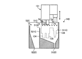
図16は、第3の実施形態に係るノズル洗浄装置の構成を示す模式図である。なお、以下の説明では、既に説明した部分と同様の部分については、既に説明した部分と同一の符号を付し、重複する説明を省略する。 FIG. 16 is a schematic diagram illustrating a configuration of a nozzle cleaning device according to the third embodiment. In the following description, parts that are the same as those already described are given the same reference numerals as those already described, and redundant descriptions are omitted.
図16に示すように、第3の実施形態に係るノズル洗浄装置14Dは、第2の実施形態に係るノズル洗浄装置14Cからダミーディスペンス槽53Cを取り除いた構成を有する。具体的には、ノズル洗浄装置14Dは、洗浄槽51Cと、オーバーフロー槽52Cとを備える。
As shown in FIG. 16, the
次に、第3の実施形態に係るノズル洗浄装置14Dの具体的動作について図17A〜図17Eを参照して説明する。図17A〜図17Eは、第3の実施形態に係るノズル洗浄処理およびダミーディスペンス処理の動作例を示す模式図である。なお、図17A〜図17Cに示すノズル洗浄処理の動作は、図15A〜図15Cに示す動作と同じであるため、ここでの説明を省略する。
Next, a specific operation of the
ダミーディスペンス処理を行う場合、制御部101は、移動機構133を制御してノズルヘッド131を移動させて、第1ノズル134および第2ノズル135をオーバーフロー槽52C内に、第3ノズル136を洗浄槽51C内にそれぞれ配置させる(図17D参照)。
When performing the dummy dispensing process, the
そして、制御部101は、バルブ201〜203を所定時間開放して、第1ノズル134、第2ノズル135および第3ノズル136から処理液を所定時間吐出させる。第1ノズル134および第2ノズル135から吐出される処理液は、オーバーフロー槽52Cによって受け止められてオーバーフロー槽52Cの排出口522Cから基板処理装置42の外部へ排出される。また、第3ノズル136から吐出される処理液は、洗浄槽51Cによって受け止められて洗浄槽51Cの排出口512Cから基板処理装置42の外部に排出される(図17E参照)。
Then, the
このように、第3の実施形態に係るノズル洗浄装置14Dは、洗浄槽51Cを第3ノズル136用のダミーディスペンス槽としても利用することとしたため、装置のさらなる小型化を図ることができる。
As described above, since the
(第4の実施形態)
ノズル洗浄装置は、ノズル洗浄処理を行う前に、洗浄槽51自体を洗浄する槽洗浄処理を行ってもよい。かかる点について図18A〜図18Cを参照して説明する。図18A〜図18Cは、槽洗浄処理の動作例を示す模式図である。なお、ここでは、第1の実施形態に係るノズル洗浄装置14を例に挙げて槽洗浄処理を説明するが、槽洗浄処理は、他のノズル洗浄装置14A〜14Dにおいても実施可能である。
(Fourth embodiment)
The nozzle cleaning device may perform a tank cleaning process for cleaning the
図18Aに示すように、槽洗浄処理は、ノズル洗浄処理においてノズルヘッド131が洗浄槽51内に配置される前(すなわち、図9Aに示す状態よりも前)に行われる。この状態において、制御部101は、まず、バルブ205(図6参照)を開放することによって気体供給部54から気体を噴出させる。これにより、気体供給部54内にゴミ等が存在している場合には、かかるゴミ等を気体供給部54から排出することができる。なお、バルブ205の開放時間は、たとえば30秒である。制御部101は、バルブ205を開放してから所定時間経過した後、バルブ205を閉じる。
As shown in FIG. 18A, the tank cleaning process is performed before the
つづいて、制御部101は、バルブ204(図6参照)を開放することによって、洗浄液供給部55から洗浄槽51の貯留部511内に洗浄液を供給する。これにより、貯留部511内に洗浄液が貯留される。また、貯留部511内の所定の水位を超えた洗浄液は、オーバーフロー部513からオーバーフロー槽52へオーバーフローして、オーバーフロー槽52の排出口522から基板処理装置42の外部へ排出される(図18B参照)。なお、バルブ204の開放時間は、たとえば30秒である。
Subsequently, the
そして、制御部101は、バルブ204を開放してから所定時間経過した後、バルブ204を閉じる。これにより、貯留部511内の洗浄液が排出口512から全て排出されて、槽洗浄処理が終了する(図18C参照)。その後、制御部101は、図9A〜図9Gに示すノズル洗浄処理を開始する。
Then, the
このように、槽洗浄処理を行うことにより、たとえば、前回のノズル洗浄処理においてノズルヘッド131から除去された汚れが、洗浄槽51や洗浄液供給部55(図6参照)の内部に残留していたとしても、かかる汚れをノズル洗浄処理前に除去することができる。したがって、その後に行われるノズル洗浄処理において、このような汚れがノズルヘッド131に再付着することを防止することができる。
As described above, by performing the tank cleaning process, for example, the dirt removed from the
なお、上述した例では、気体供給部54から気体を噴出させた後で、洗浄槽51に洗浄液を貯留してオーバーフローさせることとしたが、気体供給部54から気体を噴出させる処理は、洗浄槽51に洗浄液を貯留してオーバーフローさせる処理の後または前後に行ってもよい。
In the above-described example, after the gas is ejected from the
さらなる効果や変形例は、当業者によって容易に導き出すことができる。このため、本発明のより広範な態様は、以上のように表しかつ記述した特定の詳細および代表的な実施形態に限定されるものではない。したがって、添付の特許請求の範囲およびその均等物によって定義される総括的な発明の概念の精神または範囲から逸脱することなく、様々な変更が可能である。 Further effects and modifications can be easily derived by those skilled in the art. Thus, the broader aspects of the present invention are not limited to the specific details and representative embodiments shown and described above. Accordingly, various modifications can be made without departing from the spirit or scope of the general inventive concept as defined by the appended claims and their equivalents.
W 基板
1 基板処理システム
4 基板処理部
12 基板保持部
13 ノズルユニット
14 ノズル洗浄装置
42 基板処理装置
51 洗浄槽
52 オーバーフロー槽
53 ダミーディスペンス槽
54 気体供給部
55 洗浄液供給部
100 制御装置
101 制御部
131 ノズルヘッド
133 移動機構
134 第1ノズル
135 第2ノズル
136 第3ノズル
511 貯留部
511a 第1内周部
511b 第2内周部
512 排出口
513,514 オーバーフロー部
W Substrate 1
Claims (11)
前記第1のノズルおよび前記第2のノズルを移動させる移動機構と、
前記第1のノズルおよび前記第2のノズルを洗浄するノズル洗浄装置と
を備え、
前記ノズル洗浄装置は、
前記第1のノズルおよび前記第2のノズルを洗浄するための洗浄液を貯留する貯留部と、所定の水位を超えた前記洗浄液を前記貯留部から排出するオーバーフロー部とを備える洗浄槽と、
前記洗浄槽に隣接して配置され、前記オーバーフロー部から排出される洗浄液を受けて外部へ排出するオーバーフロー槽と、
前記第1のノズルから吐出される前記第1の処理液を受けて外部へ排出するダミーディスペンス槽と
を備え、
前記オーバーフロー槽は、
前記第1のノズルが前記貯留部内に配置された場合に前記第2のノズルが配置される位置に設けられ、
前記第1のノズルおよび前記第2のノズルを洗浄する場合には、前記第1のノズルおよび前記第2のノズルを前記洗浄槽の貯留部内で洗浄液に浸漬させ、
前記第1のノズルから前記第1の処理液を吐出させるダミーディスペンス処理を行う場合には、前記ダミーディスペンス槽内へ前記第1のノズルから前記第1の処理液を吐出させ、前記第2のノズルから前記第2の処理液を吐出させるダミーディスペンス処理を行う場合には、前記オーバーフロー槽内へ前記第2のノズルから前記第2の処理液を吐出させること
を特徴とする基板処理装置。 A first nozzle that discharges the first processing liquid to the substrate and a second nozzle that discharges the second processing liquid to the substrate ;
A moving mechanism for moving the first nozzle and the second nozzle;
A nozzle cleaning device for cleaning the first nozzle and the second nozzle,
The nozzle cleaning device includes:
A cleaning tank comprising: a storage part storing a cleaning liquid for cleaning the first nozzle and the second nozzle; and an overflow part discharging the cleaning liquid exceeding a predetermined water level from the storage part;
An overflow tank that is arranged adjacent to the cleaning tank and receives the cleaning liquid discharged from the overflow part and discharges it outside ,
A dummy dispensing tank for receiving the first processing liquid discharged from the first nozzle and discharging it to the outside;
With
The overflow tank is
Provided when the first nozzle is disposed in the reservoir, the second nozzle is disposed;
When cleaning the first nozzle and the second nozzle , the first nozzle and the second nozzle are immersed in a cleaning liquid in the storage section of the cleaning tank,
When performing a dummy dispensing process in which the first processing liquid is discharged from the first nozzle, the first processing liquid is discharged from the first nozzle into the dummy dispensing tank, and the second processing liquid is discharged . when performing dummy dispensing processing for ejecting the second treatment liquid from the nozzle, a substrate processing apparatus, characterized in that from the second nozzle to the overflow tank Ru by ejecting the second processing liquid.
前記第2のノズルが前記貯留部内に配置された場合に前記第1のノズルが配置される位置に設けられること
を特徴とする請求項1に記載の基板処理装置。 The dummy dispensing tank is
The substrate processing apparatus according to claim 1 , wherein the second nozzle is provided at a position where the first nozzle is disposed when the second nozzle is disposed in the storage section.
所定の水位を超えた前記洗浄液を前記貯留部から前記ダミーディスペンス槽へ排出するダミーディスペンス槽側オーバーフロー部
をさらに備えることを特徴とする請求項2に記載の基板処理装置。 The washing tank is
The substrate processing apparatus according to claim 2, further comprising: a dummy dispense tank side overflow section that discharges the cleaning liquid that exceeds a predetermined water level from the storage section to the dummy dispense tank.
前記オーバーフロー槽に隣接して配置され、Arranged adjacent to the overflow tank,
前記第1のノズルから前記第1の処理液を吐出させるダミーディスペンス処理と、前記第2のノズルから前記第2の処理液を吐出させるダミーディスペンス処理とが同時に行われることA dummy dispensing process for discharging the first processing liquid from the first nozzle and a dummy dispensing process for discharging the second processing liquid from the second nozzle are performed simultaneously.
を特徴とする請求項1に記載の基板処理装置。The substrate processing apparatus according to claim 1.
前記第1のノズルおよび前記第2のノズルを同時に収容可能な大きさに形成されること
を特徴とする請求項1〜4のいずれか一つに記載の基板処理装置。 The storage part of the washing tank is
The substrate processing apparatus according to claim 1, wherein the substrate processing apparatus is formed to have a size capable of simultaneously accommodating the first nozzle and the second nozzle.
をさらに備え、
前記貯留部は、
上端部から下端部にかけて内寸が一定な第1内周部と、
前記第1内周部の下端部に上端部が連接し、上端部から下端部に向かうに従って漸次縮径する第2内周部と
を備え、
前記洗浄液供給部は、
平面視において前記第1内周部の中心からずれた位置へ向けて前記洗浄液を吐出することによって、前記貯留部内を旋回する旋回流を形成すること
を特徴とする請求項1〜5のいずれか一つに記載の基板処理装置。 A cleaning liquid supply section for supplying the cleaning liquid into the storage section;
The reservoir is
A first inner periphery having a constant inner dimension from the upper end to the lower end;
An upper end connected to the lower end of the first inner periphery, and a second inner periphery that gradually decreases in diameter from the upper end toward the lower end.
The cleaning liquid supply unit
The swirl flow swirling in the storage section is formed by discharging the cleaning liquid toward a position deviated from the center of the first inner peripheral section in a plan view. The substrate processing apparatus as described in one.
前記第2内周部の下端部に、前記貯留部に貯留された洗浄液を排出する排出口
をさらに備え、
前記排出口は、
平面視において前記第1内周部の中心からずれた位置に配置されること
を特徴とする請求項6に記載の基板処理装置。 The washing tank is
A discharge port for discharging the cleaning liquid stored in the storage portion at the lower end of the second inner peripheral portion;
The outlet is
The substrate processing apparatus according to claim 6, wherein the substrate processing apparatus is disposed at a position shifted from a center of the first inner peripheral portion in plan view.
を特徴とする請求項1〜7のいずれか一つに記載の基板処理装置。 Before cleaning the second nozzle, the cleaning liquid is supplied into the storage section of the cleaning tank, and the cleaning liquid exceeding a predetermined water level is discharged from the storage section to the overflow section to clean the inside of the storage section. The substrate processing apparatus according to claim 1, wherein:
前記第1のノズルから吐出される前記第1の処理液を受けて外部へ排出するダミーディスペンス槽へ前記第1のノズルを移動させて、前記ダミーディスペンス槽内へ前記第1のノズルから前記第1の処理液を吐出させる第1のダミーディスペンス工程と、
前記第1のノズルが前記貯留部内に配置された場合に前記第2のノズルが配置される位置に、前記洗浄槽に隣接して配置され、前記オーバーフロー部から排出される洗浄液を受けて外部へ排出するオーバーフロー槽へ前記第2のノズルを移動させて、前記オーバーフロー槽内へ前記第2のノズルから前記第2の処理液を吐出させる第2のダミーディスペンス工程と
を含むことを特徴とするノズル洗浄方法。 A first nozzle and reservoir for storing a cleaning liquid for cleaning the second Nozzle for discharging a second treatment liquid to the substrate for discharging the first processing liquid to a substrate, said exceeding a predetermined water level washings by moving the said to the storage portion the first nozzle and the second nozzle of the cleaning tank and a overflow portion for discharging from the reservoir, the first nozzle to the cleaning liquid stored in the reservoir And an immersion step of immersing the second nozzle,
The first nozzle is moved to a dummy dispensing tank that receives and discharges the first processing liquid discharged from the first nozzle to the outside, and the first nozzle enters the dummy dispensing tank. A first dummy dispensing step of discharging one processing liquid;
When the first nozzle is disposed in the reservoir, the second nozzle is disposed adjacent to the cleaning tank and receives the cleaning liquid discharged from the overflow portion to the outside. by moving the second nozzle to the overflow vessel for discharging, characterized in that it comprises a second dummy dispense step of discharging the second processing liquid from the second nozzle to the overflow vessel nozzle Cleaning method.
前記第2のダミーディスペンス工程時に前記ダミーディスペンス槽内へ前記第1のノズルから前記第1の処理液を吐出させること
を特徴とする請求項9に記載のノズル洗浄方法。 The first dummy dispensing process includes:
The nozzle cleaning method according to claim 9, wherein the first processing liquid is discharged from the first nozzle into the dummy dispensing tank during the second dummy dispensing step.
を含むことを特徴とする請求項9または10に記載のノズル洗浄方法。 Before the immersion step, and supplies the cleaning liquid to the reservoir portion of the cleaning tank, the tank cleaning process for cleaning the reservoir portion by discharging the cleaning liquid exceeds a predetermined water level from the reservoir to the overflow portion nozzle cleaning method according to claim 9 or 10, characterized in that it comprises.
Priority Applications (4)
| Application Number | Priority Date | Filing Date | Title |
|---|---|---|---|
| JP2013247813A JP6077437B2 (en) | 2013-05-31 | 2013-11-29 | Substrate processing apparatus and nozzle cleaning method |
| TW103118472A TWI569348B (en) | 2013-05-31 | 2014-05-27 | Substrate processing device and nozzle cleaning method |
| US14/291,494 US9764345B2 (en) | 2013-05-31 | 2014-05-30 | Substrate processing apparatus and nozzle cleaning method |
| KR1020140065736A KR102237507B1 (en) | 2013-05-31 | 2014-05-30 | Substrate processing apparatus and nozzle cleaning method |
Applications Claiming Priority (3)
| Application Number | Priority Date | Filing Date | Title |
|---|---|---|---|
| JP2013115904 | 2013-05-31 | ||
| JP2013115904 | 2013-05-31 | ||
| JP2013247813A JP6077437B2 (en) | 2013-05-31 | 2013-11-29 | Substrate processing apparatus and nozzle cleaning method |
Publications (3)
| Publication Number | Publication Date |
|---|---|
| JP2015006652A JP2015006652A (en) | 2015-01-15 |
| JP2015006652A5 JP2015006652A5 (en) | 2016-01-21 |
| JP6077437B2 true JP6077437B2 (en) | 2017-02-08 |
Family
ID=51983736
Family Applications (1)
| Application Number | Title | Priority Date | Filing Date |
|---|---|---|---|
| JP2013247813A Active JP6077437B2 (en) | 2013-05-31 | 2013-11-29 | Substrate processing apparatus and nozzle cleaning method |
Country Status (4)
| Country | Link |
|---|---|
| US (1) | US9764345B2 (en) |
| JP (1) | JP6077437B2 (en) |
| KR (1) | KR102237507B1 (en) |
| TW (1) | TWI569348B (en) |
Cited By (1)
| Publication number | Priority date | Publication date | Assignee | Title |
|---|---|---|---|---|
| WO1999067802A1 (en) * | 1998-06-25 | 1999-12-29 | Hamamatsu Photonics K.K. | Photocathode |
Families Citing this family (9)
| Publication number | Priority date | Publication date | Assignee | Title |
|---|---|---|---|---|
| JP6461617B2 (en) * | 2015-01-20 | 2019-01-30 | 株式会社Screenホールディングス | Substrate processing equipment |
| JP6527716B2 (en) * | 2015-02-27 | 2019-06-05 | 株式会社Screenホールディングス | Substrate processing apparatus and control method of substrate processing apparatus |
| JP6534578B2 (en) * | 2015-08-03 | 2019-06-26 | 株式会社Screenホールディングス | Substrate processing equipment |
| JP6407829B2 (en) * | 2015-09-30 | 2018-10-17 | 東京エレクトロン株式会社 | Substrate liquid processing apparatus and substrate liquid processing method |
| KR101710859B1 (en) * | 2016-06-16 | 2017-03-02 | 주식회사 위드텍 | Apparatus and method for measuring the ionic contaminant of the wafer surface |
| CN106449481A (en) * | 2016-10-24 | 2017-02-22 | 上海华力微电子有限公司 | Method for improving nozzle technology of single-chip cleaning machine, and nozzle cleaning device |
| JP6914050B2 (en) * | 2017-02-15 | 2021-08-04 | 東京エレクトロン株式会社 | Board processing equipment |
| KR102186069B1 (en) * | 2018-05-11 | 2020-12-07 | 세메스 주식회사 | Apparatus and Method for treating substrate |
| KR102483378B1 (en) * | 2021-03-31 | 2022-12-30 | 엘에스이 주식회사 | Pocket type nozzle cleaning apparatus |
Family Cites Families (24)
| Publication number | Priority date | Publication date | Assignee | Title |
|---|---|---|---|---|
| DE69731934T2 (en) * | 1996-12-19 | 2005-11-17 | Texas Instruments Inc., Dallas | Apparatus and method for delivering spin on glass over a substrate |
| JP3381776B2 (en) * | 1998-05-19 | 2003-03-04 | 東京エレクトロン株式会社 | Processing device and processing method |
| JP3511106B2 (en) * | 1999-04-07 | 2004-03-29 | 東京応化工業株式会社 | Cleaning device for slit nozzle |
| JP3824054B2 (en) * | 2000-03-24 | 2006-09-20 | 東京エレクトロン株式会社 | Coating processing method and coating processing apparatus |
| KR100396829B1 (en) * | 2000-11-10 | 2003-09-02 | (주)케이.씨.텍 | Device for cleaning a brush of a brush type of substrate cleaning apparatus |
| WO2004047161A1 (en) * | 2002-11-18 | 2004-06-03 | Tokyo Electron Limited | Insulation film formation device |
| JP4030860B2 (en) * | 2002-11-18 | 2008-01-09 | 東京エレクトロン株式会社 | Insulating film forming equipment |
| KR100987674B1 (en) * | 2003-11-27 | 2010-10-13 | 엘지디스플레이 주식회사 | Apparatus And Method For Cleaning Nozzle |
| JP4202934B2 (en) * | 2004-01-23 | 2008-12-24 | 東京エレクトロン株式会社 | Coating device |
| JP2005262172A (en) * | 2004-03-22 | 2005-09-29 | Toyota Motor Corp | Washing method and washing device |
| JP4526288B2 (en) * | 2004-03-25 | 2010-08-18 | 東京応化工業株式会社 | Adjusting device and adjusting method for slit nozzle tip |
| KR100700181B1 (en) * | 2004-12-31 | 2007-03-27 | 엘지.필립스 엘시디 주식회사 | Slit coater having standby unit of nozzle and method of coating using thereof |
| JP4606234B2 (en) * | 2005-04-15 | 2011-01-05 | 東京エレクトロン株式会社 | Liquid processing method and liquid processing apparatus |
| JP2007258462A (en) | 2006-03-23 | 2007-10-04 | Dainippon Screen Mfg Co Ltd | Apparatus and method for processing substrate |
| JP4582654B2 (en) * | 2006-05-23 | 2010-11-17 | 東京エレクトロン株式会社 | NOZZLE CLEANING DEVICE, NOZZLE CLEANING METHOD, NOZZLE CLEANING PROGRAM, AND COMPUTER-READABLE RECORDING MEDIUM CONTAINING THE PROGRAM |
| KR100876377B1 (en) * | 2006-06-16 | 2008-12-29 | 세메스 주식회사 | Nozzle cleaning mechanism and substrate processing apparatus including the same |
| KR100895030B1 (en) * | 2007-06-14 | 2009-04-24 | 세메스 주식회사 | Apparatus for treating substrate and method for cleaning nozzle thereof |
| KR20080112541A (en) * | 2007-06-21 | 2008-12-26 | 삼성전자주식회사 | Print-head cleaning device and ink-jet type image forming apparatus having the same |
| KR100941075B1 (en) * | 2007-12-27 | 2010-02-09 | 세메스 주식회사 | Unit for providing chemical liquid, apparatus and method for treating substrate using the same |
| JP5036664B2 (en) * | 2008-09-04 | 2012-09-26 | 東京エレクトロン株式会社 | Nozzle cleaning in liquid treatment, treatment liquid drying prevention method and apparatus |
| TWM354844U (en) * | 2008-09-19 | 2009-04-11 | Advanced Wireless Semiconductor Company | Equipment for cleaning photoresist nozzle |
| JP2010225832A (en) * | 2009-03-24 | 2010-10-07 | Dainippon Screen Mfg Co Ltd | Substrate processing apparatus and substrate processing method |
| KR20110008539A (en) * | 2009-07-20 | 2011-01-27 | 세메스 주식회사 | Apparatus for cleaning nozzle and apparatus for coating chemical including the same |
| TWI566311B (en) * | 2011-06-27 | 2017-01-11 | 聯華電子股份有限公司 | Semiconductor apparatus and operation method thereof |
-
2013
- 2013-11-29 JP JP2013247813A patent/JP6077437B2/en active Active
-
2014
- 2014-05-27 TW TW103118472A patent/TWI569348B/en active
- 2014-05-30 US US14/291,494 patent/US9764345B2/en active Active
- 2014-05-30 KR KR1020140065736A patent/KR102237507B1/en active IP Right Grant
Cited By (1)
| Publication number | Priority date | Publication date | Assignee | Title |
|---|---|---|---|---|
| WO1999067802A1 (en) * | 1998-06-25 | 1999-12-29 | Hamamatsu Photonics K.K. | Photocathode |
Also Published As
| Publication number | Publication date |
|---|---|
| JP2015006652A (en) | 2015-01-15 |
| TWI569348B (en) | 2017-02-01 |
| US20140352730A1 (en) | 2014-12-04 |
| TW201519348A (en) | 2015-05-16 |
| KR20140141514A (en) | 2014-12-10 |
| US9764345B2 (en) | 2017-09-19 |
| KR102237507B1 (en) | 2021-04-06 |
Similar Documents
| Publication | Publication Date | Title |
|---|---|---|
| JP6077437B2 (en) | Substrate processing apparatus and nozzle cleaning method | |
| JP5965729B2 (en) | Nozzle cleaning apparatus, nozzle cleaning method, and substrate processing apparatus | |
| TWI709169B (en) | Substrate processing method and substrate processing apparatus | |
| JP5694118B2 (en) | Liquid processing apparatus and liquid processing method | |
| US10639683B2 (en) | Recovery piping cleaning method and substrate processing apparatus | |
| US11031261B2 (en) | Liquid processing apparatus | |
| KR102605399B1 (en) | Substrate processing method and substrate processing apparatus | |
| US20170200624A1 (en) | Substrate processing apparatus and method of cleaning substrate processing apparatus | |
| US10290518B2 (en) | Substrate liquid processing apparatus | |
| JP6211458B2 (en) | Substrate liquid processing apparatus and substrate liquid processing method | |
| JP6301281B2 (en) | Substrate liquid processing method, substrate liquid processing apparatus, and storage medium | |
| KR20190112639A (en) | Substrate processing method and substrate processing apparatus | |
| JP6739285B2 (en) | Substrate processing equipment | |
| KR20210042380A (en) | Substrate processing apparatus and substrate processing method | |
| JP5676362B2 (en) | Liquid processing apparatus and cleaning method for liquid processing apparatus | |
| JP6387329B2 (en) | Substrate processing apparatus and nozzle cleaning method | |
| JP5293790B2 (en) | Liquid processing apparatus, liquid processing method, and storage medium | |
| JP2014143310A (en) | Substrate processing apparatus, substrate processing method, and storage medium | |
| JP2018129476A (en) | Substrate processing device | |
| JP2016092368A (en) | Cleaning method of substrate liquid processing device, storage medium, and substrate liquid processing device | |
| JP2016106401A (en) | Liquid processing apparatus |
Legal Events
| Date | Code | Title | Description |
|---|---|---|---|
| A521 | Request for written amendment filed |
Free format text: JAPANESE INTERMEDIATE CODE: A523 Effective date: 20151126 |
|
| A621 | Written request for application examination |
Free format text: JAPANESE INTERMEDIATE CODE: A621 Effective date: 20151126 |
|
| A977 | Report on retrieval |
Free format text: JAPANESE INTERMEDIATE CODE: A971007 Effective date: 20161012 |
|
| A131 | Notification of reasons for refusal |
Free format text: JAPANESE INTERMEDIATE CODE: A131 Effective date: 20161025 |
|
| A521 | Request for written amendment filed |
Free format text: JAPANESE INTERMEDIATE CODE: A523 Effective date: 20161130 |
|
| TRDD | Decision of grant or rejection written | ||
| A01 | Written decision to grant a patent or to grant a registration (utility model) |
Free format text: JAPANESE INTERMEDIATE CODE: A01 Effective date: 20161220 |
|
| A61 | First payment of annual fees (during grant procedure) |
Free format text: JAPANESE INTERMEDIATE CODE: A61 Effective date: 20170112 |
|
| R150 | Certificate of patent or registration of utility model |
Ref document number: 6077437 Country of ref document: JP Free format text: JAPANESE INTERMEDIATE CODE: R150 |
|
| R250 | Receipt of annual fees |
Free format text: JAPANESE INTERMEDIATE CODE: R250 |
|
| R250 | Receipt of annual fees |
Free format text: JAPANESE INTERMEDIATE CODE: R250 |
|
| R250 | Receipt of annual fees |
Free format text: JAPANESE INTERMEDIATE CODE: R250 |
|
| R250 | Receipt of annual fees |
Free format text: JAPANESE INTERMEDIATE CODE: R250 |
|
| R250 | Receipt of annual fees |
Free format text: JAPANESE INTERMEDIATE CODE: R250 |