JP5293790B2 - Liquid processing apparatus, liquid processing method, and storage medium - Google Patents
Liquid processing apparatus, liquid processing method, and storage medium Download PDFInfo
- Publication number
- JP5293790B2 JP5293790B2 JP2011207933A JP2011207933A JP5293790B2 JP 5293790 B2 JP5293790 B2 JP 5293790B2 JP 2011207933 A JP2011207933 A JP 2011207933A JP 2011207933 A JP2011207933 A JP 2011207933A JP 5293790 B2 JP5293790 B2 JP 5293790B2
- Authority
- JP
- Japan
- Prior art keywords
- liquid
- processing
- nozzle
- unit
- wafer
- Prior art date
- Legal status (The legal status is an assumption and is not a legal conclusion. Google has not performed a legal analysis and makes no representation as to the accuracy of the status listed.)
- Active
Links
- 239000007788 liquid Substances 0.000 title claims abstract description 320
- 238000012545 processing Methods 0.000 title claims abstract description 217
- 238000003672 processing method Methods 0.000 title claims description 11
- 238000003860 storage Methods 0.000 title claims description 8
- 239000000758 substrate Substances 0.000 claims abstract description 47
- 238000000034 method Methods 0.000 claims abstract description 17
- 238000004140 cleaning Methods 0.000 claims description 29
- 238000004590 computer program Methods 0.000 claims description 3
- 239000013013 elastic material Substances 0.000 claims description 3
- 239000011148 porous material Substances 0.000 claims description 3
- 235000012431 wafers Nutrition 0.000 description 147
- 238000011161 development Methods 0.000 description 68
- 238000012546 transfer Methods 0.000 description 41
- XLYOFNOQVPJJNP-UHFFFAOYSA-N water Substances O XLYOFNOQVPJJNP-UHFFFAOYSA-N 0.000 description 36
- 239000002131 composite material Substances 0.000 description 27
- 239000007789 gas Substances 0.000 description 26
- 239000011248 coating agent Substances 0.000 description 13
- 238000000576 coating method Methods 0.000 description 13
- 230000002093 peripheral effect Effects 0.000 description 12
- 238000001816 cooling Methods 0.000 description 10
- 238000010438 heat treatment Methods 0.000 description 9
- 230000000694 effects Effects 0.000 description 8
- 239000002245 particle Substances 0.000 description 8
- 238000012360 testing method Methods 0.000 description 7
- 238000007599 discharging Methods 0.000 description 5
- 230000001681 protective effect Effects 0.000 description 5
- 238000010586 diagram Methods 0.000 description 4
- 238000011156 evaluation Methods 0.000 description 4
- 239000003973 paint Substances 0.000 description 3
- 238000005406 washing Methods 0.000 description 3
- 101100221835 Arabidopsis thaliana CPL2 gene Proteins 0.000 description 2
- IJGRMHOSHXDMSA-UHFFFAOYSA-N Atomic nitrogen Chemical compound N#N IJGRMHOSHXDMSA-UHFFFAOYSA-N 0.000 description 2
- 238000013459 approach Methods 0.000 description 2
- 239000000919 ceramic Substances 0.000 description 2
- 238000001035 drying Methods 0.000 description 2
- 230000001965 increasing effect Effects 0.000 description 2
- 239000000463 material Substances 0.000 description 2
- 239000003595 mist Substances 0.000 description 2
- 238000012805 post-processing Methods 0.000 description 2
- 238000007781 pre-processing Methods 0.000 description 2
- 239000004065 semiconductor Substances 0.000 description 2
- 239000000126 substance Substances 0.000 description 2
- 101100221836 Arabidopsis thaliana CPL3 gene Proteins 0.000 description 1
- 101100221837 Arabidopsis thaliana CPL4 gene Proteins 0.000 description 1
- 101100065702 Arabidopsis thaliana ETC3 gene Proteins 0.000 description 1
- 101100536545 Arabidopsis thaliana TCL2 gene Proteins 0.000 description 1
- 101150075071 TRS1 gene Proteins 0.000 description 1
- 238000009825 accumulation Methods 0.000 description 1
- 230000015572 biosynthetic process Effects 0.000 description 1
- 238000011109 contamination Methods 0.000 description 1
- 230000007547 defect Effects 0.000 description 1
- 230000003028 elevating effect Effects 0.000 description 1
- 230000002708 enhancing effect Effects 0.000 description 1
- 238000002474 experimental method Methods 0.000 description 1
- 239000012530 fluid Substances 0.000 description 1
- 230000005484 gravity Effects 0.000 description 1
- 238000011086 high cleaning Methods 0.000 description 1
- 238000004519 manufacturing process Methods 0.000 description 1
- 229910052757 nitrogen Inorganic materials 0.000 description 1
- 230000003287 optical effect Effects 0.000 description 1
- 238000005192 partition Methods 0.000 description 1
- 229920002120 photoresistant polymer Polymers 0.000 description 1
- 239000002904 solvent Substances 0.000 description 1
- 238000004528 spin coating Methods 0.000 description 1
- 239000007921 spray Substances 0.000 description 1
- 238000004381 surface treatment Methods 0.000 description 1
- 230000002195 synergetic effect Effects 0.000 description 1
- 239000002699 waste material Substances 0.000 description 1
- 238000009736 wetting Methods 0.000 description 1
Images


Landscapes
- Coating Apparatus (AREA)
- Exposure Of Semiconductors, Excluding Electron Or Ion Beam Exposure (AREA)
- Cleaning Or Drying Semiconductors (AREA)
- Photosensitive Polymer And Photoresist Processing (AREA)
- Application Of Or Painting With Fluid Materials (AREA)
Abstract
Description
本発明は、基板に処理液を供給して液処理を行う液処理装置、液処理方法及び記憶媒体に関する。 The present invention relates to a liquid processing apparatus, a liquid processing method, and a storage medium that perform a liquid processing by supplying a processing liquid to a substrate.
半導体製造工程の一つであるフォトレジスト工程においては、半導体ウエハ(以下、ウエハという)の表面にレジストを塗布し、このレジストを所定のパターンで露光した後に現像してレジストパターンを形成している。このような処理は、一般にレジストの塗布、現像を行う塗布、現像装置に露光装置を接続したシステムを用いて行われる。 In the photoresist process, which is one of the semiconductor manufacturing processes, a resist is applied to the surface of a semiconductor wafer (hereinafter referred to as a wafer), the resist is exposed in a predetermined pattern, and then developed to form a resist pattern. . Such a process is generally performed by using a system in which an exposure apparatus is connected to a coating and developing apparatus for coating and developing a resist.
この塗布、現像装置にはウエハに処理液を供給して液処理を行う液処理モジュールが設けられている。この液処理モジュールとしては例えば現像液を供給して現像を行う現像モジュール(現像装置)がある。現像モジュールは、ウエハを保持する基板保持部と、排液手段及び排気手段を備え、その基板保持部に保持されたウエハを囲むように設けられたカップ体とを含む現像処理部を備えている。また、その他に現像モジュールは前記ウエハに現像液を供給するための現像液ノズルと、その現像液ノズルを待機させるための待機部と、現像液供給後に洗浄液を供給する洗浄液ノズルと、を備えている。 The coating and developing apparatus is provided with a liquid processing module for supplying a processing liquid to the wafer and performing liquid processing. As this liquid processing module, for example, there is a developing module (developing apparatus) for supplying a developing solution and performing development. The development module includes a development processing unit including a substrate holding unit that holds a wafer, and a cup body that includes a draining unit and an exhausting unit and is provided so as to surround the wafer held by the substrate holding unit. . In addition, the developing module includes a developing solution nozzle for supplying the developing solution to the wafer, a standby unit for making the developing solution nozzle stand by, and a cleaning solution nozzle for supplying the cleaning solution after supplying the developing solution. Yes.
スループットの向上を図るために、この現像モジュールにおいて前記現像処理部を横方向に複数配設し、その現像処理部の配列方向の延長線上に前記待機部を設け、そして各カップに共通の現像液ノズルが各現像処理部の上方領域と待機部との間を移動して現像液を供給する構成とする場合がある。この場合、一の現像処理部のウエハに現像液の供給が行われている間に他の現像処理部ではウエハに洗浄液が供給されたり、基板保持部を回転させてスピン乾燥が行われたりする。 In order to improve the throughput, a plurality of the development processing units are arranged in the horizontal direction in the development module, the standby unit is provided on an extension line in the arrangement direction of the development processing units, and a common developer for each cup There is a case where the nozzle moves between the upper region of each development processing unit and the standby unit to supply the developer. In this case, while the developer is supplied to the wafer of one development processing unit, the cleaning solution is supplied to the wafer in the other development processing unit, or the substrate holding unit is rotated to perform spin drying. .
ところでウエハに現像液供給を行った後、現像液ノズルの下端に現像液の液滴が付着し、垂れ下がる場合がある。そして現像装置を上記のように構成した場合、現像液ノズルが現像処理部間を移動する間にこの液滴が乾燥を終えたウエハ上に落下して、パーティクルとなり現像欠陥となってしまうおそれがある。また、その液滴が長時間ノズルに垂れ下がっていると、液滴が雰囲気中のパーティクルを吸収し、そしてそのような液滴が現像液ノズルから吐出される現像液に混じってウエハに供給されてしまう、いわゆるノズル汚染へと繋がる場合がある。現在ではレジストパターンの微細化が進み、僅かなパーティクルのウエハへの付着が歩留りの低下を招くおそれがあることから、このように現像液ノズルから垂れ下がる液滴を除去する要求が高くなっている。 By the way, after supplying the developer to the wafer, the developer droplets may adhere to the lower end of the developer nozzle and hang down. When the developing device is configured as described above, while the developer nozzle moves between the development processing units, the droplets may fall on the dried wafer and become particles and develop defects. is there. Also, if the droplets hang down on the nozzle for a long time, the droplets absorb particles in the atmosphere, and such droplets are mixed with the developer discharged from the developer nozzle and supplied to the wafer. May lead to so-called nozzle contamination. At present, the resist pattern has been miniaturized, and a slight amount of particles adhering to the wafer may lead to a decrease in yield. Therefore, there is an increasing demand for removing droplets dripping from the developer nozzle.
この液滴の除去を行うためには、現像液ノズルに吸引機構を設けて現像液ノズルの吐出口から吸引を行い、液滴を吸い込むことや、ウエハ以外の場所に向けて現像液を吐出し、液滴を押し流すいわゆるダミーディスペンスと呼ばれる処理を行うことが考えられる。しかし前記吸引機構を設けることはコスト高になるし、ダミーディスペンスを行うことは処理タクトの延長によるスループットの低下や現像処理のコストの上昇を招くおそれがある。 In order to remove these droplets, a suction mechanism is provided in the developer nozzle and suction is performed from the discharge port of the developer nozzle to suck the droplets or to discharge the developer toward a place other than the wafer. It is conceivable to perform a process called so-called dummy dispensing that pushes the droplets. However, providing the suction mechanism increases the cost, and performing dummy dispensing may cause a decrease in throughput due to an extension of processing tact and an increase in development processing cost.
また、ウエハへの現像液の供給方法としては、回転するウエハに現像液ノズルから現像液を吐出させながら、その現像液ノズルをウエハの直径方向に移動させてその表面に液膜を形成する場合がある。この場合、ウエハWに吐出された現像液がウエハW上で撥ねてパーティクルとなることを抑えるために、現像液ノズル11は図18に示すようにその吐出口12が斜めに傾いた状態で移動手段に取り付けられ、その移動手段によって傾いた状態のまま、ウエハW上及び現像処理部間を移動させることが検討されている。
As a method for supplying the developer to the wafer, the developer nozzle is moved in the diameter direction of the wafer while discharging the developer from the developer nozzle to the rotating wafer to form a liquid film on the surface. There is. In this case, in order to prevent the developer discharged on the wafer W from being repelled on the wafer W and becoming particles, the
しかし、このように現像液ノズル11を傾けた場合には図中の鎖線間で示す吐出口12の投影領域14から下方にずれた位置に液滴13が形成されるため、上記のように吸引機構を設けたり、ダミーディスペンスを行ったりしても十分に液滴13が除去できないおそれがある。
However, when the
現像装置について説明してきたが、現像液の代わりにレジストなどの各種処理液を塗布する液処理装置についても、使用する処理液が現像液と異なる他は、既述の現像装置と同様の装置構成とされる場合がある。そして、その液処理装置についてもこのように処理液を供給するノズルから液滴が垂れ下がり、垂れ下がる間にその液滴に含まれる溶剤が揮発し、液滴中の成分の濃度が変化することが考えられる。そして、そのように成分の濃度が変化した液滴が液処理前、液処理後のウエハ上に落下すればその液滴がパーティクルとなってウエハを汚染したり、ウエハの面内における処理の均一性が低下したりすることで、やはり歩留りが低下するおそれがある。 The developing apparatus has been described. The liquid processing apparatus for applying various processing liquids such as a resist instead of the developing liquid also has the same apparatus configuration as the above-described developing apparatus except that the processing liquid to be used is different from the developing liquid. It may be said. In the liquid processing apparatus, the liquid droplets hang down from the nozzle that supplies the processing liquid in this way, and the solvent contained in the liquid droplets volatilizes while the liquid drips, and the concentration of the components in the liquid droplets changes. It is done. If a droplet with such a changed component concentration falls on the wafer before and after the liquid treatment, the droplet becomes a particle and contaminates the wafer, or the processing on the wafer surface is uniform. As a result, the yield may also decrease.
特許文献1には一つのカップ体の側方位置に液滴除去用の針を設けることが記載されている。しかし上記のように複数のカップ体を設けて処理を行うことについては記載されておらず、上記の問題を解決するには不十分である。
本発明はこのような事情の下になされたものであり、その目的は、横方向に一列に配置された基板保持部を備えた複数の液処理部と、これら液処理部に対して共用化された処理液ノズルと、を備えた液処理装置において、前記処理液ノズルからの基板への処理液の落下を抑え、歩留りの低下を防ぐことができる液処理装置、液処理方法及び記憶媒体を提供することにある。 The present invention has been made under such circumstances, and an object thereof is to share a plurality of liquid processing units having substrate holding units arranged in a row in the horizontal direction with respect to these liquid processing units. A liquid processing apparatus, a liquid processing method, and a storage medium capable of preventing the processing liquid from dropping from the processing liquid nozzle onto the substrate and preventing a decrease in yield. It is to provide.
本発明の液処理装置は、上側に開口部が形成されたカップ体の中に基板を水平に保持する基板保持部を設けて構成され、各々横方向に一列に配置された複数の液処理部と、
これら複数の液処理部に対して共用化され、基板に処理液を供給するための処理液ノズルと、
前記液処理部の列の延長線上に設けられ、処理液ノズルを待機させるための待機部と、
前記液処理部の各々の上方領域と前記待機部との間で前記液処理ノズルを液処理部の列に従って移動させるための移動手段と、
前記カップ体の開口部間において処理液ノズルの移動路の下方側に設けられ、前記移動手段により移動する処理液ノズルから垂れた液滴に接触して、その液滴を処理液ノズルから除去するための液取り部と、
カップ体の開口部間における前記移動路に位置すると共に一の液処理部から他の液処理部に向けて横方向に移動する途中の当該処理液ノズルに洗浄液を供給して洗浄し、その洗浄液が前記液取り部にて処理液ノズルから除去されるように前記液取り部に設けられた洗浄液供給部と、
を備えたことを特徴とする。
The liquid processing apparatus of the present invention is configured by providing a substrate holding portion for horizontally holding a substrate in a cup body having an opening formed on the upper side, and each of the plurality of liquid processing portions arranged in a row in the horizontal direction. When,
A common processing liquid nozzle for supplying a processing liquid to the substrate;
A standby unit provided on an extended line of the row of the liquid processing units, for waiting the processing liquid nozzle;
Moving means for moving the liquid processing nozzle according to a row of liquid processing units between an upper region of each of the liquid processing units and the standby unit;
Provided below the processing liquid nozzle moving path between the opening portions of the cup body, contacts the liquid droplet dripping from the processing liquid nozzle moved by the moving means, and removes the liquid droplet from the processing liquid nozzle. A liquid collecting part for
The cleaning liquid is supplied to the processing liquid nozzle, which is located on the moving path between the opening portions of the cup body and moves in the lateral direction from one liquid processing section to the other liquid processing section, and is cleaned. Cleaning liquid supply unit provided in the liquid removal unit so that is removed from the treatment liquid nozzle in the liquid removal unit,
It is provided with.
前記処理液ノズルは例えば斜め下方に前記処理液を吐出する吐出口を備えており、また前記液取り部は例えば弾性材により構成され、そして前記液取り部は例えば更に前記待機部に設けられている。そして、前記待機部に位置する処理液ノズルに洗浄液を供給するための洗浄液供給部を備えていてもよい。前記液取り部は毛細管現象により液滴をその内部に吸収して除去するために、その表面に多数の凹部を有していてもよい。前記凹部は例えば上方に向けて開口すると共に、上方から下方に向かうにつれて末広がりに構成される。前記液取り部は例えば毛細管現象により液滴をその内部に吸収して除去するために、多孔質材料により構成されている。前記処理液は例えば現像液であり、前記基板はその表面にレジストが塗布され、露光されたものである。
The processing liquid nozzle includes, for example, a discharge port that discharges the processing liquid obliquely downward, the liquid removing unit is formed of, for example, an elastic material, and the liquid collecting unit is further provided, for example, in the standby unit. Yes. And you may provide the washing | cleaning liquid supply part for supplying a washing | cleaning liquid to the process liquid nozzle located in the said waiting | standby part . The liquid collecting part may have a large number of recesses on the surface in order to absorb and remove the liquid droplets by capillary action. For example, the concave portion opens upward, and is configured to expand toward the bottom from the top. The liquid collecting part is made of a porous material in order to absorb and remove the liquid droplets by capillary action, for example. The processing solution is, for example, a developing solution, and the substrate has a resist coated on the surface and exposed .
本発明の液処理方法は、上側に開口部が形成されたカップ体の中に基板を水平に保持する基板保持部を設けて構成され、各々横方向に一列に配置された複数の液処理部に対して共用化された処理液ノズルから前記基板に処理液を供給する液処理方法において、
前記液処理部の列の延長線上に設けられた、処理液ノズルを待機させるための待機部から、前記複数の液処理部を構成する一の液処理部の上方領域へ、当該一の液処理部の基板に処理液を供給するために前記液処理ノズルを液処理部の列に従って移動手段により移動させる工程と、
次いで、前記待機部に処理液ノズルを戻さずに当該処理液ノズルを前記複数の液処理部を構成する他の液処理部の基板に処理液を供給するために、当該他の液処理部の上方領域へ向けて前記列に従って移動させる工程と、
次いで、前記処理液ノズルが他の液処理部まで横方向に移動する途中で、前記カップ体の開口部間において、当該処理液ノズルに洗浄液供給部により洗浄液を供給して当該処理液ノズルを洗浄し、前記洗浄液供給部を備えると共に処理液ノズルの移動路の下方側に設けられた液取り部を前記移動手段により移動する処理液ノズルから垂れた洗浄液の液滴に接触させる工程と、
前記液取り部に接触した液滴を当該液取り部により処理液ノズルから除去する工程と、
を備えたことを特徴とする。
In the liquid processing method of the present invention, a plurality of liquid processing units each configured in a row in the lateral direction are configured by providing a substrate holding unit for horizontally holding a substrate in a cup body having an opening formed on the upper side. In a liquid processing method for supplying a processing liquid to the substrate from a processing liquid nozzle shared with respect to the substrate,
Provided on the extension of the column of the liquid processing section, from the standby unit for causing the standby processing liquid nozzle, into the upper region of one liquid processing unit constituting the plurality of liquid processing units, liquid processing of the one A step of moving the liquid processing nozzle by a moving means according to a row of liquid processing units in order to supply a processing liquid to the substrate of the unit;
Next, in order to supply the processing liquid to the substrate of another liquid processing unit that constitutes the plurality of liquid processing units without returning the processing liquid nozzle to the standby unit, the other liquid processing unit Moving according to the row toward the upper region ;
Next, the cleaning liquid is supplied to the processing liquid nozzle by the cleaning liquid supply unit between the openings of the cup body while the processing liquid nozzle moves in the lateral direction to the other liquid processing unit to clean the processing liquid nozzle. And a step of bringing a liquid removal section provided on the lower side of the moving path of the processing liquid nozzle with the cleaning liquid supply section into contact with a droplet of the cleaning liquid dripping from the processing liquid nozzle moved by the moving means;
Removing liquid droplets coming into contact with the liquid removal unit from the treatment liquid nozzle by the liquid removal unit;
It is provided with.
前記基板に処理液を供給する工程は、例えば処理液ノズルの吐出口から前記処理液を斜め下方に供給する工程であり、また前記処理液は例えば現像液であり、前記基板はその表面にレジストが塗布され、露光されたものである。 The step of supplying the processing liquid to the substrate is, for example, a step of supplying the processing liquid obliquely downward from a discharge port of a processing liquid nozzle, and the processing liquid is, for example, a developer, and the substrate is resisted on its surface. Is applied and exposed.
基板に対する液処理を行う液処理装置に用いられるコンピュータプログラムが記憶された記憶媒体であって、
前記コンピュータプログラムは、上記の液処理方法を実施するためのものであることを特徴とする。
A storage medium storing a computer program used in a liquid processing apparatus that performs liquid processing on a substrate,
The computer program is for carrying out the liquid processing method described above.
本発明によれば、横方向に一列に配列された複数のカップ体の開口部間において処理液ノズルの移動路の下方側に、移動手段により移動する処理液ノズルから垂れた前記処理液の液滴に接触して、その液滴を処理液ノズルから除去するための液取り部が設けられている。従って、処理液ノズルが基板に処理を行うために待機部と各液処理部とを移動するにあたって、基板上への処理液ノズルからの前記液滴の落下を防ぐことができる。その結果として、その落下した液滴がパーティクルとなったり、基板の処理の面内均一性を低下させたりすることを防ぐことができるため、歩留りの低下を抑えることができる。 According to the present invention, the liquid of the processing liquid that hangs down from the processing liquid nozzle moved by the moving means on the lower side of the moving path of the processing liquid nozzle between the openings of the plurality of cup bodies arranged in a row in the horizontal direction. A liquid removing unit is provided for contacting the droplet and removing the droplet from the treatment liquid nozzle. Accordingly, when the processing liquid nozzle moves between the standby unit and each liquid processing unit in order to perform processing on the substrate, the droplets from the processing liquid nozzle on the substrate can be prevented. As a result, it is possible to prevent the dropped droplets from becoming particles and to reduce the in-plane uniformity of the processing of the substrate, so that a decrease in yield can be suppressed.
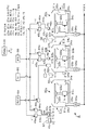
本発明の液処理装置の一例である現像装置2について、その概略構成図である図1を参照しながら説明する。現像装置2は3つの液処理部である現像処理部21a、21b、21cと、複合ノズル部4a〜4cと、現像液ノズル6とを備えている。
A developing
現像処理部21a〜21cは横方向に一列に配列されている。各現像処理部21a〜21cは各々同様に構成されており、ここでは現像処理部21aを例に挙げて説明する。現像処理部21aは夫々ウエハWの裏面中央部を吸着して水平に保持する基板保持部であるスピンチャック22aを備え、スピンチャック22aは回転軸23aを介して回転駆動機構24aと接続されている。スピンチャック22aは、回転駆動機構24aを介してウエハWを保持した状態で鉛直軸回りに回転自在に構成されており、その回転軸上にウエハWの中心が位置するように設定されている。回転駆動機構24aは後述の制御部100からの制御信号を受けてスピンチャック22aの回転速度を制御する。
The
スピンチャック22aの周囲にはスピンチャック22a上のウエハWを囲むようにして上方側に開口部30aを備えたカップ体31aが設けられており、カップ体31aの側周面上端側は内側に傾斜した傾斜部32aを形成している。カップ体31aの底部側には、図1に示すように例えば凹部状をなす液受け部33aが設けられている。液受け部33aは、図示しない隔壁によりウエハWの周縁下方側に全周に亘って外側領域と内側領域とに区画されている。外側領域の底部には貯留した現像液などのドレインを排出するための図示しない廃液口が設けられ、内側領域の底部には処理雰囲気を排気するための排気口34a,34aが設けられている。
Around the
排気口34a,34aには排気管35aの一端が接続されており、排気管35aの他端は、排気ダンパ36aを介して現像処理部21b及び21cの排気管35b、35cと合流し、例えば現像装置2が設置された工場の排気路に接続されている。排気ダンパ36aは、制御部100からの制御信号を受けてカップ体31a内の排気量を制御する。
One end of an
図2、図3は、図1の現像装置2を実際に構成したものを夫々模式的に示した斜視図、上面図である。図中25aは、昇降自在に構成された昇降ピンであり、カップ体31a内に3本設けられている。現像装置2にウエハWを搬送する図示しない基板搬送手段の動作に応じて昇降ピン25aが昇降し、その基板搬送手段とスピンチャック22aとの間でウエハWが受け渡される。
2 and 3 are a perspective view and a top view, respectively, schematically showing the actual configuration of the developing
現像処理部21bの各部について現像処理部21aの各部に対応する部分については、現像処理部21aの説明で用いた数字と同じ数字を用い、且つaの代わりにbを付して各図中に示している。また、現像処理部21cの各部について現像処理部21aの各部に対応する部分については、現像処理部21aの説明で用いた数字と同じ数字を用い、且つaの代わりにcを付して各図中に示している。
For the portions of the
続いて複合ノズル部4a,4b,4cについて説明する。これら複合ノズル部4a,4b,4cは夫々現像処理部21a,21b,21cのウエハWに純水及びN2(窒素)ガスを供給するように構成されており、各複合ノズル部4a〜4cは同様に構成されている。ここでは代表して複合ノズル部4aを例に挙げて説明する。複合ノズル部4aは夫々純水ノズル41a及びN2ガスノズル42aを備えており、これら各ノズル41a,42aはウエハWの直径方向に互いに連接され、各ノズル41a,42aは例えば夫々鉛直下方に開口した円形の細孔である吐出口を夫々備えている。
Next, the
図1に示すように、純水ノズル41aは供給路43を介して純水が貯留された純水供給源5Bに、N2ガスノズル42aは供給路44を介してN2ガスが貯留されたN2ガス供給源5Cに夫々接続されている。純水はウエハWに現像液を供給する前にその現像液の濡れ性を高めるために供給されるプリウエット処理を行うための表面処理液であり、また現像後、不要になった現像液を洗い流すためのリンス液でもある。N2ガスはウエハWを乾燥させるために当該ウエハWに吹き付けられる乾燥用ガスであり、この例ではスピンチャック22a〜22cの回転による液の振り切りの他に、このN2ガスによる供給により洗浄後のウエハWが乾燥される。
As shown in FIG. 1, the
供給路43a,44aには流量制御部45a,46aが夫々介設されている。各流量制御部45a及び46aはバルブやマスフローコントローラなどを含み、制御部100からの制御信号に基づいて各ノズル41a,42aからウエハWへの各純水及びガスの給断を制御する。
図2及び図3に示すように複合ノズル部4aには当該複合ノズル部4aを支持するアーム体47aの一端が接続されており、アーム体47aの他端は移動手段である駆動機構48aに接続されている。駆動機構48aは、現像処理部21a〜21cの配列方向に沿って形成された基台37上を、その配列方向に伸長したガイド49aに沿って移動し、またアーム体47aを介して複合ノズル部4aを昇降させる。この駆動機構48aの移動及び駆動機構48aによる昇降によって、純水ノズル41a、N2ガスノズル42aの吐出口がスピンチャック22aに載置されたウエハWの中心部上に移動し、純水、N2ガスを夫々ウエハWの中心に供給することができる。駆動機構48aの動作は制御部100からの制御信号を受けて制御される。
As shown in FIGS. 2 and 3, one end of an
現像処理部の図示と同様に、複合ノズル部4b,4cにおける複合ノズル部4aと同様に構成された各部については、複合ノズル部の説明に用いた符号と同じ数字の符号を用い、且つ符号中のaをbまたはcに夫々変更して示している。
Similarly to the illustration of the development processing unit, the same numerals as those used for the description of the composite nozzle part are used for the parts configured in the same way as the
各現像処理部21a〜21cの側方には上側が開口したカップ状のノズル待機部51a〜51cが夫々設けられ、その待機部51a〜51cの内部は複合ノズル部4a〜4cの待機領域52a〜52cとして構成されている。そして、複合ノズル部4a〜4cはウエハWに処理を行わないときには、これら待機領域52a〜52cに夫々収納される。
Cup-shaped
続いて、処理液ノズルである現像液ノズル6について図4、図5(a)(b)も参照しながら説明する。現像液ノズル6はその下端面に当該現像液ノズル6の移動方向に沿って扁平なスリット状に開口した吐出口61を備えており、その吐出口61の長さ方向はウエハWの直径及び現像液ノズル6の移動方向に並行している。また、図5(a)に示すように吐出口61は斜めに向けて形成されている。
Next, the developing
図1に示すように現像液ノズル6には現像液供給路62の一端が接続されている。現像液供給路62の他端はバルブやマスフローコントローラなどを含んだ流量制御部63を介して現像液供給源5Aに接続されており、制御部100からの制御信号に従って、流量制御部63が現像液ノズル6からウエハWへの現像液の給断を制御する。
As shown in FIG. 1, one end of a developer supply path 62 is connected to the
図2及び図4に示すように現像液ノズル6はアーム体64の一端に接続されて支持されており、アーム体64の他端は基台37上に設けられた駆動機構65に接続されている。駆動機構65は、基台37に現像処理部21a〜21cの配列方向に伸長するように設けられたガイド60に沿って横方向に移動できるように構成されている。また、駆動機構65はアーム体64を介して現像液ノズル6を昇降させることができる。駆動機構65の動作は制御部100からの制御信号を受けて制御される。
As shown in FIGS. 2 and 4, the
現像液ノズル6は、その駆動機構65により各現像処理部21a〜21cの上方領域と後述の待機部66との間を移動する。また、図6に示すように、現像液ノズル6は各現像処理部21a〜21cに搬入されたウエハWの回転方向に沿って斜めに帯状に現像液を供給しながら、矢印で示すように当該ウエハWの周縁部から中心部に向かって移動して、ウエハWの表面全体に現像液Lの液膜を形成することができる。
The
現像処理部21aのカップ体31aと現像処理部21bのカップ体31bとの間において、待機部52bの上方位置には液取り部7Aが設けられている。また、現像処理部21bのカップ体31bと現像処理部21cのカップ体31cとの間において、待機部52cの上方位置には液取り部7Bが設けられている。これら液取り部7A,7Bは現像液ノズル6の横方向への移動路の下方側に設けられている。
Between the
液取り部7A,7Bは互いに同様に構成されており、図5(a)及び図7(a)を用いて説明する。これらの図に示すように液取り部7A、7Bは、水平に設けられた基部71と、基部71から斜め方向に伸びた板状の液受け部72とを備えており、その液受け部72の先端は現像液ノズル6の横方向への移動方向と並行し、且つそのように横方向に移動する現像液ノズル6の下端と近接するように形成されている。これらの液取り部7A,7Bは、現像液ノズル6から現像液の液滴を効率よく除去するために、例えば高い親水性を有する多孔質のセラミックスにより構成されており、毛細管現象により液滴をその内部に吸収して除去する。
The
図7(a)〜図7(d)は、現像液ノズル6が横方向に移動するときの様子を示しており、現像液ノズル6が移動するときに液取り部7A及び7Bは現像液ノズル6に近接し、現像液ノズル6の下端に垂れ下がって形成された液滴Dに接触し、この液滴Dをその内部に取り込んで除去する。ところで現像液ノズル6の下端に垂れ下がって形成される現像液の液滴Dとしては、繰り返し現像処理を行う過程でその下端への現像液の蓄積によって次第に大きくなり、所定の大きさになったときに重力によって現像液ノズル6から落下するが、この落下前に除去できればよいので、図5(a)中の現像液ノズル6の下端と液取り部7Aとの距離h1はこの液滴Dが落下するときの大きさに応じて任意に設定され、例えば1.5mmである。
FIGS. 7A to 7D show a state in which the
基台37において、現像処理部21a〜21cの配列方向の延長線上には上側が開口したカップ状に形成された待機部66が設けられており、その待機部66の内部は現像液ノズル6の待機領域67として構成されている。現像液ノズル6は、ウエハWに処理を行わないときにはこの待機領域67に収納され、現像処理を行うときに前記駆動機構65を介して当該待機領域67から各現像処理部21a〜21cへ移動する。
In the
待機領域67には液取り部7Cが設けられている。図4に示すように液取り部7Cは、液取り部7A,7Bと同様に構成されており、現像液ノズル6が待機部66に収納されたときに液受け部72の先端は現像液ノズル6の吐出口62に近接し、また吐出口62の長さ方向と、この先端とが並行するように設けられている。図8(a)〜(d)は、現像液ノズル6が待機部6に収納され、現像液ノズル6から垂れた現像液の液滴Dを液取り部7Cが吸収して、除去する様子を示している。図8(d)中に示した待機部6に収納されたときの現像液ノズル6の下端と液取り部7Cとの距離h2はこの液滴Dが落下するときの大きさに応じて任意に設定され、例えば1.5mmである。
The
続いて制御部100について説明する。制御部100は例えばコンピュータからなり、不図示のプログラム格納部を有している。このプログラム格納部には、後述の作用で説明する現像処理が行われるように命令が組まれた例えばソフトウエアからなるプログラムが格納され、このプログラムが制御部100に読み出されることで制御部100はウエハの回転速度、各ノズルの移動、ウエハへの現像液、純水及びN2ガスの供給などを制御する。このプログラムは、例えばハードディスク、コンパクトディスク、マグネットオプティカルディスクまたはメモリーカードなどの記憶媒体に収納された状態でプログラム格納部に格納される。 Next, the control unit 100 will be described. The control unit 100 is formed of a computer, for example, and has a program storage unit (not shown). The program storage unit stores a program made of software, for example, in which instructions are set so that the development processing described in the operation described later is performed, and the control unit 100 reads the program into the control unit 100 to read the control unit 100. It controls the rotation speed of the wafer, the movement of each nozzle, the supply of the developer, pure water and N 2 gas to the wafer. This program is stored in the program storage unit while being stored in a storage medium such as a hard disk, a compact disk, a magnetic optical disk, or a memory card.
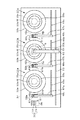
続いて、この現像装置2に順次ウエハWが搬入されたときに、行われる処理の一例について図9〜図12を参照しながら説明する。ウエハWは例えば不図示の基板搬送手段により現像処理部21a,21b,21cの順に搬送され、また各ウエハWの表面にはレジストが塗布されており、そのレジストが所定の露光処理を受けているものとする。また便宜上、現像処理部21a,21b,21cに搬入されるウエハWを夫々便宜上、ウエハW1,W2,W3と記載する。
Next, an example of processing performed when the wafers W are sequentially loaded into the developing
また、既述のように繰り返し現像処理を行う度に現像液ノズル6の下端に現像液が溜まり、当該ノズル6に付着した液滴Dが大きくなる。そして、液滴Dが所定のサイズになったときに液取り部7A〜7Cにより除去できるように現像液ノズル6と各液取り部との距離を調整すればよいが、下記の説明では現像液の液滴Dが除去される様子を明確に示すために説明の便宜上、この液滴DがウエハWに処理を行う度に現像液ノズル6に垂れ下がり、処理を行う度にその液滴Dが除去されるように液取り部7A〜7Cの位置が調整されているものとする。
Further, as described above, the developer is accumulated at the lower end of the
図9(a)に示すように処理開始前において現像液ノズル6、複合ノズル部4a〜4cは、夫々待機部66,51a〜51cに収納されている。各カップ体31a〜31c内の排気量が所定の排気量になり、ウエハW1が現像処理部21aのスピンチャック22aに受け渡され、所定の回転数で回転すると共に複合ノズル部4aがウエハW1上に移動し、純水ノズル41aがウエハW1の中心部に純水Fを吐出する。吐出された純水Fは、遠心力により周縁部へと展伸されるいわゆるスピンコーティングによってウエハW1を覆い、既述のプリウエットが行われる(図9(b))。
As shown in FIG. 9A, the
純水Fの供給が停止し、複合ノズル部4aがウエハW1の周縁部側へと移動すると共に現像液ノズル6が待機部66からウエハW1の周縁部上へと移動する。そして、現像液ノズル6は現像液Lを供給しながらウエハW1の中心部上へと移動し(図9(c))、ウエハW1の表面全体が現像液Lにより覆われる。その後、現像液ノズル6からの現像液Lの吐出が停止し、現像液ノズル6が待機部66に戻る(図9(d))。
The supply of pure water F stops, the
現像液ノズル6が待機部66内の待機領域67に収納され、図8(a)〜(d)で示したように現像液ノズル6の下端が液取り部7Cに近接し、その下端から垂れた液滴Dが液取り部7Cに接触して、当該液取り部7Cに吸収されて除去される。また、複合ノズル部4aがウエハW1の中心部上に移動し、ウエハW1の中心部上に純水Fが供給されてウエハW1表面の現像液Lが洗い流される。その一方で、基板処理部21bのスピンチャック22bにウエハW2が受け渡される(図9(e))。
The
然る後、ウエハW2が所定の回転数で回転し、複合ノズル部4bが待機部51bからウエハW2上に移動し、純水ノズル41bがウエハW2の中心部上に純水Fを吐出して、ウエハW2の表面が純水Fにより覆われると共に、現像液ノズル6がウエハW2の周縁部上へ移動する。その一方で純水ノズル41aからウエハW1への純水Fの供給が停止する(図10(a))。
Thereafter, the wafer W2 is rotated at a predetermined rotational speed, the
N2ガスノズル42aがウエハW1の中心部上に移動し、N2ガスがウエハW1に吐出されて、回転による純水の振り切りとこのガス供給との相乗作用でウエハW1が乾燥される。その一方で、純水ノズル41bからウエハW2への純水Fの吐出が停止し、複合ノズル部4bがウエハW2の周縁部上へ移動し、現像液ノズル6が現像液Lを吐出しながらウエハW2の周縁部上から中心部上へ移動して(図10(b))、ウエハW2の表面全体が現像液Lに被覆される。
The N 2 gas nozzle 42a moves onto the center of the wafer W1, N 2 gas is discharged onto the wafer W1, and the wafer W1 is dried by the synergistic action of the pure water spun off by rotation and the gas supply. On the other hand, the discharge of pure water F from the
その後、前記ウエハW1へのN2ガスの吐出が停止すると共にウエハW1の回転が停止し、複合ノズル部4aが待機部51aに戻る一方で、ウエハW2への現像液Lの供給が停止する。続いて、現像液ノズル6は図中矢印で示すように液取り部7Aの上方を通過し、図7(a)〜(d)で説明したように現像液ノズル6の下端に垂れた液滴Dが液取り部7Aに接触し、吸収されて除去され(図10(c)、(d))、現像液ノズル6はウエハW1の上方を通過して待機部66に戻る(図10(e))。また、複合ノズル部4bがウエハW2の中心部上に移動し、純水FをウエハW2に供給して、ウエハW2表面の現像液Lが洗い流される。その一方で、現像処理部21cのスピンチャック22cにウエハW3が受け渡される(図11(a))。
Thereafter, the discharge of N 2 gas to the wafer W1 is stopped and the rotation of the wafer W1 is stopped, and the
続いてウエハW3が所定の回転数で回転し、複合ノズル部4cが待機部51cからウエハW3上に移動し、純水ノズル42cがウエハW3の中心部上に純水Fを吐出して、スピンコーティングによりウエハW3の表面が純水Fにより覆われると共に現像液ノズル6がウエハW3の周縁部上へ移動する。また、その一方で純水ノズル41bからの純水Fの供給が停止し、N2ガスノズル42bがウエハW2の中心部上に移動する(図11(b))。
Subsequently, the wafer W3 is rotated at a predetermined number of revolutions, the
そして、N2ガスがウエハW2の中心部上に吐出されてウエハW2が乾燥される一方で、純水ノズル41cからの純水Fの吐出が停止し、複合ノズル部4cがウエハW3の周縁部上へ移動する。そして、現像液ノズル6が現像液Lを吐出しながらウエハW3の周縁部上から中心部上へ移動し(図11(c))、ウエハW3の表面全体が現像液Lに被覆される。
Then, N 2 gas is discharged onto the central portion of the wafer W2 to dry the wafer W2, while the discharge of pure water F from the
その後、前記ウエハW2へのN2ガスの吐出が停止すると共にウエハW2の回転が停止して、複合ノズル部4bが待機部51bに戻る一方で、ウエハW3への現像液Lの供給が停止する。そして、現像液ノズル6は図中矢印で示すように液取り部7Bの上方を通過し、図7で説明したように現像液ノズル6の下端に垂れた液滴Dが液取り部7Bに接触して吸収され、除去される(図11(d)、(e))。その後、現像液ノズル6は現像処理部21b,21aの上方を通過して待機部66に戻る(図12(a))。また、複合ノズル部4cがウエハW3の中心部上に移動し、ウエハW3の中心部上に純水Fが供給されてウエハW3表面の現像液Lが洗い流される(図12(b))。
Thereafter, the discharge of N 2 gas to the wafer W2 stops and the rotation of the wafer W2 stops, and the
その後、純水ノズル41cからの純水Fの供給が停止し、N2ガスノズル42cがウエハW3の中心部上に移動して、N2ガスノズル42cからN2ガスがウエハW3の中心部上に吐出されてウエハW3が乾燥される(図12(c))。その後N2ガスの供給が停止すると共にウエハW3の回転が停止し、複合ノズル部4cが待機部51cに戻り(図12(d))、基板搬送手段によりウエハW3が現像処理部31cから搬出される。
Thereafter, the supply stop of the pure water F from the
この現像装置2によれば、横方向に一列に配列された現像処理部21a〜21cのカップ体31a〜31c間において、駆動機構65により移動する現像液ノズル6の移動路の下方側に、その現像液ノズル6の下端に近接し、当該現像液ノズル6から垂れた現像液の液滴Dに接触して、その液滴Dを現像液ノズル6から除去するための液取り部7A,7Bが、その現像液ノズル6の移動軌道上に設けられている。従って現像液ノズル6がウエハWに処理を行うために待機部66と各現像処理部21a〜21cとを移動し、現像液が除去されて乾燥したウエハW上を通過するにあたって、その乾燥したウエハW上への現像液ノズル6からの前記液滴Dの落下を防ぐことができる。従ってその液滴がパーティクルとなってウエハWを汚染することが防がれるので、歩留りの低下を抑えることができる。また、現像液ノズル6の移動中にその液滴Dが除去されるので、液滴Dを除去するための時間を必要としない。その結果としてスループットの低下を抑えることができる。
According to the developing
また、この現像装置2は待機部66においても液取り部7Cを備えており、ノズル6が横方向に移動するときだけでなく待機部66に収納されたときにも液滴Dの除去が行われるので、より確実に既述の現像液ノズル6から乾燥したウエハWへの液滴Dの落下を防ぐことができる。
Further, the developing
上記の例では3枚のウエハWが現像処理される様子を説明しているが、3枚以上のウエハWを処理する場合には、例えば続けて現像処理部21a、21b、21cの順に繰り返しウエハWが搬送されて、上記の例と同様に現像処理が行われる。
In the above example, the state in which three wafers W are developed is described. However, in the case of processing three or more wafers W, for example, the wafers are successively repeated in the order of the
また、上記の例ではウエハWに現像液を供給する毎に現像液ノズル6が待機部66に戻っているがこのように処理の度に待機部66に戻らずに、一の現像処理部で現像液を供給したら直接他の現像処理部に移動して現像液を供給し、何枚かウエハWに現像液を供給した後に待機部66に戻ってもよい。また、現像処理部21a〜21cへのウエハWの搬送順も上記の通りでなくてもよく、例えば現像処理部21a,21bにこの順で繰り返しウエハWが搬送され、所定の枚数これら現像処理部21a及び21bにウエハWが搬送されたら現像処理部21cにウエハWが搬送されるようにし、この搬送順に現像処理が行われるようにしてもよい。これらのように現像処理を行う場合も各現像処理部21a〜21c間を移動するときに液滴が除去されるので上記の実施形態と同様の効果が得られる。
In the above example, every time the developer is supplied to the wafer W, the
液取り部としては例えば図13(a)にその外観を、図13(b)にその側面を夫々示すように構成してもよい。液滴の高い除去効果を得るためにこの液取り部81は櫛形に形成されており、その表面には現像液ノズル6の移動方向に沿って多数の溝(凹部)82が形成されている。そして、既述の実施形態と同様に現像液ノズル6の下端が近接して、液滴Dがその液取り部81の表面に付着すると、図13(b)に矢印で示すように液滴Dが毛細管現象によりその溝82内に進入する。また、溝82内に現像液を多く貯留させることにより、当該液取り部81の交換の頻度が高くなることを防ぐために、この液取り部81において図13(c)に示すように溝82の下方側が広がるように構成されていてもよい。
For example, the liquid collecting portion may be configured such that its external appearance is shown in FIG. 13 (a) and its side surface is shown in FIG. 13 (b). In order to obtain a high droplet removal effect, the
ところで、この例では現像液ノズル6の吐出口61は斜めに開口する代わりに、垂直方向に開口していてもよいが、背景技術の欄で説明したように、斜め方向に開口した現像液ノズル6を用いた場合の方がダミーディスペンスや液の吸引などを行っても、現像液ノズルからの液滴の落下を防ぎにくいので、既述の液取り部を設けることが特に有効になる。
By the way, in this example, the
上記の各液取り部を構成する材料としてはセラミックスに限られないが、高い液滴Dの除去効果を得るために親水性の材料を用いることが好ましい。また、その表面状態を荒くすることにより、高い現像液の除去効果を得ることができるので好ましい。また、各液取り部を弾性材を用いて構成してもよく、この場合は現像液ノズル6が各液取り部と接触しても、これら液取り部及び現像液ノズルの破損を防ぐことができるので、現像液ノズルと液取り部との間隔の調整に手間をかけることを抑えることができる。
The material constituting each of the liquid collecting portions is not limited to ceramics, but a hydrophilic material is preferably used in order to obtain a high droplet D removal effect. Further, it is preferable to roughen the surface state because a high developer removing effect can be obtained. In addition, each liquid collecting part may be configured by using an elastic material. In this case, even if the
また、ウエハWへの液滴Dの落下を防ぐことができればよいので、液取り部7A,7Bはカップ体31a〜31cの開口部31a〜31c間に設けられていればよく、例えばカップ体31a〜31cの上側の傾斜部32a〜32c上に設けられていてもよい。
Further, since it is only necessary to prevent the droplet D from dropping onto the wafer W, the
また、上記の例では現像処理部21a〜21cが直線方向に配列され、その列の延長線上に待機部66が設けられているが、現像処理部21a〜21c及び待機部66が周方向に配列されており、現像液ノズル6がその配列方向に移動し、その現像液ノズル6の移動路の下方側に液取り部7A,7Bが設けられてもよい。現像処理部及び液取り部の数としては既述の実施形態に限られるものではない。
In the above example, the developing
また、液取り部としては図14(a)、(b)に示す構成としてもよい。この液取り部9は基台91上に側面視三角形状の液受け部92を備えている。また、基台91上には斜め方向に純水などの洗浄液を吐出する洗浄液ノズル93が設けられている。図中94は基台91に設けられた排液口であり、不図示の排液路に接続されている。この液取り部9は例えば液受け部7A〜7Cの代わりに各カップ体31a〜31c間及び待機領域67に設けられる。この例では現像処理を行うための現像液ノズル90は斜め方向に円形に開口した吐出口97を備えており、基部96を介して既述のアーム体64に接続され、現像液ノズル6と同様に昇降及び横方向への移動を行うことができる。
Moreover, it is good also as a structure shown to FIG. 14 (a), (b) as a liquid-removal part. The liquid collecting part 9 includes a
例えば、カップ体31a〜31c間において設けられた液受け部92に現像液ノズル90が横方向から移動して近づくと、現像液の液滴Dが液受け部92に接触し、液受け部92を伝わって基台91へと流れ落ちる。さらに洗浄液ノズル93から現像液ノズル90に向けて洗浄液が吐出されて、その洗浄液により液滴Dが洗い流される。そして洗い流された液はノズル90の下端から液受け部92へ伝わり、その基台91へと流れ落ち、その流れ落ちた排液は、排液口94から除去される。この液取り部9は、液取り部7Cの代わりに待機領域67に設けてもよい。また、この例において洗浄液ノズル93を設けず、液受け部92に接触した液滴を当該液受け部92の下方に伝わらせることだけで現像液ノズル6からの液滴の除去を行ってもよい。
For example, when the
洗浄液を吐出するノズル93としては、現像液ノズル90についての高い洗浄効果を得て液滴Dの除去効果を高めるために、例えば洗浄液の液体と気体とを混合して洗浄液の霧を発生させてその霧を噴霧するいわゆる2流体ノズルを用いてもよい。また、そのように除去効果を高める目的のために例えば1MHz程度の超音波をかけた洗浄液を吐出する、いわゆるメガソニックノズルを用いてもよい。なお、現像液ノズル90の代わりに既述の現像液ノズル6に対してこの液取り部9を用いてもよい。
As the
本発明の現像装置への適用例について説明してきたが、例えばレジスト塗布装置などの他の液処理装置へも本発明を適用することができる。この場合、処理液ノズルからの処理液が、当該処理液による処理前及び処理後の基板への落下することを防ぎ、パーティクルが発生したり、基板の処理の面内均一性が低下したりすることを防ぐことができる。その結果として歩留りの低下を防ぐことができる。 Although the application example of the present invention to the developing device has been described, the present invention can also be applied to other liquid processing devices such as a resist coating device. In this case, the treatment liquid from the treatment liquid nozzle is prevented from falling onto the substrate before and after the treatment with the treatment liquid, and particles are generated or the in-plane uniformity of the treatment of the substrate is reduced. Can be prevented. As a result, a decrease in yield can be prevented.
以下、上記の現像装置2が組み込まれた塗布、現像装置101について説明する。図15は塗布、現像装置101に露光装置C4が接続されたレジストパターン形成システムの平面図を示しており、図16は同システムの斜視図である。また、図17は塗布、現像装置101の縦断面図である。この塗布、現像装置101にはキャリアブロックC1が設けられており、その載置台111上に載置された密閉型のキャリア110から受け渡しアーム112がウエハWを取り出して処理ブロックC2に受け渡し、処理ブロックC2から受け渡しアーム112が処理済みのウエハWを受け取ってキャリア110に戻すように構成されている。キャリア110は多数枚のウエハWを含み、各ウエハWは順次処理ブロックC2へと搬送される。
Hereinafter, the coating and developing
前記処理ブロックC2は、図16に示すようにこの例では現像処理を行うための第1のブロック(DEV層)B1、レジスト膜の下層に形成される反射防止膜の形成処理を行うための第2のブロック(BCT層)B2、レジスト膜の塗布を行うための第3のブロック(COT層)B3、レジスト膜の上層側に形成される反射防止膜の形成を行うための第4のブロック(ITC層)B4を、下から順に積層して構成されている。 As shown in FIG. 16, the processing block C2 is a first block (DEV layer) B1 for performing development processing and a first processing for forming an antireflection film formed under the resist film in this example. 2 block (BCT layer) B2, a third block (COT layer) B3 for applying a resist film, a fourth block for forming an antireflection film formed on the upper layer side of the resist film ( ITC layer) B4 is laminated in order from the bottom.
処理ブロックC2の各層は平面視同様に構成されている。第3のブロック(COT層)B3を例に挙げて説明すると、COT層B3は塗布膜としてレジスト膜を形成するためのレジスト膜形成モジュールと、このレジスト膜形成モジュールにて行われる処理の前処理及び後処理を行うための加熱・冷却系の処理モジュール群を構成する棚ユニットU1〜U4と、前記レジスト膜形成モジュールと加熱・冷却系の処理モジュール群との間に設けられ、これらの間でウエハWの受け渡しを行う搬送アームA3と、により構成されている。 Each layer of the processing block C2 is configured similarly to a plan view. The third block (COT layer) B3 will be described as an example. The COT layer B3 is a resist film forming module for forming a resist film as a coating film, and pre-processing of processing performed in the resist film forming module. And the shelf units U1 to U4 constituting the heating / cooling system processing module group for performing post-processing, and the resist film forming module and the heating / cooling system processing module group, And a transfer arm A3 that transfers the wafer W.
前記棚ユニットU1〜U4は搬送アームA3が移動する搬送領域R1に沿って配列され、夫々上記の加熱モジュール、冷却モジュールが積層されることにより構成される。加熱モジュールは載置されたウエハを加熱するための加熱板を備えており、冷却モジュールは載置されたウエハを冷却するための冷却板を備えている。 The shelf units U1 to U4 are arranged along the transfer region R1 in which the transfer arm A3 moves, and are configured by stacking the heating module and the cooling module, respectively. The heating module includes a heating plate for heating the mounted wafer, and the cooling module includes a cooling plate for cooling the mounted wafer.
第2のブロック(BCT層)B2、第4のブロック(ITC層)B4については、前記レジスト膜形成モジュールに相当する反射防止膜形成モジュール、保護膜形成モジュールが夫々設けられ、これらモジュールにおいてレジストの代わりに処理液として反射防止膜形成用の薬液、保護膜形成用の薬液が夫々ウエハWに供給されることを除けばCOT層B3と同様の構成である。 For the second block (BCT layer) B2 and the fourth block (ITC layer) B4, an antireflection film forming module and a protective film forming module corresponding to the resist film forming module are provided, respectively. Instead, the configuration is the same as that of the COT layer B3 except that a chemical solution for forming an antireflection film and a chemical solution for forming a protective film are supplied to the wafer W as processing solutions.
第1のブロック(DEV層)B1については一つのDEV層B1内にレジスト膜形成モジュールに対応する現像モジュール113が2段に積層されており、各現像モジュール113は夫々既述の現像装置2に相当し、共通の筐体内に3基の現像処理部や既述の各ノズルを含んでいる。また、DEV層B1にはこの現像モジュール113の前処理及び後処理を行うための加熱・冷却系の処理モジュール群を構成する棚ユニットU1〜U4が設けられている。そしてDEV層B1内には、これら2段の現像モジュールと、前記加熱・冷却系の処理モジュールとにウエハWを搬送するための搬送アームA1が設けられている。つまり2段の現像モジュールに対して搬送アームA1が共通化されている構成となっている。この搬送アームA1が上記の基板搬送手段に相当する。
For the first block (DEV layer) B1, development modules 113 corresponding to the resist film forming modules are stacked in two stages in one DEV layer B1, and each development module 113 is connected to the
更に処理ブロックC2には、図15及び図17に示すように棚ユニットU5が設けられ、キャリアブロックC1からのウエハWは前記棚ユニットU5の一つの受け渡しユニット、例えば第2のブロック(BCT層)B2の対応する受け渡しユニットCPL2に順次搬送される。第2のブロック(BCT層)B2内の搬送アームA2は、この受け渡しユニットCPL2からウエハWを受け取って各ユニット(反射防止膜形成モジュール及び加熱・冷却系の処理ユニット群)に搬送し、これらユニットにてウエハWには反射防止膜が形成される。 Further, the processing block C2 is provided with a shelf unit U5 as shown in FIGS. 15 and 17, and the wafer W from the carrier block C1 is one transfer unit of the shelf unit U5, for example, a second block (BCT layer). It is sequentially conveyed to the corresponding delivery unit CPL2 of B2. The transfer arm A2 in the second block (BCT layer) B2 receives the wafer W from the transfer unit CPL2 and transfers it to each unit (antireflection film forming module and heating / cooling processing unit group). Thus, an antireflection film is formed on the wafer W.
その後、ウエハWは棚ユニットU5の受け渡しユニットBF2、受け渡しアームD1、棚ユニットU5の受け渡しユニットCPL3に搬送され、そこで例えば23℃に温度調整された後、搬送アームA3を介して第3のブロック(COT層)B3に搬入され、レジスト膜形成モジュールにてレジスト膜が形成される。更にウエハWは、搬送アームA3→棚ユニットU5の受け渡しユニットBF3→受け渡しアームD1を経て棚ユニットU5における受渡しユニットBF3に受け渡される。なおレジスト膜が形成されたウエハWは、第4のブロック(ITC層)B4にて更に保護膜が形成される場合もある。この場合は、ウエハWは受け渡しユニットCPL4を介して搬送アームA4に受け渡され、保護膜の形成された後搬送アームA4により受け渡しユニットTRS4に受け渡される。 Thereafter, the wafer W is transferred to the transfer unit BF2 of the shelf unit U5, the transfer arm D1, and the transfer unit CPL3 of the shelf unit U5, where the temperature is adjusted to, for example, 23 ° C., and then the third block ( COT layer) B3 and a resist film is formed by a resist film forming module. Further, the wafer W is transferred to the transfer unit BF3 in the shelf unit U5 through the transfer arm A3 → the transfer unit BF3 of the shelf unit U5 → the transfer arm D1. The wafer W on which the resist film is formed may further have a protective film formed in the fourth block (ITC layer) B4. In this case, the wafer W is transferred to the transfer arm A4 via the transfer unit CPL4, and after the protective film is formed, the wafer W is transferred to the transfer unit TRS4 by the transfer arm A4.
一方DEV層B1内の上部には、棚ユニットU5に設けられた受け渡しユニットCPL11から棚ユニットU6に設けられた受け渡しユニットCPL12にウエハWを直接搬送するための専用の搬送手段であるシャトルアーム115が設けられている。レジスト膜や更に保護膜の形成されたウエハWは、受け渡しアームD1を介して受け渡しユニットBF3、TRS4から受け取り受け渡しユニットCPL11に受け渡され、ここからシャトルアーム115により棚ユニットU6の受け渡しユニットCPL12に直接搬送され、インターフェイスブロックC3に取り込まれることになる。なお図11中のCPLが付されている受け渡しユニットは温調用の冷却ユニットを兼ねており、BFが付されている受け渡しユニットは複数枚のウエハWを載置可能なバッファユニットを兼ねている。
On the other hand, in the upper part of the DEV layer B1, a
次いで、ウエハWはインターフェイスアーム116により露光装置C4に搬送され、ここで所定の露光処理が行われた後、棚ユニットU6の受け渡しユニットTRS6に載置されて処理ブロックC2に戻される。戻されたウエハWは、第1のブロック(DEV層)B1にて現像処理が行われ、搬送アームA1により棚ユニットU5の受け渡しユニットTRS1に受け渡される。その後、受け渡しアーム112を介してキャリア110に戻される。
Next, the wafer W is transferred to the exposure apparatus C4 by the
(評価試験1)
現像液ノズル6において、その下端からどの程度下方まで垂れ下がった液滴Dが落下するのかを確認した。結果として液滴の大きさが1mm、2mm、3mmの場合においては液滴の落下は起きなかったが、液滴の大きさが4mmになると現像液ノズル6の先端から落下することが確認された。そして、この結果を踏まえて、現像液ノズル6が待機部66に収納されたとき当該現像液ノズル6の下端と液取り部7Cとの距離h2を2mmに設定し、続いて現像液ノズル6を液取り部7Cに対して上昇させ、現像液ノズルの下端から2mm強下側へ垂れ下がった液滴を形成した。そして、現像液ノズル6を下降させ、待機部66に収納した後、現像液ノズル6を上昇させて、液滴の有無を観察した。この現像液ノズル6を上昇させての液滴の形成と現像液ノズル6の待機部6への収納とを50回繰り返し行った。
(Evaluation Test 1)
In the developing
評価試験1の結果、現像液ノズル6が下降する毎に液滴は現像液ノズル6の下端から除去された。この試験から上記の実施形態のように現像装置2に液取り部7Cを設けることで液滴の除去が行うことができることが示された。また、現像液ノズル6が接近する方向は異なるが、この実験から液取り部7A,7Bにおいても有効に現像液ノズル6から液滴Dの除去が行うことができることが予想される。
As a result of
(評価試験2)
液取り部7Cを絵の具で染めて、評価試験1と同様の試験を行い、現像液ノズル6が絵の具で汚染されるかどうかを調べた。結果として現像液ノズル6への絵の具の付着はなかった。従って、現像液ノズル6から液取り部7Cに付着した、液滴は再度現像液ノズル6に付着せずに、液取り部7Cにより除去されていることが分かる。この試験からも上記の実施形態のように現像装置に液取り部7Cを設けることが有効であることが分かり、また液取り部7A,7Bを設けることが有効であることが予想される。
(Evaluation test 2)
The
D 液滴
L 現像液
W ウエハ
2 現像装置
21a〜21c 現像処理部
22a〜22c スピンチャック
30a〜30c 開口部
31a〜31c カップ体
4a〜4c 複合ノズル部
41a〜41c 純水ノズル
42a〜42c N2ガスノズル
6 現像液ノズル
61 吐出口
65 駆動機構
66 待機部
7A〜7C 液取り部
100 制御部
D droplet L
Claims (13)
これら複数の液処理部に対して共用化され、基板に処理液を供給するための処理液ノズルと、
前記液処理部の列の延長線上に設けられ、処理液ノズルを待機させるための待機部と、
前記液処理部の各々の上方領域と前記待機部との間で前記液処理ノズルを液処理部の列に従って移動させるための移動手段と、
前記カップ体の開口部間において処理液ノズルの移動路の下方側に設けられ、前記移動手段により移動する処理液ノズルから垂れた液滴に接触して、その液滴を処理液ノズルから除去するための液取り部と、
カップ体の開口部間における前記移動路に位置すると共に一の液処理部から他の液処理部に向けて横方向に移動する途中の当該処理液ノズルに洗浄液を供給して洗浄し、その洗浄液が前記液取り部にて処理液ノズルから除去されるように前記液取り部に設けられた洗浄液供給部と、
を備えたことを特徴とする液処理装置。 A plurality of liquid processing units each configured in a row in a horizontal direction, each having a substrate holding unit configured to hold a substrate horizontally in a cup body having an opening formed on the upper side,
A common processing liquid nozzle for supplying a processing liquid to the substrate;
A standby unit provided on an extended line of the row of the liquid processing units, for waiting the processing liquid nozzle;
Moving means for moving the liquid processing nozzle according to a row of liquid processing units between an upper region of each of the liquid processing units and the standby unit;
Provided below the processing liquid nozzle moving path between the opening portions of the cup body, contacts the liquid droplet dripping from the processing liquid nozzle moved by the moving means, and removes the liquid droplet from the processing liquid nozzle. A liquid collecting part for
The cleaning liquid is supplied to the processing liquid nozzle, which is located on the moving path between the opening portions of the cup body and moves in the lateral direction from one liquid processing section to the other liquid processing section, and is cleaned. Cleaning liquid supply unit provided in the liquid removal unit so that is removed from the treatment liquid nozzle in the liquid removal unit,
A liquid processing apparatus comprising:
前記液処理部の列の延長線上に設けられた、処理液ノズルを待機させるための待機部から、前記複数の液処理部を構成する一の液処理部の上方領域へ、当該一の液処理部の基板に処理液を供給するために前記液処理ノズルを液処理部の列に従って移動手段により移動させる工程と、
次いで、前記待機部に処理液ノズルを戻さずに当該処理液ノズルを前記複数の液処理部を構成する他の液処理部の基板に処理液を供給するために、当該他の液処理部の上方領域へ向けて前記列に従って移動させる工程と、
次いで、前記処理液ノズルが他の液処理部まで横方向に移動する途中で、前記カップ体の開口部間において、当該処理液ノズルに洗浄液供給部により洗浄液を供給して当該処理液ノズルを洗浄し、前記洗浄液供給部を備えると共に処理液ノズルの移動路の下方側に設けられた液取り部を前記移動手段により移動する処理液ノズルから垂れた洗浄液の液滴に接触させる工程と、
前記液取り部に接触した液滴を当該液取り部により処理液ノズルから除去する工程と、
を備えたことを特徴とする液処理方法。 A treatment that is configured by providing a substrate holding portion for horizontally holding the substrate in a cup body having an opening formed on the upper side, and is shared by a plurality of liquid treatment portions arranged in a row in the horizontal direction. In a liquid processing method for supplying a processing liquid from a liquid nozzle to the substrate,
The one liquid treatment is provided from the standby section provided on the extended line of the row of the liquid treatment sections to wait for the treatment liquid nozzle to an upper region of the one liquid treatment section constituting the plurality of liquid treatment sections. A step of moving the liquid processing nozzle by a moving means according to a row of liquid processing units in order to supply a processing liquid to the substrate of the unit;
Next, in order to supply the processing liquid to the substrate of another liquid processing unit that constitutes the plurality of liquid processing units without returning the processing liquid nozzle to the standby unit, the other liquid processing unit Moving according to the row toward the upper region;
Next, the cleaning liquid is supplied to the processing liquid nozzle by the cleaning liquid supply unit between the openings of the cup body while the processing liquid nozzle moves in the lateral direction to the other liquid processing unit to clean the processing liquid nozzle. And a step of bringing a liquid removal section provided on the lower side of the moving path of the processing liquid nozzle with the cleaning liquid supply section into contact with a droplet of the cleaning liquid dripping from the processing liquid nozzle moved by the moving means;
Removing liquid droplets coming into contact with the liquid removal unit from the treatment liquid nozzle by the liquid removal unit;
A liquid treatment method comprising:
処理液ノズルの吐出口から前記処理液を斜め下方に供給する工程であることを特徴とする請求項10記載の液処理方法。 The step of supplying the processing liquid to the substrate includes
The liquid processing method according to claim 10, wherein the liquid processing method is a step of supplying the processing liquid obliquely downward from a discharge port of the processing liquid nozzle.
前記コンピュータプログラムは、請求項10ないし12のいずれか一つに記載の液処理方法を実施するためのものであることを特徴とする記憶媒体。 A storage medium storing a computer program used in a liquid processing apparatus that performs liquid processing on a substrate,
A storage medium for carrying out the liquid processing method according to any one of claims 10 to 12.
Priority Applications (1)
| Application Number | Priority Date | Filing Date | Title |
|---|---|---|---|
| JP2011207933A JP5293790B2 (en) | 2011-09-22 | 2011-09-22 | Liquid processing apparatus, liquid processing method, and storage medium |
Applications Claiming Priority (1)
| Application Number | Priority Date | Filing Date | Title |
|---|---|---|---|
| JP2011207933A JP5293790B2 (en) | 2011-09-22 | 2011-09-22 | Liquid processing apparatus, liquid processing method, and storage medium |
Related Parent Applications (1)
| Application Number | Title | Priority Date | Filing Date |
|---|---|---|---|
| JP2009031889A Division JP2010186974A (en) | 2009-02-13 | 2009-02-13 | Liquid treatment device, liquid treatment method, and storage medium |
Publications (3)
| Publication Number | Publication Date |
|---|---|
| JP2012060137A JP2012060137A (en) | 2012-03-22 |
| JP2012060137A5 JP2012060137A5 (en) | 2012-09-27 |
| JP5293790B2 true JP5293790B2 (en) | 2013-09-18 |
Family
ID=46056779
Family Applications (1)
| Application Number | Title | Priority Date | Filing Date |
|---|---|---|---|
| JP2011207933A Active JP5293790B2 (en) | 2011-09-22 | 2011-09-22 | Liquid processing apparatus, liquid processing method, and storage medium |
Country Status (1)
| Country | Link |
|---|---|
| JP (1) | JP5293790B2 (en) |
Families Citing this family (4)
| Publication number | Priority date | Publication date | Assignee | Title |
|---|---|---|---|---|
| TWI544291B (en) | 2012-05-22 | 2016-08-01 | 斯克林半導體科技有限公司 | Development processing device |
| JP6236328B2 (en) * | 2014-02-06 | 2017-11-22 | 株式会社Screenホールディングス | Substrate processing equipment |
| JP6447354B2 (en) * | 2014-07-23 | 2019-01-09 | 東京エレクトロン株式会社 | Development device |
| CN113759675A (en) * | 2020-06-05 | 2021-12-07 | 长鑫存储技术有限公司 | Semiconductor device and method of operating the same |
Family Cites Families (9)
| Publication number | Priority date | Publication date | Assignee | Title |
|---|---|---|---|---|
| JPH0430521A (en) * | 1990-05-28 | 1992-02-03 | Dainippon Screen Mfg Co Ltd | Rotary type apparatus for surface treatment for substrate |
| JP2811247B2 (en) * | 1991-12-13 | 1998-10-15 | 東京エレクトロン株式会社 | Processing equipment |
| JP4024351B2 (en) * | 1997-08-11 | 2007-12-19 | 大日本スクリーン製造株式会社 | Development device |
| JP3679904B2 (en) * | 1997-08-29 | 2005-08-03 | 大日本スクリーン製造株式会社 | NOZZLE CLEANING DEVICE AND COATING DEVICE HAVING THE NOZZLE CLEANING DEVICE |
| JP2004209313A (en) * | 2002-12-27 | 2004-07-29 | Dainippon Screen Mfg Co Ltd | Substrate coating device and substrate coating method |
| JP4901200B2 (en) * | 2005-11-30 | 2012-03-21 | 東京応化工業株式会社 | Solvent recovery system |
| JP5045218B2 (en) * | 2006-10-25 | 2012-10-10 | 東京エレクトロン株式会社 | Liquid processing apparatus, liquid processing method, and storage medium |
| JP4900117B2 (en) * | 2007-07-30 | 2012-03-21 | 東京エレクトロン株式会社 | Developing device, developing method, and storage medium |
| JP2010186974A (en) * | 2009-02-13 | 2010-08-26 | Tokyo Electron Ltd | Liquid treatment device, liquid treatment method, and storage medium |
-
2011
- 2011-09-22 JP JP2011207933A patent/JP5293790B2/en active Active
Also Published As
| Publication number | Publication date |
|---|---|
| JP2012060137A (en) | 2012-03-22 |
Similar Documents
| Publication | Publication Date | Title |
|---|---|---|
| JP2010186974A (en) | Liquid treatment device, liquid treatment method, and storage medium | |
| JP5440441B2 (en) | Liquid processing equipment | |
| KR100897428B1 (en) | Substrate cleaning apparatus and substrate cleaning method | |
| JP4582654B2 (en) | NOZZLE CLEANING DEVICE, NOZZLE CLEANING METHOD, NOZZLE CLEANING PROGRAM, AND COMPUTER-READABLE RECORDING MEDIUM CONTAINING THE PROGRAM | |
| JP3587723B2 (en) | Substrate processing apparatus and substrate processing method | |
| KR102566736B1 (en) | Substrate processing apparatus, substrate processing method, and storage medium | |
| KR101347017B1 (en) | Developing device, developing method and storage medium | |
| KR101529741B1 (en) | Developing device, developing method and storage medium | |
| JP5263284B2 (en) | Coating method, coating apparatus and storage medium | |
| US20170084470A1 (en) | Substrate processing apparatus and cleaning method of processing chamber | |
| KR102237507B1 (en) | Substrate processing apparatus and nozzle cleaning method | |
| US20090070946A1 (en) | Apparatus for and method of processing substrate | |
| JP6728358B2 (en) | Substrate processing apparatus, substrate processing method and storage medium | |
| JP6887912B2 (en) | Substrate processing equipment, substrate processing method and storage medium | |
| CN106449470A (en) | Substrate liquid treatment apparatus and substrate liquid treatment method | |
| JP6301281B2 (en) | Substrate liquid processing method, substrate liquid processing apparatus, and storage medium | |
| JP6665042B2 (en) | Substrate processing apparatus, method for cleaning substrate processing apparatus, and storage medium | |
| JP5293790B2 (en) | Liquid processing apparatus, liquid processing method, and storage medium | |
| KR20160012076A (en) | Developing apparatus | |
| JP6961362B2 (en) | Board processing equipment | |
| JP5676362B2 (en) | Liquid processing apparatus and cleaning method for liquid processing apparatus | |
| JP3667164B2 (en) | Processing liquid discharge nozzle, liquid processing apparatus, and liquid processing method | |
| JP2001252604A (en) | Treating liquid discharge nozzle and liquid treating device | |
| JP2018129476A (en) | Substrate processing device | |
| JP2020205334A (en) | Substrate-processing method and substrate-processing device |
Legal Events
| Date | Code | Title | Description |
|---|---|---|---|
| A521 | Request for written amendment filed |
Free format text: JAPANESE INTERMEDIATE CODE: A523 Effective date: 20120810 |
|
| A977 | Report on retrieval |
Free format text: JAPANESE INTERMEDIATE CODE: A971007 Effective date: 20130425 |
|
| TRDD | Decision of grant or rejection written | ||
| A01 | Written decision to grant a patent or to grant a registration (utility model) |
Free format text: JAPANESE INTERMEDIATE CODE: A01 Effective date: 20130514 |
|
| A61 | First payment of annual fees (during grant procedure) |
Free format text: JAPANESE INTERMEDIATE CODE: A61 Effective date: 20130527 |
|
| R150 | Certificate of patent or registration of utility model |
Ref document number: 5293790 Country of ref document: JP Free format text: JAPANESE INTERMEDIATE CODE: R150 Free format text: JAPANESE INTERMEDIATE CODE: R150 |
|
| R250 | Receipt of annual fees |
Free format text: JAPANESE INTERMEDIATE CODE: R250 |
|
| R250 | Receipt of annual fees |
Free format text: JAPANESE INTERMEDIATE CODE: R250 |
|
| R250 | Receipt of annual fees |
Free format text: JAPANESE INTERMEDIATE CODE: R250 |
|
| R250 | Receipt of annual fees |
Free format text: JAPANESE INTERMEDIATE CODE: R250 |
|
| R250 | Receipt of annual fees |
Free format text: JAPANESE INTERMEDIATE CODE: R250 |
|
| R250 | Receipt of annual fees |
Free format text: JAPANESE INTERMEDIATE CODE: R250 |
|
| R250 | Receipt of annual fees |
Free format text: JAPANESE INTERMEDIATE CODE: R250 |