JP6077131B2 - 障害除去時間を延長するための装置および方法 - Google Patents
障害除去時間を延長するための装置および方法 Download PDFInfo
- Publication number
- JP6077131B2 JP6077131B2 JP2015544384A JP2015544384A JP6077131B2 JP 6077131 B2 JP6077131 B2 JP 6077131B2 JP 2015544384 A JP2015544384 A JP 2015544384A JP 2015544384 A JP2015544384 A JP 2015544384A JP 6077131 B2 JP6077131 B2 JP 6077131B2
- Authority
- JP
- Japan
- Prior art keywords
- generator
- transformer
- electrical load
- load
- short circuit
- Prior art date
- Legal status (The legal status is an assumption and is not a legal conclusion. Google has not performed a legal analysis and makes no representation as to the accuracy of the status listed.)
- Expired - Fee Related
Links
Images


Classifications
-
- G—PHYSICS
- G01—MEASURING; TESTING
- G01R—MEASURING ELECTRIC VARIABLES; MEASURING MAGNETIC VARIABLES
- G01R31/00—Arrangements for testing electric properties; Arrangements for locating electric faults; Arrangements for electrical testing characterised by what is being tested not provided for elsewhere
- G01R31/50—Testing of electric apparatus, lines, cables or components for short-circuits, continuity, leakage current or incorrect line connections
- G01R31/52—Testing for short-circuits, leakage current or ground faults
-
- G—PHYSICS
- G01—MEASURING; TESTING
- G01R—MEASURING ELECTRIC VARIABLES; MEASURING MAGNETIC VARIABLES
- G01R31/00—Arrangements for testing electric properties; Arrangements for locating electric faults; Arrangements for electrical testing characterised by what is being tested not provided for elsewhere
- G01R31/34—Testing dynamo-electric machines
-
- H—ELECTRICITY
- H02—GENERATION; CONVERSION OR DISTRIBUTION OF ELECTRIC POWER
- H02H—EMERGENCY PROTECTIVE CIRCUIT ARRANGEMENTS
- H02H7/00—Emergency protective circuit arrangements specially adapted for specific types of electric machines or apparatus or for sectionalised protection of cable or line systems, and effecting automatic switching in the event of an undesired change from normal working conditions
- H02H7/06—Emergency protective circuit arrangements specially adapted for specific types of electric machines or apparatus or for sectionalised protection of cable or line systems, and effecting automatic switching in the event of an undesired change from normal working conditions for dynamo-electric generators; for synchronous capacitors
- H02H7/067—Emergency protective circuit arrangements specially adapted for specific types of electric machines or apparatus or for sectionalised protection of cable or line systems, and effecting automatic switching in the event of an undesired change from normal working conditions for dynamo-electric generators; for synchronous capacitors on occurrence of a load dump
-
- H—ELECTRICITY
- H02—GENERATION; CONVERSION OR DISTRIBUTION OF ELECTRIC POWER
- H02P—CONTROL OR REGULATION OF ELECTRIC MOTORS, ELECTRIC GENERATORS OR DYNAMO-ELECTRIC CONVERTERS; CONTROLLING TRANSFORMERS, REACTORS OR CHOKE COILS
- H02P29/00—Arrangements for regulating or controlling electric motors, appropriate for both AC and DC motors
- H02P29/02—Providing protection against overload without automatic interruption of supply
- H02P29/024—Detecting a fault condition, e.g. short circuit, locked rotor, open circuit or loss of load
- H02P29/0241—Detecting a fault condition, e.g. short circuit, locked rotor, open circuit or loss of load the fault being an overvoltage
Description
突然に生じる発電機短絡は、交流成分と直流成分とから合成され、当該交流成分と直流成分は当該交流成分と直流成分の時間定数に応じて、異なる速さで固定的な短絡電流に減衰する。特に短絡電流の直流成分は、電流経過が数ミリ秒後に初めて電流ゼロ点通過を経験することの原因となっている。回路遮断器の開放後、スイッチングアークは当該最初の電流ゼロ点通過が起こり、アークが消失し得るまで燃焼する。この時間内に遮断器では極めて高温のアークプラズマのために、著しい接触負荷と発熱が生じる。従って短絡電流の直流成分はできる限り迅速に減衰することが望ましい。
時間定数(T)は基本的に、短絡パスに設けられているインダクタンス(L)と、短絡パスにおいて有効な抵抗(R)との比を介して記述される。式T=L/Rを介して、以下の点が明らかとなる。すなわち、有効な抵抗が大きくなるにつれて、時間定数は低下させられ得る。これは本願で説明される負荷抵抗を、障害発生後に接続することにより、有効に加速される。

ω0 定格角周波数
J 構造体全体の慣性モーメント
δ′Ku タービン発電機の安定性を得るまでの最大の過渡的電圧角度
δ′0 短絡発生前の過渡的電圧角度
PT タービン出力
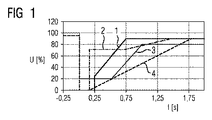
2 E.onグリッドコード
3 REEグリッドコード
4 WECCグリッドコード
5 発電機
6 第一相
7 第二相
8 第三相
9 変圧器
10 二次側
11 送電系統
12 第一の送出ライン
13 第一のスイッチ
14 負荷
15 アース
16 第二の送出ライン
17 第二のスイッチ
18 負荷
19 第三の送出ライン
20 第三のスイッチ
21 負荷
22 並列スイッチ
23 並列スイッチ
24 並列スイッチ
Claims (10)
- 障害除去時間を延長するための装置であって、
発電機(5)と、
電気負荷(14,18,21)と、
短絡事象を認識するために形成された構成部材と、
を備えており、
当該装置は、短絡時に前記電気負荷(14,18,21)が前記発電機(5)と接続されているように構成されており、
前記発電機(5)と接続されている変圧器(9)を備えており、
前記電気負荷(14,18,21)は、高圧側の変圧器中性点において、短絡パスに対して直列に設けられている、装置。 - 前記電気負荷は負荷抵抗の形態のものである、請求項1に記載の装置。
- 前記発電機(5)と接続されている変圧器(9)を備えており、
前記電気負荷(14,18,21)は前記変圧器(9)に対して並列に接続されている請求項1または2に記載の装置。 - 前記電気負荷(14,18,21)は並列に設けられたスイッチ(22,23,24)を有して形成されており、かつ前記スイッチは短絡時に開放される、請求項1に記載の装置。
- 前記発電機(5)は三相式に形成されている、請求項1から4のいずれか一項に記載の装置。
- 発電機(5)は同期発電機である、請求項1から5のいずれか一項に記載の装置。
- 消費電力系統(11)に接続されている発電機(5)において障害除去時間を延長するための方法であって、
短絡時に付加的な電気負荷(14,18,21)が接続され、
前記電気負荷(14,18,21)は変圧器中性点において短絡パスに対して直列に設けられ、かつ短絡時に前記電気負荷(14,18,21)に対して並列に設けられたスイッチが開放される、方法。 - 前記電気負荷(14,18,21)は負荷抵抗の形態のものである、請求項7に記載の方法。
- 前記電気負荷(14,18,21)は前記発電機(5)に接続されている変圧器(9)に対して並列に設けられている、請求項7または8に記載の方法。
- 発電機(5)は同期発電機である、請求項7から9のいずれか一項に記載の方法。
Applications Claiming Priority (3)
| Application Number | Priority Date | Filing Date | Title |
|---|---|---|---|
| DE102012221989 | 2012-11-30 | ||
| DE102012221989.7 | 2012-11-30 | ||
| PCT/EP2013/068385 WO2014082766A2 (de) | 2012-11-30 | 2013-09-05 | Vorrichtung und verfahren zur verlängerung der fehlerklärungszeit |
Publications (2)
| Publication Number | Publication Date |
|---|---|
| JP2015535679A JP2015535679A (ja) | 2015-12-14 |
| JP6077131B2 true JP6077131B2 (ja) | 2017-02-08 |
Family
ID=49182217
Family Applications (1)
| Application Number | Title | Priority Date | Filing Date |
|---|---|---|---|
| JP2015544384A Expired - Fee Related JP6077131B2 (ja) | 2012-11-30 | 2013-09-05 | 障害除去時間を延長するための装置および方法 |
Country Status (5)
| Country | Link |
|---|---|
| US (1) | US9564750B2 (ja) |
| EP (1) | EP2893632A2 (ja) |
| JP (1) | JP6077131B2 (ja) |
| CN (1) | CN104823375B (ja) |
| WO (1) | WO2014082766A2 (ja) |
Families Citing this family (4)
| Publication number | Priority date | Publication date | Assignee | Title |
|---|---|---|---|---|
| WO2014079453A2 (en) * | 2012-11-20 | 2014-05-30 | Vestas Wind Systems A/S | Methods and systems for reducing the impact of a generator short circuit in a wind turbine |
| WO2016146750A1 (en) * | 2015-03-17 | 2016-09-22 | Abb Technology Ag | Excitation system |
| PL3157161T3 (pl) * | 2015-10-12 | 2019-09-30 | Siemens Aktiengesellschaft | Sposób sterowania instalacją energii wiatrowej |
| CN107592045B (zh) * | 2017-10-31 | 2024-03-19 | 江苏瑞昌哥尔德发电设备股份有限公司 | 一种切换发电机电压输出的接线装置 |
Family Cites Families (28)
| Publication number | Priority date | Publication date | Assignee | Title |
|---|---|---|---|---|
| DE2115807C3 (de) * | 1971-04-01 | 1974-10-17 | Siemens Ag, 1000 Berlin Und 8000 Muenchen | Erdschlußschutzeinrichtung für elektrische Geräte mit in Stern geschalteten Wicklungen |
| NL161628C (nl) * | 1974-08-22 | 1980-02-15 | Heemaf Nv | Borstelloze draaistroomgenerator met een inrichting voor zelfbekrachtiging en automatische regeling van de bekrachtigingsstroom. |
| JPS58136299A (ja) * | 1982-02-05 | 1983-08-13 | Toshiba Corp | 超電導発電機の減磁装置 |
| US4511807A (en) * | 1982-04-20 | 1985-04-16 | Northern Engineering Industries Plc | Electrical generator control system |
| DE4307268A1 (de) * | 1993-03-02 | 1994-09-08 | Siemens Ag | Bürstenloser Synchrongenerator |
| JP2000179446A (ja) * | 1998-12-11 | 2000-06-27 | Hiroaki Sano | 小型風力発電系統連系システム及びその自動運転用保護装置 |
| DE10134883A1 (de) * | 2001-07-18 | 2003-01-30 | Abb Research Ltd | Verfahren und Vorrichtung zur drehzahlstellbaren leistungselektronischen Regelung einer getriebelosen Windkraftanlage |
| JP2003056450A (ja) * | 2001-08-09 | 2003-02-26 | Kawamura Electric Inc | 風力発電設備 |
| JP2003189697A (ja) * | 2001-12-19 | 2003-07-04 | Kokusan Denki Co Ltd | 交流発電機を備えた電源装置 |
| WO2003065567A1 (de) * | 2002-01-29 | 2003-08-07 | Vestas Wind Systems A/S | Schaltungsanordnung zum einsatz bei einer windenergieanlage |
| US7015595B2 (en) * | 2002-02-11 | 2006-03-21 | Vestas Wind Systems A/S | Variable speed wind turbine having a passive grid side rectifier with scalar power control and dependent pitch control |
| DE502005010890D1 (de) | 2004-10-28 | 2011-03-03 | Alstom Technology Ltd | Statisches erregersystem für einen generator sowie verfahren zum betrieb eines solchen erregersystems |
| US7276807B2 (en) * | 2006-01-19 | 2007-10-02 | General Electric Company | Wind turbine dump load system and method |
| DE102006010537B4 (de) * | 2006-03-07 | 2009-06-10 | Siemens Ag | Dieselelektrisches Antriebssystem mit einem permanent erregten Synchrongenerator |
| DE102006051546A1 (de) | 2006-11-02 | 2008-05-08 | Nordex Energy Gmbh | Verfahren zum Betrieb einer Windenergieanlage mit einem doppelt gespeisten Asynchrongenerator sowie Windenergieanlage mit einem doppelt gespeisten Asynchrongenerator |
| EP2392069A2 (en) * | 2009-01-30 | 2011-12-07 | DeWind Co. | Wind turbine with lvrt capabilities |
| JP5443014B2 (ja) * | 2009-02-13 | 2014-03-19 | 株式会社日立製作所 | 風力発電装置および風力発電装置の制御方法 |
| ES2325729B2 (es) * | 2009-02-19 | 2010-09-27 | Universidad Politecnica De Madrid | Sistema de desexcitacion rapida para maquinas sincronas con excitacionindirecta. |
| CN103081273B (zh) * | 2010-06-30 | 2016-05-11 | 维斯塔斯风力系统有限公司 | 风力涡轮机 |
| EP2486274B1 (en) * | 2010-11-30 | 2016-01-20 | MITSUBISHI HEAVY INDUSTRIES, Ltd. | Power generating apparatus of renewable energy type and operation method thereof |
| KR101725551B1 (ko) * | 2011-01-14 | 2017-04-11 | 매그나칩 반도체 유한회사 | 백라이트 구동회로 및 이를 적용한 디스플레이 장치 |
| EP2476900A1 (en) | 2011-01-18 | 2012-07-18 | Siemens Aktiengesellschaft | Wind turbine |
| CN202503279U (zh) * | 2012-03-26 | 2012-10-24 | 上海市电力公司 | 一种主变中性点直流电流限制装置 |
| CN102738829B (zh) * | 2012-06-30 | 2015-06-17 | 广东明阳风电产业集团有限公司 | 一种变频控制风力发电系统的拓扑结构 |
| CN102728829B (zh) | 2012-07-12 | 2014-06-18 | 安徽精诚铜业股份有限公司 | 一种合金液流量控制装置 |
| WO2014079453A2 (en) * | 2012-11-20 | 2014-05-30 | Vestas Wind Systems A/S | Methods and systems for reducing the impact of a generator short circuit in a wind turbine |
| JP2014166033A (ja) * | 2013-02-25 | 2014-09-08 | Toyota Motor Corp | 電源装置 |
| CN105637724A (zh) * | 2013-10-18 | 2016-06-01 | 维斯塔斯风力系统集团公司 | 用于风力涡轮发电机的转换器 |
-
2013
- 2013-09-05 JP JP2015544384A patent/JP6077131B2/ja not_active Expired - Fee Related
- 2013-09-05 CN CN201380062802.9A patent/CN104823375B/zh not_active Expired - Fee Related
- 2013-09-05 WO PCT/EP2013/068385 patent/WO2014082766A2/de active Application Filing
- 2013-09-05 US US14/443,387 patent/US9564750B2/en not_active Expired - Fee Related
- 2013-09-05 EP EP13762768.3A patent/EP2893632A2/de not_active Withdrawn
Also Published As
| Publication number | Publication date |
|---|---|
| EP2893632A2 (de) | 2015-07-15 |
| WO2014082766A3 (de) | 2014-08-14 |
| US20150303681A1 (en) | 2015-10-22 |
| US9564750B2 (en) | 2017-02-07 |
| JP2015535679A (ja) | 2015-12-14 |
| CN104823375B (zh) | 2017-09-12 |
| WO2014082766A2 (de) | 2014-06-05 |
| CN104823375A (zh) | 2015-08-05 |
Similar Documents
| Publication | Publication Date | Title |
|---|---|---|
| CA2822942C (en) | Alternative power converter system | |
| JP5576681B2 (ja) | 送電のための補償システム | |
| Martínez et al. | Short circuit signatures from different wind turbine generator types | |
| Skytt et al. | HVDC Light for connection of wind farms | |
| JP6077131B2 (ja) | 障害除去時間を延長するための装置および方法 | |
| Yang et al. | Multi-terminal DC wind farm collection and transmission system internal fault analysis | |
| CN110048372B (zh) | 一种改进的高压发电机定子单相接地故障保护方法 | |
| Chaudhary et al. | Control and operation of wind turbine converters during faults in an offshore wind power plant grid with VSC-HVDC connection | |
| CN104779639B (zh) | 一种变流器系统及双馈式风力发电机组 | |
| Yasa et al. | Unbalanced fault analysis of doubly fed induction generator drive system for wind turbine applications | |
| JP5401383B2 (ja) | 風力発電システム及びその制御装置 | |
| Maity et al. | Asynchronous operation of synchronous generators under field failure | |
| Zhang et al. | Novel rotor-side control scheme for doubly fed induction generator to ride through grid faults | |
| Van et al. | Voltage compensation scheme for DFIG wind turbine system to enhance low-voltage ride-through capability | |
| Awad et al. | Mitigation of switching overvoltages due to energization procedures in grid-connected offshore wind farms | |
| CN108494013B (zh) | 基于被保护对象的启机保护配置方法 | |
| El-helw et al. | Comparison study between two Dynamic Breaking resistor techniques in protecting the doubly fed induction generator | |
| Metatla et al. | Dynamic behavior of doubly fed induction generator during network voltage dips | |
| CN112909989A (zh) | 一种中压双馈风电机组及其控制方法 | |
| Ahuja et al. | Investigations on fault behaviour of grid connected DFIG based wind energy conversion systems | |
| CN219659415U (zh) | 继电保护系统及风力发电机组 | |
| Alidemaj et al. | FAULT CURRENT DUE TO ASYNCHRONOUS CONNECTION OF THE GENERATOR TO THE GRID AND IMPACT ON HV CIRCUIT BREAKER WITH GAS SF6. | |
| Saleh et al. | Impacts of grounding configurations on responses of ground protective relays for DFIG-based WECSs-part II: High-impedance ground faults | |
| Yuan et al. | A study on auto-reclosing strategy for large-scale wind farm transmission line | |
| JP2014011810A (ja) | 制御装置および可変速発電電動機始動方法 |
Legal Events
| Date | Code | Title | Description |
|---|---|---|---|
| A521 | Written amendment |
Free format text: JAPANESE INTERMEDIATE CODE: A523 Effective date: 20150708 |
|
| A621 | Written request for application examination |
Free format text: JAPANESE INTERMEDIATE CODE: A621 Effective date: 20150708 |
|
| A977 | Report on retrieval |
Free format text: JAPANESE INTERMEDIATE CODE: A971007 Effective date: 20160526 |
|
| A131 | Notification of reasons for refusal |
Free format text: JAPANESE INTERMEDIATE CODE: A131 Effective date: 20160613 |
|
| A521 | Written amendment |
Free format text: JAPANESE INTERMEDIATE CODE: A523 Effective date: 20160727 |
|
| TRDD | Decision of grant or rejection written | ||
| A01 | Written decision to grant a patent or to grant a registration (utility model) |
Free format text: JAPANESE INTERMEDIATE CODE: A01 Effective date: 20161212 |
|
| A61 | First payment of annual fees (during grant procedure) |
Free format text: JAPANESE INTERMEDIATE CODE: A61 Effective date: 20170111 |
|
| R150 | Certificate of patent or registration of utility model |
Ref document number: 6077131 Country of ref document: JP Free format text: JAPANESE INTERMEDIATE CODE: R150 |
|
| LAPS | Cancellation because of no payment of annual fees |