JP6077131B2 - Apparatus and method for extending fault removal time - Google Patents
Apparatus and method for extending fault removal time Download PDFInfo
- Publication number
- JP6077131B2 JP6077131B2 JP2015544384A JP2015544384A JP6077131B2 JP 6077131 B2 JP6077131 B2 JP 6077131B2 JP 2015544384 A JP2015544384 A JP 2015544384A JP 2015544384 A JP2015544384 A JP 2015544384A JP 6077131 B2 JP6077131 B2 JP 6077131B2
- Authority
- JP
- Japan
- Prior art keywords
- generator
- transformer
- electrical load
- load
- short circuit
- Prior art date
- Legal status (The legal status is an assumption and is not a legal conclusion. Google has not performed a legal analysis and makes no representation as to the accuracy of the status listed.)
- Expired - Fee Related
Links
Images


Classifications
-
- G—PHYSICS
- G01—MEASURING; TESTING
- G01R—MEASURING ELECTRIC VARIABLES; MEASURING MAGNETIC VARIABLES
- G01R31/00—Arrangements for testing electric properties; Arrangements for locating electric faults; Arrangements for electrical testing characterised by what is being tested not provided for elsewhere
- G01R31/50—Testing of electric apparatus, lines, cables or components for short-circuits, continuity, leakage current or incorrect line connections
- G01R31/52—Testing for short-circuits, leakage current or ground faults
-
- G—PHYSICS
- G01—MEASURING; TESTING
- G01R—MEASURING ELECTRIC VARIABLES; MEASURING MAGNETIC VARIABLES
- G01R31/00—Arrangements for testing electric properties; Arrangements for locating electric faults; Arrangements for electrical testing characterised by what is being tested not provided for elsewhere
- G01R31/34—Testing dynamo-electric machines
-
- H—ELECTRICITY
- H02—GENERATION; CONVERSION OR DISTRIBUTION OF ELECTRIC POWER
- H02H—EMERGENCY PROTECTIVE CIRCUIT ARRANGEMENTS
- H02H7/00—Emergency protective circuit arrangements specially adapted for specific types of electric machines or apparatus or for sectionalised protection of cable or line systems, and effecting automatic switching in the event of an undesired change from normal working conditions
- H02H7/06—Emergency protective circuit arrangements specially adapted for specific types of electric machines or apparatus or for sectionalised protection of cable or line systems, and effecting automatic switching in the event of an undesired change from normal working conditions for dynamo-electric generators; for synchronous capacitors
- H02H7/067—Emergency protective circuit arrangements specially adapted for specific types of electric machines or apparatus or for sectionalised protection of cable or line systems, and effecting automatic switching in the event of an undesired change from normal working conditions for dynamo-electric generators; for synchronous capacitors on occurrence of a load dump
-
- H—ELECTRICITY
- H02—GENERATION; CONVERSION OR DISTRIBUTION OF ELECTRIC POWER
- H02P—CONTROL OR REGULATION OF ELECTRIC MOTORS, ELECTRIC GENERATORS OR DYNAMO-ELECTRIC CONVERTERS; CONTROLLING TRANSFORMERS, REACTORS OR CHOKE COILS
- H02P29/00—Arrangements for regulating or controlling electric motors, appropriate for both AC and DC motors
- H02P29/02—Providing protection against overload without automatic interruption of supply
- H02P29/024—Detecting a fault condition, e.g. short circuit, locked rotor, open circuit or loss of load
- H02P29/0241—Detecting a fault condition, e.g. short circuit, locked rotor, open circuit or loss of load the fault being an overvoltage
Description
本発明は障害除去時間を延長するための装置と、障害除去時間を延長するための方法とに関する。 The present invention relates to an apparatus for extending fault removal time and a method for extending fault removal time.
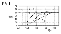
電力供給網において再生エネルギー発生装置が大きく増大していることにより、送電系統運用者が全ての給電ユニットに対して安定性と供給安全性に関して課する最小限の要求は恒常的に大きくなりつつある。このために統一的な運用を要求するグリッドコードが存在する。こうして例えばフィンランドのグリッドコードである「フィン・グリッド」では、残留電圧がゼロp.u.のとき、250msの障害除去時間が要求され、当該障害除去時間はいくつかの発電機、特に同期発電機にとっては、付加的な措置がなければ非同期に陥り、それとともに供給電圧回復後に付随的に新たな同期を行う結果を招く。図1は複数のグリッドコード要件を示している。すなわち上記の「フィン・グリッド」には参照番号1が付与されている。さらなるグリッドコード要件は本図において例えば2のE.on、3のREEスペインおよび4のWECC北米に関して示されている。
Due to the large increase in renewable energy generators in the power supply network, the minimum requirements that transmission system operators place on all power supply units regarding stability and supply safety are constantly increasing. . For this reason, there is a grid code that requires uniform operation. Thus, for example, in the “Fin Grid” which is a Finnish grid code, the residual voltage is zero p. u. In this case, a fault removal time of 250 ms is required, and for some generators, in particular synchronous generators, it will become asynchronous unless additional measures are taken, and incidentally after the supply voltage is restored. This results in a new synchronization. FIG. 1 illustrates a plurality of grid code requirements. That is,
供給電圧回復後に新たに同期を行う過程は数分を要し得、当該数分の間、発電所出力は送電系統に対して使用できない。これは特に比較的大きな発電所の障害の場合、送電系統の不安定性につながり、最悪の場合は広域の停電につながりかねない。 The new synchronization process after the supply voltage is restored can take several minutes, during which time the power plant output is not available to the transmission system. This can lead to power grid instability, especially in the case of relatively large power plant failures, and in the worst case can lead to wide-area power outages.
短絡の間、タービンを介して軸構造体に供給される機械的出力は発電機において取り出されなくなり、それによりタービン発電機の加速を生じさせる。 During the short circuit, the mechanical output supplied to the shaft structure via the turbine is no longer taken off at the generator, thereby causing acceleration of the turbine generator.
同期発電機の回転子偏位角が臨界的な過渡値を上回ると、当該同期発電機は非同期に陥り、新たに同期されなければならない。グリッドコードでは、変圧器の高圧側における所定の残留電圧の際、発電所は送電系統を遮断することなく所定の障害除去時間を経過できなければならないことが要求されている。要求される当該障害除去時間が、タービン発電機にとって実現可能な障害除去時間を上回る場合、付加的な予防措置が講じられなければならない。 When the rotor deflection angle of a synchronous generator exceeds a critical transient value, the synchronous generator falls asynchronous and must be newly synchronized. The grid code requires that the power plant must be able to pass a predetermined fault removal time without interrupting the transmission system at a predetermined residual voltage on the high voltage side of the transformer. If the required fault removal time exceeds the fault removal time achievable for the turbine generator, additional precautions must be taken.
従来技術において、上記の状況を考慮するための複数の可能性が知られている。すなわち例えば特許文献1では、障害の際、アクティブ・ブースター回路がスリップリングを介して、発電機界磁巻線に対して直列に、充電されたコンデンサに接続され、それにより界磁電圧が急激に高められる。これにより、発電機は送電系統の回復時に過励磁領域にあり、それによりタービン発電機と送電系統というシステムの安定性が増大する。
In the prior art, several possibilities for considering the above situation are known. That is, for example, in
臨界障害除去時間を延長するためのさらなる可能性は、構造体の慣性モーメントを増大させ、それにより短絡時の軸の加速を低減させることである。 A further possibility for extending the critical fault removal time is to increase the moment of inertia of the structure and thereby reduce the acceleration of the axis during short circuit.
さらに多くのタービン型式に対して、蒸気タービンに変更を実施し、それによりタービン翼と水蒸気との接続をより迅速に断つことを実現する可能性があり、これはファースト・バルビングと称される。これにより、軸構造体に供給されるタービン出力のより迅速な低減を実現しようとするものである。 For even more turbine types, it is possible to make changes to the steam turbine, thereby realizing a quicker disconnect between the turbine blades and the steam, which is referred to as fast valve. Thereby, it is going to implement | achieve quicker reduction of the turbine output supplied to a shaft structure.
同様に、洋上風力発電所において、負荷抵抗を用いて類似のコンセプトを形にすることが知られている。ウィンドパークはしかしながら、例えば高圧DC接続を介して陸上コンバータ設備と接続され、当該陸上コンバータ設備は陸上での短絡時に、ウィンドパークの過剰なエネルギーを負荷抵抗に導く。 Similarly, it is known to use load resistance to shape a similar concept in offshore wind farms. The wind park, however, is connected to the onshore converter facility, for example via a high voltage DC connection, which leads the excess energy of the wind park to the load resistance in the event of a short circuit on land.
タービン発電機のための、短絡時の障害除去時間を延長するための簡単な可能性を有することは望ましい。 It would be desirable to have a simple possibility to extend the fault removal time during a short circuit for a turbine generator.
本発明は上記の点を対象としており、本発明の課題は障害除去時間を延長するための装置および方法を記載することである。 The present invention is directed to the above points, and an object of the present invention is to describe an apparatus and method for extending fault removal time.
上記の課題は障害除去時間を延長するための装置であって、発電機、特に同期発電機と、電気負荷と、短絡事象を認識するために形成された構成部材とを有する装置によって解決され、当該装置は、短絡時に前記電気負荷が前記発電機と接続されているように形成されている。 The above problem is solved by an apparatus for extending fault removal time, which comprises a generator, in particular a synchronous generator, an electrical load, and a component formed to recognize a short circuit event, The device is configured such that the electrical load is connected to the generator during a short circuit.
本発明により好適に、機械的な介入を行うことなく、所与の軸構造体もしくは当該軸構造体の構成要素に変更を行うことが実現される。 The present invention preferably implements a change to a given shaft structure or a component of the shaft structure without mechanical intervention.
第一の有利なさらなる構成において、電気負荷は抵抗として形成されている。これにより以下の思想が追及される。すなわち、短絡時に電気負荷として発電機に接続されている抵抗を設け、このように障害時に発電機を送電系統から分離することなく、軸の加速をもたらすタービン出力を逃がす接続可能な負荷抵抗として前記抵抗を設けるという思想である。これにより臨界障害除去時間は著しく延長される。 In a first advantageous further configuration, the electrical load is formed as a resistor. As a result, the following ideas are pursued. That is, the resistance connected to the generator as an electrical load at the time of a short circuit is provided, and thus the connectable load resistance that escapes the turbine output that causes acceleration of the shaft without separating the generator from the power transmission system at the time of failure as described above The idea is to provide resistance. This significantly extends the critical fault removal time.
有利なさらなる構成は従属請求項に記載されている。すなわち一の有利なさらなる構成において前記装置は、発電機と接続されている変圧器を有して形成されており、電気負荷は短絡の間、変圧器に対して並列に設けられている。 Advantageous further configurations are described in the dependent claims. That is, in one advantageous further configuration, the device is formed with a transformer connected to the generator, and the electrical load is provided in parallel to the transformer during a short circuit.
代替的な実施の形態において前記装置は電気負荷を有して形成されており、当該電気負荷は短絡パスに対して直列に、高圧側の変圧器中性点に設けられている。 In an alternative embodiment, the device is formed with an electrical load, which is provided in series with the short-circuit path at the transformer neutral point on the high-voltage side.
上記の接続可能な抵抗のさらなる潜在的な応用として、発電機回路遮断器の負荷を著しく除去することが実現可能である。 As a further potential application of the above connectable resistor, it is feasible to significantly remove the load on the generator circuit breaker.
発電機回路遮断器の設計に対しては、短絡時に当該発電機回路遮断器をできる限り迅速に遮断することを要求される場合が多い。
突然に生じる発電機短絡は、交流成分と直流成分とから合成され、当該交流成分と直流成分は当該交流成分と直流成分の時間定数に応じて、異なる速さで固定的な短絡電流に減衰する。特に短絡電流の直流成分は、電流経過が数ミリ秒後に初めて電流ゼロ点通過を経験することの原因となっている。回路遮断器の開放後、スイッチングアークは当該最初の電流ゼロ点通過が起こり、アークが消失し得るまで燃焼する。この時間内に遮断器では極めて高温のアークプラズマのために、著しい接触負荷と発熱が生じる。従って短絡電流の直流成分はできる限り迅速に減衰することが望ましい。
時間定数(T)は基本的に、短絡パスに設けられているインダクタンス(L)と、短絡パスにおいて有効な抵抗(R)との比を介して記述される。式T=L/Rを介して、以下の点が明らかとなる。すなわち、有効な抵抗が大きくなるにつれて、時間定数は低下させられ得る。これは本願で説明される負荷抵抗を、障害発生後に接続することにより、有効に加速される。
The design of a generator circuit breaker is often required to shut off the generator circuit breaker as quickly as possible in the event of a short circuit.
A sudden generator short-circuit is synthesized from an AC component and a DC component, and the AC component and the DC component are attenuated to a fixed short-circuit current at different speeds according to the time constant of the AC component and the DC component. . In particular, the DC component of the short-circuit current is the cause of the current passing through the zero point of current for the first time after several milliseconds. After opening the circuit breaker, the switching arc burns until the first current zero point occurs and the arc can disappear. Within this time, the circuit breaker generates a significant contact load and heat generation due to the extremely hot arc plasma. Therefore, it is desirable to attenuate the DC component of the short-circuit current as quickly as possible.
The time constant (T) is basically described through the ratio of the inductance (L) provided in the short circuit path and the resistance (R) effective in the short circuit path. The following points become clear through the formula T = L / R. That is, the time constant can be reduced as the effective resistance increases. This is effectively accelerated by connecting the load resistance described herein after the failure.
前記課題はまた、障害除去時間を延長するための方法によって解決され、当該方法において消費電力系統に接続された発電機には短絡時に、付加的な電気負荷が接続される。 The problem is also solved by a method for extending the fault removal time, wherein an additional electrical load is connected to the generator connected to the power consumption system in the case of a short circuit.
ここで本発明を実施の形態に基づいてより詳しく説明する。図2と図3が概略的に示すのは以下の通りである。 Here, the present invention will be described in more detail based on the embodiments. 2 and 3 schematically show the following.
図2は三相発電機5、特に同期発電機を示しており、出力部に第一相6と、第二相7と、第三相8とが形成されている。第一相6と、第二相7と、第三相8とは変圧器9に接続される。変圧器9の二次側10は送電系統11に接続される。第一相6において第一の送出ライン12が設けられており、当該第一の送出ラインに第一のスイッチ13と電気負荷14が接続され、アース15に接続されている。第二相7は第二の送出ライン16と、当該第二の送出ライン16に接続されている第二のスイッチ17と、アース15に接続された負荷18とを含んでいる。第三相8は第三の送出ライン19と、相応の第三のスイッチ20と、負荷21とを含んでおり、当該負荷もアース15に接続されている。
FIG. 2 shows a three-
相6,7および8はこのとき発電機スイッチ25を介して変圧器9に接続される。
図3は本発明の代替的な実施の形態を示している。図2との違いは、負荷14,18および21が、短絡パスに対して直列に、高圧側の変圧器中性点に設けられている点である。負荷14,18および21に対して並列に、それぞれスイッチ22,23および24が設けられている。
FIG. 3 shows an alternative embodiment of the present invention. The difference from FIG. 2 is that the
発電機5はタービン(図に示されていない)を介して駆動される。障害時に軸に供給されるタービン出力は送電系統が回復するまで、発電機5により接続可能な負荷14,18,21を介して接続され、熱に変換される。言い換えると、障害時、接続可能な負荷14,18,21を介して、軸に供給されるタービン出力は送電系統が回復するまで、発電機5から電気的に取り出され、熱に変換される。障害時間の間、発電機5は送電系統11と接続されたままである。これにより、送電系統を新たに同期させることが不要となり、発電所の利用可能性が高められ得る。付加的な負荷なしの個々の構造体に関する臨界障害除去時間TKUは、一般的に以下の式に応じて分析的に規定される。
The

上記の式において表されるのは以下の通りである。
ω0 定格角周波数
J 構造体全体の慣性モーメント
δ′Ku タービン発電機の安定性を得るまでの最大の過渡的電圧角度
δ′0 短絡発生前の過渡的電圧角度
PT タービン出力
What is represented in the above formula is as follows.
ω 0 Rated angular frequency J Moment of inertia of the entire structure δ ′ Maximum transient voltage angle δ ′ 0 until obtaining stability of Ku turbine generator Transient voltage angle PT turbine output before occurrence of short circuit
電気抵抗として形成されていてよい負荷14,18および21は、障害時に軸の加速をもたらすタービン出力を逃がし、これにより臨界障害除去時間は著しく延長され、それにより短絡時に接続可能な負荷抵抗14,18および21を介して、発電機5、特に同期発電機の過渡安定度を増大させる。図2に示される負荷抵抗14,18および21は変圧器9に対して並列に、変圧器の低圧側に設けられており、それにより変圧器縦方向インピーダンスを介して、短絡時に存在する短絡残留電圧を用いる。調整可能なリアクタンスを付加的に用いると、回路の反応度をさらに向上させることができる。
図2は本発明の第一の実施の形態についてのトポロジーを示している。 FIG. 2 shows the topology for the first embodiment of the present invention.
第二の実施の形態のトポロジーは図3に示される。負荷抵抗14,18および21は短絡パスに対して直列に、高圧側の変圧器中性点に設けられている。当該負荷抵抗は並列スイッチ22,23,24を開放することにより、短絡回路内に接続される。
The topology of the second embodiment is shown in FIG. The load resistors 14, 18 and 21 are provided in series with the short-circuit path at the transformer neutral point on the high voltage side. The load resistor is connected in the short circuit by opening the
障害事象における発電機5のための臨界障害除去時間はこのように好適な方法で、変圧器低圧側でも変圧器高圧側でも増大させられる。接続可能なリアクタンスもしくは調整可能なリアクタンスによって回路トポロジーを拡大することにより、障害除去時間をさらに増大させることができる。
The critical fault removal time for the
本発明によりこのように、タービンおよび発電機5に構成技術上の変更を実施する必要なしに、臨界障害除去時間は著しく増大され得、それにより本願で説明される発明の廉価な手段を成立させる。さらに、時間的に限定された短絡の間に送電系統を遮断する必要がなく、それにより新たな同期を行うことのない発電機5の恒常的な利用可能性を実現することができる。
In this way, the critical fault removal time can thus be significantly increased without having to make any structural changes to the turbine and
1 フィン・グリッド
2 E.onグリッドコード
3 REEグリッドコード
4 WECCグリッドコード
5 発電機
6 第一相
7 第二相
8 第三相
9 変圧器
10 二次側
11 送電系統
12 第一の送出ライン
13 第一のスイッチ
14 負荷
15 アース
16 第二の送出ライン
17 第二のスイッチ
18 負荷
19 第三の送出ライン
20 第三のスイッチ
21 負荷
22 並列スイッチ
23 並列スイッチ
24 並列スイッチ
1 Fin Grid 2 E. on grid cord 3 REE grid cord 4
Claims (10)
発電機(5)と、
電気負荷(14,18,21)と、
短絡事象を認識するために形成された構成部材と、
を備えており、
当該装置は、短絡時に前記電気負荷(14,18,21)が前記発電機(5)と接続されているように構成されており、
前記発電機(5)と接続されている変圧器(9)を備えており、
前記電気負荷(14,18,21)は、高圧側の変圧器中性点において、短絡パスに対して直列に設けられている、装置。 A device for extending the obstacle removal time,
A generator (5),
Electrical loads (14, 18, 21);
A component formed to recognize a short circuit event;
With
The device is configured such that the electrical load (14, 18, 21) is connected to the generator (5) during a short circuit ,
A transformer (9) connected to the generator (5),
The electrical load (14, 18, 21) is a device provided in series with the short-circuit path at the transformer neutral point on the high voltage side .
前記電気負荷(14,18,21)は前記変圧器(9)に対して並列に接続されている請求項1または2に記載の装置。 A transformer (9) connected to the generator (5),
Device according to claim 1 or 2, wherein the electrical load (14, 18, 21) is connected in parallel to the transformer (9).
短絡時に付加的な電気負荷(14,18,21)が接続され、
前記電気負荷(14,18,21)は変圧器中性点において短絡パスに対して直列に設けられ、かつ短絡時に前記電気負荷(14,18,21)に対して並列に設けられたスイッチが開放される、方法。 A method for extending fault removal time in a generator (5) connected to a power consumption system (11),
In the event of a short circuit, additional electrical loads (14, 18, 21) are connected ,
The electrical load (14, 18, 21) is provided in series with the short-circuit path at the transformer neutral point, and a switch provided in parallel with the electrical load (14, 18, 21) at the time of the short circuit. Open the way.
Applications Claiming Priority (3)
| Application Number | Priority Date | Filing Date | Title |
|---|---|---|---|
| DE102012221989.7 | 2012-11-30 | ||
| DE102012221989 | 2012-11-30 | ||
| PCT/EP2013/068385 WO2014082766A2 (en) | 2012-11-30 | 2013-09-05 | Device and method for increasing fault clearing time |
Publications (2)
| Publication Number | Publication Date |
|---|---|
| JP2015535679A JP2015535679A (en) | 2015-12-14 |
| JP6077131B2 true JP6077131B2 (en) | 2017-02-08 |
Family
ID=49182217
Family Applications (1)
| Application Number | Title | Priority Date | Filing Date |
|---|---|---|---|
| JP2015544384A Expired - Fee Related JP6077131B2 (en) | 2012-11-30 | 2013-09-05 | Apparatus and method for extending fault removal time |
Country Status (5)
| Country | Link |
|---|---|
| US (1) | US9564750B2 (en) |
| EP (1) | EP2893632A2 (en) |
| JP (1) | JP6077131B2 (en) |
| CN (1) | CN104823375B (en) |
| WO (1) | WO2014082766A2 (en) |
Families Citing this family (4)
| Publication number | Priority date | Publication date | Assignee | Title |
|---|---|---|---|---|
| EP2923441B1 (en) * | 2012-11-20 | 2019-01-09 | Vestas Wind Systems A/S | Methods and systems for reducing the impact of a generator short circuit in a wind turbine |
| EP3271984B1 (en) * | 2015-03-17 | 2020-05-06 | ABB Schweiz AG | Excitation system with a protection device against an arc fault |
| DK3157161T3 (en) * | 2015-10-12 | 2019-05-20 | Siemens Ag | WIND POWER INSTALLATION PROCEDURE |
| CN107592045B (en) * | 2017-10-31 | 2024-03-19 | 江苏瑞昌哥尔德发电设备股份有限公司 | Wiring device for switching voltage output of generator |
Family Cites Families (28)
| Publication number | Priority date | Publication date | Assignee | Title |
|---|---|---|---|---|
| DE2115807C3 (en) * | 1971-04-01 | 1974-10-17 | Siemens Ag, 1000 Berlin Und 8000 Muenchen | Earth fault protection device for electrical devices with star-connected windings |
| NL161628C (en) * | 1974-08-22 | 1980-02-15 | Heemaf Nv | BRUSHLESS AC POWER GENERATOR WITH SELF-POWERED DEVICE AND AUTOMATIC POWER RATE CONTROL. |
| JPS58136299A (en) | 1982-02-05 | 1983-08-13 | Toshiba Corp | Demagnetizing device for superconductive generator |
| US4511807A (en) * | 1982-04-20 | 1985-04-16 | Northern Engineering Industries Plc | Electrical generator control system |
| DE4307268A1 (en) * | 1993-03-02 | 1994-09-08 | Siemens Ag | Brushless synchronous generator |
| JP2000179446A (en) * | 1998-12-11 | 2000-06-27 | Hiroaki Sano | Small-size wind power generating system interconnection system and protecting device for its automatic drive |
| DE10134883A1 (en) * | 2001-07-18 | 2003-01-30 | Abb Research Ltd | Method and device for speed-adjustable power electronic control of a gearless wind turbine |
| JP2003056450A (en) | 2001-08-09 | 2003-02-26 | Kawamura Electric Inc | Wind power generation equipment |
| JP2003189697A (en) * | 2001-12-19 | 2003-07-04 | Kokusan Denki Co Ltd | Power supply provided with alternating-current generator |
| US7102247B2 (en) * | 2002-01-29 | 2006-09-05 | Vestas Wind Systems A/S | Circuit arrangement and methods for use in a wind energy installation |
| US7015595B2 (en) * | 2002-02-11 | 2006-03-21 | Vestas Wind Systems A/S | Variable speed wind turbine having a passive grid side rectifier with scalar power control and dependent pitch control |
| DE502005010890D1 (en) | 2004-10-28 | 2011-03-03 | Alstom Technology Ltd | STATIC EXTRACTION SYSTEM FOR A GENERATOR AND METHOD FOR OPERATING SUCH AN EXTRACTION SYSTEM |
| US7276807B2 (en) * | 2006-01-19 | 2007-10-02 | General Electric Company | Wind turbine dump load system and method |
| DE102006010537B4 (en) | 2006-03-07 | 2009-06-10 | Siemens Ag | Diesel-electric drive system with a permanently excited synchronous generator |
| DE102006051546A1 (en) * | 2006-11-02 | 2008-05-08 | Nordex Energy Gmbh | Method for operating a wind turbine with a double-fed asynchronous generator and wind turbine with a double-fed asynchronous generator |
| US20120104754A1 (en) * | 2009-01-30 | 2012-05-03 | Georg Rudolf | Wind turbine with lvrt capabilities |
| JP5443014B2 (en) * | 2009-02-13 | 2014-03-19 | 株式会社日立製作所 | Wind power generator and control method of wind power generator |
| ES2325729B2 (en) * | 2009-02-19 | 2010-09-27 | Universidad Politecnica De Madrid | QUICK DEEXCITATION SYSTEM FOR SYNCHRONOUS MACHINES WITH INDIRECT EXCITATION. |
| WO2012000508A2 (en) * | 2010-06-30 | 2012-01-05 | Vestas Wind Systems A/S | Wind turbine |
| CN102985686A (en) * | 2010-11-30 | 2013-03-20 | 三菱重工业株式会社 | Power generating apparatus of renewable energy type and operation method thereof |
| KR101725551B1 (en) * | 2011-01-14 | 2017-04-11 | 매그나칩 반도체 유한회사 | Backlight driving circuit and Display apparatus |
| EP2476900A1 (en) * | 2011-01-18 | 2012-07-18 | Siemens Aktiengesellschaft | Wind turbine |
| CN202503279U (en) * | 2012-03-26 | 2012-10-24 | 上海市电力公司 | Direct current limiting device for neutral point of main transformer |
| CN102738829B (en) * | 2012-06-30 | 2015-06-17 | 广东明阳风电产业集团有限公司 | Topological structure of variable frequency control wind power generation system |
| CN102728829B (en) | 2012-07-12 | 2014-06-18 | 安徽精诚铜业股份有限公司 | Flow control device for alloy liquid |
| EP2923441B1 (en) * | 2012-11-20 | 2019-01-09 | Vestas Wind Systems A/S | Methods and systems for reducing the impact of a generator short circuit in a wind turbine |
| JP2014166033A (en) * | 2013-02-25 | 2014-09-08 | Toyota Motor Corp | Power unit |
| WO2015055211A1 (en) * | 2013-10-18 | 2015-04-23 | Vestas Wind Systems A/S | Converters for wind turbine generators |
-
2013
- 2013-09-05 WO PCT/EP2013/068385 patent/WO2014082766A2/en active Application Filing
- 2013-09-05 EP EP13762768.3A patent/EP2893632A2/en not_active Withdrawn
- 2013-09-05 JP JP2015544384A patent/JP6077131B2/en not_active Expired - Fee Related
- 2013-09-05 US US14/443,387 patent/US9564750B2/en not_active Expired - Fee Related
- 2013-09-05 CN CN201380062802.9A patent/CN104823375B/en not_active Expired - Fee Related
Also Published As
| Publication number | Publication date |
|---|---|
| CN104823375B (en) | 2017-09-12 |
| US9564750B2 (en) | 2017-02-07 |
| WO2014082766A3 (en) | 2014-08-14 |
| CN104823375A (en) | 2015-08-05 |
| WO2014082766A2 (en) | 2014-06-05 |
| JP2015535679A (en) | 2015-12-14 |
| EP2893632A2 (en) | 2015-07-15 |
| US20150303681A1 (en) | 2015-10-22 |
Similar Documents
| Publication | Publication Date | Title |
|---|---|---|
| CA2822942C (en) | Alternative power converter system | |
| JP5576681B2 (en) | Compensation system for power transmission | |
| Martínez et al. | Short circuit signatures from different wind turbine generator types | |
| Skytt et al. | HVDC Light for connection of wind farms | |
| JP6077131B2 (en) | Apparatus and method for extending fault removal time | |
| Yang et al. | Multi-terminal DC wind farm collection and transmission system internal fault analysis | |
| CN110048372B (en) | Improved high-voltage generator stator single-phase earth fault protection method | |
| Chaudhary et al. | Control and operation of wind turbine converters during faults in an offshore wind power plant grid with VSC-HVDC connection | |
| CN104779639B (en) | A kind of converter system and double-feedback aerogenerator group | |
| Yasa et al. | Unbalanced fault analysis of doubly fed induction generator drive system for wind turbine applications | |
| JP5401383B2 (en) | Wind power generation system and control device therefor | |
| Maity et al. | Asynchronous operation of synchronous generators under field failure | |
| Zhang et al. | Novel rotor-side control scheme for doubly fed induction generator to ride through grid faults | |
| Van et al. | Voltage compensation scheme for DFIG wind turbine system to enhance low-voltage ride-through capability | |
| Awad et al. | Mitigation of switching overvoltages due to energization procedures in grid-connected offshore wind farms | |
| CN108494013B (en) | Start-up protection configuration method based on protected object | |
| El-helw et al. | Comparison study between two Dynamic Breaking resistor techniques in protecting the doubly fed induction generator | |
| Metatla et al. | Dynamic behavior of doubly fed induction generator during network voltage dips | |
| Ahuja et al. | Investigations on fault behaviour of grid connected DFIG based wind energy conversion systems | |
| CN219659415U (en) | Relay protection system and wind generating set | |
| Alidemaj et al. | FAULT CURRENT DUE TO ASYNCHRONOUS CONNECTION OF THE GENERATOR TO THE GRID AND IMPACT ON HV CIRCUIT BREAKER WITH GAS SF6. | |
| Saleh et al. | Impacts of grounding configurations on responses of ground protective relays for DFIG-based WECSs-part II: High-impedance ground faults | |
| Yuan et al. | A study on auto-reclosing strategy for large-scale wind farm transmission line | |
| JP2014011810A (en) | Control device and variable speed generator motor starting method | |
| Saleh et al. | Influences of power electronic converters on current-voltage behaviors during faults in DGUs-Part I: Wind energy conversion systems |
Legal Events
| Date | Code | Title | Description |
|---|---|---|---|
| A521 | Written amendment |
Free format text: JAPANESE INTERMEDIATE CODE: A523 Effective date: 20150708 |
|
| A621 | Written request for application examination |
Free format text: JAPANESE INTERMEDIATE CODE: A621 Effective date: 20150708 |
|
| A977 | Report on retrieval |
Free format text: JAPANESE INTERMEDIATE CODE: A971007 Effective date: 20160526 |
|
| A131 | Notification of reasons for refusal |
Free format text: JAPANESE INTERMEDIATE CODE: A131 Effective date: 20160613 |
|
| A521 | Written amendment |
Free format text: JAPANESE INTERMEDIATE CODE: A523 Effective date: 20160727 |
|
| TRDD | Decision of grant or rejection written | ||
| A01 | Written decision to grant a patent or to grant a registration (utility model) |
Free format text: JAPANESE INTERMEDIATE CODE: A01 Effective date: 20161212 |
|
| A61 | First payment of annual fees (during grant procedure) |
Free format text: JAPANESE INTERMEDIATE CODE: A61 Effective date: 20170111 |
|
| R150 | Certificate of patent or registration of utility model |
Ref document number: 6077131 Country of ref document: JP Free format text: JAPANESE INTERMEDIATE CODE: R150 |
|
| LAPS | Cancellation because of no payment of annual fees |