JP6076314B2 - Reducer lubrication structure - Google Patents
Reducer lubrication structure Download PDFInfo
- Publication number
- JP6076314B2 JP6076314B2 JP2014221108A JP2014221108A JP6076314B2 JP 6076314 B2 JP6076314 B2 JP 6076314B2 JP 2014221108 A JP2014221108 A JP 2014221108A JP 2014221108 A JP2014221108 A JP 2014221108A JP 6076314 B2 JP6076314 B2 JP 6076314B2
- Authority
- JP
- Japan
- Prior art keywords
- reduction gear
- lubricating oil
- case
- oil
- rib
- Prior art date
- Legal status (The legal status is an assumption and is not a legal conclusion. Google has not performed a legal analysis and makes no representation as to the accuracy of the status listed.)
- Active
Links
Images


Classifications
-
- F—MECHANICAL ENGINEERING; LIGHTING; HEATING; WEAPONS; BLASTING
- F16—ENGINEERING ELEMENTS AND UNITS; GENERAL MEASURES FOR PRODUCING AND MAINTAINING EFFECTIVE FUNCTIONING OF MACHINES OR INSTALLATIONS; THERMAL INSULATION IN GENERAL
- F16H—GEARING
- F16H57/00—General details of gearing
- F16H57/04—Features relating to lubrication or cooling or heating
- F16H57/042—Guidance of lubricant
- F16H57/0421—Guidance of lubricant on or within the casing, e.g. shields or baffles for collecting lubricant, tubes, pipes, grooves, channels or the like
- F16H57/0424—Lubricant guiding means in the wall of or integrated with the casing, e.g. grooves, channels, holes
-
- F—MECHANICAL ENGINEERING; LIGHTING; HEATING; WEAPONS; BLASTING
- F16—ENGINEERING ELEMENTS AND UNITS; GENERAL MEASURES FOR PRODUCING AND MAINTAINING EFFECTIVE FUNCTIONING OF MACHINES OR INSTALLATIONS; THERMAL INSULATION IN GENERAL
- F16H—GEARING
- F16H57/00—General details of gearing
- F16H57/04—Features relating to lubrication or cooling or heating
- F16H57/042—Guidance of lubricant
- F16H57/0421—Guidance of lubricant on or within the casing, e.g. shields or baffles for collecting lubricant, tubes, pipes, grooves, channels or the like
-
- F—MECHANICAL ENGINEERING; LIGHTING; HEATING; WEAPONS; BLASTING
- F16—ENGINEERING ELEMENTS AND UNITS; GENERAL MEASURES FOR PRODUCING AND MAINTAINING EFFECTIVE FUNCTIONING OF MACHINES OR INSTALLATIONS; THERMAL INSULATION IN GENERAL
- F16H—GEARING
- F16H57/00—General details of gearing
- F16H57/04—Features relating to lubrication or cooling or heating
- F16H57/045—Lubricant storage reservoirs, e.g. reservoirs in addition to a gear sump for collecting lubricant in the upper part of a gear case
-
- F—MECHANICAL ENGINEERING; LIGHTING; HEATING; WEAPONS; BLASTING
- F16—ENGINEERING ELEMENTS AND UNITS; GENERAL MEASURES FOR PRODUCING AND MAINTAINING EFFECTIVE FUNCTIONING OF MACHINES OR INSTALLATIONS; THERMAL INSULATION IN GENERAL
- F16H—GEARING
- F16H57/00—General details of gearing
- F16H57/04—Features relating to lubrication or cooling or heating
- F16H57/0457—Splash lubrication
-
- F—MECHANICAL ENGINEERING; LIGHTING; HEATING; WEAPONS; BLASTING
- F16—ENGINEERING ELEMENTS AND UNITS; GENERAL MEASURES FOR PRODUCING AND MAINTAINING EFFECTIVE FUNCTIONING OF MACHINES OR INSTALLATIONS; THERMAL INSULATION IN GENERAL
- F16H—GEARING
- F16H57/00—General details of gearing
- F16H57/04—Features relating to lubrication or cooling or heating
- F16H57/0467—Elements of gearings to be lubricated, cooled or heated
- F16H57/0469—Bearings or seals
- F16H57/0471—Bearing
Description
本発明は、減速機の潤滑構造に係り、特に駆動源の出力軸と連動して回転する減速ギヤをケース内に備え、該ケース内の底部に貯留される潤滑油を前記減速ギヤにて掻き上げてキャッチタンクへ導き、そのキャッチタンクから潤滑油の供給対象例えば被潤滑部あるいは被冷却部へ潤滑油を供給する減速機の潤滑構造に関するものである。 The present invention relates to a reduction gear lubrication structure, and in particular, a reduction gear that rotates in conjunction with an output shaft of a drive source is provided in a case, and lubricating oil stored in a bottom portion of the case is scraped by the reduction gear. raised and leads to Kyatchita down click, it relates to a lubricating structure of the reduction gear supplies lubricating oil from the catch tank to a supply target for example the lubricated portion or the cooled portion of the lubricating oil.
キャッチタンクに潤滑油が溜まるまで被潤滑部の各部に潤滑油が供給されないため、潤滑油の供給が、開始されるまでに時間を要していた。そのため、潤滑油の供給対象に迅速に潤滑油を供給するために、掻き上げられた潤滑油をキャッチタンクに導く開口部がキャッチタンクの上部に設けられ、その開口部よりも下方にキャッチタンクから潤滑油の供給対象に潤滑油を供給する供給口を設け、開口部と供給口との間に設けられて開口部から供給口に潤滑油を導くガイド部材とを備えて、キャッチタンク内の潤滑油の油面が、供給口に達するよりも前にガイド部材によって潤滑油を供給口に導くことにより、潤滑油の供給対象に迅速に潤滑油を供給することができる構造が知られている(例えば、特許文献1参照)。 Since the lubricating oil is not supplied to each part of the lubricated part until the lubricating oil is collected in the catch tank, it takes time until the supply of the lubricating oil is started. Therefore, in order to supply the lubricating oil quickly to the supply target of the lubricating oil, an opening for guiding the scraped-up lubricating oil to the catch tank is provided in the upper part of the catch tank, and the catch tank is below the opening. Lubricating oil in the catch tank is provided with a supply port for supplying the lubricant to the supply target of the lubricant, and a guide member provided between the opening and the supply port for guiding the lubricant from the opening to the supply port. A structure is known in which the lubricating oil can be quickly supplied to the supply target of the lubricating oil by guiding the lubricating oil to the supplying port by the guide member before the oil level reaches the supplying port ( For example, see Patent Document 1).
しかしながら、上述の構造では、たとえガイド部材を備えても、掻き上げられた潤滑油の内、キャッチタンクの開口部から供給口へ導かれた潤滑油のみを利用できるにすぎず、又、潤滑油は、キャッチタンクを経由せねばならないため、潤滑油の供給対象に潤滑油が供給されるには、依然、時間を要していた。 However, in the above-described structure, even if the guide member is provided, only the lubricating oil led up to the supply port from the opening of the catch tank can be used among the lubricating oil scraped up. However, since it has to go through a catch tank, it still takes time to supply the lubricant to the lubricant supply target.
本発明は上記事情に鑑みてなされたもので、掻き上げられた潤滑油が、キャッチタンクを経由することなく、潤滑油の供給対象に迅速に供給できる減速機の潤滑構造を提供することを目的とする。 The present invention has been made in view of the above circumstances, and it is an object of the present invention to provide a reduction gear lubrication structure capable of rapidly supplying the scraped lubricating oil to a lubricant supply target without passing through a catch tank. And
上記の課題を解決するため、請求項1に係る減速機の潤滑構造は、内部に形成される側壁と回転軸線との間に潤滑油供給対象が設けられるケースと、前記ケース内に設けられ、駆動源の出力軸と連結され、前記回転軸線回りで回転する減速ギヤと、前記ケースの底部に貯溜され前記減速ギヤにより掻き上げられて潤滑油の一部を貯溜するキャッチタンクと、前記側壁に設けられ、前記減速ギヤにより掻き上げられた潤滑油を前記キャッチタンクへ導く油路と、前記油路の背面側で前記側壁に径方向に延在して形成され、前記減速ギヤにより掻き上げられた潤滑油の内、掻き上げ高さが低く前記油路に到達できなかった潤滑油を内径方向へと導くリブと、前記側壁の前記リブの端縁に設けられ、前記リブにて捕捉された前記潤滑油が導入されて前記キャッチタンクを経由することなく前記潤滑油供給対象に供給する溝部と、前記減速ギヤの回転方向において、前記リブより手前に少なくとも1つ放射状に形成された補助リブと、を備え、前記側壁は、前記減速ギヤから離れるにつれて前記回転軸線に近づくテーパ形状に形成されたことを要旨とする。 In order to solve the above-described problem, the lubrication structure of the speed reducer according to claim 1 is provided in a case in which a lubricating oil supply target is provided between a side wall formed inside and a rotation axis, A reduction gear that is connected to the output shaft of the drive source and rotates around the rotation axis, a catch tank that is stored at the bottom of the case and is scraped up by the reduction gear and stores a part of the lubricating oil, and the side wall An oil passage that is provided and guides the lubricating oil scraped up by the reduction gear to the catch tank; and is formed to extend radially on the side wall on the back side of the oil passage, and is scraped up by the reduction gear. was among the lubricating oil, and a rib for guiding the lubricating oil height splashed could not reach the oil passage as low as radially inward, is provided on the edge of the rib of the side wall, it is caught by the rib wherein lubricating oil is introduced A groove for supplying the lubricant oil supply target without passing through the serial catch tank, in the direction of rotation of the reduction gear, and an auxiliary rib formed on at least one radially in front of the ribs, said side walls The gist of the present invention is that the taper is formed so as to approach the rotation axis as the distance from the reduction gear increases .
これによれば、減速ギヤにより掻き上げられた潤滑油が、キャッチタンクを経由することなく、リブにより潤滑油供給対象に迅速に供給される。又、減速ギヤにより掻き上げられても、従来はキャッチタンクへ到達できずにケース底部へ棄てられていた潤滑油が、潤滑油供給対象に供給できるため、潤滑油の有効活用ができる。
減速ギヤの回転方向において、リブより手前に少なくとも1つ放射状に補助リブが形成され、側壁は、減速ギヤから離れるにつれて回転軸線に近づくテーパ形状に形成される。これにより、減速ギヤにて掻き上げられた潤滑油の内、掻き上げ高さが低く油路に到達できなかった潤滑油を補助リブにても回転が規制されて捕捉できる。補助リブにて捕捉された潤滑油は、補助リブ及び側壁のテーパ形状の壁面に沿って回転軸線側に流れ、また補助リブを乗り越えてリブに到達した潤滑油は、リブにて回転が規制されリブに沿って回転軸線側に流れて、潤滑油供給対象に供給されて潤滑する。従って、減速ギヤにて掻き上げられた潤滑油の内、掻き上げ高さが低く油路に到達できなかった潤滑油の捕捉を補助リブにより向上して、潤滑油を潤滑油供給対象に供給できる。
According to this, the lubricating oil scraped up by the reduction gear is quickly supplied to the lubricating oil supply target by the rib without passing through the catch tank. Further, even if the gear is scraped up by the reduction gear, the lubricating oil that has been conventionally discarded to the bottom of the case without reaching the catch tank can be supplied to the lubricating oil supply target, so that the lubricating oil can be effectively utilized.
In the rotation direction of the reduction gear, at least one auxiliary rib is formed radially before the rib, and the side wall is formed in a tapered shape that approaches the rotation axis as the distance from the reduction gear increases. As a result, among the lubricating oil that has been scraped up by the reduction gear, the rotational speed of the lubricating oil that has been low and that could not reach the oil passage is restricted and captured even by the auxiliary rib. The lubricating oil captured by the auxiliary rib flows to the rotation axis along the auxiliary rib and the tapered wall surface of the side wall, and the lubricating oil that has reached the rib over the auxiliary rib is restricted from rotating by the rib. It flows along the rib toward the rotation axis, and is supplied to the lubricant supply object to be lubricated. Therefore, among the lubricants that have been scraped up by the reduction gear, it is possible to improve the trapping of the lubricant that has not been able to reach the oil passage with a low scraping height, and supply the lubricant to the lubricant supply target. .
この発明の実施の形態について一実施形態を図面を参照して詳細に説明する。なお、以下の実施形態において図は適宜簡略化或いは変形されており、各部の寸法比及び形状等は必ずしも正確に描かれていない。又、以下で参照する図面では、同一またはそれに相当する部材には、同じ番号が付されている。 An embodiment of the present invention will be described in detail with reference to the drawings. In the following embodiments, the drawings are appropriately simplified or modified, and the dimensional ratios, shapes, and the like of the respective parts are not necessarily drawn accurately. In the drawings referred to below, the same or corresponding members are denoted by the same reference numerals.
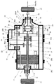
図1は、本発明が適用された電気式4輪駆動車両におけるリアトランスアクスル10の構成を示すスケルトン図である。リアトランスアクスル10は、駆動源としての電動機11と、その電動機11の出力軸12とそれに平行なカウンタ軸13との間に設けられた第1減速ギヤ対14と、カウンタ軸13とそのカウンタ軸13に平行且つ電動機11と同心のデファレンシャルケース15との間に設けられた第2減速ギヤ対16と、デファレンシャルケース15内に設けられた差動機構17を有し、電動機11から第1減速ギヤ対14および第2減速ギヤ対16を介して伝達されたトルクにより一対の後方車軸18を回転駆動する差動歯車装置19とをトランスアクスルケース20(ケースに相当する)内に備えて構成される2軸型の車両用電動式駆動装置である。
FIG. 1 is a skeleton diagram showing a configuration of a
出力軸12の中央部には電動機11のロータ11aが連結され、両端側には一対の軸受21が装着されて、出力軸12は、それら一対の軸受21を介してトランスアクスルケース20により回転可能に支持されている。
The
第1減速ギヤ対14は、小径側のカウンタドライブギヤ22と、大径側のカウンタドリブンギヤ23とから成る。カウンタドライブギヤ22は、出力軸12の一端部の先端側に一体的に固定されている。また、カウンタドリブンギヤ23は、カウンタドライブギヤ22と噛み合う状態でカウンタ軸13の一端側に一体的に固定されている。第1減速ギヤ対14の回転軸には、出力軸12および出力軸12とは平行なるカウンタ軸13が相当するもので、従って、第1減速ギヤ対14の回転軸方向とは、出力軸12又はカウンタ軸13の軸方向を指し、図1では、左右方向が該当する。
The first
カウンタ軸13は、それぞれ同心に設けられた出力軸12やデファレンシャルケース15、およびそれらに固定されたカウンタドライブギヤ22や後述のファイナルドリブンギヤ26(減速ギヤに相当する)よりも車両前方側に設けられている。これにより、カウンタドリブンギヤ23は、トランスアクスルケース20内の最前方側に配置される。このカウンタ軸13の両端部には、一対の軸受24が嵌め着けられている。このカウンタ軸13は、これら一対の軸受24を介してトランスアクスルケース20により回転可能に支持されている。
The
第2減速ギヤ対16は、図1に示すように第1減速ギヤ対14の回転軸方向に変位して配置されるもので、小径側のファイナルドライブギヤ25と、大径側のファイナルドリブンギヤ26とから成る。ファイナルドライブギヤ25は、カウンタ軸13の他端部に一体的に固定されている。また、ファイナルドリブンギヤ26は、カウンタドライブギヤ22とは出力軸12の軸方向に変位して配置され、ファイナルドライブギヤ25と噛み合う状態でデファレンシャルケース15の外周部に嵌め着けられて一体的に固定されている。
As shown in FIG. 1, the second
デファレンシャルケース15の軸方向両端側の外周面には、一対の軸受27が嵌め着けられている。従って、デファレンシャルケース15及びデファレンシャルケース15に一体的に固定されたファイナルドリブンギヤ26は、これら一対の軸受27を介してトランスアクスルケース20により回転可能に支持されている。
A pair of
差動機構17は、一般周知の所謂傘歯車式のものであり、デファレンシャルケース15内においてその回転軸心上で相対向する一対のサイドギヤ28と、それら一対のサイドギヤ28間においてデファレンシャルケース15の回転軸心に直交する状態でそのデファレンシャルケース15に固設されたピニオンシャフト29により回転可能に支持されるとともに、上記一対のサイドギヤ28とそれぞれ噛み合う一対のピニオンギヤ30とを備えている。
The
一対の後方車軸18は、一対のサイドギヤ28に一体的に連結されている。デファレンシャルケース15と差動機構17とを備えて構成される差動歯車装置19は、電動機11から第1減速ギヤ対14および第2減速ギヤ対16を介して伝達されたトルクにより、一対の後方車軸18の回転速度差を許容しつつそれら一対の後方車軸18を回転駆動するものである。なお、一対の後方車軸18の一方は、中空円筒状に形成された出力軸12を挿通して一対の後輪31の車両左側の一方に連結されている。
The pair of
トランスアクスルケース20は、図1に示す如く、後方車軸18の軸線方向において4
分割されて構成される。トランスアクスルケース20の構成要素である区画部材20dは
、筒状で、トランスアクスルケース20内を第1減速ギヤ対14が収容される第1収容部
20Aと第2減速ギヤ対16が収容される第2収容部20Bに区画する区画壁20d1(
図4示)を有する。トランスアクスルケース20は、さらに、区画部材20dの一側(図
1の左側)に固定され、第1収容部20Aを形成する第1側壁20a1(図2示)を有する
筒状の第1分割ケース部20aと、区画部材20dの他側(図1の右側)に固定され、第
2収容部20Bを形成する第2側壁20b1(図1示、図3示及び図5示、側壁に相当す
る)を有する蓋状の第2分割ケース部20bと、主として電動機11を収容する蓋状の第
3分割ケース部20cとを備える。トランスアクスルケース20の構成要素である第1分
割ケース部20aと、第2分割ケース部20bと、第3分割ケース部20cと、区画部材
20dは、図示しないボルトによって相互に締着されることにより油密に図1に示す如く
構成されている。これらの分割ケース部20a,20b,20c、区画部材20dは、鋳
造軽合金例えばアルミダイカスト等により形成されている。区画部材20dには、前述し
た一対の軸受21の片方及び前述した一対の軸受27の片方が支持されている。
As shown in FIG. 1, the
Divided and configured. The
4). The
そして、カウンタドリブンギヤ23とファイナルドリブンギヤ26は、その回転によりトランスアクスルケース20の底部に貯溜された潤滑油を掻き上げて各潤滑部位に供給するようになっている。すなわち、本実施形態のリアトランスアクスル10には、トランスアクスルケース20内の底部に貯溜される潤滑油を掻き上げて各潤滑部位に供給する掻き上げ潤滑方式が採用されている。上記潤滑部位には、例えば第1減速ギヤ対14および第2減速ギヤ対16の噛合部、差動機構17のギヤ噛合部や回転摺動部、および各軸受21,24,27などが相当する。
The counter driven
ここで、トランスアクスルケース20には、車速Vが上がるにつれて上昇するカウンタドリブンギヤ23による潤滑油の攪拌抵抗を低減することを目的として、トランスアクスルケース20内の底部に貯溜される潤滑油の油面位置を下げるために、掻き上げられる潤滑油の一部を貯溜するための第1キャッチタンク32が設けられている。この第1キャッチタンク32は、図2及び図3に示すように、トランスアクスルケース20の底部の油面のレベルH1よりも高い位置で潤滑油が貯溜できるように、分割ケース部20a、20b、20c及び区画部材20dに亘って設けられている。油面のレベルH1は、停車時におけるトランスアクスルケース20の底部に貯溜される潤滑油の高さである。
Here, in the
トランスアクスルケース20の上方をスペアタイヤあるいは車載蓄電池の搭載スペースとして確保するために、本実施形態では、第1キャッチタンク32は、第1減速ギヤ対14及び前記第2減速ギヤ対16とは上下方向にオーバーラップを避ける位置一例としてトランスアクスルケース20の最後方側(カウンタ軸13を含む第1減速ギヤ対14および第2減速ギヤ対16よりも車両後方側、即ち、図1では下方、図2及び図4では左方、図3及び図5では右方)に配置されている。即ち、第1キャッチタンク32を配置する位置として、第1減速ギヤ対14及び前記第2減速ギヤ対16とは上下方向にオーバーラップを避ける位置とは、たとえ第1減速ギヤ対14及び前記第2減速ギヤ対16の上方に架かるとしても、少なくとも、第1減速ギヤ対14及び前記第2減速ギヤ対16の高さ方向の最上方位置よりも上方に位置する部分には架らない区域を指す。第1減速ギヤ対14のカウンタドリブンギヤ23により掻き上げられる潤滑油の多くが図2中の矢印Aのように上方且つ後方へ飛ばされるようになっているため、第1キャッチタンク32は、掻き上げられる潤滑油を効率的に収容可能な位置すなわちトランスアクスルケース20の最後方側に配設されている。
In order to secure the space above the
これにより、第2減速ギヤ対16のファイナルドリブンギヤ26に比較して回転速度が速くて潤滑油の掻き上げ能力に優れる(掻き上げ量が多い)カウンタドリブンギヤ23の潤滑油の掻き上げ作動が、円滑に行われるようになっている。なお、第1キャッチタンク32に貯溜された潤滑油は、その第1キャッチタンク32に設けられた図示しない潤滑油供給口から他の潤滑部位へ供給されるか、所定量以上溜まることで第1キャッチタンク32からオーバーフローされるか、あるいはトランスアクスルケース20の底部の油面位置が低下することで潤滑油に浸漬されなくなった軸受やオイルシール等の潤滑必要箇所に第1キャッチタンク32の底部に設けられた図示しない排出口からの自然流出油が供給されることによって、トランスアクスルケース20内の底部に戻されるようになっている。
Thereby, compared with the final driven
トランスアクスルケース20の第1分割ケース部20aの内部には、第1減速ギヤ対14のカウンタドリブンギヤ23により掻き上げられる潤滑油を図2中の矢印Aで示すようにキャッチタンク32へ導く第1油路33が設けられている。一方、トランスアクスルケース20の第2分割ケース部20bの内部には、第2減速ギヤ対16のファイナルドリブンギヤ26に掻き上げられる潤滑油を図3中の矢印Bで示すように第2キャッチタンク35へ導く第2油路34(油路に相当する)が設けられている。第2油路34は、図1に示すように、第1油路33とは、第1減速ギヤ対14のカウンタドリブンギヤ23の回転軸なるカウンタ軸13の軸方向に変位(即ち、図1において右方)して配置されている。なお、第2油路34の配置位置は、第1油路33とは、第1減速ギヤ対14のカウンタドライブギヤ22の回転軸なる出力軸12の軸方向に変位した位置(即ち、図1において右方)でもある。つまり、第2油路34は、第1油路33とは第1減速ギヤ対14の回転軸方向に変位して配置されている。
Inside the first
図2に示す如く、第1油路33は、第1分割ケース部20aの第1側壁20a1に立設された第1油路壁20a2の外周面上に形成される。第1油路33は、第1油路壁20a2の外周面と第1分割ケース部20aの外周壁20a3にて径方向の区画をして形成され、その第1油路33はカウンタドリブンギヤ23により掻き上げられる潤滑油を第1キャッチタンク32へ導く。
As shown in FIG. 2, the
図3に示す如く、第2油路34は、第2分割ケース部20bの第2側壁20b1に立設された第2油路壁20b2の外周面上に形成される。第2油路34は、第2油路壁20b2の外周面と第2分割ケース部20bの外周壁20b3にて径方向の区画をして形成され、その第2油路34はファイナルドリブンギヤ26により掻き上げられる潤滑油を第2キャッチタンク35へ導く。第2キャッチタンク35は、掻き上げられる潤滑油を貯溜してトランスアクスルケース20内の底部に貯溜される潤滑油の油面位置を下げるために、図3乃至図5に示すように、第1キャッチタンク32と同様にトランスアクスルケース20の底部の油面のレベルH1よりも高い位置に設けられている。
As shown in FIG. 3, the
第2キャッチタンク35は、第2油路壁20b2の外周面と区画部材20dの区画壁20d1に立設されたタンク壁20d2(図4示)の外周面と、第2分割ケース部20bの外周壁20b3と区画部材20dの外周壁20d3(図4示)にて径方向の区画をして形成されている。第2キャッチタンク35は、第2分割ケース部20bの第2側壁20b1と区画部材20dの区画壁20d1にての軸方向の区画がされて形成される。第2キャッチタンク35は、その底部に潤滑油を排出する排出孔35aを有する。第2キャッチタンク35に導かれた潤滑油は、排出孔35aから自然流出し、トランスアクスルケース20内の底部に戻されるようになっている。
The
第2キャッチタンク35は、図1に示す如く、ファイナルドライブギヤ25の外周側でかつカウンタドリブンギヤ23の回転軸方向でカウンタドリブンギヤ23の収容スペースの投影面積内である位置に設けられている。第2キャッチタンク35は、この様に、第1減速ギヤ対14及び第2減速ギヤ対16を備えた減速機のユニットのデッドスペースに設けることができるため、減速機のユニット体格を大きくすることなく、第1キャッチタンク32を含めたキャッチタンク全体の容量を増やすことができる。
As shown in FIG. 1, the
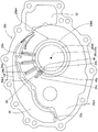
区画部材20dの区画壁20d1には、図4に示す如く、第1油路33と第2油路34とを連通する連通部として窓36が設けられている。第2分割ケース部20bは、図3に示す如く、第2油路34に掻き上げられた潤滑油を窓36へ案内可能な堰部37を第2油路壁20b2の外周面に有する。この堰部37は、第2分割ケース部20bを鋳造する際に鋳型から抜き易くするために通常設けられる押出ピン座を利用したものである。堰部37は、第2油路34の窓36に対応した位置に近接した下流側に設けられて、図3に示す如く、第2油路34に掻き上げられた潤滑油の流れ(矢印Bにて示す)の一部を、窓36に向けて向きを変え、第1油路33と合流するように、矢印Cの如く導く作用をする。図4に示す如く、区画部材20dの区画壁20d1に立設された案内壁38は、タンク壁20d2と外周壁20d3を繋いで、矢印Cにて導かれた潤滑油を窓36へと案内する。
As shown in FIG. 4, the
区画部材20dに設けられた窓36を介して、掻き上げられた潤滑油を第2キャッチタンク35へ導く第2油路34が、掻き上げられた潤滑油を第1キャッチタンク32へ導く第1油路33に連通する。これにより、それぞれ掻き上げられた潤滑油が導かれて貯められる第1キャッチタンク32と第2キャッチタンク35との2つのキャッチタンク32、35のうち第2キャッチタンク35が先に潤滑油の貯留量が満杯となり潤滑油を収容しきれない状態になっても、その収容しきれない潤滑油は、窓36にて未だ貯蔵量に余裕のある第1キャッチタンク32へと、図3示の矢印Cに示す如く導くことができるので、潤滑油の掻き上げ効率を向上できる。なお、第1キャッチタンク32が先に潤滑油の貯留量が満杯となり潤滑油を収容しきれない状態になっても、その収容しきれない潤滑油は、第1油路33から窓36を介して、第2油路34へと合流し、未だ貯蔵量に余裕のある第2キャッチタンク35へと導くことができるので、潤滑油の掻き上げ効率を向上できる。
A
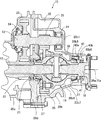
図5に示す如く、第2分割ケース部20bの第2側壁20b1の内面側における第2油路34の背面側即ち第2油路壁20b2の下方側付近の位置から、第2側壁20b1におけるファイナルドリブンギヤ26の回転軸線26a側即ちデファレンシャルケース15の回転軸線15a側である内周部20b4に向けて延在したリブ39が設けられている。リブ39の端縁39aに対向して設けられて、リブ39にて捕捉された潤滑油が導入されるとともに潤滑油供給対象に連通する溝部40が、第2側壁20b1に設けられている。潤滑油供給対象は、ファイナルドリブンギヤ26を第2分割ケース部20bに支承する軸受27と第2分割ケース部20b内を外部から遮断するオイルシール41であり、第2側壁20b1のファイナルドリブンギヤ26の回転軸線26a側に設けられている。この様に、第2分割ケース部20bには、内部に形成される第2側壁20b1と回転軸線26aとの間に潤滑油供給対象である軸受27とオイルシール41が設けられている。第2側壁20b1に径方向に延在して形成されたリブ39は、掻き上げられた潤滑油を内径方向へと導く。
As shown in FIG. 5, the final of the second side wall 20b1 from the position on the inner surface side of the second side wall 20b1 of the second divided
ファイナルドリブンギヤ26の回転方向において、リブ39よりも手前側に補助リブ39bが少なくとも1つ、図5に示す例では3つが、リブ39と放射状に並設されている。第2側壁20b1は、図6に示す如く、ファイナルドリブンギヤ26から離れるにつれて、ファイナルドリブンギヤ26の回転軸線26aに近づくテーパ部20b7を有するテーパ形状に形成されている。デファレンシャルケース15の一部分は、第2側壁20b1のテーパ部20b7に対向して設けられ、両者の間にテーパ状の隙間20b8(図6示)を形成されている。
In the rotational direction of the final driven
溝部40は、図5及び図6に示す如く、第2分割ケース部20bに設けられた軸受27の軸受穴20b5の内周面に凹設された溝部40aと軸受27とオイルシール41との間に形成された段差壁20b6に凹設された溝部40bを有する。軸受27の軸受穴20b5の内周面に凹設された溝部40aの部分は、リブ39より幅が広く形成されている、溝部40は、リブ39の幅方向の略中央に設けられている。溝部40は、潤滑油を潤滑油供給対象である軸受27、オイルシール41に導き、その潤滑油は、軸受27、オイルシール41を潤滑後、トランスアクスルケース20内の底部に戻されるようになっている。溝部40は、リブ39の幅方向の略中央に設けられていることにより、減速ギヤ26が例えば車両の後進時の如く、逆回転する場合にも、前進時と同様に、潤滑油をリブ39から溝部40に導入することができる。
As shown in FIGS. 5 and 6, the
第2分割ケース部20bには、リブ39が設けられていることにより、ファイナルドリブンギヤ26にて掻き上げられた潤滑油の内、掻き上げ高さが低く第2油路34に到達できなかった潤滑油は、図5示の矢印Dに示す如く、第2油路34の背面側即ち第2油路壁20b2の下方付近を通ることとなる。この矢印Dにて示される潤滑油の流れは、リブ39にて回転を規制され、リブ39に沿って回転軸線26a側に流れ、軸受27に外周側方から供給されて潤滑するとともに軸受穴20b5の内周部に形成された溝部40aに流入する。また、溝部40aに流入した潤滑油は、段差壁20b6に形成された溝部40bを通って、潤滑油供給対象の軸受27の背側(図6において右側)から軸受27に供給されて潤滑し、また潤滑油供給対象のオイルシール41に供給されて潤滑する。
The second divided
また、ファイナルドリブンギヤ26の回転方向において、リブ39よりも手前側に補助リブ39bを設けることにより、ファイナルドリブンギヤ26にて掻き上げられた潤滑油の内、掻き上げ高さが低く第2油路34に到達できなかった潤滑油を補助リブ39bにても捕捉できる。ファイナルドリブンギヤ26にて掻き上げられ、第2側壁20b1のテーパ部20b7に向かって回転軸線26a方向に飛散された潤滑油は、テーパ部20b7とデファレンシャルケース15の外周面との間に形成されたテーパ状の隙間20b8に流入する。補助リブ39bによって回転規制された潤滑油の一部は、補助リブ39b及びテーパ部20b7の壁面に沿って回転軸線26a側に流れて軸受27に外周側方から供給されて潤滑する。補助リブ39bを乗り越えてリブ39に到達した潤滑油と、最後の補助リブ39bとリブ39の間に流入した潤滑油は、リブ39にて回転を規制されリブ39に沿って回転軸線26a側に流れ、軸受27に供給されるとともに軸受穴20b5の内周部に形成された溝部40aに流入する。また、溝部40aに流入した潤滑油は、段差壁20b6に形成された溝部40bを通って、潤滑油供給対象の軸受27の背側(図6において右側)から軸受27に供給されて潤滑し、また潤滑油供給対象のオイルシール41に供給されて潤滑する。この様に、ファイナルドリブンギヤ26にて掻き上げられた潤滑油の一部は、第2キャッチタンク32及び第1キャッチタンク32を経由することなく、直接に潤滑油供給対象の軸受27、オイルシール41に供給されることにより、迅速に潤滑できる。又、リブ39及び溝部40により、ファイナルドリブンギヤ26にて掻き上げられた潤滑油が、滑油供給対象の軸受27、オイルシール41に潤滑油を供給されるため、特別に油路を形成する必要がない。
Further, in the rotation direction of the final driven
図2及び図3に示すように、第1減速ギヤ対14のカウンタドリブンギヤ23と第2減速ギヤ対16のファイナルドリブンギヤ26とは、車両が停車した状態では、その略下半部が少なくともトランスアクスルケース20の底部に貯溜される潤滑油に浸漬される高さ位置に配設される。なお、図2及び図3中の2点鎖線にて示すレベルH1は、停車時におけるトランスアクスルケース20の底部に貯溜される潤滑油の高さを示す。又、電動機11のロータ11aも、停車時にはその略下半部が少なくともトランスアクスルケース20の底部に貯溜される潤滑油に浸漬される高さ位置に配設される。
As shown in FIGS. 2 and 3, the counter driven
車両の走行が始まり、車両速度の上昇に伴い、トランスアクスルケース20の底部に貯溜される潤滑油は掻き上げられ量が増加して潤滑油の高さはレベルH1から徐々に下がり始め、車両速度が略時速50キロメートルの状態では、トランスアクスルケース20の底部に貯溜される潤滑油の高さは、図2及び図3中の2点鎖線にて示すレベルH2となり、第1減速ギヤ対14のカウンタドリブンギヤ23はその最下部も殆ど潤滑油に浸漬されない状態であるが、一方、第2減速ギヤ対16のファイナルドリブンギヤ26の下端は潤滑油に浸漬された状態が保持される。
As the vehicle starts to travel and the vehicle speed increases, the amount of lubricating oil stored at the bottom of the
従って、車両速度が略時速50キロメートルの状態に至り、潤滑油の掻き上げ能力がファイナルドリブンギヤ26よりも優れたカウンタドリブンギヤ23によるトランスアクスルケース20の底部からの潤滑油の掻き上げが難しくなっても、ファイナルドリブンギヤ26による潤滑油を掻き上げ可能な状態は、維持される。構造上、ファイナルドリブンギヤ26の回転はカウンタドリブンギヤ23よりも遅いが、車両速度が略時速50キロメートルでは、ファイナルドリブンギヤ26の回転も上昇しているため、トランスアクスルケース20の底部からの潤滑油の掻き上げはファイナルドリブンギヤ26のみにても行うことが可能である。
Accordingly, even when the vehicle speed reaches approximately 50 km / h and the
上述のように、本実施形態のリアトランスアクスル(減速機の潤滑構造)10によれば、内部に形成される側壁20b1と回転軸線26aとの間に潤滑油供給対象27,41が設けられるケース20と、ケース20内に設けられ、駆動源11の出力軸12と連結され、回転軸線26a回りで回転する減速ギヤ26と、ケース20の底部に貯溜され減速ギヤ26により掻き上げられて潤滑油の一部を貯溜するキャッチタンク35と、側壁20b1に設けられ、減速ギヤ26により掻き上げられた潤滑油をキャッチタンク35へ導く油路34と、側壁20b1に径方向に延在して形成され、掻き上げられた潤滑油を内径方向へと導くリブ39と、側壁20b1のリブ39の端縁39aに設けられて、リブ39にて捕捉された潤滑油が導入されるとともに潤滑油供給対象27,41に連通する溝部40を備える。これにより、減速ギヤ26により掻き上げられた潤滑油が、リブ39によりキャッチタンク35を経由することなく、潤滑油供給対象27,41に迅速に供給される。又、減速ギヤ26により掻き上げられても、従来はキャッチタンク35へ到達できずにケース20底部へ棄てられていた潤滑油が、潤滑油供給対象27,41に供給できるため、潤滑油の有効活用ができる。
As described above, according to the rear transaxle (reduction gear lubrication structure) 10 of the present embodiment, the lubricant supply targets 27 and 41 are provided between the side wall 20b1 formed inside and the rotation axis 26a. 20, a
上述のように、本実施形態のリアトランスアクスル(減速機の潤滑構造)10によれば、減速ギヤ26の回転方向において、リブ39より手前に少なくとも1つ放射状に補助リブ39bが形成され、側壁20b1は、減速ギヤ26から離れるにつれて回転軸線26aに近づくテーパ形状に形成される。これにより、減速ギヤ26にて掻き上げられた潤滑油の内、掻き上げ高さが低く油路34に到達できなかった潤滑油を補助リブ39bにても回転が規制されて捕捉できる。補助リブ39bにて捕捉された潤滑油は、補助リブ39b及び側壁20b1のテーパ形状の壁面に沿って回転軸線26a側に流れ、また補助リブ39bを乗り越えてリブ39に到達した潤滑油は、リブ39にて回転が規制されリブ39に沿って回転軸線26a側に流れて、潤滑油供給対象27、41に供給されて潤滑する。従って、減速ギヤ26にて掻き上げられた潤滑油の内、掻き上げ高さが低く油路34に到達できなかった潤滑油の捕捉を補助リブ39bにより向上して、潤滑油を潤滑油供給対象27、41に供給できる。
As described above, according to the rear transaxle (reduction gear lubrication structure) 10 of the present embodiment, at least one
上述のように、本実施形態のリアトランスアクスル(減速機の潤滑構造)10によれば、潤滑油供給対象は、減速ギヤ26をケース20に支承する軸受27及び軸受27と並設されケース20内を外部から遮断するオイルシール41であり、溝部40はケース20に設けられた軸受穴20b5の内周面と軸受27とオイルシール41との間に形成された段差壁20b6に凹設され、溝部40の軸受穴20b5に形成された部分は、リブ39より幅が広く形成され、溝部40は、リブ39の幅方向の略中央に設けられる。これにより、減速ギヤ26が例えば車両の後進時の如く、逆回転する場合にも、前進時と同様に、潤滑油をリブ39から溝部40に導入することができる。溝部40により、減速ギヤ26をケース20に支承する軸受27及び軸受27と並設されケース20内を外部から遮断するオイルシール41に潤滑油を供給できるため、特別に油路を形成する必要がない。
As described above, according to the rear transaxle (reduction gear lubrication structure) 10 of the present embodiment, the lubricating oil supply target is provided side by side with the
上述のように、本実施形態のリアトランスアクスル(減速機の潤滑構造)10によれば、減速ギヤ26は、1対の車軸18を回転駆動する差動機構17を内部に有するデファレンシャルケース15に固定される。これにより、デファレンシャルケース15を有する車両に適用できる。
As described above, according to the rear transaxle (reduction gear lubrication structure) 10 of the present embodiment, the
また、複数の実施の形態が存在する場合、特に記載がある場合を除き、各々の実施の形態の特徴部分を適宜組合せることが可能であることは、明らかである。 In addition, when there are a plurality of embodiments, it is obvious that the features of each embodiment can be appropriately combined unless otherwise specified.
11・・・電動機(駆動源)、15・・・デファレンシャルケース、17・・・差動機構、18・・・車軸、20・・・トランスアクスルケース(ケース)、20b1・・・第2側壁(側壁)、20b5・・・軸受穴、20b6・・・段差壁、26・・・ファイナルドリブンギヤ(減速ギヤ)、26a・・・回転軸線、27・・・軸受(潤滑油供給対象)、34・・・第2油路(油路)、35・・・第2キャッチタンク(キャッチタンク)、39・・・リブ、39a・・・リブの端縁、39b・・・補助リブ、40・・・溝部、41・・オイルシール(潤滑油供給対象)
DESCRIPTION OF
Claims (4)
前記ケース内に設けられ、駆動源の出力軸と連結され、前記回転軸線回りで回転する減速ギヤと、
前記ケースの底部に貯溜され前記減速ギヤにより掻き上げられて潤滑油の一部を貯溜するキャッチタンクと、
前記側壁に設けられ、前記減速ギヤにより掻き上げられた潤滑油を前記キャッチタンクへ導く油路と、
前記油路の背面側で前記側壁に径方向に延在して形成され、前記減速ギヤにより掻き上げられた潤滑油の内、掻き上げ高さが低く前記油路に到達できなかった潤滑油を内径方向へと導くリブと、
前記側壁の前記リブの端縁に設けられ、前記リブにて捕捉された前記潤滑油が導入されて前記キャッチタンクを経由することなく前記潤滑油供給対象に供給する溝部と、
前記減速ギヤの回転方向において、前記リブより手前に少なくとも1つ放射状に形成された補助リブと、を備え、
前記側壁は、前記減速ギヤから離れるにつれて前記回転軸線に近づくテーパ形状に形成された減速機の潤滑構造。 A case in which a lubricant supply target is provided between a side wall formed inside and a rotation axis;
A reduction gear provided in the case, connected to the output shaft of the drive source, and rotating around the rotation axis;
A catch tank that is stored at the bottom of the case and is scraped up by the reduction gear to store a part of the lubricating oil;
An oil passage that is provided on the side wall and guides the lubricating oil scraped up by the reduction gear to the catch tank;
Of the lubricating oil that is formed to extend in the radial direction on the side wall on the back side of the oil passage and is scraped up by the reduction gear, the lubricating oil that has a low scraping height and cannot reach the oil passage. A rib leading to the inner diameter direction;
Provided on an end edge of the ribs of the sidewall, the groove is supplied to the lubricating oil supply target without passing through the catch tank is introduced the lubricant oil capture by the rib,
An auxiliary rib formed radially in front of the rib in the rotational direction of the reduction gear, and
The lubrication structure of a speed reducer, wherein the side wall is formed in a tapered shape that approaches the rotation axis as the distance from the speed reduction gear increases .
Priority Applications (4)
| Application Number | Priority Date | Filing Date | Title |
|---|---|---|---|
| JP2014221108A JP6076314B2 (en) | 2014-10-30 | 2014-10-30 | Reducer lubrication structure |
| US14/926,623 US9856971B2 (en) | 2014-10-30 | 2015-10-29 | Lubricating structure for speed reducer |
| DE102015013973.8A DE102015013973A1 (en) | 2014-10-30 | 2015-10-29 | Lubricating structure for a speed reducer |
| CN201510727270.7A CN105570442B (en) | 2014-10-30 | 2015-10-30 | The lubrication system of retarder |
Applications Claiming Priority (1)
| Application Number | Priority Date | Filing Date | Title |
|---|---|---|---|
| JP2014221108A JP6076314B2 (en) | 2014-10-30 | 2014-10-30 | Reducer lubrication structure |
Publications (2)
| Publication Number | Publication Date |
|---|---|
| JP2016089861A JP2016089861A (en) | 2016-05-23 |
| JP6076314B2 true JP6076314B2 (en) | 2017-02-08 |
Family
ID=55753357
Family Applications (1)
| Application Number | Title | Priority Date | Filing Date |
|---|---|---|---|
| JP2014221108A Active JP6076314B2 (en) | 2014-10-30 | 2014-10-30 | Reducer lubrication structure |
Country Status (4)
| Country | Link |
|---|---|
| US (1) | US9856971B2 (en) |
| JP (1) | JP6076314B2 (en) |
| CN (1) | CN105570442B (en) |
| DE (1) | DE102015013973A1 (en) |
Families Citing this family (34)
| Publication number | Priority date | Publication date | Assignee | Title |
|---|---|---|---|---|
| JP6129139B2 (en) * | 2014-10-30 | 2017-05-17 | アイシン精機株式会社 | Reducer lubrication structure |
| JP6076314B2 (en) * | 2014-10-30 | 2017-02-08 | アイシン精機株式会社 | Reducer lubrication structure |
| JP6129150B2 (en) * | 2014-12-24 | 2017-05-17 | アイシン精機株式会社 | Lubricating structure for vehicle drive device |
| JP6086897B2 (en) * | 2014-12-24 | 2017-03-01 | アイシン精機株式会社 | Lubricating structure for vehicle drive device |
| US10208848B2 (en) * | 2015-07-29 | 2019-02-19 | GM Global Technology Operations LLC | Gear baffle |
| JP6419663B2 (en) * | 2015-08-26 | 2018-11-07 | 株式会社丸山製作所 | Reciprocating pump device |
| JP6564812B2 (en) * | 2017-05-29 | 2019-08-21 | 本田技研工業株式会社 | Transmission lubrication structure |
| CN109681619B (en) * | 2017-10-19 | 2022-02-08 | 上海汽车集团股份有限公司 | Oil distribution system and oil distribution disc assembly of gearbox |
| US10859152B2 (en) * | 2017-11-13 | 2020-12-08 | Zhejiang Xin Precision Mach Co., Ltd. | Pure electric vehicle transmission with novel lubrication structure |
| WO2019098166A1 (en) * | 2017-11-14 | 2019-05-23 | 日本電産株式会社 | Motor unit |
| CN108194625A (en) * | 2018-01-09 | 2018-06-22 | 清华大学 | A kind of method for arranging of drive axle differential case body oil duct and drive axle differential mechanism |
| US11242924B2 (en) * | 2018-03-02 | 2022-02-08 | Dana Heavy Vehicle Systems Group, Llc | Lubricant regulating system and an axle assembly made therewith |
| JP7204289B2 (en) * | 2018-04-18 | 2023-01-16 | 住友重機械工業株式会社 | gearbox |
| CN110715044B (en) * | 2018-07-13 | 2022-11-01 | 富田电机股份有限公司 | Oil circuit system of power assembly of electric locomotive |
| CN109084011B (en) * | 2018-09-25 | 2024-01-02 | 陕西法士特齿轮有限责任公司 | Transmission lubrication system |
| US10787073B2 (en) * | 2018-12-11 | 2020-09-29 | Ford Global Technologies, Llc | Electric drive unit for vehicle with clockable gearbox |
| DE102019102078B3 (en) | 2019-01-28 | 2020-06-04 | Gkn Automotive Limited | Gear arrangement |
| DE102019201586A1 (en) * | 2019-02-07 | 2020-08-13 | Volkswagen Aktiengesellschaft | Oil container for cooling and / or lubricating bearings of a drive train of a vehicle, in particular a motor vehicle |
| DE102019201585A1 (en) * | 2019-02-07 | 2020-09-24 | Volkswagen Aktiengesellschaft | Drive train for a vehicle, in particular for a motor vehicle |
| JP6702469B1 (en) * | 2019-02-26 | 2020-06-03 | スズキ株式会社 | Vehicle drive |
| JP6702468B1 (en) * | 2019-02-26 | 2020-06-03 | スズキ株式会社 | Vehicle drive |
| JP7200831B2 (en) * | 2019-06-12 | 2023-01-10 | トヨタ自動車株式会社 | vehicle power transmission |
| JP7281639B2 (en) * | 2019-06-28 | 2023-05-26 | ニデック株式会社 | motor unit |
| JP7310400B2 (en) * | 2019-07-22 | 2023-07-19 | スズキ株式会社 | Transmission lubrication structure |
| US11280396B2 (en) * | 2019-11-13 | 2022-03-22 | Rolls-Royce Corporation | Fire resistant gearbox housing |
| CN110905990B (en) * | 2019-11-26 | 2021-04-27 | 东风格特拉克汽车变速箱有限公司 | Differential mechanism for improving bearing lubrication of differential mechanism and lubrication method |
| KR20210155641A (en) * | 2020-06-16 | 2021-12-23 | 현대자동차주식회사 | Motor apparatus having circulation structure of oil |
| KR20220009210A (en) | 2020-07-15 | 2022-01-24 | 현대자동차주식회사 | Motor system having circulation structure of oil |
| CN112483636B (en) * | 2020-10-27 | 2022-06-14 | 中国船舶重工集团公司第七0三研究所 | Large-lubricating-oil-flow central transmission shell for gas turbine |
| CN112483635B (en) * | 2020-10-27 | 2022-06-14 | 中国船舶重工集团公司第七0三研究所 | Large-lubricating-oil-flow central transmission mechanism for gas turbine |
| DE102022202448A1 (en) | 2022-03-11 | 2023-09-14 | Zf Friedrichshafen Ag | Transmission device for a motor vehicle and vehicle with the transmission device |
| US11773962B1 (en) * | 2022-03-28 | 2023-10-03 | Borgwarner Inc. | Electric drive unit with integrated, variable flow, low-pressure oil cooling system |
| JP7445697B2 (en) * | 2022-03-30 | 2024-03-07 | 本田技研工業株式会社 | Lubrication structure of vehicle power transmission device |
| CN115263487B (en) * | 2022-09-02 | 2024-04-16 | 中国重汽集团济南动力有限公司 | Oil pumping device without additional power |
Family Cites Families (36)
| Publication number | Priority date | Publication date | Assignee | Title |
|---|---|---|---|---|
| US2049234A (en) * | 1935-04-03 | 1936-07-28 | Reo Motor Car Co | Transmission mechanism |
| US3529698A (en) * | 1967-05-05 | 1970-09-22 | Gen Electric | Self-operating lubrication system for gear drive units |
| US4470324A (en) * | 1981-10-19 | 1984-09-11 | Carol A. MacKay | Gear case |
| US4648485A (en) * | 1985-10-04 | 1987-03-10 | United Technologies Corporation | Radial scoop construction |
| DE4414164A1 (en) * | 1994-04-22 | 1995-10-26 | Zahnradfabrik Friedrichshafen | Gear housing |
| EP1229270A3 (en) * | 1995-12-21 | 2003-08-13 | Aisin Aw Co., Ltd. | Drive apparatus for electric vehicle |
| JPH1148806A (en) * | 1997-08-08 | 1999-02-23 | Jatco Corp | Oil lubrication structure of differential mechanism |
| JP2003312282A (en) * | 2002-04-19 | 2003-11-06 | Fuji Heavy Ind Ltd | Vehicle drive |
| JP2004180477A (en) * | 2002-11-29 | 2004-06-24 | Honda Motor Co Ltd | Cooling structure of motor in front and rear wheel drive vehicle |
| JP4409929B2 (en) * | 2003-12-19 | 2010-02-03 | 本田技研工業株式会社 | Lubrication structure of differential equipment |
| JP4563069B2 (en) * | 2004-04-20 | 2010-10-13 | 本田技研工業株式会社 | Parallel shaft automatic transmission |
| US7753173B2 (en) * | 2004-07-26 | 2010-07-13 | Magna Drivetrain Ag & Co Kg | Power divider for motor vehicles and lubrication thereof |
| JP4662346B2 (en) * | 2005-04-12 | 2011-03-30 | トヨタ自動車株式会社 | Lubricating device in vehicle power transmission device |
| JP4771517B2 (en) * | 2005-04-26 | 2011-09-14 | トヨタ自動車株式会社 | Lubricating device in vehicle power transmission device |
| JP2008014406A (en) * | 2006-07-06 | 2008-01-24 | Jatco Ltd | Automatic transmission |
| JP4898653B2 (en) * | 2007-12-27 | 2012-03-21 | アイシン・エィ・ダブリュ株式会社 | Power transmission device for vehicle |
| JP4831078B2 (en) * | 2008-01-16 | 2011-12-07 | トヨタ自動車株式会社 | Power transmission device |
| JP4743241B2 (en) * | 2008-08-29 | 2011-08-10 | トヨタ自動車株式会社 | Power transmission device |
| DE102010004222A1 (en) * | 2009-01-19 | 2010-07-29 | Magna Powertrain Ag & Co Kg | Gearbox with lubrication device |
| JP2011007208A (en) * | 2009-06-23 | 2011-01-13 | Aisin Ai Co Ltd | Transmission |
| JP5136655B2 (en) * | 2010-02-04 | 2013-02-06 | トヨタ自動車株式会社 | Lubricating oil supply device |
| US8371978B2 (en) * | 2010-03-31 | 2013-02-12 | Aisin Aw Co., Ltd. | Vehicle transmission |
| US8746405B2 (en) * | 2010-09-23 | 2014-06-10 | Ford Global Technologies, Llc | Variable lubricant level in a differential sump |
| JP5760215B2 (en) * | 2011-01-24 | 2015-08-05 | 株式会社 神崎高級工機製作所 | Axle drive device for work vehicle |
| JP5857413B2 (en) | 2011-02-22 | 2016-02-10 | トヨタ自動車株式会社 | Drive device |
| JP2012189176A (en) * | 2011-03-11 | 2012-10-04 | Showa Corp | Reduction gear and differential device with motor |
| CN103477124B (en) * | 2011-04-20 | 2016-11-23 | 丰田自动车株式会社 | The oil feeding device of power transmission |
| JP2013119918A (en) * | 2011-12-08 | 2013-06-17 | Aisin Seiki Co Ltd | Power transmission device |
| JP5514246B2 (en) * | 2012-03-16 | 2014-06-04 | 本田技研工業株式会社 | Final reduction gear |
| JP5738240B2 (en) * | 2012-07-24 | 2015-06-17 | アイシン精機株式会社 | Reducer lubrication structure |
| JP6076314B2 (en) * | 2014-10-30 | 2017-02-08 | アイシン精機株式会社 | Reducer lubrication structure |
| JP6129139B2 (en) * | 2014-10-30 | 2017-05-17 | アイシン精機株式会社 | Reducer lubrication structure |
| JP6138106B2 (en) * | 2014-11-27 | 2017-05-31 | アイシン精機株式会社 | Reducer lubrication structure |
| JP6129150B2 (en) * | 2014-12-24 | 2017-05-17 | アイシン精機株式会社 | Lubricating structure for vehicle drive device |
| JP6086897B2 (en) * | 2014-12-24 | 2017-03-01 | アイシン精機株式会社 | Lubricating structure for vehicle drive device |
| US9772027B2 (en) * | 2015-10-08 | 2017-09-26 | GM Global Technology Operations LLC | Variable baffle that reduces oil at the gear mesh |
-
2014
- 2014-10-30 JP JP2014221108A patent/JP6076314B2/en active Active
-
2015
- 2015-10-29 US US14/926,623 patent/US9856971B2/en active Active
- 2015-10-29 DE DE102015013973.8A patent/DE102015013973A1/en active Pending
- 2015-10-30 CN CN201510727270.7A patent/CN105570442B/en active Active
Also Published As
| Publication number | Publication date |
|---|---|
| US20160123455A1 (en) | 2016-05-05 |
| JP2016089861A (en) | 2016-05-23 |
| DE102015013973A1 (en) | 2016-05-04 |
| US9856971B2 (en) | 2018-01-02 |
| CN105570442B (en) | 2019-08-30 |
| CN105570442A (en) | 2016-05-11 |
Similar Documents
| Publication | Publication Date | Title |
|---|---|---|
| JP6076314B2 (en) | Reducer lubrication structure | |
| JP6129139B2 (en) | Reducer lubrication structure | |
| JP6086897B2 (en) | Lubricating structure for vehicle drive device | |
| JP5738240B2 (en) | Reducer lubrication structure | |
| JP6138106B2 (en) | Reducer lubrication structure | |
| JP4867491B2 (en) | Driving device and automobile equipped with the same | |
| JP6129150B2 (en) | Lubricating structure for vehicle drive device | |
| JP5966563B2 (en) | Lubrication structure of power transmission device | |
| JP2009168150A (en) | Power transmission device | |
| JP6923753B2 (en) | Vehicle power transmission device | |
| JP2007032797A (en) | Driving device and automobile loading the same | |
| JP2010223376A (en) | Vehicular electric drive unit | |
| JP2015132315A (en) | Oil feed structure of motor drive unit | |
| JP2011196530A (en) | Lubricating oil circulation structure for transmission | |
| JP4662346B2 (en) | Lubricating device in vehicle power transmission device | |
| JP7257228B2 (en) | axle device | |
| JP5462033B2 (en) | Transmission oil supply device | |
| JP5857413B2 (en) | Drive device | |
| WO2020129364A1 (en) | Gear case structure | |
| JP2014020450A (en) | Speed reducer | |
| JP2018003869A (en) | Lubricant circulation device | |
| JP2013096541A (en) | Lubrication mechanism for vehicular drive device | |
| JP2017122487A (en) | Lubrication structure of differential device | |
| JP2016079997A (en) | transmission |
Legal Events
| Date | Code | Title | Description |
|---|---|---|---|
| A977 | Report on retrieval |
Free format text: JAPANESE INTERMEDIATE CODE: A971007 Effective date: 20160829 |
|
| A131 | Notification of reasons for refusal |
Free format text: JAPANESE INTERMEDIATE CODE: A131 Effective date: 20160906 |
|
| A521 | Request for written amendment filed |
Free format text: JAPANESE INTERMEDIATE CODE: A523 Effective date: 20161104 |
|
| TRDD | Decision of grant or rejection written | ||
| A01 | Written decision to grant a patent or to grant a registration (utility model) |
Free format text: JAPANESE INTERMEDIATE CODE: A01 Effective date: 20161220 |
|
| A61 | First payment of annual fees (during grant procedure) |
Free format text: JAPANESE INTERMEDIATE CODE: A61 Effective date: 20170110 |
|
| R150 | Certificate of patent or registration of utility model |
Ref document number: 6076314 Country of ref document: JP Free format text: JAPANESE INTERMEDIATE CODE: R150 |