以下、本発明の一実施形態であるパチンコ遊技機(以下、単に「パチンコ機」という)を、図面に基づいて詳細に説明する。なお、図1〜図9は、一般的な遊技機を示したものであり、本実施形態のパチンコ機1における特徴的な構成は図10〜図39に基づいて説明する。
[パチンコ機の全体構成について] 図1及び図2に基づき説明する。
図1はパチンコ機の前側全体を示す正面図であり、図2はパチンコ機の外枠の一側に本体枠が開かれその本体枠の一側に前面枠が開かれた状態を示す斜視図である。なお、図1及び図2においては遊技領域における装飾部材を省略して示している。
パチンコ機1は、外枠2、本体枠3、前面枠4、及び遊技盤5等を備えて構成されている。外枠2は、上下左右の木製の枠材によって縦長四角形の枠状に形成され、同外枠2の前側下部には、本体枠3の下面を受ける下受板6を有している。外枠2の前面の片側には、ヒンジ機構7によって本体枠3が前方に開閉可能に装着されている。なお、外枠2は、樹脂やアルミニウム等の軽金属によって形成されていてもよい。
Hereinafter, a pachinko gaming machine (hereinafter simply referred to as a “pachinko machine”) according to an embodiment of the present invention will be described in detail with reference to the drawings. 1 to 9 show a general gaming machine, and a characteristic configuration of the pachinko machine 1 according to the present embodiment will be described with reference to FIGS.
[Overall Configuration of Pachinko Machine] A description will be given based on FIGS. 1 and 2.
FIG. 1 is a front view showing the entire front side of the pachinko machine, and FIG. 2 is a perspective view showing a state in which the main body frame is opened on one side of the outer frame of the pachinko machine and the front frame is opened on one side of the main body frame. It is. In FIG. 1 and FIG. 2, the decorative member in the game area is omitted.
The pachinko machine 1 includes an outer frame 2, a main body frame 3, a front frame 4, a game board 5, and the like. The outer frame 2 is formed into a vertically long rectangular frame shape by upper, lower, left, and right wooden frame members, and has a lower receiving plate 6 that receives the lower surface of the main body frame 3 at the front lower portion of the outer frame 2. On one side of the front surface of the outer frame 2, the main body frame 3 is attached by a hinge mechanism 7 so as to be opened and closed forward. The outer frame 2 may be formed of a light metal such as resin or aluminum.
[本体枠の構成について] 図1及び図3に基づき説明する。
図3はパチンコ機の本体枠と遊技盤とを分離して斜め右上前方から示す斜視図である。
本体枠3は、前枠体11、遊技盤装着枠12及び機構装着体13を合成樹脂材によって一体成形することで構成されている。本体枠3の前枠体11は、外枠2(図2参照)の前側の下受板6を除く外郭形状に対応する大きさの矩形枠状に形成されている。そして、前枠体11の片側の上下部には、本体枠側ヒンジ具15が固定されており、外枠2の片側の上下部に固定された外枠側ヒンジ具14に対してヒンジピン及びヒンジ孔によって開閉回動可能に装着されている。すなわち、外枠側ヒンジ具14、本体枠側ヒンジ具15、ヒンジピン及びヒンジ孔によってヒンジ機構7が構成されている。
[Configuration of Main Body Frame] A description will be given based on FIGS. 1 and 3.
FIG. 3 is a perspective view showing the main frame of the pachinko machine and the game board separated from the front right and diagonally.
The main body frame 3 is configured by integrally molding the front frame body 11, the game board mounting frame 12, and the mechanism mounting body 13 with a synthetic resin material. The front frame body 11 of the main body frame 3 is formed in a rectangular frame shape having a size corresponding to the outer shape excluding the support plate 6 on the front side of the outer frame 2 (see FIG. 2). A main body frame side hinge device 15 is fixed to the upper and lower portions on one side of the front frame body 11, and a hinge pin and a hinge are connected to the outer frame side hinge device 14 fixed to the upper and lower portions on one side of the outer frame 2. It is mounted so that it can be opened and closed by a hole. That is, the hinge mechanism 7 is configured by the outer frame side hinge tool 14, the main body frame side hinge tool 15, the hinge pin, and the hinge hole.
前枠体11の前側において、遊技盤装着枠12よりも下方に位置する前枠体11の前下部左側領域にはスピーカボックス部16が一体に形成され、そのスピーカボックス部16の前側開口部には、同開口部を塞ぐようにしてスピーカ装着板17が装着されている。そして、スピーカ装着板17にはスピーカ18が装着されている。また、前枠体11前面の下部領域内において、その上半部分には発射レール19が傾斜状に装着されている。また、前枠体11前面の下部領域内の下半部分には下部前面板30が装着されている。そして、下部前面板30の前面の略中央部には、遊技球を貯留可能な下皿31が設けられ、右側寄りには操作ハンドル32が設けられ、左側寄りには灰皿33が設けられている。なお、下皿31には、遊技球を下方に排出するための球排出レバー34が配設されている。
On the front side of the front frame body 11, a speaker box portion 16 is integrally formed in the front lower left area of the front frame body 11 positioned below the game board mounting frame 12, and is formed in the front opening portion of the speaker box portion 16. The speaker mounting plate 17 is mounted so as to close the opening. A speaker 18 is mounted on the speaker mounting plate 17. In addition, in the lower region of the front surface of the front frame 11, a firing rail 19 is attached to the upper half of the front frame 11 in an inclined manner. A lower front plate 30 is mounted on the lower half of the lower area of the front surface of the front frame 11. A lower tray 31 capable of storing game balls is provided at a substantially central portion of the front surface of the lower front plate 30, an operation handle 32 is provided on the right side, and an ashtray 33 is provided on the left side. . The lower plate 31 is provided with a ball discharge lever 34 for discharging the game ball downward.
[前面枠の構成について] 図1及び図2に基づき説明する。
前枠体11の前面の片側には、その前枠体11の上端から下部前面板30の上縁にわたる部分を覆うようにして、前面枠4がヒンジ機構36によって前方に開閉可能に装着されている。また、前面枠4の略中央部には、遊技盤5の遊技領域37を前方から透視可能な略円形の開口窓38が形成されている。また、前面枠4の後側には開口窓38よりも大きな矩形枠状をなす窓枠39が設けられ、その窓枠39にはガラス板、透明樹脂板等の透明板50が装着されている。また、前面枠4の前面の略全体は、ランプ等が内設された前面装飾部材によって装飾され、同前面枠4の前面の下部には上皿51が形成されている。詳しくは、開口窓38の周囲において、左右両側部にサイド装飾装置52が、下部に上皿51が、上部に音響電飾装置53が装着されている。サイド装飾装置52は、ランプ基板が内部に配置され且つ合成樹脂材によって形成されたサイド装飾体54を主体として構成されている。サイド装飾体54には、横方向に長いスリット状の開口孔が上下方向に複数配列されており、該開口孔には、ランプ基板に配置された光源に対応するレンズ55が組み込まれている。音響電飾装置53は、透明カバー体56、スピーカ57、スピーカカバー58、及びリフレクタ体(図示しない)等を備え、これらの構成部材が相互に組み付けられてユニット化されている。また、上皿51の左側には、遊技者が操作可能なボタン59が設けられている。
[Configuration of Front Frame] A description will be given based on FIGS. 1 and 2.
The front frame 4 is mounted on one side of the front surface of the front frame body 11 so as to cover a portion extending from the upper end of the front frame body 11 to the upper edge of the lower front plate 30 so as to be opened and closed forward by a hinge mechanism 36. Yes. In addition, a substantially circular opening window 38 through which the game area 37 of the game board 5 can be seen through from the front is formed at a substantially central portion of the front frame 4. Further, a window frame 39 having a rectangular frame shape larger than the opening window 38 is provided on the rear side of the front frame 4, and a transparent plate 50 such as a glass plate or a transparent resin plate is mounted on the window frame 39. . Further, substantially the entire front surface of the front frame 4 is decorated by a front decoration member in which a lamp or the like is provided, and an upper plate 51 is formed at the lower part of the front surface of the front frame 4. Specifically, around the opening window 38, a side decoration device 52 is mounted on the left and right sides, an upper plate 51 is mounted on the lower portion, and an acoustic decoration device 53 is mounted on the upper portion. The side decoration device 52 is mainly configured by a side decoration body 54 in which a lamp substrate is disposed and formed of a synthetic resin material. A plurality of slit-like opening holes that are long in the horizontal direction are arranged in the side decoration body 54 in the vertical direction, and a lens 55 corresponding to a light source disposed on the lamp substrate is incorporated in the opening hole. The acoustic illumination device 53 includes a transparent cover body 56, a speaker 57, a speaker cover 58, a reflector body (not shown), and the like, and these constituent members are assembled together to form a unit. A button 59 that can be operated by the player is provided on the left side of the upper plate 51.
[施錠装置の構成について] 図2及び図3に基づき説明する。
前枠体11のヒンジ機構36に対して反対側となる自由端側の後側には、外枠2に対し本体枠3を施錠する機能と、本体枠3に対し前面枠4を施錠する機能とを兼ね備えた施錠装置70が装着されている。すなわち、この実施形態において、施錠装置70は、外枠2に設けられた閉止具71に係脱可能に係合して本体枠3を閉じ状態に施錠する上下複数の本体枠施錠フック72と、前面枠4の自由端側の後側に設けられた閉止具73に係脱可能に係合して前面枠4を閉じ状態に施錠する上下複数の扉施錠フック74と、パチンコ機1の前方から鍵が挿入されて解錠操作可能に、前枠体11及び下部前面板30を貫通して露出されたシリンダー錠75とを備えている。そして、シリンダー錠75の鍵穴に鍵が挿入されて一方向に回動操作されることで本体枠施錠フック72と外枠2の閉止具71との係合が外れて本体枠3が解錠され、これとは逆方向に回動操作されることで、扉施錠フック74と前面枠4の閉止具73との係合が外れて前面枠4が解錠されるようになっている。
[Configuration of Locking Device] A description will be given based on FIGS. 2 and 3.
A function of locking the main body frame 3 with respect to the outer frame 2 and a function of locking the front frame 4 with respect to the main body frame 3 on the rear side of the free end side opposite to the hinge mechanism 36 of the front frame body 11 The locking device 70 having both of the above is mounted. That is, in this embodiment, the locking device 70 includes a plurality of upper and lower body frame locking hooks 72 that detachably engage with a closing tool 71 provided on the outer frame 2 to lock the body frame 3 in a closed state, From the front of the pachinko machine 1, a plurality of upper and lower door locking hooks 74 that detachably engage with a closing tool 73 provided on the rear side of the front end of the front frame 4 to lock the front frame 4 in a closed state. A cylinder lock 75 that is exposed through the front frame 11 and the lower front plate 30 is provided so that the key can be inserted and unlocked. Then, a key is inserted into the key hole of the cylinder lock 75 and rotated in one direction, so that the engagement between the main body frame locking hook 72 and the closing tool 71 of the outer frame 2 is released, and the main body frame 3 is unlocked. By rotating in the opposite direction, the engagement between the door locking hook 74 and the closing tool 73 of the front frame 4 is released and the front frame 4 is unlocked.
[遊技盤装着枠の構成について] 図2乃至図4に基づき説明する。
図4はパチンコ機の後側全体を示す背面図である。
図2及び図3に示すように、本体枠3の遊技盤装着枠12は、前枠体11の後側に設けられかつ遊技盤5が前方から着脱交換可能に装着されるようになっている。遊技盤5は、遊技盤装着枠12の前方から嵌込まれる大きさの略四角板状に形成されている(図9参照)。遊技盤5の盤面(前面)には、外レール76と内レール77とを備えた案内レール78が設けられ、その案内レール78の内側に遊技領域37が区画形成されている。なお、発射レール19と案内レール78との間には、所定の隙間が設けられており、発射された遊技球が案内レール78を逆戻りした場合には、その遊技球は、その隙間から排出され下皿31に案内されるように構成されている。また、遊技盤5の前面には、その案内レール78の外側領域において、合成樹脂製の前構成部材79が装着されている。
[Configuration of Game Board Mounting Frame] A description will be given based on FIGS. 2 to 4.
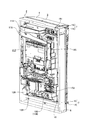
FIG. 4 is a rear view showing the entire rear side of the pachinko machine.
As shown in FIGS. 2 and 3, the game board mounting frame 12 of the main body frame 3 is provided on the rear side of the front frame body 11, and the game board 5 is mounted so as to be attachable / detachable from the front. . The game board 5 is formed in a substantially square plate shape having a size to be fitted from the front of the game board mounting frame 12 (see FIG. 9). A guide rail 78 including an outer rail 76 and an inner rail 77 is provided on the board surface (front surface) of the game board 5, and a game area 37 is defined inside the guide rail 78. A predetermined gap is provided between the launch rail 19 and the guide rail 78, and when the launched game ball returns to the guide rail 78, the game ball is discharged from the gap. It is configured to be guided to the lower plate 31. Further, a front structural member 79 made of synthetic resin is attached to the front surface of the game board 5 in the outer region of the guide rail 78.
一方、図4に示すように、遊技盤5の後側下部には、その中央部から下部にわたる部分において、各種入賞装置に流入した遊技球を受けかつその遊技球を所定位置まで導く集合樋としての機能とボックス装着部としての機能を兼ね備えたボックス装着台91が設けられている。このボックス装着台91には、音声制御基板、ランプ制御基板等の副制御基板92が収納された副制御基板ボックス93が装着され、その副制御基板ボックス93の後側に重ね合わされた状態で、主制御基板94が収納された主制御基板ボックス95が装着されている。さらに、遊技盤5の後側に対しボックス装着台91、副制御基板ボックス93及び主制御基板ボックス95がそれぞれ装着された状態において、本体枠3の遊技盤装着枠12の前方から遊技盤5を嵌込んで装着できるように、遊技盤5の外郭より外側にはみ出すことなくボックス装着台91、副制御基板ボックス93及び主制御基板ボックス95が配置されている。
On the other hand, as shown in FIG. 4, the lower part on the rear side of the game board 5 receives a game ball that has flowed into various winning devices in a portion extending from the center to the lower part, and serves as a collective bag A box mounting base 91 having both the above function and the function as a box mounting portion is provided. A sub-control board box 93 in which a sub-control board 92 such as a sound control board and a lamp control board is housed is mounted on the box mounting base 91 and is superposed on the rear side of the sub-control board box 93. A main control board box 95 in which the main control board 94 is accommodated is mounted. Further, in a state where the box mounting base 91, the sub control board box 93 and the main control board box 95 are respectively mounted on the rear side of the game board 5, the game board 5 is moved from the front of the game board mounting frame 12 of the main body frame 3. The box mounting base 91, the sub control board box 93, and the main control board box 95 are arranged so as not to protrude outward from the outline of the game board 5 so as to be fitted and mounted.
[本体枠の機構装着体、球タンク及びタンクレールの構成について] 図7及び図8に基づき説明する。
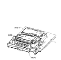
図7はパチンコ機の本体枠に各種部材が組み付けられた状態を斜め右上後方から示す斜視図であり、図8は本体枠単体を斜め右上後方から示す斜視図である。
本体枠3の機構装着体13には、タンク装着部111、レール装着部112、及び払出装置装着部113等がそれぞれ形成され、タンク装着部111には球タンク114が装着されている。球タンク114は、透明な合成樹脂材よりなり、島設備から供給される多数の遊技球が貯留可能な上方に開口する箱形状に形成されている。そして、球タンク114の遊技球の貯留状態が球タンク114の後側壁を透して視認可能となっている。また、球タンク114の底板部115の後側隅部には遊技球を放出する放出口116が形成されるとともに、底板部115は放出口116に向けて下傾する傾斜面に形成されている。
[Configuration of Main Body Frame Mechanism Mounted Body, Ball Tank, and Tank Rail] A description will be given based on FIGS. 7 and 8.
FIG. 7 is a perspective view showing the state in which various members are assembled to the main body frame of the pachinko machine from diagonally upper right rear, and FIG. 8 is a perspective view showing the main body frame from diagonally upper right rear.
A tank mounting portion 111, a rail mounting portion 112, a dispensing device mounting portion 113, and the like are formed on the mechanism mounting body 13 of the main body frame 3, and a ball tank 114 is mounted on the tank mounting portion 111. The ball tank 114 is made of a transparent synthetic resin material, and is formed in a box shape opening upward so that a large number of game balls supplied from the island facility can be stored. The storage state of the game balls in the ball tank 114 is visible through the rear side wall of the ball tank 114. In addition, a discharge port 116 for discharging a game ball is formed at the rear corner of the bottom plate portion 115 of the ball tank 114, and the bottom plate portion 115 is formed on an inclined surface inclined downward toward the discharge port 116. .
本体枠3の機構装着体13には、そのタンク装着部111に下方に接近してレール装着部112が一体に形成され、そのレール装着部112にレール構成部材117が装着されることでタンクレール118が構成されるようになっている。すなわち、この実施形態において、レール装着部111は、本体枠3の上部横方向部分が所定深さ凹まされた状態で形成されており、その凹部の奥側壁をタンクレール118の前壁部119とし、その凹部の下縁部に沿って一端(図8に向かって左端)から他端(図8に向かって右端)に向けて下傾する傾斜状のレール棚120が形成されている。そして、レール棚120の横方向に延びる上向き面をレール受け部121としている。
The mechanism mounting body 13 of the main body frame 3 is integrally formed with a rail mounting portion 112 so as to approach the tank mounting portion 111 downward, and the rail component 117 is mounted on the rail mounting portion 112 so that the tank rail 118 is configured. That is, in this embodiment, the rail mounting portion 111 is formed in a state where the upper lateral direction portion of the main body frame 3 is recessed by a predetermined depth, and the rear side wall of the recess is used as the front wall portion 119 of the tank rail 118. An inclined rail shelf 120 that is inclined downward from one end (left end toward FIG. 8) to the other end (right end toward FIG. 8) is formed along the lower edge of the recess. An upward surface extending in the lateral direction of the rail shelf 120 is used as a rail receiving portion 121.
レール装着部112に装着されてタンクレール118を構成するレール構成部材117は、レール装着部112の前壁部119との間にレール通路を構成する後壁部122と、傾斜状をなす下板部と、その下板部の上面の前後方向中央部に沿って突設されレール通路を前後複数列(この実施形態では前後2列)に区画する仕切り壁(いずれも図示しない)とを一体に備えて形成されている。このレール構成部材117は、レール装着部112に対し適宜の取付手段によって装着され、これによって、前後複数列のレール通路を備えたタンクレール118が構成されている。そして、球タンク114の放出口116から放出(自重によって落下)された遊技球がタンクレール118の前後複数列のレール通路の一端部においてそれぞれ受けられた後、遊技球が自重によってレール通路に沿って転動することでレール通路の他端部に向けて流れるようになっている。また、この実施形態において、レール構成部材117は、透明な合成樹脂材より形成され、これによって、レール通路内の遊技球の流れ状態が、レール構成部材117の後壁部122を透して視認可能となっている。
A rail constituting member 117 which is mounted on the rail mounting portion 112 and constitutes the tank rail 118 includes a rear wall portion 122 which forms a rail passage between the rail mounting portion 112 and the front wall portion 119, and an inclined lower plate And a partition wall (both not shown) that project along the center in the front-rear direction of the upper surface of the lower plate part and divide the rail passage into front and rear rows (in this embodiment, front and rear rows). It is formed in preparation. The rail constituting member 117 is attached to the rail attaching portion 112 by an appropriate attachment means, thereby forming a tank rail 118 having a plurality of front and rear rows of rail passages. Then, after the game balls discharged from the discharge port 116 of the ball tank 114 (falling due to its own weight) are received at one end of the rail passages in the front and rear rows of the tank rail 118, the game balls follow the rail passage by their own weight. And rolling toward the other end of the rail passage. Further, in this embodiment, the rail constituent member 117 is formed of a transparent synthetic resin material, whereby the flow state of the game balls in the rail passage is visually recognized through the rear wall portion 122 of the rail constituent member 117. It is possible.
タンクレール118(レール装着部112)の前壁部119は、遊技盤5の後側に突出する装備品(例えば役物)における後部の上端部との干渉を避けるため第1空間部を隔てた状態で設けられている。また、この実施形態において、本体枠3の後端部となるレール棚120の後端と、タンクレール118の後壁部は、球タンク114の後側壁と略同一面をなしている。言い換えると、球タンク114の後壁部に対しタンクレール118の後壁部が略同一面となる位置までタンクレール118が遊技盤5の後面より後方に離隔して配置されている。これによって、遊技盤5の後側とタンクレール118の前壁部119との間に装備品(例えば役物)の後部との干渉を避けるための第1空間部が設けられるようになっている。
The front wall portion 119 of the tank rail 118 (rail mounting portion 112) is separated from the first space portion in order to avoid interference with the upper end portion of the rear portion of the equipment (for example, an accessory) protruding to the rear side of the game board 5. It is provided in the state. In this embodiment, the rear end of the rail shelf 120 that is the rear end portion of the main body frame 3 and the rear wall portion of the tank rail 118 are substantially flush with the rear side wall of the ball tank 114. In other words, the tank rail 118 is arranged rearwardly from the rear surface of the game board 5 until the rear wall portion of the ball tank 114 is substantially flush with the rear wall portion of the ball tank 114. As a result, a first space portion is provided between the rear side of the game board 5 and the front wall portion 119 of the tank rail 118 to avoid interference with the rear portion of the equipment (for example, an accessory). .
また、タンクレール118の上方には、レール通路を流れる遊技球を上下に重なることなく整列させる整流体123がその上部において軸124を中心として揺動可能に装着されている。この整流体123には、その中央部から下部において錘が設けられている。
Above the tank rail 118, a rectifying body 123 for aligning the game balls flowing in the rail passage without overlapping each other is mounted on the upper portion thereof so as to be swingable about the shaft 124. The rectifier 123 is provided with a weight from the center to the bottom.
[払出装置装着部及び球払出装置の構成について] 図7及び図8に基づき説明する。
本体枠3の機構装着体13の片側寄りの上下方向には、次に述べる球払出装置(球払出ユニット)125に対応する縦長の払出装置装着部113が形成されている。払出装置装着部113は、後方に開口部をもつ凹状に形成されている。また、払出装置装着部113の段差状をなす奥壁部(図示しない)の所定位置には、球払出装置125の払出用モータ126(図3参照)が突出可能な開口部127が形成されている。
[Configurations of Dispensing Device Mounting Unit and Ball Dispensing Device] A description will be given based on FIGS. 7 and 8.
A vertically long paying device mounting portion 113 corresponding to a ball paying device (ball paying unit) 125 described below is formed in the vertical direction of one side of the mechanism mounting body 13 of the main body frame 3. The dispensing device mounting portion 113 is formed in a concave shape having an opening on the rear side. In addition, an opening 127 through which a payout motor 126 (see FIG. 3) of the ball payout device 125 can project is formed at a predetermined position of a back wall portion (not shown) having a stepped shape of the payout device mounting portion 113. Yes.
払出装置装着部113の凹部に球払出装置125が装着された状態において、遊技盤5との間には、第1空間部と前後方向に略同一レベルとなる第2空間部が設けられている。
これによって、レール通路と球通路とが前後方向に略同一レベルで配置されている。また、本体枠3の後端、すなわち払出装置装着部113の周壁部後端、レール棚120の後端、球タンク114、タンクレール118及び球払出装置125のそれぞれの後面は略同一面をなしている。
In a state where the ball payout device 125 is mounted in the recess of the payout device mounting portion 113, a second space portion is provided between the game board 5 and the first space portion that is substantially at the same level in the front-rear direction. .
Thus, the rail passage and the ball passage are arranged at substantially the same level in the front-rear direction. Further, the rear end of the body frame 3, that is, the rear end of the peripheral wall portion of the payout device mounting portion 113, the rear end of the rail shelf 120, the ball tank 114, the tank rail 118, and the ball payout device 125 are substantially the same surface. ing.
球払出装置125は、払出装置装着部113の凹部と略同じ大きさの縦長のボックス形状をなし、払い出しに関する各種部品が装着されることでユニット化されている。なお、球払出装置125は、払出装置装着部113の凹部の後方開口部から嵌込まれて適宜の取付手段(例えば、弾性クリップ、係止爪、ビス等の取付手段)によって装着されるようになっている。
The ball payout device 125 has a vertically long box shape that is substantially the same size as the recess of the payout device mounting portion 113, and is unitized by mounting various components related to payout. The ball payout device 125 is fitted from the rear opening of the recess of the payout device mounting portion 113 and is mounted by appropriate mounting means (for example, mounting means such as an elastic clip, a locking claw, and a screw). It has become.
また、図示しないが、球払出装置125は、タンクレール118におけるレール通路の出口にそれぞれ連通する流入口を有する球通路が前後複数列(例えば前後2列)に区画されて形成されている。また、その内部に形成された前後複数列の球通路の下流部が二股状に分岐されて前後複数列の賞球及び貸球用球通路と球抜き用球通路とがそれぞれ形成されている。そして賞球及び貸球用球通路と球抜き用球通路との分岐部には、遊技球をいずれかの通路に振り分けて払い出すための回転体よりなる払出部材(図示しない)が正逆回転可能に配設されている。
Although not shown, the ball payout device 125 is formed by dividing the ball passages having inflow ports respectively communicating with the outlets of the rail passages in the tank rail 118 into a plurality of front and rear rows (for example, front and rear rows). Also, the downstream portions of the front and rear rows of ball passages formed in the interior are bifurcated to form front and rear rows of prize balls, a ball rental ball passage and a ball removal ball passage. In addition, a payout member (not shown) made of a rotating body for distributing and paying out game balls to any of the passages is rotated in the forward and reverse directions at a branch portion between the winning ball and the ball passage for lending and the ball passage for ball removal. It is arranged to be possible.
[本体枠の後側下部の装備について] 図3及び図4に基づき説明する。
本体枠3の前枠体11の後側において、遊技盤装着枠12よりも下方に位置する前枠体11の後下部領域の片側(図4に向かって左側)には、発射レール19の下傾端部の発射位置に送られた遊技球を発射するための発射ハンマー(図示しない)、その発射ハンマーを作動する発射モータ128等が取付基板129に組み付けられてユニット化された発射装置ユニット130が装着されている。また、前枠体11の後下部領域の略中央部には、電源基板131を収容する電源基板ボックス132が装着され、その電源基板ボックス132の後側に重ね合わされた状態で払出制御基板133を収容する払出制御基板ボックス134が装着されている。払出制御基板133は、遊技球を払い出す数を記憶するRAMを備え、主制御基板94から送信される払出用信号に従って遊技球を払い出す制御信号を中継用回路基板(図示しない)に伝達して払出用モータ126を作動制御するようになっている。ここで、発射装置ユニット130が、本発明の発射装置に相当する。
[Equipment on the lower rear part of the main body frame] A description will be given based on FIGS.
On the rear side of the front frame 11 of the main body frame 3, on one side (left side in FIG. 4) of the rear lower region of the front frame 11 positioned below the game board mounting frame 12, A launching device unit 130 that is assembled with a launching hammer (not shown) for launching a game ball sent to the launching position of the tilted end, a launching motor 128 that operates the launching hammer, and the like, assembled on the mounting substrate 129. Is installed. In addition, a power supply board box 132 that accommodates the power supply board 131 is mounted at a substantially central portion of the rear lower region of the front frame body 11, and the dispensing control board 133 is placed in a state of being superimposed on the rear side of the power supply board box 132. A payout control board box 134 to be accommodated is mounted. The payout control board 133 includes a RAM for storing the number of game balls to be paid out, and transmits a control signal for paying out game balls in accordance with a payout signal transmitted from the main control board 94 to a relay circuit board (not shown). Thus, the operation of the payout motor 126 is controlled. Here, the launcher unit 130 corresponds to the launcher of the present invention.
[後カバー体の構成について] 図4及び図5に基づき説明する。
図5はパチンコ機の後側全体を右上後方から示す斜視図である。
遊技盤5後面に配置された表示装置制御基板ボックス135(図9参照)及び主制御基板ボックス95の後端部は機構装着体13の中央部に開口された窓開口部に向けて突出している。そして、機構装着体13の窓開口部の一側壁を構成する側壁部と他側壁を構成する払出装置装着部113の片側壁との間には、不透明な合成樹脂材によって略方形の箱形状に形成された後カバー体136がカバーヒンジ機構137によって開閉並びに着脱可能に装着されている。
[Configuration of Rear Cover Body] A description will be given based on FIGS. 4 and 5.
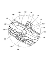
FIG. 5 is a perspective view showing the entire rear side of the pachinko machine from the upper right rear.
The rear end portions of the display device control board box 135 (see FIG. 9) and the main control board box 95 arranged on the rear surface of the game board 5 protrude toward the window opening portion opened in the center portion of the mechanism mounting body 13. . And between the side wall part which comprises one side wall of the window opening part of the mechanism mounting body 13, and the one side wall of the dispensing device mounting part 113 which comprises the other side wall, a substantially square box shape is formed by an opaque synthetic resin material. The formed rear cover body 136 is detachably mounted by a cover hinge mechanism 137.
後カバー体136は、略四角形状の後壁部138と、その後壁部138の外周縁から前方に向けて突出された周壁部139とから一体に構成されている。後カバー体136の周壁部139のうち、一側の壁部139aには、機構装着体13の側壁部の上下及び中間の計3箇所に形成されたヒンジ体140のヒンジ孔の上方からそれぞれ着脱可能に嵌込まれるヒンジピン141を下向きに有するヒンジ体142が一体に形成されている。また、後カバー体136の周壁部139のうち、他側の壁部139bには、払出装置装着部113の片側壁に形成された係止孔に弾性的に係合可能な係止爪を有する弾性閉止体143が一体に形成されている。
The rear cover body 136 is configured integrally with a substantially rectangular rear wall portion 138 and a peripheral wall portion 139 protruding forward from the outer peripheral edge of the rear wall portion 138. Of the peripheral wall portion 139 of the rear cover body 136, the wall portion 139 a on one side is attached and detached from above the hinge holes of the hinge body 140 formed at a total of three positions above and below the side wall portion of the mechanism mounting body 13. A hinge body 142 having a hinge pin 141 that can be fitted downward is integrally formed. Further, of the peripheral wall portion 139 of the rear cover body 136, the other wall portion 139 b has a locking claw that can be elastically engaged with a locking hole formed in one side wall of the dispensing device mounting portion 113. The elastic closing body 143 is integrally formed.
すなわち、後カバー体136は、その上下及び中間のヒンジ体142の各ヒンジピン141が機構装着体13の側壁部のヒンジ体140のヒンジ孔の上方からそれぞれ嵌込まれる。この状態で、ヒンジピン141を中心として後カバー体136が機構装着体13の他側に向けて回動されながら、その弾性閉止体143を払出装置装着部113の片側壁の係止孔に差し込んで弾性的に係合させることで、機構装着体13の後側に後カバー体136が閉じ状態で保持される。そして、後カバー体136によって、遊技盤5後面の表示装置制御基板ボックス135(図9参照)全体及び主制御基板ボックス95の略中間部から上端にわたる部分が後カバー体136によって覆われるようになっている。これによって、主制御基板ボックス95の上部に露出された主制御基板94の基板コネクタ(主として表示装置制御基板と接続するための基板コネクタ)が後方から視認不能に隠蔽されている。
That is, in the rear cover body 136, the hinge pins 141 of the upper and lower and intermediate hinge bodies 142 are respectively fitted from above the hinge holes of the hinge body 140 of the side wall portion of the mechanism mounting body 13. In this state, the rear cover body 136 is rotated toward the other side of the mechanism mounting body 13 around the hinge pin 141, and the elastic closing body 143 is inserted into the locking hole on one side wall of the dispensing device mounting portion 113. The rear cover body 136 is held in a closed state on the rear side of the mechanism mounting body 13 by being elastically engaged. Then, the rear cover body 136 covers the entire display device control board box 135 (see FIG. 9) on the rear surface of the game board 5 and a portion extending from the substantially middle portion to the upper end of the main control board box 95 by the rear cover body 136. ing. As a result, the board connector of the main control board 94 exposed to the upper part of the main control board box 95 (mainly a board connector for connecting to the display apparatus control board) is hidden from view from behind.
また、主制御基板ボックス95の略中間部から下端にわたる部分は後カバー体136によって覆われることなく露出されている。そして、主制御基板ボックス95の下部には、その主制御基板94上に配置された検査用コネクタ144が露出されており、後カバー体136が閉じられた状態で主制御基板94上の検査用コネクタ144に基板検査装置(図示しない)を接続して検査可能となっている。
Further, a portion from the substantially middle portion to the lower end of the main control board box 95 is exposed without being covered by the rear cover body 136. An inspection connector 144 disposed on the main control board 94 is exposed at the lower portion of the main control board box 95, and the inspection connector on the main control board 94 is closed with the rear cover body 136 closed. A board inspection device (not shown) can be connected to the connector 144 for inspection.
後カバー体136には、多数の放熱孔145、146、147、148が貫設されており、これら多数の放熱孔145、146、147、148から内部の熱が放出されるようになっている。この実施形態において、後カバー体136には、その周壁部139から後壁部138に延びる多数のスリット状の放熱孔145が貫設され、後壁部138の略中間高さ位置から上部においては多数の長円形、楕円形等の放熱孔146が貫設され、後壁部138の下部には多数の長円形、楕円形等の放熱孔147と所定数の横長四角形状の放熱孔148が貫設されている。
A large number of heat radiation holes 145, 146, 147, and 148 are provided in the rear cover body 136, and internal heat is released from the large number of heat radiation holes 145, 146, 147, and 148. . In this embodiment, the rear cover body 136 is provided with a number of slit-like heat radiation holes 145 extending from the peripheral wall portion 139 to the rear wall portion 138, and from the substantially middle height position of the rear wall portion 138 to the upper portion. A large number of elliptical, elliptical, etc. heat radiation holes 146 are provided therethrough, and a large number of elliptical, elliptical, etc. heat radiation holes 147 and a predetermined number of laterally rectangular heat radiation holes 148 pass through the lower portion of the rear wall 138. It is installed.
また、横長四角形状の放熱孔148は、主制御基板ボックス95の封印ねじ(封印部材)によって封印される複数の並列状の封印部149の列の大きさ及び配設位置に対応する大きさ及び位置に貫設されている。これによって、不透明な後カバー体136が閉じられた状態であっても、主制御基板ボックス95の複数の並列状の封印部149が放熱孔148の部分において視認可能に露出される。このため、後カバー体136が閉じられた状態であっても、主制御基板ボックス95の封印部149の封印状態を容易に視認することができる。また、不透明な合成樹脂材は、透明な合成樹脂材と比べ、リサイクル使用される合成樹脂材を材料として用いることが容易であるため、後カバー体136を安価に製作することができる。
Further, the horizontally elongated rectangular heat radiation hole 148 has a size corresponding to the size and arrangement position of a plurality of parallel seal portions 149 sealed by the seal screw (sealing member) of the main control board box 95. It penetrates the position. As a result, even when the opaque rear cover body 136 is closed, the plurality of parallel sealing portions 149 of the main control board box 95 are exposed so as to be visible at the portion of the heat radiation hole 148. For this reason, even when the rear cover body 136 is closed, the sealing state of the sealing portion 149 of the main control board box 95 can be easily visually confirmed. In addition, since the opaque synthetic resin material can be easily used as a synthetic resin material that is recycled compared to the transparent synthetic resin material, the rear cover body 136 can be manufactured at low cost.
後カバー体136の周壁部139のうち、上側壁部139cの所定位置(この実施形態では左右2箇所)には、電源コード(図示しない)を適宜に折り畳んだ状態で保持する略C字状でかつ弾性変形可能なコード保持体150が上方のタンクレール118の後壁面(レール構成部材117の後壁面)に向けて延出されている。このコード保持体150の先端部には、同コード保持体150を弾性変形させて電源コードを取り外すためのつまみが形成されている。
Of the peripheral wall portion 139 of the rear cover body 136, at a predetermined position (two places on the left and right in this embodiment) of the upper side wall portion 139c, a power cord (not shown) is held in a substantially folded state so as to be appropriately folded. An elastically deformable cord holder 150 extends toward the rear wall surface of the upper tank rail 118 (the rear wall surface of the rail component member 117). A knob for removing the power cord by elastically deforming the cord holder 150 is formed at the tip of the cord holder 150.
電源コードは、その一端が分電基板151の基板コネクタ152に取り外し可能に接続され、他端の電源プラグが電源コンセントに差し込まれる。前記したように、後カバー体136にコード保持体150を一体に形成して電源コードを保持することで、パチンコ機1を運搬、保管する際に電源コードがぶらついて邪魔になったり、異物に引っ掛かる不具合を防止することができる。
One end of the power cord is detachably connected to the board connector 152 of the distribution board 151, and the power plug at the other end is inserted into a power outlet. As described above, by forming the cord holder 150 integrally with the rear cover body 136 and holding the power cord, the power cord hangs when the pachinko machine 1 is transported and stored, or it may become an obstacle. The trouble which is caught can be prevented.
[本体枠の後側下部の下皿用球誘導体等の構成について] 図1及び図6に基づき説明する。
図6は、図5に示すパチンコ機の斜視図から後カバー体及び各種制御基板等を取り外した状態を示す斜視図である。
本体枠3の後下部領域の他側寄り部分(ヒンジ寄り部分)には、そのスピーカボックス部16の後段差部の凹み部分において下皿用球誘導体153が装着されている。この下皿用球誘導体153は、球払出装置125の賞球及び貸球用球通路から上皿連絡路(図示しない)を経て上皿51に払い出された遊技球が満杯になったときに、上皿連絡路の遊技球を下皿31に導くためのものである。
[Configuration of Sphere Derivative for Lower Plate, etc. at Lower Lower Side of Main Body Frame] A description will be given based on FIGS. 1 and 6.
6 is a perspective view showing a state in which the rear cover body and various control boards are removed from the perspective view of the pachinko machine shown in FIG.
A lower dish ball derivative 153 is attached to the other side portion (hinge portion) of the rear lower region of the main body frame 3 in the recessed portion of the rear stepped portion of the speaker box portion 16. The lower tray ball derivative 153 is used when the game balls paid out to the upper plate 51 through the upper plate connection path (not shown) from the winning ball and rental ball passage of the ball dispensing device 125 are full. The game ball on the upper plate communication path is for guiding the game ball to the lower plate 31.
なお、この実施形態において、下皿用球誘導体153の後壁外面には、インタフェース基板154を収納している基板ボックス155が装着されている。なお、インタフェース基板154は、パチンコ機1に隣接して設置される球貸機と払出制御基板133との間に介在され、球貸に関する信号を球貸機と払出制御基板133との間で送受信可能に電気的に接続するようになっている。
In this embodiment, a board box 155 that houses the interface board 154 is mounted on the outer surface of the rear wall of the lower dish ball derivative 153. The interface board 154 is interposed between the ball lending machine installed adjacent to the pachinko machine 1 and the payout control board 133, and transmits / receives a signal related to ball lending between the ball lending machine and the payout control board 133. Electrical connection is possible.
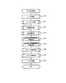
[遊技盤の構成について] 図10〜図14に基づき説明する。
図10は遊技領域を有する遊技盤と、その遊技盤に装着された複数のユニットとを組付けたパチンコ主要部の構成を示す拡大正面図であり、図11はパチンコ主要部を左上前方から示す斜視図であり、図12はパチンコ主要部を右上前方から示す斜視図であり、図13は遊技領域を有する遊技盤を右上前方から示す斜視図であり、図14はパチンコ主要部を分解して斜め前方から示す分解斜視図である。
[Configuration of Game Board] The game board will be described with reference to FIGS.
FIG. 10 is an enlarged front view showing the configuration of a pachinko main part in which a game board having a game area and a plurality of units mounted on the game board are assembled, and FIG. 11 shows the pachinko main part from the upper left front. FIG. 12 is a perspective view showing a pachinko main portion from the upper right front, FIG. 13 is a perspective view showing a game board having a game area from the upper right front, and FIG. 14 is an exploded pachinko main portion. It is a disassembled perspective view shown from diagonally forward.
図13に示すように、遊技盤5は、略円形の開口210を有する前構成部材211と、前面側に前構成部材211が取り付けられると共に前構成部材211と同様の形状の開口(図示しない)を有する遊技盤ベース212と、前構成部材211及び遊技盤ベース212の間に挟まれ、前構成部材211の開口210及び遊技盤ベース212の開口を閉鎖する透明の遊技領域板81とを具備して構成されている。そして、遊技領域板81の表面には、開口210内に遊技球を案内する外レール76及び内レール77からなる案内レール78、主入賞口ユニット214、及び通過ゲート69等が取付けられ、遊技領域板81の形成された開口部82には額縁状のセンター役物230を有する主役物213が取付けられている。つまり、開口210で囲まれた遊技領域板81の表面に遊技領域37が区画形成されており、この遊技領域37内には、多数の障害釘(図示しない)が所定のゲージ配列をなして設けられているほか、その途中の適宜位置に、上述の主役物213、通過ゲート69、及び主入賞口ユニット214等が配置されている。なお、遊技領域37内の中央最下部には、入賞口等に入賞しなかった遊技球を遊技領域37内から排出するアウト口220が設けられている。なお、通過ゲート69には、通過ゲート69に遊技球が通過したことを検出するゲートセンサ990(図40参照)が設けられている。
As shown in FIG. 13, the game board 5 has a front component member 211 having a substantially circular opening 210, and a front component member 211 attached to the front side and an opening having the same shape as the front component member 211 (not shown). And a transparent game area plate 81 which is sandwiched between the front component member 211 and the game board base 212 and which closes the opening 210 of the front component member 211 and the opening of the game board base 212. Configured. On the surface of the game area plate 81, a guide rail 78 including an outer rail 76 and an inner rail 77 for guiding a game ball into the opening 210, a main winning port unit 214, a passing gate 69, and the like are attached. A main character 213 having a frame-shaped center character 230 is attached to the opening 82 in which the plate 81 is formed. That is, the game area 37 is defined on the surface of the game area plate 81 surrounded by the opening 210, and a number of obstacle nails (not shown) are provided in the game area 37 in a predetermined gauge arrangement. In addition, the above-mentioned main character 213, the passage gate 69, the main winning a prize opening unit 214, and the like are arranged at appropriate positions in the middle of the above. Note that an out-port 220 is provided at the lowermost center of the game area 37 to discharge game balls that have not won a prize-winning hole or the like from the game area 37. The passage gate 69 is provided with a gate sensor 990 (see FIG. 40) that detects that a game ball has passed through the passage gate 69.
遊技領域板81は、ポリカーボネイト樹脂、ポリアリレート樹脂、アクリル樹脂、メタクリル樹脂等の樹脂材料に弾性樹脂材料(本実施品はゴム)を所定割合含有させた透明な樹脂を、押出し成形して形成されていると共に、その押出し方向が上下方向に対して交わる方向となるように形成されている。遊技領域板81を構成する樹脂材料に弾性樹脂材料を含有させることにより、障害釘等が遊技領域板81に打設されてもクラックが入ることがなくなると共に、流下する遊技球などによるキズも抑制する事ができ、遊技者の興趣が低下するのを防止することができる。なお、押出し方向を上下方向に対して約45度の方向となるように形成することが望ましい。また、遊技領域板81の厚さは、打設される障害釘などを充分に保持することのできる必要最低限の厚さ(8〜10mm)とされており、遊技盤ベース212の厚さの略半分の厚さとされている。
The game area plate 81 is formed by extruding a transparent resin containing a predetermined proportion of an elastic resin material (rubber in this embodiment) in a resin material such as polycarbonate resin, polyarylate resin, acrylic resin, methacrylic resin or the like. In addition, the extrusion direction is formed so as to intersect the vertical direction. By including an elastic resin material in the resin material constituting the game area board 81, cracks are prevented from entering even if obstacle nails or the like are driven into the game area board 81, and the damage caused by the game balls flowing down is also suppressed. It is possible to prevent the player's interest from deteriorating. In addition, it is desirable to form so that an extrusion direction may be about 45 degree | times with respect to an up-down direction. Further, the thickness of the game area plate 81 is set to a minimum necessary thickness (8 to 10 mm) that can sufficiently hold the obstacle nail to be placed, and the thickness of the game board base 212 The thickness is almost half.
これにより、遊技領域板81の押出し方向が上下方向に対して交わる方向、つまり、押出し方向が上下方向以外の方向となるように形成されているので、例えば、遊技領域板81の後方に演出表示装置101(図10参照)や装飾体84(図14参照)等を配置した場合、遊技領域板81と演出表示装置101や装飾体84等のドットマトリックスとが干渉して、モアレが発生するのを可及的に抑制することができ、モアレにより演出表示装置101や装飾体84等が見辛くなるのを防止することができる。
As a result, the direction in which the game area plate 81 is pushed out intersects the vertical direction, that is, the direction in which the push direction is a direction other than the vertical direction. When the device 101 (see FIG. 10), the decorative body 84 (see FIG. 14), etc. are arranged, the game area board 81 interferes with the dot matrix of the effect display device 101, the decorative body 84, etc., and moire occurs. Can be suppressed as much as possible, and it is possible to prevent the presentation display device 101 and the decorative body 84 from becoming difficult to see due to moire.
また、図14、及び図10〜図12に示すように、遊技盤5の後側には、枠状のベース部材83及びそのベース部材83の表面に取付けられた複数の装飾体84を具備し、透明な遊技領域板81を通して内部の装飾体領域600が視認可能な電飾ユニット85と、遊技領域板81の形成された開口部82を通して視認可能な可動役物87、及びその可動役物87を駆動させる可動機構部88を具備する可動装飾ユニット89と、可動装飾ユニット89の枠開口部521に対して後方から嵌込まれ開口部82を通して視認可能な演出表示装置101とが組付けられている。ここで、装飾体84が本発明の立体装飾体に相当する。
Further, as shown in FIGS. 14 and 10 to 12, on the rear side of the game board 5, a frame-like base member 83 and a plurality of decorative bodies 84 attached to the surface of the base member 83 are provided. The electric decoration unit 85 in which the internal decoration body region 600 can be visually recognized through the transparent game area plate 81, the movable accessory 87 visible through the opening 82 in which the game region plate 81 is formed, and the movable accessory 87 A movable decorative unit 89 having a movable mechanism 88 for driving the frame and an effect display device 101 that is fitted from the rear to the frame opening 521 of the movable decorative unit 89 and visible through the opening 82 are assembled. Yes. Here, the decorative body 84 corresponds to the three-dimensional decorative body of the present invention.
(主役物の構成について)
次に、遊技盤5における主役物213の具体的な構成について、図15〜図17に基づき詳細に説明する。図15は主役物を右上前方から示す斜視図であり、図16はセンター役物のステージを右上前方から示す拡大斜視図であり、図17はセンター役物のステージを左上後方から示す拡大斜視図である。
(About the composition of the main character)
Next, a specific configuration of the main character 213 in the game board 5 will be described in detail with reference to FIGS. 15 is a perspective view showing the main character from the upper right front, FIG. 16 is an enlarged perspective view showing the stage of the center character from the upper right front, and FIG. 17 is an enlarged perspective view showing the stage of the center character from the upper left rear. It is.
図15に示すように、遊技盤5における主役物213は、額縁状に形成されたセンター役物230と、センター役物230の右側前面に取り付けられ光を透過可能な文字表示体231と、センター役物230の左側の下縁部に取付けられた風車219とを備えている。
As shown in FIG. 15, the main character 213 in the game board 5 includes a center character 230 formed in a frame shape, a character display body 231 that is attached to the right front surface of the center character 230 and can transmit light, And a windmill 219 attached to the lower edge of the left side of the accessory 230.
センター役物230は、光透過性の部材からなるが、その表面には部分的に光を透過させない鏡面加工部104が形成されている。また、センター役物230の左側の側縁部には、センター役物230の外側に開口した第一ワープ入口105と、センター役物230の内側に開口した第一ワープ出口106とを有し、第一ワープ入口105及び第一ワープ出口106を連通する第一ワープ通路107が形成されている。また、同様に第一ワープ通路107の下方には、第一ワープ通路107とは区画されたワープ通路として、第二ワープ入口160及び第二ワープ出口161を有する第二ワープ通路162が形成されている。なお、第一ワープ出口106及び第二ワープ出口161は、センター役物230の背面下部に取付けられたワープ通路形成部材163によって、センター役物230の下縁部近傍まで延出されており、さらに第一ワープ出口106が第二ワープ出口161よりも後側(すなわち遊技者と反対側)になるように形成されている。つまり、センター役物230の外側(左側)の遊技領域37を転動する遊技球が、上側の第一ワープ入口105に入球した場合には、センター役物230の下縁部の奥側に送られ、一方、下側の第二ワープ入口160に入球した場合には、下縁部の手前側(遊技者側)に送られるようになっている。
The center accessory 230 is made of a light-transmitting member, but a mirror-finished portion 104 that does not partially transmit light is formed on the surface thereof. The left side edge of the center accessory 230 has a first warp inlet 105 that opens to the outside of the center accessory 230 and a first warp outlet 106 that opens to the inside of the center accessory 230, A first warp passage 107 communicating with the first warp inlet 105 and the first warp outlet 106 is formed. Similarly, a second warp passage 162 having a second warp inlet 160 and a second warp outlet 161 is formed below the first warp passage 107 as a warp passage partitioned from the first warp passage 107. Yes. The first warp outlet 106 and the second warp outlet 161 are extended to the vicinity of the lower edge of the center accessory 230 by a warp passage forming member 163 attached to the lower back of the center accessory 230. The first warp outlet 106 is formed behind the second warp outlet 161 (that is, on the side opposite to the player). That is, when a game ball rolling in the game area 37 on the outer side (left side) of the center accessory 230 enters the upper first warp inlet 105, On the other hand, when the ball enters the second warp inlet 160 on the lower side, it is sent to the front side (player side) of the lower edge portion.
また、センター役物230には、その下縁部における上面に、第一ワープ通路107の第一ワープ出口106から供給される遊技球を左右方向に転動させることのできる第一棚部165と、第二ワープ通路162の第二ワープ出口161から供給される遊技球を左右方向に転動させることのできる第二棚部166とからなる転動面167を備えたステージ164が備えられている。なお、第一棚部165と第二棚部166との間には段差172が形成され、第一棚部165よりも第二棚部166が低くなっている。つまり、第二棚部166は、第一棚部165よりも遊技者側であって、第一棚部165よりも遊技球の流下方向において下流側に配置されている。
Further, the center accessory 230 has a first shelf 165 that can roll a game ball supplied from the first warp outlet 106 of the first warp passage 107 in the left-right direction on the upper surface of the lower edge portion thereof. A stage 164 having a rolling surface 167 including a second shelf 166 capable of rolling the game ball supplied from the second warp outlet 161 of the second warp passage 162 in the left-right direction is provided. . A step 172 is formed between the first shelf 165 and the second shelf 166, and the second shelf 166 is lower than the first shelf 165. That is, the second shelf portion 166 is disposed on the player side with respect to the first shelf portion 165, and is disposed on the downstream side in the flow direction of the game ball with respect to the first shelf portion 165.
図16及び図17に示すように、第一棚部165には、中央側に向って次第に低くなる曲面部168と、第一棚部165の中央に設けられ上方に隆起した高台部169とが形成されており、遊技球を曲面部168に沿って左右方向に繰返し転動させるとともに、勢いの弱くなった遊技球が第一棚部165の中央部分に集中することを回避している。また、高台部169の中央には、第一棚部165において左右方向に転動する遊技球を、後方に向って案内する凹状の案内溝170が形成されており、また、高台部169の前縁部分には、遊技球が第一棚部165から第二棚部166に向って排出されることを防止する所定高さの堰部173が立設されている。
As shown in FIGS. 16 and 17, the first shelf 165 includes a curved surface portion 168 that gradually decreases toward the center side, and a hill portion 169 that is provided at the center of the first shelf 165 and is raised upward. Thus, the game ball is repeatedly rolled in the left-right direction along the curved surface portion 168, and the concentration of the game ball having weakened momentum on the central portion of the first shelf portion 165 is avoided. In addition, a concave guide groove 170 that guides a game ball that rolls in the left-right direction in the first shelf 165 toward the rear is formed in the center of the hill portion 169. A dam portion 173 having a predetermined height that prevents the game ball from being discharged from the first shelf portion 165 toward the second shelf portion 166 is provided upright at the edge portion.
また、ステージ164の中央部分には、第一棚部165から後方に突出して設けられた入賞装置受入部177が、ステージ164と一体で形成されており、第一棚部165の高台部169上で転動する遊技球を受入れて、第一始動口装置456(後述する)に入球させることを可能としている。このように、入賞装置受入部177が第一棚部165から突出して設けられているため、第一始動口装置456とステージ164とが互いに関連付けられて、第一棚部165上で転動する遊技球が入賞装置受入部177に受入れられるか否かについて、興趣を高めることが可能になる。また、この際、入賞装置受入部177への遊技球の受入が、センター役物230の外側を転動する遊技球によって阻害されることがないため、ステージ164の最適位置から流下する際に発生する期待感を維持することができるとともに、期待感の消失による不安を拭い去ることができる。
In addition, a winning device receiving portion 177 that protrudes rearward from the first shelf portion 165 is formed integrally with the stage 164 at the center portion of the stage 164, and is located on the hill portion 169 of the first shelf portion 165. It is possible to accept the game ball that rolls at, and enter the first starter device 456 (described later). Thus, since the winning device receiving portion 177 is provided so as to protrude from the first shelf portion 165, the first starter device 456 and the stage 164 are associated with each other and roll on the first shelf portion 165. It is possible to enhance the interest as to whether or not the game ball is received by the winning device receiving unit 177. Further, at this time, since the game ball receiving into the winning device receiving unit 177 is not hindered by the game ball rolling outside the center accessory 230, it occurs when flowing down from the optimal position of the stage 164. It is possible to maintain a sense of expectation and to wipe away anxiety due to the loss of expectation.
入賞装置受入部177は、第一棚部165から後方に向って略水平方向に延出され下面が開放されたアーチ状のガイド部178と、そのガイド部178を覆うとともに斜め上方に延出された板状の上面部179とから構成されている。このため、入賞装置受入部177に入球した遊技球を、ガイド部178に沿って確実に送込むことが可能になる。つまり、入賞装置受入部177に入球した遊技球の勢いが強い場合でも、左右方向の側面から逸脱したり、飛越えたりすることを防止し、滑らかに入球させることが可能になる。また、アーチ形のガイド部178は第一棚部165よりも上方に突出して設けられることとなるが、ガイド部178を覆うように上面部179が形成され、しかも斜め上方に延設するように傾斜して設けられているため、第一棚部165との一体感を印象づけることができるとともに、上面部179によって入賞装置受入部177を大きく見せ目立たせることができる。
The winning device receiving portion 177 extends from the first shelf portion 165 rearward in a substantially horizontal direction and has an arch-shaped guide portion 178 whose bottom surface is open, and covers the guide portion 178 and extends obliquely upward. And a plate-shaped upper surface portion 179. For this reason, it is possible to reliably send the game ball that has entered the winning device receiving unit 177 along the guide unit 178. That is, even when the game ball that has entered the winning device receiving unit 177 has a strong momentum, it is possible to prevent the ball from deviating from or jumping over from the side surface in the left-right direction and smoothly enter the ball. In addition, the arch-shaped guide part 178 is provided so as to protrude upward from the first shelf part 165, but an upper surface part 179 is formed so as to cover the guide part 178, and extends obliquely upward. Since it is provided with an inclination, it is possible to impress a sense of unity with the first shelf 165 and to make the winning device receiving portion 177 large and conspicuous by the upper surface portion 179.
一方、第二棚部166には、中央側に向って次第に低くなる曲面部182が形成されており、遊技球を左右方向に繰返し転動させることが可能になっている。なお、この第二棚部166に対しては、第二ワープ通路162を通って直接遊技球が供給される場合と、第一棚部165から排出された遊技球が供給される場合とがある。また、第二棚部166の中央部分には、第二棚部166上の遊技球を、主入賞口ユニット214(図13参照)の略中央直上に流下するように誘導する誘導路183を更に備えている。この誘導路183は、第二棚部166の略中央に配置され遊技球を第二棚部166の後側へ案内する凹状の球案内部184と、球案内部184の下方且つ第二棚部166の後側に延出し上方から遊技球を受入可能とする球受部185と、球受部185に受けられた遊技球を球案内部184の下方且つ第二棚部166の前側に開口する球流出口186から流出するように誘導する球誘導部187とから構成されている。なお、第一棚部165と第二棚部166との間、並びに第二棚部166の前縁における所定の箇所には、第一棚部165または第二棚部166から遊技球が逸脱することを規制する所定高さの堰部188が部分的に設けられている。
On the other hand, the second shelf portion 166 is formed with a curved surface portion 182 that gradually decreases toward the center side, and the game ball can be repeatedly rolled in the left-right direction. The second shelf 166 may be supplied with game balls directly through the second warp passage 162 or may be supplied with game balls discharged from the first shelf 165. . In addition, a guide path 183 for guiding the game ball on the second shelf 166 to flow down directly above the center of the main winning opening unit 214 (see FIG. 13) is further provided in the central portion of the second shelf 166. I have. The guide path 183 is disposed substantially at the center of the second shelf 166 and guides the game ball to the rear side of the second shelf 166, and the second shelf below the ball guide 184 and the second shelf. A ball receiving portion 185 that extends to the rear side of 166 and can receive a game ball from above, and a game ball received by the ball receiving portion 185 is opened below the ball guide portion 184 and to the front side of the second shelf portion 166. It is comprised from the ball | bowl guidance | guide part 187 which guides so that it may flow out from the ball | bowl outflow port 186. Note that the game ball deviates from the first shelf 165 or the second shelf 166 between the first shelf 165 and the second shelf 166 and at predetermined positions on the front edge of the second shelf 166. A weir portion 188 having a predetermined height that restricts this is partially provided.
また、ステージ164は光を透過させない不透明な部材を基本部材として形成されているが、前後方向に延びる帯状の光透過部(図示しない)が、左右方向において所定の間隔で配置されており、光透過部から光を放射させることが可能になっている。また、第一棚部165と第二棚部166との間に設けられた堰部188(図15参照)も光透過性部材で形成され、後方から放射される光を透過させることが可能になっている。なお、その堰部188は、内部に複数のスリットを有し、装飾性の高いものとなっている。
Further, the stage 164 is formed using an opaque member that does not transmit light as a basic member, but strip-shaped light transmitting portions (not shown) extending in the front-rear direction are arranged at predetermined intervals in the left-right direction. Light can be emitted from the transmission part. Further, the weir 188 (see FIG. 15) provided between the first shelf 165 and the second shelf 166 is also formed of a light transmissive member, and can transmit light emitted from the rear. It has become. In addition, the dam part 188 has a plurality of slits inside and is highly decorative.
(主入賞口ユニットの構成について)
次に、主入賞口ユニット214の構成について、図13に基づいて詳細に説明する。まず、主入賞口ユニット214は、センター役物230の下方における遊技領域37の左右方向略中央部分に配置され、上方に開口するポケット形の第二始動口装置330と、第二始動口装置330の下方に配置され第二始動口装置330と一対の可動片331とで閉鎖又は開放可能な第三始動口装置332と、第三始動口装置332の下方に配置され左右方向に延びる矩形状の大入賞口(図示しない)及び大入賞口を閉鎖可能とし上辺が前方に回動する開閉扉334を有したアタッカ装置335と、アタッカ装置335の左右両側に配置され互いに離反するように斜め上方に開口する一般入賞口336とを備えている。なお、第二始動口装置330及び第三始動口装置332は、いずれも、遊技球を受け入れるための受入部と、受け入れた遊技球を案内する入球通路とから構成されている。また、一般入賞口336は、遊技者側に突出する部分の先端面が閉鎖されるとともに上面が開放された円筒状の部材からなり、遊技領域板81を貫通して設けられている。
(About the composition of the main prize opening unit)
Next, the configuration of the main winning a prize opening unit 214 will be described in detail with reference to FIG. First, the main winning opening unit 214 is disposed at a substantially central portion in the left-right direction of the game area 37 below the center accessory 230, and has a pocket-shaped second starting port device 330 that opens upward, and a second starting port device 330. A third starter device 332 that can be closed or opened by a second starter device 330 and a pair of movable pieces 331, and a rectangular shape that is disposed below the third starter device 332 and extends in the left-right direction. An attacker device 335 having an open / close door 334 whose upper side is capable of closing a grand prize opening (not shown) and a grand prize opening, and the diagonally upward so as to be spaced apart from each other. And a general winning opening 336 that opens. Note that each of the second starter device 330 and the third starter device 332 includes a receiving part for receiving a game ball and a ball path for guiding the received game ball. Further, the general winning opening 336 is formed of a cylindrical member whose front end surface protruding to the player side is closed and whose upper surface is opened, and is provided through the game area plate 81.
また、主入賞口ユニット214は、第三始動口装置332を開閉する一対の可動片331を開閉駆動させる始動口開閉駆動ユニット(図示しない)を更に備えている。この始動口開閉駆動ユニットは、前後方向に進退可能なプランジャを有した始動口ソレノイドと、始動口ソレノイドにおけるプランジャの前後方向の進退に伴って水平方向且つ左右方向(遊技盤面に沿った方向)に延びる軸周りに回動し、一対の可動片331から後側に延在された突出ピンを上下方向に移動可能な伝達部材とを備えている。
The main winning port unit 214 further includes a start port opening / closing drive unit (not shown) that opens and closes a pair of movable pieces 331 that open and close the third start port device 332. The start port opening / closing drive unit includes a start port solenoid having a plunger that can be moved back and forth in the front-rear direction, and in a horizontal direction and a left-right direction (a direction along the game board surface) as the plunger moves forward and backward in the start port solenoid. A transmission member that rotates around an extending axis and is capable of moving a protruding pin extending rearward from the pair of movable pieces 331 in the vertical direction.
また、始動口ソレノイドの下側には第二始動口センサ358(図40参照)が備えられており、第二始動口装置330または第三始動口装置332に入賞した遊技球が、第二始動口センサ358の貫通孔を通過することで第二始動口センサ358に検出されると共に、主入賞口ユニット214の下側に形成された排出口から排出されるようになっている。
Further, a second start port sensor 358 (see FIG. 40) is provided below the start port solenoid, and a game ball won in the second start port device 330 or the third start port device 332 receives a second start. By passing through the through hole of the mouth sensor 358, it is detected by the second starting port sensor 358 and discharged from the outlet formed below the main winning port unit 214.
また、主入賞口ユニット214のアタッカ装置335は、大入賞口に入賞した遊技球を検出する大入賞口センサ370(図40参照)と、大入賞口を閉鎖可能な左右方向に延びる矩形状とされ下辺側が軸支されると共に上辺側が直立状態から前方に回動可能とされた開閉扉334と、前後方向に進退可能なプランジャを有したアタッカソレノイド(図示しない)と、アタッカソレノイドにおけるプランジャの前後方向の進退に伴って水平方向且つ左右方向(遊技盤面に沿った方向)に延びる軸周りに回動して開閉扉334を回動させる伝達部材と、大入賞口センサ370、開閉扉334、及びアタッカソレノイド等を支持すると共に大入賞口に入賞した遊技球を大入賞口センサ370で検出されるように誘導する誘導路を有したケーシング(いずれも図示しない)とを備えている。
Also, the attacker device 335 of the main winning opening unit 214 includes a large winning opening sensor 370 (see FIG. 40) that detects a game ball that has won a big winning opening, and a rectangular shape extending in the left-right direction that can close the large winning opening. The open / close door 334 is pivotally supported on the lower side and is pivotable forward from the upright side, an attacker solenoid (not shown) having a plunger that can be moved back and forth in the front-rear direction, and the front and rear of the plunger in the attacker solenoid. A transmission member that rotates around an axis extending in the horizontal direction and the left-right direction (the direction along the game board surface) as the direction advances and retreats, a prize winning opening sensor 370, the opening / closing door 334, and A casing having a guiding path that supports an attacker solenoid and the like and guides a game ball that has won a prize-winning opening so as to be detected by the prize-winning opening sensor 370 ( Deviation also has a do not) and shown.
なお、このアタッカ装置335は、大入賞口の左右方向の幅が、一対の可動片331が開状態となり第三始動口装置332が開放状態となった時の幅よりも、更に広い幅とされており、遊技球がより入賞し易いようになっている。また、大入賞口から進入し大入賞口センサ370で検出された遊技球は、そのまま主入賞口ユニット214の下方へ排出されるようになっている。
The attacker device 335 has a wider width in the left-right direction than the width when the pair of movable pieces 331 are opened and the third starter device 332 is opened. The game balls are easier to win. In addition, the game ball that enters from the big prize opening and is detected by the big prize opening sensor 370 is discharged as it is below the main prize opening unit 214.
また、主入賞口ユニット214は、その第二始動口装置330が、主役物213の誘導路183における球流出口186(図16参照)の直下に位置するように遊技盤ベース212に取付固定されており、誘導路183から流出した遊技球が、主入賞口ユニット214の第二始動口装置330に入賞する可能性が高くなるように配置されている。
Further, the main winning opening unit 214 is attached and fixed to the game board base 212 so that the second starting port device 330 is located immediately below the ball outlet 186 (see FIG. 16) in the guide path 183 of the main character 213. The game balls that have flowed out of the guide path 183 are arranged so as to increase the possibility that they will win the second starting port device 330 of the main winning port unit 214.
(電飾ユニットについて)
次に、電飾ユニット85の構成について、図18乃至図28に基づいて詳細に説明する。図18は電飾ユニットを右上前方から示す斜視図であり、図19は電飾ユニットのベース部材を右上前方から示す斜視図であり、図20は電飾ユニットに設けられた各装飾体を示す正面図であり、図21はステージ及び発光装飾装置を右上前方から示す拡大斜視図であり、図22は電飾ユニットのベース部材に装着された発光基板及び発光装飾体を示す正面図であり、図23は図10におけるA−A間の断面を示す断面図であり、図24は図10におけるB−B間の断面を示す断面図であり、図25は図10におけるC−C間の断面を示す断面図であり、図26は電飾ユニットを示す背面図であり、図27は電飾ユニットから隔壁板及びセンター役物を分離した状態を左上後方から示す分解斜視図であり、図28はセンター役物と電飾ユニットとの組付け状態を示す断面図である。
(About the lighting unit)
Next, the structure of the electrical decoration unit 85 will be described in detail with reference to FIGS. 18 is a perspective view showing the electric decoration unit from the upper right front, FIG. 19 is a perspective view showing the base member of the electric decoration unit from the upper right front, and FIG. 20 shows each decorative body provided in the electric decoration unit. 21 is a front view, FIG. 21 is an enlarged perspective view showing the stage and the light emitting decoration device from the upper right front, and FIG. 22 is a front view showing the light emitting substrate and the light emitting decoration mounted on the base member of the electric decoration unit, 23 is a cross-sectional view showing a cross-section between AA in FIG. 10, FIG. 24 is a cross-sectional view showing a cross-section between BB in FIG. 10, and FIG. 25 is a cross-section between CC in FIG. 26 is a rear view showing the electric decoration unit, FIG. 27 is an exploded perspective view showing the state where the partition plate and the center accessory are separated from the electric decoration unit from the upper left rear, and FIG. Is the center and the lighting unit Is a sectional view showing an assembled state of the.
図18及び図19に示すように、電飾ユニット85のベース部材83は、箱形の中央に開口部454を有する略四角形の額縁状に形成されており、数多くのLEDが搭載された複数の発光基板892a〜892e(図22参照)と、夫々の発光基板892a〜892eに接続され遊技状態に基づいてLEDを発光させる発光制御基板450とが収容される内側の基板収容部452と、基板収容部452の外側に延出して形成され電飾ユニット85を遊技盤5における遊技盤ベース212の背面に取付けるための取付部453とから構成されている。なお、基板収容部452の大きさは、遊技盤5の前構成部材79における開口210の大きさ、すなわち遊技領域37の大きさに略一致しており、透明の遊技領域板81を通して遊技者側から視認することが可能になっている。また、ベース部材83の中央には、背面側から透明な板状の隔壁板461が取付けられており、この隔壁板461によってベース部材83に形成された開口部454が閉鎖されている。換言すれば、隔壁板461は、遊技領域板81に形成された開口部82(図14参照)を閉鎖しており、遊技領域37上で転動する遊技球が開口部82を通って後方へ飛び込まないようにしている。また、開口部454の前方は、ベース部材83に配設された装飾体84の間に表示開口部97が開口されており、演出表示装置101が前方から視認できるようになっている。
As shown in FIGS. 18 and 19, the base member 83 of the electric decoration unit 85 is formed in a substantially rectangular frame shape having an opening 454 in the center of the box shape, and a plurality of LEDs on which a large number of LEDs are mounted. An inner board housing portion 452 for housing a light emitting board 892a to 892e (see FIG. 22) and a light emission control board 450 that is connected to each of the light emitting boards 892a to 892e and emits an LED based on a gaming state, and a board housing The mounting unit 453 is formed to extend to the outside of the part 452 and attach the electrical decoration unit 85 to the back surface of the game board base 212 in the game board 5. The size of the board accommodating portion 452 substantially matches the size of the opening 210 in the front component member 79 of the game board 5, that is, the size of the game area 37, and the player side passes through the transparent game area plate 81. It is possible to see from. A transparent plate-like partition plate 461 is attached to the center of the base member 83 from the back side, and an opening 454 formed in the base member 83 is closed by the partition plate 461. In other words, the partition plate 461 closes the opening 82 (see FIG. 14) formed in the game area plate 81, and the game ball rolling on the game area 37 passes through the opening 82 to the rear. I try not to jump in. Further, in front of the opening 454, a display opening 97 is opened between the decorative bodies 84 arranged on the base member 83, so that the effect display device 101 can be viewed from the front.
また、ベース部材83における下部側の内周縁には、第一始動口装置456の第一入球通路457が形成されている。この第一入球通路457は、図28に示すように、ステージ164の後方、さらに詳しくは第二棚部166から後方に延出された入賞装置受入部177の下方に配置されており、ベース部材83と一体に成形されている。具体的には、背面側が開放され且つステージ164に向って突出した樋状の誘導壁部460が、入口部459を上端として縦方向に形成されている。なお、誘導壁部460は、遊技領域板81から後方に突出する主入賞口ユニット214と干渉しないように、左方向に迂回して形成されている(図26参照)。また、誘導壁部460の背面側は、隔壁板461の下端から下方に延出された蓋部462によって塞がれている。すなわち、ベース部材83と一体に形成された誘導壁部460と、隔壁板461と一体に成形された蓋部462との組合せによって第一入球通路457が形成されている。また、第一入球通路457には、第一入球通路457に遊技球が入球したことを検出する第一始動口センサ416(図26参照)が設けられている。ここで、第一始動口センサ416が本発明の入賞状態検出手段に相当する。
Further, a first entrance passage 457 of the first starter device 456 is formed on the lower inner peripheral edge of the base member 83. As shown in FIG. 28, the first ball entering path 457 is disposed below the stage 164, more specifically, below the winning device receiving portion 177 extending rearward from the second shelf portion 166. It is molded integrally with the member 83. Specifically, a bowl-shaped guide wall portion 460 that is open on the back side and protrudes toward the stage 164 is formed in the vertical direction with the inlet portion 459 as an upper end. The guide wall portion 460 is formed to be detoured to the left so as not to interfere with the main winning port unit 214 protruding backward from the game area plate 81 (see FIG. 26). In addition, the back surface side of the guide wall portion 460 is closed by a lid portion 462 extending downward from the lower end of the partition plate 461. That is, the first entrance passage 457 is formed by a combination of the guide wall portion 460 formed integrally with the base member 83 and the lid portion 462 formed integrally with the partition plate 461. The first entrance passage 457 is provided with a first start port sensor 416 (see FIG. 26) that detects that a game ball has entered the first entrance passage 457. Here, the first start port sensor 416 corresponds to a winning state detecting means of the present invention.
このように、電飾ユニット85のベース部材83に第一始動口装置456の第一入球通路457を形成し、センター役物230のステージ164から延出された入賞装置受入部177に連通させる構成が採用されている。このため、センター役物230における前後方向の長さを長くすることなく、第一入球通路457を配置するスペースを確保することができる。電飾ユニット85を利用して第一入球通路457を形成することにより、センター役物230の背面から第一入球通路457が突出することを防止できるとともに、ステージ164の第一棚部165上で転動する遊技球を、ステージ164後方に配置された第一入球通路457に入球させることが可能になる。
In this manner, the first entrance passage 457 of the first starter device 456 is formed in the base member 83 of the electrical decoration unit 85, and communicates with the winning device receiving portion 177 extended from the stage 164 of the center accessory 230. Configuration is adopted. For this reason, the space for arranging the first entrance passage 457 can be secured without increasing the length of the center accessory 230 in the front-rear direction. By forming the first entrance passage 457 using the illumination unit 85, the first entrance passage 457 can be prevented from protruding from the back surface of the center accessory 230, and the first shelf portion 165 of the stage 164 can be prevented. The game ball that rolls above can enter the first entrance passage 457 disposed behind the stage 164.
一方、図19に示すように、ベース部材83の下部には、遊技領域板81の背面から後方に突出した第一始動口装置456が収容可能な大きさの、窪み部464及び切欠部465が形成されており、電飾ユニット85と第一始動口装置456とが互いに干渉し合わないように構成されている。また、切欠部465の左右両側には、流出路466が形成されており、遊技盤5の遊技領域板81に取付けられ後方に延出された一般入賞口装置338が配設されるようになっている。また、図23に示すように、一般入賞口装置338は、底面が遊技領域板81の盤面と略平行をなす向きに向けられた中空の円筒状の左右両脇に取付部341が延出し、上部に遊技球を受け入れる開口部342(図12参照)が平面視略矩形に切欠されて形成された形状を呈しており、一般入賞口336が後方に延びて入賞口通路部337へと一体的につながって、入賞口通路部337の後端に遊技球を流出させる流出部343が開口されている。一般入賞口装置338は、遊技領域板81の入賞口孔478に入賞口通路部337が挿入されて遊技領域板81に装着される。一般入賞口336に入球した遊技球は、入賞口通路部337の後方の流出部343から流出路466に送られるようになっている。また、一般入賞口336は、全体的にメッキが施されており、側面には装飾体84、及び障害釘等の周囲の様子が映り込むようになっている。一般入賞口336は前後方向に延びる円筒状の形状と、開口部342の形状によって前後方向に延びる直線的な輪郭と稜線とを呈するが、側面の円筒面に映り込んだ周囲の様子もまた前後方向に直線的な形状に歪んでおり、一般入賞口336の形状の特徴を強調する。なお、入賞口通路部337の外周と、入賞口孔478の周面との間には若干の隙間が形成されており、入賞口孔478の周面と入賞口通路部337は接触していない。また、入賞口孔478の周面は、粗目の研磨仕上げが施されており、遊技領域板81の透明な盤面を透過して見た場合には、入賞口孔478が円筒状の不透明な面として見えるようになっており、入賞口通路部337の側面を隠蔽する。入賞口装置338は、複数配設されているが、互いに近接しておらず、装飾体84の視認性を妨げることはない。流出路466内には、入賞状態検出手段(図示しない)が配置されており、一般入賞口装置338に入球したことが検出されるように構成されている。ここで、一般入賞口336が本発明の入賞口に相当する。
On the other hand, as shown in FIG. 19, at the lower part of the base member 83, there are a recess 464 and a notch 465 sized to accommodate the first starter device 456 protruding rearward from the back surface of the game area plate 81. The electrical decoration unit 85 and the first starter device 456 are configured so as not to interfere with each other. In addition, on both the left and right sides of the notch portion 465, outflow passages 466 are formed, and a general prize opening device 338 attached to the game area plate 81 of the game board 5 and extending rearward is disposed. ing. Further, as shown in FIG. 23, the general prize opening device 338 has mounting portions 341 extending on the left and right sides of a hollow cylindrical shape whose bottom surface is oriented in a direction substantially parallel to the board surface of the game area plate 81, An opening 342 (see FIG. 12) for receiving a game ball is formed on the upper portion by being cut out in a substantially rectangular shape in plan view, and the general winning opening 336 extends rearward and is integrated with the winning opening passage section 337. And an outflow portion 343 through which the game ball flows out is opened at the rear end of the winning opening passage portion 337. The general prize opening device 338 is attached to the game area board 81 by inserting a prize opening passage part 337 into the prize opening hole 478 of the game area board 81. The game ball that has entered the general winning opening 336 is sent to the outflow path 466 from the outflow section 343 behind the winning opening section 337. The general winning opening 336 is plated as a whole, and the surroundings such as the decorative body 84 and the obstacle nail are reflected on the side surface. The general prize opening 336 exhibits a cylindrical shape extending in the front-rear direction and a linear outline and a ridge line extending in the front-rear direction depending on the shape of the opening 342, but the surroundings reflected on the side cylindrical surface are also front-rear. It is distorted in a linear shape in the direction, and emphasizes the characteristics of the shape of the general winning opening 336. Note that a slight gap is formed between the outer periphery of the winning opening passage 337 and the peripheral surface of the winning opening 478, and the peripheral surface of the winning opening 478 and the winning opening passage 337 are not in contact with each other. . Further, the peripheral surface of the winning hole 478 is subjected to a rough polishing finish, and when viewed through the transparent board surface of the game area plate 81, the winning hole 478 is a cylindrical opaque surface. The side face of the winning opening passage section 337 is concealed. Although a plurality of the prize opening devices 338 are arranged, they are not close to each other and do not hinder the visibility of the decorative body 84. In the outflow passage 466, a winning state detecting means (not shown) is arranged so that it is detected that the player has entered the general winning opening device 338. Here, the general winning opening 336 corresponds to the winning opening of the present invention.
また、図23に示すように、遊技領域板81にはゲート孔479が穿設されており、ゲート孔479には、ゲート枠部材440が装着されたゲートセンサ990を備える通過ゲート69が配設されている。ゲート枠部材440は箱状を呈し、ゲートセンサ990を内側に収容し、通過検出孔476が露出するように開口されている。通過ゲート69は、ゲートセンサ990の遊技球が通過する通過検出孔476が形成された部分が遊技領域37に突出する位置で、遊技領域板81に対して一部が嵌入して着設される。ゲート枠部材440からゲート取付部441が延出されており、通過ゲート69はゲート取付部441において遊技領域板81にネジ留めされる。装飾体84の突出部351(後述する)には、建物の窓を模した形状の挿通孔504が穿設されており、ゲートセンサ990の後部から延びる電気配線515を挿通孔504を通して装飾体84の後方へと延ばすことが可能となっている。さらに、ベース部材83に装着された発光基板892には発光基板貫通孔475が穿設されており、ベース部材83の左側下部には、ベース部材83を貫通する配線挿通部467が形成されており、電気配線515が発光基板貫通孔475、配線挿通部467及び案内部468を通って電飾ユニット85の後方まで配線されるようになっている。つまり、透明な遊技領域板81を透過して電線が遊技者に視認されないように、ゲートセンサ990の直ぐ後方に配線されている。ベース部材83の背面には、配線挿通部467と連通する筒状の案内部468(図26、図27参照)が、ベース部材83と一体的に成形され後方に延出されており、電気配線515は案内部468の中を通過して配設される。案内部468は、配線挿通部467に電気配線515を通す際に作業しやすいよう、作業者の指が入る程度の大きさに筒内部の寸法が形成されている。電気配線515は、後方へと導出されることで、電飾ユニット85の後方に位置する制御基板類へと接続する時に取り回しを容易とすることができる。
As shown in FIG. 23, a gate hole 479 is formed in the game area plate 81, and a passing gate 69 including a gate sensor 990 with a gate frame member 440 is disposed in the gate hole 479. Has been. The gate frame member 440 has a box shape, accommodates the gate sensor 990 inside, and is opened so that the passage detection hole 476 is exposed. The passage gate 69 is installed by being partially fitted into the game area plate 81 at a position where the passage detection hole 476 through which the game ball of the gate sensor 990 passes is projected into the game area 37. . A gate attachment portion 441 extends from the gate frame member 440, and the passing gate 69 is screwed to the game area plate 81 at the gate attachment portion 441. An insertion hole 504 having a shape simulating a building window is formed in a projecting portion 351 (described later) of the decorative body 84, and an electric wiring 515 extending from the rear portion of the gate sensor 990 is passed through the insertion hole 504. It is possible to extend to the back of the. Further, a light emitting substrate through hole 475 is formed in the light emitting substrate 892 attached to the base member 83, and a wiring insertion portion 467 that penetrates the base member 83 is formed in the lower left portion of the base member 83. The electric wiring 515 is routed to the rear of the electric decoration unit 85 through the light emitting substrate through hole 475, the wiring insertion portion 467, and the guide portion 468. That is, it is wired immediately behind the gate sensor 990 so that the player cannot see the electric wire through the transparent game area plate 81. On the back surface of the base member 83, a cylindrical guide portion 468 (see FIGS. 26 and 27) communicating with the wiring insertion portion 467 is formed integrally with the base member 83 and extends rearward. 515 is disposed through the guide 468. The guide portion 468 has dimensions inside the cylinder so that the operator's finger can be inserted so that the work can be easily performed when the electric wiring 515 is passed through the wiring insertion portion 467. The electrical wiring 515 can be easily routed when connected to control boards located behind the electrical decoration unit 85 by being led out backward.
また、図18に示すように、ベース部材83には、特別図柄表示器470、保留ランプ472、及び普通図柄表示器928(図61参照)が配設されている。特別図柄表示器470は、7セグメントLEDからなり、第一始動口装置456、及び第二始動口装置330(または第三始動口装置332)への遊技球の入賞に応じて点灯し、所定の図柄(数字や記号)によって各始動口に対応した特別図柄を表示するようになっている。
As shown in FIG. 18, the base member 83 is provided with a special symbol display 470, a holding lamp 472, and a normal symbol display 928 (see FIG. 61). The special symbol display 470 is made up of a 7-segment LED, and lights up in response to winning of a game ball to the first starter device 456 and the second starter device 330 (or the third starter device 332). A special symbol corresponding to each starting port is displayed by a symbol (number or symbol).
また、保留ランプ472は、四つのLEDから構成されており、夫々のLEDが消灯、点灯などをして、第一始動口装置456、及び第二始動口装置330(または第三始動口装置332)への遊技球の入賞による始動保留数を表示し、夫々4つまで始動保留を表示させることができるようになっている。なお、特別図柄表示器470及び保留ランプ472は、一つのユニットとしてベース部材83から遊技者側に大きく突出しており、遊技領域板81に設けられた表示窓471(図13参照)に嵌込まれている。表示窓471は側面が金属メッキされた鏡面状の滑らかな面で構成されており、周囲に配設された部材等を側面に映し込む。
The hold lamp 472 is composed of four LEDs. Each LED is turned off and turned on, and the first start port device 456 and the second start port device 330 (or the third start port device 332). ), The number of start suspensions due to winning of game balls is displayed, and up to four start suspensions can be displayed. It should be noted that the special symbol display 470 and the holding lamp 472 protrude as a unit from the base member 83 to the player side and are fitted into a display window 471 (see FIG. 13) provided on the game area plate 81. ing. The display window 471 is formed of a mirror-like smooth surface with a metal plating on the side surface, and reflects a member or the like disposed on the side surface on the side surface.
以下、図20乃至図25に基き説明する。図23に断面図を示すように、一般入賞口装置338は、遊技領域板81に穿設された入賞口孔478に入賞口通路部337が挿入されて着設されており、遊技領域板81の後方には更に入賞口通路部337が突出している。また、遊技領域板81の後方にはベース部材83が配設されており、遊技領域板81とベース部材83との間に装飾体領域600が形成されている。装飾体領域600には装飾体84及び発光基板892a〜892eが配設されている。
Hereinafter, a description will be given based on FIGS. As shown in the cross-sectional view of FIG. 23, the general prize opening device 338 is installed by inserting a prize opening passage portion 337 into a prize opening hole 478 formed in the game area plate 81. Further, a winning opening passage portion 337 protrudes behind. A base member 83 is disposed behind the game area plate 81, and a decorative body area 600 is formed between the game area plate 81 and the base member 83. In the decorative body region 600, a decorative body 84 and light emitting substrates 892a to 892e are disposed.
発光基板892a〜892eは、額縁状の基板収容部452に分割して配設されており、夫々の発光基板892a〜892eの前側に、装飾体84として、上側装飾体480、右側装飾体481、左側装飾体482、右下装飾体483、及び左下装飾体484が取付けられている。これらの装飾体84には、光を透過する開口や透明部が形成されており、これらを通して光を放射することにより、立体的な電飾を奏している。装飾体84は、いずれも前後方向に起伏のある形状を呈しており、全体が組み合わせられてパチンコ機1のデザインのコンセプトを表す街並みの模型のような外観を呈する。また、装飾体84には、上帯状発光部490a〜490e、下帯状発光部499a〜499c、505a、505b、右帯状発光部492a〜492e、及び左帯状発光部496a〜496eが、後述する可動装飾ユニット89の横設操作杆530及び縦設操作杆531と略同一平面上に形成されている。図21及び図23に示すように、装飾体84は、複数の突出部351と陥没部353を有して前後方向に起伏のある形状を呈し、突出部351は前方の遊技領域板81の裏面に近接しており、突出部351の一つに貫通孔503が穿設されている。一般入賞口336が配設される周辺の部分においては建物を模した形状の装飾が形成されており、上下、前後、及び左右の各方向へと、直線的な輪郭、稜線及び谷線が表れる角張った立体形状が多用された意匠が施されている。具体的には、図20及び図22に示すように、上側装飾体480は、ベース部材83の上部側に配置され、遊技者側に突出し光を浮出させる立体的な突出装飾部486と、放射状に広がるスリット部488aを周囲に有するとともに光を拡散するレンズ部488bを中央に有する透過装飾部488と、遊技者側に突出する円筒状の筒状発光部489と、上下方向に延びるように帯状に形成され左右方向に所定の間隔で配置された半透明の上帯状発光部490a〜490eとが形成されている。上帯状発光部490a〜490eの後方には上帯状発光部490a〜490eの形状に対応して略等間隔で一列に下部列状LED423a〜423eが配置されており、上帯状発光部490a〜490eを帯状に発光させる。上帯状発光部490a〜490eはいずれも開口部454側の端部が上側装飾体480の部材の縁に至る形状で形成されている。
上帯状発光部490a〜490eに装着された透光性を有する部材は、いずれもモザイク状のレンズ加工が施されていて表側から発光基板892aの様子を視認することは困難となっている。また、上側装飾体480の下部は、端部がベース部材83の開口部454に接近するように勾配のついた装飾体傾斜部513が形成されている。なお、発光基板892a〜892eは、電飾制御基板890(図41参照)によって制御され、搭載しているLEDの明滅や漸次的な光量の増減などの調光が行われる。ここで、電飾制御基板890が、本発明の発光制御手段及び漸次調光手段に相当する。
The light emitting substrates 892a to 892e are divided into a frame-shaped substrate housing portion 452, and an upper decorative body 480, a right decorative body 481, and a decorative body 84 are provided on the front side of each of the light emitting substrates 892a to 892e. A left decorative body 482, a lower right decorative body 483, and a lower left decorative body 484 are attached. In these decorative bodies 84, an opening that transmits light and a transparent portion are formed, and by emitting light through these, three-dimensional electrical decoration is produced. Each of the decorative bodies 84 has a shape that undulates in the front-rear direction, and is combined as a whole so that it looks like a cityscape model that represents the design concept of the pachinko machine 1. Further, the decorative body 84 includes upper belt-like light emitting portions 490a to 490e, lower belt-like light emitting portions 499a to 499c, 505a and 505b, right belt-like light emitting portions 492a to 492e, and left belt-like light emitting portions 496a to 496e. The unit 89 is formed on substantially the same plane as the horizontal operation rod 530 and the vertical operation rod 531. As shown in FIGS. 21 and 23, the decorative body 84 has a plurality of protrusions 351 and depressions 353 and has a shape that is undulated in the front-rear direction, and the protrusion 351 is the back surface of the front game area plate 81. A through hole 503 is formed in one of the projecting portions 351. In the surrounding area where the general prize opening 336 is arranged, decorations that resemble a building are formed, and linear outlines, ridge lines, and valley lines appear in the up, down, front, back, left and right directions. The design is made with a lot of square solid shapes. Specifically, as shown in FIGS. 20 and 22, the upper decorative body 480 is disposed on the upper side of the base member 83, and has a three-dimensional protruding decorative portion 486 that protrudes toward the player side and causes light to emerge, A transparent decorative portion 488 having a slit portion 488a that spreads radially around the periphery and a lens portion 488b that diffuses light in the center, a cylindrical tubular light emitting portion 489 that protrudes toward the player side, and a vertically extending direction Translucent upper strip light emitting portions 490a to 490e formed in a strip shape and arranged at predetermined intervals in the left-right direction are formed. Lower row LEDs 423a to 423e are arranged in a line at substantially equal intervals corresponding to the shapes of the upper belt light emitters 490a to 490e behind the upper belt light emitters 490a to 490e. Lights in a band. Each of the upper belt-like light emitting portions 490a to 490e is formed in a shape in which the end portion on the opening 454 side reaches the edge of the member of the upper decorative body 480.
All of the translucent members attached to the upper band-like light emitting portions 490a to 490e are subjected to mosaic lens processing, and it is difficult to visually recognize the state of the light emitting substrate 892a from the front side. In addition, a lower portion of the upper decorative body 480 is formed with a sloped decorative body inclined portion 513 so that the end portion approaches the opening 454 of the base member 83. Note that the light-emitting substrates 892a to 892e are controlled by an electrical decoration control substrate 890 (see FIG. 41), and light adjustment such as blinking of the mounted LEDs and gradual increase / decrease in the amount of light is performed. Here, the illumination control board 890 corresponds to the light emission control means and the gradual dimming means of the present invention.
図19、図20及び図24に示すように、左下装飾体484は、ベース部材83の左下部に配置され、建物の形状を模して立体的に形成された装飾が前面的に施されており、建物の形状を呈し窓を通して光を透過可能な建物発光部502と、上下方向に延びるように帯状に形成され左右方向に所定の間隔で配置された半透明の下帯状発光部505a、505bと、開口部454に向って突出し、下方から光が照射されて発光する透明の透明発光体506とが設けられている。下帯状発光部505a、505bはいずれも開口部454側の端部が左下装飾体484の部材の縁に至る形状で形成されている。また、左下装飾体484には、一般入賞口装置338の一般入賞口336が挿入される貫通孔503と、ベース部材83に形成された配線挿通部467と合致しゲートセンサ990の電線が挿通する挿通孔504と、主入賞口ユニット214(図10参照)に設けられた一般入賞口336が合致する入賞口受入部508と、保留ランプ472が挿入される表示器挿通部477とが設けられている。
As shown in FIGS. 19, 20, and 24, the lower left decorative body 484 is disposed at the lower left portion of the base member 83, and is decorated with a three-dimensional decoration imitating the shape of the building on the front surface. And a building light-emitting part 502 that has the shape of a building and can transmit light through a window, and semi-transparent lower belt-like light-emitting parts 505a and 505b that are formed in a strip shape extending in the vertical direction and arranged at predetermined intervals in the horizontal direction. And a transparent transparent light emitter 506 that projects toward the opening 454 and emits light when irradiated from below. Each of the lower belt-like light emitting portions 505a and 505b is formed in a shape in which the end on the opening 454 side reaches the edge of the member of the lower left decorative body 484. Further, the lower left decorative body 484 matches the through hole 503 into which the general winning port 336 of the general winning port device 338 is inserted and the wiring insertion portion 467 formed in the base member 83, and the electric wire of the gate sensor 990 is inserted therethrough. An insertion hole 504, a winning hole receiving part 508 that matches a general winning hole 336 provided in the main winning hole unit 214 (see FIG. 10), and a display insertion part 477 into which a holding lamp 472 is inserted are provided. Yes.
図24に示すように、貫通孔503は、左下装飾体484の中央部に略円形に穿設されており、一般入賞口装置338の入賞口通路部337が挿入される。左下装飾体484の前面の貫通孔503の周辺部は、建物の形を模した立体的な装飾が施され前方へと張出して遊技領域板81の裏面近傍に接近しており、貫通孔503の前縁の稜線は歪な形状となっている。また、左下装飾体484の裏面において、貫通孔503は円筒状に若干延出されているが、流出路466に対して遊技球を流出させるために、延出部の下側は切欠されている。流出路466を流下した遊技球は、流下樋466a(図19参照)に流入する。
As shown in FIG. 24, the through hole 503 is formed in a substantially circular shape at the center of the lower left decorative body 484, and the winning opening passage portion 337 of the general winning opening device 338 is inserted. The peripheral part of the through hole 503 on the front surface of the lower left decorative body 484 is decorated with a three-dimensional decoration imitating the shape of a building and protrudes forward to approach the vicinity of the back surface of the game area board 81. The ridgeline of the leading edge has a distorted shape. In addition, the through-hole 503 is slightly extended in a cylindrical shape on the back surface of the lower left decorative body 484, but the lower side of the extended portion is notched to allow the game ball to flow out to the outflow path 466. . The game ball that has flowed down the outflow path 466 flows into the downflow 466a (see FIG. 19).
図25に示すように挿通孔504は、左下装飾体484の前面の建物発光部502の一部と類似した矩形状に穿設されており、通過ゲート69の後方に延びる電気配線515(図23参照)が挿通される。挿通孔504の後方へと延びた電気配線515は、発光基板892eに穿設された発光基板貫通孔475を通り、さらにベース部材83に形成された配線挿通部467及び案内部468(図25及び図26参照)を通ってベース部材83の後方へとつながる(図19参照)。
As shown in FIG. 25, the insertion hole 504 is formed in a rectangular shape similar to a part of the building light emitting portion 502 on the front surface of the lower left decorative body 484, and the electric wiring 515 extending behind the passage gate 69 (FIG. 23). See) is inserted. The electric wiring 515 extending to the rear of the insertion hole 504 passes through the light emitting substrate through hole 475 formed in the light emitting substrate 892e, and further, the wiring insertion portion 467 and the guide portion 468 formed in the base member 83 (see FIG. 25 and FIG. 25). 26) to the rear of the base member 83 (see FIG. 19).
入賞口受入部508は、左下装飾体484の右下方に形成された窪み状の部分であり、主入賞口ユニット214に設置された一般入賞口336と合致する形状となっている。主入賞口ユニット214は遊技領域板81に嵌め込まれて固定されており、不透明な部材で形成された入賞口ユニット214の後部の後方突出部350(図23参照)が後方に突出するが、左下装飾体484及び右下装飾体483によって周囲が覆われて側方が遮蔽される。そのため、遊技領域板81を透過して機構部分を視認しにくくなっている。また、左下装飾体484及び右下装飾体483の立体的な装飾と発光演出とが目立つことにより、主入賞口ユニット214の後方突出部350が目立たなくなっている。
The winning opening accepting portion 508 is a hollow portion formed on the lower right side of the lower left decorative body 484 and has a shape that matches the general winning opening 336 installed in the main winning opening unit 214. The main winning hole unit 214 is fitted and fixed to the game area plate 81, and the rearward protruding portion 350 (see FIG. 23) of the rear portion of the winning hole unit 214 formed of an opaque member protrudes rearward. The decoration body 484 and the lower right decoration body 483 cover the periphery and shield the sides. Therefore, it is difficult to see the mechanism part through the game area plate 81. In addition, since the three-dimensional decoration and the light emission effect of the lower left decorative body 484 and the lower right decorative body 483 are conspicuous, the rearward projecting portion 350 of the main winning a prize opening unit 214 is inconspicuous.
なお、本例のパチンコ機1においては、機構部分とは、上記の主入賞口ユニット214の後方突出部350に加えて、流出路466(図19参照)、入賞口通路部337(以下、図23参照)、入賞口孔478、電気配線515、貫通孔503、ゲート孔479、配線孔504、及び発光基板892a〜892eを指す。
In addition, in the pachinko machine 1 of this example, in addition to the rear projecting portion 350 of the main winning port unit 214 described above, the mechanism portion includes an outflow passage 466 (see FIG. 19), a winning port passage portion 337 (hereinafter, FIG. 23), winning hole 478, electric wiring 515, through hole 503, gate hole 479, wiring hole 504, and light emitting substrates 892a to 892e.
図20、図22、図24及び図25に示すように、左下装飾体484の後方に設置された発光基板892eに搭載された前向LED204は、建物発光部502の窓が形成された箇所に応じて適宜配設されている。また、下帯状発光部505a、505bの後方には略等間隔で一列に下部列状LED422a、422bが配置されており、下帯状発光部505a、505bを帯状に発光させる。下帯状発光部505a、505bに装着された透光性を有する部材は、いずれもモザイク状のレンズ加工が施されていて表側から発光基板892eの様子を視認することは困難となっている。発光基板892eの右上部には上方に向けて複数の上向LED203が配置されており、発光装飾体506を下方から照射する。ここで、下帯状発光部505a、505bが、本発明の発光装飾部(第二発光装飾部)に相当する。
As shown in FIGS. 20, 22, 24, and 25, the forward LED 204 mounted on the light emitting board 892e installed behind the lower left decorative body 484 is located at the place where the window of the building light emitting unit 502 is formed. It is arranged accordingly. In addition, lower row LEDs 422a and 422b are arranged in a line at substantially equal intervals behind the lower belt-like light emitting portions 505a and 505b, and cause the lower belt-like light emitting portions 505a and 505b to emit light in a belt shape. The translucent members attached to the lower belt-like light emitting portions 505a and 505b are both subjected to mosaic lens processing, and it is difficult to visually recognize the state of the light emitting substrate 892e from the front side. A plurality of upward LEDs 203 are arranged in the upper right part of the light emitting substrate 892e so as to irradiate the light emitting decorative body 506 from below. Here, the lower belt-like light emitting portions 505a and 505b correspond to the light emitting decorative portion (second light emitting decorative portion) of the present invention.
左下装飾体484と発光基板892eとの間隔は、左下装飾体484の形状の起伏に応じて一様ではなく変化がつけられている。また、左下装飾体484の左下方は遊技領域板81の周縁部に相当するが、発光基板892eの、左下装飾体484の左下方に対応する部分には前向LED204が搭載されておらず、遊技領域板81の中央側に寄った部分が、周縁部よりも明るく派手に演出されるようになっている。
The interval between the lower left decorative body 484 and the light emitting substrate 892e is not uniform and varies depending on the undulation of the shape of the lower left decorative body 484. Further, the lower left corner of the lower left decorative body 484 corresponds to the peripheral edge of the game area board 81, but the forward LED 204 is not mounted on the portion of the light emitting board 892e corresponding to the lower left corner of the lower left decorative body 484, The portion of the game area board 81 that is closer to the center is rendered brighter than the peripheral edge.
右側装飾体481は、ベース部材83の右側に配置され、左右方向に延びるように帯状に形成され上下方向に所定の間隔で配置された半透明の右帯状発光部492a〜492dが形成されている。右帯状発光部492a〜492dはいずれも開口部454側の端部が右側装飾体481の部材の縁に至る形状で形成されている。左側装飾体482は、ベース部材83の左側に配置され、放射状に広がるスリット部494a及び光を拡散するレンズ部494bを中央に有する透過装飾部494と、遊技者側に突出する円筒状の筒状発光部495と、左右方向に延びるように帯状に形成され上下方向に所定の間隔で配置された半透明の左帯状発光部496a〜496eとが形成されている。左帯状発光部496a〜496eはいずれも開口部454側の端部が左側装飾体482の部材の縁に至る形状で形成されている。右帯状発光部492a〜492e及び左帯状発光部496a〜496eに装着された透光性を有する部材は、いずれもモザイク状のレンズ加工が施されていて表側から発光基板892b、892cの様子を視認することは困難となっている。右側装飾体481の左端部は、ベース部材83の開口部454に接近するように勾配のついた装飾体傾斜部512が形成されており、同様に左側装飾体482の右端部は、開口部454に接近するように勾配のついた装飾体傾斜部511が形成されている。装飾体傾斜部511、512、513はいずれも端部が奥側に向かって開口部454に接近する形状となっており、表示面98に向かって装飾体84が接近している印象を与える。ここで、右帯状発光部492a〜492d及び左帯状発光部496a〜496eが、本発明の発光装飾部(第一発光装飾部)に相当する。
The right decorative body 481 is disposed on the right side of the base member 83, is formed in a strip shape extending in the left-right direction, and is formed with translucent right belt-shaped light emitting portions 492a to 492d disposed at predetermined intervals in the vertical direction. . Each of the right belt-like light emitting portions 492a to 492d is formed in a shape in which the end on the opening 454 side reaches the edge of the member of the right decorative body 481. The left decorative body 482 is disposed on the left side of the base member 83, and has a transparent decorative portion 494 having a slit portion 494a that spreads radially and a lens portion 494b that diffuses light in the center, and a cylindrical tubular shape that protrudes toward the player side. A light emitting portion 495 and semi-transparent left belt-like light emitting portions 496a to 496e formed in a strip shape extending in the left-right direction and arranged in the vertical direction at a predetermined interval are formed. Each of the left belt-like light emitting portions 496a to 496e is formed in a shape in which the end on the opening 454 side reaches the edge of the member of the left decorative body 482. The translucent members attached to the right belt-like light emitting portions 492a to 492e and the left belt-like light emitting portions 496a to 496e are all subjected to mosaic lens processing, and the state of the light emitting substrates 892b and 892c is visually recognized from the front side. It has become difficult to do. The left end portion of the right decorative body 481 is formed with a sloped decorative body inclined portion 512 so as to approach the opening portion 454 of the base member 83. Similarly, the right end portion of the left decorative body 482 has an opening portion 454. A slanted decorative body inclined portion 511 is formed so as to approach the center. All of the decorative body inclined portions 511, 512, and 513 are shaped so that the end portions approach the opening 454 toward the back side, and give the impression that the decorative body 84 approaches the display surface 98. Here, the right belt-like light emitting portions 492a to 492d and the left belt-like light emitting portions 496a to 496e correspond to the light emission decoration portion (first light emission decoration portion) of the present invention.
図20及び図22に示すように、右側装飾体481の後方に設置された発光基板892bには、右帯状発光部492a〜492dの形状に対応して略等間隔で一列に右部列状LED425a〜425dが配置されている。また、左側装飾体482の後方に設置された発光基板892cには、同様に左帯状発光部496a〜496eの形状に対応して略等間隔で一列に左部列状LED424a〜424eが配置されている。さらに、スリット部494a及びレンズ部494b、そして筒状発光部495の各々の形状に対応してLEDが配設されている。なお、左帯状発光部496a〜496dは、右帯状発光部492a〜492dと夫々対応した上下位置にあり、左帯状発光部496aは右帯状発光部492aと、左帯状発光部496bは右帯状発光部492bと、左帯状発光部496cは右帯状発光部492cと、左帯状発光部496dは右帯状発光部492dと、いずれも同じ高さで水平となっている。
As shown in FIGS. 20 and 22, the light emitting substrate 892b installed behind the right decorative body 481 has a right column LED 425a arranged in a line at substantially equal intervals corresponding to the shape of the right band light emitting units 492a to 492d. ˜425d are arranged. Similarly, on the light emitting substrate 892c installed behind the left decorative body 482, left column LEDs 424a to 424e are arranged in a line at substantially equal intervals corresponding to the shape of the left belt-like light emitting units 496a to 496e. Yes. Further, LEDs are arranged corresponding to the shapes of the slit portion 494a, the lens portion 494b, and the cylindrical light emitting portion 495. Note that the left belt-like light emitting portions 496a to 496d are vertically positioned corresponding to the right belt-like light emitting portions 492a to 492d, the left belt-like light emitting portion 496a is the right belt-like light emitting portion 492a, and the left belt-like light emitting portion 496b is the right belt-like light emitting portion. 492b, the left belt-like light-emitting portion 496c are level with the right belt-like light-emitting portion 492c, and the left belt-like light-emitting portion 496d is horizontal with the same height.
また、右下装飾体483は、ベース部材83の右下部に配置され、左下装飾体484と同様、建物発光部497と、下帯状発光部499a〜499cと、透明発光体500とが設けられている。下帯状発光部499a〜499cは、上帯状発光部490a〜490cと夫々対応した直下方向の位置に設けられている。下帯状発光部499a〜499cはいずれも開口部454側の端部が右下装飾体483の部材の縁に至る形状で形成されている。なお、建物発光部497には、ベース部材83の流出路466(図19参照)と連通し、一般入賞口336が挿入される貫通孔498が穿設されている。また、右下装飾体483の前側下部には、文字盤照射ユニット510が設けられており、遊技領域板81に取付けられた文字表示体231(図15参照)に対して後方から光を照射させるようになっている。ここで、上帯状発光部490a〜490e及び下帯状発光部499a〜499cが、本発明の発光装飾部(第二発光装飾部)に相当する。
Further, the lower right decorative body 483 is disposed at the lower right portion of the base member 83, and similarly to the lower left decorative body 484, the building light emitting unit 497, the lower belt-like light emitting units 499 a to 499 c, and the transparent light emitting body 500 are provided. Yes. The lower belt-like light emitting portions 499a to 499c are provided at the positions in the directly lower direction corresponding to the upper belt-like light emitting portions 490a to 490c, respectively. Each of the lower belt-like light emitting portions 499a to 499c is formed in a shape in which the end on the opening 454 side reaches the edge of the member of the lower right decorative body 483. The building light emitting portion 497 is provided with a through hole 498 that communicates with the outflow passage 466 (see FIG. 19) of the base member 83 and into which the general winning opening 336 is inserted. In addition, a dial irradiation unit 510 is provided in the lower part on the front side of the lower right decorative body 483 to irradiate the character display body 231 (see FIG. 15) attached to the game area board 81 from behind. It is like that. Here, the upper belt-like light emitting portions 490a to 490e and the lower belt-like light emitting portions 499a to 499c correspond to the light emission decoration portion (second light emission decoration portion) of the present invention.
右下装飾体483の後方に設置された発光基板892dには、建物発光部497の窓の配置等の形状に応じて前向LED204が配設されている。下帯状発光部499a〜499cの後方には、下帯状発光部499a〜499cの形状に対応して各々略等間隔で一列に下部列状LED421a〜421cが配置されている。下帯状発光部499a〜499cに装着された透光性を有する部材は、いずれもモザイク状のレンズ加工が施されていて表側から発光基板892dの様子を視認することは困難となっている。また、発光基板892dの上部には上方に向けて多数の上向LED203が配設されており、発光装飾体500を下方から照射する。ここで、右帯状発光部492a〜492d、左帯状発光部496a〜496e、上帯状発光部490a〜490e、及び下帯状発光部499a〜499c、505a、505bは、本発明の透光部材にも相当する。
A forward LED 204 is disposed on the light emitting substrate 892d installed behind the lower right decorative body 483 in accordance with the shape of the window of the building light emitting unit 497. Lower row LEDs 421a to 421c are arranged in a line at substantially equal intervals respectively behind the lower strip light emitting portions 499a to 499c corresponding to the shape of the lower strip light emitting portions 499a to 499c. The translucent members attached to the lower belt-like light emitting portions 499a to 499c are all subjected to mosaic lens processing, and it is difficult to visually recognize the state of the light emitting substrate 892d from the front side. In addition, a number of upward LEDs 203 are arranged upward on the light emitting substrate 892d, and the light emitting decoration body 500 is irradiated from below. Here, the right belt-like light emitting portions 492a to 492d, the left belt-like light emitting portions 496a to 496e, the upper belt-like light emitting portions 490a to 490e, and the lower belt-like light emitting portions 499a to 499c, 505a, and 505b correspond to the translucent members of the present invention. To do.
このように、装飾体84が後方から張り出して、一般入賞口336の後方の入賞口通路部337を装飾体84に穿設された貫通孔503に挿入し隠蔽することによって遊技者から見えにくくするとともに、装飾体84の意匠的造作と一般入賞口336の意匠的造作とが、パチンコ機1のデザインのコンセプトによって関連づけられているため、装飾体84と一般入賞口336とは関連している造形物であると遊技者に認識させて、一般入賞口336が周囲に対して視覚的な違和感を生じさせる虞を抑制している。
In this way, the decorative body 84 protrudes from the rear, and the prize winning passage passage portion 337 behind the general winning prize opening 336 is inserted into the through hole 503 formed in the decorative body 84 so as to be hidden from the player. At the same time, the design structure of the decorative body 84 and the design structure of the general winning opening 336 are related by the design concept of the pachinko machine 1, so that the decorative body 84 and the general winning opening 336 are associated with each other. The player recognizes that the object is a thing, and suppresses the possibility that the general winning opening 336 may cause a visual discomfort to the surroundings.
(発光装飾体について)
図21及び図22に示すように、発光装飾装置200、201は、前方に位置する前置装飾体202と、後方に位置する発光装飾体506とが前後方向に第一棚部165を挟むように配設されている。前置装飾体202及び発光装飾体506は、ともに斜張橋をモチーフとして形成された立体的な形状の装飾体であり、ステージ164から上方に向けて立設されており、開口部454へと突出している。前置装飾体202及び発光装飾体506は、いずれも高い透光性を有する無色の樹脂を用いて形成されている。
(About luminous decoration)
As shown in FIGS. 21 and 22, the light emitting decoration devices 200 and 201 are configured such that the front decoration body 202 located in the front and the light emission decoration body 506 located in the rear sandwich the first shelf 165 in the front-rear direction. It is arranged. Both the front decorative body 202 and the light emitting decorative body 506 are three-dimensional decorative bodies formed using a cable-stayed bridge as a motif, and are erected upward from the stage 164 to the opening 454. It protrudes. Both the front decorative body 202 and the light emitting decorative body 506 are formed using a colorless resin having high translucency.
図21に示すように、前置装飾体202は、第一棚部165と第二棚部166との間を仕切るように立設されている。前置装飾体202は斜張橋の側面形のおよそ左半分を模しており、塔部208から左下方へとケーブル部209が直線的に4本延びており、ケーブル部209の他端は案内板部221に接合した形状を呈している。なお、前置装飾体202は全体が一体的に成形されている。前置装飾体202の右方には、第一棚部165と第二棚部166との境界に段差172が形成されており、遊技球が流出部224を通って後方の第一棚部165から、前方のより低所にある第二棚部166へと流入可能となっている。
As shown in FIG. 21, the front decorative body 202 is erected so as to partition between the first shelf 165 and the second shelf 166. The front decoration body 202 imitates the left half of the side shape of the cable-stayed bridge, and four cable portions 209 linearly extend from the tower portion 208 to the lower left, and the other end of the cable portion 209 is The shape joined to the guide plate part 221 is exhibited. Note that the front decoration body 202 is integrally formed as a whole. On the right side of the front decorative body 202, a step 172 is formed at the boundary between the first shelf 165 and the second shelf 166, and the game ball passes through the outflow portion 224 and is behind the first shelf 165. To the second shelf 166 at the lower front.
発光装飾体506は、第一棚部165の後方に、長手方向が略左右方向となり、遊技媒体の転動する方向と略平行となるように立設されている。発光装飾体506は、前置装飾体202と同様に斜張橋の側面形を模しており、立設された塔部205から左下方へとケーブル部206が延び、塔部205から右下方へとケーブル部207が延びている。ケーブル部206、207の他端は案内板部222に接合した形状を呈している。発光装飾体506も、前置装飾体202と同様に全体が一体的に成形されている。発光装飾体506の左後部は後方に延出されて延出部223が形成されている。延出部223は、ステージ164の後端立上部225と形状が類似しており、遊技球の第一棚部165からの逸脱を防止するとともに、発光装飾体506とステージ164との形態的な関連性を生じさせている。
The light-emitting decorative body 506 is erected on the rear side of the first shelf 165 so that the longitudinal direction is substantially in the left-right direction and substantially parallel to the direction in which the game medium rolls. The light emitting decorative body 506 is similar to the front decorative body 202 in the shape of a side of a cable-stayed bridge. The cable portion 206 extends from the standing tower 205 to the lower left, and the tower 205 receives a lower right. A cable portion 207 extends to the end. The other ends of the cable portions 206 and 207 have a shape joined to the guide plate portion 222. The light emitting decorative body 506 is also integrally formed as a whole in the same manner as the front decorative body 202. The left rear part of the light emitting decorative body 506 extends rearward to form an extension part 223. The extending part 223 is similar in shape to the rear end standing upper part 225 of the stage 164, prevents the game ball from departing from the first shelf part 165, and forms the light emitting decorative body 506 and the stage 164. Giving rise to relevance.
塔部205は比較的肉厚な柱状を呈し略鉛直方向に延びており、下方から入射した光を受けて全体的に発光する。また、ケーブル部206、207、及び208は、いずれも遊技者側の面が丸棒状に曲面に形成されており、ケーブル部206、207、及び208に入射した光を拡散させて放射する。
The tower portion 205 has a relatively thick columnar shape and extends in a substantially vertical direction, and receives light incident from below and emits light as a whole. Also, the cable portions 206, 207, and 208 are all curved in a round bar shape on the player side, and diffuse and emit light incident on the cable portions 206, 207, and 208.
なお、ケーブル部206は5本の棒状の部分から構成されており、ケーブル部209は4本の棒状の部分から構成されているが、図22に示すように、ケーブル部206の上から4本は、正面視においてケーブル部209と重なり、略一致する形状を呈している。また、塔部205と塔部208も同様に正面視において略一致する。これにより、発光装飾体506の塔部よりも左側の部分と前置装飾体202とが酷似した形状を呈するため、組み合わせられると斜張橋の立体的な模型のような外観を呈する。
The cable portion 206 is composed of five rod-shaped portions, and the cable portion 209 is composed of four rod-shaped portions. However, as shown in FIG. Is overlapped with the cable portion 209 in a front view and has a substantially matching shape. Similarly, the tower part 205 and the tower part 208 substantially coincide with each other in a front view. As a result, the portion on the left side of the tower portion of the light-emitting decorative body 506 and the front decorative body 202 have a shape that is very similar to each other, and thus, when combined, the exterior looks like a three-dimensional model of a cable-stayed bridge.
前置装飾体202の右側はケーブル部が省略されたような形状となっているが、これにより、流出部224を通って遊技球が第一棚部165から第二棚部166へと流下可能となるとともに、塔部208よりも右側へと転動してステージ164の中央に向かう遊技球がより見やすくなっている。
The right side of the front decorative body 202 has a shape in which the cable portion is omitted, so that the game ball can flow from the first shelf portion 165 to the second shelf portion 166 through the outflow portion 224. In addition, the game ball rolling to the right side of the tower 208 and moving toward the center of the stage 164 is easier to see.
図22に示すように、発光装飾体506は電飾ユニット85に装着されている。発光装飾体506の下方には発光基板892eが配設されており、発光基板892eの右上部には、上方へ向けて発光する複数の上向LED203が、いずれも発光装飾体506の下面に近接して集中的に配設されている。上向LED203の直上には発光装飾体506が配設されており、集中して配設された上向LED203は、塔部205周辺に光を投射する。上向LED203が搭載されている発光基板892eの前方には装飾体84が装着されており、発光基板892eを遊技者から視認困難となるように隠蔽している。また、センター役物230が発光基板892eの上前方を覆い、やはり遊技者から視認困難とするため、発光基板892eの上向LED203は遊技者には見えなくなっている。これにより、光源を視認されることなく、発光装飾体506及び前置装飾体202が光っているように見せることが可能となる。
As shown in FIG. 22, the light emitting decorative body 506 is attached to the electrical decoration unit 85. A light emitting substrate 892e is disposed below the light emitting decorative body 506, and a plurality of upward LEDs 203 that emit light upward are close to the lower surface of the light emitting decorative body 506 at the upper right portion of the light emitting substrate 892e. And are intensively arranged. A light emitting decoration body 506 is disposed immediately above the upward LED 203, and the upward LED 203 disposed in a concentrated manner projects light around the tower portion 205. A decorative body 84 is mounted in front of the light emitting board 892e on which the upward LED 203 is mounted, and hides the light emitting board 892e so that it is difficult for the player to see. In addition, since the center accessory 230 covers the upper front of the light emitting board 892e so that it is difficult for the player to see, the upward LED 203 of the light emitting board 892e is not visible to the player. Thereby, it is possible to make the light emitting decoration body 506 and the front decoration body 202 appear to shine without being visually recognized.
発光装飾体506に向けて上向LED203から投射された光は案内板部222に下方から入射し、案内板部222及び塔部205を集中的に発光させる。また、案内板部222を透過して上方のケーブル部206、207に照射された光と、塔部205の中を進行してケーブル部206、207に進入した光とによってケーブル部206、207もまた発光し、塔部205を中心として発光装飾体506が全体的に光って見える。ただし、案内板部222及び塔部205と比較すると、遊技者側から見て弱い発光となっており、塔部205から両端に向けて次第に明るさが減少している。また、塔部205の背面には溝状及び窪み状の切欠部(図示しない)が多数形成されており、裏面が一様に平滑に形成された場合と比較して光が拡散され、遊技者側から見たときにより広範に明るく光っているように見える。また、ケーブル部206、207に入射した光が、ケーブル部206、207において拡散され、ケーブル部206、207が光って見える。このように、発光装飾体506は、上向LED203から投射された光を拡散させて塔部205を中心として全体的に光って見え、斜張橋が投光器によりライトアップされた様子を模した外観を呈する。
The light projected from the upward LED 203 toward the light emitting decorative body 506 enters the guide plate portion 222 from below, and causes the guide plate portion 222 and the tower portion 205 to emit light intensively. The cable portions 206 and 207 are also transmitted by the light transmitted through the guide plate portion 222 and applied to the upper cable portions 206 and 207 and the light that travels through the tower portion 205 and enters the cable portions 206 and 207. Further, light is emitted, and the light emitting decorative body 506 appears to shine as a whole around the tower 205. However, as compared with the guide plate part 222 and the tower part 205, the light emission is weak when viewed from the player side, and the brightness gradually decreases from the tower part 205 toward both ends. In addition, a large number of groove-shaped and hollow-shaped notches (not shown) are formed on the back surface of the tower portion 205, and light is diffused as compared with the case where the back surface is formed uniformly and smoothly. When viewed from the side, it appears to shine brighter and wider. Further, the light incident on the cable portions 206 and 207 is diffused in the cable portions 206 and 207, and the cable portions 206 and 207 appear to shine. As described above, the light emitting decorative body 506 diffuses the light projected from the upward LED 203 and appears to shine as a whole around the tower portion 205, and the appearance imitating the state where the cable-stayed bridge is lit up by the projector. Presents.
前置装飾体202は、発光装飾体506の発光にともない、遊技者からは発光装飾体506とともに発光しているかのように見えるようになる。そして、上向LED203の明滅にともなって発光装飾体506が明滅すると、前置装飾体202もまた明滅して見えるようになる。
As the light emitting decorative body 506 emits light, the front decorative body 202 appears to the player as if it is emitting light together with the light emitting decorative body 506. When the light emitting decoration body 506 blinks as the upward LED 203 blinks, the front decoration body 202 also appears to blink.
なお、電飾ユニット85に発光基板892eが装着されており、センター役物230には装着されないことから、発光装飾体506はセンター役物230に装着されているが、センター役物230に対する電気配線は不要となっている。同様に、下帯状発光部505a、505bもまた、発光基板892eによって発光させられており、上端がセンター役物230にかかる形で形成されているが、センター役物230に対する電気配線は不要である。
In addition, since the light emitting board 892e is attached to the electrical decoration unit 85 and not attached to the center accessory 230, the light emitting decoration body 506 is attached to the center accessory 230. Is no longer needed. Similarly, the lower belt-like light emitting portions 505a and 505b are also made to emit light by the light emitting substrate 892e, and the upper end is formed so as to be applied to the center accessory 230, but electrical wiring to the center accessory 230 is unnecessary. .
また、図25に示すように、前置装飾体202は第一棚部165と第二棚部166との間に、ステージ164を貫通して装着されている。これにより、ステージ164の下方において遊技領域板81と前置装飾体202が接合しており、遊技領域板81から前置装飾体202延出しているかのような外観を呈する。また、前置装飾体202の下方にはLEDやランプ等の光源は配設されておらず、装飾体484の視認性を高くすることができる。発光基板892eは装飾体484の後方に隠蔽されているため、電気配線(図示しない)は遊技者からは見えない部分を取り回して後方へと誘導可能である。
Further, as shown in FIG. 25, the front decoration body 202 is mounted between the first shelf 165 and the second shelf 166 through the stage 164. Thereby, the game area board 81 and the front decoration body 202 are joined below the stage 164, and the appearance as if the front decoration body 202 is extended from the game area board 81 is exhibited. Further, no light source such as an LED or a lamp is disposed below the front decorative body 202, so that the visibility of the decorative body 484 can be increased. Since the light-emitting board 892e is concealed behind the decorative body 484, the electrical wiring (not shown) can be guided backwards around a portion that is not visible to the player.
(可動装飾ユニットについて)
次に、可動装飾ユニット89について、図29〜図39に基づいて詳細に説明する。図29は可動装飾ユニット89を右上前方から示す斜視図であり、図30は可動装飾ユニット89における可動役物87及び可動機構部88を示す説明図であり、図31は可動装飾ユニット89を分解して斜め前方から示す斜視図であり、図32は可動装飾ユニット89における機構部を分解して斜め前方から示す斜視図であり、図33は図29におけるD−D間の断面を示す断面図であり、図34は図29におけるE−E間の断面を示す断面図である。また、図35は横設操作杆、縦設操作杆、及び可動装飾部材を斜め前方から示す斜視図であり、図36は横設操作杆、縦設操作杆、及び可動装飾部材を斜め後方から示す斜視図及び拡大斜視図であり、図37は横設操作杆(縦設操作杆)の構成を示す説明図であり、図38は図37におけるF−F間の断面を示す断面図である。図39は表示面及び可動役物の構成を説明する説明図である。
(About movable decoration unit)
Next, the movable decoration unit 89 will be described in detail with reference to FIGS. 29 is a perspective view showing the movable decorative unit 89 from the upper right front, FIG. 30 is an explanatory view showing the movable accessory 87 and the movable mechanism 88 in the movable decorative unit 89, and FIG. 31 is an exploded view of the movable decorative unit 89. 32 is a perspective view shown obliquely from the front, FIG. 32 is a perspective view showing the mechanism portion of the movable decorative unit 89 disassembled and shown obliquely from the front, and FIG. 33 is a cross-sectional view showing a cross section between DD in FIG. FIG. 34 is a cross-sectional view showing a cross section taken along line EE in FIG. FIG. 35 is a perspective view showing the horizontal operation rod, the vertical operation rod, and the movable decorative member from obliquely forward. FIG. 36 shows the horizontal operation rod, the vertical operation rod, and the movable decorative member obliquely from the rear. 37 is an explanatory perspective view and an enlarged perspective view, FIG. 37 is an explanatory view showing a configuration of a horizontal operation rod (vertical operation rod), and FIG. 38 is a cross-sectional view showing a cross section between FF in FIG. . FIG. 39 is an explanatory diagram illustrating the configuration of the display surface and the movable accessory.
図29に示すように、この可動装飾ユニット89は、遊技領域板81の開口部82(図14参照)を通して視認可能な演出領域65(図11参照)に配設された可動役物87と、その可動役物87を動作させるための可動機構部88と、可動役物87に対して側方から光を照射する照射手段570とを具備するものであり、樹脂製のケース520内に収容されている。ケース520は中央に矩形の枠開口部521を有するとともに、前面(すなわち遊技者側)が開放された箱状の筐体であり、可動役物87を収容する可動物収容室522と、可動機構部88の一部を分離して収容する第一機構収容室523及び第二機構収容室524と、照射手段570を動作させるための発光制御基板525を収容する基板収容室526とを有している。また、基板収容室526の左側には、ベース部材83の背面から後方に突出した案内部468(図27参照)が嵌込まれる筒状ガイド部527が前方に突出するとともにケース520を貫通して形成されている。また、枠開口部521の周縁部には、可動装飾ユニット89の背面に取付けられる演出表示装置101の画面枠となる黒色の表示装置枠528が取付けられている。演出表示装置101は電飾ユニット85の開口部454の内側を通して見える表示面98(図10参照)において演出表示を行う。ここで、照射手段570が、本発明の光投射装置(第一光投射装置、第二光投射装置)に相当する。
As shown in FIG. 29, the movable decorative unit 89 includes a movable accessory 87 disposed in an effect area 65 (see FIG. 11) visible through the opening 82 (see FIG. 14) of the game area board 81, A movable mechanism 88 for operating the movable accessory 87 and an irradiating means 570 for irradiating light to the movable accessory 87 from the side are provided, and is housed in a resin case 520. ing. The case 520 is a box-shaped housing having a rectangular frame opening 521 at the center and the front surface (that is, the player side) being opened, a movable object accommodating chamber 522 for accommodating the movable accessory 87, and a movable mechanism. A first mechanism storage chamber 523 and a second mechanism storage chamber 524 that separate and store a part of the portion 88; and a substrate storage chamber 526 that stores a light emission control substrate 525 for operating the irradiation means 570. Yes. Further, on the left side of the substrate housing chamber 526, a cylindrical guide portion 527 into which a guide portion 468 (see FIG. 27) protruding rearward from the back surface of the base member 83 is protruded forward and penetrates the case 520. Is formed. In addition, a black display device frame 528 serving as a screen frame of the effect display device 101 attached to the back surface of the movable decorative unit 89 is attached to the peripheral edge of the frame opening 521. The effect display device 101 performs effect display on the display surface 98 (see FIG. 10) that can be seen through the inside of the opening 454 of the illumination unit 85. Here, the irradiation means 570 corresponds to the light projection device (first light projection device, second light projection device) of the present invention.
図30、図35及び図36に示すように、可動役物87は、水平方向に延びる棒状の横設操作杆530と、その横設操作杆530に直交し鉛直方向に延びる棒状の縦設操作杆531と、横設操作杆530及び縦設操作杆531の交差部分に設けられ、演出表示装置101に表示される演出画像を指し示す円筒状のターゲット指標部532と、横設操作杆530を駆動する第一操作杆駆動手段287と、縦設操作杆531を駆動する第二操作杆駆動手段288とから構成されている。なお、ターゲット指標部532は、半透明白色の樹脂で形成された円筒状の可動本体部532aと、その可動本体部532aよりも径が大きく、透明度の高い無色の樹脂で形成され、可動本体部532aの前面を塞ぐ指標表示部532bとからなり、可動本体部532aの周面には、横設操作杆530が挿通する第一挿通孔534及び縦設操作杆531が挿通する第二挿通孔533の開口が各一対、前後方向に位置をずらして形成されている。つまり、ターゲット指標部532は、横設操作杆530及び縦設操作杆531の交差部分に設けられており、且つ横設操作杆530及び縦設操作杆531に対して長さ方向に摺動可能になっているため、横設操作杆530及び縦設操作杆531を夫々別々にY軸方向及びX軸方向に移動させることにより、ターゲット指標部532を遊技者と対向する平面上において任意の位置へ変位させることができる(図30参照)。ここで、横設操作杆530及び縦設操作杆531が本発明の可動装飾部材(棒状装飾部材)に相当し、ターゲット指標部532が本発明の従動装飾部材に相当する。なお、横設操作杆530は本発明の第一棒状装飾部材にも相当し、縦設操作杆531は本発明の第二棒状装飾部材にも相当する。
As shown in FIG. 30, FIG. 35 and FIG. 36, the movable accessory 87 is composed of a horizontal bar-shaped operation rod 530 extending in the horizontal direction and a vertical bar-shaped operation extending perpendicularly to the horizontal operation rod 530 and extending vertically. A cylindrical target indicator 532 that points to the effect image displayed on the effect display device 101 and the horizontal operation error 530 are driven at the intersection of the eaves 531, the horizontal operation eave 530, and the vertical operation eave 531. The first operating rod driving means 287 and the second operating rod driving means 288 for driving the vertical operating rod 531 are configured. The target indicator portion 532 is formed of a cylindrical movable main body portion 532a formed of a translucent white resin and a colorless resin having a diameter larger than that of the movable main body portion 532a and high in transparency. The indicator display part 532b which closes the front surface of 532a consists of a first insertion hole 534 through which the horizontal operation rod 530 is inserted and a second insertion hole 533 through which the vertical operation rod 531 is inserted. Are formed so that each pair is displaced in the front-rear direction. That is, the target indicator 532 is provided at the intersection of the horizontal operation rod 530 and the vertical operation rod 531 and can slide in the length direction with respect to the horizontal operation rod 530 and the vertical operation rod 531. Therefore, by moving the horizontal operation rod 530 and the vertical operation rod 531 separately in the Y-axis direction and the X-axis direction, the target indicator portion 532 can be moved to any position on the plane facing the player. (See FIG. 30). Here, the horizontal operation rod 530 and the vertical operation rod 531 correspond to the movable decorative member (bar-shaped decorative member) of the present invention, and the target indicator portion 532 corresponds to the driven decorative member of the present invention. The horizontal operation rod 530 corresponds to the first rod-shaped decorative member of the present invention, and the vertical operation rod 531 corresponds to the second rod-shaped decorative member of the present invention.
図29及び図30(a)に示すように、横設操作杆530を動作させる第一操作杆駆動手段287として、第一機構収容室523に配置され正転及び反転が可能な第一モータ540と、可動物収容室522の上部において水平方向に設けられ回転可能に支持された第一回転軸542と、第一モータ540及び第一回転軸542を連結し第一回転軸542を回転させる第一動力伝達機構541と、第一回転軸542の両端に嵌合され第一回転軸542と一体的に回転する一対の第一駆動プーリ543と、回転可能に支持された一対の第一補助プーリ544と、右側に配置された第一駆動プーリ543と第一補助プーリ544、及び左側に配置された第一駆動プーリ543と第一補助プーリ544に夫々巻き掛けられた無端の第一駆動ベルト545とを具備して構成されている。また、第一駆動ベルト545の内周面には、第一駆動ベルト545を横断する帯状の突起(図示しない)が所定の間隔で形成されており、その第一駆動ベルト545の一部を挟持するように左連結部材283及び右連結部材284(図32参照)が取付けられている。なお、左連結部材283及び右連結部材284の係合部283a、284aは、第一駆動ベルト545の内周面に形成された突起と係合し第一駆動ベルト545の送り方向には摺動しないように取付けられている。ここで第一操作杆駆動手段287が、本発明の駆動手段(第一駆動手段)に相当する。
As shown in FIG. 29 and FIG. 30 (a), as the first operating rod driving means 287 for operating the horizontal operating rod 530, the first motor 540 that is disposed in the first mechanism housing chamber 523 and can rotate forward and reverse. And a first rotating shaft 542 provided horizontally in the upper portion of the movable object storage chamber 522 and rotatably supported, and a first motor 540 and a first rotating shaft 542 are connected to rotate the first rotating shaft 542. One power transmission mechanism 541, a pair of first drive pulleys 543 that are fitted to both ends of the first rotation shaft 542 and rotate integrally with the first rotation shaft 542, and a pair of first auxiliary pulleys that are rotatably supported 544, a first drive pulley 543 and a first auxiliary pulley 544 arranged on the right side, and an endless first drive belt 54 wound around the first drive pulley 543 and the first auxiliary pulley 544 arranged on the left side, respectively. It is configured by including and. Further, on the inner peripheral surface of the first drive belt 545, strip-shaped protrusions (not shown) that cross the first drive belt 545 are formed at a predetermined interval, and a part of the first drive belt 545 is sandwiched. Thus, the left connecting member 283 and the right connecting member 284 (see FIG. 32) are attached. The engaging portions 283a and 284a of the left connecting member 283 and the right connecting member 284 engage with protrusions formed on the inner peripheral surface of the first drive belt 545 and slide in the feed direction of the first drive belt 545. It is installed so as not to. Here, the first operating rod driving means 287 corresponds to the driving means (first driving means) of the present invention.
第一モータセンサ540a(図41参照)によって横設操作杆530の初期位置が検出されると、検出結果に基づき役物駆動制御基板891(図41参照)によって初期位置が認識される。横設操作杆530の初期位置の認識に基づき、役物駆動制御基板891は、第一モータ540を駆動し横設操作杆530を移動させる。第一モータ540の回転は、第一モータ540と同軸に接合されたロータリーエンコーダである第一検出器556によって検出される。第一検出器556の検出結果に基づき、横設操作杆530の位置情報を示す位相変数が管理される。位相変数に基づいて、移動する横設操作杆530の位置が役物駆動制御基板891によって認識され、横設操作杆530は、位相変数が、所定のテーブルに保持されている目標値に一致するように移動させられる。さらに、横設操作杆530の初期位置とは反対側の可動限界位置の近傍に第一限界センサ581が配設され、第一モータセンサ540a及び第一限界センサ581の中間部の所定の位置に第一中間センサ583が配設されており、第一検出片285(図35、図36)が各センサの配設された位置において検出される。ここで、第一モータセンサ540a、第一検出器556、第一限界センサ581、及び第一中間センサ583が、本発明の検出手段(第一検出手段)に相当する。
When the initial position of the horizontal operation rod 530 is detected by the first motor sensor 540a (see FIG. 41), the initial position is recognized by the accessory drive control board 891 (see FIG. 41) based on the detection result. Based on the recognition of the initial position of the horizontal operation rod 530, the accessory drive control board 891 drives the first motor 540 to move the horizontal operation rod 530. The rotation of the first motor 540 is detected by a first detector 556 that is a rotary encoder joined coaxially with the first motor 540. Based on the detection result of the first detector 556, the phase variable indicating the position information of the horizontal operation rod 530 is managed. Based on the phase variable, the position of the moving horizontal operation rod 530 is recognized by the accessory drive control board 891, and the horizontal operation rod 530 matches the target value held in a predetermined table. To be moved. Further, a first limit sensor 581 is disposed in the vicinity of the movable limit position on the opposite side to the initial position of the horizontal operation rod 530, and is positioned at a predetermined position in the middle portion between the first motor sensor 540a and the first limit sensor 581. The first intermediate sensor 583 is disposed, and the first detection piece 285 (FIGS. 35 and 36) is detected at the position where each sensor is disposed. Here, the first motor sensor 540a, the first detector 556, the first limit sensor 581 and the first intermediate sensor 583 correspond to the detection means (first detection means) of the present invention.
また、図35に示すように、左連結部材283及び右連結部材284の内側の面には、横設操作杆530の端部286(図37参照)を嵌入可能な受孔部283c、284cが形成されており、横設操作杆530は、左方及び右方に配置された左連結部材283及び右連結部材284の受孔部283c、284cに夫々左右の端部286を嵌入させることにより両端が支持されている。このため、第一モータ540によって第一回転軸542が回転すると、左右に配置された第一駆動ベルト545を介して左連結部材283及び右連結部材284が並行して上下方向に移動することとなり、横設操作杆530は、水平方向を維持したまま上下方向(Y軸方向)に並行移動することとなる。ここで、端部286が、本発明の支持部に相当する。
Further, as shown in FIG. 35, receiving holes 283c and 284c into which the end portions 286 (see FIG. 37) of the horizontal operation rod 530 can be fitted are provided on the inner surfaces of the left connecting member 283 and the right connecting member 284. The horizontal operation rod 530 is formed at both ends by fitting the left and right end portions 286 into the receiving hole portions 283c and 284c of the left connecting member 283 and the right connecting member 284 arranged on the left and right sides, respectively. Is supported. Therefore, when the first rotating shaft 542 is rotated by the first motor 540, the left connecting member 283 and the right connecting member 284 move in the vertical direction in parallel via the first drive belts 545 disposed on the left and right. The horizontal operation rod 530 moves in parallel in the vertical direction (Y-axis direction) while maintaining the horizontal direction. Here, the end portion 286 corresponds to the support portion of the present invention.
以下、図30に基づき説明する。横設操作杆530が移動して可動範囲の末端部まで到達すると、右連結部材284から後方に突出して形成されている第一検出片285の可動範囲の限界への到達が第一モータセンサ540a(図41参照)または第一限界センサ581によって検出され、第一モータ540が停止される。また、第一モータセンサ540aと第一限界センサ581との中間部の所定の位置に第一中間センサ583が配設されており、横設操作杆530が可動範囲の末端部まで移動しない場合においても、第一中間センサ583において位置の検出が行われる。各センサによって横設操作杆530が検出された時に、横設操作杆530の位相変数が所定のテーブルに保持されている目標値と一致しない場合は、位相変数に対して補正を行い、横設操作杆530の検出された位置、すなわち各センサの位置に対応する所定の目標値に位相変数を一致させる。位相変数が補正されると、役物駆動制御基板891は、所定の監視時間にわたり、位相変数の補正の再発生を監視する。ここで、役物駆動制御基板891が、本発明の駆動制御手段に相当する。
Hereinafter, a description will be given with reference to FIG. When the horizontal operation rod 530 moves and reaches the end of the movable range, the first motor sensor 540a reaches the limit of the movable range of the first detection piece 285 formed to protrude rearward from the right connecting member 284. (See FIG. 41) or the first limit sensor 581, and the first motor 540 is stopped. In the case where the first intermediate sensor 583 is disposed at a predetermined position in the intermediate portion between the first motor sensor 540a and the first limit sensor 581 and the horizontal operation rod 530 does not move to the end of the movable range. In addition, position detection is performed by the first intermediate sensor 583. When the horizontal operation rod 530 is detected by each sensor, if the phase variable of the horizontal operation rod 530 does not match the target value held in a predetermined table, the phase variable is corrected and The phase variable is made to coincide with a predetermined target value corresponding to the detected position of the operation rod 530, that is, the position of each sensor. When the phase variable is corrected, the accessory drive control board 891 monitors the reoccurrence of the correction of the phase variable over a predetermined monitoring time. Here, the accessory drive control board 891 corresponds to the drive control means of the present invention.
なお、左連結部材283及び右連結部材284は、可動物収容室522の右側及び左側に固定された一対の第一ガイド棒548に対してガイド嵌挿孔283b、284bにおいて上下方向に摺動可能に嵌挿されており、これにより横設操作杆530における前後方向の振れをなくし、安定した移動を可能としている。また、左連結部材283及び右連結部材284は、第一ガイド棒548を回転軸として回動可能に嵌挿されており、左連結部材283及び右連結部材284が回動することで第一駆動ベルト545や横設操作杆530の組み付け時や動作時に生じる衝撃や部材の撓み、歪みなどの変形に対して対応しやすくなっている。
The left connecting member 283 and the right connecting member 284 are slidable in the vertical direction in the guide fitting insertion holes 283b and 284b with respect to the pair of first guide rods 548 fixed to the right and left sides of the movable object storage chamber 522. This eliminates the back-and-forth swing in the horizontal operation rod 530 and enables stable movement. Further, the left connecting member 283 and the right connecting member 284 are fitted so as to be rotatable about the first guide rod 548 as a rotation axis, and the first driving is performed by rotating the left connecting member 283 and the right connecting member 284. It is easy to cope with deformations such as impact, bending of members, distortion, and the like that occur when the belt 545 and the horizontal operation rod 530 are assembled or operated.
また、第一補助プーリ544の近傍には第一テンション機構549が設けられており、バネによって第一補助プーリ544を下方に向って付勢することにより、第一駆動ベルト545に適度の張力がかかるようになっている。また、第一モータ540が駆動中に、横設操作杆530が可動範囲の限界に到達したり、他の部材に当接したりするなど何らかの理由によって停止した場合には、第一駆動ベルト545に加わる張力が上昇し、第一テンション機構549のバネが収縮されて第一補助プーリ544が第一駆動プーリ543側に移動し、第一駆動ベルト545の左連結部材283及び右連結部材284と第一補助プーリ544との間の部分の張力が低下する。これにより、第一駆動ベルト545の内面の突起と第一補助プーリ544との間が緩んで滑りが発生して第一駆動ベルト545が空転し、第二操作杆駆動手段288及び横設操作杆530に過負荷が生じるないようにする。なお、第一駆動ベルト545の部分的な張力の低下は、第一駆動プーリ543が逆回転して逆方向に駆動力を加えることで解消される。
Further, a first tension mechanism 549 is provided in the vicinity of the first auxiliary pulley 544, and an appropriate tension is applied to the first drive belt 545 by urging the first auxiliary pulley 544 downward by a spring. It has become such a thing. Further, when the first motor 540 is being driven and the horizontal operation rod 530 reaches the limit of the movable range or stops for some reason such as coming into contact with another member, the first drive belt 545 The applied tension rises, the spring of the first tension mechanism 549 contracts, and the first auxiliary pulley 544 moves to the first drive pulley 543 side, and the first and second connecting members 283 and 284 of the first drive belt 545 are connected to The tension in the portion between the auxiliary pulley 544 is reduced. As a result, the protrusion between the inner surface of the first drive belt 545 and the first auxiliary pulley 544 loosens and slips, causing the first drive belt 545 to idle, and the second operating rod driving means 288 and the laterally arranged operating rod. 530 should not be overloaded. The partial decrease in tension of the first drive belt 545 is eliminated by applying the driving force in the reverse direction by the reverse rotation of the first drive pulley 543.
また、縦設操作杆531を動作させる第二操作杆駆動手段288として、上記の機構と同様の機構を備えている。すなわち、図30(b)に示すように、第二機構収容室524に配置された第二モータ560と、可動物収容室522の右側において鉛直方向に設けられた第二回転軸562と、これらを連結し第二回転軸562を回転させる第二動力伝達機構561と、第二回転軸562の両端に嵌合され第二回転軸562と一体的に回転する一対の第二駆動プーリ563と、可動物収容室522の左部に回転可能に支持された一対の第二補助プーリ564と、さらに上側に配置された第二駆動プーリ563及び第二補助プーリ564と、下側に配置された第二駆動プーリ563及び第二補助プーリ564と、各々の第二駆動プーリ563及び第二補助プーリ564に巻き掛けられた無端の第二駆動ベルト565とを具備して構成されている。また、第二駆動ベルト565の一部を係合部280a、281aが挟持するように上連結部材280及び下連結部材281が取付けられている(図35参照)。上連結部材280及び下連結部材281における内側の面には、縦設操作杆531の端部286を嵌入可能な受孔部280c、281cが形成されており、縦設操作杆531は、上下に配置された上連結部材280及び下連結部材281の受孔部280c、281cに対して両端を嵌入させることにより支持されている。このため、第二モータ560によって第二回転軸562が回転すると、上下に配置された第二駆動ベルト565を介して夫々の上連結部材280及び下連結部材281が左右方向に並行して移動することとなり、縦設操作杆531は、鉛直方向を維持したまま水平方向(X軸方向)に並行移動することとなる。縦設操作杆531が移動して可動範囲の末端まで到達すると、下連結部材281の後側に突出して設けられた第二検出片282の到達が第二モータセンサ540bによって検出され、第二モータ560が停止される。なお、上連結部材280及び下連結部材281の嵌挿孔280b、281bは、可動物収容室522の上側及び下側に固定された一対の第二ガイド棒568に嵌挿されており、これにより縦設操作杆531における前後方向の振れをなくし、安定した移動を可能にしている。また、第二補助プーリ564の近傍には第二テンション機構569が設けられており、第二補助プーリ564を左側に向って付勢することにより、第二駆動ベルト565に適度の張力がかかるようになっている。第二テンション機構569もまた、第一テンション機構549と同様に、第二モータが作動中に縦設操作杆531が停止した場合には第二駆動ベルト565と第二補助プーリ564とを滑らせて第二駆動ベルト565を空転させて各部に無理な力が加わらないようになっている。図32に示すようにこれらの可動装飾ユニット89の各部材は、上フレーム551、下フレーム552、左フレーム553、及び右フレーム554に配設され、中央部が開口した枠状に構成されている。ここで、第二操作杆駆動手段288が、本発明の駆動手段(第二駆動手段)に相当する。
Further, as the second operating rod driving means 288 for operating the vertical operating rod 531, a mechanism similar to the above mechanism is provided. That is, as shown in FIG. 30B, the second motor 560 disposed in the second mechanism housing chamber 524, the second rotating shaft 562 provided in the vertical direction on the right side of the movable object housing chamber 522, and these A second power transmission mechanism 561 that rotates the second rotary shaft 562, a pair of second drive pulleys 563 that are fitted to both ends of the second rotary shaft 562 and rotate integrally with the second rotary shaft 562, A pair of second auxiliary pulleys 564 rotatably supported on the left part of the movable object storage chamber 522, a second driving pulley 563 and a second auxiliary pulley 564 arranged on the upper side, and a first auxiliary pulley arranged on the lower side. The second drive pulley 563 and the second auxiliary pulley 564, and the endless second drive belt 565 wound around each of the second drive pulley 563 and the second auxiliary pulley 564 are configured. Further, the upper connecting member 280 and the lower connecting member 281 are attached so that the engaging portions 280a and 281a sandwich a part of the second drive belt 565 (see FIG. 35). The inner surfaces of the upper connecting member 280 and the lower connecting member 281 are formed with receiving holes 280c and 281c into which the end portion 286 of the vertical operation rod 531 can be fitted. The upper connecting member 280 and the lower connecting member 281 that are disposed are supported by fitting both ends into the receiving hole portions 280c and 281c. For this reason, when the second rotating shaft 562 is rotated by the second motor 560, the upper connecting member 280 and the lower connecting member 281 move in parallel in the left-right direction via the second drive belts 565 arranged above and below. In other words, the vertical operation rod 531 moves in parallel in the horizontal direction (X-axis direction) while maintaining the vertical direction. When the vertical operation rod 531 moves and reaches the end of the movable range, the second motor sensor 540b detects the arrival of the second detection piece 282 provided to protrude to the rear side of the lower connecting member 281 and the second motor 560 is stopped. The insertion holes 280b and 281b of the upper connection member 280 and the lower connection member 281 are inserted into a pair of second guide rods 568 fixed to the upper side and the lower side of the movable object storage chamber 522. The vertical operation rod 531 eliminates the back-and-forth swing and enables stable movement. In addition, a second tension mechanism 569 is provided in the vicinity of the second auxiliary pulley 564. By urging the second auxiliary pulley 564 toward the left side, an appropriate tension is applied to the second drive belt 565. It has become. Similarly to the first tension mechanism 549, the second tension mechanism 569 causes the second drive belt 565 and the second auxiliary pulley 564 to slide when the vertical operation rod 531 stops while the second motor is operating. Thus, the second drive belt 565 is idled so that excessive force is not applied to each part. As shown in FIG. 32, each member of the movable decorative unit 89 is arranged in an upper frame 551, a lower frame 552, a left frame 553, and a right frame 554, and is configured in a frame shape with an open center. . Here, the second operating rod driving means 288 corresponds to the driving means (second driving means) of the present invention.
第二モータセンサ540b(図41参照)によって縦設操作杆531の初期位置が検出されると、検出結果に基づき役物駆動制御基板891(図41参照)によって初期位置が認識される。横設操作杆530の初期位置の認識に基づき、役物駆動制御基板891は、第二モータ560を駆動し縦設操作杆531を移動させる。第二モータ560の回転は、第二モータ560と同軸に接合されたロータリーエンコーダである第二検出器557によって検出される。第二検出器557の検出結果に基づき、縦設操作杆531の位置情報を示す位相変数が管理される。位相変数に基づいて、移動する縦設操作杆531の位置が役物駆動制御基板891に認識され、縦設操作杆531は、位相変数が、所定のテーブルに保持されている目標値に一致するように移動させられる。さらに、縦設操作杆531の初期位置とは反対側の可動限界位置の近傍に第二限界センサ582が配設され、第二モータセンサ540b及び第二限界センサ582の中間部の所定の位置に第二中間センサ584が配設されており、縦設操作杆531が可動範囲の末端部まで移動しない場合においても、第二中間センサ584において位置の検出が行われる。各センサによって縦設操作杆531が検出された時に、縦設操作杆531の位相変数が所定のテーブルに保持されている目標値と一致しない場合は、位相変数に対して補正を行い、縦設操作杆531の検出された位置、すなわち各センサの位置に対応する所定の目標値に位相変数を一致させる。位相変数が補正されると、役物駆動制御基板891は、所定の監視時間にわたり、位相変数の補正の再発生を監視する。ここで、第二モータセンサ540b、第二検出器557、第二限界センサ582、及び第二中間センサ584が、本発明の検出手段(第二検出手段)に相当する。
When the initial position of the vertical operating rod 531 is detected by the second motor sensor 540b (see FIG. 41), the initial position is recognized by the accessory drive control board 891 (see FIG. 41) based on the detection result. Based on the recognition of the initial position of the horizontal operation rod 530, the accessory drive control board 891 drives the second motor 560 to move the vertical operation rod 531. The rotation of the second motor 560 is detected by a second detector 557 which is a rotary encoder joined coaxially with the second motor 560. Based on the detection result of the second detector 557, the phase variable indicating the position information of the vertical operating rod 531 is managed. Based on the phase variable, the position of the moving vertical operation rod 531 is recognized by the accessory drive control board 891, and the vertical operation rod 531 matches the target value held in a predetermined table. To be moved. Further, a second limit sensor 582 is disposed in the vicinity of the movable limit position on the opposite side to the initial position of the vertical operation rod 531, and is positioned at a predetermined position between the second motor sensor 540 b and the second limit sensor 582. Even when the second intermediate sensor 584 is provided and the vertical operation rod 531 does not move to the end of the movable range, the second intermediate sensor 584 detects the position. When the vertical operation rod 531 is detected by each sensor, if the phase variable of the vertical operation rod 531 does not match the target value held in a predetermined table, the phase variable is corrected and the vertical operation rod 531 is The phase variable is made to coincide with a predetermined target value corresponding to the detected position of the operation rod 531, that is, the position of each sensor. When the phase variable is corrected, the accessory drive control board 891 monitors the reoccurrence of the correction of the phase variable over a predetermined monitoring time. Here, the second motor sensor 540b, the second detector 557, the second limit sensor 582, and the second intermediate sensor 584 correspond to the detection means (second detection means) of the present invention.
上記の横設操作杆530及び縦設操作杆531に対する補正によっても位相変数と目標値との補正が監視時間の間に発生した場合には、役物駆動制御基板891は第一モータ540及び第二モータ560を制御して横設操作杆530及び縦設操作杆531を所定の待機位置、すなわち初期位置へと移動させ停止させる。ここで、役物駆動制御基板891は、本発明の初期化手段に相当する。
If the correction of the phase variable and the target value occurs during the monitoring time also by the correction to the horizontal operation rod 530 and the vertical operation rod 531, the accessory drive control board 891 has the first motor 540 and the first motor 540. The two motors 560 are controlled to move the horizontal operation rod 530 and the vertical operation rod 531 to a predetermined standby position, that is, the initial position, and stop. Here, the accessory drive control board 891 corresponds to the initialization means of the present invention.
第一検出片285及び第二検出片282は、ターゲット指標部532の初期位置である演出表示装置101の右下の位置にある状態において第一モータセンサ540a及び第二モータセンサ540bによって検出されるため、横設操作杆530及び縦設操作杆531の位置精度を高めることができる。これにより、ターゲット指標部532の位置精度もまた高めることができる。また、横設操作杆530の右端近傍及び縦設操作杆531の下端近傍には係止突起278が形成されており、右下側を基準としてターゲット指標部532を移動させる時に、横設操作杆530及び縦設操作杆531の安定度が高められている。
また、係止突起278は、各部に損耗が生じた場合にも横設操作杆530及び縦設操作杆531が脱落する虞を低下させている。
The first detection piece 285 and the second detection piece 282 are detected by the first motor sensor 540a and the second motor sensor 540b in a state at the lower right position of the effect display device 101 that is the initial position of the target indicator 532. Therefore, the position accuracy of the horizontal operation rod 530 and the vertical operation rod 531 can be increased. Thereby, the position accuracy of the target indicator 532 can also be improved. Further, a locking projection 278 is formed in the vicinity of the right end of the horizontal operation rod 530 and in the vicinity of the lower end of the vertical operation rod 531. When the target indicator 532 is moved with respect to the lower right side, the horizontal operation rod 530 is moved. The stability of 530 and the vertical operation rod 531 is enhanced.
In addition, the locking projection 278 reduces the possibility that the horizontal operation rod 530 and the vertical operation rod 531 will fall off even when wear occurs in each part.
図39(a)は可動役物87にターゲット指標部532が備えられた本実施形態のパチンコ機1を示すものであり、(b)は、可動役物にターゲット指標部532を備えていない状態を示すものである。(a)及び(b)のいずれにおいても、横設操作杆530と縦設操作杆531とが表示面98の前方に位置しており、可動役物87は遊技者側から視認可能となっている。(b)に示すように、ターゲット指標部532が備えられていないと、横設操作杆530及び縦設操作杆531はいずれも端部における単なる直線状の表示のように視認される虞がある。さらには、遊技者が表示面98の中央部に注目していたならば、可動役物87を見落とす虞もある。さらに、交差箇所535の周辺もまた視認性が低いものとなっている。一方、(a)に示すように、横設操作杆530と縦設操作杆531との交差箇所535にターゲット指標部532が備えられているため、横設操作杆530が演出領域65の下端に、縦設操作杆531が演出領域65の右端に接近した状態でもターゲット指標部532が視認されることで可動役物87の存在が遊技者に認識されやすく、且つ交差部535の周辺に注目を集めやすいものとすることができる。
FIG. 39A shows the pachinko machine 1 of the present embodiment in which the movable indicator 87 is provided with the target indicator portion 532, and FIG. 39B is a state where the movable indicator is not provided with the target indicator portion 532. Is shown. In both (a) and (b), the horizontal operation rod 530 and the vertical operation rod 531 are located in front of the display surface 98, and the movable accessory 87 is visible from the player side. Yes. As shown in (b), if the target indicator portion 532 is not provided, both the horizontal operation rod 530 and the vertical operation rod 531 may be visually recognized as a simple linear display at the end portion. . Furthermore, if the player is paying attention to the central portion of the display surface 98, the movable accessory 87 may be overlooked. Further, the vicinity of the intersection 535 is also low in visibility. On the other hand, as shown in (a), since the target indicator portion 532 is provided at the intersection 535 between the horizontal operation rod 530 and the vertical operation rod 531, the horizontal operation rod 530 is provided at the lower end of the effect area 65. Even when the vertical operation rod 531 is close to the right end of the effect area 65, the presence of the movable accessory 87 is easily recognized by the player by visually recognizing the target indicator 532, and attention is paid to the vicinity of the intersection 535. It can be easy to collect.
また、図29に示すように、可動物収容室522には、可動物収容室522の外周に沿って配設され可動役物87に向って光を照射する照射手段570が備えられている。具体的には、照射手段570は基板上に複数のLEDを一列に配列したものであり、横設操作杆530の上方から光を照射する上側LED基板575と、横設操作杆530の下方から光を照射する下側LED基板576と、縦設操作杆531の右側から光を照射する右側LED基板577と、縦設操作杆531の左側から光を照射する左側LED基板578とから構成されている。ここで、上側LED基板575、下側LED基板576、右側LED基板577、及び左側LED基板578が、本発明の光投射装置に相当する。なお、上側LED基板575及び下側LED基板576が第一光投射装置に相当し、右側LED基板577及び左側LED基板578が第二光投射装置に相当する。
Further, as shown in FIG. 29, the movable object storage chamber 522 is provided with an irradiation unit 570 that is disposed along the outer periphery of the movable object storage chamber 522 and emits light toward the movable accessory 87. Specifically, the irradiating means 570 includes a plurality of LEDs arranged in a row on the substrate, and an upper LED substrate 575 that emits light from above the horizontal operation rod 530 and a lower side of the horizontal operation rod 530. The lower LED substrate 576 that irradiates light, the right LED substrate 577 that irradiates light from the right side of the vertical operation rod 531, and the left LED substrate 578 that irradiates light from the left side of the vertical operation rod 531. Yes. Here, the upper LED board 575, the lower LED board 576, the right LED board 577, and the left LED board 578 correspond to the light projector of the present invention. The upper LED substrate 575 and the lower LED substrate 576 correspond to the first light projection device, and the right LED substrate 577 and the left LED substrate 578 correspond to the second light projection device.
図33に示すように、上側LED基板575はケース520の最上部内側の可動物収容室522に、LEDがターゲット指標部532の可動本体部532aに対向するように配設されている。上側LED基板575は、第二駆動ベルト565の輪の内側であり、且つ丁度第一回転軸542と第二ガイド棒568との間を通して下向きに光を投射してターゲット指標部532と横設操作杆530とを照らす。下側LED基板576はケース520の下部内側の可動物収容室522にLEDがターゲット指標部532の可動本体部532aに対向するように配設され、上側LED基板575と同様に第二駆動ベルト565の輪の内側であり、且つ第二ガイド棒568に遮られない位置から上向きに光を投射してターゲット指標部532と横設操作杆530とを照らす。上側LED基板575及び下側LED基板576は演出領域65の上下から一列に配列されたLEDによって横設操作杆530を照明するため、横設操作杆530は遊技者側から見ると全体的に光って見える。
As shown in FIG. 33, the upper LED substrate 575 is disposed in the movable object storage chamber 522 inside the uppermost part of the case 520 so that the LED faces the movable main body 532 a of the target indicator portion 532. The upper LED board 575 is inside the ring of the second drive belt 565, and just projects light downward between the first rotation shaft 542 and the second guide rod 568, and the target indicator portion 532 and the horizontal operation Illuminate 杆 530. The lower LED substrate 576 is disposed in the movable object storage chamber 522 inside the lower portion of the case 520 so that the LED faces the movable main body 532a of the target indicator portion 532, and the second drive belt 565 is the same as the upper LED substrate 575. The target indicator 532 and the horizontal operation rod 530 are illuminated by projecting light upward from a position that is inside the ring and not blocked by the second guide rod 568. Since the upper LED board 575 and the lower LED board 576 illuminate the horizontal operation rod 530 with the LEDs arranged in a line from the top and bottom of the effect area 65, the horizontal operation rod 530 is entirely illuminated when viewed from the player side. Looks.
また、図33及び図34に示すように、右側LED基板577はケース520の右端部内側の可動物収容室522に、LEDがターゲット指標部532の可動本体部532aに対向するように配設されている。右側LED基板577は、第一駆動ベルト545の輪の内側であり、且つ第二回転軸562及び第一ガイド棒548によって遮られない位置から左向きに光を投射してターゲット指標部532と縦設操作杆531とを照らす。左側LED基板578も同様に、LEDがターゲット指標部532の可動本体部532aに対向するようにケース520の左端部内側の可動物収容室522に配設されている。左側LED基板578は、第一駆動ベルト545の輪の内側であり、且つ第一ガイド棒548によって遮られない位置から右向きに光を投射してターゲット指標部532と縦設操作杆531とを照らす。右側LED基板577及び左側LED基板578は演出領域65の左右から一列に配列されたLEDによって縦設操作杆531を照明するため、縦設操作杆531は遊技者側から見ると全体的に光って見える。なお、指向性の強いLEDによって照明するため、横設操作杆530及び縦設操作杆531が移動しても横設操作杆530及び縦設操作杆531の呈する演色には明瞭な変化が生じず、遊技者には各操作杆自体が光源を内蔵して発光しているかのように見せることができる。
As shown in FIGS. 33 and 34, the right LED substrate 577 is disposed in the movable object storage chamber 522 inside the right end portion of the case 520 so that the LED faces the movable main body portion 532a of the target indicator portion 532. ing. The right LED board 577 projects light leftward from a position that is inside the ring of the first drive belt 545 and is not obstructed by the second rotation shaft 562 and the first guide rod 548, and is vertically provided with the target indicator portion 532. Illuminate the operation pole 531. Similarly, the left LED substrate 578 is also disposed in the movable object storage chamber 522 inside the left end of the case 520 so that the LED faces the movable main body 532a of the target indicator 532. The left LED board 578 illuminates the target indicator portion 532 and the vertical operation rod 531 by projecting light to the right from a position inside the ring of the first drive belt 545 and not blocked by the first guide rod 548. . Since the right LED board 577 and the left LED board 578 illuminate the vertical operation rod 531 by LEDs arranged in a line from the left and right of the effect area 65, the vertical operation rod 531 shines as a whole when viewed from the player side. appear. In addition, since illumination is performed with a highly directional LED, even if the horizontal operation rod 530 and the vertical operation rod 531 move, the color rendering presented by the horizontal operation rod 530 and the vertical operation rod 531 does not change clearly. The player can make it appear as if each operation rod itself has a built-in light source and emits light.
また、図37及び図38に示すように、横設操作杆530及び縦設操作杆531は、白色の樹脂部材からなり、正面突部322が遊技者側に向いて尖った断面形状をしている。
また、図38に示すように断面形状は、正面突部322を挟んで両側に側方突部323と反射面321とが形成されている。背面側は窪んでおり、中央に背面リブ324が突き出すように形成されている。反射面321は正面突部322と側方突部323との間になめらかな円筒凹面状に形成されている。側方に配設された照射手段570から光が照射されると、この反射面321において遊技者側に反射して光って見える。正面突部322は遊技者側に対して側方から照射された光を若干反射させるだけであるが、正面突部322は反射面321に比較して細く形成されているため、遊技者から暗い帯状に見えることはない。一方、側方突部323は正面突部322よりも太く形成されており、横設操作杆530及び縦設操作杆531は、前後方向よりも前後方向と直角な横方向への剛性が高くなっている。このため、横設操作杆530及び縦設操作杆531の端部に対して外力が加わると、前後方向へと撓んで外力を吸収する。図37に示すように横設操作杆530及び縦設操作杆531は、長手方向においてほぼ対称な形状を呈しているが、一方の端部286には上記の係止突起278が形成されている。また、端部286の位置決めのために略円盤状の抜止部289が両端に形成されている。また、横設操作杆530及び縦設操作杆531は、柔軟性の高い樹脂で形成されており、外力が加わった場合にも折損や塑性変形が生じる虞が低減されている。
Also, as shown in FIGS. 37 and 38, the horizontal operation rod 530 and the vertical operation rod 531 are made of a white resin member, and the front protrusion 322 has a sharp cross-section toward the player side. Yes.
As shown in FIG. 38, the cross-sectional shape is formed with side protrusions 323 and reflecting surfaces 321 on both sides of the front protrusion 322. The back side is recessed, and the back rib 324 is formed so as to protrude in the center. The reflection surface 321 is formed in a smooth cylindrical concave shape between the front protrusion 322 and the side protrusion 323. When light is irradiated from the irradiation means 570 disposed on the side, the light is reflected and reflected on the player side on the reflecting surface 321. The front protrusion 322 only slightly reflects light emitted from the side to the player side, but the front protrusion 322 is formed thinner than the reflection surface 321 and thus dark from the player. It does not look like a strip. On the other hand, the side protrusion 323 is formed to be thicker than the front protrusion 322, and the horizontal operation rod 530 and the vertical operation rod 531 have higher rigidity in the lateral direction perpendicular to the front-rear direction than in the front-rear direction. ing. For this reason, when an external force is applied to the ends of the horizontal operation rod 530 and the vertical operation rod 531, the external force is deflected in the front-rear direction. As shown in FIG. 37, the horizontal operation rod 530 and the vertical operation rod 531 have substantially symmetrical shapes in the longitudinal direction, but the above-described locking projection 278 is formed on one end portion 286. . Further, a substantially disc-shaped retaining portion 289 is formed at both ends for positioning the end portion 286. Further, the horizontal operation rod 530 and the vertical operation rod 531 are formed of a highly flexible resin, and the possibility of breakage or plastic deformation even when an external force is applied is reduced.
また、上記のようにターゲット指標部532の可動本体部532aは半透明の部材で形成されており、内部を通過する光を拡散させることにより、遊技者側から見て光って見えるようになっている。横設操作杆530及び縦設操作杆531は夫々可動本体部532aに形成された一対の第一挿通孔534及び一対の第二挿通孔533に挿通されている。第二挿通孔533は、鉛直方向に向けて配設される縦設操作杆531が挿通するように可動本体部532aの上下の箇所に設けられ、第一挿通孔534は左右方向に向けて配設される横設操作杆530が挿通するように可動本体部532aの左右の箇所に設けられている。なお、第一挿通孔534は第二挿通孔533よりも前方に形成されており、横設操作杆530と縦設操作杆531とが相互に干渉したり、撓んだりすることを防いでいる。
Further, as described above, the movable main body 532a of the target indicator portion 532 is formed of a semi-transparent member, and by diffusing the light passing through the inside, it can be seen from the player side. Yes. The horizontal operation rod 530 and the vertical operation rod 531 are inserted through a pair of first insertion holes 534 and a pair of second insertion holes 533 formed in the movable main body 532a, respectively. The second insertion holes 533 are provided at upper and lower portions of the movable main body 532a so that the vertical operation rod 531 disposed in the vertical direction can be inserted, and the first insertion holes 534 are arranged in the left-right direction. It is provided at the left and right locations of the movable main body 532a so that the installed horizontal operation rod 530 is inserted. The first insertion hole 534 is formed in front of the second insertion hole 533 and prevents the horizontal operation rod 530 and the vertical operation rod 531 from interfering with each other or bending. .
横設操作杆530及び縦設操作杆531が可動本体部532aを貫通しているため、側方から光が照射されると、半透明な素材で形成された可動本体部532aと、反射面321を備える横設操作杆530及び縦設操作杆531とが連続的に光っているように見え、遊技者側から見ると、横設操作杆530及び縦設操作杆531が直交する交差箇所に円形のターゲット指標部532が位置しており、銃器の照準器の表示のように十字形の交点付近に小丸が表示された形状で光っているように見える。側方から光を照射された状態で横設操作杆530及び縦設操作杆531の移動にともなってターゲット指標部532が移動することで、銃器の照準が演出表示装置101の表示面98上を移動しているように見せる視覚的演出が可能となる。
Since the horizontal operation rod 530 and the vertical operation rod 531 pass through the movable main body portion 532a, the movable main body portion 532a formed of a translucent material and the reflecting surface 321 when irradiated with light from the side. The horizontal operation rods 530 and the vertical operation rods 531 seem to shine continuously, and when viewed from the player side, the horizontal operation rods 530 and the vertical operation rods 531 are circular at the intersecting points. The target indicator portion 532 is positioned and appears to shine in a shape in which small circles are displayed in the vicinity of the cross-shaped intersection as in the display of the gun sight. The target indicator 532 moves in accordance with the movement of the horizontal operation rod 530 and the vertical operation rod 531 in a state where light is irradiated from the side, so that the aim of the firearm is moved on the display surface 98 of the effect display device 101. Visual presentation that makes it appear to move is possible.
また、横設操作杆530及び縦設操作杆531が移動する時に、電飾ユニット85が横設操作杆530及び縦設操作杆531と連携して発光演出を行う。上帯状発光部490a〜490e、下帯状発光部499a〜499c、505a、505b、左帯状発光部496a〜e、右帯状発光部492a〜492dは、上記のように後方に配設されたLEDによって発光するが、いずれも発光の演色は同等である。また、その演色は、照射手段570によって光を照射された横設操作杆530及び縦設操作杆531から遊技者側に反射して光って見えるときの演色と略同等となっている。
Further, when the horizontal operation rod 530 and the vertical operation rod 531 move, the illumination unit 85 performs a light emission effect in cooperation with the horizontal operation rod 530 and the vertical operation rod 531. The upper belt-like light emitting portions 490a to 490e, the lower belt-like light emitting portions 499a to 499c, 505a and 505b, the left belt-like light emitting portions 496a to 492e, and the right belt-like light emitting portions 492a to 492d emit light by the LEDs disposed rearward as described above. However, the color rendering of light emission is the same in both cases. Further, the color rendering is substantially the same as the color rendering when it is reflected and reflected from the horizontal operation rod 530 and the vertical operation rod 531 irradiated with light by the irradiation means 570.
横設操作杆530が可動範囲の下限まで下降した下限位置から上昇すると、開口部454の左右に配設されている右側装飾体481に設けられた右帯状発光部492a〜492dと、左側装飾体482に設けられた左帯状発光部496a〜496eが、横設操作杆530の位置に応じて順に点灯する。すなわち、横設操作杆530が下限位置から上昇し、左帯状発光部496eの高さに接近すると、左帯状発光部496eが発光を開始し、横設操作杆530の上昇に伴って漸次光量を増加させる。横設操作杆530が上昇し、左帯状発光部496eの高さよりも高い位置へと移動すると、左帯状発光部496eは漸減的に光量を減少させて消灯する。一方、左帯状発光部496eよりも上部に位置する左帯状発光部496dは、横設操作杆530が上昇して接近すると、同様に発光を開始し、横設操作杆530の上昇に伴って漸次光量を増加させる。そして、横設操作杆530がさらに上昇して左帯状発光部496dよりも高い位置へと移動すると、左帯状発光部496dは漸減的に光量を減少させて消灯する。このとき、左帯状発光部496dと水平の位置にある右帯状発光部492dもまた、左帯状発光部496dと連動して、同じタイミングで発光を開始し、同じ変化率で光量を変化させる。そして、同じタイミングで消灯する。
When the horizontal operation rod 530 is raised from the lower limit position where it is lowered to the lower limit of the movable range, right belt-like light emitting portions 492a to 492d provided on the right decorative body 481 disposed on the left and right of the opening 454, and the left decorative body The left belt-like light emitting portions 496 a to 496 e provided on 482 are sequentially turned on according to the position of the horizontal operation rod 530. That is, when the horizontal operation rod 530 rises from the lower limit position and approaches the height of the left belt-like light emitting portion 496e, the left belt-like light emitting portion 496e starts to emit light, and gradually increases the amount of light as the horizontal operation rod 530 rises. increase. When the horizontal operation rod 530 is lifted and moved to a position higher than the height of the left belt-like light emitting unit 496e, the left belt-like light emitting unit 496e gradually decreases the light amount and turns off. On the other hand, the left belt-like light emitting unit 496d located above the left belt-like light emitting unit 496e starts to emit light similarly when the horizontal operation rod 530 rises and approaches, and gradually as the horizontal operation rod 530 rises. Increase the amount of light. Then, when the horizontal operation rod 530 is further raised and moved to a position higher than the left belt-like light emitting portion 496d, the left belt-like light emitting portion 496d gradually reduces the light amount and turns off. At this time, the right belt-like light emitting unit 492d that is in a horizontal position with the left belt-like light emitting unit 496d also starts to emit light at the same timing in conjunction with the left belt-like light emitting unit 496d, and changes the amount of light at the same rate of change. And it turns off at the same timing.
こうして、横設操作杆530の上昇に伴って、同様に左帯状発光部496c及び右帯状発光部492c、左帯状発光部496b及び右帯状発光部492b、左帯状発光部496a及び右帯状発光部492aと、同様に下から上へと順に明滅する。役物駆動制御基板891は、電飾制御基板890に対して横設操作杆530の位相変数を伝達する。電飾制御基板890はこれを受けて、横設操作杆530の位相変数と右帯状発光部492a〜492d及び左帯状発光部496a〜496eの発光状態との関係が記録された所定のテーブルを参照して各帯状発光部に対応する発光体を制御し、上記のように各帯状発光部の発光状態と横設操作杆530の位相とを連動させる。
Thus, as the horizontal operation rod 530 is raised, the left belt-like light emitting portion 496c and the right belt-like light emitting portion 492c, the left belt-like light emitting portion 496b and the right belt-like light emitting portion 492b, the left belt-like light emitting portion 496a and the right belt-like light emitting portion 492a. Similarly, it blinks in order from the bottom to the top. The accessory drive control board 891 transmits the phase variable of the horizontal operation rod 530 to the electrical decoration control board 890. In response to this, the lighting control board 890 refers to a predetermined table in which the relationship between the phase variable of the horizontal operation rod 530 and the light emission states of the right belt-like light emitting portions 492a to 492d and the left belt-like light emitting portions 496a to 496e is recorded. Then, the light emitters corresponding to the respective band-like light emitting units are controlled, and the light emission state of each of the band-like light emitting units and the phase of the horizontal operation rod 530 are interlocked as described above.
このとき、横設操作杆530の演色と、左帯状発光部496a〜496e及び右帯状発光部492a〜492dの演色とが略同等であるため、横設操作杆530の移動と左帯状発光部496a〜496e及び右帯状発光部492a〜492dとが連動しているというよりもむしろ、横設操作杆530が発光しながら左側装飾体482及び右側装飾体481の後方を移動して上昇しているように見せることができる。
At this time, the color rendering of the horizontal operation rod 530 and the color rendering of the left belt-like light emitting portions 496a to 496e and the right belt light emitting portions 492a to 492d are substantially the same, so the movement of the horizontal operation rod 530 and the left belt-like light emitting portion 496a. Rather than linking 496e and the right belt-like light emitting portions 492a to 492d, the horizontal operation rod 530 appears to move up behind the left decorative body 482 and the right decorative body 481 while emitting light. Can show.
逆に、横設操作杆530が可動範囲の上限位置から下降する場合には、上記とは逆の順番に左帯状発光部496a〜496e及び右帯状発光部492a〜492dを明滅させることで、やはり横設操作杆530が左側装飾体482及び右側装飾体481の後方を移動して下降しているように見せることができる。すなわち、横設操作杆530が上限位置から下降し、左帯状発光部496a及び右帯状発光部492aに接近するにつれて左帯状発光部496a及び右帯状発光部492aが漸次光量を増し、左帯状発光部496a及び右帯状発光部492aの高さよりも低い位置まで移動した後には左帯状発光部496a及び右帯状発光部492aの光量を漸減的に減少させ、消灯させることで横設操作杆530が左帯状発光部496a及び右帯状発光部492aの後方を通過したかのような演出を行うことが可能である。以下、同様に左帯状発光部496b及び右帯状発光部492b、左帯状発光部496c及び右帯状発光部492c、左帯状発光部496d及び右帯状発光部492d、そして左帯状発光部496eへと順に明滅させてゆくことで横設操作杆530が左側装飾体482及び右側装飾体481の後方を通過して下降したように見える演出が可能となる。
Conversely, when the horizontal operation rod 530 descends from the upper limit position of the movable range, the left belt-like light emitting portions 496a to 496e and the right belt-like light emitting portions 492a to 492d are blinked in the reverse order to the above. The horizontal operation rod 530 can move behind the left decorative body 482 and the right decorative body 481 so as to be lowered. That is, as the horizontal operation rod 530 descends from the upper limit position and approaches the left belt-like light emitting portion 496a and the right belt-like light emitting portion 492a, the left belt-like light emitting portion 496a and the right belt-like light emitting portion 492a gradually increase the amount of light. After moving to a position lower than the height of 496a and the right belt-like light-emitting portion 492a, the light amount of the left belt-like light-emitting portion 496a and the right belt-like light-emitting portion 492a is gradually decreased and turned off to turn off the horizontal operation rod 530. It is possible to produce an effect as if the light passes through the rear of the light emitting portion 496a and the right belt-like light emitting portion 492a. Hereinafter, similarly, the left belt-like light emitting portion 496b and the right belt-like light emitting portion 492b, the left belt-like light emitting portion 496c and the right belt-like light emitting portion 492c, the left belt-like light emitting portion 496d and the right belt-like light emitting portion 492d, and the left belt-like light emitting portion 496e sequentially flash. By doing so, it is possible to produce an effect in which the horizontal operation rod 530 appears to have passed through the rear of the left decorative body 482 and the right decorative body 481 and lowered.
縦設操作杆531が左右に移動するときには、上側装飾体480に設けられた上帯状発光部490a〜490eと、下帯状発光部499a〜499c、505a、505bとが縦設操作杆531の移動に伴って明滅する。すなわち、縦設操作杆531が可動範囲の右側の限界位置から左へと移動する場合について説明すると、縦設操作杆531が左へ移動し、上帯状発光部490a及び下帯状発光部499aに接近するに伴い、上帯状発光部490a及び下帯状発光部499aが発光を開始し、縦設操作杆531の接近に応じて漸次光量を増加させる。縦設操作杆531が上帯状発光部490a及び下帯状発光部499aよりも左側へと移動すると、上帯状発光部490a及び下帯状発光部499aは漸減的に光量を低下させ、消灯する。上帯状発光部490b〜490e及び下帯状発光部499b、499c、505a、505bに関しても同様に、右側に位置するものから順に、縦設操作杆の移動に応じて光量を増減させて発光演出を行う。これにより、縦設操作杆531が上側装飾体480、右下装飾体483、及び左下装飾体484の後方において発光しながら移動しているかのように見せる演出を行うことができる。役物駆動制御基板891は、電飾制御基板890に対して縦設操作杆531の位相変数を伝達する。電飾制御基板890はこれを受けて、縦設操作杆531の位相変数と上帯状発光部490b〜490e及び下帯状発光部499b、499c、505a、505bの発光状態との関係が記録された所定のテーブルを参照して各帯状発光部に対応する発光体を制御し、上記のように各帯状発光部の発光状態と縦設操作杆531の位相とを連動させる。
When the vertical operation rod 531 moves to the left and right, the upper belt-like light emitting portions 490a to 490e provided on the upper decorative body 480 and the lower belt-like light emitting portions 499a to 499c, 505a, and 505b are used to move the vertical operation rod 531. It flickers with it. That is, the case where the vertical operation rod 531 moves from the limit position on the right side of the movable range to the left will be described. The vertical operation rod 531 moves to the left and approaches the upper belt-like light emitting portion 490a and the lower belt-like light emitting portion 499a. Accordingly, the upper belt-like light emitting portion 490a and the lower belt-like light emitting portion 499a start to emit light, and gradually increase the light amount according to the approach of the vertical operation rod 531. When the vertical operating rod 531 moves to the left of the upper strip light emitting portion 490a and the lower strip light emitting portion 499a, the upper strip light emitting portion 490a and the lower strip light emitting portion 499a gradually decrease the light amount and turn off. Similarly, with respect to the upper belt-like light emitting portions 490b to 490e and the lower belt-like light emitting portions 499b, 499c, 505a, and 505b, light emission effects are performed by increasing or decreasing the light amount in accordance with the movement of the vertical operation rod in order from the one located on the right side. . Accordingly, it is possible to perform an effect that makes it appear as if the vertical operation rod 531 is moving while emitting light behind the upper decorative body 480, the lower right decorative body 483, and the lower left decorative body 484. The accessory drive control board 891 transmits the phase variable of the vertical operation rod 531 to the electrical decoration control board 890. In response to this, the illumination control board 890 receives this and records the relationship between the phase variable of the vertical operation rod 531 and the light emission states of the upper belt-like light emitting portions 490b to 490e and the lower belt-like light emitting portions 499b, 499c, 505a, and 505b. The light emitters corresponding to the respective band-like light emitting units are controlled with reference to the table of FIG.
このように、各帯状発光部492a〜492d、496a〜496e、490a〜490e、499a〜499e、505a、505bと、横設操作杆530及び縦設操作杆531とが連動することにより、横設操作杆530及び縦設操作杆531が各々一本の光の線として演出領域65の外部にまで延びており、それが装飾体84の後方で移動するかのように見せることができる。各帯状発光部は、いずれも開口部454側の端部が装飾体484の縁に至る形状に形成されており、遊技者には横設操作杆530及び縦設操作杆531の光って見える部分と各帯状発光部との境界に切れ目がなく連続しているかのように見える。そして、演出領域65とその周囲に配設された装飾体84とが連続的に広がっていて、演出領域65から遊技領域37へと及ぶ広い範囲で視覚的演出の効果を生じさせることができる。遊技者には、あたかも表示面98の前方に装飾体84及び可動役物87とが連続的に展開されていて、その前方に用意された遊技領域37において遊技を行っているように感じさせることができ、遊技の興趣を大幅に向上させることが可能となっている。
As described above, the band-like light emitting portions 492a to 492d, 496a to 496e, 490a to 490e, 499a to 499e, 505a, and 505b, the horizontal operation rod 530, and the vertical operation rod 531 are interlocked to each other. The eaves 530 and the vertical operation eaves 531 each extend as a single line of light to the outside of the effect area 65, and can be seen as if they move behind the decorative body 84. Each band-like light emitting portion is formed in a shape in which the end on the opening 454 side reaches the edge of the decorative body 484, and the player can see the horizontal operation rod 530 and the vertical operation rod 531 shining. It appears as if the boundary between each and the band-like light emitting portions is continuous without a break. Then, the effect area 65 and the decorative body 84 disposed around the effect area 65 are continuously expanded, and a visual effect can be produced in a wide range extending from the effect area 65 to the game area 37. The player is made to feel as if the decorative body 84 and the movable accessory 87 are continuously developed in front of the display surface 98 and a game is performed in the game area 37 prepared in front of the display body 98. It is possible to greatly improve the interest of the game.
また、横設操作杆530及び縦設操作杆531に異状が発生し、動作に誤差が生じた場合にも、各帯状発光部492a〜492d、496a〜496e、490a〜490e、499a〜499e、505a、505bと、横設操作杆530及び縦設操作杆531との連動による演出のずれを補正して動作を継続し、視覚的演出がちぐはぐになって興趣を損なう虞を低減させることができる。さらに、故障などによって正常動作の継続が困難な場合には、横設操作杆530及び縦設操作杆531を待機位置に戻し、故障状態での動作継続によって興趣を損なうことを防ぐことができる。
Further, even when an abnormality occurs in the horizontal operation rod 530 and the vertical operation rod 531 and an error occurs in the operation, the respective band-like light emitting portions 492a to 492d, 496a to 496e, 490a to 490e, 499a to 499e, 505a. 505b, and the operation is continued by correcting the shift of the production due to the linkage between the horizontal operation rod 530 and the vertical operation rod 531, and the possibility that the visual production becomes confused and the interest is impaired is reduced. Furthermore, when it is difficult to continue normal operation due to a failure or the like, the horizontal operation rod 530 and the vertical operation rod 531 can be returned to the standby position to prevent the interest from being lost by continuing the operation in the failure state.
[主基板及び周辺基板の機能的な構成について] 図40及び図41に基づき説明する。
図40及び図41は、制御構成を概略的に示すブロック図である。なお、これらの図面において太線の矢印は電源の接続及び方向を示し、細線の矢印は信号の接続及び方向を示している。本例のパチンコ機1の制御は、大きく分けて主基板810のグループ(図40に示す)と、周辺基板811のグループ(図41に示す)とで分担されており、このうち主基板810のグループが遊技動作(入賞検出や当り判定、特別図柄表示、賞球払出等)を制御しており、周辺基板811のグループが演出動作(発光装飾や音響出力、液晶表示、及び装飾体の動作等)を制御している。
[Functional Configuration of Main Substrate and Peripheral Substrate] A description will be given based on FIGS. 40 and 41.
40 and 41 are block diagrams schematically showing the control configuration. In these drawings, bold arrows indicate the connection and direction of the power source, and thin arrows indicate the connection and direction of the signal. The control of the pachinko machine 1 of this example is roughly divided into a group of main boards 810 (shown in FIG. 40) and a group of peripheral boards 811 (shown in FIG. 41). The group controls gaming operations (winning detection, winning judgment, special symbol display, prize ball payout, etc.), and the group of peripheral boards 811 performs staging operations (light emitting decoration, sound output, liquid crystal display, decoration body operation, etc.) ) Is controlling.
図40に示すように、主基板810は、主制御基板94と払出制御基板133とから構成されている。主制御基板94は、中央演算装置としてのCPU812、読み出し専用メモリとしてのROM813、読み書き可能メモリとしてのRAM814を備えている。CPU812は、ROM813に格納されている制御プログラムを実行することによりパチンコ機1で行われる各種遊技を制御したり、周辺基板811や払出制御基板133に出力するコマンド信号を作成したりする。RAM814には、主制御基板94で実行される種々の処理において生成される各種データや入力信号等の情報が一時的に記憶される。なお、主基板810は、電源中継端子板860を介して電源基板131に接続されており、電源基板131から作動用電力が供給されるようになっている。
As shown in FIG. 40, the main board 810 includes a main control board 94 and a payout control board 133. The main control board 94 includes a CPU 812 as a central processing unit, a ROM 813 as a read-only memory, and a RAM 814 as a readable / writable memory. The CPU 812 controls various games performed in the pachinko machine 1 by executing a control program stored in the ROM 813, and creates a command signal to be output to the peripheral board 811 or the payout control board 133. The RAM 814 temporarily stores various data generated in various processes executed by the main control board 94 and information such as input signals. The main board 810 is connected to the power supply board 131 via the power supply relay terminal plate 860, and operating power is supplied from the power supply board 131.
この主制御基板94の入力インタフェースには、第一始動口装置456への入賞状態を検出する上始動口センサ416、第二始動口装置330への入賞状態を検出する中始動口センサ358、第三始動口装置332への入賞状態を検出する下始動口センサ340、全ての入賞口に対する入賞数をカウントするための全入賞口入賞数計数センサ870が接続されている。また、パネル中継端子板866を介して、通過ゲート69に対して遊技球の通過したことを検出するゲートセンサ990と、右側の一般入賞口336に遊技球が入賞したことを検出する右一般入賞口センサ417aと、左側の一般入賞口336に遊技球が入賞したことを検出する左上・左下一般入賞口センサ417bとが接続され、さらにパネル中継端子板866に接続された大入賞口中継端子板867を介して大入賞口センサ370が接続されている。そして、これらのセンサから検出信号が主制御基板94に入力されるようになっている。また、主制御基板94の入力インタフェースには、前枠体11の開放状態を検出する内枠開放スイッチ862、及び前面枠4の開放状態を検出する扉開放スイッチ863も接続されている。
The input interface of the main control board 94 includes an upper starter sensor 416 that detects a winning state with respect to the first starter device 456, a middle starter sensor 358 that detects a winning state with respect to the second starter device 330, and a first starter sensor 358. A lower start port sensor 340 for detecting a winning state to the three start port devices 332 and an all winning port winning number counting sensor 870 for counting the number of winnings for all winning ports are connected. Further, a gate sensor 990 that detects the passing of the game ball with respect to the passing gate 69 via the panel relay terminal board 866, and a right general winning that detects that the gaming ball has won the right general winning opening 336. A large winning port relay terminal plate connected to the panel sensor terminal plate 866 is connected to the upper left / lower left general winning port sensor 417b for detecting that a game ball has won the left general winning port 336. A special prize opening sensor 370 is connected via 867. Detection signals from these sensors are input to the main control board 94. Also connected to the input interface of the main control board 94 are an inner frame opening switch 862 for detecting the opening state of the front frame body 11 and a door opening switch 863 for detecting the opening state of the front frame 4.
一方、パネル中継端子板866の出力インタフェースには、図柄制限抵抗基板868を介して、普通図柄・特別図柄表示基板869が接続されており、主制御基板94から、普通図柄表示器928(図61参照)及び特別図柄表示器470へ駆動信号を出力することが可能になっている。また、大入賞口中継端子板867の出力インタフェースには、アタッカ装置335を駆動するアタッカソレノイド372、及び可動片331を駆動する始動口ソレノイド352が接続されており、主制御基板94から、これらの駆動信号が出力されるようになっている。
On the other hand, a normal symbol / special symbol display board 869 is connected to the output interface of the panel relay terminal board 866 via a symbol limiting resistor board 868. The normal symbol display 928 (FIG. 61) is connected to the main control board 94. Reference) and a special symbol display 470 can output a drive signal. Further, an attacker solenoid 372 for driving the attacker device 335 and a starter solenoid 352 for driving the movable piece 331 are connected to the output interface of the special winning opening relay terminal plate 867. A drive signal is output.
一方、払出制御基板133は、中央演算装置としてのCPU815、読み出し専用メモリとしてのROM816、及び読み書き可能メモリとしてのRAM817を備えている。
そして、払出制御基板133は、主制御基板94から入力したコマンド信号を処理し、球払出装置125や、発射制御基板865に接続された発射モータ128に対して、駆動信号を出力する。これにより、球払出装置125は、駆動信号に従って遊技球を払い出し、発射モータ128は駆動信号に従って遊技球を発射させることが可能になる。なお、主制御基板94と払出制御基板133との間では、それぞれの入出力インタフェースを介して双方向通信が実施されており、例えば主制御基板94が賞球コマンドを送信すると、これに応えて払出制御基板133から主制御基板94にACK信号が返される。また、払出制御基板133には、下皿31に貯えられる遊技球が満タンになったことを検出する満タンスイッチ864も接続されており、この検出に基づいて、「遊技球を下皿31から取り出す旨」の報知がなされる。
On the other hand, the payout control board 133 includes a CPU 815 as a central processing unit, a ROM 816 as a read-only memory, and a RAM 817 as a readable / writable memory.
The payout control board 133 processes the command signal input from the main control board 94 and outputs a drive signal to the ball payout device 125 and the launch motor 128 connected to the launch control board 865. Thereby, the ball payout device 125 pays out the game ball according to the drive signal, and the launch motor 128 can fire the game ball according to the drive signal. Note that bi-directional communication is performed between the main control board 94 and the payout control board 133 via respective input / output interfaces. For example, when the main control board 94 transmits a prize ball command, it responds to this. An ACK signal is returned from the payout control board 133 to the main control board 94. The payout control board 133 is also connected with a full tank switch 864 that detects that the game ball stored in the lower plate 31 is full. "Notice that it will be taken out from".
また、主制御基板94及び払出制御基板133には、外部端子板861が接続されており、第一始動口装置456、第二始動口装置330、第三始動口装置332や大入賞口への入賞状態、普通図柄・特別図柄の変動状態、及び抽選結果に基づく遊技状態等の各種情報が、遊技施設に設けられたホールコンピュータ等へ出力されるようになっている。
In addition, an external terminal board 861 is connected to the main control board 94 and the payout control board 133, and the first start port device 456, the second start port device 330, the third start port device 332, and the prize winning port are connected. Various information such as a winning state, a variation state of a normal symbol / special symbol, and a gaming state based on a lottery result are output to a hall computer or the like provided in a gaming facility.
一方、周辺基板811は、図41に示すように、周辺制御基板830と液晶制御基板832とから構成されている。なお、上記の主制御基板94と周辺制御基板830との間では、それぞれの入出力インタフェースと入力インタフェースとの間で一方向だけの通信が行われており、主制御基板94から周辺制御基板830へのコマンドの送信はあっても、その逆は行われない。また、周辺基板811に対しても電源中継端子板860を介して電源基板131から作動用電力が供給されるようになっている。
On the other hand, the peripheral substrate 811 includes a peripheral control substrate 830 and a liquid crystal control substrate 832 as shown in FIG. Note that only one-way communication is performed between the input / output interface and the input interface between the main control board 94 and the peripheral control board 830, and the main control board 94 to the peripheral control board 830. The command is sent to, but not the other way around. In addition, the power for operation is supplied from the power supply board 131 to the peripheral board 811 via the power supply relay terminal plate 860.
周辺制御基板830もまた、CPU834をはじめROM835やRAM836等の電子部品を有しており、これら電子部品によって所定の演出制御プログラムを実行することが可能となっている。また、周辺制御基板830には、音声や音楽の基となる音源を記憶したROM883と、ROM883に記憶された音源を基に、演出内容等に応じた音声や音楽を出力する音源IC882とが設けられている。なお、周辺制御基板830と液晶制御基板832との間では、それぞれの入出力インタフェースとの間で双方向に通信が行われる。
The peripheral control board 830 also has electronic components such as a CPU 834, a ROM 835, and a RAM 836, and a predetermined effect control program can be executed by these electronic components. In addition, the peripheral control board 830 is provided with a ROM 883 that stores a sound source that is the basis of sound and music, and a sound source IC 882 that outputs sound and music according to the contents of the production based on the sound source stored in the ROM 883. It has been. Note that bidirectional communication is performed between the peripheral control board 830 and the liquid crystal control board 832 with each input / output interface.
一方、液晶制御基板832には、演出表示装置101としての液晶表示器(LCD)が接続されており、液晶制御基板832は、周辺制御基板830から送信されたコマンド信号を処理し、演出表示装置101に対して駆動信号を出力する。詳しく説明すると、液晶制御基板832には、CPU851、RAM857、ROM854、VDP884、及び画像ROM885が備えられている。CPU851は、周辺制御基板830から送られてきたコマンド信号を入力インターフェイスを介して受信するとともに、そのコマンドを基に演算処理を行って、VDP884の制御を行う。RAM857は、CPU851の作業領域を提供するとともに、表示コマンドに含まれる情報を一時的に記憶する。また、ROM854は、CPU851用(表示制御用)のプログラムを保持する。
On the other hand, a liquid crystal display (LCD) as an effect display device 101 is connected to the liquid crystal control board 832, and the liquid crystal control board 832 processes a command signal transmitted from the peripheral control board 830 to produce an effect display device. A drive signal is output to 101. More specifically, the liquid crystal control board 832 includes a CPU 851, a RAM 857, a ROM 854, a VDP 884, and an image ROM 885. The CPU 851 receives the command signal sent from the peripheral control board 830 via the input interface and performs arithmetic processing based on the command to control the VDP 884. The RAM 857 provides a work area for the CPU 851 and temporarily stores information included in the display command. The ROM 854 holds a program for the CPU 851 (for display control).
VDP(ビデオディスプレイプロセッサ)884は、演出表示装置101に組み込まれたLCDドライバ(液晶駆動回路)を直接操作する描画回路である。VDP884の内部には、レジスタが設けられており、VDP884の動作モードや各種表示機能の設定情報等を保持しておくことが可能となっている。そして、このレジスタに保持される各種情報をCPU851が書き換えることにより、演出表示装置101における表示態様を種々変化させることが可能となる。画像ROM885は、各種の画像データを記憶する不揮発性メモリであり、各種の表示図柄のビットマップ形式画像データ、及び、背景画像用のJPEG形式画像データ等が記憶されている。
A VDP (video display processor) 884 is a drawing circuit that directly operates an LCD driver (liquid crystal driving circuit) incorporated in the effect display device 101. A register is provided in the VDP 884 so that the operation mode of the VDP 884, setting information of various display functions, and the like can be held. Then, the CPU 851 rewrites various information held in the register, whereby the display mode in the effect display device 101 can be variously changed. The image ROM 885 is a nonvolatile memory that stores various image data, and stores bitmap image data of various display patterns, JPEG image data for a background image, and the like.
また、周辺制御基板830には、電飾制御基板890が接続されており、さらに、電飾制御基板890には、電飾ユニット85の基板収容部452に収容された複数の発光基板、具体的には、上側装飾体480に対応して設けられた上側発光基板892a、右側装飾体481に対応して設けられた右側発光基板892b、左側装飾体482に対応して設けられた左側発光基板892c、右下装飾体483に対応して設けられた右下発光基板892d、及び左下装飾体484に対応して設けられた左下発光基板892eが接続されている。また、電飾制御基板890には役物駆動制御基板891が接続されており、さらに、役物駆動制御基板891には、可動装飾ユニット89のケース520内に収容された、第一モータ540、第二モータ560、上側LED基板575、下側LED基板576、右側LED基板577、左側LED基板578、第一モータセンサ540a、及び第二モータセンサ540b、第一限界センサ581、第二限界センサ582、第一中間センサ583、第二中間センサ584、第一検出器556、第二検出器557が夫々接続されている。
In addition, an electrical decoration control board 890 is connected to the peripheral control board 830. Furthermore, the electrical decoration control board 890 includes a plurality of light emitting boards housed in the board housing portion 452 of the electrical decoration unit 85, specifically The upper light emitting substrate 892a provided corresponding to the upper decorative body 480, the right light emitting substrate 892b provided corresponding to the right decorative body 481, and the left light emitting substrate 892c provided corresponding to the left decorative body 482. The lower right light emitting substrate 892d provided corresponding to the lower right decorative body 483 and the lower left light emitting substrate 892e provided corresponding to the lower left decorative body 484 are connected. Further, an accessory drive control board 891 is connected to the electrical decoration control board 890, and further, the accessory drive control board 891 is connected to the first motor 540 housed in the case 520 of the movable decoration unit 89, Second motor 560, upper LED board 575, lower LED board 576, right LED board 577, left LED board 578, first motor sensor 540a, second motor sensor 540b, first limit sensor 581, second limit sensor 582 The first intermediate sensor 583, the second intermediate sensor 584, the first detector 556, and the second detector 557 are connected to each other.
次に、主制御基板94(特にCPU812)で実行される制御処理の例について、図42乃至図52を参照して説明する。図42(a)は主制御基板94に搭載されるCPU812が実行するメイン処理の一例を示すフローチャートであり、(b)は電源断発生時処理の一例を示すフローチャートである。図43は、タイマ割込処理の一例を示すフローチャートである。図44は、特別図柄・特別電動役物制御処理の一例を示すフローチャートである。図45は、始動口入賞処理を示すフローチャートである。図46は、変動開始処理を示すフローチャートである。図47は、変動表示パターン設定処理の一例を示すフローチャートである。図48は、変動中処理の一例を示すフローチャートである。図49は、大当り遊技開始処理の一例を示すフローチャートである。図50は、小当り遊技開始処理の一例を示すフローチャートである。図51は、特別電動役物大当り制御処理の一例を示すフローチャートである。図52は、特別電動役物小当り制御処理の一例を示すフローチャートである。なお、タイマ割込処理は、主制御基板94に搭載されるCPU812により所定のタイミング(本実施形態では、4ms毎)で実行される。
Next, an example of control processing executed by the main control board 94 (particularly the CPU 812) will be described with reference to FIGS. FIG. 42A is a flowchart showing an example of a main process executed by the CPU 812 mounted on the main control board 94, and FIG. 42B is a flowchart showing an example of a process when a power interruption occurs. FIG. 43 is a flowchart illustrating an example of timer interrupt processing. FIG. 44 is a flowchart showing an example of the special symbol / special electric accessory control process. FIG. 45 is a flowchart showing the start opening winning process. FIG. 46 is a flowchart showing the variation start process. FIG. 47 is a flowchart illustrating an example of the variable display pattern setting process. FIG. 48 is a flowchart illustrating an example of the changing process. FIG. 49 is a flowchart illustrating an example of the big hit game start process. FIG. 50 is a flowchart illustrating an example of the small hit game start process. FIG. 51 is a flowchart illustrating an example of the special electric utility jackpot control process. FIG. 52 is a flowchart illustrating an example of the special electric accessory small hit control process. The timer interrupt process is executed at a predetermined timing (every 4 ms in this embodiment) by the CPU 812 mounted on the main control board 94.
図42(a)に示すように、パチンコ機1へ電力の供給が開始されると、CPU812は、電源投入時処理を実行する(ステップS1)。この電源投入時処理では、RAM814に記憶されているバックアップデータが正常であるか(停電発生時の設定値となっているか)否か判別し、正常であればRAM814に記憶されているバックアップデータに従って停電発生時の状態に戻す処理(復電時処理)を実行し、バックアップデータが異常であればRAM814をクリアしてCPU周辺のデバイス設定(通常の初期設定:割込タイミングの設定等)を行う。なお、遊技途中でパチンコ機1への電力供給が停止すると、RAM814に現在の遊技状態がバックアップデータとして記憶される。また、電源投入時処理にてRAM814に記憶されているバックアップデータのクリアを指示するRAM消去スイッチがオンであれば、RAM814をクリアし、通常の初期設定を行う。また、電源投入時処理にて主制御基板94に搭載されるRAM814にバックアップデータが保存されていない場合には、RAM814をクリアし、通常の初期設定を行う。また、電源投入時処理では、通常の初期設定を実行したときに周辺制御基板830に主制御基板94が起動したことを示す電源投入コマンドを送信可能な状態にセットする処理も実行される。
電源投入コマンドは、主制御基板94が起動したことを周辺制御基板830に通知するものである。なお、遊技店の閉店時等にパチンコ機1への電力供給を停止した場合(電源を落とした場合)にもRAM814にバックアップデータが記憶され、再びパチンコ機1への電力供給を開始したときには電源投入時処理が実行される。
As shown in FIG. 42A, when the supply of power to the pachinko machine 1 is started, the CPU 812 executes a power-on process (step S1). In this power-on process, it is determined whether or not the backup data stored in the RAM 814 is normal (a set value when a power failure occurs). If normal, the backup data stored in the RAM 814 is used. Executes processing to return to the power outage (power recovery processing), and if the backup data is abnormal, clears RAM814 and performs CPU peripheral device settings (normal initial settings: interrupt timing settings, etc.) . If the power supply to the pachinko machine 1 is stopped during the game, the current game state is stored in the RAM 814 as backup data. If the RAM erase switch for instructing clearing of backup data stored in the RAM 814 is turned on in the power-on process, the RAM 814 is cleared and normal initialization is performed. If no backup data is stored in the RAM 814 mounted on the main control board 94 in the power-on process, the RAM 814 is cleared and normal initial setting is performed. In the power-on process, a process of setting a power-on command indicating that the main control board 94 is activated to the peripheral control board 830 when normal initial setting is executed is also executed.
The power-on command notifies the peripheral control board 830 that the main control board 94 has been activated. In addition, when the power supply to the pachinko machine 1 is stopped (when the power is turned off) when the amusement store is closed, the backup data is stored in the RAM 814, and the power supply is started when the power supply to the pachinko machine 1 is started again. Processing at the time of execution is executed.
電源投入時処理が終了すると、CPU812は、遊技用の各処理を繰り返し実行するループ処理を開始する。このループ処理の開始時には、CPU812は、まず、停電予告信号が検知されているか否かを判定する(ステップS2)。なお、この実施の形態では、パチンコ機1にて使用する電源電圧は、電源基板(図示しない)によって生成する。すなわち、パチンコ機1に搭載される複数種類の装置はそれぞれ異なる電源電圧で動作するため、外部電源からパチンコ機1に供給される電源電圧を電源基板にて所定の電源電圧に変換した後、各装置に供給している。しかして、停電が発生し、外部電源から電源基板に供給される電源電圧が所定の電源電圧以下となると、電源基板から主制御基板94に電源電圧の供給が停止することを示す停電予告信号が送信される。そして、ステップS2で主制御基板94に搭載されるCPU812により停電予告信号を検知すると、電源断発生時処理を実行する(ステップS4)。この電源断発生時処理は、停電後に電源基板に供給される電源電圧(この実施の形態では、24V)が復旧した場合に(以下、復電と呼ぶ)、遊技機の動作を停電前の状態から開始するために停電発生時の状態をRAM814にバックアップデータとして記憶する処理である。処理内容は後述するが、本実施例においては、図示する通り、電源断発生時処理は、割込処理ではなく、ループの開始直後に停電予告信号の検知有無に応じて実行される分岐処理としてメイン処理(主制御処理)内に組み込まれている。
When the power-on process ends, the CPU 812 starts a loop process that repeatedly executes each process for gaming. At the start of this loop processing, the CPU 812 first determines whether or not a power failure notice signal has been detected (step S2). In this embodiment, the power supply voltage used in the pachinko machine 1 is generated by a power supply board (not shown). That is, since the plurality of types of devices mounted on the pachinko machine 1 operate with different power supply voltages, the power supply voltage supplied from the external power supply to the pachinko machine 1 is converted into a predetermined power supply voltage on the power supply board, Supplying to the device. Therefore, when a power failure occurs and the power supply voltage supplied from the external power supply to the power supply board becomes equal to or lower than the predetermined power supply voltage, a power failure notice signal indicating that the supply of the power supply voltage from the power supply board to the main control board 94 is stopped. Sent. Then, when the power failure notice signal is detected by the CPU 812 mounted on the main control board 94 in step S2, a process at the time of occurrence of power interruption is executed (step S4). When the power interruption occurs, the processing of the gaming machine is in the state before the power failure when the power supply voltage (24V in this embodiment) supplied to the power supply board after the power failure is restored (hereinafter referred to as power recovery). This is a process of storing the state at the time of the power outage as backup data in the RAM 814 in order to start from the beginning. Although the processing content will be described later, in the present embodiment, as shown in the figure, the power failure occurrence processing is not interrupt processing, but as branch processing that is executed immediately after the start of the loop depending on whether or not a power failure warning signal is detected. It is incorporated in the main process (main control process).
ステップS2で停電予告信号が検知されていない場合、すなわち外部電源からの電力が正常に供給されている場合には、遊技にて用いられる各種乱数を更新する乱数更新処理2を行う(ステップS3)。なお、乱数更新処理2にて更新される乱数については後述する。
When the power failure warning signal is not detected in step S2, that is, when the power from the external power supply is normally supplied, random number update processing 2 for updating various random numbers used in the game is performed (step S3). . The random number updated in the random number update process 2 will be described later.
図42(b)は、電源断発生時処理(ステップS4)の一例を示すフローチャートである。上述したように、電源断発生時処理は、メイン処理において、停電予告信号が検出された時に実行される処理である。CPU812は、まず、割込処理が実行されないように割込禁止設定を行う(ステップS4a)。そして、RAM814のチェックサムを算出し、RAM814の所定領域に保存する(ステップS4b)。このチェックサムは、復電時に停電前のRAM814の内容が保持されているか否かをチェックするのに使用される。
FIG. 42B is a flowchart illustrating an example of the process when the power is cut off (step S4). As described above, the power-off occurrence process is a process executed when a power failure warning signal is detected in the main process. First, the CPU 812 performs an interrupt prohibition setting so that the interrupt process is not executed (step S4a). Then, the checksum of the RAM 814 is calculated and stored in a predetermined area of the RAM 814 (step S4b). This checksum is used to check whether or not the contents of the RAM 814 before the power failure is retained at the time of power recovery.
次いで、CPU812は、RAM814の所定領域に設けられたバックアップフラグに、電源断発生時処理が行われたことを示す規定値を設定する(ステップS4c)。以上の処理を終えると、CPU812は、RAM814へのアクセスを禁止し(ステップS4d)、無限ループに入って電力供給の停止に備える。なお、この処理では、ごく短時間の停電等(以下、「瞬停」と呼ぶ)によって、電源電圧が不安定となることにより、電源断発生時処理が開始されてしまった場合、実際には電源電圧は停止されないため、上記処理では、無限ループから復帰することができなくなるおそれがある。かかる弊害を回避するため、本実施例のCPU812には、ウォッチドックタイマが設けられており、所定時間、ウォッチドックタイマが更新されないとリセットがかかるように構成されている。ウォッチドックタイマは、正常に処理が行われている間は定期的に更新されるが、電源断発生時処理に入り、更新が行われなくなる。この結果、瞬停によって、電源断発生時処理に入り、図42(a)の無限ループに入った場合でも、所定期間経過後にリセットがかかり、電源投入時と同じプロセスでCPU812が起動することになる。
Next, the CPU 812 sets a specified value indicating that the process at the time of power-off occurrence has been performed in a backup flag provided in a predetermined area of the RAM 814 (step S4c). When the above processing is completed, the CPU 812 prohibits access to the RAM 814 (step S4d) and enters an infinite loop to prepare for the stop of power supply. In this process, if the power supply voltage becomes unstable due to a very short power failure, etc. (hereinafter referred to as “instantaneous power outage”), the process at the time of the occurrence of power interruption has started. Since the power supply voltage is not stopped, there is a possibility that it is impossible to return from the infinite loop in the above processing. In order to avoid such an adverse effect, the CPU 812 of the present embodiment is provided with a watchdog timer, and is configured to be reset if the watchdog timer is not updated for a predetermined time. The watchdog timer is periodically updated while the process is normally performed. However, the watchdog timer enters the process when the power is cut off and is not updated. As a result, even when the power interruption occurs due to a momentary power failure and the infinite loop shown in FIG. 42A is entered, a reset is applied after a predetermined period of time, and the CPU 812 is started in the same process as when the power is turned on. Become.
図43は、タイマ割込処理の一例を示すフローチャートである。上述したように、この実施の形態では、メイン処理の実行中に主制御基板94に搭載されるCPU812により4ms毎にタイマ割込処理が実行される。タイマ割込処理において、CPU812は、レジスタの退避処理を実行した後(ステップS10)、ステップS11からステップS18の処理を実行する。ステップS11のスイッチ入力処理では、上述したスイッチ(ゲートスイッチ、始動口センサ、カウントセンサ、一般入賞スイッチ等)の検出信号を監視する処理を実行する。ステップS12の乱数更新処理1では、遊技にて用いられる各種乱数を更新する処理を実行する。なお、この実施の形態では、乱数更新処理1にて更新される乱数と、上述した乱数更新処理2にて更新される乱数と、は異なる。乱数については後述するが、乱数更新処理2にて更新される乱数を乱数更新処理1でも更新するようにしてもよい。ステップS13の払出動作処理では、スイッチ入力処理(ステップS11)にて検出された信号に基づいて払出制御基板133に遊技球の払い出しを指示する払出コマンドを設定する。
FIG. 43 is a flowchart illustrating an example of timer interrupt processing. As described above, in this embodiment, the timer interrupt process is executed every 4 ms by the CPU 812 mounted on the main control board 94 during the execution of the main process. In the timer interrupt process, the CPU 812 executes the process from step S11 to step S18 after executing the register saving process (step S10). In the switch input process of step S11, a process of monitoring the detection signal of the above-described switches (gate switch, start port sensor, count sensor, general winning switch, etc.) is executed. In the random number update process 1 in step S12, a process of updating various random numbers used in the game is executed. In this embodiment, the random number updated in the random number update process 1 is different from the random number updated in the random number update process 2 described above. Although the random number will be described later, the random number updated in the random number update process 2 may be updated in the random number update process 1 as well. In the payout operation process in step S13, a payout command for instructing the payout control board 133 to pay out the game ball is set based on the signal detected in the switch input process (step S11).
また、ステップS14の普通図柄・普通電動役物制御処理では、遊技の進行状態に基づいて、普通図柄を変動させるとともに、普通電動役物(すなわち始動口ソレノイド352によって開閉される可動片331)を制御し、第三始動口装置332の開閉状態を変化させる処理を実行する。ステップS15の特別図柄・特別電動役物制御処理では、遊技の進行状態に基づいて特別図柄表示器470で第一特別図柄及び第二特別図柄を変動表示させたり、特別電動役物(すなわちアタッカソレノイド372によって開閉される開閉扉334(アタッカ装置335))を制御し、大入賞口の開閉状態を変化させたりする処理を実行する。ステップS16の出力データ設定処理では、パチンコ機1の外部(例えば、管理コンピュータ等)に遊技状態を示す状態信号を出力する処理、特図始動記憶ランプ(図示しない)に駆動信号を出力する処理、等を実行する。ステップS17のコマンド送信処理では、演出コマンドを周辺制御基板830に送信する処理を実行する。また、コマンド送信処理では、パチンコ機1への電力供給が開始されたときに電源投入時処理(ステップS1)でセットされた電源投入コマンドを周辺制御基板830に送信する処理も行われる。
ステップS11からステップS17の処理を実行すると、レジスタの復帰処理(ステップS18)を実行して、処理を終了する。
In the normal symbol / ordinary electric accessory control process in step S14, the normal symbol is changed based on the progress of the game, and the ordinary electric accessory (that is, the movable piece 331 opened and closed by the start opening solenoid 352) is changed. The control is executed to change the open / close state of the third starter device 332. In the special symbol / special electric accessory control process in step S15, the special symbol display 470 displays the first special symbol and the second special symbol variably on the basis of the progress of the game, or the special electric accessory (that is, the attacker solenoid). The door 334 (the attacker device 335) that is opened and closed by the 372 is controlled to execute a process of changing the open / closed state of the special winning opening. In the output data setting process of step S16, a process of outputting a state signal indicating a gaming state to the outside of the pachinko machine 1 (for example, a management computer), a process of outputting a drive signal to a special figure start memory lamp (not shown), Etc. In the command transmission process of step S17, a process of transmitting the effect command to the peripheral control board 830 is executed. In the command transmission process, a process of transmitting the power-on command set in the power-on process (step S1) to the peripheral control board 830 when power supply to the pachinko machine 1 is started is also performed.
When the process from step S11 to step S17 is executed, a register restoration process (step S18) is executed, and the process ends.
ここで、上述した乱数更新処理1(ステップS12)および乱数更新処理2(ステップS3)で、主制御基板94に搭載されるCPU812により更新される各種乱数について説明する。この実施の形態では、遊技にて用いられる各種乱数として、大当り遊技状態(後述する「小当り」を含む)を発生させるか否かの判定(大当り判定)に用いられる大当り判定用乱数、大当り判定において大当り遊技状態を発生させると判定されたときに確変大当りとするか否かの判定(確変判定)に用いられる大当り図柄用乱数、大当り判定において大当り遊技状態を発生させると判定されたときに特別図柄の停止図柄を決定するために用いられる大当り図柄用乱数、大当り判定にて大当り遊技状態を発生させないと判定されたときにリーチ態様を伴う外れとするか否かの判定(リーチ判定)に用いられるリーチ判定乱数、特別図柄表示器470に表示されている特別図柄の変動表示パターン(変動時間)を決定するために用いられる変動表示パターン乱数(変動時間用乱数)、可動片331を開放状態に制御するか否かの判定(普通抽選当り判定)に用いられる普通当り判定用乱数、等がある。なお、本例では、大当り判定用乱数を用いて小当り遊技状態を発生させるか否かの抽選も行われる。また、大当り図柄用乱数を用いて確率変動大当り(特定の利益が付与される確率を通常時よりも高く設定する)とするか否かの判定も行われる。なお、リーチ判定用乱数を用いて特別図柄の変動表示パターンを決定するとともに、演出表示装置101にて表示制御される装飾図柄の変動表示パターンを決定するようにしてもよい。
Here, various random numbers that are updated by the CPU 812 mounted on the main control board 94 in the random number update process 1 (step S12) and the random number update process 2 (step S3) described above will be described. In this embodiment, as the various random numbers used in the game, the big hit determination random number used for determining whether or not to generate a big hit gaming state (including “small hit” described later) (big hit determination), the big hit determination Is a random number for a big hit symbol used to determine whether or not to make a promiscuous big hit when it is determined that a big hit gaming state will be generated (special change determination), special when a big hit gaming state is determined in the big hit determination Random for jackpot symbol used to determine the symbol to stop the symbol, used to determine whether or not to release with a reach mode when it is determined that the big hit gaming state does not occur in the jackpot determination (reach determination) Reach determination random number, fluctuation table used to determine the fluctuation display pattern (fluctuation time) of the special symbol displayed on the special symbol display 470 Pattern random (random number change time), whether or not the determination ordinary per determining random number used in the (usually lottery per determination) for controlling the movable piece 331 in an open state, and the like. In this example, a lottery is performed to determine whether or not to generate a small hit gaming state using a big hit determination random number. It is also determined whether or not to make a probability variation jackpot (the probability that a specific profit is given is set higher than usual) using a jackpot symbol random number. Note that the variable display pattern of the special symbol may be determined using the reach determination random number, and the variable display pattern of the decorative symbol controlled to be displayed by the effect display device 101 may be determined.
これらの乱数のうち、乱数更新処理1では、大当り遊技状態の発生に関わる大当り判定用乱数、大当り図柄用乱数、および可動片331を開放状態に制御するか否かに関わる普通図柄当り判定用乱数の更新を行う。すなわち、大当り遊技状態の発生および可動片331を開放状態に制御するか否かに関わる判定に用いられる乱数は所定のタイミングとして4ms毎に更新される。このようにすることにより、それぞれの乱数での所定期間における確率(大当り遊技状態を発生させると判定する確率、可動片331を開放状態に制御すると判定する確率)を一定にすることができ、遊技者不利な状態となることを防止できる。一方、乱数更新処理2では、大当り遊技状態の発生および普通抽選に関わらないリーチ判定乱数および変動表示パターン乱数等の更新を行う。
Among these random numbers, in the random number update process 1, a big hit determination random number related to occurrence of the big hit gaming state, a big hit symbol random number, and a normal symbol per random determination random number related to whether or not the movable piece 331 is controlled to be opened. Update. That is, the random number used for the determination relating to the occurrence of the big hit gaming state and whether or not to control the movable piece 331 to the open state is updated every 4 ms as a predetermined timing. By doing in this way, the probability (probability to determine that the big hit gaming state is generated, probability to determine that the movable piece 331 is controlled to the open state) in a predetermined period with each random number can be made constant, and the game It can be prevented that the person becomes disadvantageous. On the other hand, in the random number update process 2, the reach determination random number and the variable display pattern random number that are not related to the occurrence of the big hit gaming state and the normal lottery are updated.
図44は、特別図柄・特別電動役物制御処理(ステップS15)の一例を示すフローチャートである。特別図柄・特別電動役物制御処理において、CPU812は、ステップS20からステップS90の処理を実行する。ステップS20の始動口入賞処理では、第一始動口装置456(または第三始動口装置332)に遊技球が入賞したか否かを判別し、入賞した場合に抽選の保留状態を更新する処理を実行する。ステップS30の変動開始処理では、夫々の大当り抽選における始動記憶数(保留数)を確認し、始動記憶数(合計始動記憶数)が0でなければ、それに対応する特別図柄の変動表示を開始するための設定を行う。詳しくは後述するが具体的には、大当り遊技状態を発生させるか否かの判定を行い、大当り遊技状態を発生させる場合には、確変大当りとするか否かを夫々判定する。ステップS40の変動パターン設定処理では、各特別図柄および各装飾図柄の変動表示に関わる設定を行う。詳しくは後述するが具体的には、夫々の特別図柄の変動表示パターンを決定し、当該変動表示パターンに対応して設定される変動時間(第一特別図柄表示器390a及び第二特別図柄表示器390bにて特別図柄の変動表示を開始してから停止するまでの時間)をタイマにセットする。
FIG. 44 is a flowchart showing an example of the special symbol / special electric accessory control process (step S15). In the special symbol / special electric accessory control process, the CPU 812 executes the processes from step S20 to step S90. In the start opening winning process of step S20, it is determined whether or not a game ball has won the first start opening device 456 (or the third start opening device 332), and a process of updating the lottery hold state when winning is made. Run. In the variation start process of step S30, the number of starting memories (holding number) in each big hit lottery is confirmed, and if the number of starting memories (total number of starting memories) is not 0, the corresponding special symbol variation display is started. Make settings for As will be described in detail later, specifically, it is determined whether or not a big hit gaming state is to be generated, and if a big hit gaming state is to be generated, whether or not to be a promising big hit is determined. In the variation pattern setting process in step S40, settings related to variation display of each special symbol and each decorative symbol are performed. More specifically, as will be described later, specifically, a variable display pattern of each special symbol is determined, and a variable time (first special symbol display 390a and second special symbol display) set in correspondence with the variable display pattern. In 390b, the time from when the special symbol variation display is started to when it is stopped is set in the timer.
ステップS50の変動中処理では、変動表示パターン設定処理(ステップS40)で変動時間が設定されたタイマを監視し、タイマがタイムアウトしたことに基づいて第一特別図柄表示器390aまたは第二特別図柄表示器390b(特別図柄表示器470に相当)における特別図柄の変動表示を停止させる処理を行う。このとき、変動開始処理(ステップS30)にて何れか一方の大当り抽選で大当り遊技状態とする判定がなされていれば、処理選択フラグを「3」に更新し、同抽選で小当り遊技状態とする判定がなされていれば、処理選択フラグを「4」に更新し、大当りまたは小当り遊技状態とする判定がなされていなければ処理選択フラグを「0」に更新する。
In the changing process of step S50, the timer set with the changing time in the changing display pattern setting process (step S40) is monitored, and the first special symbol display 390a or the second special symbol display is performed based on the time-out of the timer. A process of stopping the special symbol variation display in the device 390b (corresponding to the special symbol display 470) is performed. At this time, if it is determined in any one of the big win lotteries in the variation start process (step S30), the process selection flag is updated to “3”, and the small win game state is set in the same lottery. If the determination is made, the process selection flag is updated to “4”, and if it is not determined to be the big hit or small hit gaming state, the process selection flag is updated to “0”.
ステップS60の大当り遊技開始処理では、大当り遊技状態を開始するための設定を行う。具体的には後述するが、大当りの種類に応じてアタッカ装置335の開放回数や開放時間等の設定を行う。また、ステップS70の小当り遊技開始処理では、小当り遊技状態を開始するための設定を行う。具体的には後述するが、小当りにおけるアタッカ装置335の開放回数や開放時間等の設定を行う。ステップS80の特別電動役物大当り制御処理では、大入賞口を開放させるとともに、所定個数の遊技球が大入賞口に入賞したとき、または、所定期間が経過したときアタッカ装置335を閉塞状態にするための処理を行う。
また、大当り遊技状態におけるラウンド回数が所定回数に達していなければ、再び、アタッカ装置335を開放状態にするための処理を行い、大当り遊技状態におけるラウンド回数が所定回数に達したときには、処理選択フラグを「5」に更新する。また、ラウンド回数が所定回数に達した後、確率変動状態及び時短遊技状態を発生させる処理を実行する。
ステップS90の特別電動役物小当り制御処理では、大入賞口を開放させるとともに、所定個数の遊技球が大入賞口に入賞したとき、または、所定期間が経過したときアタッカ装置335を閉塞状態にするための処理を行う。なお、詳細は後述するが、特別電動役物小当り制御処理における大入賞口の開放は、特別電動役物大当り制御処理(ステップS80)に比べて、遊技者への利益が極めて低くなるように設定されている。次に、ステップS20〜ステップS90における具体的な処理について説明する。
In the jackpot game start process in step S60, settings for starting the jackpot game state are performed. Specifically, as described later, the number of times the attacker device 335 is opened, the opening time, and the like are set according to the type of jackpot. In addition, in the small hit game start process in step S70, setting for starting the small hit game state is performed. Specifically, as described later, the number of times the attacker device 335 is opened in a small hit, the opening time, and the like are set. In the special electric utility jackpot control process in step S80, the winning prize opening is opened, and the attacker device 335 is closed when a predetermined number of game balls have won the winning prize opening or when a predetermined period has elapsed. Process.
In addition, if the number of rounds in the big hit gaming state has not reached the predetermined number, the processing for opening the attacker device 335 is performed again. When the number of rounds in the big hit gaming state has reached the predetermined number, the processing selection flag Is updated to “5”. In addition, after the number of rounds reaches a predetermined number, processing for generating a probability variation state and a short-time gaming state is executed.
In the special electric accessory small hit control process in step S90, the big prize opening is opened, and the attacker device 335 is closed when a predetermined number of game balls have won the big prize opening or when a predetermined period has elapsed. Process to do. As will be described in detail later, the opening of the big prize opening in the special electric accessory small hit control process is such that the profit to the player is extremely low compared to the special electric accessory big hit control process (step S80). Is set. Next, specific processing in steps S20 to S90 will be described.
図45に示すように、始動口入賞処理では、まず、中始動口センサ358から検出信号が出力されたか否かを判別し、中始動口センサ358から検出信号が出力された場合には、第二始動口装置330(または第三始動口装置332)に遊技球が入賞したと判別し(ステップS201にてYES)、中始動口センサ358からの検出信号が出力されていなければ第二始動口装置330に遊技球が入賞していない(ステップS201にてNO)と判別する。ステップS201にて第二始動口装置330に遊技球が入賞したと判別したときには、第二大当り抽選用の各種乱数(大当り判定用乱数、大当り図柄用乱数、等)を取得し、RAM814に設けられている第二保留球数カウンタの値が上限値となる4未満であるか否かを判別する(ステップS202)。そして、ステップS202で第二保留球数カウンタが4未満であれば、第二始動保留記憶処理(ステップS203)、及び保留履歴更新処理(ステップS204)を実行する。なお、これらの処理については後述する。なお、ステップS202で第二保留球数カウンタの値が4である場合には、第二始動保留記憶処理及び保留履歴更新処理を実行しない。
As shown in FIG. 45, in the start opening prize process, first, it is determined whether or not a detection signal is output from the middle start opening sensor 358, and if the detection signal is output from the middle start opening sensor 358, It is determined that the game ball has won the second starter device 330 (or the third starter device 332) (YES in step S201), and if the detection signal from the middle starter sensor 358 is not output, the second starter port is determined. It is determined that the game ball has not won the device 330 (NO in step S201). When it is determined in step S201 that the game ball has won the second starter device 330, various random numbers for the second big hit lottery (random numbers for big hit determination, random numbers for big hit symbols, etc.) are acquired and provided in the RAM 814. It is determined whether or not the value of the second reserved ball number counter is less than 4 which is the upper limit value (step S202). Then, if the second reserved ball number counter is less than 4 in step S202, a second start hold storage process (step S203) and a hold history update process (step S204) are executed. These processes will be described later. If the value of the second reserved ball number counter is 4 in step S202, the second start hold storage process and the hold history update process are not executed.
一方、ステップS201で中始動口センサ358から検出信号が出力されていない場合(ステップS201にてNO)、または第二保留球数カウンタの値が4である場合(ステップS202にてNO)には、第一始動口装置456または第三始動口装置332に遊技球が入賞したか否かを判別する(ステップS205)。具体的には、上始動口センサ416または下始動口センサ340から検出信号が出力されたか否かを判別する。ステップS205にて第一始動口装置456または第三始動口332に遊技球が入賞したと判別したときには(YES)、第一大当り抽選用の各種乱数を取得し、RAM814に設けられている第一保留球数カウンタの値が上限値となる4未満であるか否かを判別する(ステップS206)。そして、ステップS206で第一保留球数カウンタが4未満であれば、第一始動保留記憶処理(ステップS207)、及び保留履歴更新処理(ステップS208)を実行する。なお、ステップS206で第一保留球数カウンタの値が4である場合には、第一始動保留記憶処理及び保留履歴更新処理を実行しない。
On the other hand, when the detection signal is not output from the middle start port sensor 358 in step S201 (NO in step S201), or when the value of the second reserved ball number counter is 4 (NO in step S202). Then, it is determined whether or not a game ball has won the first starter device 456 or the third starter device 332 (step S205). Specifically, it is determined whether or not a detection signal is output from the upper start port sensor 416 or the lower start port sensor 340. When it is determined in step S205 that the game ball has won the first start port device 456 or the third start port 332 (YES), various random numbers for the first big hit lottery are obtained and the first random number provided in the RAM 814 is acquired. It is determined whether or not the value of the reserved ball number counter is less than 4 which is the upper limit value (step S206). If the first held ball number counter is less than 4 in step S206, the first start hold storage process (step S207) and the hold history update process (step S208) are executed. If the value of the first reserved ball number counter is 4 in step S206, the first start hold storage process and the hold history update process are not executed.
図46に示すように、変動開始処理では、まず、処理フラグが「0」か否かを判別し、「0」である場合(ステップS301にてYES)には、ステップS302以降の処理を実行し、「0」でない場合(ステップS301にてNO)には、変動開始処理を終了する。ステップS302では、夫々の特別図柄表示器390a、390bに対応する二つの保留球数カウンタの値(第一始動記憶数及び第二始動記憶数)がともに「0」であるか否かを判別する。二つの保留球数カウンタの値の和は、始動記憶の保存領域(特別図柄用乱数記憶手段940(図63参照))に格納される乱数値の個数を示すものであるため、ステップS302においていずれの保留球数カウンタの値がともに「0」であれば(YES)、第一大当り抽選及び第二大当り抽選に関する始動条件が成立していないと判別されてステップS317に移行する。
As shown in FIG. 46, in the variation start process, first, it is determined whether or not the process flag is “0”. If it is “0” (YES in step S301), the processes after step S302 are executed. If it is not “0” (NO in step S301), the variation start process is terminated. In step S302, it is determined whether or not the values of the two reserved ball number counters (the first start memory number and the second start memory number) corresponding to the special symbol indicators 390a and 390b are “0”. . The sum of the values of the two reserved ball counters indicates the number of random numbers stored in the start memory storage area (special symbol random number storage means 940 (see FIG. 63)). If the value of both of the reserved ball number counters is “0” (YES), it is determined that the start condition regarding the first big hit lottery and the second big hit lottery is not satisfied, and the process proceeds to step S317.
一方、ステップS302で何れかの保留球数カウンタの値が「0」でなければ(NO)、始動記憶移行処理を実行する(ステップS303〜ステップS311)。図63に示すように、特別図柄用乱数記憶手段940には八つの記憶領域(記憶領域[1]940a〜記憶領域[8]940h)が設けられている。つまり、第一始動記憶数と第二始動記憶数との合計である合計始動記憶数(「1」〜「8」)の値にそれぞれ対応付けられた、八個の記憶領域940a〜940hが設けられている。各記憶領域940a〜940hは、大当り判定用乱数が記憶される大当り判定用乱数記憶領域946と、大当り図柄用乱数が記憶される大当り図柄用乱数記憶領域947と、特別図柄判定フラグが記憶される特別図柄判定フラグ記憶領域948とを有している。特別図柄判定フラグとしては、記憶される乱数が第一特別図柄(第一抽選)に関する乱数であることを示す「0」と、第二特別図柄(第二抽選)に関する乱数であることを示す「1」とが設定されている。そして、始動記憶移行処理では、まず、記憶領域[1]940aの特別図柄判定フラグ記憶領域948に記憶されている特別図柄判定フラグを基に、次に変動させる図柄が、第二特別図柄であるか否かを判定する(ステップS303)。第二特別図柄ではない場合、すなわち第一特別図柄である場合には(ステップS303にてNO)、n番目(nは2以上の自然数)の各記憶領域(記憶領域[2]940b〜記憶領域[8]940h)に記憶される各種乱数を、n−1番目の記憶領域(記憶領域[1]940a〜記憶領域[7]940g)に夫々シフトする処理(ステップS304)と、記憶領域[1]940aに記憶されていた第一特別図柄に関する乱数を取得する処理(ステップS305)とを実行する。また、特別図柄変動フラグに「1」をセットする(ステップS306)とともに、第一特別図柄に対応する保留球数カウンタを「1」減算する処理(ステップS307)を実行する。
On the other hand, if the value of any of the held ball number counters is not “0” in step S302 (NO), the start memory transfer process is executed (steps S303 to S311). As shown in FIG. 63, the special symbol random number storage means 940 is provided with eight storage areas (storage area [1] 940a to storage area [8] 940h). That is, eight storage areas 940a to 940h are provided, which are respectively associated with the value of the total start memory number (“1” to “8”), which is the sum of the first start memory number and the second start memory number. It has been. Each of the storage areas 940a to 940h stores a big hit determination random number storage area 946 for storing a big hit determination random number, a big hit symbol random number storage area 947 for storing a big hit symbol random number, and a special symbol determination flag. And a special symbol determination flag storage area 948. As the special symbol determination flag, “0” indicating that the stored random number is a random number related to the first special symbol (first lottery) and “2” indicating that the random number is related to the second special symbol (second lottery) “ 1 "is set. In the start memory transfer process, first, the symbol to be changed next based on the special symbol determination flag stored in the special symbol determination flag storage region 948 of the storage area [1] 940a is the second special symbol. Whether or not (step S303). If it is not the second special symbol, that is, if it is the first special symbol (NO in step S303), each of the nth (n is a natural number of 2 or more) storage areas (storage area [2] 940b to storage area [8] Various random numbers stored in 940h) are shifted to the (n-1) th storage area (storage area [1] 940a to storage area [7] 940g) (step S304), and storage area [1 ] The process (step S305) which acquires the random number regarding the 1st special symbol memorize | stored in 940a is performed. In addition, “1” is set to the special symbol variation flag (step S306), and a process of subtracting “1” from the reserved ball number counter corresponding to the first special symbol is executed (step S307).
一方、記憶領域[1]940aの特別図柄判定フラグ記憶領域948に記憶されている特別図柄判定フラグを基に判別される、次回の変動図柄が、第二特別図柄である場合には(ステップS303にてYES)、ステップS304と同様、n番目の各記憶領域(記憶領域[2]940b〜記憶領域[8]940h)に記憶される各種乱数を、n−1番目の記憶領域(記憶領域[1]940a〜記憶領域[7]940g)に夫々シフトする処理(ステップS308)と、記憶領域[1]940aに記憶されていた第二特別図柄に関する乱数を取得する処理(ステップS309)と、を実行する。また、特別図柄変動フラグに「2」をセットする(ステップS310)とともに、第二特別図柄に対応する保留球数カウンタを「1」減算する処理(ステップS311)を実行する。
On the other hand, if the next variable symbol that is determined based on the special symbol determination flag stored in the special symbol determination flag storage region 948 of the storage area [1] 940a is the second special symbol (step S303). As in step S304, various random numbers stored in the nth storage areas (storage area [2] 940b to storage area [8] 940h) are stored in the (n-1) th storage area (storage area [ 1] 940a to storage area [7] 940g) (step S308), and a process of acquiring random numbers related to the second special symbol stored in storage area [1] 940a (step S309). Run. Further, “2” is set to the special symbol variation flag (step S310), and a process of subtracting “1” from the reserved ball number counter corresponding to the second special symbol is executed (step S311).
その後、確率変動機能作動中か否か、すなわち高確率である確率変動状態か否かを判別し(ステップS312)、確率変動状態でない場合には(ステップS312にてNO)、確率変動未作動時の大当り判定テーブル、すなわち大当りとなる確率が低く設定されたテーブルを選択し、一方、確率変動状態の場合には(ステップS312にてYES)、確率変動作動時のテーブル、すなわち大当りとなる確率が高く設定されたテーブルを選択する。なお、本例では、確率変動未作動時(すなわち通常時)には、大当りとなる確率が1/315.5に設定され、確率変動作動時(すなわち高確率時)には、大当りとなる確率が1/31.55に設定されている。
Thereafter, it is determined whether or not the probability variation function is in operation, that is, whether or not the probability variation state has a high probability (step S312). If not the probability variation state (NO in step S312), the probability variation is not activated. Jackpot determination table, i.e., a table set with a low probability of jackpot, on the other hand, in the case of a probability fluctuation state (YES in step S312), the table at the time of probability fluctuation operation, i.e., the probability of a big hit is Select a highly set table. In this example, the probability of a big hit is set to 1 / 315.5 when the probability fluctuation is not activated (ie, normal), and the probability of being a big hit when the probability fluctuation is activated (ie, when the probability is high). Is set to 1 / 31.55.
ステップS313またはステップS314においていずれかのテーブルが選択された後、そのテーブルに基づき、ステップS305またはステップS309にて取得された、いずれかの特別図柄に関する乱数が、大当りに相当する乱数(大当り値)であるか否かを判別する(ステップS315)。そして、大当り値である場合には(ステップS315にてYES)、大当りフラグを「ON」にし(ステップS316)、ステップS317に移行する。一方、取得した乱数が大当り値ではない場合には(ステップS315にてNO)、その乱数が小当りに相当する乱数(小当り値)であるか否かを判別する(ステップS318)。そして、小当り値である場合には(ステップS318にてYES)、小当りフラグを「ON」にして(ステップS319)、ステップS317に移行し、一方、小当り値ではない場合には(ステップS318にてNO)、ステップS319を経由することなく、ステップS317に移行する。ステップS317では、処理フラグを「1」に更新し、変動開始処理を終了する。なお、大当りフラグおよび小当りフラグのON/OFF状態(セット状態、リセット状態)は、RAM814に記憶される。また、大当りフラグおよび小当りフラグのOFF状態(リセット状態)とは「0」の値がセットされることであり、大当りフラグおよび小当りフラグのON状態(セット状態)とは「1」の値がセットされることである。
After any table is selected in step S313 or step S314, the random number related to any special symbol obtained in step S305 or step S309 based on the table is a random number corresponding to the big hit (big hit value) It is determined whether or not (step S315). If it is a big hit value (YES in step S315), the big hit flag is set to "ON" (step S316), and the process proceeds to step S317. On the other hand, if the acquired random number is not a big hit value (NO in step S315), it is determined whether or not the random number is a random number corresponding to a small hit (small hit value) (step S318). If it is a small hit value (YES in step S318), the small hit flag is set to “ON” (step S319), and the process proceeds to step S317. (NO in S318), the process proceeds to step S317 without going through step S319. In step S317, the process flag is updated to “1”, and the variation start process is terminated. Note that the ON / OFF states (set state and reset state) of the big hit flag and the small hit flag are stored in the RAM 814. The OFF state (reset state) of the big hit flag and the small hit flag means that a value of “0” is set, and the ON state (set state) of the big hit flag and the small hit flag is a value of “1”. Is set.
図47に示す変動パターン設定処理では、まず、処理フラグが「1」か否かを判別し、ステップS317によって「1」となっている場合(ステップS401にてYES)には、ステップS402以降の処理を実行し、「1」でない場合(ステップS401にてNO)には、変動パターン設定処理を終了する。ステップS402では、大当りフラグが「ON」か否かを判別し、ステップS316によって「ON」となっている場合(ステップS402にてYES)には、取得された乱数を基に、確率変動大当りまたは通常大当りのいずれの大当りであるのかを判別する(ステップS403)。そして、確率変動大当りである場合(ステップS403にてYES)には、特殊当りか否かを判別する(ステップS404)。詳しくは後述するが、いずれの確率変動大当りも、「その後の抽選において、特定の利益が付与される確率を通常時よりも高く設定した確率変動状態し、且ついずれかの特別図柄表示器で変動する特別図柄の変動時間を短縮させる(通常時よりも相対的に短くする)とともに、第三始動口装置332への入賞のしやすさを通常よりも増加させるようにした時短遊技状態を発生させる」ことは、共通しているが、特殊当りである確率変動大当りと、特殊当りでない一般の確率変動大当りとでは、遊技者に与える利益の程度が大きく異なるように設定されている。つまり、一般の確率変動大当りでは、アタッカ装置335の一回当りの開放時間が、複数個(例えば10個)の遊技球がゆとりを持って入賞できる程度の時間に設定されているとともに、アタッカ装置335の開閉動作を、多くの利益を付与する回数(例えば15回)行うように制御される。これに対し、特殊当りである確率変動大当りでは、アタッカ装置335の一回当りの開放時間が、数個(例えば一または二個)の遊技球が辛うじて入賞できる程度の時間に設定されているとともに、アタッカ装置335の開閉動作を例えば二回行うように制御される。
In the variation pattern setting process shown in FIG. 47, first, it is determined whether or not the process flag is “1”. If the process flag is “1” in step S317 (YES in step S401), the process after step S402 is performed. If the process is not “1” (NO in step S401), the variation pattern setting process is terminated. In step S402, it is determined whether or not the jackpot flag is “ON”. If the flag is “ON” in step S316 (YES in step S402), the probability variation jackpot or It is determined which of the big hits is a normal big hit (step S403). If it is a big hit with probability fluctuation (YES in step S403), it is determined whether or not it is a special hit (step S404). As will be described in detail later, any of the probability fluctuation jackpots, “In the subsequent lottery, the probability that a specific profit will be granted is set to a probability fluctuation state higher than usual and fluctuates on any special symbol display. When the special symbol variation time to be shortened is shortened (relatively shorter than the normal time), and the ease of winning a prize to the third starter device 332 is increased more than usual, a short game state is generated. In other words, the probability variation jackpot that is a special hit and the general probability variation jackpot that is not a special hit are set so that the level of profit given to the player is greatly different. That is, in general probability fluctuation big hit, the opening time per attack device 335 is set to such a time that a plurality of (for example, 10) game balls can be won with a lot of time, and the attacker device It is controlled so that the opening / closing operation of 335 is performed a number of times (for example, 15 times) that gives many benefits. On the other hand, in the probability variation big hit which is a special hit, the opening time per time of the attacker device 335 is set to a time at which several (for example, one or two) game balls can barely win. The opening / closing operation of the attacker device 335 is controlled to be performed twice, for example.
ステップS404において、特殊当りでないと判別された場合、すなわち一般の確率変動大当りであると判別された場合には(NO)、確変大当り時変動表示パターンテーブルを選択し(ステップS405)、一方、特殊当りであると判別された場合には(ステップS404にてYES)、確変特殊当り時変動表示パターンテーブルを選択する(ステップS406)。なお、ステップS403において、確率変動大当りでないと判別された場合、すなわち通常大当りであると判別された場合には(YES)、通常大当り時変動表示パターンテーブルを選択する(ステップS407)。
If it is determined in step S404 that it is not a special hit, that is, if it is determined that it is a general probability fluctuation big hit (NO), a probability variation big hit variation display pattern table is selected (step S405), while a special hit is determined. If it is determined that it is a hit (YES in step S404), the probability variation special hit fluctuation display pattern table is selected (step S406). If it is determined in step S403 that the probability variation is not big hit, that is, if it is decided that the normal big hit is made (YES), the normal big hit fluctuation display pattern table is selected (step S407).
一方、ステップS402において、大当りフラグが「ON」ではないと判別された場合には(NO)、小当りフラグが「ON」か否かを判別し(ステップS408)、ステップS319によって「ON」となっている場合には(ステップS408にてYES)、小当り時変動表示パターンテーブルを選択する(ステップS409)。また、小当りフラグが「ON」となっていない場合には(ステップS408にてNO)、取得されたリーチ判定用乱数がリーチに相当する乱数(リーチ値)か否かを判別し(ステップS410)、リーチ値である場合には(ステップS410にてYES)、はずれリーチ時変動表示パターンテーブルを選択し(ステップ411)、リーチ値でない場合には(ステップS410にてNO)、はずれ時変動表示パターンテーブルを選択する(ステップS412)。
On the other hand, if it is determined in step S402 that the big hit flag is not “ON” (NO), it is determined whether or not the small hit flag is “ON” (step S408), and “ON” is determined in step S319. If YES (YES in step S408), the small hit change display pattern table is selected (step S409). When the small hit flag is not “ON” (NO in step S408), it is determined whether or not the acquired reach determination random number is a random number (reach value) corresponding to reach (step S410). ) If it is a reach value (YES in step S410), a deviation reach fluctuation display pattern table is selected (step 411). If it is not a reach value (NO in step S410), a deviation fluctuation display is performed. A pattern table is selected (step S412).
このように、いずれかのステップにおいて、変動表示パターンテーブルが選択されると、その変動表示パターンテーブル、及びステップS305またはステップS309のいずれかにおいて取得された変動表示乱数に基づいて、変動表示パターンを決定する(ステップS413)。次いで、ステップS413で決定した変動表示パターンを指定する演出コマンドとして選択値をセットし(ステップS414)、当該変動表示パターンに応じた変動時間を主制御基板94に搭載されるRAM814に設けられたタイマ(この実施の形態では、有効期間タイマ)にセットする(ステップS415)。ステップS415では、ステップS413で決定した変動表示パターンに設定されている変動時間を有効期間タイマにセットする。なお、ステップS414でセットされた変動表示パターンコマンドは、コマンド伝送出力処理にて周辺制御基板830に送信される。また、変動表示パターンコマンドをコマンド伝送出力処理で周辺制御基板830に送信するときには、第一特別図柄表示器390a及び第二特別図柄表示器390bに駆動信号を出力し、特別図柄の変動表示を開始させる。その後、処理フラグを「2」に更新し(ステップS416)、変動パターン設定処理を終了する。
As described above, when the variable display pattern table is selected in any step, the variable display pattern is calculated based on the variable display pattern table and the variable display random number acquired in either step S305 or step S309. Determine (step S413). Next, a selection value is set as an effect command for designating the variation display pattern determined in step S413 (step S414), and a variation time corresponding to the variation display pattern is set to a timer provided in the RAM 814 mounted on the main control board 94. (In this embodiment, the valid period timer) is set (step S415). In step S415, the variation time set in the variation display pattern determined in step S413 is set in the effective period timer. Note that the variable display pattern command set in step S414 is transmitted to the peripheral control board 830 by command transmission output processing. When a variable display pattern command is transmitted to the peripheral control board 830 by command transmission output processing, a drive signal is output to the first special symbol display 390a and the second special symbol display 390b, and the special symbol variation display is started. Let Thereafter, the processing flag is updated to “2” (step S416), and the variation pattern setting process is terminated.
図48に示す変動中処理では、まず、処理フラグが「2」か否かを判別し(ステップS501)、ステップS416によって「2」となっている場合には(ステップS501にてYES)、ステップS502以降の処理を実行し、「2」でない場合(ステップS501にてNO)には、変動中処理を終了する。ステップS502では、第一特別図柄表示器390aまたは第二特別図柄表示器390bにて第一特別図柄または第二特別図柄が変動中か否かを判別し、変動中の場合には、第一特別図柄または第二特別図柄の変動時間がタイムアップしたか否かを判別する(ステップS503)。そして、変動時間がタイムアップした際、すなわち変動時間が終了した場合には(ステップS503にてYES)、その変動を停止させる(ステップS504)。なお、いずれの特別図柄も変動していない場合(ステップS502にてNO)、または変動時間が終了していない場合(ステップS503にてNO)には、特別図柄の変動を停止させることなく変動中処理を終了する。
48, first, it is determined whether or not the processing flag is “2” (step S501). If it is “2” in step S416 (YES in step S501), the process proceeds to step S501. The processing after S502 is executed, and if it is not “2” (NO in step S501), the changing processing is ended. In step S502, the first special symbol indicator 390a or the second special symbol indicator 390b determines whether the first special symbol or the second special symbol is changing. It is determined whether or not the variation time of the symbol or the second special symbol is up (step S503). When the fluctuation time is up, that is, when the fluctuation time is ended (YES in step S503), the fluctuation is stopped (step S504). If none of the special symbols have changed (NO in step S502), or if the change time has not ended (NO in step S503), the special symbols are changing without being stopped. The process ends.
ステップS504によって特別図柄の変動を停止させた後、大当りフラグが「ON」か否かを判別し(ステップS505)、大当りフラグが「ON」の場合には、処理フラグを「3」に更新する(ステップS506)。一方、大当りフラグが「ON」でない場合には(ステップS505にてNO)、小当りフラグが「ON」か否かを判別し(ステップS507)、「ON」の場合には処理フラグを「4」に更新し(ステップS508)、「ON」でない場合には処理フラグを「0」に更新する(ステップS509)。このように、ステップS506、ステップS508、またはステップS509のいずれかにおいて処理フラグを更新した後、変動中処理を終了する。
After stopping the fluctuation of the special symbol in step S504, it is determined whether or not the big hit flag is “ON” (step S505). If the big hit flag is “ON”, the processing flag is updated to “3”. (Step S506). On the other hand, if the big hit flag is not “ON” (NO in step S505), it is determined whether or not the small hit flag is “ON” (step S507). If it is “ON”, the processing flag is set to “4”. Is updated to “0” (step S508). If it is not “ON”, the processing flag is updated to “0” (step S509). In this way, after the processing flag is updated in any of step S506, step S508, or step S509, the changing process is ended.
図49に示す大当り遊技開始処理では、まず、処理フラグが「3」か否かを判別し、ステップS506によって「3」となっている場合には(ステップS601にてYES)、ステップS602以降の処理を実行し、「3」でない場合には(ステップS601にてNO)、大当り遊技開始処理を終了する。ステップS602では、確率変動機能作動中か否か、すなわち確率変動状態か否かを判別し、確率変動状態である場合には(YES)、確率変動機能の作動を一端停止し、ステップS604に移行する。なお、確率変動状態ではない場合、すなわち通常の低確率状態である場合には(ステップS602にてNO)、ステップS603の処理を実行することなくステップS604に移行する。ステップS604では、時短機能作動中か否か、すなわち時短遊技状態か否かを判別し、時短遊技状態になっている場合には(YES)、時短機能の作動を停止させ(ステップS605)、ステップS606に移行する。一方、時短遊技状態でない場合には(ステップS604にてNO)、ステップS605の処理を実行させることなくステップS606の処理に移行する。
In the big hit game start process shown in FIG. 49, first, it is determined whether or not the process flag is “3”. If the process is not “3” (NO in step S601), the big hit game start process is terminated. In step S602, it is determined whether or not the probability variation function is operating, that is, whether or not it is in the probability variation state. If the probability variation state is present (YES), the operation of the probability variation function is temporarily stopped, and the process proceeds to step S604. To do. If the state is not the probability variation state, that is, if it is the normal low probability state (NO in step S602), the process proceeds to step S604 without executing the process of step S603. In step S604, it is determined whether or not the time saving function is operating, that is, whether or not the time saving gaming state is set. If the time saving gaming state is set (YES), the operation of the time saving function is stopped (step S605). The process proceeds to S606. On the other hand, if it is not the short-time gaming state (NO in step S604), the process proceeds to step S606 without executing the process in step S605.
ステップS606では、大当りの種類が、一般の大当りであるか特殊当りであるかを判別し、一般の大当りである場合には(ステップS606にてNO)、アタッカ装置335による大入賞口の開放条件、すなわち大当り用開放回数(例えば最大15回)、一回当りの開放時間(例えば最大18秒)、及び大入賞口への入賞制限個数(例えば一回当り最大10個)を設定する(ステップS607)。一方、大当りが特殊当りである場合には(ステップS606にてYES)、大入賞口における特殊当り用開放回数(例えば二回)、入賞制限個数(例えば6個)、及び一回当りの開放時間(例えば1.8秒)を設定する(ステップS608)。その後、処理フラグを「5」に更新し(ステップS609)、大当り遊技開始処理を終了する。
In step S606, it is determined whether the type of big hit is a general big hit or a special big hit. That is, the number of big hits to be released (for example, a maximum of 15 times), the opening time for each time (for example, a maximum of 18 seconds), and the number of winnings to be awarded to the big prize opening (for example, a maximum of 10 per time) are set (step S607). ). On the other hand, if the big hit is a special hit (YES in step S606), the special winning opening number (for example, twice) at the big winning opening (for example, twice), the winning limit number (for example, 6), and the opening time per time. (For example, 1.8 seconds) is set (step S608). Thereafter, the process flag is updated to “5” (step S609), and the big hit game start process is terminated.
一方、図50に示す小当り遊技開始処理では、まず、処理フラグが「4」か否かを判別し、ステップS508によって「4」となっている場合には(ステップS701にてYES)、ステップS702及びステップS703の処理を実行し、処理フラグが「4」でない場合には(ステップS701にてNO)、ステップS702及びステップS703の処理を実行することなく小当り遊技開始処理を終了する。ステップS702では、小当りの場合における大入賞口の開放条件、すなわちアタッカ装置335による大入賞口の小当り用開放回数、及び一回当りの開放時間が夫々設定される。なお、小当りにおける開放回数、入賞制限個数、及び開放時間は、特殊当りの場合に設定される条件(ステップS608)と同一になるように設定されている。すなわち、特殊当りと小当りとを、視覚的に判別することができないように設定されている。その後、処理フラグが「6」に更新され(ステップS703)、小当り遊技開始処理を終了する。
On the other hand, in the small hit game start processing shown in FIG. 50, first, it is determined whether or not the processing flag is “4”. If “4” is determined in step S508 (YES in step S701), step The processing of S702 and step S703 is executed, and if the processing flag is not “4” (NO in step S701), the small hit game start processing is ended without executing the processing of step S702 and step S703. In step S702, the condition for opening the big prize opening in the case of a small hit, that is, the number of small winning openings for the big prize opening by the attacker device 335, and the opening time per one are set. It should be noted that the number of times of opening in the small hit, the limited number of winnings, and the opening time are set to be the same as the conditions (step S608) set in the case of special hit. That is, the special hit and the small hit are set so that they cannot be visually discriminated. Thereafter, the process flag is updated to “6” (step S703), and the small hit game start process is terminated.
図51に示す特別電動役物大当り制御処理では、まず、処理フラグが「5」か否かを判別し、ステップS609によって「5」となっている場合には(ステップS801にてYES)、ステップS802以降の処理を実行し、「5」でない場合には(ステップS801にてNO)、特別電動役物大当り制御処理を終了する。ステップS802では、大入賞口が開放中か否かを判別し、開放中の場合には(YES)、大入賞口の開放時間(開放した後の経過時間)が、予め設定した所定時間に達したか否かを判別し(ステップS803)、経過した場合には(ステップS803にてYES)、アタッカ装置335を作動させて大入賞口を閉鎖する(ステップS805)。なお、設定された開放時間まで経過していない場合でも(ステップS803にてNO)、大入賞口が開放された後に大入賞口に入賞した遊技球の個数が、ステップS607で設定された制限個数(例えば10個)を超えた場合には(ステップS804にてYES)、ステップS805に移行して大入賞口を閉鎖する。また、大入賞口の開放時間が設定時間に到達しておらず(ステップS803にてNO)、しかも遊技球の入賞個数が制限個数に達していない場合には(ステップS804にてNO)、特別電動役物大当り制御処理を終了する。
In the special electric utility jackpot control process shown in FIG. 51, first, it is determined whether or not the processing flag is “5”, and if it is “5” in step S609 (YES in step S801), step The processing after S802 is executed, and if it is not “5” (NO in step S801), the special electric utility jackpot control processing is terminated. In step S802, it is determined whether or not the big prize opening is open. If it is open (YES), the opening time (elapsed time after opening) of the big prize opening reaches a predetermined time set in advance. It is determined whether or not (step S803), and if it has elapsed (YES in step S803), the attacker device 335 is operated to close the special winning opening (step S805). Even if the set opening time has not elapsed (NO in step S803), the number of game balls that have won the big winning opening after the big winning opening has been opened is the limit number set in step S607. If (for example, 10) is exceeded (YES in step S804), the process proceeds to step S805 to close the special winning opening. Also, if the opening time of the big prize opening has not reached the set time (NO in step S803) and the number of winning game balls has not reached the limit (NO in step S804), a special The electric utility jackpot control process is terminated.
一方、ステップS802において、大入賞口が開放中でない場合には(NO)、アタッカ装置335による大入賞口の開放回数が、ステップS607で設定された大当り用開放回数、またはステップS608で設定された特殊当り用開放回数に、到達したか否かを判別する(ステップS806)。そして、到達していない場合には(ステップS806にてNO)、アタッカ装置335を制御して大入賞口を開放し(ステップS807)、特別電動役物大当り制御処理を終了する。これにより多量の遊技球を大入賞口に入賞させることが可能になる。
On the other hand, in step S802, if the big prize opening is not being opened (NO), the number of times the big prize opening is opened by the attacker device 335 is set in the number of big hits opened in step S607 or in step S608. It is determined whether or not the special hit opening number has been reached (step S806). If it has not been reached (NO in step S806), the attacker device 335 is controlled to open the special winning opening (step S807), and the special electric accessory big hit control process is terminated. As a result, a large amount of game balls can be awarded to the grand prize opening.
ステップS806において大入賞口の開放回数が設定された回数に達した場合(YES)、すなわち、大当り遊技状態が終了した場合には、ステップS808〜ステップS813の処理を実行し、その後の抽選に対しての遊技状態を設定する。具体的には、まず、大当りフラグを「OFF」とし(ステップS808)、今回の大当りが、確率変動機能を作動させる当選であるか否かを判別する(ステップS809)。つまり、特殊当りを含む確率変動大当りであるか、通常大当りであるかを判別する。確率変動大当りで当選した場合には(ステップS809にてYES)、確率変動機能の作動を開始し、高確率である確率変動状態とする(ステップS810)。すなわち、その後の抽選において大当りが当選する確率を通常時よりも高く設定する。なお、その大当りが特殊当りである場合には(ステップS811にてYES)、確率変動機能または時短機能の作動中の当りか否かを判別する(ステップS814)。そして、特殊当りでない場合すなわち一般の確率変動大当りである場合(ステップS810にてNO)、または確率変動機能または時短機能が既に作動している場合に特殊当りが当選した場合には、時短機能の作動を開始し(ステップS812)、その後、処理フラグを「0」に更新する(ステップS813)。つまり、第一特別図柄表示器390aまたは第二特別図柄表示器390bで変動する第一特別図柄または第二特別図柄の変動時間を短縮させるとともに、可動片331の開放作動によって第三始動口装置332への入賞のし易さを通常よりも高くする。一方、確率変動機能及び時短機能の作動中ではない場合、すなわち確率変動状態も時短遊技状態も発生していない状態で、特殊当りが当選した場合には(ステップS814にてNO)、時短機能を作動させることなくステップS813に移行する。
In step S806, when the number of times of opening the big prize opening reaches the set number (YES), that is, when the big hit gaming state is finished, the processing of step S808 to step S813 is executed, and the subsequent lottery is performed. Set all game states. Specifically, first, the jackpot flag is set to “OFF” (step S808), and it is determined whether or not the current jackpot is a win that activates the probability variation function (step S809). That is, it is determined whether the probability variation big hit including the special hit or the normal big hit. If the winning is a probability variation jackpot (YES in step S809), the operation of the probability variation function is started and a probability variation state with a high probability is set (step S810). That is, the probability that the big hit is won in the subsequent lottery is set higher than the normal time. If the big hit is a special hit (YES in step S811), it is determined whether or not the probability variation function or the short-time function is in operation (step S814). If it is not a special hit, that is, if it is a general probability fluctuation big hit (NO in step S810), or if the special hit is won when the probability fluctuation function or the time reduction function is already activated, The operation is started (step S812), and then the processing flag is updated to “0” (step S813). In other words, the first special symbol display unit 390a or the second special symbol display unit 390b reduces the variation time of the first special symbol or the second special symbol, and the third starting port device 332 is operated by opening the movable piece 331. Makes it easier to win a prize than usual. On the other hand, if the probability variation function and the time reduction function are not in operation, that is, if neither the probability variation state nor the time reduction gaming state has occurred and the special win is won (NO in step S814), the time reduction function is activated. The process proceeds to step S813 without being operated.
一方、ステップS809において確率変動機能を作動させる当選ではない場合、すなわち通常大当りの場合には(NO)、時短機能の作動を開始する(ステップS815)とともに、時短機能における作動の規定回数を設定し(ステップS816)、その後、ステップS813に移行する。つまり、抽選による第一特別図柄または第二特別図柄の変動回数が所定回数(規定回数)になるまで時短機能を作動させる。
On the other hand, if it is not a win that activates the probability variation function in step S809, that is, if it is a normal big hit (NO), the operation of the time-shortening function is started (step S815), and the specified number of operations for the time-shortening function is set (Step S816) Then, it transfers to step S813. That is, the time-shortening function is operated until the number of fluctuations of the first special symbol or the second special symbol due to the lottery reaches a predetermined number (specified number).
図52に示す特別電動役物小当り制御処理では、まず、処理フラグが「6」か否かを判別し、ステップS703によって「6」となっている場合には(ステップS901にてYES)、ステップS902以降の処理を実行し、「6」でない場合には(ステップS901にてNO)、特別電動役物小当り制御処理を終了する。ステップS902では、大入賞口に対する遊技球の入賞数が、予め設定された最大入賞数に達したか否かを判別し(ステップS902)、まだ最大入賞数に達していない場合には(NO)、大入賞口が開放中か否かを判別する(ステップS903)。そして、ステップS903において、大入賞口が開放中であると判別された場合には(YES)、大入賞口の開放時間(開放した後の経過時間)が、予め設定した所定時間に達したか否かを判別し(ステップS904)、経過した場合には(ステップS904にてYES)、アタッカ装置335を作動させて大入賞口を閉鎖する(ステップS905)。その後、大入賞口の開放回数が予め定めた所定回数(例えば二回)に達したか否かを判別し(ステップS906)、その回数に達した場合には(YES)、処理フラグを「0」に更新し(ステップS907)、特別電動役物小当り制御処理を終了する。なお、ステップS904において大入賞口の開放時間が所定時間に達していない場合(NO)、またはステップS906において開放回数が所定回数に達していない場合には(NO)、ステップS907の処理を実行することなく、特別電動役物小当り制御処理を終了する。また、ステップS903において、大入賞口が開放中でない場合には(NO)、大入賞口を開放し、遊技球の入賞を可能とする(ステップS908)。
また、ステップS902において、大入賞口に対する遊技球の入賞数が、予め設定された最大入賞数に達した場合には(YES)、大入賞口が開放中か否かを判別し(ステップS909)、開放中の場合には(YES)、大入賞口を閉鎖し(ステップS910)、ステップS907に移行する。一方、大入賞口が開放中でない場合には(ステップS909にてNO)、ステップS910の処理を実行することなく、ステップS907に移行する。
ステップS907では処理フラグを「0」に更新する。
In the special electric accessory small hitting control process shown in FIG. 52, first, it is determined whether or not the processing flag is “6”, and if it is “6” in step S703 (YES in step S901). The process after step S902 is executed, and if it is not “6” (NO in step S901), the special electric accessory small hit control process is terminated. In step S902, it is determined whether or not the number of winning game balls for the grand prize opening has reached a preset maximum number of winnings (step S902). If the maximum number of winnings has not been reached yet (NO). Then, it is determined whether or not the special winning opening is open (step S903). If it is determined in step S903 that the special winning opening is open (YES), whether the opening time of the special winning opening (elapsed time after opening) has reached a predetermined time set in advance. It is determined whether or not (step S904), and if it has elapsed (YES in step S904), the attacker device 335 is operated to close the special winning opening (step S905). After that, it is determined whether or not the number of times the special winning opening is opened has reached a predetermined number of times (for example, twice) (step S906). If this number is reached (YES), the processing flag is set to “0”. (Step S907), and the special electric accessory small hit control process is terminated. If the opening time of the special winning opening has not reached the predetermined time in step S904 (NO), or if the number of opening has not reached the predetermined number in step S906 (NO), the process of step S907 is executed. Then, the special electric accessory small hit control process is terminated. In step S903, if the big prize opening is not open (NO), the big prize opening is opened, and the game ball can be won (step S908).
In step S902, if the number of game balls won for the big prize opening reaches the preset maximum number of prizes (YES), it is determined whether or not the big prize opening is open (step S909). If it is open (YES), the special winning opening is closed (step S910), and the process proceeds to step S907. On the other hand, when the special winning opening is not open (NO in step S909), the process proceeds to step S907 without executing the process of step S910.
In step S907, the processing flag is updated to “0”.
次に、周辺制御基板830に搭載される統合CPU834によって実行される処理について説明する。図53はサブメイン処理の一例を示すフローチャートであり、図54は16ms定常処理の一例を示すフローチャートである。
Next, processing executed by the integrated CPU 834 mounted on the peripheral control board 830 will be described. FIG. 53 is a flowchart showing an example of sub-main processing, and FIG. 54 is a flowchart showing an example of 16 ms steady processing.
図53に示すように、パチンコ機1への電力供給が開始されると、統合CPU834は、初期設定処理を行う(ステップS1001)。この初期設定処理では、周辺制御基板830に搭載される統合RAM836をクリアする処理等が行われる。なお、この初期設定処理中では割込禁止となっており、初期設定処理のあと割込許可となる。初期設定処理(ステップS1001)が終了すると、16ms経過フラグTがセットされたか否かを監視するループ処理を開始する(ステップS1002)。
As shown in FIG. 53, when power supply to the pachinko machine 1 is started, the integrated CPU 834 performs an initial setting process (step S1001). In this initial setting process, a process of clearing the integrated RAM 836 mounted on the peripheral control board 830 is performed. Note that interrupts are prohibited during this initial setting process, and interrupts are permitted after the initial setting process. When the initial setting process (step S1001) is completed, a loop process for monitoring whether or not the 16 ms elapsed flag T is set is started (step S1002).
この実施の形態では、統合CPU834は、2ms経過毎に割込を発生させ、2ms定常処理を実行する。2ms定常処理では、16ms経過監視カウンタをカウントアップする(16ms経過監視カウンタを1加算する)処理が実行され、16ms経過監視カウンタの値が8になったとき、すなわち、16ms経過したときに16ms経過フラグTをセットするとともに、16ms経過監視カウンタをリセットする(0にする)処理が実行される。このように、16ms経過フラグTは、2ms定常処理にて16ms毎に「1」に設定(セット)され、通常は「0」に設定(リセット)されている。ステップS1002で16ms経過フラグがセットされている(16ms経過フラグTが「1」)ときには、16ms経過フラグをリセットした後(ステップS1003)、16ms定常処理を行う(ステップS1004)。
In this embodiment, the integrated CPU 834 generates an interrupt every 2 ms and executes a 2 ms steady process. In the 2 ms steady process, a process of counting up the 16 ms progress monitoring counter (adding 1 to the 16 ms progress monitoring counter) is executed, and when the value of the 16 ms progress monitoring counter reaches 8, that is, 16 ms elapses. A process of setting the flag T and resetting (setting to 0) the 16 ms progress monitoring counter is executed. In this way, the 16 ms elapsed flag T is set (set) to “1” every 16 ms in the 2 ms steady process, and is normally set (reset) to “0”. If the 16 ms elapsed flag is set in step S1002 (the 16 ms elapsed flag T is “1”), the 16 ms elapsed flag is reset (step S1003), and then a 16 ms steady process is performed (step S1004).
この16ms定常処理では、主制御基板94から受信した演出コマンドに基づいて演出表示装置101、枠ランプ、遊技盤ランプ、スピーカ等を制御する処理が実行される。16ms定常処理が終了すると、再びステップS1002に戻り、16ms経過フラグTがセットされる毎に、つまり16ms毎に上述したステップS1003〜ステップS1004を繰り返し行う。一方、ステップS1002で16ms経過フラグTがセットされていない(16ms経過フラグTが「0」)ときには、16ms経過フラグTがセットされるまでループ処理を行う。
In the 16 ms steady process, a process of controlling the effect display device 101, the frame lamp, the game board lamp, the speaker, and the like based on the effect command received from the main control board 94 is executed. When the 16 ms steady process ends, the process returns to step S1002 again, and the above-described steps S1003 to S1004 are repeated every time the 16 ms elapse flag T is set, that is, every 16 ms. On the other hand, if the 16 ms elapsed flag T is not set in step S1002 (the 16 ms elapsed flag T is “0”), loop processing is performed until the 16 ms elapsed flag T is set.
図54は、サブメイン処理にて16ms毎に実行される16ms定常処理の一例を示すフローチャートである。16ms定常処理において、サブ統合CPU834は、ステップS1100〜ステップS1600の処理を実行する。ステップS1100のコマンド解析処理では、主制御基板94から受信した演出コマンドを解析する。ステップS1200の演出制御処理では、変動表示パターンコマンドに基づいて演出表示装置101に関わる制御処理を実行する。具体的には、予告演出の設定、装飾図柄の停止図柄の決定、等を行う。
FIG. 54 is a flowchart illustrating an example of a 16 ms steady process executed every 16 ms in the sub main process. In the 16 ms steady process, the sub-integrated CPU 834 executes the processes of steps S1100 to S1600. In the command analysis process in step S1100, the effect command received from the main control board 94 is analyzed. In the effect control process of step S1200, a control process related to the effect display device 101 is executed based on the variable display pattern command. Specifically, setting of a notice effect, determination of a stop symbol of a decorative symbol, and the like are performed.
また、ステップS1300の音制御処理では、演出効果を促進させる効果音(例えばBGM)を発生させるための、スピーカに関わる制御処理を実行する。ステップS1400のランプ制御処理では、遊技盤ランプ、枠ランプに関わる制御処理を実行する。ステップS1500の情報出力処理では、電飾制御基板890及び役物周辺制御基板891にランプ演出コマンドを送信するとともに、可動役物87の駆動コマンドを送信する。ステップS1600の乱数更新処理では、演出制御処理(ステップS1200)で各種設定に用いられる乱数を更新する処理を実行する。
Moreover, in the sound control process of step S1300, the control process regarding a speaker for generating the sound effect (for example, BGM) which promotes a production effect is performed. In the lamp control process in step S1400, control processes related to the game board lamp and the frame lamp are executed. In the information output process in step S1500, a lamp effect command is transmitted to the electrical decoration control board 890 and the accessory peripheral control board 891, and a drive command for the movable accessory 87 is transmitted. In the random number update process of step S1600, a process of updating random numbers used for various settings in the effect control process (step S1200) is executed.
なお、16ms定常処理におけるステップS1100〜ステップS1600の処理は16ms以内に終了する。仮に、16ms定常処理を開始してから当該16ms定常処理の終了までに16ms以上かかったとしても、16ms定常処理を開始してから16ms経過したときに直ぐに16ms定常処理を最初から(後述するステップS1100のコマンド解析処理から)実行しない。すなわち、16ms定常処理の実行中に16ms経過したときには、16ms経過フラグのセットのみを行い、当該16ms定常処理の終了後にステップS1002で16ms経過フラグがセットされていると判別されたときに16ms定常処理を開始する。
In addition, the process of step S1100 to step S1600 in the 16 ms steady process ends within 16 ms. Even if it takes 16 ms or more from the start of the 16 ms steady process to the end of the 16 ms steady process, the 16 ms steady process is started from the beginning immediately after the 16 ms has elapsed since the start of the 16 ms steady process (step S1100 described later). Do not execute) That is, when 16 ms elapses during execution of the 16 ms steady process, only the 16 ms elapse flag is set. When it is determined in step S1002 that the 16 ms elapse flag is set after the end of the 16 ms steady process, the 16 ms elapse process is performed. To start.
また、この実施の形態では、16ms定常処理にて乱数更新処理(ステップS1600)を実行して各種乱数を更新するように構成しているが、各種乱数を更新する時期(タイミング)はこれに限られるものではない。例えば、サブメイン処理におけるループ処理および16ms定常処理のいずれか一方または両方にて各種乱数を更新するように構成してもよい。
In this embodiment, the random number update process (step S1600) is executed in the 16 ms steady process to update various random numbers. However, the timing (timing) for updating the various random numbers is limited to this. It is not something that can be done. For example, various random numbers may be updated in one or both of the loop processing in the sub-main processing and the 16 ms steady processing.
図55は、コマンド解析処理(ステップS1100)の一例を示すフローチャートである。コマンド解析処理において、統合CPU834は、まず、主制御基板94から演出コマンドを受信したか否かを判別する(ステップS1101)。この実施の形態では、主制御基板94から演出コマンドを受信すると、16ms定常処理等の他の処理を中断してコマンド受信割込処理を発生させ、受信したコマンドを、周辺制御基板830に搭載される統合RAM836における受信コマンド格納領域に保存する。なお、受信コマンド格納領域は、演出コマンドの受信順に対応して複数の領域が設けられ、コマンド受信割込処理では、演出コマンドの受信順に対応して各領域に保存する。ステップS1101では、受信コマンド格納領域の内容を確認し、演出コマンドが記憶されていれば、受信コマンド格納領域の受信順が先の演出コマンドを読み出す(ステップS1102)。
FIG. 55 is a flowchart showing an example of command analysis processing (step S1100). In the command analysis process, the integrated CPU 834 first determines whether or not an effect command has been received from the main control board 94 (step S1101). In this embodiment, when an effect command is received from the main control board 94, other processes such as a 16 ms steady process are interrupted to generate a command reception interrupt process, and the received command is mounted on the peripheral control board 830. Are stored in the received command storage area in the integrated RAM 836. The reception command storage area is provided with a plurality of areas corresponding to the reception order of the production commands, and in the command reception interrupt process, the reception command storage areas are stored in the respective areas corresponding to the reception order of the production commands. In step S1101, the contents of the received command storage area are confirmed, and if the effect command is stored, the effect command in the reception order of the reception command storage area is read (step S1102).
そして、読み出した演出コマンドが変動表示パターンコマンドであるか判別し(ステップS1103)、読み出した演出コマンドが変動表示パターンコマンドであれば(ステップS1103にてYES)、変動表示パターン受信フラグをセットするとともに、周辺制御基板830に搭載される統合RAM836における変動表示パターン格納領域に格納する(ステップS1104)。
Then, it is determined whether or not the read effect command is a variable display pattern command (step S1103). If the read effect command is a variable display pattern command (YES in step S1103), a variable display pattern reception flag is set. Then, it is stored in the variable display pattern storage area in the integrated RAM 836 mounted on the peripheral control board 830 (step S1104).
一方、読み出した演出コマンドが変動表示パターンコマンドでなければ(ステップS1103にてNO)、読み出した演出コマンドが確変大当りコマンドであるか判別し(ステップS1105)、読み出した演出コマンドが確変大当りコマンドであれば(ステップS1105にてYES)、確変大当りフラグをセットする(ステップS1106)。また、読み出した演出コマンドが確変大当りコマンドでなければ(ステップS1105にてNO)、受信した演出コマンドに対応したフラグをセットする(ステップS1107)。
On the other hand, if the read effect command is not a variable display pattern command (NO in step S1103), it is determined whether the read effect command is a probability change jackpot command (step S1105), and if the read effect command is a probability change jackpot command. If (YES in step S1105), a probability variation jackpot flag is set (step S1106). Further, if the read effect command is not a probability change big hit command (NO in step S1105), a flag corresponding to the received effect command is set (step S1107).
図56は、演出制御処理(ステップS1200)の一例を示すフローチャートである。
演出制御処理において、統合CPU834は、遊技の進行状態を示す処理選択フラグの値を参照してステップS1210〜ステップS1230のうちいずれかの処理を行う。
FIG. 56 is a flowchart showing an example of the effect control process (step S1200).
In the effect control process, the integrated CPU 834 performs one of steps S1210 to S1230 with reference to the value of the process selection flag indicating the progress state of the game.
処理選択フラグが「0」のときに実行される装飾図柄変動開始処理(ステップS1210)では、変動表示パターンコマンドを受信していれば装飾図柄の変動表示を開始させるための設定を行う。具体的には、変動表示パターンコマンドおよび確変大当りコマンドに応じて装飾図柄の停止図柄を決定するとともに、予告演出等の設定を行う。
In the decorative symbol variation start process (step S1210) executed when the process selection flag is “0”, a setting for starting the decorative symbol variation display is performed if a variation display pattern command is received. Specifically, the decorative symbol stop symbol is determined according to the variable display pattern command and the probability variation jackpot command, and a notice effect is set.
処理選択フラグが「1」のときに実行される装飾図柄変動処理(ステップS1220)では、変動停止コマンドを受信したときに電飾制御基板832に表示コマンドを送信して装飾図柄の変動表示を停止させる制御を行う。
In the decorative symbol variation process (step S1220) executed when the process selection flag is “1”, when the variation stop command is received, the display command is transmitted to the electrical control board 832 to stop the variation display of the decorative symbol. To control.
処理選択フラグが「2」のときに実行される大当り表示処理(ステップS1230)では、主制御基板94から送信される大当り開始コマンドに応じて演出表示装置101に大当り遊技状態の開始を示す表示や大当り遊技状態中の表示(例えば、ラウンド表示等)をさせる制御を行う。
In the jackpot display process (step S1230) executed when the process selection flag is “2”, an indication indicating the start of the jackpot gaming state is displayed on the effect display device 101 in accordance with the jackpot start command transmitted from the main control board 94. Control is performed to display during the big hit gaming state (for example, round display).
図57は、装飾図柄変動開始処理(ステップS1210)の一例を示すフローチャートである。装飾図柄変動開始処理において、統合CPU834は、まず、変動表示パターン受信フラグがセットされているか判別する(ステップS1221)。変動表示パターン受信フラグは、上述したコマンド解析処理(ステップS1100)のステップS1104でセットされ、主制御基板94から変動表示パターンコマンドを受信したことを示すフラグである。ステップS1221で変動表示パターン受信フラグがセットされていなければ(NO)、変動表示パターンコマンドを受信していないと判別して処理を終了する。
FIG. 57 is a flowchart showing an example of the decorative symbol variation start process (step S1210). In the decorative symbol variation start process, the integrated CPU 834 first determines whether or not the variation display pattern reception flag is set (step S1221). The variation display pattern reception flag is a flag that is set in step S1104 of the command analysis process (step S1100) described above and indicates that a variation display pattern command has been received from the main control board 94. If the variable display pattern reception flag is not set in step S1221, (NO), it is determined that the variable display pattern command has not been received, and the process ends.
一方、変動表示パターン受信フラグがセットされていれば(ステップS1221にてYES)、変動表示パターン受信フラグをリセットし(ステップS1222)、受信した変動表示パターンコマンドに基づく変動表示パターンが大当りを発生させる変動表示パターンであるか(当りパターンであるか)判別する(ステップS1223a)。
On the other hand, if the variable display pattern reception flag is set (YES in step S1221), the variable display pattern reception flag is reset (step S1222), and the variable display pattern based on the received variable display pattern command generates a big hit. It is determined whether it is a variable display pattern (whether it is a hit pattern) (step S1223a).
変動表示パターンが当りパターンでなければ(ステップS1223aにてNO)、外れ図柄の停止図柄を決定する(ステップS1224)。また、変動表示パターンが当りパターンであれば(ステップS1223aにてYES)、確変大当りフラグがセットされているか判別し(ステップS1223b)、確変大当りフラグがセットされていれば(YES)、確変大当り図柄の停止図柄を決定し(ステップS1225)、確変大当りフラグがセットされていなければ(ステップS1223bにてNO)、非確変大当り図柄の停止図柄を決定する(ステップS1226)。また、確変大当りフラグは、大当り表示処理(ステップS1230)にて大当り遊技状態を開始するときにリセットされる。なお、確変大当りフラグがリセットされる時期はこれに限らず、例えば、装飾図柄変動処理(ステップS1220)で装飾図柄の変動表示を停止させるとき、具体的には、変動停止コマンドを受信したときにリセットするようにしてもよいし、大当り表示処理(ステップS1230)で大当り遊技状態を終了するときにリセットするようにしてもよい。
If the variable display pattern is not a winning pattern (NO in step S1223a), a stop symbol for the off symbol is determined (step S1224). If the variation display pattern is a hit pattern (YES in step S1223a), it is determined whether the probability variation big hit flag is set (step S1223b). If the probability variation big hit flag is set (YES), the probability variation big hit symbol Is determined (step S1225). If the probability variation big hit flag is not set (NO in step S1223b), the stop symbol of the non-probable big hit symbol is determined (step S1226). In addition, the probability variation jackpot flag is reset when the jackpot gaming state is started in the jackpot display process (step S1230). The time when the probability variation big hit flag is reset is not limited to this. For example, when the variation display of the decorative symbol is stopped in the decorative symbol variation processing (step S1220), specifically, when the variation stop command is received. You may make it reset, and you may make it reset when ending a jackpot game state by jackpot display processing (step S1230).
なお、この実施の形態では、第一特別図柄と1:1で対応する第一装飾図柄と、第二特別図柄と1:1で対応する第二装飾図柄と、第一装飾図柄及び第二装飾図柄の両方に関連付けられ第一特別図柄及び第二特別図柄に対応する共通の装飾図柄列(以下、「共通装飾図柄列」と称す)とが表示されるようになっている。第一装飾図柄及び第二装飾図柄は、マル、バツ、サンカク等の図形の組合せで構成されており、確変大当り図柄である組合せ、非確変大当り(通常大当り)である組合せ、小当りである組合せ、及び外れである組合せ等が予め設定されている。つまり、変動表示パターンが当りパターンであれば、第一装飾図柄の確変大当り図柄として設定された複数の組み合わせ、または非確変大当り図柄として設定された複数の組み合わせ、のうちいずれかの組み合わせ図柄を停止図柄として決定する。
In this embodiment, the first decorative symbol corresponding 1: 1 with the first special symbol, the second decorative symbol corresponding 1: 1 with the second special symbol, the first decorative symbol, and the second decorative symbol. A common decorative symbol sequence (hereinafter referred to as “common decorative symbol sequence”) associated with both symbols and corresponding to the first special symbol and the second special symbol is displayed. The first decorative symbol and the second decorative symbol are composed of combinations of figures such as circles, crosses, sankaku, and the like. , And combinations that are out of place are set in advance. In other words, if the variable display pattern is a winning pattern, the combination symbol of the combination set as the probable big hit symbol of the first decorative symbol or the combination set as the non-probable big hit symbol is stopped. Determine as a symbol.
一方、共通装飾図柄列は、数字を有する複数(例えば3列)の図柄列からなり、変動表示パターンが当りパターンであれば、同一の奇数図柄の組み合わせのうちいずれかの組み合わせの図柄を確変大当り図柄として決定し、同一の偶数図柄の組み合わせのうちいずれかの組み合わせの図柄を非確変大当り図柄として決定する。また、ステップS1224で外れ図柄の停止図柄を決定するときに、リーチ態様を伴う変動表示パターンであるかを判別し、リーチ態様を伴う変動表示パターンであれば、左・中・右の共通装飾図柄のうち左および右の共通装飾図柄列が同一図柄であり、中の装飾図柄列は左および右の装飾図柄列とは異なる図柄となる停止図柄に決定する。一方、リーチ態様を伴わない変動表示パターンであれば、左・中・右の共通装飾図柄列のそれぞれが異なる図柄となるように停止図柄に決定する。
On the other hand, the common decorative symbol sequence is composed of a plurality of symbol sequences having numbers (for example, three columns). If the variable display pattern is a winning pattern, the symbol combination of any one of the same odd symbol combinations is probable. The symbols are determined as symbols, and any combination of the same even symbols is determined as a non-probable variation big hit symbol. Further, when determining the stop symbol of the off symbol in step S1224, it is determined whether it is a variable display pattern with a reach mode, and if it is a variable display pattern with a reach mode, the left, middle and right common decorative symbols are determined. The left and right common decorative design sequences are the same design, and the middle decorative design sequence is determined to be a stop design that is different from the left and right decorative design sequences. On the other hand, in the case of a variable display pattern that does not involve the reach mode, the stop symbol is determined so that each of the left, middle, and right common decorative symbol sequences becomes a different symbol.
次いで、統合CPU834は、予告判定乱数に基づいて予告演出を実行するか否かの判別を行う予告選択処理を実行した後(ステップS1227)、変動表示パターンと、予告種類格納領域に記憶される予告パターンと、ステップS1225、S1226、S1227で決定した共通装飾図柄列の停止図柄とに応じた表示コマンドをセットする(ステップS1228)。そして、処理選択フラグを「1」に更新して処理を終了する(ステップS1229)。なお、ステップS1228でセットされた表示コマンドは、情報出力処理(ステップS1500)にて液晶制御基板832に送信され、液晶制御基板832に搭載される表示CPU851により当該表示コマンドを受信したことに基づいて演出表示装置101にて装飾図柄の変動表示の実行を開始する。また、ステップS1228で予告種類格納領域に記憶される予告パターンを読み出したときには、当該予告パターンを読み出した後、予告種類格納領域の内容をクリアする。これにより、次回の装飾図柄の変動表示にて誤って以前の装飾図柄の変動表示を開始するときに決定した予告パターンにもとづく予告演出が実行されることを防止できる。
Next, the integrated CPU 834 executes a notice selection process for determining whether or not to execute the notice effect based on the notice determination random number (step S1227), and then the variable display pattern and the notice stored in the notice type storage area. A display command corresponding to the pattern and the stop symbol of the common decorative symbol sequence determined in steps S1225, S1226, and S1227 is set (step S1228). Then, the process selection flag is updated to “1” and the process is terminated (step S1229). The display command set in step S1228 is transmitted to the liquid crystal control board 832 in the information output process (step S1500), and is based on the display CPU 851 mounted on the liquid crystal control board 832 receiving the display command. The effect display device 101 starts executing the variation display of the decorative symbols. When the notice pattern stored in the notice type storage area is read in step S1228, the contents of the notice type storage area are cleared after reading the notice pattern. Thereby, it is possible to prevent the notice effect based on the notice pattern determined when the previous decoration pattern change display is erroneously started in the next decoration design change display from being executed.
続いて、特別図柄、第一装飾図柄、第二装飾図柄、及び共通装飾図柄列を含む演出表示に関する機能的な構成を、図58〜図62のブロック図に基づいて説明する。図58は主制御基板94での第一大当り抽選に関する機能的な構成を示し、図59は主制御基板94での第二大当り抽選に関する機能的な構成を示し、図60は第一大当り抽選及び第二大当り抽選における抽選結果に応じて発生する有利遊技状態に関する機能的構成を示し、図61は主制御基板94での普通抽選に関する機能的な構成を示し、図62は周辺基板811(主に周辺制御基板830、電飾制御基板890、及び役物周辺制御基板891)での演出に関する機能的な構成を示している。
Next, a functional configuration relating to the effect display including the special symbol, the first decorative symbol, the second decorative symbol, and the common decorative symbol sequence will be described based on the block diagrams of FIGS. 58 shows a functional configuration related to the first jackpot lottery on the main control board 94, FIG. 59 shows a functional configuration related to the second jackpot lottery on the main control board 94, and FIG. FIG. 61 shows a functional configuration related to a normal lottery on the main control board 94, and FIG. 62 shows a peripheral board 811 (mainly a main lottery). The functional structure regarding the production | presentation in the periphery control board 830, the electrical decoration control board 890, and the accessory peripheral control board 891) is shown.
図58に示すように、主制御基板94には、第一大当り抽選に関する構成として、第一当り判定用テーブル911a、第一当り図柄用テーブル912a、第一当り時変動時間設定用テーブル913a、及び第一外れ時変動時間設定用テーブル914aが予め記憶されており、これらのテーブル911a〜914aを基に、第一大当り抽選における抽選の当否、第一特別図柄表示器390aにおける停止図柄、及び変動時間が決定される。第一当り判定用テーブル911aは、大当り判定用乱数値と大当りまたは小当りの当否との関係を示すものであり、通常時と高確率時とで当選となる割合が異なっている。また、第一当り図柄用テーブル912aは、大当り図柄用乱数値と第一特別図柄表示器390aにおける停止図柄との関係を示すものであり、大当り図柄用乱数値を複数のグループに区分した夫々の範囲と二つのLED(第一特別図柄)の点灯状態との対応付けがなされている。また、第一当り時変動時間設定用テーブル913aは、第一大当り抽選における当否の結果が大当りまたは小当りの場合に用いられ、抽出される第一変動時間用乱数と第一特別図柄表示器390aにおける第一特別図柄の変動時間との関係を示すものであり、第一外れ時変動時間設定用テーブル914aは、第一大当り抽選における当否の結果が外れの場合に用いられ、抽出される第一変動時間用乱数と第一特別図柄表示器390aにおける第一特別図柄の変動時間との関係を示すものである。なお、通常時のテーブル及び高確率時のテーブルのうち、いずれか一方のテーブルを遊技状態に基づいて選択する処理が第一抽選用確率選択手段920aによって行われる。また、図示してしないが、第一当り図柄用テーブル912aには、確率変動大当り用のテーブル、特殊当り用のテーブル、通常大当り用のテーブル、及び小当り用のテーブルが夫々備えられており、後述する第一当否決定手段930aによって決定された当選の種別に対応したテーブルが選択されるようになっている。
As shown in FIG. 58, the main control board 94 has a first hit determination table 911a, a first hit symbol table 912a, a first hit variation time setting table 913a, and a configuration related to the first big hit lottery. A first off time variation time setting table 914a is stored in advance, and based on these tables 911a to 914a, whether or not the lottery is selected in the first big hit lottery, the stop symbol in the first special symbol display 390a, and the variation time Is determined. The first hit determination table 911a shows the relationship between the big hit determination random number value and the success or failure of the big hit or the small hit, and the winning ratio is different between the normal time and the high probability. The first hit symbol table 912a shows the relationship between the big hit symbol random number and the stop symbol in the first special symbol indicator 390a. The range is associated with the lighting state of the two LEDs (first special symbol). The first hit time variation time setting table 913a is used when the result of success or failure in the first big hit lottery is big hit or small hit, and the first random time random number and the first special symbol display 390a extracted. The first off time variation time setting table 914a is used when the result of the first big lottery lottery is out of the way and is extracted. It shows the relationship between the random time for variation time and the variation time of the first special symbol in the first special symbol display 390a. The first lottery probability selection means 920a performs processing for selecting one of the normal table and the high probability table based on the gaming state. Although not shown, the first winning symbol table 912a includes a probability variation big hit table, a special hit table, a normal big hit table, and a small hit table, respectively. A table corresponding to the type of winning determined by the first winning / failing determining means 930a described later is selected.
また、主制御基板94には、第一始動口センサ416または下始動口センサ340によって第一始動口装置456または第三始動口装置332への入賞が検出されたとき、ランダムカウンタ(乱数発生手段)から、大当り判定用乱数を抽出する第一当り判定用乱数抽出手段916aと、大当り図柄用乱数を抽出する第一当り図柄用乱数抽出手段917aとが設けられている。また、判定用乱数及び大当り図柄用乱数を基に変動時間用乱数を抽出する第一変動時間用乱数抽出手段918aが設けられている。また、第一当り判定用乱数抽出手段916aによって大当り判定用乱数が抽出されると、第一当り判定用テーブル911aを用いて大当りの当否を決定する第一当否決定手段930a、及び第一当り図柄用乱数抽出手段917aによって大当り図柄用乱数が抽出されると、第一当り図柄用テーブル912aを用いて第一特別図柄表示器390aにおける停止図柄を決定する第一停止図柄決定手段931aが設けられている。さらに、第一変動時間用乱数抽出手段918aによって変動時間用乱数が抽出され、且つ第一当否決定手段930aによって大当りであることが決定されると、第一当り時変動時間設定用テーブル913aを用いて第一特別図柄の変動時間を決定し、一方、変動時間用乱数が抽出され、且つ第一当否決定手段930aによって外れであることが決定されると、第一外れ時変動時間設定用テーブル914aを用いて第一特別図柄の変動時間を決定する第一変動時間決定手段932aが設けられている。
Further, the main control board 94 has a random counter (random number generating means) when the first start port sensor 416 or the lower start port sensor 340 detects winning in the first start port device 456 or the third start port device 332. ), A first hit determination random number extraction means 916a for extracting the big hit determination random number and a first hit design random number extraction means 917a for extracting the big hit determination random number. In addition, first variation time random number extraction means 918a is provided for extracting variation time random numbers based on the determination random numbers and jackpot symbol random numbers. When the big hit determination random number is extracted by the first hit determination random number extraction means 916a, the first hit determination means 930a for determining whether or not the big hit is determined using the first hit determination table 911a, and the first hit symbol When the big hit symbol random number is extracted by the random number extracting unit 917a, the first stop symbol determining unit 931a for determining the stop symbol in the first special symbol display 390a using the first hit symbol table 912a is provided. Yes. Further, when the fluctuation time random number is extracted by the first fluctuation time random number extraction means 918a and the big hit determination is determined by the first winning / failing determination means 930a, the first hit time fluctuation time setting table 913a is used. When the variation time of the first special symbol is determined and the random number for the variation time is extracted and determined to be out of the range by the first success / failure determination means 930a, the variation time setting table 914a for the first out-of-range time is determined. The first variation time determining means 932a is provided for determining the variation time of the first special symbol using.
また、主制御基板94には、第一特別図柄表示器390aにおいて第一特別図柄の変動を開始するとともに、第一変動時間決定手段932aによって決定された変動時間の経過後、第一停止図柄決定手段931aによって決定された停止図柄で変動停止させる特別図柄変動制御手段934と、第一特別図柄の変動開始前に、第一当否決定手段930aによって決定された大当りの有無に関する当否コマンド、及び第一特別図柄の変動態様(時間)に対応する変動表示コマンドを含む制御コマンドを発信するコマンド発信手段935が設けられている。さらに、主制御基板94には、第一特別図柄または第二特別図柄の変動中に、上始動口センサ416または下始動口センサ340によって第一始動口装置456または第三始動口装置332への入賞が検出された場合、一定球数(4回)を上限として第一始動記憶数をカウントし記憶するとともに、第一特別図柄の変動表示を始動記憶数分だけ繰り返し行わせる第一保留消化手段922aが設けられている。換言すれば、上始動口センサ416または下始動口センサ340による遊技球の検出に基づく第一処理の実行を待機させる第一保留消化手段922aが設けられている。第一保留消化手段922aについてさらに詳細に説明する。第一保留消化手段922aには、第一保留制御手段941a及び第一消化制御手段942aが設けられており、第一保留制御手段941aは、第一特別図柄または第二特別図柄の変動中に、上始動口センサ416または下始動口センサ340によって第一始動口装置456または第三始動口装置332への入賞が検出された場合、第一始動記憶数が上限値「4」に到達していなければ、第一始動記憶数の値を「1」増やすとともに、第一大当り判定用乱数及び第一大当り図柄用乱数を抽出し、抽出された各乱数を、特別図柄用乱数記憶手段940の中の、一番上位の記憶領域に格納する。一方、第一消化制御手段942aは、第一特別図柄または第二特別図柄の変動が停止し、新たな第一特別図柄の変動が可能になった場合、第一特別図柄に関する始動記憶数が「0」でなければ、始動記憶数[1]に対応する記憶領域から第一大当り判定用乱数及び第一大当り図柄用乱数を読み出すとともに、第一始動記憶数の値を「1」減らし、且つ、各記憶領域nに記憶されている各乱数値を、n−1の記憶領域にシフトさせる。
The main control board 94 also starts the first special symbol change in the first special symbol display 390a and determines the first stop symbol after the variation time determined by the first variation time determination means 932a elapses. A special symbol fluctuation control means 934 for variably stopping at the stop symbol determined by the means 931a, a success / failure command related to the presence / absence of a big hit determined by the first success / failure determination means 930a before the start of fluctuation of the first special symbol, Command transmission means 935 for transmitting a control command including a variation display command corresponding to the variation mode (time) of the special symbol is provided. Further, the main control board 94 is connected to the first starter device 456 or the third starter device 332 by the upper starter sensor 416 or the lower starter sensor 340 during the variation of the first special symbol or the second special symbol. When a winning is detected, the first reserved digesting means for counting and storing the first starting memory number up to a certain number of balls (four times) as an upper limit, and repeatedly displaying the variation of the first special symbol by the starting memory number 922a is provided. In other words, the first holding digesting means 922a for waiting for execution of the first process based on the detection of the game ball by the upper start opening sensor 416 or the lower start opening sensor 340 is provided. The first reservation digesting means 922a will be described in more detail. The first reservation control means 941a and the first digestion control means 942a are provided in the first reservation digesting means 922a, and the first reservation control means 941a is in the process of changing the first special symbol or the second special symbol. When a winning to the first start port device 456 or the third start port device 332 is detected by the upper start port sensor 416 or the lower start port sensor 340, the first start memory number must reach the upper limit value “4”. For example, the value of the first start memory number is increased by “1”, the first big hit determination random number and the first big hit symbol random number are extracted, and each of the extracted random numbers is stored in the special symbol random number storage means 940. And stored in the highest storage area. On the other hand, when the change of the first special symbol or the second special symbol is stopped and the change of the new first special symbol becomes possible, the first digest control means 942a sets the start memory number related to the first special symbol to “ If not "0", the first big hit determination random number and the first big hit symbol random number are read from the storage area corresponding to the starting stored number [1], the first starting stored number is reduced by "1", and Each random number value stored in each storage area n is shifted to n-1 storage areas.
また、図60に示すように、主制御基板94には、第二大当り抽選に関する構成として、第二当り判定用テーブル911b、第二当り図柄用テーブル912b、第二当り時変動時間設定用テーブル913b、及び第二外れ時変動時間設定用テーブル9414bが予め記憶されており、これらのテーブル911b〜414bを基に、第二大当り抽選における抽選の当否、第二特別図柄表示器390bにおける停止図柄、及び変動時間が決定される。なお、各テーブルの構成は、第一大当り抽選における各テーブルの構成と同様であるため、ここでは詳細な説明を省略する。
Further, as shown in FIG. 60, the main control board 94 includes a second hit determination table 911b, a second hit symbol table 912b, and a second hit time variation time setting table 913b as configurations relating to the second big hit lottery. , And a second off-time variation time setting table 9414b are stored in advance. Based on these tables 911b to 414b, whether or not the lottery is selected in the second big hit lottery, the stop symbol in the second special symbol display 390b, and The variation time is determined. Since the configuration of each table is the same as the configuration of each table in the first big hit lottery, detailed description is omitted here.
また、主制御基板94には、中始動口センサ358によって第二始動口装置330への入賞が検出されたときに第二大当り抽選に関する大当り判定用乱数を抽出する第二当り判定用乱数抽出手段916bと、第二大当り抽選に関する大当り図柄用乱数を抽出する第二当り図柄用乱数抽出手段917bと、判定用乱数及び大当り図柄用乱数を基に変動時間用乱数を抽出する第二変動時間用乱数抽出手段918bとが設けられている。また、第二当り判定用乱数抽出手段916bによって大当り判定用乱数が抽出されると、第二当り判定用テーブル911bを用いて大当りの当否を決定する第二当否決定手段930b、及び第二当り図柄用乱数抽出手段917bによって大当り図柄用乱数が抽出されると、第二当り図柄用テーブル912bを用いて第二特別図柄表示器390bにおける停止図柄を決定する第二停止図柄決定手段931bが設けられている。さらに、第二変動時間用乱数抽出手段918bによって変動時間用乱数が抽出され、且つ第二当否決定手段930bによって大当りであることが決定されると、第二当り時変動時間設定用テーブル913bを用いて第二特別図柄の変動時間を決定し、一方、変動時間用乱数が抽出され、且つ第二当否決定手段930bによって外れであることが決定されると、第二外れ時変動時間設定用テーブル914bを用いて第二特別図柄の変動時間を決定する第二変動時間決定手段932bが設けられている。
The main control board 94 also includes second hit determination random number extraction means for extracting a big hit determination random number related to the second big hit lottery when a winning to the second start port device 330 is detected by the middle start port sensor 358. 916b, a second hit random number extracting means 917b for extracting a big hit symbol random number related to the second big hit lottery, and a second variable random number for extracting a variable time random number based on the determination random number and the big hit symbol random number Extraction means 918b is provided. When the big hit determination random number is extracted by the second hit determination random number extracting means 916b, the second hit determination means 930b for determining whether or not the big hit is determined using the second hit determination table 911b, and the second hit symbol When the big hit symbol random number extraction means 917b extracts the big hit symbol random number, second stop symbol determination means 931b for determining the stop symbol in the second special symbol display 390b using the second hit symbol design table 912b is provided. Yes. Further, when the random time for variation time is extracted by the random number extraction means for second variation time 918b and the big hit is determined by the second determination unit 930b, the second variation time setting table 913b is used. When the variation time of the second special symbol is determined, and when the variation time random number is extracted and the second success / failure determination means 930b determines that the variation is out of place, the second variation time variation time setting table 914b is determined. A second variation time determining means 932b is provided for determining the variation time of the second special symbol using the.
また、前記の特別図柄変動制御手段934は、第二特別図柄表示器390bにおいて第二特別図柄の変動を開始するとともに、第二変動時間決定手段932bによって決定された変動時間の経過後、第二停止図柄決定手段931bによって決定された停止図柄で変動停止させる。つまり、特別図柄変動制御手段934は、上始動口センサ416(または下始動口センサ340)及び中始動口センサ358による遊技球の検出順序に従って第一特別図柄または第二特別図柄を順次変動させるとともに、第一停止図柄決定手段931aまたは第二停止図柄決定手段931bによって決定された停止図柄で第一特別図柄または第二特別図柄の変動を停止させる。さらに、主制御基板94には、第一特別図柄または第二特別図柄の変動中に、中始動口センサ358によって第二始動口装置330(または第三始動口装置332)への入賞が検出された場合、一定球数(4回)を上限として第二始動記憶数をカウントし記憶するとともに、第二特別図柄の変動表示を始動記憶数分だけ繰り返し行わせる第二保留消化手段922bが設けられている。換言すれば、中始動口センサ358による遊技球の検出に基づく第二処理の実行を待機させる第二保留消化手段922bが設けられている。第二保留消化手段922bについてさらに詳細に説明する。第二保留消化手段922bには、第二保留制御手段941b及び第二消化制御手段942bが設けられており、第二保留制御手段941bは、第一特別図柄または第二特別図柄の変動中に、中始動口センサ358によって第二始動口装置330への入賞が検出された場合、第二始動記憶数が上限値「4」に到達していなければ、第二始動記憶数の値を「1」増やすとともに、第二大当り判定用乱数及び第二大当り図柄用乱数を抽出し、抽出された各乱数を、特別図柄用乱数記憶手段940の中の、一番上位の記憶領域に格納する。一方、第二消化制御手段942bは、第一特別図柄または第二特別図柄の変動が停止し、新たな第二特別図柄の変動が可能になった場合、第二特別図柄に関する始動記憶数が「0」でなければ、始動記憶数[1]に対応する記憶領域から第二大当り判定用乱数及び第二大当り図柄用乱数を読み出すとともに、第二始動記憶数の値を「1」減らし、且つ、各記憶領域nに記憶されている各乱数値を、n−1の記憶領域にシフトさせる。
The special symbol variation control means 934 starts the variation of the second special symbol in the second special symbol display 390b, and after the lapse of the variation time determined by the second variation time determination unit 932b, The variation is stopped at the stop symbol determined by the stop symbol determining means 931b. That is, the special symbol variation control means 934 sequentially varies the first special symbol or the second special symbol in accordance with the detection order of the game balls by the upper start port sensor 416 (or the lower start port sensor 340) and the middle start port sensor 358. The change of the first special symbol or the second special symbol is stopped at the stop symbol determined by the first stop symbol determining means 931a or the second stop symbol determining means 931b. Further, the main control board 94 detects a winning to the second starting port device 330 (or the third starting port device 332) by the middle starting port sensor 358 during the fluctuation of the first special symbol or the second special symbol. In this case, the second reserved digesting means 922b is provided which counts and stores the second start memory number up to a fixed number of balls (four times), and repeatedly displays the second special symbol as many times as the start memory number. ing. In other words, the second on-hold digesting means 922b for waiting for the execution of the second process based on the detection of the game ball by the middle start port sensor 358 is provided. The second reservation digesting means 922b will be described in further detail. The second reservation control means 941b and the second digestion control means 942b are provided in the second reservation digestion means 922b, and the second reservation control means 941b is used during the fluctuation of the first special symbol or the second special symbol. When a winning to the second start opening device 330 is detected by the middle start opening sensor 358, if the second start stored number has not reached the upper limit value “4”, the value of the second start stored number is set to “1”. While increasing, the second big hit determination random number and the second big hit symbol random number are extracted, and each extracted random number is stored in the uppermost storage area in the special symbol random number storage means 940. On the other hand, when the first special symbol or the second special symbol stops changing and the second second special symbol can be changed, the second digestion control unit 942b sets the start memory number related to the second special symbol to “ If it is not “0”, the second big hit determination random number and the second big hit symbol random number are read from the storage area corresponding to the starting stored number [1], the second starting stored number is decreased by “1”, and Each random number value stored in each storage area n is shifted to n-1 storage areas.
また、図60に示すように、主制御基板94には、第一当否決定手段930aまたは第二当否決定手段930bによる抽選結果を基に、遊技者に有利な遊技状態を付与する五つの有利遊技状態制御手段を備えている。ここで、有利な遊技状態には、アタッカ装置335を開放し、大入賞口に対して遊技球の入賞を可能とすることが含まれており、特定利益付与手段981または所定利益付与手段982のいずれか一方によってアタッカ装置335が開放制御されるようになっている。
In addition, as shown in FIG. 60, the main control board 94 is provided with five advantageous games that give a game state advantageous to the player based on the lottery result by the first success / failure determination means 930a or the second success / failure determination means 930b. State control means is provided. Here, the advantageous game state includes opening the attacker device 335 and allowing a game ball to be awarded to the big winning opening. The specific profit granting means 981 or the predetermined profit granting means 982 The attacker device 335 is controlled to be opened by either one.
さらに詳しく説明すると、所定利益付与手段982は、アタッカ装置335の一回当りの開放時間を、数個(例えば1〜2個)の遊技球が辛うじて入賞できる程度の第一所定時間とするとともに、アタッカ装置335の開閉動作を少なくとも一回以上(本例では二回)行うことで、遊技者に所定の利益を付与するものである。これにより、所定数の遊技球を大入賞口に入賞させることが可能になるが、入賞可能な個数は極めて少ないため、これによって遊技者が受ける利益は比較的少ないものとなる。一方、特定利益付与手段981は、アタッカ装置335の一回当りの開放時間を、複数個(例えば10個)の遊技球がゆとりを持って入賞できる程度の第二所定時間とするとともに、アタッカ装置335の開閉動作を、所定の利益を付与する場合の開閉動作の回数よりも多い回数(本例では15回)行うことで、遊技者に特定の利益を付与するものである。これによれば、多数の遊技球を大入賞口に入賞させることが可能になり、遊技者は大きな利益を得ることができる。
More specifically, the predetermined profit granting means 982 sets the opening time per time of the attacker device 335 as a first predetermined time enough to allow several (for example, 1 to 2) game balls to be won, By performing the opening / closing operation of the attacker device 335 at least once (in this example, twice), a predetermined profit is given to the player. This makes it possible to win a predetermined number of game balls in the big winning opening, but since the number that can be won is extremely small, the profit received by the player is relatively small. On the other hand, the specific profit granting means 981 sets the opening time per time of the attacker device 335 as a second predetermined time that allows a plurality of (for example, ten) game balls to win with a margin, and the attacker device. By performing the opening / closing operation 335 more times (15 times in this example) than the number of opening / closing operations in the case of giving a predetermined benefit, a specific benefit is given to the player. According to this, it becomes possible to make a large number of game balls enter the big winning opening, and the player can obtain a large profit.
そして、主制御基板94には、特定利益付与手段981によって特定の利益を付与させる手段として、第一有利遊技状態制御手段933a及び第二有利遊技状態制御手段933bが設けられ、所定利益付与手段982によって所定の利益を付与させる手段として、第三有利遊技状態制御手段933c、第四有利遊技状態制御手段933d、及び第五有利遊技状態制御手段933eが設けられている。
The main control board 94 is provided with a first advantageous gaming state control means 933a and a second advantageous gaming state control means 933b as means for giving a specific profit by the specific profit giving means 981, and a predetermined profit giving means 982 is provided. As a means for giving a predetermined profit, a third advantageous gaming state control means 933c, a fourth advantageous gaming state control means 933d, and a fifth advantageous gaming state control means 933e are provided.
第一有利遊技状態制御手段933aによって発生する第一有利遊技状態は、所謂「確率変動大当り」であり、第一当否決定手段930aまたは第二当否決定手段930bの抽選結果が第一結果の場合に発生する。この当りになると、特定利益付与手段981によって特定の利益を付与するとともに、高確率状態設定手段983によって、その後の抽選で特定の利益が付与される確率を通常時よりも高く設定する。つまり、高確率である確率変動状態とする。なお、本例では、高確率時の大当り判定テーブルでは、0〜630までの631個の大当り判定用乱数のうち、大当り遊技状態を発生させることが決定される大当り判定値が、20個設定され、大当りとなる確率である大当り確率が20/631となっている。一方、通常時の大当り判定テーブルでは、0〜630までの631個の大当り判定用乱数のうち大当り判定値が2個設定され、大当り確率が2/631となっている。また、第一有利遊技状態では、第一時短状態設定手段984によって、第一特別図柄表示器390aまたは第二特別図柄表示器390bで変動する第一特別図柄または第二特別図柄の変動時間を短くするとともに、可動片331が開閉動作される頻度(すなわち普通抽選において当選となる確率)を高くすることによって第三始動口装置332への入賞のし易さを通常時よりも増加させる。つまり、時短遊技状態とする。
The first advantageous gaming state generated by the first advantageous gaming state control means 933a is a so-called “probability change big hit”, and the lottery result of the first success / failure determination means 930a or the second success / failure determination means 930b is the first result. Occur. At this time, the specific profit is given by the specific profit granting means 981, and the probability that the specific profit will be given in the subsequent lottery is set higher than the normal time by the high probability state setting means 983. That is, a probability variation state with a high probability is assumed. In this example, in the jackpot determination table at the time of high probability, out of 631 jackpot determination random numbers from 0 to 630, 20 jackpot determination values determined to generate the jackpot gaming state are set. The big hit probability, which is the probability of a big hit, is 20/631. On the other hand, in the normal big hit determination table, two big hit determination values are set out of 631 big hit determination random numbers from 0 to 630, and the big hit probability is 2/631. Further, in the first advantageous gaming state, the first temporary short state setting means 984 sets the variation time of the first special symbol or the second special symbol that varies on the first special symbol display 390a or the second special symbol display 390b. While shortening and increasing the frequency with which the movable piece 331 is opened and closed (that is, the probability of winning in the normal lottery), the ease of winning a prize to the third starter device 332 is increased more than usual. In other words, the short-time gaming state is set.
第二有利遊技状態制御手段933bによって発生する第二有利遊技状態は、所謂「通常大当り」であり、第一当否決定手段930aまたは第二当否決定手段930bの抽選結果が第二結果の場合に発生する。この当りになると、特定利益付与手段981によって特定の利益が付与される点は第一有利遊技状態と同様であるが、この当りの場合には、その後の抽選で特定の利益が付与される確率は低確率のままである。つまり、確率変動状態にはならず、通常時の確率が維持される。ただし、この第二有利遊技状態では、特定の利益を付与した後、第一特別図柄または第二特別図柄の変動回数が所定回数(例えば100回)になるまでの間、第二時短状態設定手段985によって時短遊技状態になり、第一特別図柄または第二特別図柄の変動時間を短くするとともに、可動片331が開閉動作される頻度(すなわち普通抽選において当選する確率)を高くすることによって遊技球の球持ちを抑制する。
The second advantageous gaming state generated by the second advantageous gaming state control means 933b is a so-called “ordinary big hit”, and occurs when the lottery result of the first winning / failing determining means 930a or the second winning / failing determining means 930b is the second result. To do. At this time, the specific profit is given by the specific profit granting means 981 in the same way as in the first advantageous gaming state, but in this case, the probability that the specific profit will be given in the subsequent lottery Remains a low probability. That is, the probability fluctuation state is not entered, and the normal probability is maintained. However, in this second advantageous gaming state, after giving a specific profit, until the number of fluctuations of the first special symbol or the second special symbol reaches a predetermined number (for example, 100 times), the second short time state setting means 985 enters the short-time gaming state, shortens the fluctuation time of the first special symbol or the second special symbol, and increases the frequency of opening and closing the movable piece 331 (that is, the probability of winning in the normal lottery) to increase the gaming ball Suppresses ball holding.
第三有利遊技状態制御手段933cによって発生する第三有利遊技状態は、所謂「特殊大当り」であり、第一当否決定手段930aまたは第二当否決定手段930bの抽選結果が第三結果の場合に発生する。この当りでは、まず、所定利益付与手段982によって遊技者に所定の利益(特定の利益よりも有利性の低い利益)を付与する。そして、その後の抽選に対しては、特定の利益が付与される確率を高くする。すなわち、第一有利遊技状態と同様、確率変動状態とする。ただし、時短遊技状態については、この有利遊技状態を発生させる前の遊技状態が所定の条件を満足する場合に限って発生させるようにしている。
つまり、遊技状態が確率変動状態ではなく且つ時短遊技状態でもない場合(換言すれば、通常の遊技状態の場合)に第三有利遊技状態が発生した場合には、時短遊技状態を発生させることなく、確率変動状態としている。一方、遊技状態が確率変動状態であるか、または時短遊技状態である場合に、第三有利遊技状態が発生すると、時短発生手段989によって第一時短状態設定手段984を作動させ、時短遊技状態を発生させるようにしている。
The third advantageous gaming state generated by the third advantageous gaming state control means 933c is a so-called “special big hit”, and occurs when the lottery result of the first winning / deciding determination means 930a or the second winning / deciding determination means 930b is the third result. To do. At this time, first, a predetermined profit (profit lower than a specific profit) is given to the player by the predetermined profit giving means 982. For the subsequent lottery, the probability that a specific profit is given is increased. That is, as in the first advantageous gaming state, the probability variation state is set. However, the short-time gaming state is generated only when the gaming state before the advantageous gaming state is generated satisfies a predetermined condition.
In other words, when the third advantageous gaming state occurs when the gaming state is neither the probability variation state nor the short-time gaming state (in other words, the normal gaming state), the short-time gaming state is not generated. The probability variation state. On the other hand, when the gaming state is the probability variation state or the short-time gaming state and the third advantageous gaming state is generated, the first short-time state setting unit 984 is operated by the short-time generating unit 989, and the short-time gaming state Is generated.
第四有利遊技状態制御手段933dによって発生する第四有利遊技状態は、第一当否決定手段930aまたは第二当否決定手段930bの抽選結果が第四結果の場合に発生する。この当りでは、第三有利遊技状態と同様、所定利益付与手段982によって遊技者に所定の利益を付与する。ただし、その後の抽選に対しては、新たに確率変動状態も時短遊技状態も発生させない。つまり、当りの前後において遊技状態が何ら変わることがなく、他の有利遊技状態に比べて遊技者への利益の程度が極めて低くなっている。そこで、本例では、このような魅力のない当りを、他の当り(大当り)と区別するため、「小当り」と称している。なお、本例では、小当りとなる確率、すなわち第四有利遊技状態が発生する確率を、1/78.875に設定している。
The fourth advantageous gaming state generated by the fourth advantageous gaming state control means 933d occurs when the lottery result of the first winning / failing determining means 930a or the second winning / failing determining means 930b is the fourth result. At this time, as in the third advantageous gaming state, a predetermined profit is given to the player by the predetermined profit giving means 982. However, for the subsequent lottery, neither a probability fluctuation state nor a short-time gaming state is newly generated. In other words, the gaming state does not change before and after winning, and the level of profit to the player is extremely low compared to other advantageous gaming states. Therefore, in this example, such an unattractive hit is referred to as “small hit” in order to distinguish it from other hits (big hit). In this example, the probability of winning a small hit, that is, the probability of occurrence of the fourth advantageous gaming state is set to 1 / 78.875.
第五有利遊技状態制御手段933eによって発生する第五有利遊技状態は、第一当否決定手段930aまたは第二当否決定手段930bの抽選結果が第五結果の場合に発生する。この当りでは、所定利益付与手段982によって遊技者に所定の利益を付与すること、及び高確率状態設定手段983によって所定の利益を付与することは、第三有利遊技状態と同様であるが、この有利遊技状態では、遊技状態に拘わらず、第一時短状態設定手段984によって時短遊技状態を発生させるようにしている。
The fifth advantageous gaming state generated by the fifth advantageous gaming state control means 933e occurs when the lottery result of the first winning / failing determining means 930a or the second winning / failing determining means 930b is the fifth result. At this time, giving a predetermined profit to the player by the predetermined profit granting means 982 and giving a predetermined profit by the high probability state setting means 983 are the same as in the third advantageous gaming state. In the advantageous gaming state, the short-time gaming state is generated by the first temporary short state setting means 984 regardless of the gaming state.
なお、本例では、夫々の大当りにおける当選の割合を振り分けている。具体的には、第一有利遊技状態制御手段933aによって発生する第一大当り、すなわち確率変動状態及び時短遊技状態がいずれも付与される確率変動大当りを、大当り全体の35%に設定し、第二有利遊技状態制御手段933bによって発生する第二大当り、すなわち確率変動状態が付与されることなく一定回数の時短遊技状態が付与される通常大当りを35%に設定している。また、第三有利遊技状態制御手段933cによって発生する第三大当り、すなわち確率変動状態と、条件付きの時短遊技状態が付与される特殊大当りを27%に設定し、第五有利遊技状態制御手段933eによって発生する第四大当り、すなわち確率変動状態及び時短遊技状態がいずれも付与される特殊大当りを3%に設定している。つまり、第一大当り(確率変動大当り)と第二大当り(通常大当り)とを同じ割合で発生させ、それらよりも幾分低い割合で第三大当り(特殊大当り)を発生させるように設定されている。また、第四大当りが発生する割合は第三大当りの1/9程度に設定されており、極めて稀にしか発生しないようになっている。
In this example, the ratio of winning in each jackpot is distributed. Specifically, the first big hit generated by the first advantageous gaming state control means 933a, that is, the probability fluctuation big hit to which both the probability fluctuation state and the short-time gaming state are given is set to 35% of the whole big hit, The second big hit generated by the advantageous gaming state control means 933b, that is, the normal big hit in which the short-time gaming state is given a certain number of times without being given the probability variation state is set to 35%. Further, the third big hit generated by the third advantageous gaming state control means 933c, that is, the probability variation state and the special big hit to which the conditional short time gaming state is given is set to 27%, and the fifth advantageous gaming state control means 933e. Is set to 3%, that is, the special jackpot to which both the probability variation state and the short-time gaming state are given. In other words, the first big hit (probability variation big hit) and the second big hit (normal big hit) are generated at the same rate, and the third big hit (special big hit) is set at a slightly lower rate than them. . Further, the ratio of occurrence of the fourth big hit is set to about 1/9 of the third big hit, so that it occurs very rarely.
ところで、前記したように、第四有利遊技状態制御手段933dによって小当りが発生する確率は1/78.875に設定され、一方、通常時に大当りが発生する確率は1/315.5に設定されているため、小当りが発生する確率と、第三大当りまたは第四大当りが発生する確率との比率は、1:0.075となる。したがって、所定利益付与手段982によって所定の利益が付与される当りとして、これらの三種類の当りが設けられているものの、その殆どが小当りとなり、確率変動状態が発生する確率は7%程度となる。換言すれば、確率変動状態を発生させることのない、当りとして魅力の少ない「小当り」が頻繁に発生することとなる。このため、もし仮に、これらの当りが夫々明朗に区別して認識可能になると、有利性の少ない「小当り」が頻繁に発生することに対して苛立ちが喚起されることが懸念され、大当りでないことに対しての不満によって、遊技への意欲が損なわれる虞がある。
By the way, as described above, the probability of occurrence of a big hit by the fourth advantageous gaming state control means 933d is set to 1 / 78.875, while the probability of occurrence of a big hit at normal time is set to 1 / 315.5. Therefore, the ratio between the probability of occurrence of a small hit and the probability of occurrence of a third big hit or a fourth big hit is 1: 0.075. Therefore, although these three types of hits are provided as predetermined profits given by the predetermined profit granting means 982, most of them are small hits, and the probability that the probability fluctuation state occurs is about 7%. Become. In other words, “small hits” that do not generate a probability variation state and are less attractive as hits frequently occur. For this reason, if these hits become distinct and recognizable, there is a concern that frustration will often be caused by the frequent occurrence of “small hits” that are less advantageous, and it is not a big hit. There is a risk that the willingness to play may be impaired by dissatisfaction with the game.
そこで、本例では、遊技状態が確率変動状態ではなく且つ時短遊技状態でもない場合(すなわち通常時の場合)に「第三有利遊技状態」が発生すると、時短遊技状態を発生させることなく、確率変動状態となるようにしている。これによれば、いずれの遊技状態であっても第三始動口装置332の開放状態、すなわち可動片331の動作状態に差異が生じることなく、「第三有利遊技状態(大当り)」は「第四有利遊技状態(小当り)」と比べ、視覚的に区別して認識することができなくなる。換言すれば、「小当り」が発生した場合であっても、「第三有利遊技状態(大当り)であるかも知れない」、すなわち「確率変動状態に突入しているかもしれない」と推測させることができ、遊技者の期待感を高めることが可能になる。したがって、遊技への意欲が高められ、不満による遊技の終了を極力抑制することが可能になる。
Therefore, in this example, if the “third advantageous gaming state” occurs when the gaming state is neither the probability variation state nor the short-time gaming state (that is, the normal time), the probability does not occur without generating the short-time gaming state. It is in a fluctuating state. According to this, in any game state, the third start-up device 332 is open, that is, the operation state of the movable piece 331 is not different, and the “third advantageous game state (big hit)” Compared with “four advantageous game states (small hits)”, it becomes impossible to visually distinguish them. In other words, even if a “small hit” occurs, it is assumed that “it may be a third advantageous gaming state (big hit)”, that is, “it may have entered a probability variation state”. It is possible to increase the player's expectation. Therefore, the willingness to play is increased, and the end of the game due to dissatisfaction can be suppressed as much as possible.
なお、第五有利遊技状態では、遊技状態に拘わらず、時短遊技状態を発生させるようにしている。すなわち、時短遊技状態にはならない「小当り」と、明朗に区別することが可能な大当り状態を発生させている。しかしながら、第五有利遊技状態は、第三有利遊技状態に比べて発生する頻度が少なく、しかも第五有利遊技状態ではないことが認識されても、第三有利遊技状態である可能性が残されているため、遊技意欲を低下させることはない。それどころか、第五有利遊技状態が発生した場合には、時短遊技状態の発生によって確率変動状態になったことが示唆され、ひいては抽選への期待感を大幅に高め、遊技者の気分を高揚させることが可能になる。
In the fifth advantageous gaming state, the short-time gaming state is generated regardless of the gaming state. That is, a big hit state that can be clearly distinguished from a “small hit” that does not become a short-time gaming state is generated. However, the fifth advantageous gaming state occurs less frequently than the third advantageous gaming state, and even if it is recognized that the fifth advantageous gaming state is not the fifth advantageous gaming state, the possibility of being the third advantageous gaming state remains. Therefore, the willingness to play is not reduced. On the contrary, when the 5th advantageous gaming state occurs, it is suggested that the state of probability change has occurred due to the occurrence of the short-time gaming state, which greatly increases the feeling of expectation for the lottery and raises the player's mood. Is possible.
ところで、第三有利遊技状態では、所定の利益を付与した後、時短遊技状態を発生させることなく確率変動状態としているが、このような制御を遊技状態に拘わらず実行した場合には、不具合が発生することがある。例えば、遊技状態が既に時短遊技状態になっている場合に、上記の制御をそのまま実行すると、時短遊技状態が途中で終了し、不自然さを与えるとともに、遊技者にとって不利な遊技状態になったと認識させてしまう虞がある。
また、「第二有利遊技状態」によって特定の利益が付与された後のように、確率変動状態になることなく時短遊技状態が発生している場合において、「第三有利遊技状態」となった際には、時短遊技状態が途中で終了することにより、「第三有利遊技状態」となったこと、すなわち「第四有利遊技状態(小当り)」ではないことが容易に認識できるようになる。換言すれば、「第三有利遊技状態」と「第四有利遊技状態」とが明朗に区別され、「第四有利遊技状態」による期待感の低下を抑制することができなくなる。
By the way, in the third advantageous gaming state, after giving a predetermined profit, it is in a probability variation state without generating a short-time gaming state, but if such control is executed regardless of the gaming state, there is a problem. May occur. For example, if the game state is already in the short-time game state and the above control is executed as it is, the short-time game state will end in the middle, giving unnaturalness, and becoming a disadvantageous game state for the player There is a risk of recognition.
In addition, when a short-time gaming state has occurred without entering a probability fluctuation state, such as after a specific profit has been granted by the “second advantageous gaming state”, the “third advantageous gaming state” has been reached. In this case, it is possible to easily recognize that the “short advantage game state” (ie, the “fourth advantageous game state”) is not reached because the short-time game state ends in the middle. . In other words, the “third advantageous gaming state” and the “fourth advantageous gaming state” are clearly distinguished, and it is impossible to suppress a decrease in expectation due to the “fourth advantageous gaming state”.
そこで、本例では、第三有利遊技状態における遊技状態の移行は、それが発生する前の遊技状態に対応して個別に設定されている。具体的には、確率変動状態及び時短遊技状態のいずれも発生していない場合は、前述の通り、時短遊技状態を発生させることなく確率変動状態を発生させるようにしているが、その他の組合せの場合、すなわち、時短遊技状態または確率変動状態の少なくともいずれか一方が既に発生している場合には、時短遊技状態を発生(または継続)させるとともに、確率変動状態を発生(または継続)させるようにしている。
Therefore, in this example, the transition of the gaming state in the third advantageous gaming state is individually set corresponding to the gaming state before the occurrence. Specifically, when neither the probability variation state nor the short-time gaming state has occurred, as described above, the probability variation state is generated without generating the short-time gaming state. In other words, if at least one of the short-time gaming state and the probability variation state has already occurred, the short-time gaming state is generated (or continued) and the probability variation state is generated (or continued). ing.
つまり、時短遊技状態になっている場合に「第三有利遊技状態」が発生すると、その時短遊技状態を停止させることなく、確率変動状態を発生させるようになっている。すなわち、既に時短遊技状態が発生している場合には、第三有利遊技状態における機能の一部を変更して遊技者に付与する。これによれば、時短遊技状態がいきなり終了することを防止でき、遊技機に対する不信感を抑制できるとともに、「第三有利遊技状態」と「第四有利遊技状態」との視覚的な区別を不明朗にさせることができる。
That is, when the “third advantageous game state” occurs in the short-time game state, the probability variation state is generated without stopping the short-game state at that time. That is, when the short-time gaming state has already occurred, a part of the functions in the third advantageous gaming state is changed and given to the player. According to this, it is possible to prevent the short-time gaming state from suddenly ending, to suppress distrust to the gaming machine, and to make a visual distinction between the “third advantageous gaming state” and the “fourth advantageous gaming state”. It can be made clear.
また、「第三有利遊技状態」になった際に、遊技状態が時短遊技状態でない場合であっても、既に確率変動状態になっている場合には、確率変動状態を維持したまま、時短遊技状態を発生させるようにしている。つまり、前回の「第三有利遊技状態」によって確率変動状態となっている場合において、「第一有利遊技状態」または「第二有利遊技状態」によって特定の利益が付与される前に、再び「第三有利遊技状態」になった場合には、時短遊技状態を付与し、第一特別図柄表示器390aまたは第二特別図柄表示器390bで変動する第一特別図柄または第二特別図柄の変動時間を短縮させるとともに、第三始動口装置332への入賞のし易さを通常よりも増加させるようにしている。これにより、再度の「第三有利遊技状態」による利益として、所定の利益(第四有利遊技状態と同様の利益)以上の利益を与えることが可能になり、大当りへの期待感をさらに高めることができる。
なお、この場合、第三始動口装置332への入賞のし易さが増加することから、「第四有利遊技状態」と区別することが可能になるが、「第三有利遊技状態」が二回連続して発生した場合に限られる制御であるため、「第四有利遊技状態」による期待感の低下に影響を及ぼさない。なぜなら、前回も今回も「第四有利遊技状態」である場合、前回は「第四有利遊技状態」であったが今回初めて「第三有利遊技状態」となった場合、及び、前回が「第三有利遊技状態」で今回「第四有利遊技状態」となった場合、のいずれにおいても時間短縮状態が発生しないためである。
In addition, even if the gaming state is not the short-time gaming state when the “third advantageous gaming state” is entered, if the probability-changing state is already maintained, the short-time gaming is maintained while maintaining the probability varying state. A state is generated. In other words, in the case where the probability variation state has been caused by the previous “third advantageous gaming state”, the “first advantageous gaming state” or the “second advantageous gaming state” is again given a “ In the case of “3rd advantageous game state”, the short-time game state is given, and the first special symbol or the second special symbol is changed by the first special symbol display 390a or the second special symbol display 390b. And the ease of winning a prize to the third starter device 332 is increased more than usual. As a result, it becomes possible to give a profit more than a predetermined profit (same profit as the fourth advantageous gaming state) as a profit by the “third advantageous gaming state” again, and further increase the expectation for the big hit. Can do.
In this case, since the ease of winning a prize to the third starting opening device 332 increases, it can be distinguished from the “fourth advantageous game state”. Since the control is limited to the case where it occurs consecutively, it does not affect the decrease in expectation due to the “fourth advantageous gaming state”. This is because, in the previous time and the current time, the “fourth advantageous game state”, when the previous time was the “fourth advantageous game state”, but when this time became the “third advantageous game state” for the first time this time, This is because the time reduction state does not occur in any of the three advantageous game states and the current “fourth advantageous game state”.
ところで、図61に示すように、主制御基板94には、普通抽選(第三始動口装置332への入賞のし易さを高めるための抽選)に関する構成として、普通当り判定用乱数抽出手段924、普通当り判定用テーブル926、及び普通当否決定手段925が設けられている。普通当り判定用乱数抽出手段924は、入球状態検出手段990(ゲートセンサ)によって通過ゲート69への入球が検出されたとき、ランダムカウンタ(乱数発生手段)から、普通当り判定用乱数を抽出するものである。また、普通当り判定用テーブル926は、高確率時のテーブルと通常時のテーブルとに分かれており、高確率時の普通当り判定テーブルでは、0〜99までの100個の普通当り判定用乱数のうち、普通当りとなる判定値が5個設定され、普通当りとなる確率が5/100となっている。一方、通常時の普通当り判定テーブルでは、0〜99までの100個の普通当り判定用乱数のうち、普通当りとなる判定値が99個設定され、普通当りとなる確率が99/100となっている。また、高確率時の普通当り抽選では、普通図柄の変動時間が1.136秒に設定され、始動口ソレノイド352による可動片331の開放時間が1654ms、開放回数が3回、開放間のインターバルが856msに設定されている。一方、通常時の普通当り抽選では、普通図柄の変動時間が平均14.7秒に設定され、可動片331の開放時間が1650ms、開放回数2回、開放間インターバルが2600msに設定されている。
Incidentally, as shown in FIG. 61, the main control board 94 has a normal winning determination random number extracting means 924 as a configuration related to the normal lottery (lottery for increasing the easiness of winning the third start opening device 332). In addition, a normal hit determination table 926 and a normal hit determination unit 925 are provided. The normal hit determination random number extraction means 924 extracts a normal hit determination random number from a random counter (random number generation means) when the entrance to the passing gate 69 is detected by the incoming ball state detection means 990 (gate sensor). To do. The normal hit determination table 926 is divided into a high probability table and a normal probability table. In the high probability normal hit determination table, 100 normal hit determination random numbers from 0 to 99 are stored. Of these, five determination values for normal hit are set, and the probability of normal hit is 5/100. On the other hand, in the normal normal hit determination table, out of 100 normal hit determination random numbers from 0 to 99, 99 normal hit determination values are set, and the probability of normal hit is 99/100. ing. In the normal lottery at high probability, the variation time of the normal symbol is set to 1.136 seconds, the opening time of the movable piece 331 by the start port solenoid 352 is 1654 ms, the number of times of opening is 3, and the interval between opening is It is set to 856 ms. On the other hand, in the normal lottery at the normal time, the fluctuation time of the normal symbol is set to 14.7 seconds on average, the opening time of the movable piece 331 is set to 1650 ms, the number of times of opening is set to 2, and the interval between opening is set to 2600 ms.
また、普通当否決定手段925は、普通当り判定用乱数抽出手段924によって普通当り判定用の乱数が抽出されると、抽出された乱数と普通当り判定用テーブル926に記憶された普通当り判定値とを比較して、一致している場合に普通当りであると決定する。なお、この際、遊技状態判定手段923によって、遊技状態が特定の遊技状態、すなわち確率変動大当り後の遊技状態(確率変動状態)または大当り(例えば通常大当り)後の一定期間における遊技状態(時短遊技状態)か否かが判別され、特定の遊技状態である場合には高確率時のテーブルが選択され、特定の遊技状態でない場合には通常時のテーブルが選択される。
Further, when the normal hit determination random number extraction unit 924 extracts the normal hit determination random number, the normal hit determination unit 925 extracts the random number and the normal hit determination value stored in the normal hit determination table 926. Are determined to be normal hits if they match. At this time, the game state is determined by the game state determination means 923, that is, a specific game state, that is, a game state (probability variation state) after a probability change big hit or a game state (time saving game) in a certain period after a big hit (for example, a normal big hit). In the case of a specific gaming state, a table with a high probability is selected, and when it is not a specific gaming state, a normal table is selected.
また、主制御基板94には、普通当否決定手段925によって普通抽選の当否が決定されると、普通図柄表示器928に普通図柄を変動表示させるとともに、変動時間(約14秒または約1秒)の経過後、当否の結果を表示させる普通図柄変動制御手段927が設けられている。また、普通当否決定手段925による判別の結果、普通当りが確定した場合、普通図柄の変動停止後、可動片331を開放させ、遊技球を第三始動口装置332に入賞しやすくする開放制御手段929が設けられている。
Further, when the normal lottery determination means 925 determines whether or not the normal lottery is successful, the normal symbol is displayed in the normal symbol display unit 928 in a variable manner and the change time (about 14 seconds or about 1 second). After the elapse of time, a normal symbol fluctuation control means 927 is provided for displaying the result of success / failure. In addition, if the normal hit is determined as a result of the determination by the normal success / failure determination means 925, the release control means for making it easy to win the game ball to the third starter device 332 by releasing the movable piece 331 after stopping the fluctuation of the normal symbol. 929 is provided.
図62に示すように、周辺基板811には、主制御基板94から送信された制御情報コマンドがコマンド受信手段951によって受信されると、これを基に演出表示装置101を制御するための各種機能が備えられている。
As shown in FIG. 62, when the control information command transmitted from the main control board 94 is received by the command receiving means 951, the peripheral board 811 has various functions for controlling the effect display device 101 based on this command. Is provided.
すなわち、第一大当り抽選に対応する演出用テーブルとして、第一当り時演出態様テーブル952aと、第一外れ時演出態様テーブル953aとが予め記憶されており、これらのテーブル952a、953aを基に、ステップ演出及び発展演出等における演出態様が決定されるようになっている。
That is, as the effect table corresponding to the first big hit lottery, the first hit effect mode table 952a and the first off-time effect mode table 953a are stored in advance, and based on these tables 952a, 953a, The production mode in the step production and the development production is determined.
まず、演出態様テーブル952a、953aについて詳細に説明する。第一当り時演出態様テーブル952aは、大当り(または小当り)の場合に用いられ、演出決定用乱数(後述する)と、演出態様(ここではステップ演出や発展演出における演出パターン)との関係を示すものである。また、第一外れ時演出態様テーブル953aは、外れの場合に用いられるテーブルであり、演出決定用乱数と演出パターンとの関係を示すものである。
First, the production mode tables 952a and 953a will be described in detail. The first hit time effect mode table 952a is used in the case of big hit (or small hit), and shows the relationship between the random number for determining the effect (described later) and the effect mode (in this case, the effect pattern in the step effect and the development effect). It is shown. The first off-time effect mode table 953a is a table used in the case of a loss, and indicates the relationship between the effect determination random number and the effect pattern.
周辺基板881には、ランダムカウンタ(図示しない)から演出決定用乱数を抽出する第一演出用乱数抽出手段957aと、演出パターンを決定する第一演出態様決定手段958aとが設けられている。第一演出態様決定手段958aは、コマンド受信手段951を介して制御コマンドを受信すると、第一演出用乱数抽出手段957aによって演出用乱数を抽出するとともに、制御コマンドに含まれる当否コマンドが大当り(または小当り)を示すものである場合には、第一演出用乱数抽出手段957aによって抽出された演出用乱数と、第一当り時演出態様テーブル952aとから演出パターンを決定し、一方、当否コマンドが外れを示すものである場合には、第一演出用乱数抽出手段957aによって抽出された演出用乱数と、第一外れ時演出態様テーブル953aとから演出パターンを決定するものである。なお、発展演出に関しては、複数回の演出にわたって段階的に発展させるため、第三有利遊技状態(大当り)または第四有利遊技状態(小当り)が発生した時点において、その後の抽選における基本的な演出の流れ(すなわちどの演出までどのようなパターンで発展させるか)が決定されるようになっている。
The peripheral board 881 is provided with first effect random number extraction means 957a for extracting effect determination random numbers from a random counter (not shown) and first effect mode determination means 958a for determining effect patterns. When receiving the control command via the command receiving means 951, the first effect mode determining means 958a extracts the effect random number by the first effect random number extracting means 957a and the success / failure command included in the control command is a big hit (or In the case of a small hit), the effect pattern is determined from the effect random number extracted by the first effect random number extracting means 957a and the effect effect table 952a at the time of the first effect. In the case of indicating an outage, the effect pattern is determined from the effect random number extracted by the first effect random number extraction means 957a and the effect mode table 953a during the first effect. Since the development effects are developed step by step over a plurality of performances, when the third advantageous gaming state (big hit) or the fourth advantageous gaming state (small hit) occurs, the basics in the subsequent lottery The flow of production (that is, in what pattern until which production is developed) is determined.
第一演出態様決定手段958aによって決定された演出パターンは、演出パターン記憶手段(図示しない)から抽出されるとともに、第一演出表示制御手段975aに送られる。第一演出表示制御手段975aは、それらの演出の画像を画像記憶手段(図示しない)から読出し演出表示装置101に導出する。
The effect pattern determined by the first effect mode determining means 958a is extracted from the effect pattern storage means (not shown) and sent to the first effect display control means 975a. The first effect display control means 975a reads out the images of those effects from the image storage means (not shown) to the effect display device 101.
一方、第一装飾図柄の演出に関する機能的な構成として、第一装飾図柄変動制御手段976aが設けられている。第一装飾図柄変動制御手段976aは、コマンド受信手段951によって受信された制御コマンドを基に、停止図柄を第一装飾図柄記憶手段(図示しない)から読み出し変動させるとともに、その制御コマンドに含まれる変動時間及び当否コマンド等(すなわち抽選結果)に基づいて装飾図柄を停止させるものである。
On the other hand, as a functional configuration relating to the production of the first decorative symbol, a first decorative symbol variation control means 976a is provided. Based on the control command received by the command receiving unit 951, the first decorative symbol variation control unit 976a reads and varies the stop symbol from the first decorative symbol storage unit (not shown), and includes variations included in the control command. The decorative design is stopped based on the time, the success / failure command, etc. (that is, the lottery result).
なお、上記では、第一大当り抽選に関する演出について説明したが、周辺基板881には、第二大当り抽選に関する演出を行うための機能的構成も備えられている。具体的には、第二大当り抽選に対応する演出用テーブルとして、第二当り時演出態様テーブル952bと、第二外れ時演出態様テーブル953bとが予め記憶されており、これらのテーブル952b、953bを基に、ステップ演出や発展演出における演出態様が決定されるようになっている。演出態様テーブル952b、953bは、第一大当り抽選に対応する演出態様テーブル952a、953aと同様の構成であるため、ここでは詳細な説明を省略する。
In the above description, the effects related to the first big hit lottery have been described, but the peripheral board 881 is also provided with a functional configuration for performing effects related to the second big hit lottery. Specifically, a second hit time effect mode table 952b and a second off time effect mode table 953b are stored in advance as effect tables corresponding to the second big hit lottery, and these tables 952b and 953b are stored in advance. Based on this, the production mode in the step production and the development production is determined. The production mode tables 952b and 953b have the same configuration as the production mode tables 952a and 953a corresponding to the first big hit lottery, and thus detailed description thereof is omitted here.
また、周辺基板881には、第二大当り抽選に対応して、第二演出用乱数抽出手段957b、第二演出態様決定手段958b、第二演出表示制御手段975b、及び第二装飾図柄変動制御手段976bが設けられているが、これらの構成も第一大当り抽選に対応する機能的構成と同様の機能を有することから、詳細な説明を省略する。
Further, on the peripheral board 881, corresponding to the second big hit lottery, the second effect random number extraction means 957b, the second effect mode determination means 958b, the second effect display control means 975b, and the second decorative symbol variation control means. 976b is provided, but since these configurations also have the same functions as the functional configurations corresponding to the first big hit lottery, detailed description will be omitted.
また、周辺基板881には、装飾図柄列変動表示手段960及び大当り表示手段964が設けられている。装飾図柄列変動表示手段960は、第一装飾図柄変動制御手段976a及び第二装飾図柄変動制御手段976bの出力を基に、あるいはコマンド受信手段951によって受信された制御コマンドを基に、共通装飾図柄列を変動させるとともに、その制御コマンドに含まれる変動時間及び当否コマンド等(すなわち抽選結果)に基づいて共通装飾図柄列を順に停止させるものである。特に、複数の共通装飾図柄列のうち最後に停止される最終停止図柄列が停止する前の段階で、有効ライン上で既に停止している装飾図柄(停止図柄)の組合せが、特定の装飾図柄の組合せを充足する場合、既に停止している装飾図柄をリーチ形成図柄として、リーチ状態を成立させる。
Further, the peripheral board 881 is provided with a decorative symbol sequence variation display means 960 and a big hit display means 964. The decorative symbol sequence fluctuation display means 960 is based on the outputs of the first decorative symbol fluctuation control means 976a and the second decorative symbol fluctuation control means 976b or based on the control command received by the command receiving means 951. While changing a row | line | column, based on the fluctuation | variation time contained in the control command, a success / failure command, etc. (namely, lottery result), a common decoration symbol row | line | column is stopped in order. In particular, a combination of decorative symbols (stopped symbols) that have already stopped on the active line at the stage before the last stopped symbol sequence that is stopped last among a plurality of common decorative symbol sequences is a specific decorative symbol When the above combination is satisfied, the reach state is established by using the already stopped decorative symbol as the reach formation symbol.
また、大当り表示手段964は、第一大当り抽選または第二大当り抽選の抽選結果が第一大当りまたは第二大当りの場合、すなわち、「確変大当り」または「通常大当り」の場合に、その抽選にかかる共通装飾図柄列の変動を停止させた後、「大当り」であることを表示させるものである。なお、第一大当り抽選または第二大当り抽選の抽選結果が第三大当り、第四大当り、または小当りである場合には、「当り」であることを表示させることなく、共通装飾図柄列の変動停止後、その抽選にかかる演出を終了する。
The jackpot display means 964 performs the lottery when the lottery result of the first jackpot lottery or the second jackpot lottery is the first jackpot or the second jackpot, that is, when the “probable big hit” or “normal jackpot”. After stopping the variation of the common decorative design sequence, it is displayed that “big hit”. If the lottery result of the first big hit lottery or the second big hit lottery is the third big hit, the fourth big hit, or the small hit, the change of the common decorative symbol sequence is not displayed without displaying “winning” After the stop, the production related to the lottery is finished.
さらに、周辺基板881には、当選状態黙示手段995及び当選状態明示手段996が設けられている。当選状態黙示手段995は、第三有利遊技状態及び第四有利遊技状態によって所定の利益を遊技者に付与した場合、いずれの当りによって付与されたのかを、遊技者に不明朗にするものである。一方、当選状態明示手段996は、第三有利遊技状態によって所定の利益を付与した場合、その利益の付与から所定回数の抽選が行われても第一有利遊技状態または第二有利遊技状態によって特定の利益が付与されないときに、確率変動状態が潜伏していることを明朗にするものである。これによれば、「確率変動状態になっているにも拘わらず、それに気づかないために途中で遊技を終了してしまうこと」を抑制できる。
Further, the peripheral board 881 is provided with a winning state implicit means 995 and a winning state indicating means 996. The winning state implied means 995 makes the player uncertain which of the winnings is given when a predetermined profit is given to the player by the third advantageous gaming state and the fourth advantageous gaming state. . On the other hand, the winning state indication means 996 is specified by the first advantageous gaming state or the second advantageous gaming state even if a predetermined number of lotteries have been carried out from the provision of the profit when the predetermined benefit is given by the third advantageous gaming state. It is clear that the probability fluctuation state is hidden when the benefit of is not granted. According to this, it is possible to suppress “a game is ended halfway because it is not noticed even though it is in a probability variation state”.
このように、本例のパチンコ機1によれば、夫々の横設操作杆530及び縦設操作杆531に対応する位置に配設された帯状発光部を備えており、横設操作杆530及び縦設操作杆531の位置の検出結果に基づいて電飾制御基板890が帯状発光部492a〜492d、左帯状発光部496a〜496e、上帯状発光部490a〜490e、及び下帯状発光部499a〜499c、505a、505bの点灯状態を制御し、横設操作杆530及び縦設操作杆531の位置に合わせて対応する帯状発光部を点灯させることができる。
すなわち、横設操作杆530及び縦設操作杆531の移動に基づいて、対応する帯状発光部が点灯するため、横設操作杆530及び縦設操作杆531による演出と各帯状発光部による演出とのタイミングのずれを生じにくくすることができる。
As described above, according to the pachinko machine 1 of the present example, the strip-shaped light emitting units disposed at positions corresponding to the horizontal operation rods 530 and the vertical operation rods 531 are provided. Based on the detection result of the position of the vertical operation rod 531, the illumination control board 890 has the band-like light emitting parts 492a to 492d, the left band-like light emitting parts 496a to 496e, the upper band-like light emitting parts 490a to 490e, and the lower band-like light emitting parts 499a to 499c. , 505a and 505b can be controlled, and the corresponding band-like light emitting portions can be turned on according to the positions of the horizontal operation rod 530 and the vertical operation rod 531.
That is, since the corresponding band-like light emitting units are turned on based on the movement of the horizontal operation rod 530 and the vertical operation rod 531, the production by the horizontal operation rod 530 and the vertical operation rod 531 and the production by each belt-like light emitting unit It is possible to make it difficult to cause a timing shift.
また、横設操作杆530または縦設操作杆531と略相似な形状を呈する帯状発光部は、対応する横設操作杆530または縦設操作杆531の接近にともなって点灯すると、横設操作杆530または縦設操作杆531を延長したような外観を呈するようになり、広がりのある視覚的演出を行うことができる。
In addition, when a band-like light emitting portion having a shape substantially similar to the horizontal operation rod 530 or the vertical operation rod 531 is lit as the corresponding horizontal operation rod 530 or the vertical operation rod 531 approaches, the horizontal operation rod 530 An appearance that is obtained by extending 530 or the vertical operation rod 531 is exhibited, and a wide visual presentation can be performed.
また、本例のパチンコ機1によれば、横設操作杆530または縦設操作杆531が部材の損耗等によって滑らかに動かなくなった場合や、組み付けの時に位置に多少の誤差が生じた場合などにおいても、各センサと各検出器による位置の検出結果に基づいて、横設操作杆530及び縦設操作杆531の位置と、各帯状発光部の点灯状態とを対応させることが可能となるため、視覚的演出が各操作杆と各帯状発光部との間でばらばらになってしまってパチンコ機1の意匠に対する興趣を低下させたり、遊技状態と視覚的演出との間で矛盾が生じて遊技者を混乱させたりする虞を低減させることができる。
Further, according to the pachinko machine 1 of the present example, when the horizontal operation rod 530 or the vertical operation rod 531 does not move smoothly due to member wear or the like, or when there is some error in the position during assembly, etc. In this case, the positions of the horizontal operation rod 530 and the vertical operation rod 531 can be made to correspond to the lighting states of the respective band-like light emitting units based on the position detection results of the sensors and the detectors. The visual effects are scattered between the operation lamps and the belt-like light emitting parts, which reduces the interest in the design of the pachinko machine 1, and there is a contradiction between the gaming state and the visual effects. It is possible to reduce the possibility of confusing a person.
さらに、本例のパチンコ機1によれば、帯状発光部492a〜492d、左帯状発光部496a〜496e、上帯状発光部490a〜490e、及び下帯状発光部499a〜499c、505a、505bは、演出領域65の周囲を囲うように配設され、対応する横設操作杆530または縦設操作杆531の移動に併せて点灯し視覚的演出を行う。横設操作杆530及び縦設操作杆531と、縦横に配設された帯状発光部との組み合わせによって平面的に広がりがある視覚的演出を行うことができ、興趣を高めることができる。
Furthermore, according to the pachinko machine 1 of the present example, the band-shaped light emitting units 492a to 492d, the left band-shaped light emitting units 496a to 496e, the upper band-shaped light emitting units 490a to 490e, and the lower band-shaped light emitting units 499a to 499c, 505a and 505b It is arranged so as to surround the area 65, and lights up in accordance with the movement of the corresponding horizontal operation rod 530 or vertical operation rod 531 to give a visual effect. The combination of the horizontal operation rod 530 and the vertical operation rod 531 and the band-like light emitting portions arranged in the vertical and horizontal directions can provide a visual effect that spreads in a plane and can enhance the interest.
また、本例のパチンコ機1によれば、第一モータセンサ540a、第一限界センサ581、第一中間センサ583と、3箇所に配設された位置検出用のセンサによって横設操作杆530の位置検出を行う。同様に縦設操作杆531に対しても、第二モータセンサ540b、第二限界センサ582、第二中間センサ584と、3箇所のセンサによって位置検出を行う。これにより、各操作杆の初期位置、可動範囲の両側の末端部の可動限界位置、及び可動範囲の中間部における位置検出を行うことができる。すなわち、初期位置の検出に基づき、各操作杆の位置情報を表す位相変数を初期化し、各操作杆の位置の精度を高めることに加えて、可動限界位置における各操作杆を検出することで可動範囲を超えることなく各操作杆を移動させることができるため、信頼性を向上させることができる。また、第一検出器556及び第二検出器557によって第一モータ540及び第二モータ560の回転を検出して位相変数を更新することで、各センサの検出箇所の間の区間における各操作杆の移動の精度を向上させることができる。また、第一中間センサ583及び第二中間センサ584によって各操作杆の可動範囲の中間部においても位置を検出可能であるので、可動限界位置まで各操作杆が移動する場合に限らず、各操作杆の位置と位相変数との比較に基づく位相変数の補正が可能であり、各操作杆の動作の信頼性を向上させることができる。
Further, according to the pachinko machine 1 of the present example, the first motor sensor 540a, the first limit sensor 581, the first intermediate sensor 583, and the position detection sensors arranged at three positions are used for the horizontal operation rod 530. Perform position detection. Similarly, the position of the vertical operation rod 531 is detected by the second motor sensor 540b, the second limit sensor 582, the second intermediate sensor 584, and three sensors. Thereby, the initial position of each operating rod, the movable limit positions of the end portions on both sides of the movable range, and the position detection at the intermediate portion of the movable range can be performed. That is, based on the detection of the initial position, the phase variable representing the position information of each operation rod is initialized, and in addition to increasing the accuracy of the position of each operation rod, the operation rod is detected by detecting each operation rod at the movable limit position. Since each operating rod can be moved without exceeding the range, the reliability can be improved. Further, by detecting the rotation of the first motor 540 and the second motor 560 by the first detector 556 and the second detector 557 and updating the phase variable, each operation rod in the section between the detection points of the sensors is detected. The accuracy of the movement can be improved. Further, since the position can be detected by the first intermediate sensor 583 and the second intermediate sensor 584 even in the middle part of the movable range of each operation rod, not only when each operation rod moves to the movable limit position, The phase variable can be corrected based on the comparison between the position of the kite and the phase variable, and the reliability of the operation of each operation kite can be improved.
さらに、本例のパチンコ機1によれば、演出領域65の周囲に照射手段570が配設されており、演出領域65の一端から他端にわたって配設された棒状の横設操作杆530及び縦設操作杆531に対して夫々に両側方から光を投射することができる。横設操作杆530及び縦設操作杆531に対して側方から光が投射され、遊技者には投射された光の反射によって各操作杆の反射面321が光って見える。また、多方向から光を投射されて各操作杆に陰が生じにくくするとともに、投射される光の方向性を不明瞭にして光源の位置を特定されにくくすることができる。これにより、各操作杆が全体的に光って見えるようになり、演出領域65において横設操作杆530及び縦設操作杆531を用いて行う視覚的演出の効果を高めることが可能となる。さらに、横設操作杆530及び縦設操作杆531の反射面321から遊技者側に対して反射する光の輝度を高めると、遊技者に横設操作杆530及び縦設操作杆531が光源を内蔵して発光しているように見せることができ、パチンコ機1の美観を高めるとともに、演出領域65に発光体を配設したような演出を行うことができる。また、横設操作杆530及び縦設操作杆531の後方では演出表示装置101が視覚的演出を行うため、横設操作杆530及び縦設操作杆531に陰となる部分が生じて暗く見えると、演出の邪魔になったり立体感が強調され過ぎて視覚的に違和感が生じたりする虞があるが、本例のパチンコ機1によれば、横設操作杆530及び縦設操作杆531を全体的に明るく見せることが可能であり、視覚的な違和感の発生を抑制できる。
Furthermore, according to the pachinko machine 1 of the present example, the irradiation means 570 is disposed around the effect area 65, and the bar-like horizontal operation rod 530 disposed from one end to the other end of the effect area 65 and the vertical area. Light can be projected from both sides to the installation operation rod 531. Light is projected from the side to the horizontal operation rod 530 and the vertical operation rod 531, and the reflection surface 321 of each operation rod appears to shine due to reflection of the projected light. In addition, light is projected from multiple directions to make it difficult for the operation rods to be shaded, and the directionality of the projected light can be made unclear to make it difficult to specify the position of the light source. As a result, each operation rod appears to shine as a whole, and it is possible to enhance the effect of visual presentation performed using the horizontal operation rod 530 and the vertical operation rod 531 in the production area 65. Further, when the brightness of light reflected from the reflecting surface 321 of the horizontal operation rod 530 and the vertical operation rod 531 to the player side is increased, the horizontal operation rod 530 and the vertical operation rod 531 give the player a light source. It can be seen as if it is built in and emits light. This enhances the aesthetics of the pachinko machine 1 and can produce an effect such as arranging a light emitter in the effect area 65. In addition, since the effect display device 101 performs a visual effect behind the horizontal operation rod 530 and the vertical operation rod 531, if a shadow portion appears in the horizontal operation rod 530 and the vertical operation rod 531, it looks dark. The pachinko machine 1 according to this example may cause the horizontal operation rod 530 and the vertical operation rod 531 as a whole. It is possible to make it appear brighter and suppress the occurrence of visual discomfort.
また、横設操作杆530及び縦設操作杆531はいずれも長手方向に対して略垂直方向に移動可能となっており、各操作杆は直線的に移動するため、各帯状発光部を規則的に並べることが容易になるとともに、各帯状発光部の点灯する順序と対応する横設操作杆530または縦設操作杆531の変位との関係を明快にすることができるので、横設操作杆530及び縦設操作杆531と、各帯状発光部とを連動させた発光演出の効果をさらに高めることができる。
The horizontal operation rod 530 and the vertical operation rod 531 are both movable in a substantially vertical direction with respect to the longitudinal direction, and each operation rod moves linearly. Can be easily arranged, and the relationship between the turn-on order of each strip-like light emitting unit and the displacement of the corresponding horizontal operation rod 530 or vertical operation rod 531 can be clarified. And the effect of the light emission effect which linked the vertical operation rod 531 and each band-like light emission part can further be heightened.
また、本例のパチンコ機1によれば、各帯状発光部が、対応する横設操作杆530または縦設操作杆531の移動方向と同じ方向に略等間隔で配設されていることで、横設操作杆530または縦設操作杆531の接近に応じて点灯する様子が、遊技者によりはっきり認識されるようにできる。特に、横設操作杆530及び縦設操作杆531が等速度運動を行うと、各々の対応する帯状発光部の点灯するタイミングが規則的になり、横設操作杆530及び縦設操作杆531の移動と各帯状発光部の点灯との関係がわかりやすくなる。これにより、各帯状発光部の透光部材を透過して、後方に位置する横設操作杆530及び縦設操作杆531の一部が見えていると認識されやすくすることができる。
Further, according to the pachinko machine 1 of the present example, the respective band-like light emitting portions are arranged at substantially equal intervals in the same direction as the movement direction of the corresponding horizontal operation rod 530 or vertical operation rod 531. The state of lighting in response to the approach of the horizontal operation rod 530 or the vertical operation rod 531 can be clearly recognized by the player. In particular, when the horizontal operation rod 530 and the vertical operation rod 531 move at a constant speed, the lighting timing of the corresponding band-like light emitting portions becomes regular, and the horizontal operation rod 530 and the vertical operation rod 531 It becomes easy to understand the relationship between movement and lighting of each band-like light emitting unit. Accordingly, it is possible to easily recognize that a part of the horizontal operation rod 530 and the vertical operation rod 531 located behind can be seen through the translucent member of each band-like light emitting unit.
また、本例のパチンコ機1によれば、横設操作杆530または縦設操作杆531の接近にともなって対応する各帯状発光部の光量が増加し、各帯状発光部を消灯する時には次第に光量が低下するようになっている。これにより、遊技者に、横設操作杆530及び縦設操作杆531が発光しながら各帯状発光部が設けられている立体装飾体84の後方を通過していると想像させ、発光演出の興趣を高めることが可能となる。
Further, according to the pachinko machine 1 of the present example, the light amount of each band-shaped light emitting portion increases as the horizontal operation rod 530 or the vertical operation rod 531 approaches, and the light amount gradually increases when each band-shaped light emitting portion is turned off. Has come to decline. As a result, the player can imagine that the horizontal operation rod 530 and the vertical operation rod 531 are passing through the back of the three-dimensional decorative body 84 provided with the respective band-like light emitting portions while emitting light. Can be increased.
さらに、本例のパチンコ機1によれば、各帯状発光部にはいずれもモザイク状のレンズ加工が施された透光部材を備えており、モザイク状に光って見える。これにより、各帯状発光部の中を見えにくくするとともに光源を不明瞭な形状に見せ、立体装飾体に窓状に設けられた透光部材の後方を各操作杆が発光しながら通過しているかのように遊技者に想像させる効果が期待できる。すなわち、各帯状発光部の発光色や光量と横設操作杆530及び縦設操作杆531との発光色や光量の変化などによって、発光装飾部の後方まで延びた実際よりも長い棒状の横設操作杆530及び縦設操作杆531が移動しているかのように思わせる演出を行うと同時に、各帯状発光部の光源を明瞭に視認できないようにすることで、遊技者が各帯状発光部と横設操作杆530及び縦設操作杆531とによる演出の仕組みを把握してしまって興趣を損なう虞を抑制することができる。
Furthermore, according to the pachinko machine 1 of the present example, each band-like light emitting portion is provided with a translucent member that has been subjected to mosaic lens processing, and appears to shine in a mosaic shape. This makes it difficult to see the inside of each band-like light emitting part, makes the light source appear in an unclear shape, and whether each operation rod passes behind the translucent member provided in a window shape on the three-dimensional decorative body while emitting light. You can expect the effect that makes the player imagine like this. That is, a bar-like horizontal installation that extends to the rear of the light emitting decoration portion due to a change in the emission color and light amount of each strip light emitting portion and the light emission color and light amount of the horizontal operation rod 530 and the vertical operation rod 531. By providing an effect that makes it appear as if the operation rod 530 and the vertical operation rod 531 are moving, the player can clearly see the light source of each band-shaped light-emitting unit so that the player can It is possible to suppress the possibility of compromising interest by grasping the mechanism of production by the horizontal operation rod 530 and the vertical operation rod 531.
さらに、本例のパチンコ機1によれば、演出表示装置101は、演出領域65よりも後方に配設され、遊技者側から見ると開口部82を通して演出領域65の後方に表示面98が視認可能となっている。これにより、横設操作杆530及び縦設操作杆531による演出の後方に演出表示装置101による演出が重ねられ、視覚的演出を重層的なものとし、横設操作杆530及び縦設操作杆531と各帯状発光部とによる演出に対して、さらに映像を用いた演出を加えて興趣を高めることができる。また、横設操作杆530及び縦設操作杆531が演出領域65の外に位置するときにも演出表示装置101を用いた視覚的演出等の表示が可能となるので、故障等によって横設操作杆530及び縦設操作杆531及び各帯状発光部による視覚的演出が停止した状態にあっても、デモンストレーション映像や待機画面を表示して演出を行いながら、異状の発生について注意喚起ができる。
Furthermore, according to the pachinko machine 1 of the present example, the effect display device 101 is disposed behind the effect area 65, and the display surface 98 is visually recognized behind the effect area 65 through the opening 82 when viewed from the player side. It is possible. Thereby, the effect by the effect display device 101 is superimposed behind the effect by the horizontal operation rod 530 and the vertical operation rod 531 to make the visual effect multi-layered, and the horizontal operation rod 530 and the vertical operation rod 531. In addition to the effects produced by each band-like light emitting section, an effect using video can be added to enhance the interest. Further, even when the horizontal operation rod 530 and the vertical operation rod 531 are located outside the effect area 65, it is possible to display a visual effect or the like using the effect display device 101. Even in the state where the visual production by the 杆 530, the vertical operation 杆 531 and each band-like light emitting unit is stopped, it is possible to alert the occurrence of the abnormality while performing the demonstration by displaying the demonstration video or the standby screen.
また、本例のパチンコ機1によれば、遊技盤5を透過して後方が遊技者に視認可能であり、各帯状発光部を備えた装飾体84が遊技盤の後方に配設され、遊技機に重層的な意匠を備えることができる。また、各帯状発光部を遊技盤5の後方に配設し、横設操作杆530及び縦設操作杆531と各帯状発光部との前後方向の位置関係を近くして平面的に連続しているように見える構成となっている。つまり、開口部82と演出領域65とを囲うような配列で各発光装飾部を備えた装飾体84が遊技盤5の後方に配設されており、横設操作杆530及び縦設操作杆531の端部が装飾体84の後方に隠れるようになっているので、相互の関連性を遊技者に印象づけることができる。また、各帯状発光部と各操作杆とが接近し略同一平面上に見えるように配設されているので位置がずれると目立つ虞があるが、上記のように各操作杆の位置の検出に基づいて発光演出が制御されていて位置のずれが生じにくくなっているため、一体感のある外観を損なう虞が低減されている。
Further, according to the pachinko machine 1 of the present example, the rear of the game board 5 is visible to the player, and a decorative body 84 having each band-like light emitting portion is disposed behind the game board. The machine can be equipped with a multi-layered design. In addition, each band-like light emitting portion is arranged behind the game board 5, and the positional relationship in the front-rear direction between the horizontal operation rod 530 and the vertical operation rod 531 and each band-like light emitting portion is reduced and continuously in a plane. It has a configuration that seems to be. That is, the decorative body 84 provided with each light emitting decorative portion in an arrangement surrounding the opening 82 and the effect area 65 is disposed behind the game board 5, and the horizontal operation rod 530 and the vertical operation rod 531. Are hidden behind the decorative body 84, so that it is possible to impress the player on the mutual relationship. In addition, each band-like light emitting unit and each operation rod are arranged so that they are close to each other and can be seen on the same plane. Since the light emission effect is controlled on the basis of this and the position is less likely to be displaced, the possibility of impairing the appearance with a sense of unity is reduced.
また、本例のパチンコ機1によれば、遊技盤5を透過して遊技領域37の後方を視認可能とできるので、遊技球が遊技領域37を転動する時に空中を移動しているような印象を与えるようにして興趣を盛り上げることができる。さらに、遊技領域37の後方まで装飾体84が配設されており、帯状発光部等の発光をともなう視覚的演出を行うことが可能となるので、演出にさらに広がりを与えて迫力のあるものとすることができる。
Further, according to the pachinko machine 1 of the present example, the rear of the game area 37 can be seen through the game board 5, so that the game ball is moving in the air when rolling in the game area 37. You can make an impression by making an impression. Furthermore, a decorative body 84 is arranged to the rear of the game area 37, and it is possible to perform a visual effect accompanied by light emission from a belt-like light emitting portion or the like, so that the effect is further expanded and powerful. can do.
本例のパチンコ機1によれば、横設操作杆530または縦設操作杆531の所定の待機位置は演出領域65の外側に設けられているので、動作に異状が生じた場合には横設操作杆530及び縦設操作杆531を待機位置に退避させて各帯状発光部と連動した演出を停止することができる。すなわち、横設操作杆530または縦設操作杆531の動作に異状が生じた場合に、動作に異状のない側の棒状装飾部材だけが演出を継続することを防止し、不完全な演出によって遊技者を混乱させたり、興趣の低下を生じさせる虞を抑制することができる。
According to the pachinko machine 1 of the present example, the predetermined standby position of the horizontal operation rod 530 or the vertical operation rod 531 is provided outside the effect area 65. It is possible to retract the operation rod 530 and the vertical operation rod 531 to the standby position and stop the effects linked to the belt-like light emitting units. That is, when an abnormality occurs in the operation of the horizontal operation rod 530 or the vertical operation rod 531, only the bar-shaped decorative member on the side having no abnormality in the operation is prevented from continuing the production, and the game is caused by the incomplete production. It is possible to suppress the possibility of causing confusion or causing a decrease in interest.
また、部材の摩擦等によって各操作杆を正常に待機位置に戻すことができない場合にも、第一検出器556及び第二検出器557と、各センサとの検出結果に基づいて役物駆動制御基板891が第一モータ及び第二モータの駆動を停止するため、過負荷によるさらなる故障の発生を防止することができる。
In addition, even when each operating rod cannot be returned to the standby position normally due to friction of members, etc., the accessory driving control is performed based on the detection results of the first detector 556 and the second detector 557 and each sensor. Since the substrate 891 stops driving the first motor and the second motor, it is possible to prevent further failure due to overload.
さらに、横設操作杆530及び縦設操作杆531を停止した後には、演出表示装置101に故障を示す注意書きを表示したり、デモンストレーション映像を表示したりして、遊技者の注意を喚起し、遊技者が故障したパチンコ機1で遊技を行おうとしてトラブルが生じる虞を抑制することができる。
Further, after the horizontal operation rod 530 and the vertical operation rod 531 are stopped, a warning notice indicating a failure or a demonstration video is displayed on the effect display device 101 to alert the player. It is possible to suppress the possibility of trouble occurring when the player tries to play a game with the pachinko machine 1 that has failed.
以上、本発明について好適な実施形態を挙げて説明したが、本発明はこれらの実施形態に限定されるものではなく、以下に示すように、本発明の要旨を逸脱しない範囲において、種々の改良及び設計の変更が可能である。
The present invention has been described with reference to preferred embodiments. However, the present invention is not limited to these embodiments, and various modifications can be made without departing from the spirit of the present invention as described below. And design changes are possible.
すなわち、上記実施形態では、第一検出器556及び第二検出器557としてロータリーエンコーダを用いるものを示したが、これに限定されるものではなく、例えばリニアエンコーダを用いるものであってもよい。これにより、横設操作杆530及び縦設操作杆531の位置を直接的に逐次検出することが可能となり、さらに精度を高めることができる。また、ロータリーエンコーダの配設が困難な構成の場合にも、リニアエンコーダならば配設可能な場合があるので、パチンコ機1の構成に対する制約を低減することができる。
That is, in the said embodiment, although what used a rotary encoder as the 1st detector 556 and the 2nd detector 557 was shown, it is not limited to this, For example, you may use a linear encoder. Thereby, the positions of the horizontal operation rod 530 and the vertical operation rod 531 can be directly and sequentially detected, and the accuracy can be further improved. Further, even in the case where it is difficult to dispose the rotary encoder, the linear encoder may be able to be disposed, so that restrictions on the configuration of the pachinko machine 1 can be reduced.
また、上記実施形態では、横設操作杆530に対して第一モータセンサ540a、第一限界センサ581、及び第一中間センサ583の3個のセンサを使用して位置を検出するものを示したが、これに限定されるものではなく、センサの数は4個以上であってもよい。これにより、各センサの間隔を小さくして検出の誤差を小さくするとともに、異状発生の認識を早めることが可能となる。
Moreover, in the said embodiment, what showed a position using three sensors, the 1st motor sensor 540a, the 1st limit sensor 581, and the 1st intermediate | middle sensor 583 with respect to the horizontal operation rod 530 was shown. However, it is not limited to this, and the number of sensors may be four or more. As a result, it is possible to reduce the detection error by reducing the interval between the sensors and speed up the recognition of the occurrence of the abnormality.
また、第一モータセンサ540a、第一限界センサ581または第一中間センサ583のいずれかを省略して1個または2個としてもよい。これにより構成を簡素化することができる。
Further, one or two of the first motor sensor 540a, the first limit sensor 581 or the first intermediate sensor 583 may be omitted. Thereby, a structure can be simplified.
縦設操作杆531の位置を検出するセンサも、横設操作杆530と同様に、3個に限定されるものではなく、4個以上であってもよいし、1個または2個であってもよい。
Similarly to the horizontal operation rod 530, the number of sensors for detecting the position of the vertical operation rod 531 is not limited to three, and may be four or more, or one or two. Also good.
さらに、上記実施形態では、横設操作杆530及び縦設操作杆531の位置を検出するセンサは、各操作杆の可動範囲の両端部及び中間部に配設されているものを示したが、これに限定されるものではなく、異なる箇所に配設されていてもよい。例えば、各帯状発光部の近傍に1個ずつセンサが配設されていて、各帯状発光部に対応する位置で各操作杆を検出するものであってもよい。これにより、各帯状発光部と操作杆との位置のずれをさらに生じにくくすることができる。
Furthermore, in the above-described embodiment, the sensors for detecting the positions of the horizontal operation rod 530 and the vertical operation rod 531 are shown as being disposed at both ends and an intermediate portion of the movable range of each operation rod. It is not limited to this, You may arrange | position in a different location. For example, one sensor may be provided in the vicinity of each band-shaped light emitting unit, and each operation rod may be detected at a position corresponding to each band-shaped light emitting unit. As a result, it is possible to further prevent the positional deviation between each band-like light emitting unit and the operating rod.
また、第一検出器556及び第二検出器557は、ロータリーエンコーダ以外のモータの回転を検出する手段であってもよく、ポテンショメータ、タコ・ジェネレータ等を例示することができる。
Further, the first detector 556 and the second detector 557 may be a means for detecting the rotation of a motor other than the rotary encoder, and examples thereof include a potentiometer and a tacho generator.
また、上記実施形態では、異状が生じた時には横設操作杆530及び縦設操作杆531を、演出領域65の外の遊技者から視認しづらい位置に移動させるものを示したが、これに限定されるものではなく、例えば横設操作杆530及び縦設操作杆531を演出領域65の中央部において交差した状態で停止させるものであってもよい。これにより、演出表示装置101を利用しなくてもパチンコ機1の故障状態を明示し、故障に気づかず遊技を行った遊技者が不利益を被るといったトラブルを未然に防ぐことができる。
Further, in the above-described embodiment, when an abnormality occurs, the horizontal operation rod 530 and the vertical operation rod 531 are moved to a position that is difficult for the player outside the effect area 65 to view, but this is not limitative. For example, the horizontal operation rod 530 and the vertical operation rod 531 may be stopped in a state where they intersect at the center of the effect area 65. Thereby, even if it does not use the production | presentation display apparatus 101, the failure state of the pachinko machine 1 is specified, and the trouble that the player who played the game without noticing the failure suffers a disadvantage can be prevented.
また、上記実施形態では、横設操作杆530及び縦設操作杆531は遊技球と接触することがないものを示したが、これに限定されるものではなく、横設操作杆530及び縦設操作杆531が振分装置等の役物の部材を兼ねており、遊技球と接触するものであってもよい。遊技球が接触することで横設操作杆530及び縦設操作杆531の動作が乱れた場合でも、第一検出器556及び第二検出器557の検出結果と、各センサの検出結果とを対照して位置の補正を行うことで、横設操作杆530及び縦設操作杆531の位置と、各帯状発光部の発光状態とを整合させることができるので、遊技球の接触等の外乱によっても視覚的演出の興趣が損なわれる虞を軽減することができる。
In the above-described embodiment, the horizontal operation rod 530 and the vertical operation rod 531 are shown not to come into contact with the game ball. However, the present invention is not limited to this, and the horizontal operation rod 530 and the vertical operation rod 531 are not provided. The operation rod 531 may also serve as a member such as a sorting device, and may come into contact with the game ball. Even when the operation of the horizontal operation rod 530 and the vertical operation rod 531 is disturbed by the contact of the game balls, the detection results of the first detector 556 and the second detector 557 are compared with the detection results of the respective sensors. By correcting the position, the position of the horizontal operation rod 530 and the vertical operation rod 531 can be aligned with the light emission state of each band-like light emitting portion. It is possible to reduce the possibility that the interest of visual production will be impaired.
また、上記実施形態のパチンコ機1では、横設操作杆530及び縦設操作杆531の位置の検出結果に基づいて電飾制御基板890が帯状発光部492a〜492d、左帯状発光部496a〜496e、上帯状発光部490a〜490e、及び下帯状発光部499a〜499c、505a、505bの発光を制御するものを示したが、これに限定されるものではなく、例えば、遊技盤5の後方に演出表示装置を配設し、各帯状発光部による発光演出に相当する演出を、演出表示装置の表示によって行うものであってもよい。また、演出表示装置101を大型化して、演出表示装置101による表示を各操作杆と連動する演出に使用してもよい。
Further, in the pachinko machine 1 according to the above-described embodiment, the illumination control board 890 has the belt-like light emitting units 492a to 492d and the left belt-like light emitting units 496a to 496e based on the detection results of the positions of the horizontal operation rod 530 and the vertical operation rod 531. In the above description, the light emission of the upper belt-like light emitting portions 490a to 490e and the lower belt light emitting portions 499a to 499c, 505a, and 505b is shown, but the present invention is not limited to this. A display device may be provided, and an effect corresponding to the light emission effect by each band light emitting unit may be performed by display of the effect display device. Further, the effect display device 101 may be enlarged, and the display by the effect display device 101 may be used for effects linked to each operation rod.
また、上記実施形態のパチンコ機1では、横設操作杆530及び縦設操作杆531の交差部535にターゲット指標部532を備えたものを示したが、これに限定されるものではなく、ターゲット指標部532、またはこれに相当する部材を省略することで構成を簡素化してもよい。
In the pachinko machine 1 according to the above embodiment, the crossing portion 535 of the horizontal operation rod 530 and the vertical operation rod 531 is provided with the target indicator portion 532. However, the present invention is not limited to this. The configuration may be simplified by omitting the indicator portion 532 or a member corresponding thereto.
さらに、上記実施形態では、上帯状発光部490a〜490e、下帯状発光部499a〜499c、下帯状発光部505a、505b、右帯状発光部492a〜492d、及び左帯状発光部496a〜496eが演出領域65を四方から囲むように配設されたものを示したが、これに限定するものではなく、演出領域65の周辺に部分的に発光部が配設されており発光演出を行うものであってもよい。すなわち、右帯状発光部492a〜492d、及び左帯状発光部496a〜496eに相当する発光部のみを備えたものであってもよいし、あるいは、上帯状発光部490a〜490eに相当する発光部のみを備えるものであってもよい。例えば、横設操作杆530を左右に延長した位置に配設された横長の発光部を横設操作杆530の動きと連動して明滅させることで、水平方向に延びる形状を強調し、横設操作杆530と右帯状発光部492a〜492d及び左帯状発光部496a〜496eとによって水面の高さを表現するものなどが挙げられる。
Further, in the above-described embodiment, the upper strip light emitting sections 490a to 490e, the lower strip light emitting sections 499a to 499c, the lower strip light emitting sections 505a and 505b, the right strip light emitting sections 492a to 492d, and the left strip light emitting sections 496a to 496e Although the one arranged so as to surround 65 from four sides is shown, the present invention is not limited to this, and a light emitting part is partially arranged around the effect area 65 to perform a light effect. Also good. That is, only the light emitting portions corresponding to the right belt-like light emitting portions 492a to 492d and the left belt-like light emitting portions 496a to 496e may be provided, or only the light emitting portions corresponding to the upper belt-like light emitting portions 490a to 490e. May be provided. For example, a horizontally elongated light emitting portion disposed at a position where the horizontal operation rod 530 is extended to the left and right is blinked in conjunction with the movement of the horizontal operation rod 530, thereby emphasizing the shape extending in the horizontal direction. Examples are one that expresses the height of the water surface by the operating rod 530, the right belt-like light emitting portions 492a to 492d, and the left belt-like light emitting portions 496a to 496e.
また、上記実施形態では、各帯状発光部は、装飾体84の上に複数の窓状に形成されており、各帯状発光部の間には不透明な部分があるものを示したが、これに限定されるものではなく、例えば、各帯状発光部が互いに接しており、境界に不透明な部分を備えていないものであってもよい。これにより、各帯状発光部が連続的に明滅することが可能となるので、発光部が大型化してさらに迫力のある演出が可能となる。また、複数の発光部を同時に発光させることによって広い範囲を発光させたりして演出の多様性を高めることもできる。例えば、前記の水面の高さを表現するものであれば、水面下の部分を全体的に発光した状態として水面下と水面上とを区別して表現することができる。
Moreover, in the said embodiment, although each strip | belt-shaped light emission part was formed in the some window shape on the decoration body 84, and what has an opaque part between each strip | belt-shaped light emission part was shown, For example, the belt-like light emitting portions may be in contact with each other and may not have an opaque portion at the boundary. Thereby, since each strip | belt-shaped light emission part can blink continuously, a light emission part enlarges and a more powerful effect is attained. In addition, it is possible to increase the variety of effects by causing a plurality of light emitting units to emit light simultaneously to emit light over a wide range. For example, if it expresses the height of the water surface, it can be expressed by distinguishing between the water surface and the water surface with the portion below the water surface as a whole emitting light.
また、上記実施形態では、各帯状発光部は装飾体84に窓状に開口して形成されているものを示したが、各帯状発光部は出窓状に前方に向かって凸となる形状であってもよい。
これにより、装飾体84の立体感をさらに強調したり、発光部を形状的に目立つものとしたりすることができる。
Further, in the above embodiment, each band-like light emitting part is shown as being opened in the window shape in the decorative body 84, but each band-like light emitting part has a shape that protrudes forward in the shape of a bay window. May be.
Thereby, the three-dimensional effect of the decorative body 84 can be further emphasized, and the light emitting part can be made conspicuous in shape.
また、上記実施形態では、各帯状発光部は、夫々横設操作杆530及び縦設操作杆531に似た細長の形状を呈しているものを示したが、これに限定されるものではない。すなわち、各発光装飾部は、直線状でなく、屈曲したL型などの形状であってもよいし、横設操作杆530及び縦設操作杆531の形状が直棒状でない場合には、横設操作杆530及び縦設操作杆531に対応し、各部材に似た形状としてもよい。例として、横設操作杆530の一端が球状に膨らんだ形状となっており、それに対応する発光部が円形の窓状や、半球形の立体的な窓状を呈するものが挙げられる。
Moreover, in the said embodiment, although each strip | belt-shaped light emission part showed what was exhibiting the elongate shape similar to the horizontal operation rod 530 and the vertical operation rod 531, respectively, it is not limited to this. That is, each light emitting decorative portion may not be linear, but may have a bent L shape or the like, and when the shape of the horizontal operation rod 530 and the vertical operation rod 531 is not a straight bar, It corresponds to the operation rod 530 and the vertical operation rod 531 and may have a shape similar to each member. As an example, one in which one end of the horizontal operation rod 530 bulges in a spherical shape, and the light emitting portion corresponding thereto has a circular window shape or a hemispherical three-dimensional window shape.
また、上記実施形態では、ターゲット指標部532、横設操作杆530及び縦設操作杆531を上下左右の四方から照射手段570によって一様に照射するものを示したが、これに限定されるものではなく、照射手段570は上下のみ、あるいは上方及び左方のみといった具合に特定の方向からのみ光を照射するものであってもよいし、光量や演色を変化させるものであってもよい。これにより、一方から光を当てて明るい部分と暗い部分を作り出し、ターゲット指標部532と各操作杆がいわゆるハーフシャドーの状態を呈するような外観とすることができる。また、照射手段570の投射する光量や演色の調節によってターゲット指標部532と各操作杆とが多様な外観を呈するようにすることも可能である。また、上記のように各操作杆の発光状態を特徴的なものとし、各帯状発光部をそれと対応した外観を呈するように発光させるようにすると、各操作杆と各帯状発光部との関連づけを一層強化することができる。
In the above-described embodiment, the target indicator 532, the horizontal operation rod 530, and the vertical operation rod 531 are uniformly irradiated by the irradiation means 570 from the upper, lower, left, and right sides. However, the present invention is not limited to this. Instead, the irradiating means 570 may irradiate light only from a specific direction, such as only in the upper and lower directions, or only in the upper and left directions, or may change the light amount and color rendering. Thereby, light can be applied from one side to create a bright part and a dark part, so that the target indicator 532 and each operation rod can have a so-called half shadow state. In addition, the target indicator 532 and the operation rods can have various appearances by adjusting the amount of light projected by the irradiation unit 570 and the color rendering. In addition, if the light emission state of each operation rod is characteristic as described above, and each band-like light emitting portion is caused to emit light so as to exhibit the corresponding appearance, the association between each operation rod and each band-like light emission portion is established. It can be further strengthened.
また、上記実施形態では、電飾制御基板890が横設操作杆530及び縦設操作杆531の位置の検出結果に基づいて、これら操作杆と各発光部との相対位置を認識し、各操作杆に対応する位置の発光部を光らせることとした。これに代えて例えば、周辺制御基板830が各操作杆と各発光部との相対位置を認識するとともにこの相対位置に対応する発光部を光らせるためのコマンドを上記電飾制御基板890に送信することで、各操作杆に対応する位置の発光部を光らせるようにしてもよい。この場合、周辺制御基板890も発光制御手段を構成することとなる。要は、上記各操作杆と各発光部との相対位置を認識し、各操作杆に対応する位置の発光部を光らせるのであればその制御態様は特に限定されない。
Moreover, in the said embodiment, the electrical decoration control board 890 recognizes the relative position of these operation rods and each light emission part based on the detection result of the position of the horizontal operation rod 530 and the vertical operation rod 531, and each operation The light emitting part at the position corresponding to the eyelid was made to shine. Instead of this, for example, the peripheral control board 830 recognizes the relative position between each operating rod and each light emitting part, and transmits a command for causing the light emitting part corresponding to the relative position to emit light to the above-mentioned lighting control board 890. Thus, the light emitting unit at the position corresponding to each operation rod may be illuminated. In this case, the peripheral control board 890 also constitutes the light emission control means. In short, the control mode is not particularly limited as long as the relative position between each operation rod and each light emitting unit is recognized and the light emitting unit at the position corresponding to each operation rod is illuminated.
また、上記実施形態では、照射手段570は光源としてLEDを備えたものを示したが、これに限定されるものではなく、例えばフィラメントを用いて発光する電球を使用するものであってもよいし、他の種類の光源であってもよい。これにより、光源の演色効果によって様々な演出効果をもたらすことができる。
In the above embodiment, the irradiation unit 570 is provided with an LED as a light source. However, the present invention is not limited to this. For example, a light bulb that emits light using a filament may be used. Other types of light sources may be used. Thereby, various rendering effects can be brought about by the color rendering effect of the light source.
さらに、上記実施形態では、遊技機としてパチンコ機1を示したが、パチンコ機以外の遊技機、例えば、パチスロ機や、パチンコ機とパチスロ機とを融合させてなる遊技機等であっても本発明を適用することができる。
Further, in the above embodiment, the pachinko machine 1 is shown as a gaming machine, but the gaming machine other than the pachinko machine, for example, a pachislot machine, a gaming machine in which the pachinko machine and the pachislot machine are combined, etc. The invention can be applied.