JP6070451B2 - Control device for hybrid vehicle - Google Patents
Control device for hybrid vehicle Download PDFInfo
- Publication number
- JP6070451B2 JP6070451B2 JP2013145292A JP2013145292A JP6070451B2 JP 6070451 B2 JP6070451 B2 JP 6070451B2 JP 2013145292 A JP2013145292 A JP 2013145292A JP 2013145292 A JP2013145292 A JP 2013145292A JP 6070451 B2 JP6070451 B2 JP 6070451B2
- Authority
- JP
- Japan
- Prior art keywords
- motor
- engine
- power
- engagement device
- generator
- Prior art date
- Legal status (The legal status is an assumption and is not a legal conclusion. Google has not performed a legal analysis and makes no representation as to the accuracy of the status listed.)
- Active
Links
Images


Classifications
-
- Y—GENERAL TAGGING OF NEW TECHNOLOGICAL DEVELOPMENTS; GENERAL TAGGING OF CROSS-SECTIONAL TECHNOLOGIES SPANNING OVER SEVERAL SECTIONS OF THE IPC; TECHNICAL SUBJECTS COVERED BY FORMER USPC CROSS-REFERENCE ART COLLECTIONS [XRACs] AND DIGESTS
- Y02—TECHNOLOGIES OR APPLICATIONS FOR MITIGATION OR ADAPTATION AGAINST CLIMATE CHANGE
- Y02T—CLIMATE CHANGE MITIGATION TECHNOLOGIES RELATED TO TRANSPORTATION
- Y02T10/00—Road transport of goods or passengers
- Y02T10/60—Other road transportation technologies with climate change mitigation effect
- Y02T10/62—Hybrid vehicles
Description
この発明は、エンジンとモータとを駆動力源とした動力伝達装置に関し、特にエンジンとモータとから駆動力を出力する走行モードと、モータのみから駆動力を出力する走行モードとを切り替えることができるハイブリッド車両の制御装置に関するものである。 The present invention relates to a power transmission device using an engine and a motor as a driving force source, and in particular, can switch between a traveling mode in which driving force is output from the engine and the motor and a traveling mode in which driving force is output only from the motor. The present invention relates to a control device for a hybrid vehicle.
車両の駆動力源としてエンジンとモータとを備えたハイブリッド車両は、エンジンとモータとから駆動力を出力して走行し、またモータのみから駆動力を出力して走行することができる。このように構成されたハイブリッド車両のうち、モータを複数備え、エンジンの出力トルクの一部を使用して一方のモータを発電機として駆動し、その電力あるいはバッテリーなどに蓄電された電力を他のモータに給電することによりトルクを出力するように構成されたハイブリッド車両が知られている。このように複数のモータを備えた車両は、モータのみから駆動力を出力して走行する場合には、一つのモータのみから駆動力を出力して走行し、もしくは複数のモータから駆動力を出力して走行することができる。 A hybrid vehicle including an engine and a motor as a driving force source of the vehicle can travel by outputting driving force from the engine and the motor, and can travel by outputting driving force only from the motor. Among the hybrid vehicles configured in this way, a plurality of motors are provided, and one motor is driven as a generator using a part of the output torque of the engine, and the electric power stored in the battery or the like is supplied to the other Hybrid vehicles configured to output torque by supplying power to a motor are known. Thus, when a vehicle equipped with a plurality of motors travels by outputting a driving force from only the motor, the vehicle travels by outputting a driving force from only one motor, or outputs a driving force from a plurality of motors. And can travel.
一方、上記のように構成された動力伝達装置は、車速が比較的高速で走行しているときに、入力側の回転部材に連結された一方のモータが力行制御され、かつ出力側の回転部材に連結された他方のモータが発電機として機能する場合がある。そのような場合には、一方のモータがエンジンから出力された動力にトルクを加算するので、エンジンと一方のモータとから出力されたトルクによって他方のモータが駆動させられて発電することとなり、その結果、動力循環が生じてしまう可能性がある。 On the other hand, in the power transmission device configured as described above, when the vehicle speed is traveling at a relatively high speed, one of the motors connected to the input-side rotating member is subjected to power running control, and the output-side rotating member There is a case where the other motor connected to the motor functions as a generator. In such a case, since one motor adds torque to the power output from the engine, the other motor is driven by the torque output from the engine and one motor to generate power. As a result, power circulation may occur.
そのような動力循環を抑制もしくは防止するために、特許文献1に記載された動力伝達装置は、エンジンと動力分割機構との間に、変速比が「1」になる直結段と、変速比が「1」よりも小さい変速比になる増速段とを設定することができる変速部を備えている。この変速部は、ダブルピニオン型の遊星歯車機構によって構成されていて、ドグクラッチや摩擦クラッチを係合またはその係合を解除することによって、一体に回転させる回転要素を変更するように構成されている。そのように一体に回転させる回転要素を変更することにより変速段が変更される。そして、比較的低車速の場合には、変速部の変速段が直結段に設定され、比較的高車速の場合には、変速部の変速段が増速段に設定されるように構成されている。このように動力分割機構とエンジンとの間に増速段を設定することができる変速部を設けることにより、高車速の場合であっても、動力分割機構に連結された一方のモータが力行制御されることを抑制もしくは防止することができ、その結果、動力循環が生じることを抑制もしくは防止することができる。 In order to suppress or prevent such power circulation, the power transmission device described in Patent Document 1 includes a direct connection stage where the gear ratio is “1” and a gear ratio between the engine and the power split mechanism. A speed change unit is provided that can set a speed increasing step that has a speed ratio smaller than “1”. This transmission unit is configured by a double-pinion type planetary gear mechanism, and is configured to change a rotating element that rotates integrally by engaging or releasing a dog clutch or a friction clutch. . The gear position is changed by changing the rotating element that rotates together. When the vehicle speed is relatively low, the gear position of the transmission unit is set to a direct connection stage, and when the vehicle speed is relatively high, the gear stage of the transmission unit is set to an acceleration stage. Yes. In this way, by providing the speed change unit that can set the speed increasing stage between the power split mechanism and the engine, even if the vehicle speed is high, one motor connected to the power split mechanism can perform power running control. Can be suppressed or prevented, and as a result, the occurrence of power circulation can be suppressed or prevented.
なお、特許文献2および特許文献3には、要求駆動力が所定の閾値よりも小さい場合や、車速が所定の閾値よりも遅い場合など、エンジンを停止させることができる条件が成立したときに、エンジンの出力軸に設けられたクラッチを係合させることによりエンジンの回転を止めるように構成された装置が記載されている。そして、クラッチを係合してエンジンを停止させたときには、2つのモータの効率が良好となるように各モータを制御するように構成されている。 In Patent Document 2 and Patent Document 3, when a condition for stopping the engine is satisfied, such as when the required driving force is smaller than a predetermined threshold or when the vehicle speed is slower than the predetermined threshold, An apparatus is described that is configured to stop the rotation of the engine by engaging a clutch provided on the output shaft of the engine. And when a clutch is engaged and an engine is stopped, it is comprised so that each motor may be controlled so that the efficiency of two motors may become favorable.
特許文献1に記載された動力伝達装置のように動力分割機構とエンジンとの間にクラッチを設けている場合には、動力分割機構の出力側に設けられたモータのみで走行するときに、クラッチを解放させてエンジンと動力分割機構との動力の伝達を遮断することが考えられる。また、動力伝達機構に連結されたモータの連れ回りを抑制もしくは防止するために、モータの回転が止められることが考えられる。このようにクラッチを解放しかつモータの回転を止めたときには、クラッチの入力側回転部材の回転数と出力側回転部材の回転数とに差が生じることがある。そのため、上記モータのみから動力を出力して走行するモードから、エンジンの動力を伝達させて走行するモードに変更するときには、クラッチの入力側回転部材の回転数と出力側回転部材の回転数とを一致させて係合させた後に、エンジンのトルクが伝達させることとなる。その結果、走行モードを変更させるまでの時間が長くなる可能性がある。すなわち、走行モードを変更させる制御の応答性が低下してしまう可能性がある。 In the case where a clutch is provided between the power split mechanism and the engine as in the power transmission device described in Patent Document 1, the clutch is used when traveling with only the motor provided on the output side of the power split mechanism. It is considered that the transmission of power between the engine and the power split mechanism is interrupted by releasing the power. Further, it is conceivable that the rotation of the motor is stopped in order to suppress or prevent the rotation of the motor connected to the power transmission mechanism. Thus, when the clutch is released and the rotation of the motor is stopped, there may be a difference between the rotation speed of the input-side rotation member of the clutch and the rotation speed of the output-side rotation member. Therefore, when changing from the mode in which the motive power is output only from the motor to the mode in which the motive power is transmitted from the engine, the rotational speed of the input side rotating member of the clutch and the rotational speed of the output side rotating member are set. After matching and engaging, the engine torque is transmitted. As a result, there is a possibility that the time until the traveling mode is changed becomes longer. That is, there is a possibility that the responsiveness of the control for changing the traveling mode is lowered.
この発明は上記の技術的課題に着目してなされたものであって、エンジンと動力分割機構との間に設けられた係合装置を解放させて走行するモードから、その係合装置を係合させて走行するモードに変更させるための制御の応答性を向上させることができるハイブリッド車両の制御装置を提供することを目的とするものである。 The present invention has been made paying attention to the above technical problem, and engages the engagement device from the mode in which the engagement device provided between the engine and the power split mechanism is released to run. It is an object of the present invention to provide a control device for a hybrid vehicle that can improve the responsiveness of the control for changing to the traveling mode.
上記の目的を達成するために、請求項1の発明は、エンジンが連結された第1回転要素、および第1モータが連結された第2回転要素、ならびに出力軸に連結された第3回転要素とを有する差動作用のある動力分割機構と、前記出力軸にトルクを伝達するように構成された第2モータと、係合させることにより前記エンジンと前記第1回転要素との動力の伝達を可能にして第1走行モードを設定する第1係合装置および係合させることにより前記第1回転要素の回転を止めて第2走行モードを設定する第2係合装置の少なくともいずれか一方の係合装置とを備え、前記第1走行モードまたは前記第2走行モードから、前記第1係合装置および前記第2係合装置を解放させることにより前記第2モータから動力を出力して前記出力軸にトルクを伝達する第3走行モードに切り替えるように構成されたハイブリッド車両の制御装置において、前記第1係合装置および前記第2係合装置のそれぞれは、入力側回転部材と出力側回転部材とを備えるとともに、油圧によって係合するように構成され、前記エンジンを停止しかつ前記第1係合装置および前記第2係合装置を解放した前記第2モータの駆動力で走行する前記第3走行モードの状態で前記エンジンを始動する可能性が高いことを判断し、前記エンジンを始動する可能性が高いことの判断が成立した場合に、前記第1係合装置または前記第2係合装置の少なくともいずれか一方の係合装置における前記入力側回転部材と前記出力側回転部材との回転数差が低減するように前記第1モータの回転数を制御し、ついで前記第1係合装置または前記第2係合装置の少なくともいずれか一方の係合装置の油圧を、トルクを伝達する直前の油圧に設定するスタンバイ制御を実行するように構成されていることを特徴とするものである。 In order to achieve the above object, the invention of claim 1 is directed to a first rotating element connected to an engine, a second rotating element connected to a first motor, and a third rotating element connected to an output shaft. A power split mechanism having a differential action with a second motor configured to transmit torque to the output shaft, thereby transmitting power between the engine and the first rotating element. At least one of the first engagement device that enables the first travel mode and the second engagement device that stops the rotation of the first rotation element and sets the second travel mode by engaging the first engagement device. An output device that outputs power from the second motor by releasing the first engagement device and the second engagement device from the first travel mode or the second travel mode. Torque to In a third control device for a hybrid vehicle configured to switch the travel mode is reached, with each of said first engagement device and the second engagement device comprises an input-side rotating member and the output rotary member, In the state of the third traveling mode configured to be engaged by hydraulic pressure, traveling with the driving force of the second motor with the engine stopped and the first engaging device and the second engaging device released. When it is determined that there is a high possibility of starting the engine, and a determination that the possibility of starting the engine is high is established, at least one of the first engagement device and the second engagement device The rotational speed of the first motor is controlled so as to reduce the rotational speed difference between the input-side rotating member and the output-side rotating member in the first engaging device. Is characterized in that it is configured the hydraulic pressure of at least one of the engagement device of the second engaging device, the so that to execute the standby control to set the hydraulic pressure immediately before transmitting a torque .
この発明によれば、第1係合装置を係合させることにより差動作用のある動力分割機構の第1回転要素とエンジンとの動力の伝達を可能にして第1走行モードが設定されるように構成されている。または、第2係合装置を係合させることにより第1回転要素の回転を止めて第2走行モードが設定されるように構成されている。また、第1係合装置および第2係合装置を解放させることにより第2モータのみから動力を出力して出力軸にトルクを伝達する第3走行モードが設定されるように構成されている。そして、第3走行モードから第1走行モードまたは第2走行モードに切り替える可能性が高い場合には、第1係合装置または第2係合装置における入力側の回転部材の回転数と出力側の回転部材の回転数との差を低減させるように第1モータの回転数が制御される。そのため、第3走行モードから第1走行モードまたは第2走行モードに切り替えるときには、第1係合装置や第2係合装置が予め同期させられている。その結果、第3走行モードから第1走行モードや第2走行モードに切り替えるときに第1係合装置や第2係合装置を同期させる時間を要しないので、走行モードを切り替える制御の応答性を向上させることができる。 According to the present invention, the first traveling mode is set by enabling the transmission of power between the first rotating element of the power split mechanism having a differential action and the engine by engaging the first engagement device. It is configured. Alternatively, the second traveling mode is set by stopping the rotation of the first rotating element by engaging the second engagement device. Further, the third travel mode is set in which the first engagement device and the second engagement device are released to output power only from the second motor and transmit torque to the output shaft. When there is a high possibility of switching from the third travel mode to the first travel mode or the second travel mode, the rotational speed of the input side rotating member and the output side of the first engagement device or the second engagement device are high. The rotational speed of the first motor is controlled so as to reduce the difference from the rotational speed of the rotating member. Therefore, when switching from the third travel mode to the first travel mode or the second travel mode, the first engagement device and the second engagement device are synchronized in advance. As a result, since it does not take time to synchronize the first engagement device and the second engagement device when switching from the third travel mode to the first travel mode and the second travel mode, the responsiveness of the control for switching the travel mode is improved. Can be improved.
この発明で対象とするハイブリッド車両は、エンジンとモータとを有する動力伝達装置を備えており、特にその動力伝達装置は、エンジンの回転数やトルクを制御するモータと、駆動力を発生するモータとの少なくとも二つのモータを有している。そのエンジンとしては、ガソリンエンジンやディーゼルエンジン、あるいはガスエンジンなどが挙げられる。また、モータは、発電機能があるモータ(すなわちモータ・ジェネレータ)であることが好ましいが、エンジンの制御に作用するモータをモータ・ジェネレータによって構成し、他のモータは発電機能を備えていないモータであってもよい。 The hybrid vehicle targeted by the present invention includes a power transmission device having an engine and a motor. In particular, the power transmission device includes a motor for controlling the rotational speed and torque of the engine, and a motor for generating a driving force. It has at least two motors. Examples of the engine include a gasoline engine, a diesel engine, and a gas engine. In addition, the motor is preferably a motor having a power generation function (that is, a motor / generator). However, the motor acting on the engine control is constituted by a motor / generator, and the other motors are motors having no power generation function. There may be.
さらに、この発明で対象とするハイブリッド車両は、エンジンから出力された動力で走行する走行モードと、モータのみから出力された動力で走行する走行モードとを選択できるように構成されている。エンジンから出力された動力で走行する走行モードは、その動力の一部を駆動輪に伝達し、かつその動力の他の一部でモータ・ジェネレータを駆動して発電し、その電力で他のモータを駆動して走行するモードや、エンジンで発電機を駆動して発電し、その電力でモータを駆動して走行するモードなどを設定するように構成されていてよい。また、モータのみから出力された動力で走行するモードは、いずれか一つのモータで走行するモードや、二つのモータ(もしくはモータ・ジェネレータ)を共に駆動して走行するモードなどを設定するように構成されていてよい。 Furthermore, the hybrid vehicle targeted by the present invention is configured to be able to select a travel mode in which the vehicle travels with the power output from the engine and a travel mode in which the vehicle travels with the power output only from the motor. In the driving mode in which the motive power output from the engine travels, a part of the motive power is transmitted to the drive wheels, and the motor / generator is driven by another part of the motive power to generate power, and the other power is generated by the electric power. A mode in which the vehicle is driven and a mode in which a generator is driven by the engine to generate electric power and the motor is driven by the electric power may be set. In addition, the mode to run with the power output from only the motor is configured to set the mode to run with one of the motors, the mode to run with both motors (or motor generators) driven, etc. May have been.
上述したようにエンジンから出力された動力で走行する走行モードと、モータのみから出力された動力で走行する走行モードとを設定することができる動力伝達装置の一例を、図2に模式的に示している。図2に示す動力伝達装置は、エンジン(ENG)1と二つのモータ・ジェネレータ2,3とが動力源として機能するように構成されている。具体的には、エンジン1が出力した動力を、この発明における第1モータに相当する第1モータ・ジェネレータ(MG1)2側と、この発明における出力軸に相当するドライブシャフト4側とに分割し、かつ第1モータ・ジェネレータ2で発生した電力を、この発明における第2モータに相当する第2モータ・ジェネレータ(MG2)3に供給して第2モータ・ジェネレータ3の駆動力をドライブシャフト4に加えるように構成された、いわゆるツーモータ式のハイブリッド駆動装置である。 FIG. 2 schematically shows an example of a power transmission device that can set the travel mode for traveling with the power output from the engine and the travel mode for traveling with the power output only from the motor as described above. ing. The power transmission device shown in FIG. 2 is configured such that the engine (ENG) 1 and the two motor generators 2 and 3 function as a power source. Specifically, the power output from the engine 1 is divided into a first motor / generator (MG1) 2 side corresponding to the first motor in the present invention and a drive shaft 4 side corresponding to the output shaft in the present invention. The electric power generated by the first motor / generator 2 is supplied to the second motor / generator (MG2) 3 corresponding to the second motor in the present invention, and the driving force of the second motor / generator 3 is supplied to the drive shaft 4. This is a so-called two-motor type hybrid drive device configured to be added.
ここに示す動力伝達装置で用いられている動力分割機構5は、三つの回転要素を有する差動機構によって構成されており、より具体的には遊星歯車機構によって構成されている。図2に示す例ではシングルピニオン型の遊星歯車機構が用いられており、その遊星歯車機構はエンジン1と同一の軸線上に配置され、その遊星歯車機構におけるサンギヤ6に第1モータ・ジェネレータ2が連結されている。なお、第1モータ・ジェネレータ2は、動力分割機構5に隣接して、エンジン1とは反対側に配置され、そのロータ2Rがサンギヤ6に連結されている。このサンギヤ6に対して同心円上にリングギヤ7が配置され、これらサンギヤ6とリングギヤ7とに噛み合っているピニオンギヤ8がキャリヤ9によって自転および公転できるように保持され、そのキャリヤ9がエンジン1と動力分割機構5との間に設けられた変速部10の出力要素に連結されている。そして、リングギヤ7にドライブギヤ11が連結されている。このドライブギヤ11は、変速部10と動力分割機構5との間に配置されている。なお、上記サンギヤ6がこの発明における第2回転要素に相当し、キャリヤ9がこの発明における第1回転要素に相当し、リングギヤ7がこの発明における第3回転要素に相当する。
The power split
図2に示す変速部10は、直結段と増速段(オーバードライブ(O/D)段)とに切り替えられるように構成されている。この変速部10は、三つの回転要素を有する差動機構によって構成されたシングルピニオン型の遊星歯車機構を備えている。具体的には、ピニオンギヤ12を自転および公転可能に保持するキャリヤ13にエンジン1の出力軸14が連結され、またリングギヤ15が動力分割機構5におけるキャリヤ8と一体に回転するように連結されている。そして、サンギヤ16とキャリヤ13との間にこれらを連結し、またその連結を解除するクラッチC0が設けられている。また、リングギヤ15と同心円上に配置されたサンギヤ16を固定し、またその固定を解除するブレーキB0が設けられている。これらのクラッチC0およびブレーキB0は、例えば油圧によって係合する摩擦係合機構によって構成することができる。なお、クラッチC0およびブレーキB0がこの発明における第1係合装置または第2係合装置に相当する。
The
一方、上記の動力分割機構5や第1モータ・ジェネレータ2などの回転中心軸線と平行にカウンタシャフト17が配置されており、上記のドライブギヤ11に噛み合っているカウンタドリブンギヤ18がこのカウンタシャフト17と一体に回転するように取り付けられている。このカウンタドリブンギヤ18はドライブギヤ11より小径のギヤであり、したがって動力分割機構5からカウンタシャフト17に向けてトルクを伝達する場合に減速作用(トルクの増幅作用)が生じる。
On the other hand, a
さらに、上記の動力分割機構5からドライブシャフト4に伝達されるトルクに、第2モータ・ジェネレータ3のトルクを負荷するように構成されている。すなわち、上記のカウンタシャフト17と平行に第2モータ・ジェネレータ3が配置されており、そのロータ3Rに連結されたリダクションギヤ19が上記のカウンタドリブンギヤ12に噛み合っている。そのリダクションギヤ19はカウンタドリブンギヤ18より小径であり、したがって第2モータ・ジェネレータ3のトルクを増幅してカウンタドリブンギヤ18もしくはカウンタシャフト17に伝達するように構成されている。
Further, the torque transmitted from the
カウンタシャフト17には、更に、カウンタドライブギヤ20が一体に回転するように設けられており、このカウンタドライブギヤ20が終減速機であるデファレンシャルギヤ21におけるリングギヤ22に噛み合っている。図2では作図の都合上、デファレンシャル21の位置を図2での右側にずらして記載してある。
Further, a
なお、図2に示す各モータ・ジェネレータ2,3は、図示しないインバータなどのコントローラを介して蓄電池などの蓄電装置に接続されている。そして、これらのモータ・ジェネレータ2,3はモータとして機能し、また発電機として機能するように電流が制御される。また、エンジン1は、そのスロットル開度や点火時期が制御され、さらには自動停止ならびに再始動の制御が行われる。 2 are connected to a power storage device such as a storage battery via a controller such as an inverter (not shown). These motor generators 2 and 3 function as motors, and currents are controlled so as to function as generators. In addition, the throttle opening and ignition timing of the engine 1 are controlled, and further automatic stop and restart control are performed.
上述したように構成された動力伝達装置を有する車両は、エンジン1の動力で走行するエンジン走行モードと、二つのモータ・ジェネレータ2,3をモータとして機能させて、すなわち力行制御して走行するツインモータ走行モードと、いずれか一つのモータ・ジェネレータ(具体的には、第2モータ・ジェネレータ3)の動力で走行するシングルモータ走行モードとを選択することができるように構成されている。具体的には、クラッチC0およびブレーキB0を制御し、かつ各モータ・ジェネレータ2,3の出力トルクを制御することにより各走行モードを選択するように構成されている。なお、エンジン走行モードがこの発明における第1走行モードに相当し、ツインモータ走行モードがこの発明における第2走行モードに相当し、シングルモータ走行モードがこの発明における第3走行モードに相当する。 The vehicle having the power transmission device configured as described above has an engine travel mode in which the vehicle travels with the power of the engine 1 and a twin that travels with the two motor generators 2 and 3 functioning as motors, that is, with power running control. The motor travel mode and the single motor travel mode that travels with the power of any one of the motor / generators (specifically, the second motor / generator 3) can be selected. Specifically, each travel mode is selected by controlling the clutch C0 and the brake B0 and controlling the output torque of each motor / generator 2 and 3. The engine travel mode corresponds to the first travel mode in the present invention, the twin motor travel mode corresponds to the second travel mode in the present invention, and the single motor travel mode corresponds to the third travel mode in the present invention.
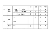
ここで、各走行モードにおけるクラッチC0とブレーキB0との係合および解放の状態と、各モータ・ジェネレータ2,3の動作の状態とを、図3に示す作動表を参照して説明する。図3で「EV」はエンジン1を停止させて走行するモードを示している。図3に示すようにシングルモータ走行モードによって駆動力を出力している場合あるいは制動力を作用させている場合には、クラッチC0とブレーキB0とが解放される。すなわち、変速部10がニュートラル状態にされて、エンジン1と動力分割機構5とのトルクの伝達が遮断される。その状態で、駆動力を駆動輪に伝達して走行する場合には、第2モータ・ジェネレータ3は力行制御され、制動力を作用させる場合には、第2モータ・ジェネレータ3が回生制御される。なお、図3には回生制御を「G」と示し、力行制御を「M」と示している。このようにクラッチC0とブレーキB0とを解放して、第2モータ・ジェネレータ3を力行制御することによりシングルモータ走行モードが設定される。
Here, the state of engagement and disengagement between the clutch C0 and the brake B0 and the state of operation of the motor generators 2 and 3 in each travel mode will be described with reference to the operation table shown in FIG. In FIG. 3, “EV” indicates a mode in which the vehicle travels with the engine 1 stopped. As shown in FIG. 3, when the driving force is output in the single motor traveling mode or when the braking force is applied, the clutch C0 and the brake B0 are released. That is, the
そのようにシングルモータ走行モードが設定されているときにおける変速部10の各回転要素および動力分割機構5の各回転要素の動作状態を図4に示している。図4に示す共線図は、左側が変速部10における各回転要素の動作状態を示し、右側が動力分割機構5における各回転要素の動作状態を示している。上述したようにクラッチC0とブレーキB0とが解放されていることにより変速部10がニュートラル状態となっている。また、変速部10の出力要素として機能するリングギヤ15が動力分割機構5におけるキャリヤ9に連結されているので、動力分割機構5から伝達された動力によって回転させられる。そして、エンジン1の慣性力(質量)やフリクショントルクが、サンギヤ16に連結された部材の慣性力(質量)よりも大きいので、エンジン1が停止してサンギヤ16が空転する。
FIG. 4 shows the operating states of the rotating elements of the
上記のように変速部10がニュートラル状態にされたときに駆動力を出力して走行する場合には、第2モータ・ジェネレータ3が力行制御されて、その第2モータ・ジェネレータ3から出力された動力によって走行する。この場合、第1モータ・ジェネレータ2は空転させていてもよく、所定の回転数に維持されるように回生制御され、あるいは第1モータ・ジェネレータ2が回転しないように電流を流して回転を止めるように制御(d軸ロック制御)していてもよい。なお、図4に示す例では、第1モータ・ジェネレータ2の回転が止められている。一方、制動力を作用させる場合には、第2モータ・ジェネレータ3を回生制御させる。そのように第2モータ・ジェネレータ3を回生制御して制動力を作用させる場合には、変速部10をニュートラル状態としてエンジン1と動力分割装置5とのトルクの伝達を遮断することにより、エンジン1のポンピングロスなどによる制動力が作用して回生することができるトルクが低下することを抑制もしくは防止することができる。その結果、シングルモータ走行モード時における回生効率を向上させることができる。さらに、第1モータ・ジェネレータ2の回転を止めることにより、第1モータ・ジェネレータ2の連れ回りによる動力損失を低減することができるので、回生効率を向上させることができる。なお、後進走行時には、第2モータ・ジェネレータ3の回転方向および出力トルクの方向が反転させられる。
As described above, when traveling with the driving force output when the
また、蓄電装置には充電量の上限があるので、その蓄電装置の充電量(State of Charge:SOC)が所定値以上のときには、シングルモータ走行モードで制動しているときであっても、過充電になることを防止するために、クラッチC0とブレーキB0とのいずれか一方が係合させられる。すなわち、エンジン1と動力分割機構5とがトルクを伝達することができるように連結されて、エンジンブレーキを作用させるように構成されている。なお、クラッチC0を係合させると変速部10は直結段になり、ブレーキB0を係合させたときよりも変速比が大きいので、要求される制動力が大きい場合には、クラッチC0が係合させられ、要求される制動力が小さい場合には、ブレーキB0が係合させられる。
In addition, since there is an upper limit of the charge amount of the power storage device, when the charge amount (State of Charge: SOC) of the power storage device is greater than or equal to a predetermined value, even when braking in the single motor travel mode, In order to prevent charging, either the clutch C0 or the brake B0 is engaged. That is, the engine 1 and the
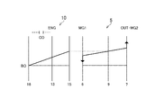
各モータ・ジェネレータ2,3が動力を出力して走行するツインモータ走行モードは、二つのモータ・ジェネレータ2,3から動力を出力することができるので、主にシングルモータ走行モードよりも要求される駆動力が大きいときに設定される。ツインモータ走行モードは、第1モータ・ジェネレータ2と第2モータ・ジェネレータ3とが力行制御される。そして、第1モータ・ジェネレータ2から出力された動力を駆動力として伝達するために、動力分割機構5におけるキャリヤ9の回転が止められる。具体的には、キャリヤ9に連結された変速部10の回転を止めるために、クラッチC0とブレーキB0とが係合させられる。このようにクラッチC0とブレーキB0とを係合させてキャリヤ9の回転が止められると、図5に示す共線図のように、第1モータ・ジェネレータ2から出力されたトルクと反対方向のトルクがリングギヤ7に伝達される。また、動力分割機構5におけるギヤ比に応じて減速して第1モータ・ジェネレータ2から出力されたトルクがリングギヤ7から出力される。なお、後進走行時には、それぞれのモータ・ジェネレータ2,3の回転方向およびトルクの出力方向を反転させればよい。また、制動時には、それぞれのモータ・ジェネレータ2,3のトルクの出力方向を反転させることにより、各モータ・ジェネレータ2,3によって回生することができる。
The twin motor travel mode in which each motor / generator 2 or 3 travels by outputting power can output power from the two motor / generators 2 and 3, and therefore is mainly required than the single motor travel mode. Set when the driving force is large. In the twin motor travel mode, the first motor / generator 2 and the second motor / generator 3 are power-running controlled. Then, in order to transmit the power output from the first motor / generator 2 as a driving force, the rotation of the
さらに、図2に示す動力伝達装置を有する車両では、主にエンジン1から出力された動力によって走行するエンジン走行モードを設定することができる。具体的には、要求駆動力に応じてクラッチC0またはブレーキB0を係合することにより、エンジン1と動力分割機構5とを連結することにより、エンジン1から出力された動力を駆動輪に伝達することができる。このようにエンジン1から出力された動力を駆動輪に伝達する過程で、第1モータ・ジェネレータ2から反力を動力分割機構5に作用させる。そのときに、第1モータ・ジェネレータ2が出力しているトルクの方向と、第1モータ・ジェネレータ2の回転方向が反対のときには、第1モータ・ジェネレータ2に伝達された動力によって発電される。すなわち、動力分割機構5にエンジン1から伝達された動力の一部を電力に変換する。そのように第1モータ・ジェネレータ2によって回生されて発電された電力、あるいは蓄電装置に充電された電力を第2モータ・ジェネレータ3に供給してカウンタドリブンギヤ12に伝達する。すなわち、第1モータ・ジェネレータ2を回生制御することにより、動力分割機構5におけるサンギヤ6を反力要素として機能させてエンジン1から出力された動力を伝達するとともに、第2モータ・ジェネレータ3によってトルクを加算するように制御される。したがってこの場合の制御は、ハイブリッド駆動制御と言い得る。なお、図3には、エンジン走行モードを「HV」と示している。
Further, in the vehicle having the power transmission device shown in FIG. 2, it is possible to set an engine travel mode in which the vehicle travels mainly by power output from the engine 1. Specifically, by engaging the clutch C0 or the brake B0 according to the required driving force, the engine 1 and the
また、第1モータ・ジェネレータ2は、通電される電流値やその周波数に応じて回転数を任意に制御することができる。そのため、第1モータ・ジェネレータ2の回転数を制御して、エンジン回転数を任意に制御することができる。具体的には、アクセル開度や車速などに応じてエンジン1の出力を定め、そのエンジン1の出力とエンジン1の燃費が良好になる最適燃費線とからエンジン1の運転点を定める。そして、第1モータ・ジェネレータ2の回転数を制御することで、エンジン回転数を燃費が良好となる最適燃費線上に制御することができる。すなわち、動力分割機構5は、電力によって制御可能な無段変速部として機能することができる。
Further, the first motor / generator 2 can arbitrarily control the rotation speed in accordance with the value of the current to be energized and its frequency. Therefore, the engine speed can be arbitrarily controlled by controlling the speed of the first motor / generator 2. Specifically, the output of the engine 1 is determined in accordance with the accelerator opening, the vehicle speed, and the like, and the operating point of the engine 1 is determined from the output of the engine 1 and the optimum fuel consumption line at which the fuel consumption of the engine 1 becomes good. Then, by controlling the rotation speed of the first motor / generator 2, the engine rotation speed can be controlled on the optimum fuel consumption line where the fuel consumption is good. That is, the
一方、車速が比較的高車速になったときに、エンジン回転数を上記のように制御すると、第1モータ・ジェネレータ2が力行制御される場合がある。そのため、第1モータ・ジェネレータ2が力行制御されることを抑制もしくは防止するために、比較的高車速になったときに、変速部10の変速比を増速段に変更するように構成されている。すなわち、低速あるいは中速走行時には、クラッチC0を係合して変速部10を直結段に設定し、高速走行時には、ブレーキB0を係合して増速段に設定するように構成されている。図6には、変速部10を増速段に設定したときにおける変速部10の各回転要素および動力分割機構5の各回転要素の動作状態を示している。なお、エンジン走行モードによって後進走行する場合には、変速部10が直結段となるようにクラッチC0が係合させられる。また、制動時には、要求される制動力に応じてクラッチC0とブレーキB0とのいずれか一方が係合させられて、エンジンブレーキを作用させる。
On the other hand, if the engine speed is controlled as described above when the vehicle speed becomes relatively high, the first motor / generator 2 may be subjected to power running control. Therefore, in order to suppress or prevent the first motor / generator 2 from being subjected to power running control, the gear ratio of the
つぎに、上記クラッチC0、ブレーキB0、各モータ・ジェネレータ、エンジン1を制御するための電子制御装置について説明する。図7にその電子制御装置のブロック図を示している。図7に示す電子制御装置は、走行のための全体的な制御を行うハイブリッド制御装置(HV−ECU)23と、各モータ・ジェネレータ2,3を制御するためのモータ・ジェネレータ制御装置(MG−ECU)24と、エンジン1を制御するためのエンジン制御装置(エンジン−ECU)25とが設けられている。これらの各制御装置23,24,25は、マイクロコンピュータを主体にして構成され、入力されたデータおよび予め記憶させられているデータを使用して演算を行い、その演算結果を制御指令信号として出力するように構成されている。その入力データの例を挙げると、ハイブリッド制御装置23には、車速、アクセル開度、第1モータ・ジェネレータ2の回転数、第2モータ・ジェネレータ3の回転数、前記リングギヤ7の回転数(出力軸回転数)、蓄電装置の充電容量(SOC)、図示しないマニュアルモードスイッチの出力信号、図示しないスポーツモードスイッチの出力信号、図示しないエンジンブレーキポジション(シフトレバー位置)の出力信号などがハイブリッド駆動装置23に入力されている。また、ハイブリッド駆動装置23から出力される指令信号の例を挙げると、第1モータ・ジェネレータ2のトルク指令値、第2モータ・ジェネレータ3のトルク指令値、エンジン1のトルク指令値、ならびにクラッチC0の制御油圧値(PC0)、ブレーキB0の制御油圧値(PB0)などがハイブリッド駆動装置23から出力されている。
Next, an electronic control unit for controlling the clutch C0, the brake B0, each motor / generator, and the engine 1 will be described. FIG. 7 shows a block diagram of the electronic control unit. The electronic control device shown in FIG. 7 includes a hybrid control device (HV-ECU) 23 that performs overall control for traveling, and a motor / generator control device (MG-) for controlling the motor / generators 2 and 3. ECU) 24 and an engine control device (engine-ECU) 25 for controlling the engine 1 are provided. Each of these
なお、マニュアルモードとは、運転者が任意に変速比を設定することができるモードであって、図示しないスイッチを運転者が操作することにより設定される。また、スポーツモードとは、加速性やステアリング特性などを変更して走行性能をスポーティーにするモードであって、図示しないスイッチを運転者が操作することによりが設定される。さらに、エンジンブレーキポジションとは、下り坂路などを走行しているときにエンジンブレーキを作用させるときに設定されるものであり、具体的には、シフトレバーの位置に応じた信号によって定められる。 The manual mode is a mode in which the driver can arbitrarily set the gear ratio, and is set by the driver operating a switch (not shown). The sport mode is a mode in which acceleration performance, steering characteristics, etc. are changed to make the running performance sporty, and is set when the driver operates a switch (not shown). Furthermore, the engine brake position is set when the engine brake is applied when traveling on a downhill road or the like, and is specifically determined by a signal corresponding to the position of the shift lever.
上記の第1モータ・ジェネレータ2のトルク指令値および第2モータ・ジェネレータ3のトルク指令値は、モータ・ジェネレータ制御装置24に制御データとして入力されており、モータ・ジェネレータ制御装置24はこれらのトルク指令値に基づいて演算を行って第1モータ・ジェネレータ2や第2モータ・ジェネレータ3の電流指令信号を出力するように構成されている。また、エンジントルク指令信号はエンジン制御装置25に制御データとして入力されており、エンジン制御装置25はそのエンジントルク指令信号に基づいて演算を行って電子スロットルバルブ(図示せず)に対してスロットル開度信号を出力し、また点火時期を制御する点火信号を出力するように構成されている。さらに、クラッチC0の制御油圧値(PC0)、ブレーキB0の制御油圧値(PB0)は、図示しない制御バルブなどに入力されるように構成されている。
The torque command value of the first motor / generator 2 and the torque command value of the second motor / generator 3 are input to the motor /
上述したエンジン1および第1モータ・ジェネレータ2ならびに第2モータ・ジェネレータ3の動力性能もしくは駆動特性は互いに異なっている。例えばエンジン1は低トルクかつ低回転数の領域から高トルクかつ高回転数の領域までの広い運転領域で運転でき、またエネルギ効率はトルクおよび回転数がある程度高い領域で良好になる。これに対してエンジン1の回転数やエンジン1を停止させる際のクランク角度などの制御および駆動力の出力を行う第1モータ・ジェネレータ2は、低回転数で大きいトルクを出力する特性を備え、前記ドライブシャフト4にトルクを出力する第2モータ・ジェネレータ3は、第1モータ・ジェネレータ2よりも高回転数で運転でき、かつ最大トルクが第1モータ・ジェネレータ2よりも小さい特性を備えている。そこで、この発明で対象とする動力伝達装置は、駆動力源を構成している上記のエンジン1や各モータ・ジェネレータ2,3を有効に利用して、エネルギ効率あるいは燃費が良好になるように制御される。すなわち、上記エンジン走行モードと、ツインモータ走行モードと、シングルモータ走行モードとを任意に変更して走行させるように制御される。 The power performance or drive characteristics of the engine 1, the first motor / generator 2, and the second motor / generator 3 described above are different from each other. For example, the engine 1 can be operated in a wide operating range from a low torque and low rotational speed region to a high torque and high rotational speed region, and energy efficiency is good in a region where torque and rotational speed are somewhat high. On the other hand, the first motor / generator 2 that controls the rotational speed of the engine 1 and the crank angle when the engine 1 is stopped and outputs the driving force has a characteristic of outputting a large torque at a low rotational speed, The second motor / generator 3 that outputs torque to the drive shaft 4 can be operated at a higher rotational speed than the first motor / generator 2 and has a characteristic that the maximum torque is smaller than that of the first motor / generator 2. . Therefore, the power transmission device targeted by the present invention effectively utilizes the engine 1 and the motor / generators 2 and 3 constituting the driving force source so that energy efficiency or fuel consumption is improved. Be controlled. That is, control is performed so that the engine travel mode, the twin motor travel mode, and the single motor travel mode are arbitrarily changed.
具体的には、アクセル開度がある程度以上に大きい場合、あるいは車速がある程度以上の高車速の場合には、エンジン走行モードが実行される。すなわち、アクセル開度や車速などに応じて、クラッチC0とブレーキB0とのいずれか一方を係合させて、エンジン1と動力伝達機構5とのトルクの伝達を可能にする。これに対して、アクセル開度が小さいことにより要求駆動力Fが小さい場合には、エンジン1が停止されるとともに、クラッチC0とブレーキB0とが解放されて、シングルモータ走行モードが実行される。また、要求駆動力Fが、第2モータ・ジェネレータ3のみから出力することができる駆動力よりも大きく、かつ各モータ・ジェネレータ2,3からトルクを出力することができる駆動力以下の場合には、エンジン1が停止させられるとともに、クラッチC0とブレーキB0とが係合させられて、ツインモータ走行モードが実行される。なお、シングルモータ走行モードもしくはツインモータ走行モードは、蓄電装置に充電量が十分にあること、第2モータ・ジェネレータ3がトルクを出力できる状態になっていること、エンジン1を停止してもよい状態になっていることなどの条件が成立している場合に実行される。
Specifically, when the accelerator opening is larger than a certain level, or when the vehicle speed is a high vehicle speed exceeding a certain level, the engine travel mode is executed. That is, according to the accelerator opening degree, the vehicle speed, etc., any one of the clutch C0 and the brake B0 is engaged, and torque transmission between the engine 1 and the
そして、車両が走行している場合、登降坂路などの道路状況や交通量あるいは規制速度の変化などの走行環境に応じてアクセル操作が行われ、また車速が変化するから、それに伴って走行モードが切り替えられる。例えば、シングルモータ走行モード時にアクセル開度が増大させられた場合には、ツインモータ走行モードあるいはエンジン走行モードに切り替えられ、エンジン走行モード時にアクセル開度が減じられた場合には、ツインモータ走行モードあるいはシングルモータ走行モードに切り替えられる。これらの走行モードの切り替えのための制御は、前述した電子制御装置によって実行される。 And when the vehicle is traveling, the accelerator operation is performed according to the road environment such as uphill / downhill road, the traffic volume or the travel environment such as the change in the regulation speed, and the vehicle speed changes accordingly. Can be switched. For example, when the accelerator opening is increased in the single motor driving mode, the mode is switched to the twin motor driving mode or the engine driving mode, and when the accelerator opening is decreased in the engine driving mode, the twin motor driving mode is switched. Alternatively, the mode is switched to the single motor travel mode. The control for switching these travel modes is executed by the electronic control device described above.
この発明に係る制御装置は、走行モードを切り替えるときに係合させられる係合装置の入力側回転部材の回転数と出力側回転部材の回転数との差を予めなくすことにより、走行モードの切り替えを行うときの制御応答性を向上させるように構成されている。その一例としては、エンジン1と駆動輪とのトルクの伝達を遮断して第2モータ・ジェネレータ3から動力を出力して走行しているシングルモータ走行モードから、エンジン1と駆動輪とのトルクの伝達を可能にして走行するエンジン走行モードに切り替えるときの制御応答性を向上させるように構成されている。 The control device according to the present invention eliminates the difference between the rotation speed of the input side rotation member and the rotation speed of the output side rotation member of the engagement device engaged when switching the travel mode, thereby switching the travel mode. It is configured to improve the control response when performing. As an example, torque transmission between the engine 1 and the drive wheels is stopped from a single motor running mode in which the transmission of torque between the engine 1 and the drive wheels is interrupted and power is output from the second motor / generator 3. It is configured to improve control responsiveness when switching to an engine running mode in which transmission is enabled.
図1は、その制御例を説明するためのフローチャートである。なお、図1に示すルーチンは、走行時に短時間毎に繰り返し実行されている。図1に示す制御例では、まず、モータ走行中か否かが判断される(ステップS1)。具体的には、シングルモータ走行モードが設定されて走行しているか否かが判断される。このステップS1は、ハイブリッド制御装置から出力される信号に基づいて判断することができ、具体的には、エンジン制御装置にエンジントルク指令値が出力されるか否かによって判断することができる。モータ走行中でなく、ステップS1で判断された場合にはリターンする。 FIG. 1 is a flowchart for explaining the control example. Note that the routine shown in FIG. 1 is repeatedly executed every short time during traveling. In the control example shown in FIG. 1, it is first determined whether or not the motor is running (step S1). Specifically, it is determined whether or not the vehicle is traveling with the single motor traveling mode set. This step S1 can be determined based on a signal output from the hybrid control device, and specifically can be determined based on whether or not an engine torque command value is output to the engine control device. If the motor is not running and it is determined in step S1, the process returns.
それとは反対に、モータ走行中でありステップS1で肯定的に判断された場合には、マニュアルモードスイッチがONされているか否かを判断する(ステップS2)。このステップS2は、エンジンブレーキを作用させるなどエンジン1と動力分割機構5とのトルクの伝達を可能にさせる可能性が高いか否かを判断するためである。マニュアルモードスイッチがONされている場合には、運転者によってダウンシフトする操作が行われてその変速比に応じた制動力を作用させるためにエンジン1と動力分割機構5とのトルクの伝達を可能にさせることとなる。そのため、マニュアルモータスイッチがONされている場合には、エンジン1と動力分割機構5とのトルクの伝達を可能にさせる可能性が高く、ステップS2で肯定的に判断される。なお、このステップS2の判断では、スポーツモードスイッチがONされているか否か、あるいはエンジンブレーキポジションが設定されているか否かによって判断することができる。要はモータ走行中から要求駆動力が増大してエンジン走行モードに切り替えられる可能性があるか否かを判断することができればよく、したがって、アクセル操作の変化率に応じて判断してもよい。
On the other hand, if the motor is running and a positive determination is made in step S1, it is determined whether or not the manual mode switch is turned on (step S2). This step S2 is for determining whether or not there is a high possibility of enabling torque transmission between the engine 1 and the
マニュアルモードスイッチがONされていることにより、ステップS2で肯定的に判断された場合には、第1モータ・ジェネレータ2の回転数が制御される(ステップS3)。このステップS3における制御は、動力分割機構5におけるキャリヤ9の回転数を予め定めた所定の回転数に制御するものであって、具体的には、キャリヤ9の回転数がほぼ「0」になるように制御される。このステップS3は、変速部10の各回転要素同士の回転数の差を低下させるためのステップである。具体的には、クラッチC0やブレーキB0の入力側回転部材(例えばキャリヤ13またはサンギヤ16)の回転数と出力側回転部材(例えばサンギヤ16)の回転数との差がほぼ「0」になるように制御する。なお、シングルモータ走行モード時には、クラッチC0およびブレーキB0が解放されて変速部10がニュートラル状態になっているので、第1モータ・ジェネレータ2の出力トルクは、駆動力として作用することがない。
If the determination in step S2 is affirmative because the manual mode switch is turned on, the rotational speed of the first motor / generator 2 is controlled (step S3). The control in step S3 controls the rotation speed of the
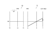
図8は、第2モータ・ジェネレータ3を回生制御して制動力を作用させているときに、第1モータ・ジェネレータ2の回転数を制御してキャリヤ9の回転数を「0」に制御した状態を示す共線図である。図8に示すように第1モータ・ジェネレータ2の回転数を制御してキャリヤ9の回転数が「0」になると、そのキャリヤ9に連結された変速部10におけるリングギヤ15の回転数が「0」になる。また、エンジン1が停止させられているので、エンジン1と連結されたキャリヤ13の回転数も「0」になる。その結果、クラッチC0とブレーキB0とが解放されている場合であっても、変速部10の各回転要素は、全て「0」になり、回転要素同士の回転数差、言い換えると、クラッチC0やブレーキB0の入力側回転部材の回転数と出力側回転部材の回転数とに差がなくなる。
FIG. 8 shows that when the second motor / generator 3 is regeneratively controlled to apply a braking force, the rotation speed of the
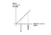
上記のようにステップS3で第1モータ・ジェネレータ2の回転数が制御されて、キャリヤ9の回転数がほぼ「0」になると、ついで、変速部10のスタンバイ制御が実行される(ステップS4)。具体的には、クラッチC0やブレーキB0の油圧をバッククリアランスが詰まるまで増大させる。言い換えると、クラッチC0やブレーキB0が係合してトルクを伝達する直前の油圧になるように、クラッチC0やブレーキB0の油圧が制御される。なお、このスタンバイ制御は、クラッチC0やブレーキB0に要求される油圧が、図9に示すようにそれらを係合させてトルクを伝達するときに要求される油圧よりも低いので、スタンバイ制御時における油圧の消費量を低下させることができる。すなわち、電動オイルポンプによって油圧を発生させている場合には、電動オイルポンプの回転数を低下させることができ、その結果、消費電力量を低下させることができる。そして、スタンバイ制御を実行した後は、リターンする。
As described above, when the rotational speed of the first motor / generator 2 is controlled in step S3 and the rotational speed of the
一方、マニュアルモードスイッチがOFFされていることにより、ステップS2で否定的に判断された場合には、エンジン1を始動させる可能性が高いか否かを判断する(ステップS5)。具体的には、蓄電装置の充電容量が低下した場合などにエンジン1を始動させる可能性が高いと判断される。エンジン1を始動させる可能性が高いときには、上記のようにエンジン1と動力分割機構5とのトルクの伝達を可能にさせる可能性が高くなる。そのため、エンジン1を始動させる可能性が高く、ステップS5で肯定的に判断された場合には、第1モータ・ジェネレータ2の回転数を制御した後に(ステップS3)、変速部10のスタンバイ制御を実行してリターンする。
On the other hand, if a negative determination is made in step S2 because the manual mode switch is turned off, it is determined whether or not the engine 1 is likely to be started (step S5). Specifically, it is determined that there is a high possibility that the engine 1 will be started when the charge capacity of the power storage device decreases. When the possibility of starting the engine 1 is high, there is a high possibility of enabling torque transmission between the engine 1 and the
それとは反対に、エンジン1を始動させる可能性が低く、ステップS6で否定的に判断された場合は、第1モータ・ジェネレータ2の回転数を任意に設定して(ステップS6)、リターンする。なお、シングルモータ走行モードで走行しているとき、より具体的には、第2モータ・ジェネレータ3の動力のみによって駆動力を出力しているときには、第1モータ・ジェネレータ2の連れ回りによる動力損失を低減するために、第1モータ・ジェネレータ2の回転数は「0」にすることが好ましい。 On the contrary, if the possibility of starting the engine 1 is low and a negative determination is made in step S6, the rotational speed of the first motor / generator 2 is arbitrarily set (step S6), and the process returns. When traveling in the single motor traveling mode, more specifically, when driving force is output only by the power of the second motor / generator 3, power loss due to the accompanying rotation of the first motor / generator 2. In order to reduce this, it is preferable to set the rotational speed of the first motor / generator 2 to “0”.
上述したようにモータ走行時であってエンジン1と動力分割機構5とのトルクの伝達を可能にする可能性が高い場合に、クラッチC0とブレーキB0とをスタンバイ制御することにより、モータ走行からエンジン走行させるときにクラッチC0やブレーキB0の油圧を単に増大させて係合させればよく、あるいはそのように係合させた後に第1モータ・ジェネレータ2によってエンジン1をクランキングさせればよい。そのため、クラッチC0やブレーキB0を同期させる分の時間を短くすることができ、その結果、走行モードを切り替えるときの制御応答性を向上させることができる。
As described above, when there is a high possibility that torque can be transmitted between the engine 1 and the
なお、上述した例では、シングルモータ走行モードからエンジン走行モードに切り替える可能性が高いときにスタンバイ制御を実行させる例を説明したが、シングルモータ走行モードからツインモータ走行モードに切り替える可能性が高い場合であっても同様の制御を実行することにより走行モードを切り替える制御の応答性を向上させることができる。具体的には、ツインモータ走行モードでは、クラッチC0とブレーキB0とを係合させることによって、第1モータ・ジェネレータ2の出力トルクを駆動力として伝達させるように構成されている。したがって、シングルモータ走行モードからツインモータ走行モードに切り替える場合には、クラッチC0とブレーキB0とを係合させることによって、ツインモータ走行モードに切り替えられる。そのため、シングルモータ走行モードからツインモータ走行モードに切り替える可能性が高いときに、クラッチC0およびブレーキB0の入力側回転部材の回転数と出力側回転部材の回転数との差をなくすように第1モータ・ジェネレータ2を制御することにより、走行モードを切り替えるときにおける制御応答性を向上させることができる。 In the above-described example, the standby control is executed when the possibility of switching from the single motor travel mode to the engine travel mode is high. However, when the possibility of switching from the single motor travel mode to the twin motor travel mode is high. Even so, it is possible to improve the responsiveness of the control for switching the traveling mode by executing the same control. More specifically, in the twin motor travel mode, the output torque of the first motor / generator 2 is transmitted as a driving force by engaging the clutch C0 and the brake B0. Therefore, when switching from the single motor travel mode to the twin motor travel mode, the clutch is switched to the twin motor travel mode by engaging the clutch C0 and the brake B0. Therefore, when there is a high possibility of switching from the single motor travel mode to the twin motor travel mode, the first difference is made so as to eliminate the difference between the rotation speed of the input side rotation member and the rotation speed of the output side rotation member of the clutch C0 and the brake B0. By controlling the motor / generator 2, it is possible to improve control responsiveness when the traveling mode is switched.
また、上述した例では、エンジン1と動力分割機構5との間にクラッチC0とブレーキB0とのいずれか一方を係合させることによりエンジン1と動力分割機構5との動力の伝達を可能にする変速部10を備えた例を挙げて説明したが、エンジン1と動力分割機構5との間にクラッチを設け、あるいはそのクラッチに加えて出力軸14の回転を止めるブレーキを設けた動力伝達装置であってもよい。
In the above-described example, the power transmission between the engine 1 and the
さらに、動力分割機構や変速部は、ダブルピニオン型の遊星歯車機構によって構成されていてもよい。そして、クラッチやブレーキは、油圧によって制御されるものに限らず、電磁力などによって係合および解放が制御されるように構成されたものであってもよく、また、噛み合いクラッチなど摩擦力以外の力によってトルクを伝達するように構成されたものであってもよい。 Further, the power split mechanism and the transmission unit may be configured by a double pinion type planetary gear mechanism. The clutch and brake are not limited to those controlled by hydraulic pressure, but may be configured such that engagement and release are controlled by electromagnetic force or the like, and other than frictional force such as a meshing clutch. It may be configured to transmit torque by force.
1…エンジン、 2…第1モータ・ジェネレータ、 3…第2モータ・ジェネレータ、 4…ドライブシャフト、 5…動力分割機構、 6,16…サンギヤ、 7,15,22…リングギヤ、 8,12…ピニオンギヤ、 9,13…キャリヤ、 10…変速部、 11…ドライブギヤ、 13…出力軸、 17…カウンタシャフト、 18…カウンタドリブンギヤ、 19…リダクションギヤ、 20…カウンタドライブギヤ、 21…デファレンシャルギヤ。
DESCRIPTION OF SYMBOLS 1 ... Engine, 2 ... 1st motor generator, 3 ... 2nd motor generator, 4 ... Drive shaft, 5 ... Power split mechanism, 6, 16 ... Sun gear, 7, 15, 22 ... Ring gear, 8, 12 ...
Claims (1)
前記第1係合装置および前記第2係合装置のそれぞれは、入力側回転部材と出力側回転部材とを備えるとともに、油圧によって係合するように構成され、
前記エンジンを停止しかつ前記第1係合装置および前記第2係合装置を解放した前記第2モータの駆動力で走行する前記第3走行モードの状態で前記エンジンを始動する可能性が高いことを判断し、
前記エンジンを始動する可能性が高いことの判断が成立した場合に、前記第1係合装置または前記第2係合装置の少なくともいずれか一方の係合装置における前記入力側回転部材と前記出力側回転部材との回転数差が低減するように前記第1モータの回転数を制御し、
ついで前記第1係合装置または前記第2係合装置の少なくともいずれか一方の係合装置の油圧を、トルクを伝達する直前の油圧に設定するスタンバイ制御を実行するように構成されていることを特徴とするハイブリッド車両の制御装置。 A power split mechanism having a differential action having a first rotating element connected to an engine, a second rotating element connected to a first motor, and a third rotating element connected to an output shaft, and the output shaft And a second motor configured to transmit torque to the first engagement device for enabling transmission of power between the engine and the first rotating element by engaging with the second motor and setting the first traveling mode; And a second engagement device configured to stop the rotation of the first rotation element and set the second traveling mode by engaging with each other, and the first traveling mode or the second traveling. From the mode, the first engagement device and the second engagement device are released to switch to a third traveling mode in which power is output from the second motor and torque is transmitted to the output shaft. The control apparatus of the hybrid vehicle has,
Each of the first engagement device and the second engagement device includes an input side rotation member and an output side rotation member, and is configured to be engaged by hydraulic pressure,
There is a high possibility that the engine is started in the state of the third travel mode in which the engine travels with the driving force of the second motor that stops the engine and releases the first engagement device and the second engagement device. Judging
When it is determined that the engine is highly likely to be started, the input side rotation member and the output side in at least one of the first engagement device and the second engagement device Controlling the rotational speed of the first motor so as to reduce the rotational speed difference with the rotating member;
Then the hydraulic pressure of at least one of the engagement device of the first engagement device or the second engagement device, has been configured to run a standby control to set the hydraulic pressure immediately before transmitting a torque A hybrid vehicle control device.
Priority Applications (1)
| Application Number | Priority Date | Filing Date | Title |
|---|---|---|---|
| JP2013145292A JP6070451B2 (en) | 2013-07-11 | 2013-07-11 | Control device for hybrid vehicle |
Applications Claiming Priority (1)
| Application Number | Priority Date | Filing Date | Title |
|---|---|---|---|
| JP2013145292A JP6070451B2 (en) | 2013-07-11 | 2013-07-11 | Control device for hybrid vehicle |
Publications (2)
| Publication Number | Publication Date |
|---|---|
| JP2015016782A JP2015016782A (en) | 2015-01-29 |
| JP6070451B2 true JP6070451B2 (en) | 2017-02-01 |
Family
ID=52438227
Family Applications (1)
| Application Number | Title | Priority Date | Filing Date |
|---|---|---|---|
| JP2013145292A Active JP6070451B2 (en) | 2013-07-11 | 2013-07-11 | Control device for hybrid vehicle |
Country Status (1)
| Country | Link |
|---|---|
| JP (1) | JP6070451B2 (en) |
Families Citing this family (6)
| Publication number | Priority date | Publication date | Assignee | Title |
|---|---|---|---|---|
| JP6394654B2 (en) | 2016-07-19 | 2018-09-26 | トヨタ自動車株式会社 | vehicle |
| JP6897512B2 (en) * | 2017-11-13 | 2021-06-30 | トヨタ自動車株式会社 | Hybrid vehicle driving force control device |
| JP2019157822A (en) | 2018-03-16 | 2019-09-19 | トヨタ自動車株式会社 | Turbocharger |
| JP7215967B2 (en) * | 2019-06-18 | 2023-01-31 | トヨタ自動車株式会社 | Hybrid vehicle control device |
| JP7414468B2 (en) | 2019-10-24 | 2024-01-16 | 株式会社Subaru | vehicle |
| JP7414467B2 (en) | 2019-10-24 | 2024-01-16 | 株式会社Subaru | vehicle |
Family Cites Families (4)
| Publication number | Priority date | Publication date | Assignee | Title |
|---|---|---|---|---|
| JP2009006781A (en) * | 2007-06-27 | 2009-01-15 | Nissan Motor Co Ltd | Vehicular control apparatus |
| JP2012071693A (en) * | 2010-09-29 | 2012-04-12 | Toyota Motor Corp | Hybrid vehicle drive control device |
| JP2012224238A (en) * | 2011-04-20 | 2012-11-15 | Aisin Aw Co Ltd | Control device of hybrid vehicle |
| JP5141802B2 (en) * | 2011-07-19 | 2013-02-13 | トヨタ自動車株式会社 | Hybrid drive device |
-
2013
- 2013-07-11 JP JP2013145292A patent/JP6070451B2/en active Active
Also Published As
| Publication number | Publication date |
|---|---|
| JP2015016782A (en) | 2015-01-29 |
Similar Documents
| Publication | Publication Date | Title |
|---|---|---|
| JP6213494B2 (en) | Hybrid vehicle | |
| JP4215092B2 (en) | Engine starter for hybrid vehicle | |
| US9815454B2 (en) | Control system for hybrid vehicle | |
| JP5884897B2 (en) | Drive control apparatus for hybrid vehicle | |
| JP6070451B2 (en) | Control device for hybrid vehicle | |
| US9682697B2 (en) | Control system for hybrid vehicle | |
| JP6327238B2 (en) | Drive control apparatus for hybrid vehicle | |
| JP5907155B2 (en) | Control device for hybrid drive | |
| JP2008120233A (en) | Hybrid driving device | |
| WO2010106824A1 (en) | Control apparatus for power transmission device | |
| CN113753020B (en) | Control device for hybrid vehicle | |
| US9771065B2 (en) | Vehicle control system | |
| JP6252616B2 (en) | Engine start control device for hybrid vehicle | |
| JP6414025B2 (en) | Hybrid vehicle driving force control device | |
| WO2015008396A1 (en) | Control device for hybrid vehicle | |
| WO2015004818A1 (en) | Hybrid vehicle control device | |
| JP2008120139A (en) | Hybrid drive system | |
| JP2018103846A (en) | Control system for hybrid vehicle | |
| CN112092799A (en) | Control device for hybrid vehicle | |
| JP2015020665A (en) | Control device of vehicle | |
| JP2009154808A (en) | Vehicle drive device | |
| JP6424808B2 (en) | Driving force control device for hybrid vehicle | |
| JP6146273B2 (en) | Power transmission control device | |
| JP2017087808A (en) | Hybrid-vehicular drive control apparatus | |
| JP2017185941A (en) | Hybrid-vehicular drive control apparatus |
Legal Events
| Date | Code | Title | Description |
|---|---|---|---|
| A621 | Written request for application examination |
Free format text: JAPANESE INTERMEDIATE CODE: A621 Effective date: 20150806 |
|
| A977 | Report on retrieval |
Free format text: JAPANESE INTERMEDIATE CODE: A971007 Effective date: 20160527 |
|
| A131 | Notification of reasons for refusal |
Free format text: JAPANESE INTERMEDIATE CODE: A131 Effective date: 20160607 |
|
| A521 | Written amendment |
Free format text: JAPANESE INTERMEDIATE CODE: A523 Effective date: 20160715 |
|
| TRDD | Decision of grant or rejection written | ||
| A01 | Written decision to grant a patent or to grant a registration (utility model) |
Free format text: JAPANESE INTERMEDIATE CODE: A01 Effective date: 20161206 |
|
| A61 | First payment of annual fees (during grant procedure) |
Free format text: JAPANESE INTERMEDIATE CODE: A61 Effective date: 20161219 |
|
| R151 | Written notification of patent or utility model registration |
Ref document number: 6070451 Country of ref document: JP Free format text: JAPANESE INTERMEDIATE CODE: R151 |