JP6065262B2 - Power supply - Google Patents
Power supply Download PDFInfo
- Publication number
- JP6065262B2 JP6065262B2 JP2012226964A JP2012226964A JP6065262B2 JP 6065262 B2 JP6065262 B2 JP 6065262B2 JP 2012226964 A JP2012226964 A JP 2012226964A JP 2012226964 A JP2012226964 A JP 2012226964A JP 6065262 B2 JP6065262 B2 JP 6065262B2
- Authority
- JP
- Japan
- Prior art keywords
- voltage
- power supply
- diode
- supply device
- mosfets
- Prior art date
- Legal status (The legal status is an assumption and is not a legal conclusion. Google has not performed a legal analysis and makes no representation as to the accuracy of the status listed.)
- Expired - Fee Related
Links
Images


Classifications
-
- H—ELECTRICITY
- H02—GENERATION; CONVERSION OR DISTRIBUTION OF ELECTRIC POWER
- H02M—APPARATUS FOR CONVERSION BETWEEN AC AND AC, BETWEEN AC AND DC, OR BETWEEN DC AND DC, AND FOR USE WITH MAINS OR SIMILAR POWER SUPPLY SYSTEMS; CONVERSION OF DC OR AC INPUT POWER INTO SURGE OUTPUT POWER; CONTROL OR REGULATION THEREOF
- H02M3/00—Conversion of dc power input into dc power output
- H02M3/02—Conversion of dc power input into dc power output without intermediate conversion into ac
- H02M3/04—Conversion of dc power input into dc power output without intermediate conversion into ac by static converters
- H02M3/10—Conversion of dc power input into dc power output without intermediate conversion into ac by static converters using discharge tubes with control electrode or semiconductor devices with control electrode
- H02M3/145—Conversion of dc power input into dc power output without intermediate conversion into ac by static converters using discharge tubes with control electrode or semiconductor devices with control electrode using devices of a triode or transistor type requiring continuous application of a control signal
- H02M3/155—Conversion of dc power input into dc power output without intermediate conversion into ac by static converters using discharge tubes with control electrode or semiconductor devices with control electrode using devices of a triode or transistor type requiring continuous application of a control signal using semiconductor devices only
- H02M3/156—Conversion of dc power input into dc power output without intermediate conversion into ac by static converters using discharge tubes with control electrode or semiconductor devices with control electrode using devices of a triode or transistor type requiring continuous application of a control signal using semiconductor devices only with automatic control of output voltage or current, e.g. switching regulators
- H02M3/158—Conversion of dc power input into dc power output without intermediate conversion into ac by static converters using discharge tubes with control electrode or semiconductor devices with control electrode using devices of a triode or transistor type requiring continuous application of a control signal using semiconductor devices only with automatic control of output voltage or current, e.g. switching regulators including plural semiconductor devices as final control devices for a single load
-
- H—ELECTRICITY
- H02—GENERATION; CONVERSION OR DISTRIBUTION OF ELECTRIC POWER
- H02M—APPARATUS FOR CONVERSION BETWEEN AC AND AC, BETWEEN AC AND DC, OR BETWEEN DC AND DC, AND FOR USE WITH MAINS OR SIMILAR POWER SUPPLY SYSTEMS; CONVERSION OF DC OR AC INPUT POWER INTO SURGE OUTPUT POWER; CONTROL OR REGULATION THEREOF
- H02M3/00—Conversion of dc power input into dc power output
- H02M3/22—Conversion of dc power input into dc power output with intermediate conversion into ac
- H02M3/24—Conversion of dc power input into dc power output with intermediate conversion into ac by static converters
- H02M3/28—Conversion of dc power input into dc power output with intermediate conversion into ac by static converters using discharge tubes with control electrode or semiconductor devices with control electrode to produce the intermediate ac
- H02M3/325—Conversion of dc power input into dc power output with intermediate conversion into ac by static converters using discharge tubes with control electrode or semiconductor devices with control electrode to produce the intermediate ac using devices of a triode or a transistor type requiring continuous application of a control signal
- H02M3/335—Conversion of dc power input into dc power output with intermediate conversion into ac by static converters using discharge tubes with control electrode or semiconductor devices with control electrode to produce the intermediate ac using devices of a triode or a transistor type requiring continuous application of a control signal using semiconductor devices only
- H02M3/33569—Conversion of dc power input into dc power output with intermediate conversion into ac by static converters using discharge tubes with control electrode or semiconductor devices with control electrode to produce the intermediate ac using devices of a triode or a transistor type requiring continuous application of a control signal using semiconductor devices only having several active switching elements
- H02M3/33573—Full-bridge at primary side of an isolation transformer
-
- H—ELECTRICITY
- H02—GENERATION; CONVERSION OR DISTRIBUTION OF ELECTRIC POWER
- H02M—APPARATUS FOR CONVERSION BETWEEN AC AND AC, BETWEEN AC AND DC, OR BETWEEN DC AND DC, AND FOR USE WITH MAINS OR SIMILAR POWER SUPPLY SYSTEMS; CONVERSION OF DC OR AC INPUT POWER INTO SURGE OUTPUT POWER; CONTROL OR REGULATION THEREOF
- H02M1/00—Details of apparatus for conversion
- H02M1/0067—Converter structures employing plural converter units, other than for parallel operation of the units on a single load
- H02M1/007—Plural converter units in cascade
Description
本発明は、交流電源電圧の瞬時低下補償機能を有する電源装置に関し、詳しくは、装置を高効率化、小形化するための技術に関するものである。 The present invention relates to a power supply apparatus having an instantaneous power supply voltage instantaneous drop compensation function, and more particularly to a technique for improving the efficiency and miniaturization of the apparatus.
図3は、交流電源電圧の瞬時低下補償機能を有する電源装置の第1の従来技術を示している。
図3において、1は交流電源であり、その両端にはダイオード2〜5からなる整流回路が接続されている。ダイオード4,5の直列回路の両端には、リアクトル6とMOSFET等の半導体スイッチング素子7とが直列に接続され、スイッチング素子7の両端には、ダイオード8と平滑コンデンサ9とが直列に接続されている。
FIG. 3 shows a first prior art of a power supply device having a function of compensating for an instantaneous decrease in AC power supply voltage.
In FIG. 3,
平滑コンデンサ9の両端には、半導体スイッチング素子10〜13からなるインバータINVの直流入力端子が接続され、インバータINVの交流出力端子には、変圧器14の一次巻線14aが接続されている。
変圧器14の二次巻線14bの両端には、ダイオード15〜18からなる整流回路が接続されている。ダイオード17,18の直列回路の両端には、リアクトル19とコンデンサ20とが直列に接続され、コンデンサ20の両端には、負荷21が接続されている。
Both ends of the smoothing capacitor 9 are connected to a DC input terminal of an inverter INV composed of
A rectifier circuit composed of
上述した電源装置に求められる機能は、以下の通りである。
・交流入力電圧を、所望の大きさの直流電圧に変換し、かつ、入力電圧や負荷電流の変動に関わらず出力電圧を一定に保つ。
・交流入力部と直流出力部とを絶縁する。
・交流入力電流を、力率がほぼ1の正弦波とする。
更に、負荷21が情報・通信機器のように信頼性を要求されるものである場合には、交流電源1の数[ms]〜数サイクル程度の期間の電圧低下、いわゆる瞬時電圧低下(以下、瞬低という)が発生した際にも一定の出力電圧を確保できる機能(以下、この機能を瞬低補償機能という)を有することが要求される。
The functions required for the power supply apparatus described above are as follows.
・ Converts AC input voltage to DC voltage of desired magnitude, and keeps output voltage constant regardless of fluctuations in input voltage and load current.
• Insulate the AC input section from the DC output section.
• The AC input current is a sine wave with a power factor of approximately 1.
Furthermore, when the
これらの機能を実現するための動作について、図4を参照しつつ説明する。
図4(a)において、交流電源1からの入力電圧Vinは正弦波状の波形であり、ダイオード2〜5からなる整流回路の出力電圧(整流電圧)は、図4(b)のVr1に示す波形となる。ここで、例えばVinが正極性の場合、図3のスイッチング素子7をオンすると、交流電源1→ダイオード2→リアクトル6→スイッチング素子7→ダイオード5→交流電源1の経路で電流が流れ、整流電圧Vr1がリアクトル6の両端に印加されて電流ILが増加する。
An operation for realizing these functions will be described with reference to FIG.
4 (a), the input voltage V in from the
また、スイッチング素子7をオフすると、交流電源1→ダイオード2→リアクトル6→ダイオード8→平滑コンデンサ9→ダイオード5→交流電源1の経路で電流ILが流れる。このとき、リアクトル6には平滑コンデンサ9の電圧Ed1と入力電圧Vinとの差電圧が印加されるが、回路の動作により、Ed1はVinのピーク値よりも高く保たれているので、電流ILは減少する。
When the switching element 7 is turned off, the current IL flows through the path of the
上述したスイッチング素子7のオンとオフとの時比率を制御することにより、電流ILの波形及び振幅を任意に制御することができる。この電流ILの波形を図4(b)のような正弦波整流波形(簡単化のためリプル分は無視している)とすれば、図4(a)に示すように入力電流Iinは正弦波状の波形となる。また、負荷電力に応じてILの振幅を制御することで、平滑コンデンサ9の電圧Ed1を一定に保ち、ひいてはインバータINVの出力電圧を一定に保つことができる。 By controlling the time ratio of the on and off switching element 7 described above, it is possible to arbitrarily control the waveform and amplitude of the current I L. If a sine-wave rectified waveform as shown in FIG. 4 the waveform of the current I L (b) (ripple component for simplicity is neglected), the input current I in, as shown in FIG. 4 (a) It becomes a sine wave waveform. Further, by controlling the amplitude of I L in accordance with the load power, keeping the voltage E d1 of the smoothing capacitor 9 constant, it is possible to maintain the output voltage of the inverter INV constant turn.
ここで、図4(c),(d),(e)は、瞬低補償機能がある場合とない場合のスイッチング素子10〜13の動作及び各部の電圧波形を示したものである。
スイッチング素子10〜13からなるインバータINVは、平滑コンデンサ9の電圧Ed1を高周波の交流電圧に変換する。図4(c),(d)に示すように、スイッチング素子10,13をオンすると変圧器14の一次巻線14aに正の電圧Vtが印加され、スイッチング素子11,12をオンすると一次巻線14aに負の電圧Vtが印加される。このように一次巻線14aに正負の電圧Vtを交互に印加することにより変圧器14に高周波交流電圧Vtを入力する(図4では、見易さの都合上、Vin,Vtの周期を同程度に表現しているが、一般的にはVinが50または60[Hz]の商用周波数であるのに対し、Vtは変圧器を小形化するために数[kHz]以上とする)。
Here, FIGS. 4C, 4D, and 4E show the operation of the
The inverter INV composed of the
変圧器14は、入力された高周波交流電圧Vtを絶縁して変圧し、その二次巻線14bの両端電圧をダイオード15〜18からなる整流回路により図4(e)の整流電圧Vr2に変換した後、リアクトル19及びコンデンサ20により平滑し、出力電圧Voutとして負荷21に印加する。この出力電圧Voutは、スイッチング素子10,13またはスイッチング素子11,12をオンする時比率(以下、インバータ時比率という)によって制御することができる。
電源装置が瞬低補償機能を備えており、交流電源1が健全である場合の動作は、図4(c),(d),(e)において[通常時]として示す通りである。
これに対し、[瞬低時]では、交流電源1の瞬低発生により入力電力が減少して電圧Ed1が低下し、電圧Vtの振幅も減少する。しかし、電圧Ed1の低下が所定範囲内であれば、スイッチング素子10,13またはスイッチング素子11,12をオンする時比率を大きくすることによって電圧Vtの平均値を一定に保ち、所定の整流電圧Vr2ひいては出力電圧Voutを維持することができる。
The operation in the case where the power supply device has a voltage sag compensation function and the
On the other hand, in the “instantaneous voltage drop”, the input power is reduced by the occurrence of the voltage drop of the
しかしながら、瞬低補償機能を持たせると、装置の効率が低下する。これは以下の理由による。
電圧Ed1がある程度低下した場合でも一定の出力電圧Voutを維持するためには、変圧器14の変圧比(一次巻線14aと二次巻線14bとの巻数比であるn:1のnの値)を、本来の最適値より小さくする必要がある。例えば、通常時に電圧Ed1が400[V]で一定に保たれており、出力電圧Voutが10[V]であるならば、インバータINVを最大時比率で運転するために必要な変圧器14の変圧比は400:10、すなわちn=40となる(簡単化のため、ここでは回路内の電圧降下を無視する)。
However, the provision of the voltage sag compensation function reduces the efficiency of the device. This is due to the following reason.
In order to maintain a constant output voltage V out even when the voltage E d1 is lowered to some extent, the transformer ratio of the transformer 14 (n: 1 of n: 1, which is the turn ratio of the
一方、電圧Ed1が200[V]まで低下しても出力電圧Voutを10[V]のまま維持するために必要な変圧比は200:10、すなわちn=20となる。この条件で変圧比nを設定すると、電圧Ed1が400[V]である通常時は、Voutを10[V]に保つためにインバータ時比率をおよそ0.5にして運転することになる。
この場合、変圧器14の一次側に流れる電流の振幅はリアクトル19を流れる電流の1/nであるが、瞬低補償機能を有する場合には本来の最適値が40である変圧比nが20になり、瞬低補償機能を持たせることによって変圧器14の一次側に流れる電流値が大きくなる。このため、スイッチング素子10〜13及び一次巻線14aで発生する損失が大きくなる。
On the other hand, even if the voltage E d1 decreases to 200 [V], the transformation ratio necessary to maintain the output voltage V out at 10 [V] is 200: 10, that is, n = 20. When the transformation ratio n is set under this condition, in the normal time when the voltage E d1 is 400 [V], the inverter is operated with an inverter time ratio of about 0.5 in order to keep Vout at 10 [V]. .
In this case, the amplitude of the current flowing through the primary side of the
整流電圧Vr2はおよそEd1/nであるが、変圧比nが小さくなると通常時にダイオード15〜18に印加される電圧が大きくなるので、これらのダイオード15〜18には耐圧の高い部品を用いる必要がある。一般に、半導体部品は耐圧が高いほど同一条件での損失は大きくなる傾向があるため、装置内で発生する損失が大きくなる。
The rectified voltage V r2 is approximately E d1 / n, but when the transformation ratio n is reduced, the voltage applied to the
また、[瞬低補償機能あり]の場合の[通常時]では、電圧Vr2が印加されない期間が長くなるので、電圧Vr2を平滑するために必要なリアクトル19のインダクタンス値が大きくなる。図4(d),(e)の[瞬低補償機能なし]の場合、整流電圧Vr2が所定値から0[V]に低下するまでの期間は電圧Vtの極性が切り替わる僅かな時間であるが、[瞬低補償機能あり]の場合の[通常時]には一周期の1/2の期間は整流電圧Vr2が印加されず、この期間はリアクトル19によって負荷21にエネルギーを供給する必要がある。
これらに起因してリアクトル19が大形化することになり、結果として、装置全体の大形化やリアクトル19の発生損失の増大を招く。
Further, in the “normal time” in the case of “with instantaneous drop compensation function”, the period during which the voltage V r2 is not applied becomes long, so that the inductance value of the
As a result, the
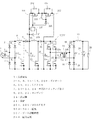
さて、上述したようなインバータINV以降の損失増加を回避する第2の従来技術として、図5に示す回路が知られている。
図5において、平滑コンデンサ9とインバータINVとの間の正側直流母線には、リアクトル22とダイオード24とが直列に接続されていると共に、リアクトル22とダイオード24との接続点と負側直流母線との間には、半導体スイッチング素子23が接続されている。また、ダイオード24のカソードと負側直流母線との間には、平滑コンデンサ25が接続されている。これらのリアクトル22、ダイオード24、スイッチチング素子23及び平滑コンデンサ25により、昇圧チョッパが構成されている。なお、図5における他の構成は図3と同様であるため、説明を省略する。
Now, a circuit shown in FIG. 5 is known as a second conventional technique for avoiding an increase in loss after the inverter INV as described above.
In FIG. 5, a
上記昇圧チョッパにより、リアクトル6、スイッチング素子7及びダイオード8からなる回路と同様の動作によってリアクトル22を流れる電流を制御することができ、結果として入力電圧Ed1よりも高い出力電圧Ed2を得ることができる。すなわち、昇圧チョッパの動作により、瞬低時にコンデンサ9の電圧Ed1が低下(例えば400[V]から200[V])してもコンデンサ25の電圧Ed2を一定(例えば400[V])に保つことができ、前述した例では変圧比をn=40とする設計が可能となる。
なお、特許文献1の第2図には、上述した昇圧チョッパを用いて交流電源電圧の低下を補償する回路が示されている。
The step-up chopper can control the current flowing through the
FIG. 2 of
しかしながら、図5に示した回路には以下の欠点がある。
すなわち、昇圧チョッパを構成するリアクトル22、スイッチング素子23及びダイオード24が、損失を発生する。スイッチング素子23がオン/オフ動作している場合はもちろん、電圧Ed1が十分高く、スイッチング素子23が停止している場合においても、リアクトル22の巻線抵抗やダイオード24の順電圧降下により、損失を生じる。この損失により、インバータINV以降の回路損失を低減させた分が相殺されてしまう。
また、リアクトル22には電流が常時流れるため、昇圧動作する時間が極めて短いにも関わらず、電流容量の大きなリアクトル22が必要となる。
However, the circuit shown in FIG. 5 has the following drawbacks.
That is, the
In addition, since a current always flows through the
更に、インバータINVから発生するリプル電流を吸収するため、大容量の平滑コンデンサ25が必要となる。一方の平滑コンデンサ9は、瞬低時のエネルギーを供給するために容量を十分大きくしてあるので、図3の回路では、この平滑コンデンサ9が、リアクトル6、スイッチング素子7及びダイオード8からなる回路によって発生するリプル電流、及び、インバータINVのリプル電流の両方を吸収する役割を担うことができる。
しかし、図5の回路ではインバータINVと平滑コンデンサ9との間にリアクトル22が挿入されるので、高周波リプル電流が通過できない。このため、別途、平滑コンデンサ25が必要となり、これによって装置が大形化する。
Furthermore, a large-
However, in the circuit of FIG. 5, the
なお、特許文献2には、予め充電しておいた別のコンデンサにより瞬低時のエネルギーを供給する回路が示されている。しかしながら、この特許文献2に開示されている回路でも、通常時にリプルを吸収するコンデンサと瞬低時にエネルギーを供給するコンデンサとが分離されているため、装置の大形化を避けられない。
上述した装置の大形化を回避する第3の従来技術として、図6に示す回路が知られている。
図6において、101はダイオード8,24のカソード間に接続されたバイパス用のダイオードであり、その他の構成は図5と同様である。交流電源1が健全である通常時にはスイッチング素子23は動作せず、リアクトル22、スイッチング素子23、ダイオード24及びコンデンサ25からなる昇圧チョッパはダイオード101によりバイパスされる。ここで、電圧Ed1,Ed2は、通常時、瞬低時の何れも平滑された直流電圧であるので、ダイオード24と異なり、ダイオード101には高周波を整流する性能は不要であり、低速のダイオードを用いることができる。低速のダイオードの順電圧は高速のものに比べて1/2程度であり、また、通常時はリアクトル22に電流が流れないため、図5の回路に比べて損失を大幅に低減することができる。
A circuit shown in FIG. 6 is known as a third conventional technique for avoiding the increase in size of the apparatus described above.
In FIG. 6,
更に、リアクトル22に通電する時間は瞬低時の数10[ms]以下であるため、リアクトル22には巻線を細くした短時間定格のものを用いることができ、図5の回路に比べてリアクトル22の大幅な小形化が可能である。また、ダイオード101によるバイパス動作により平滑コンデンサ9とインバータINVとの間にリアクトルが介在しなくなるので、通常時、平滑コンデンサ9はインバータINVのリプル電流も担うことができる。このため、平滑コンデンサ25は瞬低期間中の昇圧チョッパ及びインバータINVのリプルにのみ耐えれば良く、極めて小容量のものを用いることができるようになる。
この方法は、例えば特許文献3に示されている。
Furthermore, since the time for energizing the
This method is disclosed in
一方、近年、地球環境問題などを背景として、電源装置にも更なる高効率化が求められている。このため、徹底的な損失の低減が必要とされており、バイパスダイオード101によって発生する損失をも低減する必要が新たに生じている。
従来より、ダイオードが発生する損失を低減する手法としては、一般に同期整流と呼ばれる方法が知られており、この同期整流は、ダイオードをMOSFETに置き換えるものである。MOSFETはゲートに電圧を与えれば順方向すなわちドレインからソースへ電流を流せるだけではなく、逆方向すなわちソースからドレインへと電流を流せることが知られている。導通状態のMOSFETは、抵抗性すなわち電圧降下が電流に比例する性質を持つため、電流容量に対して導通電流の小さい範囲では電圧降下がダイオードより小さくなる。これを利用して、図6のダイオード101をMOSFETに置き換え、その並列数または電流容量を大きく、すなわち導通時の抵抗値(以下、オン抵抗と呼ぶ)を小さくすれば、損失を抑制することができる。
しかしながら、既にダイオード101の電圧降下は1[V]以下程度であり、これに対して十分に電圧降下を小さくする効果を得るには、例えばスイッチング素子7と同じ耐圧、仕様のMOSFETを用いた場合、並列数をスイッチング素子7の数個分にする必要があり、装置コストの上昇を招く。
On the other hand, in recent years, power supply devices have been required to have higher efficiency against the background of global environmental problems. For this reason, it is necessary to thoroughly reduce the loss, and a new need arises to reduce the loss generated by the
Conventionally, as a technique for reducing a loss generated by a diode, a method generally called synchronous rectification is known, and this synchronous rectification replaces the diode with a MOSFET. It is known that MOSFETs can not only flow current in the forward direction, that is, from the drain to the source, but also flow current in the reverse direction, that is, from the source to the drain if a voltage is applied to the gate. Since the MOSFET in the conductive state has resistance, that is, the voltage drop is proportional to the current, the voltage drop is smaller than that of the diode in a range where the conduction current is small with respect to the current capacity. Using this, the
However, the voltage drop of the
そこで、本発明の解決課題は、従来のバイパスダイオードにより発生する損失を、コストの上昇を招くことなく低減させるようにした電源装置を提供することにある。 SUMMARY OF THE INVENTION An object of the present invention is to provide a power supply apparatus that can reduce loss caused by a conventional bypass diode without causing an increase in cost.
上記課題を解決するため、請求項1に係る電源装置は、交流電源電圧を整流する整流回路と、前記整流回路の入力電流波形を正弦波に制御するための第1の半導体スイッチング素子と、前記整流回路の出力電圧が印加される平滑コンデンサと、前記平滑コンデンサの両端電圧を昇圧する昇圧チョッパと、前記昇圧チョッパの直流出力電圧を交流電圧に変換して負荷に供給するインバータと、を備え、
前記昇圧チョッパが、前記平滑コンデンサと前記インバータとの間の正側直流母線に互いに直列に接続されたリアクトル及びダイオードと、これらのリアクトルとダイオードとの接続点と負側直流母線との間に接続された第2の半導体スイッチング素子と、を有する電源装置において、
前記平滑コンデンサと前記リアクトルとの接続点と、前記ダイオードと前記インバータとの接続点と、の間に、前記第1の半導体スイッチング素子よりも耐圧が低く、かつスイッチング速度が遅い複数のMOSFETを直列に接続し、前記複数のMOSFETを、前記交流電源電圧の瞬時低下時に前記第2の半導体スイッチング素子がスイッチングを開始する前にオフさせると共に、前記第2の半導体スイッチング素子がスイッチングを停止した条件のもとで前記複数のMOSFETの直列回路の両端の電位差がほぼゼロの状態でオンさせるものである。
In order to solve the above problem, a power supply device according to
The step-up chopper is connected between a reactor and a diode connected in series to a positive DC bus between the smoothing capacitor and the inverter, and a connection point between the reactor and the diode and a negative DC bus. a second semiconductor switching element, the power supplies with,
A connection point between said reactor said smoothing capacitor, and a connection point between the diode and the inverter, during, the lower breakdown voltage than the first semiconductor switching element, and a plurality of MOSFET switching speed is not slow A condition in which the plurality of MOSFETs are connected in series and are turned off before the second semiconductor switching element starts switching when the AC power supply voltage is instantaneously reduced, and the second semiconductor switching element stops switching. original in potential difference across the series circuit of said plurality of MOSFET of Ru der those turning on at substantially zero state.
請求項2に係る電源装置は、請求項1に記載した電源装置において、前記複数のMOSFETを、交流電源電圧の瞬時低下時以外の通常動作時にオンさせるものである。A power supply device according to a second aspect is the power supply device according to the first aspect, wherein the plurality of MOSFETs are turned on during a normal operation other than when the AC power supply voltage is instantaneously reduced.
請求項3に係る電源装置は、請求項1または2に記載した電源装置において、前記複数のMOSFETを、共通のゲート駆動回路により駆動するものである。A power supply device according to a third aspect is the power supply device according to the first or second aspect, wherein the plurality of MOSFETs are driven by a common gate drive circuit.
請求項4に係る電源装置は、請求項3に記載した電源装置において、前記複数のMOSFETのうち少なくとも1個のMOSFETのゲート電極と前記ゲート駆動回路との間に、ダイオードを接続したものである。A power supply device according to a fourth aspect is the power supply device according to the third aspect, wherein a diode is connected between a gate electrode of at least one MOSFET of the plurality of MOSFETs and the gate drive circuit. .
請求項5に係る電源装置は、請求項3または4に記載した電源装置において、前記ゲート駆動回路に、前記平滑コンデンサと前記リアクトルとの接続点の電位を基準電位とする直流電源を接続したものである。The power supply device according to
請求項6に係る電源装置は、請求項3または4に記載した電源装置において、前記複数のMOSFETの駆動電源として、前記第1の半導体スイッチング素子のオンオフにより電荷が蓄積されるコンデンサと、このコンデンサの電圧を一定に保つ定電圧素子と、を備えたものである。A power supply device according to a sixth aspect is the power supply device according to the third or fourth aspect, wherein a capacitor in which electric charges are accumulated by turning on and off the first semiconductor switching element is used as a driving power source for the plurality of MOSFETs. And a constant voltage element that keeps the voltage at a constant.
請求項7に係る電源装置は、請求項1〜6の何れか1項に記載した電源装置において、前記インバータの交流出力電圧を絶縁して変圧する変圧器と、この変圧器の出力電圧を整流する整流回路と、を備え、前記整流回路の出力電圧を負荷に供給するものである。 A power supply device according to a seventh aspect is the power supply device according to any one of the first to sixth aspects, wherein a transformer that insulates and transforms the AC output voltage of the inverter, and the output voltage of the transformer is rectified. It includes a rectifier circuit that, the, Ru der supplies the output voltage of the rectifier circuit to the load.
本発明によれば、昇圧チョッパをバイパスする従来のバイパスダイオードによる発生損失を低減すると共に、バイパスダイオードに代えて接続したMOSFETの直列回路の駆動電源を簡略化することにより、高効率かつ小形、低コストの電源装置を実現することができる。 According to the present invention, the loss generated by the conventional bypass diode that bypasses the step-up chopper is reduced, and the drive power supply of the series circuit of MOSFETs connected in place of the bypass diode is simplified, thereby achieving high efficiency, small size, low A cost power supply can be realized.
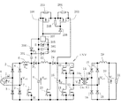
以下、図に沿って本発明の実施形態を説明する。
図1は、本発明の第1実施形態を示す回路図である。この第1実施形態は、図5に示した回路に、以下に述べる回路を付加したものである。なお、図5と同一部分については同一記号を付してその説明を省略する。
Hereinafter, embodiments of the present invention will be described with reference to the drawings.
FIG. 1 is a circuit diagram showing a first embodiment of the present invention. In the first embodiment, a circuit described below is added to the circuit shown in FIG. The same parts as those in FIG. 5 are denoted by the same reference numerals, and the description thereof is omitted.
すなわち、ダイオード8のカソードとダイオード24のカソードとの間には、MOSFET201,202が直列に接続され、これらのMOSFET201,202のソース電極、ゲート電極間には、抵抗値が等しい抵抗203,204がそれぞれ接続されている。また、207はゲート駆動回路であり、このゲート駆動回路207の両端には直流電源208が接続されている。ゲート駆動回路207から出力されるゲート駆動信号Gは、一方のMOSFET201のゲート電極に直接入力され、他方のMOSFET201のゲート電極にはダイオード206を介して入力されている。更に、MOSFET202のゲート電極とソース電極との間には、抵抗205が接続されている。
That is,
上記構成において、MOSFET201,202には、MOSFETからなる第1の半導体スイッチング素子7よりも耐圧の低い素子が用いられる。なお、図1において、MOSFETからなる別の半導体スイッチング素子23を、第2の半導体スイッチング素子というものとする。
ここで、平滑コンデンサ9の電圧Ed1が400[V]程度の回路では、スイッチング素子7として一般的に耐圧が500[V]または600[V]のものが使用されるが、MOSFET201,202の耐圧は何れも100[V]とする。MOSFET201,202の直列回路に印加される電圧はEd2とEd1との差電圧であり、実用的には、瞬低発生時に平滑コンデンサ9が放電した場合のEd1の下限値はEd2の1/2程度、例えばEd2が400[V]であればEd1の下限値は200[V]程度である。これは、同じ電力を得るためには、電圧低下に反比例して回路電流を増やす必要性があるので、Ed1が余りに低くなるまで放電させるのは部品の電流容量から得策ではないためである。
In the above configuration, the
Here, in a circuit in which the voltage E d1 of the smoothing capacitor 9 is about 400 [V], the switching element 7 generally has a breakdown voltage of 500 [V] or 600 [V]. The breakdown voltage is 100 [V] in all cases. The voltage applied to the series circuit of the
Ed2が400[V]、Ed1の下限値が200[V]程度の条件では、MOSFET201,202の直列回路に印加される電圧は200[V]以下となり、耐圧が100[V]のMOSFETを2個直列に接続した場合でも十分に対応することができる。ここで、耐圧が100[V]程度またはそれ以下のMOSFETは、特性が近年著しく改善されており、オン抵抗が極めて小さいものが市販されている。このため、耐圧が100[V]以下で小形のMOSFETを複数個直列に接続しても、直列オン抵抗をスイッチング素子7のオン抵抗より大幅に小さくすることができる。
Under the condition that E d2 is 400 [V] and the lower limit value of E d1 is about 200 [V], the voltage applied to the series circuit of the
ところで、一般にスイッチング素子の直列接続は並列接続に比べて困難である。これは各直列素子の駆動電位が異なるため、電位が独立した駆動回路を個別に設ける必要があるので、大きさ、コストの点で不利であり、またそれぞれの駆動回路にわずかでもタイミングずれがあるとスイッチング時に各素子の電圧アンバランスを生じ、電圧が集中した素子が過電圧破壊を起こす危険があるからである。従って、スイッチング素子の直列接続は、高電圧回路において1個の素子では耐圧が不足するような場合に止むを得ず行う場合がほとんどであり、直列接続しなくても耐圧を確保可能な条件で、意図的に低耐圧のスイッチング素子を直列接続することはまれである。 By the way, in general, it is difficult to connect the switching elements in series compared to the parallel connection. This is because the drive potential of each series element is different, and therefore it is necessary to provide a drive circuit with independent potentials, which is disadvantageous in terms of size and cost, and there is a slight timing shift in each drive circuit. This is because a voltage imbalance of each element is generated at the time of switching, and there is a risk that an element with a concentrated voltage may cause an overvoltage breakdown. Therefore, the series connection of switching elements is inevitably performed when a single element in a high-voltage circuit has insufficient withstand voltage, and it is inevitably performed under the condition that the withstand voltage can be secured without being connected in series. Intentionally, it is rare to intentionally connect low-voltage switching elements in series.
しかし、本実施形態において、MOSFET201,202は瞬低発生時に電圧Ed1が低下し始めるとスイッチング素子23がスイッチングを開始する前にオフし、瞬低が終わって電圧Ed1が再び上昇し、スイッチング素子23がスイッチングを停止した条件で再度オンする。つまり、MOSFET201,202のスイッチングはこれらの直列回路に電圧がほとんど加わっていないときにのみ行われるので、MOSFET201,202の間でスイッチングのタイミングを合わせる必要がない。また、同じ理由によりスイッチング損失が問題にならないので、例えば1[μs]以内に行うような高速スイッチングは必要なく、回路の電圧変化に対応できる時間、例えば数[μs]でスイッチングできれば良い。
However, in the present embodiment,
このため、本実施形態によれば、MOSFET201,202の駆動回路を極めて簡単に構成することができる。図1において、ゲート駆動回路207は、図中のG点を直流電源208の両端のV点またはS点(基準電位点)の何れかに接続する動作を行い、MOSFET201のゲート−ソース間電圧を直流電源208の電圧または0[V]とすることでMOSFET201のスイッチングを行う。ここで、G点−S点間に電圧を印加するとMOSFET201がオンし、MOSFET201の両端電圧は極めて小さくなるので、MOSFET202のゲートにも直流電源208の電圧にほぼ等しい電圧が印加され、MOSFET202もオンする。
For this reason, according to this embodiment, the drive circuit of MOSFET201,202 can be comprised very simply. In FIG. 1, the
一方、G点−S点間の電圧を0[V]とすると、MOSFET201がオフすると共にMOSFET202のゲート−ソース間寄生キャパシタンス(図示しない)が抵抗205により放電され、MOSFET202のゲート−ソース間電圧もやがて0[V]になるので、MOSFET202もオフする。
前述した昇圧チョッパの動作によりEd2がEd1より高くなると、MOSFET202のソース電位はS点の電位より高くなるが、この際のゲート駆動回路207との電位差はダイオード206が分担するため、MOSFET202のゲート−ソース間に過剰な逆電圧が加わることは防止される。また、このときMOSFET201,202の電圧分担は、抵抗203,204によってほぼ均等となるように分圧される。
On the other hand, when the voltage between the point G and the point S is 0 [V], the
When E d2 becomes higher than E d1 by the operation of the step-up chopper described above, the source potential of the
以上のように、図1の回路における適用条件、すなわち、MOSFET201,202の直列回路に電圧がほとんど加わっていない状態でスイッチングを行うこと、MOSFET201,202のスイッチングに高速性を要求されないことを勘案すれば、MOSFET201,202を直列接続して使用しても何ら問題は生じない。
図示されていないが、スイッチング素子7よりも耐圧の低いMOSFETを3個以上、直列接続した回路においても、図1におけるMOSFET202と同様に2段目以降のMOSFETのゲートをダイオードを介して共通のゲート駆動回路207に接続し、1段目のMOSFET201から順にオンしていくことで同様の動作が可能である。
As described above, considering the application conditions in the circuit of FIG. 1, that is, switching is performed with almost no voltage applied to the series circuit of the
Although not shown, even in a circuit in which three or more MOSFETs having a withstand voltage lower than that of the switching element 7 are connected in series, the gates of the second and subsequent MOSFETs are connected to the common gate via a diode in the same manner as the
次に、図2は本発明の第2実施形態を示す回路図である。この第2実施形態は、図1における直流電源208の構成に関するものである。
図2において、ゲート駆動回路207の両端にはツェナーダイオード305とコンデンサ302との並列回路が接続され、この並列回路の両端にはダイオード303,304が図示の極性で直列に接続されている。また、ダイオード303,304同士の接続点P2は、コンデンサ301を介してダイオード8のアノードに接続されている。
Next, FIG. 2 is a circuit diagram showing a second embodiment of the present invention. The second embodiment relates to the configuration of the
In FIG. 2, a
前述した図1におけるS点の電位はスイッチング素子7,23のソース電位(N点の電位)とは異なるため、スイッチング素子7,23の駆動回路とは基準電位が異なる直流電源208によってMOSFET201,202を駆動することが必要である。しかし、MOSFET201,202は元々駆動回路が不要な図6のダイオード101を置き換えたものであるため、MOSFET201,202の駆動電源等に起因して装置が大形化したりコストが上昇したりするのは望ましくない。
そこで、図2に示す第2実施形態は、スイッチング素子7,23とは基準電位が異なるMOSFET201,202の駆動電源を簡単に実現するためのものである。
Since the potential at the point S in FIG. 1 described above is different from the source potential of the switching elements 7 and 23 (potential at the N point), the
Therefore, the second embodiment shown in FIG. 2 is intended to easily realize the drive power supply for the
MOSFET201,202がオンするのは定常動作時であり、このときはスイッチング素子7がスイッチングを行っている。スイッチング素子7のスイッチング動作により、図2のN点に対するP1点の電位は、電圧Ed1と0[V]との間で高周波で変化する。
スイッチング素子7がオンすると、平滑コンデンサ9→ダイオード304→コンデンサ301→スイッチング素子7→平滑コンデンサ9の経路で電流が流れ、コンデンサ301はEd1にほぼ等しい電圧、例えば400[V]に充電される。スイッチング素子7がオフするとP1点の電位が上昇し、やがてダイオード8が導通するので、P1点の電位はS点の電位とほぼ等しくなる。その過程で、図中のP2点の電位はS点より高くなるので、コンデンサ301→P2→ダイオード303→コンデンサ302→S点の経路で電流が流れ、コンデンサ301に蓄積された電荷がコンデンサ302に移行する。
The
When the switching element 7 is turned on, a current flows through the path of the smoothing capacitor 9 → the
コンデンサの電圧はそのキャパシタンスに反比例するので、例えばコンデンサ301のキャパシタンスをコンデンサ302の1000分の1に設定しておくと、スイッチング素子7の1回のスイッチングでコンデンサ301を400[V]に充電した電荷がコンデンサ302に移行し、コンデンサ302の電圧は0.4[V]上昇することになる。
スイッチング素子7の高周波スイッチングにより上記の動作が繰り返されると、コンデンサ302の電圧は次第に上昇するが、ゲート駆動回路207や抵抗205により消費される電力が増加するため、原理的にはある点でコンデンサ302からの供給電力とゲート駆動回路207等による消費電力とがバランスし、コンデンサ302の電圧は一定となる。実用上は、このバランス点の電圧を管理することが困難なため、コンデンサ302に対して並列に接続されたツェナーダイオード305により、コンデンサ302の電圧を一定値に制限する。
Since the voltage of the capacitor is inversely proportional to its capacitance, for example, if the capacitance of the
When the above operation is repeated by the high-frequency switching of the switching element 7, the voltage of the
よく知られているように、MOSFETはオンを維持している間はゲートにおける消費電力がほとんどないので、コンデンサ301,302、ダイオード303,304及びツェナーダイオード305には電流容量の極めて小さい部品を使用することができる。MOSFET201,202がターンオンする瞬間は、コンデンサ302から一時的に電荷が供給される。このように、スイッチング素子7のように高周波スイッチングを行う素子と異なり、MOSFET201,202の駆動に要する電力は平均的には極めて小さいため、例えば絶縁形のDC/DCコンバータを用いるような方法に比べて、MOSFET201,202の駆動電源を簡単に構成することができる。
As is well known, since the MOSFET has almost no power consumption at the gate while it is kept on, the
本発明の電源装置は、情報・通信機器を始めとする各種の負荷に対して、交流電源電圧の瞬低時にも瞬低補償機能により一定の電圧を供給する用途に利用可能である。 The power supply apparatus of the present invention can be used for applications in which a constant voltage is supplied to various loads such as information / communication equipment even when the AC power supply voltage is instantaneously reduced by the instantaneous voltage drop compensation function.
1:交流電源
2〜4,8,15〜18,22,206:ダイオード
6,19,22:リアクトル
7,10〜13,23:半導体スイッチング素子
9,20,25:コンデンサ
14:変圧器
14a:一次巻線
14b:二次巻線
21:負荷
201,202:MOSFET
203〜205:抵抗
207:ゲート駆動回路
208:直流電源
301,302:コンデンサ
303,304:ダイオード
305:ツェナーダイオード
INV:インバータ
1: AC power supplies 2-4, 8, 15-18, 22, 206:
203 to 205: Resistor 207: Gate drive circuit 208:
Claims (7)
前記昇圧チョッパが、前記平滑コンデンサと前記インバータとの間の正側直流母線に互いに直列に接続されたリアクトル及びダイオードと、これらのリアクトルとダイオードとの接続点と負側直流母線との間に接続された第2の半導体スイッチング素子と、を有する電源装置において、
前記平滑コンデンサと前記リアクトルとの接続点と、前記ダイオードと前記インバータとの接続点と、の間に、前記第1の半導体スイッチング素子よりも耐圧が低く、かつスイッチング速度が遅い複数のMOSFETを直列に接続し、
前記複数のMOSFETを、前記交流電源電圧の瞬時低下時に前記第2の半導体スイッチング素子がスイッチングを開始する前にオフさせると共に、前記第2の半導体スイッチング素子がスイッチングを停止した条件のもとで前記複数のMOSFETの直列回路の両端の電位差がほぼゼロの状態でオンさせることを特徴とする電源装置。 A rectifier circuit for rectifying an AC power supply voltage, a first semiconductor switching element for controlling an input current waveform of the rectifier circuit to a sine wave, a smoothing capacitor to which an output voltage of the rectifier circuit is applied, and the smoothing capacitor A step-up chopper that boosts the voltage at both ends, and an inverter that converts a DC output voltage of the step-up chopper into an AC voltage and supplies the AC voltage to a load.
The step-up chopper is connected between a reactor and a diode connected in series to a positive DC bus between the smoothing capacitor and the inverter, and a connection point between the reactor and the diode and a negative DC bus. Oite to power supplies having a second semiconductor switching element, and
The smoothing capacitor and the connection point between the reactor and a connection point between the diode and the inverter, during the first breakdown voltage than the semiconductor switching elements is rather low, and multiple switching speed is not slow MOSFET Connected in series ,
The plurality of MOSFETs are turned off before the second semiconductor switching element starts switching when the AC power supply voltage is instantaneously reduced, and the second semiconductor switching element stops switching under the condition that the switching is stopped. A power supply device that is turned on with a potential difference between both ends of a series circuit of a plurality of MOSFETs being substantially zero .
前記複数のMOSFETを、交流電源電圧の瞬時低下時以外の通常動作時にオンさせることを特徴とする電源装置。 The power supply device according to claim 1,
The power supply device, wherein the plurality of MOSFETs are turned on during normal operation other than when the AC power supply voltage is instantaneously reduced .
前記複数のMOSFETを、共通のゲート駆動回路により駆動することを特徴とする電源装置。 In the power supply device according to claim 1 or 2 ,
It said plurality of MOSFET, the power supply apparatus characterized that you driven by a common gate driving circuit.
前記複数のMOSFETのうち少なくとも1個のMOSFETのゲート電極と前記ゲート駆動回路との間に、ダイオードを接続したことを特徴とする電源装置。 In the power supply device according to claim 3 ,
A power supply device comprising a diode connected between a gate electrode of at least one MOSFET of the plurality of MOSFETs and the gate drive circuit .
前記ゲート駆動回路に、前記平滑コンデンサと前記リアクトルとの接続点の電位を基準電位とする直流電源を接続したことを特徴とする電源装置。 In the power supply device according to claim 3 or 4,
A power supply apparatus , wherein a DC power supply having a reference potential as a potential at a connection point between the smoothing capacitor and the reactor is connected to the gate driving circuit .
前記複数のMOSFETの駆動電源として、
前記第1の半導体スイッチング素子のオンオフにより電荷が蓄積されるコンデンサと、このコンデンサの電圧を一定に保つ定電圧素子と、を備えたことを特徴とする電源装置。 In the power supply device according to claim 3 or 4 ,
As a driving power source for the plurality of MOSFETs,
A power supply apparatus comprising: a capacitor for accumulating charges by turning on and off the first semiconductor switching element; and a constant voltage element for maintaining a constant voltage of the capacitor .
前記インバータの交流出力電圧を絶縁して変圧する変圧器と、この変圧器の出力電圧を整流する整流回路と、を備え、前記整流回路の出力電圧を負荷に供給することを特徴とする電源装置。 In the power supply device according to any one of claims 1 to 6 ,
A power supply apparatus comprising: a transformer that insulates and transforms the AC output voltage of the inverter; and a rectifier circuit that rectifies the output voltage of the transformer, and supplies the output voltage of the rectifier circuit to a load. .
Priority Applications (3)
| Application Number | Priority Date | Filing Date | Title |
|---|---|---|---|
| JP2012226964A JP6065262B2 (en) | 2012-10-12 | 2012-10-12 | Power supply |
| US14/019,221 US9231479B2 (en) | 2012-10-12 | 2013-09-05 | Power supply device |
| CN201310410417.0A CN103731047B (en) | 2012-10-12 | 2013-09-10 | Power-supply device |
Applications Claiming Priority (1)
| Application Number | Priority Date | Filing Date | Title |
|---|---|---|---|
| JP2012226964A JP6065262B2 (en) | 2012-10-12 | 2012-10-12 | Power supply |
Publications (2)
| Publication Number | Publication Date |
|---|---|
| JP2014079144A JP2014079144A (en) | 2014-05-01 |
| JP6065262B2 true JP6065262B2 (en) | 2017-01-25 |
Family
ID=50455012
Family Applications (1)
| Application Number | Title | Priority Date | Filing Date |
|---|---|---|---|
| JP2012226964A Expired - Fee Related JP6065262B2 (en) | 2012-10-12 | 2012-10-12 | Power supply |
Country Status (3)
| Country | Link |
|---|---|
| US (1) | US9231479B2 (en) |
| JP (1) | JP6065262B2 (en) |
| CN (1) | CN103731047B (en) |
Families Citing this family (14)
| Publication number | Priority date | Publication date | Assignee | Title |
|---|---|---|---|---|
| CN103718447B (en) * | 2012-04-10 | 2017-06-23 | 富士电机株式会社 | Power converter |
| JP5804167B2 (en) * | 2013-09-19 | 2015-11-04 | ダイキン工業株式会社 | Power converter |
| US9588528B2 (en) * | 2014-12-01 | 2017-03-07 | Honeywell International Inc. | Inrush current suppression circuit and method for controlling when a load may be fully energized |
| CN106033936A (en) * | 2015-03-09 | 2016-10-19 | 光宝电子(广州)有限公司 | Power supply with by-pass function and operation method thereof |
| WO2016199497A1 (en) | 2015-06-11 | 2016-12-15 | 富士電機株式会社 | Power conversion device |
| TWI547079B (en) * | 2015-07-29 | 2016-08-21 | 台達電子工業股份有限公司 | High efficiency bridgeless power factor correction converter |
| US10284090B2 (en) * | 2016-10-20 | 2019-05-07 | Cirrus Logic, Inc. | Combined boost converter and power converter |
| EP3322076B1 (en) * | 2016-11-14 | 2020-02-05 | Siemens Aktiengesellschaft | Switching power supply with resonant converter |
| JP6843605B2 (en) * | 2016-12-06 | 2021-03-17 | キヤノン株式会社 | Power supply and image forming equipment |
| JP6706811B2 (en) * | 2016-12-12 | 2020-06-10 | パナソニックIpマネジメント株式会社 | Snubber circuit and power conversion system using the same |
| US10148212B2 (en) | 2017-01-06 | 2018-12-04 | Thermo King Corporation | DC to DC converter sourcing variable DC link voltage |
| JP6394741B1 (en) * | 2017-05-30 | 2018-09-26 | ダイキン工業株式会社 | Power converter, refrigeration equipment |
| SG11202011091QA (en) * | 2018-05-10 | 2020-12-30 | Toshiba Kk | Dc transformation system |
| CN111278195B (en) * | 2018-11-16 | 2022-04-29 | 朗德万斯公司 | Electronic transformer with peak current control for low power LED lamps |
Family Cites Families (13)
| Publication number | Priority date | Publication date | Assignee | Title |
|---|---|---|---|---|
| JPH02241371A (en) | 1989-03-14 | 1990-09-26 | Mitsubishi Electric Corp | Voltage type inverter |
| US5510747A (en) * | 1993-11-30 | 1996-04-23 | Siliconix Incorporated | Gate drive technique for a bidirectional blocking lateral MOSFET |
| JPH08185993A (en) | 1994-12-28 | 1996-07-16 | Matsushita Electric Works Ltd | Power unit |
| US5671128A (en) * | 1995-02-23 | 1997-09-23 | Matsushita Electric Works, Ltd. | Power supply apparatus |
| US6512352B2 (en) * | 2001-06-07 | 2003-01-28 | Koninklijke Philips Electronics N.V. | Active clamp step-down converter with power switch voltage clamping function |
| US7061212B2 (en) * | 2003-08-08 | 2006-06-13 | Astec International Limited | Circuit for maintaining hold-up time while reducing bulk capacitor size and improving efficiency in a power supply |
| JP2006167327A (en) * | 2004-12-20 | 2006-06-29 | Matsushita Electric Ind Co Ltd | Ultrasonograph |
| JP5693820B2 (en) | 2008-07-08 | 2015-04-01 | 富士電機株式会社 | Power supply |
| JP5278029B2 (en) * | 2009-02-23 | 2013-09-04 | オムロン株式会社 | Power factor correction circuit |
| US8390261B2 (en) * | 2010-05-21 | 2013-03-05 | Infineon Technologies Austria Ag | Maximum power point tracker bypass |
| JP5563425B2 (en) * | 2010-10-21 | 2014-07-30 | 富士通テレコムネットワークス株式会社 | Power supply |
| KR20120102308A (en) * | 2011-03-08 | 2012-09-18 | 주식회사 만도 | Apparatus to charge battery voltage for electric vehicle |
| US8558517B2 (en) * | 2011-09-15 | 2013-10-15 | Compuware Technology Inc. | Power supply with virtual by-pass system |
-
2012
- 2012-10-12 JP JP2012226964A patent/JP6065262B2/en not_active Expired - Fee Related
-
2013
- 2013-09-05 US US14/019,221 patent/US9231479B2/en not_active Expired - Fee Related
- 2013-09-10 CN CN201310410417.0A patent/CN103731047B/en not_active Expired - Fee Related
Also Published As
| Publication number | Publication date |
|---|---|
| US9231479B2 (en) | 2016-01-05 |
| CN103731047A (en) | 2014-04-16 |
| CN103731047B (en) | 2017-12-05 |
| US20140104889A1 (en) | 2014-04-17 |
| JP2014079144A (en) | 2014-05-01 |
Similar Documents
| Publication | Publication Date | Title |
|---|---|---|
| JP6065262B2 (en) | Power supply | |
| JP4881952B2 (en) | DC / DC power converter | |
| JP5049637B2 (en) | DC / DC power converter | |
| US8503199B1 (en) | AC/DC power converter with active rectification and input current shaping | |
| US9899910B2 (en) | Bridgeless PFC power converter with reduced EMI noise | |
| US9608524B2 (en) | DC power supply equipment | |
| JP5693820B2 (en) | Power supply | |
| JP2015035851A (en) | Switching power supply device | |
| CN109687702B (en) | DC-DC converter | |
| US11296607B2 (en) | DC-DC converter | |
| JP2016123258A (en) | Switching power source and charging device | |
| JP2008072856A (en) | Dc/dc power conversion system | |
| JP5471384B2 (en) | Inverter device for motor drive | |
| JP2012125090A (en) | Switching power supply and display device with it | |
| JP2014036491A (en) | Dc/dc power conversion device, and power conditioner for photovoltaic system | |
| JP6132086B2 (en) | DC voltage conversion circuit | |
| JP2022011002A (en) | Power regenerative snubber circuit and power supply | |
| JP2011130610A (en) | Voltage compensator and dc power supply system | |
| JP6442275B2 (en) | Power converter | |
| JP6458235B2 (en) | Switching power supply | |
| JP2014011907A (en) | Switching power-supply device | |
| US11190107B2 (en) | Auxiliary power supply circuit, power supply apparatus, and power supply circuit | |
| JP4939819B2 (en) | Three-phase rectifier | |
| WO2017122579A1 (en) | Phase-shifted full-bridge type power supply circuit | |
| JP7386737B2 (en) | Rectifier circuit and switching power supply using the same |
Legal Events
| Date | Code | Title | Description |
|---|---|---|---|
| A621 | Written request for application examination |
Free format text: JAPANESE INTERMEDIATE CODE: A621 Effective date: 20150914 |
|
| A131 | Notification of reasons for refusal |
Free format text: JAPANESE INTERMEDIATE CODE: A131 Effective date: 20160621 |
|
| A977 | Report on retrieval |
Free format text: JAPANESE INTERMEDIATE CODE: A971007 Effective date: 20160622 |
|
| A521 | Request for written amendment filed |
Free format text: JAPANESE INTERMEDIATE CODE: A523 Effective date: 20160728 |
|
| TRDD | Decision of grant or rejection written | ||
| A01 | Written decision to grant a patent or to grant a registration (utility model) |
Free format text: JAPANESE INTERMEDIATE CODE: A01 Effective date: 20161125 |
|
| A61 | First payment of annual fees (during grant procedure) |
Free format text: JAPANESE INTERMEDIATE CODE: A61 Effective date: 20161208 |
|
| R150 | Certificate of patent or registration of utility model |
Ref document number: 6065262 Country of ref document: JP Free format text: JAPANESE INTERMEDIATE CODE: R150 |
|
| LAPS | Cancellation because of no payment of annual fees |