JP6062938B2 - Thermally peelable adhesive article and method for producing and using the same - Google Patents
Thermally peelable adhesive article and method for producing and using the same Download PDFInfo
- Publication number
- JP6062938B2 JP6062938B2 JP2014521748A JP2014521748A JP6062938B2 JP 6062938 B2 JP6062938 B2 JP 6062938B2 JP 2014521748 A JP2014521748 A JP 2014521748A JP 2014521748 A JP2014521748 A JP 2014521748A JP 6062938 B2 JP6062938 B2 JP 6062938B2
- Authority
- JP
- Japan
- Prior art keywords
- shape memory
- adhesive
- memory polymer
- shape
- polymer sheet
- Prior art date
- Legal status (The legal status is an assumption and is not a legal conclusion. Google has not performed a legal analysis and makes no representation as to the accuracy of the status listed.)
- Expired - Fee Related
Links
Images


Classifications
-
- C—CHEMISTRY; METALLURGY
- C09—DYES; PAINTS; POLISHES; NATURAL RESINS; ADHESIVES; COMPOSITIONS NOT OTHERWISE PROVIDED FOR; APPLICATIONS OF MATERIALS NOT OTHERWISE PROVIDED FOR
- C09J—ADHESIVES; NON-MECHANICAL ASPECTS OF ADHESIVE PROCESSES IN GENERAL; ADHESIVE PROCESSES NOT PROVIDED FOR ELSEWHERE; USE OF MATERIALS AS ADHESIVES
- C09J5/00—Adhesive processes in general; Adhesive processes not provided for elsewhere, e.g. relating to primers
- C09J5/06—Adhesive processes in general; Adhesive processes not provided for elsewhere, e.g. relating to primers involving heating of the applied adhesive
-
- B—PERFORMING OPERATIONS; TRANSPORTING
- B32—LAYERED PRODUCTS
- B32B—LAYERED PRODUCTS, i.e. PRODUCTS BUILT-UP OF STRATA OF FLAT OR NON-FLAT, e.g. CELLULAR OR HONEYCOMB, FORM
- B32B3/00—Layered products comprising a layer with external or internal discontinuities or unevennesses, or a layer of non-planar form; Layered products having particular features of form
- B32B3/10—Layered products comprising a layer with external or internal discontinuities or unevennesses, or a layer of non-planar form; Layered products having particular features of form characterised by a discontinuous layer, i.e. formed of separate pieces of material
- B32B3/18—Layered products comprising a layer with external or internal discontinuities or unevennesses, or a layer of non-planar form; Layered products having particular features of form characterised by a discontinuous layer, i.e. formed of separate pieces of material characterised by an internal layer formed of separate pieces of material which are juxtaposed side-by-side
-
- B—PERFORMING OPERATIONS; TRANSPORTING
- B32—LAYERED PRODUCTS
- B32B—LAYERED PRODUCTS, i.e. PRODUCTS BUILT-UP OF STRATA OF FLAT OR NON-FLAT, e.g. CELLULAR OR HONEYCOMB, FORM
- B32B38/00—Ancillary operations in connection with laminating processes
- B32B38/10—Removing layers, or parts of layers, mechanically or chemically
-
- B—PERFORMING OPERATIONS; TRANSPORTING
- B32—LAYERED PRODUCTS
- B32B—LAYERED PRODUCTS, i.e. PRODUCTS BUILT-UP OF STRATA OF FLAT OR NON-FLAT, e.g. CELLULAR OR HONEYCOMB, FORM
- B32B5/00—Layered products characterised by the non- homogeneity or physical structure, i.e. comprising a fibrous, filamentary, particulate or foam layer; Layered products characterised by having a layer differing constitutionally or physically in different parts
- B32B5/18—Layered products characterised by the non- homogeneity or physical structure, i.e. comprising a fibrous, filamentary, particulate or foam layer; Layered products characterised by having a layer differing constitutionally or physically in different parts characterised by features of a layer of foamed material
-
- B—PERFORMING OPERATIONS; TRANSPORTING
- B32—LAYERED PRODUCTS
- B32B—LAYERED PRODUCTS, i.e. PRODUCTS BUILT-UP OF STRATA OF FLAT OR NON-FLAT, e.g. CELLULAR OR HONEYCOMB, FORM
- B32B7/00—Layered products characterised by the relation between layers; Layered products characterised by the relative orientation of features between layers, or by the relative values of a measurable parameter between layers, i.e. products comprising layers having different physical, chemical or physicochemical properties; Layered products characterised by the interconnection of layers
- B32B7/04—Interconnection of layers
- B32B7/12—Interconnection of layers using interposed adhesives or interposed materials with bonding properties
-
- C—CHEMISTRY; METALLURGY
- C09—DYES; PAINTS; POLISHES; NATURAL RESINS; ADHESIVES; COMPOSITIONS NOT OTHERWISE PROVIDED FOR; APPLICATIONS OF MATERIALS NOT OTHERWISE PROVIDED FOR
- C09J—ADHESIVES; NON-MECHANICAL ASPECTS OF ADHESIVE PROCESSES IN GENERAL; ADHESIVE PROCESSES NOT PROVIDED FOR ELSEWHERE; USE OF MATERIALS AS ADHESIVES
- C09J7/00—Adhesives in the form of films or foils
- C09J7/20—Adhesives in the form of films or foils characterised by their carriers
- C09J7/22—Plastics; Metallised plastics
-
- C—CHEMISTRY; METALLURGY
- C09—DYES; PAINTS; POLISHES; NATURAL RESINS; ADHESIVES; COMPOSITIONS NOT OTHERWISE PROVIDED FOR; APPLICATIONS OF MATERIALS NOT OTHERWISE PROVIDED FOR
- C09J—ADHESIVES; NON-MECHANICAL ASPECTS OF ADHESIVE PROCESSES IN GENERAL; ADHESIVE PROCESSES NOT PROVIDED FOR ELSEWHERE; USE OF MATERIALS AS ADHESIVES
- C09J7/00—Adhesives in the form of films or foils
- C09J7/30—Adhesives in the form of films or foils characterised by the adhesive composition
- C09J7/38—Pressure-sensitive adhesives [PSA]
-
- C—CHEMISTRY; METALLURGY
- C09—DYES; PAINTS; POLISHES; NATURAL RESINS; ADHESIVES; COMPOSITIONS NOT OTHERWISE PROVIDED FOR; APPLICATIONS OF MATERIALS NOT OTHERWISE PROVIDED FOR
- C09J—ADHESIVES; NON-MECHANICAL ASPECTS OF ADHESIVE PROCESSES IN GENERAL; ADHESIVE PROCESSES NOT PROVIDED FOR ELSEWHERE; USE OF MATERIALS AS ADHESIVES
- C09J2301/00—Additional features of adhesives in the form of films or foils
- C09J2301/10—Additional features of adhesives in the form of films or foils characterized by the structural features of the adhesive tape or sheet
- C09J2301/12—Additional features of adhesives in the form of films or foils characterized by the structural features of the adhesive tape or sheet by the arrangement of layers
- C09J2301/124—Additional features of adhesives in the form of films or foils characterized by the structural features of the adhesive tape or sheet by the arrangement of layers the adhesive layer being present on both sides of the carrier, e.g. double-sided adhesive tape
-
- C—CHEMISTRY; METALLURGY
- C09—DYES; PAINTS; POLISHES; NATURAL RESINS; ADHESIVES; COMPOSITIONS NOT OTHERWISE PROVIDED FOR; APPLICATIONS OF MATERIALS NOT OTHERWISE PROVIDED FOR
- C09J—ADHESIVES; NON-MECHANICAL ASPECTS OF ADHESIVE PROCESSES IN GENERAL; ADHESIVE PROCESSES NOT PROVIDED FOR ELSEWHERE; USE OF MATERIALS AS ADHESIVES
- C09J2301/00—Additional features of adhesives in the form of films or foils
- C09J2301/10—Additional features of adhesives in the form of films or foils characterized by the structural features of the adhesive tape or sheet
- C09J2301/18—Additional features of adhesives in the form of films or foils characterized by the structural features of the adhesive tape or sheet characterized by perforations in the adhesive tape
-
- C—CHEMISTRY; METALLURGY
- C09—DYES; PAINTS; POLISHES; NATURAL RESINS; ADHESIVES; COMPOSITIONS NOT OTHERWISE PROVIDED FOR; APPLICATIONS OF MATERIALS NOT OTHERWISE PROVIDED FOR
- C09J—ADHESIVES; NON-MECHANICAL ASPECTS OF ADHESIVE PROCESSES IN GENERAL; ADHESIVE PROCESSES NOT PROVIDED FOR ELSEWHERE; USE OF MATERIALS AS ADHESIVES
- C09J2301/00—Additional features of adhesives in the form of films or foils
- C09J2301/30—Additional features of adhesives in the form of films or foils characterized by the chemical, physicochemical or physical properties of the adhesive or the carrier
- C09J2301/302—Additional features of adhesives in the form of films or foils characterized by the chemical, physicochemical or physical properties of the adhesive or the carrier the adhesive being pressure-sensitive, i.e. tacky at temperatures inferior to 30°C
-
- C—CHEMISTRY; METALLURGY
- C09—DYES; PAINTS; POLISHES; NATURAL RESINS; ADHESIVES; COMPOSITIONS NOT OTHERWISE PROVIDED FOR; APPLICATIONS OF MATERIALS NOT OTHERWISE PROVIDED FOR
- C09J—ADHESIVES; NON-MECHANICAL ASPECTS OF ADHESIVE PROCESSES IN GENERAL; ADHESIVE PROCESSES NOT PROVIDED FOR ELSEWHERE; USE OF MATERIALS AS ADHESIVES
- C09J2301/00—Additional features of adhesives in the form of films or foils
- C09J2301/50—Additional features of adhesives in the form of films or foils characterized by process specific features
- C09J2301/502—Additional features of adhesives in the form of films or foils characterized by process specific features process for debonding adherents
-
- C—CHEMISTRY; METALLURGY
- C09—DYES; PAINTS; POLISHES; NATURAL RESINS; ADHESIVES; COMPOSITIONS NOT OTHERWISE PROVIDED FOR; APPLICATIONS OF MATERIALS NOT OTHERWISE PROVIDED FOR
- C09J—ADHESIVES; NON-MECHANICAL ASPECTS OF ADHESIVE PROCESSES IN GENERAL; ADHESIVE PROCESSES NOT PROVIDED FOR ELSEWHERE; USE OF MATERIALS AS ADHESIVES
- C09J2423/00—Presence of polyolefin
- C09J2423/04—Presence of homo or copolymers of ethene
- C09J2423/046—Presence of homo or copolymers of ethene in the substrate
-
- C—CHEMISTRY; METALLURGY
- C09—DYES; PAINTS; POLISHES; NATURAL RESINS; ADHESIVES; COMPOSITIONS NOT OTHERWISE PROVIDED FOR; APPLICATIONS OF MATERIALS NOT OTHERWISE PROVIDED FOR
- C09J—ADHESIVES; NON-MECHANICAL ASPECTS OF ADHESIVE PROCESSES IN GENERAL; ADHESIVE PROCESSES NOT PROVIDED FOR ELSEWHERE; USE OF MATERIALS AS ADHESIVES
- C09J2465/00—Presence of polyphenylene
- C09J2465/006—Presence of polyphenylene in the substrate
-
- C—CHEMISTRY; METALLURGY
- C09—DYES; PAINTS; POLISHES; NATURAL RESINS; ADHESIVES; COMPOSITIONS NOT OTHERWISE PROVIDED FOR; APPLICATIONS OF MATERIALS NOT OTHERWISE PROVIDED FOR
- C09J—ADHESIVES; NON-MECHANICAL ASPECTS OF ADHESIVE PROCESSES IN GENERAL; ADHESIVE PROCESSES NOT PROVIDED FOR ELSEWHERE; USE OF MATERIALS AS ADHESIVES
- C09J2475/00—Presence of polyurethane
- C09J2475/006—Presence of polyurethane in the substrate
-
- G—PHYSICS
- G09—EDUCATION; CRYPTOGRAPHY; DISPLAY; ADVERTISING; SEALS
- G09F—DISPLAYING; ADVERTISING; SIGNS; LABELS OR NAME-PLATES; SEALS
- G09F7/00—Signs, name or number plates, letters, numerals, or symbols; Panels or boards
- G09F7/18—Means for attaching signs, plates, panels, or boards to a supporting structure
- G09F2007/1873—Means for attaching signs, plates, panels, or boards to a supporting structure characterised by the type of sign
- G09F2007/1895—Licence number plates
-
- Y—GENERAL TAGGING OF NEW TECHNOLOGICAL DEVELOPMENTS; GENERAL TAGGING OF CROSS-SECTIONAL TECHNOLOGIES SPANNING OVER SEVERAL SECTIONS OF THE IPC; TECHNICAL SUBJECTS COVERED BY FORMER USPC CROSS-REFERENCE ART COLLECTIONS [XRACs] AND DIGESTS
- Y10—TECHNICAL SUBJECTS COVERED BY FORMER USPC
- Y10T—TECHNICAL SUBJECTS COVERED BY FORMER US CLASSIFICATION
- Y10T156/00—Adhesive bonding and miscellaneous chemical manufacture
- Y10T156/10—Methods of surface bonding and/or assembly therefor
- Y10T156/1052—Methods of surface bonding and/or assembly therefor with cutting, punching, tearing or severing
- Y10T156/1062—Prior to assembly
-
- Y—GENERAL TAGGING OF NEW TECHNOLOGICAL DEVELOPMENTS; GENERAL TAGGING OF CROSS-SECTIONAL TECHNOLOGIES SPANNING OVER SEVERAL SECTIONS OF THE IPC; TECHNICAL SUBJECTS COVERED BY FORMER USPC CROSS-REFERENCE ART COLLECTIONS [XRACs] AND DIGESTS
- Y10—TECHNICAL SUBJECTS COVERED BY FORMER USPC
- Y10T—TECHNICAL SUBJECTS COVERED BY FORMER US CLASSIFICATION
- Y10T156/00—Adhesive bonding and miscellaneous chemical manufacture
- Y10T156/11—Methods of delaminating, per se; i.e., separating at bonding face
- Y10T156/1142—Changing dimension during delaminating [e.g., crushing, expanding, warping, etc.]
-
- Y—GENERAL TAGGING OF NEW TECHNOLOGICAL DEVELOPMENTS; GENERAL TAGGING OF CROSS-SECTIONAL TECHNOLOGIES SPANNING OVER SEVERAL SECTIONS OF THE IPC; TECHNICAL SUBJECTS COVERED BY FORMER USPC CROSS-REFERENCE ART COLLECTIONS [XRACs] AND DIGESTS
- Y10—TECHNICAL SUBJECTS COVERED BY FORMER USPC
- Y10T—TECHNICAL SUBJECTS COVERED BY FORMER US CLASSIFICATION
- Y10T428/00—Stock material or miscellaneous articles
- Y10T428/24—Structurally defined web or sheet [e.g., overall dimension, etc.]
- Y10T428/24802—Discontinuous or differential coating, impregnation or bond [e.g., artwork, printing, retouched photograph, etc.]
Description
本開示は、熱により剥離できる接着剤物品に関する。 The present disclosure relates to an adhesive article that can be peeled off by heat.
感圧接着剤及び構造接着剤などの接着剤は、例えば、電子機器、自動車、研磨、医療用装置、及び光学機器といった多様な産業において、組み立て物品への部品の接着に一般的に用いられる。例えば、自動車産業では、構造接着剤を用いて、バックミラーなどの部品をフロントガラスに接着させることができる。又は、光学的に透明な接着剤を用いて、光学フィルム、電磁シールド、又は更にはタッチセンサー式フィルムを、例えば、携帯電話、パソコン、又はタブレット型コンピュータなどの電子装置に接着させることができる。物品のコストが高く、接着されたフィルムのコストが比較的低いことから、物品の修理、物品の調整、物品上でのフィルムの再配置、又は接着された物品のリサイクルには、接着された部品を外す(剥離する)ことが望まれる場合がある。 Adhesives such as pressure sensitive adhesives and structural adhesives are commonly used for bonding components to assembled articles in a variety of industries such as, for example, electronic equipment, automobiles, polishing, medical devices, and optical equipment. For example, in the automobile industry, components such as a rearview mirror can be bonded to a windshield using a structural adhesive. Alternatively, an optical film, an electromagnetic shield, or even a touch-sensitive film can be adhered to an electronic device such as a mobile phone, a personal computer, or a tablet computer using an optically transparent adhesive. Because the cost of the article is high and the cost of the glued film is relatively low, the glued part is used for repairing the article, conditioning the article, repositioning the film on the article, or recycling the glued article. It may be desired to remove (peel).
この用途のため、再加工可能かつ再配置可能な感圧接着剤が開発されている。典型的には、このような接着剤は、一方の基材、例えば、フロントガラス又は電子ディスプレーよりも、もう一方の基材、例えば、付着されたフィルムの方にはるかに強く接着する。そのため接着剤を、よりコストが高い製品からきれいに除去でき、付着されたフィルムは再加工又は再配置できる。接着剤を一方に伸張させて接着性を低下させることによって剥がすことができる接着剤が周知である。これらの接着剤のうち一部は、商品名COMMANDで販売されており、3M(St.Paul,MN)から入手できる。 For this application, reworkable and repositionable pressure sensitive adhesives have been developed. Typically, such adhesives adhere much more strongly to one substrate, such as an attached film, than one substrate, such as a windshield or electronic display. Thus, the adhesive can be cleanly removed from the more costly product and the deposited film can be reworked or repositioned. Adhesives that can be peeled off by stretching the adhesive in one direction to reduce adhesion are well known. Some of these adhesives are sold under the trade name COMMAND and are available from 3M (St. Paul, MN).
形状記憶性を利用して、感圧接着剤を剥離できる。米国特許第5,888,650号(Calhounら)は、第1転移温度でその三次元形状を変えられる温度応答性キャリア、及びキャリアの少なくとも一方の表面の少なくとも一部上にある熱形態感圧接着剤の使用を教示している。熱形態感圧接着剤は、第2転移温度でその三次元形状を変えられる。キャリア及び接着剤の形態の初期形状、並びに転移温度間の関係に変化を持たせることで、様々な接着及び剥離特性を提供できる。 The pressure sensitive adhesive can be peeled using shape memory. US Pat. No. 5,888,650 (Calhoun et al.) Describes a temperature responsive carrier that can change its three-dimensional shape at a first transition temperature, and thermal form pressure sensitivity on at least a portion of at least one surface of the carrier. Teaches the use of adhesives. The thermal form pressure sensitive adhesive can change its three-dimensional shape at the second transition temperature. By varying the initial shape of the carrier and adhesive forms as well as the relationship between the transition temperatures, various adhesion and release properties can be provided.
熱形態特性を有する必要がない、従来の接着剤を使用できる熱剥離可能な接着剤物品のニーズが存在する。同物品の修理又は耐用期間を経てからの分解が可能な、熱剥離可能な物品のニーズが存在する。また、例えば電子産業において、光学的透明性を有し、例えば電子装置の再加工のためにきれいに除去できる、電子ディスプレー上のオーバーレイなどの剥離可能な接着剤物品のニーズも存在する。 There is a need for thermally peelable adhesive articles that can use conventional adhesives that do not need to have thermomorphic properties. There is a need for a thermally peelable article that can be repaired or disassembled after a lifetime. There is also a need for peelable adhesive articles such as overlays on electronic displays that have optical transparency and can be removed cleanly, for example, for reworking of electronic devices, for example in the electronics industry.
一態様では、歪んだ一時的な形状及び固有形状と第1及び第2の対向する表面とを有し、それぞれがその内部に幅を有する複数のスリットのうち少なくとも1つを含む領域を有し、この複数のスリットが全スリット長を画定し、そして、転移温度範囲以上に加熱されると、形状記憶シートがその歪んだ一時的な形状から固有形状に少なくとも部分的に変換される形状記憶ポリマーシートと、第1の厚さ、並びに第1及び第2の対向する表面を有し、第1接着剤が感圧接着剤を含み、第1接着剤層の第1の対向する表面の大部分が、歪んだ一時的な形状にある形状記憶ポリマーシートの第1の対向する表面の大部分上に配置される、第1接着剤と、第2の厚さ、第1及び第2の対向する面を有し、第2接着剤の第1の対向する面の大部分が、歪んだ一時的な形状にある形状記憶ポリマーの第2の対向する面の大部分上に配置される、第2接着剤と、を備える、熱剥離可能な接着剤物品が提供される。提供される剥離可能な接着剤物品は、所望により、第1接着剤層の第2の対向する表面の大部分と接する面を有する第1基材と、所望により、第2接着剤の第2の対向する面の大部分と接する第2基材と、を含んでもよい。 In one aspect, having a distorted temporary shape and unique shape and first and second opposing surfaces, each having a region including at least one of a plurality of slits having a width therein A shape memory polymer in which the plurality of slits define a total slit length and when the shape memory sheet is at least partially converted from its distorted temporary shape to an intrinsic shape when heated above the transition temperature range A sheet, a first thickness, and first and second opposing surfaces, wherein the first adhesive comprises a pressure sensitive adhesive, and a majority of the first opposing surfaces of the first adhesive layer Is disposed on a majority of the first opposing surface of the shape memory polymer sheet in a distorted temporary shape, the first adhesive, the second thickness, the first and second opposing Most of the first opposing surface of the second adhesive is strained It is disposed on the second opposed on most of the surface of the shape memory polymer in the temporary shape comprises a second adhesive, a heat-releasable adhesive article is provided. The peelable adhesive article provided optionally includes a first substrate having a surface that contacts a majority of the second opposing surface of the first adhesive layer, and optionally a second of the second adhesive. And a second base that contacts most of the opposing surfaces.
形状記憶ポリマーシートは、物理的架橋を含んでもよく、いくつかの実施形態では、熱可塑性ウレタン又は直鎖状高分子ポリノルボルネンを含んでもよい。別の実施形態では、形状記憶ポリマーシートは、エポキシ、熱硬化性ウレタン、アクリレート、スチレンポリマー、架橋オレフィン、又は架橋開環メタセシスポリマーなどに見出される、共有結合性架橋を含んでもよい。形状記憶ポリマーシートを、例えば、コロナ処理又は化学処理によって官能化できる。複数のスリットによって、形状記憶ポリマーシートを2つ以上の部分に分けることができ、いくつかの実施形態では、直交平行模様を含んでもよい。 The shape memory polymer sheet may include physical cross-linking, and in some embodiments may include thermoplastic urethane or linear polymeric polynorbornene. In another embodiment, the shape memory polymer sheet may include covalent crosslinks found in epoxies, thermoset urethanes, acrylates, styrene polymers, cross-linked olefins, cross-linked ring-opening metathesis polymers, and the like. The shape memory polymer sheet can be functionalized, for example, by corona treatment or chemical treatment. A plurality of slits can divide the shape memory polymer sheet into two or more parts, and in some embodiments may include orthogonal parallel patterns.
別の態様では、歪んだ一時的な形状及び固有形状、第1及び第2の対向する面を有し、内部にそれぞれが幅を有する複数のスリットを含み、転移温度範囲以上に加熱されると、形状記憶シートがその歪んだ一時的な形状から固有形状に少なくとも部分的に変換される形状記憶ポリマーシートと、第1及び第2の対向する面を有し、第1面の大部分が、形状記憶ポリマーの第1の対向する面に配置されている第1接着剤と、を準備することと、第1接着剤の第2の対向する面を第1基材に適用することと、を含む、剥離可能な接着剤物品の製造方法が提供される。提供される方法は、第2接着剤の第1の対向する面を第2基材に適用することと、第2接着剤の第2の対向する面の大部分を、形状記憶ポリマーシートの第2の対向する面の大部分に配置することと、を更に含んでもよい。 In another aspect, having a distorted temporary shape and inherent shape, first and second opposing faces, each having a plurality of slits each having a width, when heated above the transition temperature range The shape memory sheet has a shape memory polymer sheet that is at least partially converted from its distorted temporary shape to an intrinsic shape, and first and second opposing surfaces, the majority of the first surface being: Providing a first adhesive disposed on a first opposing surface of the shape memory polymer; and applying a second opposing surface of the first adhesive to the first substrate. A method of manufacturing a peelable adhesive article is provided. The provided method includes applying a first opposing surface of the second adhesive to the second substrate, and applying a majority of the second opposing surface of the second adhesive to the first of the shape memory polymer sheet. And disposing on most of the two opposing surfaces.
更に別の態様では、歪んだ一時的な形状及び固有形状、転移温度、第1及び第2の対向する表面を有し、内部に複数のスリットを含む外辺部を備える形状記憶ポリマーシートと、第1の厚さ、並びに第1及び第2の対向する表面を有し、第1接着剤層の第1の対向する表面の大部分が、歪んだ一時的な形状にある形状記憶ポリマーシートの第1の対向する表面の大部分上に配置される第1接着剤層と、第1接着剤層の第2の対向する表面の大部分と接する面を有する第1基材と、第1の厚さ、並びに第1及び第2の対向する表面を有し、第2接着剤層の第1の対向する表面の大部分が、歪んだ一時的な形状にある形状記憶ポリマーシートの第2の対向する表面上に配置される第2接着剤と、第2接着剤層の第2の対向する表面の大部分と接する面を有する第2基材と、を含む、第1及び第2の対向する面を有する第1基材を含む物品を準備することと、第1転移温度を超える第1温度まで物品を加熱し、形状記憶ポリマーシートをその歪んだ一時的な形状から固有形状に変換することと、第2基材から第1基材を剥離することと、を含む、接着剤物品の剥離方法が提供される。 In yet another aspect, a shape memory polymer sheet having a distorted temporary shape and intrinsic shape, a transition temperature, first and second opposing surfaces, and comprising an outer side including a plurality of slits therein, A shape memory polymer sheet having a first thickness and first and second opposing surfaces, wherein a majority of the first opposing surface of the first adhesive layer is in a distorted temporary shape. A first adhesive layer disposed on a majority of the first opposing surface; a first substrate having a surface in contact with a majority of the second opposing surface of the first adhesive layer; A second of the shape memory polymer sheet having a thickness and a first and second opposing surface, wherein a majority of the first opposing surface of the second adhesive layer is in a distorted temporary shape; A second adhesive disposed on the opposing surface and in contact with a majority of the second opposing surface of the second adhesive layer Providing an article comprising a first substrate having first and second opposing faces, and heating the article to a first temperature that exceeds the first transition temperature. There is provided a method for peeling an adhesive article, comprising: converting a shape memory polymer sheet from its distorted temporary shape to an intrinsic shape; and peeling the first substrate from the second substrate. .
本開示において、
「エラストマー」材料とは、例えば、元の長さの少なくとも2倍にまで伸ばすことができ、力を解放するとほぼ元の寸法(一般的には、少なくとも約75%、又は少なくとも約90%)に速やか、かつ強制的に収縮する非晶質性又は部分的非結晶性材料として述べることができる材料を意味する。
「固有形状」は、形状記憶ポリマーが、その転移温度以上に加熱されると戻る形状を意味する。
「多官能性」は、フリーラジカル重合可能なエチレン性不飽和基、イソシアネート基、ヒドロキシル基、チオール基、又はその他などの2つ以上の反応性部位を有する架橋剤を意味する。
「スリット」は、提供される形状記憶フィルムなどのフィルム中の切れ目又は薄い切り取り部を意味し、完全にフィルム内にあってもよく、フィルムの任意の外辺部に接してもよく、接着剤が互いに強く接着しない場合など特に記載のない限り、上部に配置される接着剤の厚さを超えない幅を有してもよい。
「形状記憶転移温度範囲」は、形状記憶ポリマーがその歪んだ一時的な形状から固有形状へと寸法を変える温度範囲、又はそれを超える温度範囲を意味する。
「歪んだ一時的な形状」は、転移温度範囲を超えて加熱され、歪ませられ、その後転移温度範囲以下に冷却されたときの形状記憶ポリマーの形状を意味する。
「転移温度範囲」は、形状記憶転移温度範囲を意味する。
In this disclosure,
“Elastomeric” material, for example, can be stretched to at least twice its original length, to approximately its original dimensions (typically at least about 75%, or at least about 90%) upon release of force. It means a material that can be described as an amorphous or partially amorphous material that quickly and forcefully shrinks.
“Intrinsic shape” means the shape that a shape memory polymer returns to when it is heated above its transition temperature.
“Polyfunctional” means a crosslinker having two or more reactive sites such as free radical polymerizable ethylenically unsaturated groups, isocyanate groups, hydroxyl groups, thiol groups, or others.
“Slit” means a cut or thin cut in a film, such as a provided shape memory film, which may be completely within the film, may be in contact with any outer edge of the film, adhesive Unless otherwise noted, such as when they do not adhere strongly to each other, they may have a width that does not exceed the thickness of the adhesive disposed on top.
By “shape memory transition temperature range” is meant a temperature range in which a shape memory polymer changes dimensions from its distorted temporary shape to an intrinsic shape, or beyond.
“Strained temporary shape” means the shape of the shape memory polymer when heated above the transition temperature range, distorted and then cooled below the transition temperature range.
“Transition temperature range” means the shape memory transition temperature range.
提供される熱接着可能な接着剤物品を用いて、従来の感圧接着剤を剥離できる。これら従来の感圧接着剤は、熱形態特性を有する必要がない場合がある。提供される接着剤物品は、上部に積層シートを有する製品、例えば、電子ディスプレーパネル上のオーバーレイの修理又は耐用期間を経てからの分解が可能である。提供される剥離可能な接着剤物品は光学的透明性を有し、例えば、電子装置からきれいに除去できる。 Conventional pressure sensitive adhesives can be peeled off using the provided heat-bondable adhesive article. These conventional pressure sensitive adhesives may not need to have thermal morphology characteristics. The provided adhesive articles can be disassembled after repair or lifetime of an article with a laminated sheet on top, such as an overlay on an electronic display panel. The provided peelable adhesive article is optically clear and can be cleanly removed from, for example, electronic devices.
上記の概要は、本発明の全ての実施のそれぞれの開示される実施形態を説明することを目的としたものではない。後続の図面の簡単な説明及び発明を実施するための形態は、代表的な実施形態をより具体的に例示する。 The above summary is not intended to describe each disclosed embodiment of every implementation of the present invention. The following brief description of the drawings and the detailed description illustrate exemplary embodiments more specifically.
以下の説明において、本明細書の説明の一部を形成する添付されている図面の組が参照されるが、これらはいくつかの具体的な実施形態の例示により示されている。本発明の範囲又は趣旨を逸脱せずに、その他の実施形態が考えられ、実施され得ることを理解すべきである。したがって、以下の詳細な説明は、限定的な意味で解釈されるべきではない。 In the following description, reference is made to the accompanying set of drawings, which form a part of the description herein, which are shown by way of illustration of some specific embodiments. It should be understood that other embodiments may be envisaged and practiced without departing from the scope or spirit of the invention. The following detailed description is, therefore, not to be construed in a limiting sense.
特に断りがない限り、本明細書及び添付の「特許請求の範囲」で使用される構造のサイズ、量、及び物理的特性を表わす数字は全て、いずれの場合においても「約」なる語によって修飾されているものとして理解されるべきである。それ故に、そうでないことが示されない限り、前述の明細書及び添付の「特許請求の範囲」で示される数値パラメーターは、当業者が本明細書で開示される教示内容を用いて、目標対象とする所望の特性に応じて、変化し得る近似値である。終点による数の範囲の使用は、その範囲内(例えば、1〜5は、1、1.5、2、2.75、3、3.80、4、及び5を含む)の全ての数及びその範囲内の任意の範囲を含む。 Unless otherwise indicated, all numbers representing the size, quantity, and physical properties of structures used in this specification and the appended claims are, in each case, modified by the word “about”. Should be understood as being. Therefore, unless indicated to the contrary, the numerical parameters set forth in the foregoing specification and the appended claims are intended to be used by those skilled in the art using the teachings disclosed herein. It is an approximate value that can vary depending on the desired characteristics to be performed. The use of a range of numbers by endpoint means that all numbers within that range (eg 1 to 5 include 1, 1.5, 2, 2.75, 3, 3.80, 4, and 5) and Includes any range within that range.
形状記憶材料が最初に形成されるとき、固有形状をとる。形状記憶材料が、その後転移温度(Ttrans)以上で加熱されると、材料は軟化し、適用された外部応力に対応して変形する。形状記憶材料がこの状態で冷却されると、材料は、歪んだ一時的な形状を永久に維持する。歪んだ形状記憶材料が、形状記憶転移温度よりも高い十分な高温まで再加熱されると、歪んだ形状記憶材料はその固有形状に戻る。 When the shape memory material is first formed, it takes an intrinsic shape. When the shape memory material is subsequently heated above the transition temperature (T trans) , the material softens and deforms in response to the applied external stress. When the shape memory material is cooled in this state, the material permanently maintains a distorted temporary shape. When the strained shape memory material is reheated to a sufficiently high temperature above the shape memory transition temperature, the strained shape memory material returns to its native shape.
一部のポリマー材料は、形状記憶材料である。便宜上、そのようなポリマー形状記憶材料を、以下形状記憶ポリマー(SMP)と呼ぶ。SMPの後の機序は、典型的には物理的又は化学的架橋を含むその分子ネットワーク構造にある。場合によっては、物理的架橋は、少なくとも2つの分離相により形成される。最高温度遷移(Tupper)を有する一方の相は、固有形状に関与する物理的架橋を再構築するために超えなければならない温度を決定する。第2の相は、一定の転移温度(Ttrans)以上で軟化する能力を有するスイッチセグメントを含み、一時的形状に関与する。場合によっては、Ttransはガラス転移温度(Tg)に近く、別の場合では、SMPの融解温度(Tm)に近い。Ttransを超えると(Tupper未満を維持しながら)、スイッチセグメントは軟化して、SMPはその固有形状を再びとることが可能となる。Ttrans未満では、セグメントの可撓性は、少なくとも部分的に制限される。 Some polymeric materials are shape memory materials. For convenience, such polymer shape memory materials are hereinafter referred to as shape memory polymers (SMP). The mechanism behind SMP is in its molecular network structure, which typically includes physical or chemical cross-linking. In some cases, the physical crosslink is formed by at least two separate phases. One phase with the highest temperature transition (T upper ) determines the temperature that must be exceeded in order to reconstruct the physical cross-links involved in the intrinsic shape. The second phase includes a switch segment that has the ability to soften above a certain transition temperature (T trans ) and is involved in the temporary shape. In some cases, T trans is close to the glass transition temperature (T g ), and in other cases, close to the melting temperature (T m ) of SMP. Beyond T trans (while maintaining below T upper ), the switch segment softens, allowing the SMP to take its native shape again. Below T trans , the flexibility of the segment is at least partially limited.
別の場合では、ポリマーは化学的に架橋される。このような化学的架橋は、共有結合である場合が多い。多くの場合、重合混合物中に多官能性モノマーを含ませることによって、ポリマーが最初に硬化されたときにこのような化学的架橋が形成され得る。あるいは、化学的架橋は、例えば、紫外線又は電子ビームなどの放射線による初期重合の後に形成され得る。化学的に架橋された形状記憶ポリマーの固有形状は、架橋が形成されたときに固定され、このような化学的に架橋されたポリマーのこの固有形状は、通常、極端な温度においてでさえ変化させることはできない。 In other cases, the polymer is chemically crosslinked. Such chemical cross-linking is often a covalent bond. In many cases, by including a polyfunctional monomer in the polymerization mixture, such chemical cross-linking can be formed when the polymer is first cured. Alternatively, chemical crosslinks can be formed after initial polymerization, for example by radiation such as ultraviolet light or electron beams. The intrinsic shape of a chemically cross-linked shape memory polymer is fixed when the cross-link is formed, and this intrinsic shape of such a chemically cross-linked polymer usually changes even at extreme temperatures It is not possible.
有用なSMPは、物理的及び/又は化学的に架橋されてもよい。好適な物理的に架橋されたSMPには、ハードセグメント及びソフトスイッチセグメントを有する熱可塑性ポリウレタンエラストマーなどの直鎖ブロックコポリマーが含まれる。マルチブロックコポリマー、例えば、ポリスチレン及びポリ(1,4−ブタジエン)のブロックを有するポリウレタン、ポリ(テトラヒドロフラン)及びポリ(2−メチル−2−オキサゾリン)のABA型トリブロックコポリマー、多面体オリゴマシルセスキオキサン(POSS)修飾ポリノルボルネン、並びにポリエチレン/ナイロン−6グラフトコポリマーなどもまた、SMPとして機能することもできる。 Useful SMPs may be physically and / or chemically crosslinked. Suitable physically crosslinked SMPs include linear block copolymers such as thermoplastic polyurethane elastomers having hard segments and soft switch segments. Multiblock copolymers, for example polyurethanes with blocks of polystyrene and poly (1,4-butadiene), ABA type triblock copolymers of poly (tetrahydrofuran) and poly (2-methyl-2-oxazoline), polyhedral oligomeric silsesquioxanes (POSS) modified polynorbornene, as well as polyethylene / nylon-6 graft copolymers, etc. can also function as SMPs.
好適な化学的に架橋された形状記憶ポリマーの例としては、架橋高密度ポリエチレン、架橋低密度ポリエチレン、並びにエチレン及びビニルアセテートの架橋コポリマーが挙げられるが、これらに限定されない。 Examples of suitable chemically crosslinked shape memory polymers include, but are not limited to, crosslinked high density polyethylene, crosslinked low density polyethylene, and crosslinked copolymers of ethylene and vinyl acetate.
形状記憶ポリマーの他の例としては、ポリウレタン、ポリノルボルネン、ポリエーテル、ポリアクリレート、ポリアミド、ポリシロキサン、ポリエーテルアミド、ポリエーテルエステル、トランスポリイソプレン、ポリメタクリル酸メチル、架橋トランスポリオクチレン、架橋ポリエチレン、架橋ポリシクロオクテン、無機−有機ハイブリッドポリマー、ポリエチレン及びスチレン/ブタジエンコポリマーを含むコポリマーブレンド、ウレタン−ブタジエンコポリマー、ポリメチルメタクリレート、ポリカプロラクトン、並びにオリゴカプロラクトンコポリマー(oligocaprolactone copolymers)が挙げられる。好適な形状記憶ポリマーは、米国特許第5,506,300号(Wardら)、同第5,145,935号(Hayashi)、同第5,665,822号(Bitlerら)、同第6,160,084号(Langer)、同第6,388,043号(Langer)、同第5,155,199号(Hayashi)、同第7,173,096号(Matherら)、同第4,436,858号(Klosiewicz)、同第6,423,421号(Banaszak)、並びに、米国特許出願公開第2005/244353号(Lendleinら)、同第2007/009465号(Lendleinら)、及び同第2006/041089号(Matherら)に記載されているものも含む。 Other examples of shape memory polymers include polyurethane, polynorbornene, polyether, polyacrylate, polyamide, polysiloxane, polyether amide, polyether ester, trans polyisoprene, polymethyl methacrylate, cross-linked trans polyoctylene, cross-linked Mention may be made of polyethylene, crosslinked polycyclooctene, inorganic-organic hybrid polymers, copolymer blends comprising polyethylene and styrene / butadiene copolymers, urethane-butadiene copolymers, polymethyl methacrylate, polycaprolactone, and oligocaprolactone copolymers. Suitable shape memory polymers are US Pat. Nos. 5,506,300 (Ward et al.), 5,145,935 (Hayashi), 5,665,822 (Bitler et al.), No. 160,084 (Langer), No. 6,388,043 (Langer), No. 5,155,199 (Hayashi), No. 7,173,096 (Mather et al.), No. 4,436. , 858 (Klosiewicz), 6,423,421 (Banaszak), and US Patent Application Publication Nos. 2005/244353 (Lendlein et al.), 2007/009465 (Lendlein et al.), And 2006. </ RTI> 041089 (Mother et al.).
形状記憶ポリマーシート(又はロール)は、形状記憶ポリマーシートを、用いた特定の材料の形状記憶転移温度範囲付近以上に加熱し、続いて、少なくとも1つの方向(ロール間プロセスが用いられるときは、典型的にはダウンウェブ方向)に伸張させる又はテンタリングすることによってこのシートを方向付け、その後シートを冷却して伸張により生じた歪みを固定することによって、加工できる。いくつかの実施形態では、形状記憶ポリマーシートを2つ以上の方向に方向付けてもよい。例えば、ポリマーフィルムを、その転移温度範囲付近以上にダウンウェブ及びクロスウェブ方向に同時に伸張させ、その後冷却することによって二軸配向フィルムを製造できる。二軸配向フィルム又はシートは、一方向の最大収縮張力を有し得る。提供される熱剥離可能な接着剤物品は、形状記憶ポリマーの収縮張力が十分に高く、形状記憶ポリマーシートの1つ以上の方向への大幅な変化をもたらす温度以上の温度を有する。形状記憶ポリマーシートを製造し、方向付けるプロセスは、当業者には周知である。 The shape memory polymer sheet (or roll) heats the shape memory polymer sheet to near the shape memory transition temperature range of the particular material used, followed by at least one direction (when an inter-roll process is used) It can be processed by orienting the sheet by stretching or tentering (typically in the downweb direction) and then cooling the sheet to fix the strain caused by stretching. In some embodiments, the shape memory polymer sheet may be oriented in more than one direction. For example, a biaxially oriented film can be produced by simultaneously stretching a polymer film in the downweb and crossweb directions to near or above its transition temperature range and then cooling. A biaxially oriented film or sheet can have a maximum shrink tension in one direction. The provided thermally peelable adhesive article has a temperature above the temperature at which the shrinkage tension of the shape memory polymer is high enough to cause a significant change in one or more directions of the shape memory polymer sheet. The process of making and orienting shape memory polymer sheets is well known to those skilled in the art.
提供される熱剥離可能な接着剤物品は、歪んだ一時的な形状、第1及び第2の対向する表面を有する領域を備える形状記憶ポリマーシートを含み、その内部に幅及び全長を有する複数のスリットのうち少なくとも1つを含む。転移温度範囲以上に加熱されると、形状記憶シートは、その歪んだ一時的な形状から固有形状に少なくとも部分的に変換する。形状記憶ポリマーの固有形状は、形状記憶ポリマーが転移温度範囲以上に加熱された後に戻る形状である。しかしながら、後述するように、転移温度範囲付近であるが、それを下回る温度まで加熱することによって、一部の形状記憶ポリマーをアニールすることも可能である。形状記憶ポリマーの組成に応じて、このようなアニーリングによって、形状記憶ポリマーの一時的な形状を変化させ、形状記憶転移温度範囲を下回る温度において、わずかな形状変化の可能性を実質的に排除することができる。これについては、本明細書において後に詳述する。 The provided thermally peelable adhesive article includes a shape memory polymer sheet comprising a region having a distorted temporary shape, first and second opposing surfaces, a plurality of having a width and a total length therein At least one of the slits is included. When heated above the transition temperature range, the shape memory sheet will at least partially convert from its distorted temporary shape to an intrinsic shape. The intrinsic shape of the shape memory polymer is a shape that returns after the shape memory polymer is heated above the transition temperature range. However, as will be described later, some shape memory polymers can be annealed by heating to a temperature below the transition temperature range but below. Depending on the shape memory polymer composition, such annealing changes the temporary shape of the shape memory polymer, substantially eliminating the possibility of slight shape changes at temperatures below the shape memory transition temperature range. be able to. This will be described in detail later in this specification.
市販の熱可塑性SMPの例には、SMP Technologies,Inc.(Tokyo,Japan)から入手可能なMM、MP、MS、及びMB(マイクロビーズ粉末)タイプシリーズなどの、商品名DIARYで入手可能なポリウレタン;Composite Technology Development,Inc.(Lafayette,CO)から商品名EMCで入手可能な弾性記憶複合材料;Cornerstone Research Group,Inc.(Dayton,OH)から商品名VERIFLEXで入手可能なポリマーが含まれる。アクリロニトリル−ブタジエン−スチレン(ABS)コポリマー、ポリカーボネート、及びポリエチレンテレフタレートの形状記憶特性もまた、Husseinらによって「New Technologies for Active Disassembly:Using the Shape Memory Effect in Engineering Polymers」、Int.J.Product Development,6,431〜449(2008)の中で開示されている。例えば、シートなどの様々な形状に変換され得る市販の形状記憶ポリマーフィルムの追加の例として、Sealed Air Inc.(Elmwood Park,NJ)から商品名CORTUFF、CRYOVAC、及びOPTIで入手可能な熱収縮フィルムが挙げられる。更なる例として、Bemis Clysar(Oshkosh,WI)から商品名SHRINKBOX、VHG、EZ、AFG、ABL及びPLAnetで入手可能な収縮フィルムが挙げられる。 Examples of commercially available thermoplastic SMPs include SMP Technologies, Inc. Polyurethane available under the trade name DIARY, such as the MM, MP, MS and MB (microbead powder) type series available from (Tokyo, Japan); Composite Technology Development, Inc. (Lafayette, CO), an elastic memory composite material available under the trade name EMC; Cornerstone Research Group, Inc. Included are polymers available from (Dayton, OH) under the tradename VERIFLEX. The shape memory properties of acrylonitrile-butadiene-styrene (ABS) copolymer, polycarbonate, and polyethylene terephthalate are also described by Hussein et al., “New Technologies for Active Dissembly: Using the Shape Memory Effect in Engin. J. et al. Product Development, 6, 431-449 (2008). As an additional example of a commercially available shape memory polymer film that can be converted into various shapes such as, for example, a sheet, see Sealed Air Inc. Heat shrink films available under the trade names CORTUFF, CRYOVAC, and OPTI from (Elmwood Park, NJ). Further examples include shrink films available from Bemis Clysar (Oshkosh, WI) under the trade names SHRINKBOX, VHG, EZ, AFG, ABL and PLAnet.
提供される剥離可能な接着剤物品は、図1A〜Bに示す実施形態の図において最も良く示されている。図1A及び1Bは、第1の対向する表面112a及び第2の対向する表面112bを有する形状記憶ポリマーシート106を示す。形状記憶ポリマーシート106はまた、それぞれ内部に幅(図1A及び2Bに黒い線で示す)を有する複数のスリット108も有する。第1の対向する表面114a及び第2の対向する表面114bを有する第1接着剤層104aは、第1基材102aの表面と、形状記憶ポリマーシート106の第2の対向する表面112aとの間に配置される。第1基材102aの表面は、接着剤層104aの第2の対向する表面114bの大部分と接している。第1接着剤層104aの大部分は、第1の形状記憶ポリマーシート106の第1の対向する表面112a上に配置される。第1の対向する表面115a及び第2の対向する表面115bを有する第2接着剤層104bは、第2基材102bの表面と、形状記憶ポリマーシート106の第2の対向する表面112bとの間に配置される。第2基材102bの表面は、第2接着剤層104bの第2の対向する表面115bの大部分と接している。第2接着剤層104bの表面115aの大部分もまた、形状記憶ポリマーシート106の第2の対向する表面112b上に配置される。
The peelable adhesive article provided is best shown in the embodiment diagram shown in FIGS. 1A and 1B show a shape
提供される第1接着剤層及び第2接着剤層は、2つの基材間に接着部を形成できる、感圧接着剤、光学的に透明な接着剤、導電性接着剤、転写接着剤、又は任意の種類の材料を含んでもよい。提供される接着剤として、例えば、アクリル系接着剤、エポキシ接着剤、ウレタン接着剤、シリコン接着剤、シアン酸接着剤、シアノアクリレート接着剤、ゴム系接着剤、ポリエステル接着剤、ポリアミド接着剤、スチレン系接着剤、エチレン−ジエンブロックコポリマー接着剤、並びにイソプレン及びスチレンのブロックコポリマーを挙げてもよい。提供される接着剤は、単独で、又は混合物若しくは層のいずれかとして他の接着剤と組み合わせて使用できる。更に、提供される接着剤は、起泡剤(発泡前又は発泡後)、導電性粒子、充填剤、色素、染料、増粘剤、中空状又は中空でないガラスビーズ、ポリマー性ミクロスフェアなどの添加剤、又は物性を変化又は改善するために接着剤に通常添加されるその他添加剤を有してよい。 The provided first and second adhesive layers are pressure sensitive adhesives, optically transparent adhesives, conductive adhesives, transfer adhesives, which can form an adhesive portion between two substrates. Or any type of material. Examples of provided adhesives include acrylic adhesives, epoxy adhesives, urethane adhesives, silicon adhesives, cyanic acid adhesives, cyanoacrylate adhesives, rubber adhesives, polyester adhesives, polyamide adhesives, and styrene. Mention may be made of system adhesives, ethylene-diene block copolymer adhesives, and block copolymers of isoprene and styrene. The provided adhesives can be used alone or in combination with other adhesives either as a mixture or layer. In addition, the provided adhesives include foaming agents (before or after foaming), conductive particles, fillers, pigments, dyes, thickeners, hollow or non-hollow glass beads, polymeric microspheres, etc. An agent, or other additives that are usually added to adhesives to change or improve physical properties may be included.
代表的な接着剤として、3M Company(St.Paul,MN)から入手可能なVHB 4905、4910、4920、4930、4950、4955、及び4959 Acrylic Foam Tapesなどの構造接着剤が挙げられる。提供される接着剤として、いずれも3M Companyから入手可能なDouble Coated Urethane Foam Tape 4008、例えば、3M COMMAND Strips 17021Pなど商品名COMMANDで入手可能な伸張剥離接着剤を挙げてもよい。別の実施形態では、接着剤として、例えば、全て3Mから入手可能な、3M Aluminum Foil Tapes 425若しくは431、High Temperature Aluminum Foil Tape 433、Heavy Duty Foil Tape 438、Vibration Damping Tapes 434、4014、435、若しくは436、Thermally Conductive Adhesive Transfer Tapes 8805、8810、8815、若しくは8820、又はReinforced Aluminum Foil/Fiber Tapes、例えば363若しくは1430などのアルミホイルテープを挙げてよい。 Exemplary adhesives include structural adhesives such as VHB 4905, 4910, 4920, 4930, 4950, 4955, and 4959 Acrylic Foam Tapes available from 3M Company (St. Paul, MN). Adhesives that may be provided may include Double Coated Urethane Foam Tape 4008, available from 3M Company, for example, a stretch release adhesive available under the trade name COMMAND, such as 3M COMMAND Strips 17021P. In another embodiment, the adhesive may be, for example, 3M Aluminum Foil Tapes 425 or 431, High Temperature Aluminum Foil Tape 433, Heavy Duty Fil Tape 438, Vibration 40, 4 35 An aluminum foil tape such as 436, Thermally Conductive Transfer Tapes 8805, 8810, 8815, or 8820, or Reinforced Aluminum Foil / Fiber Tapes, for example, 363 or 1430.
提供される熱剥離可能な接着剤物品は、第1の厚さ、並びに第1及び第2の対向する面を有する少なくとも第1接着剤層を含む。第1接着剤層(及び、存在する場合、第2接着剤層又はそれに続く接着剤層)は、形状記憶ポリマーシートの第1の対向する表面の大部分上に配置される。本開示において「...の大部分上に配置される」とは、表面の少なくとも半分を覆うことを意味する。形状記憶ポリマーシートがスリットによって複数の部分に分かれる一部の場合では、接着剤の表面全体を覆うのに必要な部分の一部がない状態で物品を製造できる。典型的には、これらの存在しない部分の割合は、接着剤面積の10パーセント未満である。 The provided thermally peelable adhesive article includes at least a first adhesive layer having a first thickness and first and second opposing surfaces. The first adhesive layer (and the second adhesive layer or subsequent adhesive layer, if present) is disposed on a majority of the first opposing surface of the shape memory polymer sheet. In the present disclosure, “disposed on the majority of...” Means covering at least half of the surface. In some cases where the shape memory polymer sheet is divided into a plurality of parts by slits, the article can be produced without some of the parts necessary to cover the entire surface of the adhesive. Typically, the proportion of these missing portions is less than 10 percent of the adhesive area.
いくつかの実施形態では、形状記憶ポリマーシートは、形状記憶ポリマーシートへの接着剤の接着性を向上できる化学修飾又は表面修飾を含んでもよい。代表的な化学修飾として、ハロゲン化ポリオレフィン溶液、例えば、3M Tape Primer TP−94、又はイソシアネート含有ポリマー溶液、例えば、3M Adhesion Promoter N200J(3M(Saint Paul,MN)から入手可能)を含み得る、溶媒流延プライマーなどのプライマーを挙げてよい。形状記憶ポリマーシートへの接着剤の接着性を向上する任意の化学物質は、本明細書での使用が意図される。更に、コロナ処理、特に窒素コロナ処理などの表面修飾処理、及び本明細書の他の部分で説明するその他処理を利用できる。 In some embodiments, the shape memory polymer sheet may include chemical or surface modifications that can improve the adhesion of the adhesive to the shape memory polymer sheet. Typical chemical modifications include a halogenated polyolefin solution, such as 3M Tape Primer TP-94, or an isocyanate-containing polymer solution such as 3M Adhesion Promoter N200J (available from 3M (Saint Paul, MN)), a solvent Primers such as casting primers may be mentioned. Any chemical that improves the adhesion of the adhesive to the shape memory polymer sheet is contemplated for use herein. In addition, surface modification treatments such as corona treatment, particularly nitrogen corona treatment, and other treatments described elsewhere herein may be utilized.
接着剤は、感圧接着性を有する少なくとも1種類の架橋ポリマー材料を含んでもよい。感圧接着剤は、典型的には、少なくとも1種類のエラストマー材料を含む。「架橋」なる用語は、少なくとも2本のポリマー鎖間の化学結合によって形成される3次元的なポリマーネットワーク構造のことを指す。この用語には、例えば、イオン結合又は強化作用のある物理的相互作用による擬似的な架橋も含まれる。したがって、架橋は、様々な相互作用、例えば、共有結合、イオン結合、物理的相互作用などによって生じ得る。発泡接着剤を使用してもよい。発泡接着剤を使用するとき、2つの非発泡接着剤間に挟んで、基材に接触する表面積を増加させることができる。 The adhesive may include at least one cross-linked polymeric material having pressure sensitive adhesion. A pressure sensitive adhesive typically comprises at least one elastomeric material. The term “crosslinked” refers to a three-dimensional polymer network structure formed by chemical bonds between at least two polymer chains. This term also includes pseudo-crosslinking, for example by ionic bonds or physical interactions with strengthening effects. Thus, crosslinking can occur through a variety of interactions, such as covalent bonds, ionic bonds, physical interactions, and the like. A foamed adhesive may be used. When using a foam adhesive, it can be sandwiched between two non-foam adhesives to increase the surface area in contact with the substrate.
感圧性接着剤(PSA)組成物は、(1)積極的かつ永久的粘着、(2)指圧以下の圧力での接着、及び(3)被着体を放さない十分な能力を有することが、当業者には周知である。PSAとして良好に機能することが分かっている材料は、必要な粘弾性特性を示し、粘着、剥離接着、及び剪断保持力の所望のバランスをもたらすように設計並びに処方されたポリマーである。提供される剥離可能な接着剤物品中の接着剤は、形状記憶ポリマーフィルムの収縮張力が打ち勝つのに十分低い高温剪断性能を有するように選択される。形状記憶ポリマーの十分な収縮張力と、接着剤の剪断性能とのバランスは、良好な剥離性を達成するのに必要である。 The pressure sensitive adhesive (PSA) composition has (1) positive and permanent adhesion, (2) adhesion at a pressure below finger pressure, and (3) sufficient ability not to release the adherend. It is well known to those skilled in the art. Materials that have been shown to function well as PSA are polymers that are designed and formulated to exhibit the necessary viscoelastic properties and provide the desired balance of tack, peel adhesion, and shear retention. The adhesive in the peelable adhesive article provided is selected to have a high temperature shear performance that is low enough for the shrinkage tension of the shape memory polymer film to overcome. A balance between the sufficient shrink tension of the shape memory polymer and the shear performance of the adhesive is necessary to achieve good peelability.
感圧接着剤層で使用するのに適したエラストマー材料は、本質的に、あるいは一般的に知られる粘着付与樹脂と配合することによって架橋し、感圧接着性を示しうるものである。一般的に、こうした架橋性感圧接着剤組成物には、粘着付与された天然ゴム、粘着付与されたブロックコポリマー(例えば、スチレン−イソプレン−スチレン、スチレン−ブタジエン−スチレン、及びスチレン−エチレン−ブテン−スチレンブロックコポリマーなど)、粘着付与されたシリコーンエラストマー、並びに、ポリ(アクリレート)、ポリ(ビニルエステル)、及びポリ(α−オレフィン)などの本質的に粘着性を有する物質が含まれる。 Elastomeric materials suitable for use in the pressure sensitive adhesive layer are those that can be cross-linked to exhibit pressure sensitive adhesion, either inherently or by blending with commonly known tackifying resins. Generally, such crosslinkable pressure sensitive adhesive compositions include tackified natural rubber, tackified block copolymers (eg, styrene-isoprene-styrene, styrene-butadiene-styrene, and styrene-ethylene-butene- Styrene block copolymers), tackified silicone elastomers, and intrinsically tacky materials such as poly (acrylates), poly (vinyl esters), and poly (α-olefins).
ポリ(アクリレート)は、典型的には、感圧接着剤中で使用される。ポリ(アクリレート)は、アルキルアクリレート及びメタクリレートモノマー由来であるが、これらは具体的には第三級以外のアルキルアルコールの単官能性の不飽和アクリレート及びメタクリレートエステルであり、そのアルキル基が好ましくは約4〜11個の炭素原子を有するようなものである。このようなアクリレートモノマーは、ホモポリマー化されると一般に約−10℃よりも低いガラス転移温度を有する。このようなモノマーの例としては、これらに限定されるものではないが、イソオクチルアクリレート、4−メチル−2−ペンチルアクリレート、2−メチルブチルアクリレート、イソアミルアクリレート、sec−ブチルアクリレート、n−ブチルアクリレート、2−エチルヘキシルアクリレート、イソデシルメタクリレート、イソノニルアクリレート、イソデシルアクリレート、及びこれらの混合物からなる群から選択されるものが挙げられる。典型的なポリ(アクリレート)は、イソオクチルアクリレート、イソノニルアクリレート、イソアミルアクリレート、イソデシルアクリレート、2−エチルヘキシルアクリレート、n−ブチルアクリレート、sec−ブチルアクリレート、及びこれらの混合物からなる群から選択されるものを含むアクリレートモノマーから調製することができる。 Poly (acrylates) are typically used in pressure sensitive adhesives. Poly (acrylates) are derived from alkyl acrylate and methacrylate monomers, which are specifically monofunctional unsaturated acrylate and methacrylate esters of non-tertiary alkyl alcohols, the alkyl group of which is preferably about Such as having from 4 to 11 carbon atoms. Such acrylate monomers, when homopolymerized, generally have a glass transition temperature below about -10 ° C. Examples of such monomers include, but are not limited to, isooctyl acrylate, 4-methyl-2-pentyl acrylate, 2-methylbutyl acrylate, isoamyl acrylate, sec-butyl acrylate, n-butyl acrylate , 2-ethylhexyl acrylate, isodecyl methacrylate, isononyl acrylate, isodecyl acrylate, and mixtures thereof. Exemplary poly (acrylates) are selected from the group consisting of isooctyl acrylate, isononyl acrylate, isoamyl acrylate, isodecyl acrylate, 2-ethylhexyl acrylate, n-butyl acrylate, sec-butyl acrylate, and mixtures thereof. Can be prepared from acrylate monomers including:
有用なアクリル系接着剤は、例えば、米国特許第4,181,752号(Martensら)、同第4,303,485号(Levens)、同第4,619,979号(Kotnourら)、同第4,737,559号(Kellenら)、同第5,637,646号(Ellis)、同第5,804,610号(Hamerら)、同第5,641,567号(Brown)、及び米国再発行特許第24,906号(Ulrich)に述べられている。特に有用な接着剤は、80〜99重量%のヘキシル又はイソオクチルアクリレートなどのC6〜C10アルキルアクリレートと1〜20重量%のアクリル酸との架橋コポリマーを含むものである。 Useful acrylic adhesives include, for example, U.S. Pat. Nos. 4,181,752 (Martens et al.), 4,303,485 (Levens), 4,619,979 (Kotnour et al.), 4,737,559 (Kellen et al.), 5,637,646 (Ellis), 5,804,610 (Hamer et al.), 5,641,567 (Brown), and U.S. Reissue Patent No. 24,906 (Ulrich). Particularly useful adhesives are those comprising a cross-linked copolymer of C 6 -C 10 alkyl acrylate, such as 80-99% by weight hexyl or isooctyl acrylate, and 1-20% by weight acrylic acid.
得られるポリマーのガラス転移温度が約−10℃よりも低く、その得られるポリマーが融点を有さなければ、ホモポリマーとして約−10℃を超えるガラス転移温度を有するアクリレート若しくはメタクリレート又は他のビニルモノマーを、前記アクリレート又はメタクリレートモノマーの1以上と組み合わせて任意に用いてもよい。ホモポリマーとして約−10℃を超えるガラス転移温度を有するビニルモノマーの例として、tert−ブチルアクリレート、イソボルニルアクリレート、ブチルメタクリレート、酢酸ビニル、アクリロニトリルなどが挙げられるが、これらに限定されない。これらのモノマーは異なる組み合わせで使用することができる。 An acrylate or methacrylate or other vinyl monomer having a glass transition temperature greater than about -10 ° C as a homopolymer if the resulting polymer has a glass transition temperature below about -10 ° C and the resulting polymer does not have a melting point May be used in combination with one or more of the acrylate or methacrylate monomers. Examples of vinyl monomers having a glass transition temperature greater than about −10 ° C. as homopolymers include, but are not limited to, tert-butyl acrylate, isobornyl acrylate, butyl methacrylate, vinyl acetate, acrylonitrile, and the like. These monomers can be used in different combinations.
同様に、やはり得られるポリマーのガラス転移温度が約−10℃よりも低ければ、フリーラジカル共重合性の非晶質極性モノマーを用いることもできる。有用な極性モノマーの例として、アクリル酸、メタクリル酸、イタコン酸、クロトン酸、マレイン酸、フマル酸、スルホエチルメタクリレート、並びに、メタクリル酸ナトリウム、アクリル酸アンモニウム、アクリル酸ナトリウム、トリメチルアミンp−ビニルベンズイミド、4,4,9−トリメチル−4−アゾニア−7−オキソ−8−オキサ−デカ−9−エン−1−スルホネート、N,N−ジメチル−N−(β−メタクリルオキシ−エチル)アンモニウムプロピオネートベタイン、トリメチルアミンメタクリルイミド、1,1−ジメチル−1−(2,3−ジヒドロキシプロピル)アミンメタクリルイミド、N−ビニルピロリドン、N−ビニルカプロラクタム、アクリルアミド、t−ブチルアクリルアミド、及びジメチルアミノエチルアクリルアミドなどのイオン性モノマーが挙げられるが、これらに限定されない。これらのモノマーは、接着剤コポリマーが結晶質とならないような異なる組み合わせ及び量で使用することができる。好ましい極性モノマーは、モノオレフィン性モノカルボン酸、モノオレフィン性ジカルボン酸、アクリルアミド、N−置換アクリルアミド、これらの塩、及びこれらの混合物からなる群から選択されるものである。特に好ましい極性モノマーは、アクリル酸、メタクリル酸、N−ビニルピロリドン、及びこれらの混合物からなる群から選択されるものである。 Similarly, free radical copolymerizable amorphous polar monomers can also be used if the resulting polymer has a glass transition temperature below about −10 ° C. Examples of useful polar monomers include acrylic acid, methacrylic acid, itaconic acid, crotonic acid, maleic acid, fumaric acid, sulfoethyl methacrylate, and sodium methacrylate, ammonium acrylate, sodium acrylate, trimethylamine p-vinylbenzimide 4,4,9-trimethyl-4-azonia-7-oxo-8-oxa-dec-9-ene-1-sulfonate, N, N-dimethyl-N- (β-methacryloxy-ethyl) ammonium propio Nate betaine, trimethylamine methacrylamide, 1,1-dimethyl-1- (2,3-dihydroxypropyl) amine methacrylamide, N-vinyl pyrrolidone, N-vinyl caprolactam, acrylamide, t-butyl acrylamide, and dimethylaminoethyl acrylate They include ionic monomers such as amide, but is not limited thereto. These monomers can be used in different combinations and amounts such that the adhesive copolymer does not become crystalline. Preferred polar monomers are those selected from the group consisting of monoolefinic monocarboxylic acids, monoolefinic dicarboxylic acids, acrylamides, N-substituted acrylamides, salts thereof, and mixtures thereof. Particularly preferred polar monomers are those selected from the group consisting of acrylic acid, methacrylic acid, N-vinylpyrrolidone, and mixtures thereof.
本接着剤において使用するのに適したビニルエステルモノマーとしては、これらに限定されるものではないが、2−エチルヘキサン酸ビニル、カプリン酸ビニル、ラウリン酸ビニル、ペラルゴン酸ビニル、ヘキサン酸ビニル、プロピオン酸ビニル、デカン酸ビニル、オクタン酸ビニル、及び、ホモポリマーとして約−10℃よりも低いガラス転移温度を有する、約1〜14個の炭素原子を有する直鎖又は分枝鎖カルボン酸の他の単官能性の不飽和ビニルエステルからなる群から選択されるものが挙げられる。好ましいビニルエステルモノマーは、ラウリン酸ビニル、カプリン酸ビニル、2−エチルヘキサン酸ビニル、及びこれらの混合物からなる群から選択されるものである。 Suitable vinyl ester monomers for use in this adhesive include, but are not limited to, vinyl 2-ethylhexanoate, vinyl caprate, vinyl laurate, vinyl pelargonate, vinyl hexanoate, propion. Vinyl acid, vinyl decanoate, vinyl octoate and other homo-polymers of linear or branched carboxylic acids having about 1-14 carbon atoms with glass transition temperatures below about -10 ° C Those selected from the group consisting of monofunctional unsaturated vinyl esters. Preferred vinyl ester monomers are those selected from the group consisting of vinyl laurate, vinyl caprate, vinyl 2-ethylhexanoate, and mixtures thereof.
有用な接着剤を架橋してもよい。接着剤成分を架橋するために利用可能な様々な方法が存在する。モノマー混合物と共重合することが可能な共重合性の多官能性架橋剤を使用することにより、モノマー重合において架橋を付与することができる。接着剤(コ)ポリマーは、既に形成されたポリマー鎖上に存在する部分と反応性を有する金属イオン及び過酸化物などの他の多官能性架橋剤を使用するか、あるいは電子ビームなどの電離放射線の使用により、重合後に架橋させることもできる。いずれの架橋手段が用いられたとしても、架橋は変形した裏材上へのコーティングの後で行うことができる。 Useful adhesives may be cross-linked. There are various methods available for cross-linking the adhesive component. By using a copolymerizable polyfunctional crosslinking agent capable of copolymerizing with the monomer mixture, crosslinking can be imparted in the monomer polymerization. Adhesive (co) polymers use other polyfunctional crosslinkers such as metal ions and peroxides that are reactive with the moieties present on the already formed polymer chains, or ionization such as electron beams. By using radiation, it can also be crosslinked after polymerization. Whichever cross-linking means is used, the cross-linking can take place after coating on the deformed backing.
典型的には、好ましいアクリレート(コ)ポリマー及びビニルエステル(コ)ポリマーに対して、多官能性架橋剤が使用される。好適な多官能性架橋剤としては、これらに限定されるものではないが、例えば、ポリ(エチレンオキシド)ジアクリレート又はポリ(エチレン)オキシドジメタクリレートなどのポリマー性多官能性(メタ)アクリレート;置換及び非置換のジビニルベンゼンなどのポリビニル架橋剤;並びに二官能性ウレタンアクリレートが挙げられる。これらの多官能性架橋剤は様々な組み合わせで使用することができる。典型的な多官能性架橋剤は、ブタンジオール及びヘキサンジオールなどのジオールのアクリル酸又はメタクリル酸エステル、グリセロールなどのトリオール、ペンタエリスリトールなどのテトロール、及びこれらの混合物からなる群から選択されるものである。 Typically, multifunctional crosslinkers are used for the preferred acrylate (co) polymers and vinyl ester (co) polymers. Suitable polyfunctional crosslinkers include, but are not limited to, polymeric polyfunctional (meth) acrylates such as, for example, poly (ethylene oxide) diacrylate or poly (ethylene) oxide dimethacrylate; Polyvinyl crosslinkers such as unsubstituted divinylbenzene; and bifunctional urethane acrylates. These polyfunctional crosslinking agents can be used in various combinations. Typical multifunctional crosslinkers are those selected from the group consisting of acrylic or methacrylic esters of diols such as butanediol and hexanediol, triols such as glycerol, tetrols such as pentaerythritol, and mixtures thereof. is there.
こうした多官能性架橋剤を使用する場合、1以上のものを全重合性組成物の最大で約0.3当量%、好ましくは最大で約0.2当量%、より好ましくは最大で約0.15当量%、最も好ましくは最大で約0.1当量%の量で使用する。一般的に一次形状を支持するうえで充分な架橋密度を与えるためには約0.02当量%以上の多官能性架橋剤が存在する必要がある。特定の化合物の「当量%」とは、その化合物の当量数を全組成物中の全当量数で割ったものに100を掛けたものであり、ただし、当量とはグラム数を当量で割ったものである。当量とは、分子量をモノマー中の重合性基の数で割ったものである(重合性基が1個のみのモノマーでは当量は分子量である)。 When using such multifunctional crosslinkers, one or more are at most about 0.3 equivalent percent, preferably at most about 0.2 equivalent percent, more preferably at most about 0.00 equivalent percent of the total polymerizable composition. It is used in an amount of 15 equivalent percent, most preferably up to about 0.1 equivalent percent. Generally, about 0.02 equivalent% or more of a multifunctional crosslinking agent needs to be present in order to provide a sufficient crosslinking density to support the primary shape. “Equivalent%” of a particular compound is the number of equivalents of that compound divided by the total number of equivalents in the total composition multiplied by 100, where equivalent is the number of grams divided by the equivalent. Is. The equivalent weight is the molecular weight divided by the number of polymerizable groups in the monomer (in the case of a monomer having only one polymerizable group, the equivalent weight is the molecular weight).
重合及び/又は架橋速度を高めるために反応開始剤を使用することもできる。好適なフリーラジカル開始剤としては、アゾ化合物、ヒドロ過酸化物、過酸化物などの熱活性化開始剤、及び光開始剤が挙げられる。光開始剤は、有機化合物、有機金属化合物、又は無機化合物であってもよいが、最も一般的には有機化合物の性質を有するものである。一般的に用いられる有機光開始剤の例としては、ベンゾイン及びその誘導体、ベンジルケタール、アセトフェノン、アセトフェノン誘導体、ベンゾフェノン及びベンゾフェノン誘導体が挙げられる。反応開始剤は一般的に全重合性混合物の約0.01重量パーセント〜最大約10重量パーセント、典型的には最大約5重量パーセントの範囲の量で使用される。 Initiators can also be used to increase the polymerization and / or crosslinking rate. Suitable free radical initiators include thermally activated initiators such as azo compounds, hydroperoxides, peroxides, and photoinitiators. The photoinitiator may be an organic compound, an organometallic compound, or an inorganic compound, but most commonly has the properties of an organic compound. Examples of commonly used organic photoinitiators include benzoin and its derivatives, benzyl ketal, acetophenone, acetophenone derivatives, benzophenone and benzophenone derivatives. Initiators are generally used in amounts ranging from about 0.01 weight percent up to about 10 weight percent, typically up to about 5 weight percent of the total polymerizable mixture.
提供される剥離可能な接着剤物品は、典型的には、接着剤層の第2の対向する表面の大部分と接する面を有する基材に適用される。基材は、それと接着を形成し、そこから接着剤を剥離することが望まれる任意の材料又は物品であってもよい。基材は、平坦であっても、曲面を有していてもよい。基材は、ポリマー、金属、複合材料、セラミックス、ガラス、紙、コーティングされた紙、半導体ウエファー、木材、及びその他物品などの材料を含んでもよい。これらの材料は、例えば、塗料、セラミックスコーティング、剥離剤コーティング、防湿コーティング、及び微細構造体などの追加のコーティングを含んでもよい。代表的な物品として、建築材料、電気及び電子部品、自動車、並びにその他の部品及び部材が挙げられる。特定の実施形態では、物品として、パソコン、ノート型パソコン、携帯電話、携帯情報端末、及びその他携帯手持ち式電子装置などの電子物品のディスプレーを挙げてもよい。物品として、タッチセンサー式パネルも含んでもよい。いくつかの実施形態では、基材は、接着剤層の一方の表面に接する剥離ライナーであってもよい。 The provided peelable adhesive article is typically applied to a substrate having a surface that contacts a majority of the second opposing surface of the adhesive layer. The substrate may be any material or article from which it is desired to form an adhesive and release the adhesive therefrom. The base material may be flat or may have a curved surface. The substrate may include materials such as polymers, metals, composite materials, ceramics, glass, paper, coated paper, semiconductor wafers, wood, and other articles. These materials may include additional coatings such as, for example, paints, ceramic coatings, release agent coatings, moisture barrier coatings, and microstructures. Typical articles include building materials, electrical and electronic parts, automobiles, and other parts and components. In a specific embodiment, the article may include a display of an electronic article such as a personal computer, a notebook computer, a mobile phone, a personal digital assistant, and other portable handheld electronic devices. As an article, a touch-sensitive panel may also be included. In some embodiments, the substrate may be a release liner that contacts one surface of the adhesive layer.
提供される剥離可能な接着剤物品は、エネルギー吸収層を含んでもよい。この層は、紫外線、可視光線、赤外線、磁気、電気抵抗、電子ビーム、又はその他の種類のエネルギーの吸収能があり、物品の温度を転移温度範囲以上に上昇させることができる。いくつかの実施形態では、エネルギー吸収層は、アルミニウム又は銅の箔などのエネルギー吸収層であってもよい。いくつかの実施形態では、エネルギー吸収層は基材であってもよい。例えば、アルミホイルが基材であってもよい。別の実施形態では、エネルギー吸収層は、複合材料マトリックス中にエネルギー吸収材料が埋め込まれた、又は接着されている複合材料の一部であってもよい。 The provided peelable adhesive article may include an energy absorbing layer. This layer is capable of absorbing ultraviolet light, visible light, infrared light, magnetism, electrical resistance, electron beam, or other types of energy, and can raise the temperature of the article above the transition temperature range. In some embodiments, the energy absorbing layer may be an energy absorbing layer such as an aluminum or copper foil. In some embodiments, the energy absorbing layer may be a substrate. For example, an aluminum foil may be the base material. In another embodiment, the energy absorbing layer may be part of a composite material in which the energy absorbing material is embedded or adhered in a composite material matrix.
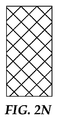
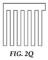
提供される剥離可能な接着剤物品は、それぞれがその内部に幅を有する複数のスリットのうちの少なくとも1つを有する形状記憶ポリマーシートを含んでもよい。スリットは、ナイフ、ダイ、レーザー、又はポリマーシートを切断するのに周知の任意のその他物品を用いて切断することにより、形状記憶ポリマーシート内に導入できる。スリットは、任意の形状であってよく、シート外辺部内で開始し終了してもよく、又はシート外辺部の1つ以上の末端を超えて延びてもよい。代表的なスリットパターンを図2A〜2Rに示す。図2A及び2Bは、1つの外辺縁部に平行で、一方の外辺縁部から対向する外辺縁部まで通るスリットの図である。図2C〜2Fは、一方の外辺縁部から対向する外辺縁部まで、2つの方向に延びる直線に囲まれた直交平行パターンを含むスリットパターンの図である。図2Gは、らせん状連続スリットを示す。図2Hは、同心性方形スリットを示す。図2Iは、穿孔として働き、1つの外辺縁部に平行で、一方の外辺縁部から対向する外辺縁部まで通る一連の整列したスリットを示す。図2Jは、2つの対向する外辺部に向かって、そこから延びるスリットパターンの図である。図2K及び2Lは、一方の外辺部から別の外辺部に延びる斜め方向スリットを示す。図2M〜2Pは、平行外辺部−外辺部スリット(図2M)、斜め方向外辺部−外辺部スリット(図2N)、及び直線に囲まれた外辺部−外辺部スリット(図2O及び2P)を含む、形状記憶ポリマーのロール上のスリットパターンを示す。形状記憶ポリマーフィルムは、図2Q及び図2Rに示されるくし状パターンで見られるものなど、幅を有するスリットを有してもよく、互いに強く接着しない接着剤層で特に有用である。上述のように、これらのパターンでは、接着剤が互いに強く接着しない場合を除いて、スリットの幅は上部に配置された接着剤の厚さを超えてはならない。第1の複数のスリットの全長は、歪んだ一時的な形状にある形状記憶ポリマーシートの面積の平方cmあたり、少なくとも0.35cmのスリット長をもたらすのに十分長さである。用語「スリット長」は、形状記憶ポリマーシート中の開口部、つまりスリットの最長寸法を表す。「全スリット長」は、形状記憶ポリマーシート中の複数のスリット長の合計である。 The provided peelable adhesive article may comprise a shape memory polymer sheet having at least one of a plurality of slits each having a width therein. The slit can be introduced into the shape memory polymer sheet by cutting using a knife, die, laser, or any other article known to cut polymer sheets. The slit may be of any shape, may begin and end within the sheet perimeter, or may extend beyond one or more ends of the sheet perimeter. A typical slit pattern is shown in FIGS. 2A and 2B are diagrams of a slit that is parallel to one outer edge and passes from one outer edge to the opposite outer edge. 2C to 2F are diagrams of slit patterns including orthogonal parallel patterns surrounded by straight lines extending in two directions from one outer edge to the opposite outer edge. FIG. 2G shows a spiral continuous slit. FIG. 2H shows a concentric square slit. FIG. 2I shows a series of aligned slits that act as perforations and run parallel to one outer edge and run from one outer edge to the opposite outer edge. FIG. 2J is a diagram of a slit pattern extending from two opposing outer edges. 2K and 2L show diagonal slits extending from one outer edge to another outer edge. 2M to 2P are a parallel outer side-outer side slit (FIG. 2M), an oblique outer side-outer side slit (FIG. 2N), and an outer side-outer side slit surrounded by a straight line ( FIG. 2 shows a slit pattern on a roll of shape memory polymer, including FIGS. 2O and 2P). Shape memory polymer films may have slits with widths, such as those seen in the comb-like patterns shown in FIGS. 2Q and 2R, and are particularly useful with adhesive layers that do not adhere strongly to each other. As mentioned above, in these patterns, the width of the slit must not exceed the thickness of the adhesive placed on top, unless the adhesives do not adhere strongly to each other. The overall length of the first plurality of slits is long enough to provide a slit length of at least 0.35 cm per square centimeter of area of the shape memory polymer sheet in a distorted temporary shape. The term “slit length” refers to the longest dimension of an opening in the shape memory polymer sheet, ie the slit. “Total slit length” is the total of a plurality of slit lengths in the shape memory polymer sheet.
典型的には、形状記憶ポリマーシートの面積に対する複数のスリットの全長(つまり、全スリット長)の割合は、0.35cm/cm2を超える。この割合は、約0.40cm/cm2超、約1.0cm/cm2超、又は更にそれ以上であってもよい。 Typically, the ratio of the total length of the plurality of slits (ie, the total slit length) to the area of the shape memory polymer sheet exceeds 0.35 cm / cm 2 . This proportion is about 0.40 cm / cm 2, greater than about 1.0 cm / cm 2 greater, or even may be greater.
提供される剥離可能な接着剤物品の製造方法の一実施形態を、図3に模式的に示す。複数のスリットを含む形状記憶ポリマーシート306の第2の対向する面が、キャリアシート301上に配置される。キャリアシート301は、スリット付け、及び接着剤コーティング又は積層の間、形状記憶ポリマーシート306を保持できる任意のシートであってもよい。一実施形態では、キャリアシート301は、ポリウレタン発泡テープである。例示した実施形態では、形状記憶ポリマーシート306の第1の対向する面は、コロナ処理305によって表面改質される。続いて、第1接着剤304aが、形状記憶ポリマーシート306の表面改質された第1の対向する面上に配置される。第1接着剤304aは、適用される接着剤が形状記憶ポリマーを弛緩させる温度を有さない限りは、溶媒型接着剤として、又は無溶媒接着剤として、当業者に周知の任意のコーティング法を用いて、形状記憶ポリマーシート306上に直接コーティングしてもよい。あるいは、第1接着剤304aを転写テープ(事前の工程で犠牲ライナー上にコーティングされている、又は転写テープとして購入した)として適用してもよい。所望の場合、転写前又は後に第1接着剤304aを架橋してもよい。
One embodiment of a method for producing the provided peelable adhesive article is schematically illustrated in FIG. A second opposing surface of the shape
次に、キャリア301を除き、図3に示すように、物品を裏返しにする。続いて、形状記憶ポリマーシート306の第2面を、模式図に示すように再びコロナ処理305によって表面改質し、その後第2接着剤304bをコーティング又は積層して、図3のスキームの最終に示す物品をもたらし、このとき、形状記憶ポリマーシート306の一方の面が第1接着剤304aで、及び第2面が第2接着剤304bでコーティングされている。その後、接着剤物品を第1基材及び第2基材に積層し、図4Bの最初の模式図に示す、提供される剥離可能な接着剤物品を形成する。
Next, the
接着剤物品の剥離方法も提供される。提供される方法の実施形態は、図4A及び4Bに模式的に示される。図4Aの左側は、提供される剥離可能な接着剤物品の分解斜視図である。この図は、複数のスリットを含む形状記憶ポリマーシート406を、形状記憶ポリマーシート406の第1の対向する表面上に配置される第1接着剤404aと共に示しており、その上部に第1基材402aが配置される。この図は、形状記憶ポリマー406の第2の対向する表面上に配置され、第2基材402bに接する第2接着剤404bも示している。図4Aの右側は、形状記憶ポリマーシート406の転移温度範囲を超えて加熱した後の同物品である。加熱すると、形状記憶ポリマーシート406はシートの平面方向に収縮し、垂直方向に膨張して、408に示すようにポリマーの小ブロックを形成する。
A method for peeling an adhesive article is also provided. An embodiment of the provided method is schematically illustrated in FIGS. 4A and 4B. The left side of FIG. 4A is an exploded perspective view of the provided peelable adhesive article. This figure shows a shape
例えば、CORTUFF又はSHRINKBOXなどのポリエチレンベースのものなどの一部の形状記憶ポリマー材料では、その形状記憶転移温度範囲を下回る温度まで非拘束状態で加熱し、材料をアニールさせることによって、ポリマーの熱形状変化特性を変えることが可能である。これにより、ポリマーの一時的な形状をより低度に歪んだ形状に変えることができるが、ポリマーの固有形状に実質的に影響しない。また、アニーリング温度を下回り、かつ形状記憶転移温度範囲を下回る温度において、ポリマーが自発的で小規模な形状変化を起こすことも予防する。図5は、CORTUFFフィルムのこの挙動を示す。図5の濃い線は、未アニールのCORTUFFフィルムの形状変化を示す。この線では、形状記憶転移温度範囲は、プロット線の傾きが最も大きい付近であり、この転移温度範囲をはるかに下回る温度で長さが徐々に変化していることが示される。反対に、明るいプロット線は、その転移温度範囲をわずかに下回った温度でアニール済みのCORTUFFフィルムの挙動を示す。この場合、転移温度範囲は、未アニールのフィルムの場合と実質的に同じであるが、転移温度範囲付近の温度まで長さの大幅な変化がない。 For example, in some shape memory polymer materials such as those based on polyethylene such as CORTUFF or SHRINKBOX, the thermal shape of the polymer can be obtained by heating unconstrained to a temperature below its shape memory transition temperature range and annealing the material. It is possible to change the change characteristics. This can change the temporary shape of the polymer to a less distorted shape, but does not substantially affect the inherent shape of the polymer. It also prevents the polymer from undergoing spontaneous and small-scale shape changes at temperatures below the annealing temperature and below the shape memory transition temperature range. FIG. 5 shows this behavior of CORTUFF film. The dark line in FIG. 5 shows the shape change of the unannealed CORTUFF film. This line shows that the shape memory transition temperature range is in the vicinity of the largest slope of the plot line, and the length gradually changes at a temperature far below this transition temperature range. Conversely, the bright plot lines show the behavior of CORTUFF films that have been annealed at temperatures slightly below their transition temperature range. In this case, the transition temperature range is substantially the same as in the case of an unannealed film, but there is no significant change in length to a temperature near the transition temperature range.
第1接着剤及び第2接着剤の相互の接着力が乏しい、又はかなり相溶性が低いいくつかの実施形態では、接着剤の厚さより広いスリットを有することが可能である。例えば、各面に2種類の異なる非接着性の、又は相溶性が低い接着剤をコーティングした両面接着テープを、各接着剤の厚さより広いスリットを伴って使用できる。図2Q及び2Rは、両面粘着又は両面接着テープを伴って提供される剥離可能な接着剤物品で使用できるくし状構造である。 In some embodiments where the adhesive strength of the first adhesive and the second adhesive is poor or much less compatible, it is possible to have slits that are wider than the thickness of the adhesive. For example, a double-sided adhesive tape coated with two different non-adhesive or poorly compatible adhesives on each side can be used with slits wider than the thickness of each adhesive. Figures 2Q and 2R are comb-like structures that can be used in peelable adhesive articles provided with double-sided adhesive or double-sided adhesive tape.
別の実施形態では、スリットを含む形状記憶ポリマーシートを、片面のみ接着剤コーティングし、2つの隣接する基材間に突き合わせ継ぎ目を形成する使用が意図される。この場合、接着剤が片面にコーティングされていれば、突き合わせ継ぎ目は、転移温度範囲を超えて形状記憶ポリマーシートを加熱することによってなくすことができる。 In another embodiment, the use of a shape memory polymer sheet comprising slits is adhesively coated on only one side to form a butt seam between two adjacent substrates. In this case, if the adhesive is coated on one side, the butt seam can be eliminated by heating the shape memory polymer sheet beyond the transition temperature range.
本発明の目的及び利点は、以下の実施例によって更に例示されるが、これらの実施例において列挙された特定の材料及びその量は、他の諸条件及び詳細と同様に本発明を過度に制限するものと解釈されるべきではない。 The objects and advantages of the present invention are further illustrated by the following examples, but the specific materials and amounts listed in these examples do not unduly limit the present invention as well as other conditions and details. Should not be construed to do.
収縮フィルムのスリット付け及び多層フィルムの作製の一般手順
1/4インチ(6.35mm)の厚さのガラス板に、12インチ(305mm)の長さの3Mウレタンフォームテープ4016を積層し、その上面に、12インチ(305mm)の長さの3M POST−IT紙(POST−IT Craft Paper C8512と同等品)を積層し、最後に、12インチ(305mm)の長さの下塗り済み収縮フィルムを積層した。3Mウレタンフォームテープ4016及びPOST−IT紙はキャリアとして働き、一方、収縮フィルムは、かみそり刃を用いて所定のパターンにスリット付けした。次に、感圧接着剤(PSA)テープ層を、スリット収縮フィルム上に積層した。続いて、収縮フィルム及びPSA積層体を90°の角度で剥がし、POST−IT紙及びウレタンフォームテープを残した。その後、収縮フィルムの露出面を別のPSAテープ層に積層した。
General procedure for slitting shrink film and making multilayer film 12M (305mm) length 3M urethane foam tape 4016 is laminated on 1/4 inch (6.35mm) thick glass plate and its top surface Was laminated with 12 inch (305 mm) long 3M POST-IT paper (equivalent to POST-IT Craft Paper C8512), and finally a 12 inch (305 mm) long primed shrink film was laminated. . 3M urethane foam tape 4016 and POST-IT paper served as carriers, while the shrink film was slit into a predetermined pattern using a razor blade. Next, a pressure sensitive adhesive (PSA) tape layer was laminated on the slit shrink film. Subsequently, the shrink film and the PSA laminate were peeled off at an angle of 90 ° to leave POST-IT paper and urethane foam tape. Thereafter, the exposed surface of the shrink film was laminated to another PSA tape layer.
90°剥離接着試験
収縮フィルムを含む多層テープの一方の面を、測定値75mm×125mm×1.5mmのステンレス鋼製クーポンに貼付した。別途記載のない限り、テープの測定値は25mm×100mmである。次に、測定値200mm×28mm×0.13mmの1片の陽極処理アルミホイル(Lawrence and Frederick(Streamwood,IL)から入手可能)を、多層テープの別の面に適用した。続いて、このアセンブリを、80℃で1時間、1.6N/cm2の圧力下のオーブンに置いた。その後、各サンプルセットから試料の一部を110℃のオーブンで30分間加熱し、別の試料を対照として試験するため未加熱のまま残した。室温まで冷却した後、試料を少なくとも24時間放置した。サンプルを、90°剥離一定角度取付け具に装着した後、1000Nロードセルを備えたInstron Model 4501ロードフレームを用いて、305mm/分の90°剥離モードで試験した。25mm〜75mmの剥離変位による抵抗力の値を平均し、剥離強度値とした。
90 ° Peel Adhesion Test One surface of the multilayer tape including the shrink film was attached to a stainless steel coupon having a measured value of 75 mm × 125 mm × 1.5 mm. Unless otherwise stated, the measured value of the tape is 25 mm × 100 mm. Next, a piece of anodized aluminum foil (available from Lawrence and Frederick, Streamwood, IL) with measurements 200 mm x 28 mm x 0.13 mm was applied to the other side of the multilayer tape. Subsequently, the assembly was placed in an oven under a pressure of 1.6 N / cm 2 at 80 ° C. for 1 hour. A portion of the sample from each sample set was then heated in an oven at 110 ° C. for 30 minutes and left unheated to test another sample as a control. After cooling to room temperature, the sample was left for at least 24 hours. Samples were tested in 90 ° peel mode at 305 mm / min using an Instron Model 4501 load frame equipped with a 1000 N load cell after mounting on a 90 ° peel constant angle fixture. The resistance values due to the peeling displacement of 25 mm to 75 mm were averaged to obtain a peeling strength value.
垂直引張接着試験
試験基材は、測定値25mm×64mmの基部を有するT字形のアルミニウム片とした。本発明の多層フィルムを各アルミニウム基材の基部の中央部に接触させることによって、この2枚の基材を互いに接着した。別途記載のない限り、各テープ片の測定値は25mm×25mmであり、テープ設計ごとに8つの試料を作製した。接着後、試料を23℃及び相対湿度50%の環境中に24時間放置した。その後、試料のうち4つを、110℃のオーブンで30分間加熱した。更に24時間後、8つのサンプル全てについて、1000lbf(4448.2N)のロードセルを備えるSintechロードフレームにおいて、垂直引張モード、51mm/分の速度で、室温における破損を試験した。未加熱の試料の平均ピーク荷重、及び加熱サンプルの平均ピーク荷重をそれぞれ算出した。
Vertical tensile adhesion test The test substrate was a T-shaped aluminum piece having a base with a measured value of 25 mm x 64 mm. The two substrates were bonded to each other by bringing the multilayer film of the present invention into contact with the central portion of the base of each aluminum substrate. Unless otherwise stated, the measured value of each tape piece was 25 mm × 25 mm, and eight samples were prepared for each tape design. After bonding, the sample was left in an environment of 23 ° C. and 50% relative humidity for 24 hours. Thereafter, four of the samples were heated in an oven at 110 ° C. for 30 minutes. After an additional 24 hours, all 8 samples were tested for breakage at room temperature in a Sintech load frame with a 1000 lbf (4448.2N) load cell at a rate of 51 mm / min in vertical tension mode. The average peak load of the unheated sample and the average peak load of the heated sample were calculated respectively.
接着面積測定の一般方法
加熱したサンプルの接着試験の後、収縮フィルムの露出部分を、ペンを用いて黒インク又は蛍光黄色インクで着色した。続いて、黒インクの場合、可視光線下でサンプルの写真を撮り、蛍光インクの場合、紫外線下でサンプルの写真を撮った。テープ片のサイズを画定する方形区域内の画素数を測定し、黒又は蛍光のいずれかにインク付けされた画素数を測定することによって、画像ファイルを解析した。その後、インク付け領域内の画素数を初期のテープ領域の画素数で割った比を用いて、接着面積を画定した。
General method of adhesion area measurement After the adhesion test of the heated sample, the exposed portion of the shrink film was colored with black ink or fluorescent yellow ink using a pen. Subsequently, in the case of black ink, a sample photograph was taken under visible light, and in the case of fluorescent ink, a sample photograph was taken under ultraviolet light. The image file was analyzed by measuring the number of pixels in the square area defining the size of the tape strip and measuring the number of pixels inked in either black or fluorescent. Thereafter, the adhesion area was defined using the ratio of the number of pixels in the inked area divided by the number of pixels in the initial tape area.
(実施例1)
160mm幅のCORTUFF 200(Sealed Air Corporation(Duncan,SC)の厚さ51μmのポリエチレン収縮フィルム)のロールを、2.0J/cm2で窒素コロナ処理した。18インチ(460mm)の部分を、#8メイヤーロッドを用いて、トルエン中3固体%の濃度の3M Tape Primer 94の溶液で下塗りし、80℃で1時間乾燥した。サンプルの一部を、長さ方向に1.6mm幅、横方向に6.4mm幅のストリップにスリット付けし、矩形を作り出した。4インチ(102mm)の長さの1インチ幅(25.4mm)の3M VHBテープRP16を、処理済みCORTUFFフィルムの両面に積層した。90°剥離接着試験を用いて得られたアセンブリを試験した結果を以下で報告する。
Example 1
A roll of 160 mm wide CORTUFF 200 (Sealed Air Corporation (Duncan, SC) 51 μm thick polyethylene shrink film) was nitrogen corona treated at 2.0 J / cm 2 . An 18 inch (460 mm) portion was primed with a solution of 3M Tape Primer 94 at a concentration of 3% solids in toluene using a # 8 Mayer rod and dried at 80 ° C. for 1 hour. A portion of the sample was slit into strips that were 1.6 mm wide in the length direction and 6.4 mm wide in the transverse direction to create a rectangle. 4 inch (102 mm) long 1 inch wide (25.4 mm) 3M VHB tape RP16 was laminated to both sides of the treated CORTUFF film. The results of testing the assembly obtained using the 90 ° peel adhesion test are reported below.
(実施例2)
457mm×160mmの部分のCORTUFFフィルム(2.0J/cm2で窒素コロナ処理を行った)を、#8メイヤーロッドを用いて、3固体%の濃度の3M接着プロモーターN200Jで下塗りし、80℃で1時間乾燥した。サンプルの一部を各方向(長さ方向及び横方向)にスリット付けし、片面に3.6mmの正方形を作り出した。収縮フィルムを、3M VHBテープ5930とDS4転写テープとの間に積層した。次に、サンプルを90°剥離接着試験を用いて試験した結果を、以下に示す。
(Example 2)
A 457 mm × 160 mm portion of CORTUFF film (nitrogen corona treated at 2.0 J / cm 2 ) was primed with 3M adhesion promoter N200J at a concentration of 3% solids using a # 8 Meyer rod at 80 ° C. Dried for 1 hour. A portion of the sample was slit in each direction (longitudinal and transverse) to create a 3.6 mm square on one side. The shrink film was laminated between 3M VHB tape 5930 and DS4 transfer tape. Next, the results of testing the sample using the 90 ° peel adhesion test are shown below.

(実施例3)
CORTUFF 200フィルムの両面を、手持ち式コロナ処理機(Electro−Technic Products Inc.(Chicago,IL)、BD−20AC、Laboratory Corona Treater、ラインフィルター115V)で処理し、各方向(長さ方向及び横方向)にスリット付けして、片面に3.6mmの正方形を作り出した。スリット付き収縮フィルムを、3M COMMANDストリップ17021P、ミディアム、白色(54mm幅)と3M熱導電性テープ8815(54mm幅)との間に積層した。次に、得られた構成体を用いて、4枚の三角形のセラミックスタイル(1辺54mm)を、鋼にCOMMAND接着剤が付いている鋼製プレートに付着させた。接着後、試料を23℃及び相対湿度50%の環境中に24時間放置した。プロパンバーナーをタイル中央部に30秒間保持し、その時、タイルの外側面は120℃であった。この時、隣接する(未加熱の)タイルは、30〜65℃に達するのみであった。続いて、タイルを4時間冷却し、その後、垂直引張モード、51mm/分の速度で除去し、ピーク荷重は21Nであった。サンプルは、CORTUFF/COMMAND境界面で剥離され、続いてCOMMAND層は、手によって鋼からきれいに剥がれた。隣接する(未加熱の)タイルの平均ピーク荷重は、垂直引張モードにおいて360Nであり、COMMAND/鋼境界面において破損した。
Example 3
Both sides of the CORTUFF 200 film are processed with a hand-held corona processor (Electro-Technical Products Inc. (Chicago, IL), BD-20AC, Laboratory Corona Treater, line filter 115V) in each direction (longitudinal and lateral directions). ) To create a 3.6 mm square on one side. A slit shrink film was laminated between 3M COMMAND strip 17021P, medium, white (54 mm width) and 3M thermally conductive tape 8815 (54 mm width). The resulting construction was then used to attach four triangular ceramic styles (54 mm per side) to a steel plate with COMMAND adhesive on the steel. After bonding, the sample was left in an environment of 23 ° C. and 50% relative humidity for 24 hours. The propane burner was held in the center of the tile for 30 seconds, at which time the outer surface of the tile was 120 ° C. At this time, adjacent (unheated) tiles only reached 30-65 ° C. Subsequently, the tile was cooled for 4 hours and then removed at a rate of 51 mm / min in the vertical tension mode, and the peak load was 21N. The sample was peeled off at the CORTUFF / COMMAND interface, and then the COMMAND layer was peeled clean from the steel by hand. The average peak load of adjacent (unheated) tiles was 360 N in the vertical tension mode and failed at the COMMAND / steel interface.
(実施例4)
457mm×160mmの部分のCORTUFFフィルム(2.0J/cm2で窒素コロナ処理を行った)を、#20メイヤーロッドを用いて、1.5固体%の濃度でコーティングされた3M接着プロモーターN200Jで下塗りし、80℃で1時間乾燥した。コロナ処理かつ下塗り済みのCORTUFFフィルム層の一部を、図2Aに示すように、長さ方向に、2本の0.5インチのストリップにスリット付けした。垂直引張接着試験を用いてテープを試験し、加熱済み及び未加熱のサンプルの平均ピーク荷重について以下に報告する。
Example 4
A 457 mm × 160 mm portion of CORTUFF film (nitrogen corona treated at 2.0 J / cm 2 ) was primed with 3M adhesion promoter N200J coated at a concentration of 1.5 solids% using a # 20 Meyer rod. And dried at 80 ° C. for 1 hour. A portion of the corona-treated and primed CORTUFF film layer was slit into two 0.5 inch strips in the length direction, as shown in FIG. 2A. The tape is tested using the vertical tensile adhesion test and reported below for the average peak load of the heated and unheated samples.
比較例1
CORTUFF層にスリット付けしなかった以外は、実施例4に記載のように比較例1を組み立てて試験した。
Comparative Example 1
Comparative Example 1 was assembled and tested as described in Example 4 except that the CORTUFF layer was not slit.
(実施例5)
図2Bに示すように、CORTUFF層を、長さ方向に7本の3.56mmのストリップにスリット付けした以外は、実施例4に記載のように実施例5を組み立てて試験した。
(Example 5)
As shown in FIG. 2B, Example 5 was assembled and tested as described in Example 4 except that the CORTUFF layer was slit into seven 3.56 mm strips in the lengthwise direction.
(実施例6)
図2Cに示すように、CORTUFF層を、各方向(長さ方向及び横方向)のストリップにスリット付けし、片面に6.35mmの正方形を作り出した以外は、実施例4に記載のように実施例6を組み立てて試験した。
(Example 6)
As shown in FIG. 2C, the CORTUFF layer was performed as described in Example 4 except that the strips in each direction (longitudinal and transverse) were slit to create a 6.35 mm square on one side. Example 6 was assembled and tested.
(実施例7)
図2Dに示すように、CORTUFF層を、各方向(長さ方向及び横方向)のストリップにスリット付けし、片面に3.56mmの正方形を作り出した以外は、実施例4に記載のように実施例7を組み立てて試験した。
(Example 7)
As shown in FIG. 2D, the CORTUFF layer was performed as described in Example 4 except that the strips in each direction (longitudinal and transverse) were slit to create a 3.56 mm square on one side. Example 7 was assembled and tested.
(実施例8)
図2Eに示すように、CORTUFF層を、長さ方向に1.6mm幅、横方向に3.2mm幅のストリップにスリット付けし、矩形を作り出した以外は、実施例4に記載のように実施例8を組み立てて試験した。
(Example 8)
As shown in FIG. 2E, the CORTUFF layer was performed as described in Example 4 except that it was slit into strips that were 1.6 mm wide and 3.2 mm wide in the transverse direction to create a rectangle. Example 8 was assembled and tested.
(実施例9)
図2Fに示すように、CORTUFF層を、各方向(長さ方向及び横方向)に1.6mm幅のストリップにスリット付けし、片面に1.6mmの正方形を作り出した以外は、実施例4に記載のように実施例9を組み立てて試験した。
Example 9
As shown in FIG. 2F, Example 4 except that the CORTUFF layer was slit into 1.6 mm wide strips in each direction (longitudinal and lateral directions) to create a 1.6 mm square on one side. Example 9 was assembled and tested as described.
(実施例10)
図2Gに示すように、CORTUFF層を、4.24mm幅の単一の連続らせん状パターンのストリップにスリット付けした以外は、実施例4に記載のように実施例10を組み立てた。2つの未加熱のサンプルは、垂直引張接着について試験し、110℃に加熱した2つのサンプルは、垂直接着について試験し、表2に結果を示す。
(Example 10)
As shown in FIG. 2G, Example 10 was assembled as described in Example 4 except that the CORTUFF layer was slit into a single continuous spiral pattern strip of 4.24 mm width. Two unheated samples were tested for vertical tensile adhesion and two samples heated to 110 ° C. were tested for vertical adhesion and the results are shown in Table 2.
(実施例11)
図2Hに示すように、CORTUFF層を、各連続的正方形の縁部間が2.12mmである、同心性正方形にスリット付けした以外は、実施例4に記載のように実施例7を組み立てた。2つの未加熱のサンプルは、垂直引張接着について試験し、110℃に加熱した2つのサンプルは、垂直接着について試験し、表2に結果を示す。
(Example 11)
As shown in FIG. 2H, Example 7 was assembled as described in Example 4 except that the CORTUFF layer was slit into concentric squares with 2.12 mm between the edges of each continuous square. . Two unheated samples were tested for vertical tensile adhesion and two samples heated to 110 ° C. were tested for vertical adhesion and the results are shown in Table 2.
(実施例12)
図2Iに示すように、CORTUFF層を穿孔し、クロスウェブ方向に1.59mm幅の非連続スリットを形成した以外は、実施例4に記載のように実施例12を組み立てた。各スリットの列において、全長の少なくとも半分を穿孔した。2つの未加熱のサンプルは、垂直引張接着について試験し、110℃に加熱した2つのサンプルは、垂直接着について試験し、表2に結果を示す。
(Example 12)
As shown in FIG. 2I, Example 12 was assembled as described in Example 4 except that the CORTUFF layer was perforated to form a 1.59 mm wide discontinuous slit in the crossweb direction. In each row of slits, at least half of the total length was drilled. Two unheated samples were tested for vertical tensile adhesion and two samples heated to 110 ° C. were tested for vertical adhesion and the results are shown in Table 2.
実施例4〜11及び比較例1のそれぞれについて、110℃に曝露後の張力接着を上記のように測定した後、形状記憶ポリマーシート(CORTUFF)によって覆われる接着剤の面積を、覆われた接着剤の割合として測定した。更に、アニール後の、形状記憶ポリマーシートの未収縮の初期面積あたりの、初期、未収縮のスリットの全長を算出した。データを表2に示す。収縮フィルムにスリット付けすると、加熱後の接着面積が小さくなり、それに応じた接着レベルの低下をもたらす。 For each of Examples 4-11 and Comparative Example 1, after measuring the tensile adhesion after exposure to 110 ° C. as described above, the area of the adhesive covered by the shape memory polymer sheet (CORTUFFF) was determined as the covered adhesion. It was measured as the ratio of the agent. Furthermore, the total length of the initial and non-shrinkage slits per non-shrinkage initial area of the shape memory polymer sheet after annealing was calculated. The data is shown in Table 2. When the shrink film is slit, the adhesion area after heating is reduced, and the adhesion level is lowered accordingly.
(実施例13)
熱可塑性ポリウレタン樹脂のペレット、DiARY MM3520(18.75g)及びDiARY MM9020(6.25g)(共にSMP Technologies,Inc.(Tokyo,Japan)から入手可能)を、Brabenderミキサー(C.W.Brabender Instruments,Inc.(South Hackensack,NJ)のPrep Center Type D−51)内で、5分間、180℃で混合した。得られたポリマーを、146℃の液圧プレス(Carver Inc.(Wabash,IN)のModel 2699)で加圧してシートにし、0.7mm厚のフィルムにした。このフィルム片25mm×63mmを、70℃のオーブンで15分間加熱し、伸張率180%まで手で引き延ばした。得られたストリップの幅は15mm、厚さは0.5mmであった。図2Jに示すように、スリットがストリップの長さと直交し、6mm間隔で離れるように、ストリップの各縁部に沿って長さ7mmのスリットを作製した。フィルムの対向する縁部のスリットは、2mmオフセットした。VHB RP16発泡テープを、フィルムの両面に積層した。続いて、このフィルムを、長さがそれぞれ25mmの4つの部分に切断し、これらの部分を用いて垂直引張接着試験を実施した。4つの試料のうち2つは50℃で30分間加熱し、別の2つは未加熱のままとした。未加熱の試料は、70N/cm2の平均接着力を示し、加熱試料は、34N/cm2の平均接着力を示した。接着剤の痕跡上を測定するとき、加熱サンプルの接着面積は、元の値の57%に減少した。
(Example 13)
Thermoplastic polyurethane resin pellets, DiARY MM3520 (18.75 g) and DiARY MM9020 (6.25 g) (both available from SMP Technologies, Inc. (Tokyo, Japan)), Brabender mixer (C. Brabender Instruments). Inc. (South Hackensack, NJ) Prep Center Type D-51) for 5 minutes at 180 ° C. The resulting polymer was pressed into a sheet by a hydraulic press at 146 ° C. (Model 2699, Carver Inc. (Wabash, Ind.)) Into a 0.7 mm thick film. This film piece 25 mm × 63 mm was heated in an oven at 70 ° C. for 15 minutes and stretched by hand to an elongation of 180%. The obtained strip had a width of 15 mm and a thickness of 0.5 mm. As shown in FIG. 2J, 7 mm long slits were made along each edge of the strip so that the slits were orthogonal to the strip length and separated by 6 mm. The slits at the opposite edges of the film were offset by 2 mm. VHB RP16 foam tape was laminated on both sides of the film. Subsequently, the film was cut into four portions each having a length of 25 mm, and a vertical tensile adhesion test was performed using these portions. Two of the four samples were heated at 50 ° C. for 30 minutes and the other two were left unheated. Unheated samples showed an average adhesion strength of 70N / cm 2, heating samples showed an average adhesion strength of 34N / cm 2. When measured on the adhesive trace, the bonded area of the heated sample was reduced to 57% of the original value.
(実施例14)
実施例4で用いたものと同一の4インチ(102mm)の下塗り済み収縮フィルムを、図2Qに示すくし状パターンにスリット付けした。1/2インチ(12.7mm)幅の3M SCOTCH Permanent Double−Sided Tape 137の2枚の平行ストリップを、テープの外側を収縮フィルムの一方の面に接着させた状態で、スリット付けした収縮フィルムに積層した。次いで、収縮フィルムの対向する面を、SCOTCH両面テープの2枚の平行ストリップの内側に積層した。続いて、組立品全体を、5×2.5cmの2枚のストリップに切断し、底部を清浄なステンレス鋼製プレートに、上部を陽極処理アルミニウムの8インチ(203mm)のストリップに接着した。接着後、試料を23℃及び相対湿度50%の環境中に24時間放置した。その後、試料のうち1つを、110℃のオーブンで30分間加熱した。更に24時間後、両方のサンプルについて、1000Nのロードセルを備えるInstronロードフレームにおいて、90°剥離モード、305mm/分の速度で、室温における破損を試験した。未加熱のサンプルの剥離力は、7.6N/cm幅であり、加熱サンプルの剥離力は、1.5N/cm幅であった。接着剤上の収縮フィルムの被覆面積は、収縮前は64%、収縮後は15%であった。
(Example 14)
The same 4 inch (102 mm) primed shrink film used in Example 4 was slit into the comb pattern shown in FIG. 2Q. Apply two parallel strips of 1/2 inch (12.7 mm) wide 3M SCOTCH Permanent Double-Sided Tape 137 to the slitted shrink film with the outside of the tape adhered to one side of the shrink film. Laminated. The opposing sides of the shrink film were then laminated inside the two parallel strips of SCOTCH double-sided tape. The entire assembly was then cut into two 5 × 2.5 cm strips, with the bottom bonded to a clean stainless steel plate and the top bonded to an 8 inch (203 mm) strip of anodized aluminum. After bonding, the sample was left in an environment of 23 ° C. and 50% relative humidity for 24 hours. Thereafter, one of the samples was heated in an oven at 110 ° C. for 30 minutes. After an additional 24 hours, both samples were tested for breakage at room temperature in an Instron load frame with a 1000 N load cell at 90 ° peel mode and 305 mm / min. The peel force of the unheated sample was 7.6 N / cm width, and the peel force of the heated sample was 1.5 N / cm width. The area covered by the shrink film on the adhesive was 64% before shrinkage and 15% after shrinkage.
(実施例15)
図2Rに示すように、CORTUFF層を分枝状パターンにスリット付けした以外は、実施例14に記載のように実施例15を組み立てて試験した。未加熱のサンプルの剥離力は、5.3N/cm幅であり、加熱サンプルの剥離力は、0.96N/cm幅であった。接着剤上の収縮フィルムの被覆面積は、収縮前は64%、収縮後は15%であった。
(Example 15)
As shown in FIG. 2R, Example 15 was assembled and tested as described in Example 14, except that the CORTUFF layer was slit into a branched pattern. The peel force of the unheated sample was 5.3 N / cm width, and the peel force of the heated sample was 0.96 N / cm width. The area covered by the shrink film on the adhesive was 64% before shrinkage and 15% after shrinkage.
(実施例16)
CORTUFF 200フィルムを、Urethane Foam Tape 4008の厚さ3.2mm、幅2.54cmのストリップに積層した。続いて、CORTUFFフィルムを、手持ち式コロナ処理機(Electro−Technic Products Inc.(Chicago,IL)、BD−20AC、Laboratory Corona Treater、ラインフィルター115V)で処理した。その後、CORTUFFフィルムを、各方向(長さ方向及び横方向)に、1インチあたり7枚のストリップ(1cmあたり2.8枚のストリップ)に薄く切り、片面に3.56mmの正方形を作り出した。厚さ0.38mm×幅2.54cmのVHB 4920(3M Corporationから入手可能)を、処理済みのCORTUFFに積層し、0.7N/cm2の圧力下で45分間置いた。次に、VHBをウレタンテープから剥がし、CORTUFFが、ウレタンテープよりもVHBに接着していることを確認した。続いて、CORTUFFの別の面をコロナ処理し、VHB 4920の第2層をそれに対して積層した。
(Example 16)
CORTUFF 200 film was laminated to a strip of Urethane Foam Tape 4008 3.2 mm thick and 2.54 cm wide. Subsequently, the CORTUFF film was processed with a hand-held corona processor (Electro-Technical Products Inc. (Chicago, IL), BD-20AC, Laboratory Corona Treater, line filter 115V). The CORTUFF film was then sliced into 7 strips per inch (2.8 strips per cm) in each direction (longitudinal and transverse) to create a 3.56 mm square on one side. VHB 4920 (available from 3M Corporation) 0.38 mm thick x 2.54 cm wide was laminated to the treated CORTUFF and placed under a pressure of 0.7 N / cm 2 for 45 minutes. Next, VHB was peeled off from the urethane tape, and it was confirmed that CORTUFF was adhered to VHB rather than urethane tape. Subsequently, another side of CORTUFF was corona treated and a second layer of VHB 4920 was laminated to it.
得られた多層テープを垂直引張試験にかけた。全ての試料が、VHBテープの一方と熱収縮フィルムとの間の境界面で破損した。未加熱のサンプルの平均ピーク荷重は、124N/cm2であり、加熱サンプルの平均ピーク荷重は、20N/cm2であった。加熱したサンプルより破損試料を写真に撮ると、収縮したCORTUFFによって覆われた平均面積が、VHBによって覆われた面積の23%であることが判明した。 The resulting multilayer tape was subjected to a vertical tensile test. All samples failed at the interface between one of the VHB tapes and the heat shrink film. The average peak load of a sample of unheated is 124N / cm 2, the average peak load of heating samples was 20 N / cm 2. Taking a photograph of the damaged specimen from the heated sample revealed that the average area covered by the shrinking CORTUFF was 23% of the area covered by VHB.
実施例17〜22の試験
実施例17〜22は、上記の垂直引張接着試験方法を変更して試験した。各テープ設計より5つの試料を110℃に加熱し、加熱中、各試料に1kg重量の荷重をかけ、加熱中に垂直圧縮力を加えた。
Tests of Examples 17-22 Examples 17-22 were tested by modifying the above vertical tensile adhesion test method. Five samples from each tape design were heated to 110 ° C., a 1 kg weight load was applied to each sample during heating, and a vertical compression force was applied during heating.
(実施例17)
図2Kに示すように、CORTUFF層を、長さ方向に45°のピッチで13mmのストリップをスリット付けした以外は、実施例16に従って物品を作製した。
(Example 17)
As shown in FIG. 2K, an article was made according to Example 16 except that the CORTUFF layer was slit with a 13 mm strip at a 45 ° pitch in the length direction.
比較例2
CORTUFF層をスリット付けしなかった以外は、実施例17に従って物品を作製した。
Comparative Example 2
Articles were made according to Example 17 except that the CORTUFF layer was not slit.
(実施例18)
図2Lに示すように、CORTUFF層を、長さ方向に45°のピッチで6.4mm幅のストリップをスリット付けした以外は、実施例16に従って物品を作製した。
(Example 18)
As shown in FIG. 2L, an article was prepared according to Example 16 except that the CORTUFF layer was slit with a strip of 6.4 mm width at a 45 ° pitch in the length direction.
(実施例19)
図2Mに示すように、CORTUFF層を、長さ方向に3.6mm幅にスリット付けした以外は、実施例16に従って物品を作製した。
(Example 19)
As shown in FIG. 2M, an article was made according to Example 16 except that the CORTUFF layer was slit in the length direction to a width of 3.6 mm.
(実施例20)
図2Nに示すように、CORTUFF層を、長さ方向に+45°及び−45°のピッチで6.4mm幅のストリップにスリット付けし、片面に6.4mmの正方形を作り出した以外は、実施例16に従って物品を作製した。
(Example 20)
As shown in FIG. 2N, the CORTUFF layer was slit into 6.4 mm wide strips at + 45 ° and −45 ° pitches in the length direction to create a 6.4 mm square on one side. Articles were made according to 16.
(実施例21)
図2Pに示すように、CORTUFF層を、各方向(長さ方向及び横方向)に25mmあたり7枚のストリップにスリット付けし、片面に3.6mmの正方形を作り出した以外は、実施例16に従って物品を作製した。
(Example 21)
As shown in FIG. 2P, according to Example 16 except that the CORTUFF layer was slit into 7 strips per 25 mm in each direction (longitudinal and transverse) to create a 3.6 mm square on one side. Articles were made.
(実施例22)
図2Oに示すように、CORTUFF層を、各方向(長さ方向及び横方向)に25mmあたり14枚のストリップにスリット付けし、片面に1.8mmの正方形を作り出した以外は、実施例16に従って物品を作製した。
(Example 22)
As shown in FIG. 2O, according to Example 16 except that the CORTUFF layer was slit into 14 strips per 25 mm in each direction (longitudinal and transverse) to create a 1.8 mm square on one side. Articles were made.
実施例17〜22及び比較例2の垂直張力接着を試験した後、110℃に加熱したサンプルを、形状記憶ポリマーシート(CORTUFF)によって覆われる接着剤の面積を、覆われた接着剤の割合として解析した。更に、形状記憶ポリマーシート初期面積に対する比として、元のスリットの全長を算出した。データを表3に示す。収縮フィルムにスリット付けすると、加熱後の接着面積が小さくなり、それに応じた接着レベルの低下をもたらす。 After testing the vertical tension adhesion of Examples 17 to 22 and Comparative Example 2, the area of the adhesive covered with the shape memory polymer sheet (CARTUFFF) was measured for the sample heated to 110 ° C. as a percentage of the covered adhesive. Analyzed. Furthermore, the total length of the original slit was calculated as a ratio to the initial area of the shape memory polymer sheet. The data is shown in Table 3. When the shrink film is slit, the adhesion area after heating is reduced, and the adhesion level is lowered accordingly.
比較例3
CORTUFF 200収縮フィルムのサンプルの各面を、5J/cm2の量で窒素コロナ処理した。次に、サンプルの各面を、#20メイヤーロッドを用いて1.5固体%濃度のN200Jで下塗りし、80℃で1時間乾燥した。各面に、3.6mmの正方形のパターンをスリット付けし、一方の面をマスキングテープ(3M HIGHLAND 2727)に積層した。このフィルムを25mm×25mmの正方形に切断した。DP100エポキシ(3M)の層を、鋼製試験クーポン(Q−Lab Corporation(Cleveland,OH)のType「RS」Steel、102mm×25mm×1.6mm、Square Corners、Iron Phosphated(B−1000))の一方の末端部の25mm×25mmの領域に適用した。スリット付き収縮フィルムをエポキシ層に適用し、エポキシを2時間硬化させた。続いて、マスキングテープを収縮フィルムから剥がし、別のDP100エポキシの層を収縮フィルムの露出面に適用した。直径0.3mmのステンレス鋼製ワイヤ2本を、ボンドラインのスペーサとして、未硬化のエポキシ中に埋め込んだ。次に、追加の鋼製クーポンをエポキシの上面に置き、2つのダブルクリップで挟んで、重なり領域が25mm×25mmの重なり剪断試料を作製した。4つの試料を作製し、44時間硬化させた。その後、試料のうち2つを、110℃のオーブンに30分間置いた。サンプルを更に24時間室温で放置し、その後破損について試験した。自己引き締めグリップ及び20kNのロードセルを備えたSintechロードフレームを用いて、重なり剪断モードで試験を実施した。試験速度は2.5mm/分とした。未加熱のサンプルの平均ピーク荷重は2600Nであり、全てエポキシ/収縮フィルム境界面において最初に破損した。加熱したサンプルの平均ピーク荷重は4700Nであり、同様にエポキシ/収縮フィルム境界面において破損した。収縮フィルムの可視光線による収縮は起こらなかった。
Comparative Example 3
Each side of the CORTUFF 200 shrink film sample was nitrogen corona treated in an amount of 5 J / cm 2 . Next, each side of the sample was primed with 1.5% solids concentration N200J using a # 20 Mayer rod and dried at 80 ° C. for 1 hour. A 3.6 mm square pattern was slit on each side and one side was laminated to masking tape (3M HIGHLAND 2727). This film was cut into 25 mm × 25 mm squares. A layer of DP100 epoxy (3M) was applied to a steel test coupon (Type-RS Steel, Q-Lab Corporation (Cleveland, OH), 102 mm × 25 mm × 1.6 mm, Square Corners, Iron Phosphorated (B-1000)). It applied to the area | region of 25 mm x 25 mm of one terminal part. A slit shrink film was applied to the epoxy layer and the epoxy was allowed to cure for 2 hours. Subsequently, the masking tape was peeled from the shrink film and another DP100 epoxy layer was applied to the exposed surface of the shrink film. Two stainless steel wires with a diameter of 0.3 mm were embedded in uncured epoxy as bond line spacers. Next, an additional steel coupon was placed on top of the epoxy and sandwiched between two double clips to produce an overlap shear sample with an overlap area of 25 mm × 25 mm. Four samples were made and cured for 44 hours. Thereafter, two of the samples were placed in an oven at 110 ° C. for 30 minutes. Samples were left for an additional 24 hours at room temperature and then tested for breakage. Testing was performed in overlap shear mode using a Sintech load frame equipped with a self-tightening grip and a 20 kN load cell. The test speed was 2.5 mm / min. The average peak load of the unheated sample was 2600 N and all failed initially at the epoxy / shrink film interface. The average peak load of the heated sample was 4700 N and similarly failed at the epoxy / shrink film interface. Shrinkage of the shrink film by visible light did not occur.
準備的実施例1
長さ12インチ(305mm)×幅2インチ(51mm)の部分のCORTUFF熱収縮フィルム(厚さ50マイクロメートル、Sealed Air Corporation(Duncan,SC))を、POST−ITキャリア紙に付着させ、手回しクランク付き回転ダイ変換器を用いて、12.7mmのストリップにダイカットした。次に、サンプルを、約51mmの正方形にハサミで切り、手回しクランク付き回転ダイ変換器に戻して、片面に0.5インチ(12.7mm)の正方形を作り出した。その後、ダイカットした正方形は、任意の十分に強力な接着剤、又は機械的手段によって容易に除去され、剥離可能な境界面として使用できた。
Preparatory Example 1
A CORTUFF heat shrink film (thickness 50 micrometers, Sealed Air Corporation (Duncan, SC)) measuring 12 inches long (305 mm) x 2 inches wide (51 mm) is attached to POST-IT carrier paper and hand-cranked. Die cut into 12.7 mm strips using a rotary die converter with a tip. The sample was then cut into scissors about 51 mm square and returned to the rotating die converter with a hand crank to create a 0.5 inch (12.7 mm) square on one side. The die cut square was then easily removed by any sufficiently strong adhesive or mechanical means and could be used as a peelable interface.
(実施例23)
VHB 4920層のうち1つを、3M Thermally Conductive Tape 8810(25mm幅)の層に置き換えて積層した以外は、実施例16に従って物品を作製した。得られた多層テープを垂直引張試験にかけた。全ての試料が、Thermally Conductive Tapeの一方と熱収縮フィルムとの間の境界面で最初に破損した。未加熱のサンプルの平均垂直引張接着は、83N/cm2であり、加熱サンプルの平均ピーク荷重は、1.4N/cm2であった。加熱したサンプルより破損試料を写真に撮ると、収縮したCortuffによって覆われた平均面積が、VHBによって覆われた面積の10%であることが判明した。代表的な写真を図6に示すが、ここでは、収縮フィルムは固有形状で、黒インクによる濃い部分である。
(Example 23)
Articles were made according to Example 16 except that one of the VHB 4920 layers was replaced with a layer of 3M Thermally Conductive Tape 8810 (25 mm width). The resulting multilayer tape was subjected to a vertical tensile test. All samples first failed at the interface between one of the Thermally Conductive Tapes and the heat shrink film. The average vertical tensile adhesion of the unheated sample was 83 N / cm 2 and the average peak load of the heated sample was 1.4 N / cm 2 . Taking a photograph of the damaged specimen from the heated sample revealed that the average area covered by the contracted Cortuff was 10% of the area covered by VHB. A typical photograph is shown in FIG. 6. Here, the shrink film has a unique shape and is a dark portion with black ink.
本発明の態様による剥離可能な接着剤物品、並びにその製造方法及び使用方法の代表的な実施形態を以下に示す。 Exemplary embodiments of peelable adhesive articles according to aspects of the present invention, as well as methods of making and using the same, are shown below.
実施形態1は、歪んだ一時的な形状及び固有形状と第1及び第2の対向する表面とを有し、内部にそれぞれが幅を有する複数のスリットのうち少なくとも1つを含む領域を備え、この複数のスリットが全スリット長を画定し、そして、転移温度範囲以上に加熱されると、形状記憶シートがその歪んだ一時的な形状から固有形状に少なくとも部分的に変換される形状記憶ポリマーシートと、第1の厚さ、並びに第1及び第2の対向する表面を有し、第1接着剤が感圧接着剤を含み、そして、第1接着剤層の第1の対向する表面の大部分が、歪んだ一時的な形状にある形状記憶ポリマーシートの第1の対向する表面の大部分上に配置される、第1接着剤と、第2の厚さ、第1及び第2の対向する面を有し、第2接着剤の第1の対向する面の大部分が、歪んだ一時的な形状にある形状記憶ポリマーの第2の対向する面の大部分上に配置される、第2接着剤と、を備える、熱剥離可能な接着剤物品である。 Embodiment 1 includes a region including at least one of a plurality of slits each having a width, having a distorted temporary shape and a unique shape, and first and second opposing surfaces. The plurality of slits define a total slit length, and when heated above the transition temperature range, the shape memory polymer sheet is at least partially converted from its distorted temporary shape to an intrinsic shape. A first thickness, and first and second opposing surfaces, wherein the first adhesive includes a pressure sensitive adhesive, and the first opposing surface of the first adhesive layer is large. A first adhesive and a second thickness, a first and a second opposing portion, the portion being disposed on a majority of the first opposing surface of the shape memory polymer sheet in a distorted temporary shape Most of the first opposing surface of the second adhesive Are arranged on a substantial part of the second opposing surface of a shape memory polymer in a temporary shape distorted comprises a second adhesive, and a heat-releasable adhesive article.
実施形態2は、形状記憶ポリマーシートが2軸配向であり、一方向に最大収縮張力を有する、実施形態1に記載の熱剥離可能な接着剤物品である。 Embodiment 2 is a heat-peelable adhesive article according to embodiment 1, wherein the shape memory polymer sheet is biaxially oriented and has a maximum shrinkage tension in one direction.
実施形態3は、形状記憶ポリマーシートの面積に対する複数のスリットの全長の比が、約0.35cm/cm2を超える、実施形態1に記載の熱剥離可能な接着剤物品である。 Embodiment 3 is the thermally peelable adhesive article of embodiment 1, wherein the ratio of the total length of the plurality of slits to the area of the shape memory polymer sheet is greater than about 0.35 cm / cm 2 .
実施形態4は、複数のスリット中の各スリットの幅が第1接着剤層の厚さ未満である、実施形態1に記載の熱剥離可能な接着剤物品である。 Embodiment 4 is a thermally peelable adhesive article according to embodiment 1, wherein the width of each slit in the plurality of slits is less than the thickness of the first adhesive layer.
実施形態5は、第1の形状記憶ポリマーシートが物理的架橋を含む、実施形態1に記載の熱剥離可能な接着剤物品である。 Embodiment 5 is the heat-peelable adhesive article of embodiment 1 wherein the first shape memory polymer sheet comprises physical cross-linking.
実施形態6は、第1の形状記憶ポリマーシートが熱可塑性ウレタン又は直鎖状高分子ポリノルボルネンを含む、実施形態5に記載の熱剥離可能な接着剤物品である。 Embodiment 6 is the thermally peelable adhesive article of embodiment 5, wherein the first shape memory polymer sheet comprises thermoplastic urethane or linear polymeric polynorbornene.
実施形態7は、第1の形状記憶ポリマーシートが共有結合性架橋を含む、実施形態1に記載の熱剥離可能な接着剤物品である。 Embodiment 7 is a heat-peelable adhesive article according to embodiment 1, wherein the first shape memory polymer sheet comprises covalent crosslinks.
実施形態8は、第1の形状記憶ポリマーシートが、エポキシ、熱硬化性ウレタン、アクリレート、スチレンポリマー、架橋オレフィン、又は架橋開環メタセシスポリマーを含む、実施形態7に記載の熱剥離可能な接着剤物品である。 Embodiment 8 is the thermally peelable adhesive of embodiment 7, wherein the first shape memory polymer sheet comprises an epoxy, a thermosetting urethane, an acrylate, a styrene polymer, a crosslinked olefin, or a crosslinked ring-opening metathesis polymer It is an article.
実施形態9は、第1の形状記憶ポリマーシートが官能化されている、実施形態1に記載の熱剥離可能な接着剤物品である。 Embodiment 9 is a heat-peelable adhesive article according to embodiment 1, wherein the first shape memory polymer sheet is functionalized.
実施形態10は、第1の形状記憶ポリマーシートがコロナ処理によって官能化されている、実施形態9に記載の熱剥離可能な接着剤物品である。 Embodiment 10 is a thermally peelable adhesive article according to embodiment 9, wherein the first shape memory polymer sheet is functionalized by corona treatment.
実施形態11は、第1の複数のスリットによって第1の形状記憶ポリマーシートを2つ以上の部分に分ける、実施形態1に記載の熱剥離可能な接着剤物品である。 Embodiment 11 is a heat-peelable adhesive article according to embodiment 1, wherein the first shape memory polymer sheet is divided into two or more parts by a first plurality of slits.
実施形態12は、第1の複数のスリットが直交平行パターンを含む、実施形態11に記載の熱剥離可能な接着剤物品である。 Embodiment 12 is the heat-peelable adhesive article of embodiment 11, wherein the first plurality of slits comprise orthogonal parallel patterns.
実施形態13は、第1接着剤及び第2接着剤の両方が感圧接着剤を含む、実施形態1に記載の熱剥離可能な接着剤物品である。 Embodiment 13 is a heat-peelable adhesive article according to embodiment 1, wherein both the first adhesive and the second adhesive comprise a pressure sensitive adhesive.
実施形態14は、第1感圧接着剤が、アクリル系接着剤、ブロックコポリマー接着剤、ポリウレタン接着剤、及びスルホン化ポリウレタン接着剤から選択される、実施形態1に記載の熱剥離可能な接着剤物品である。 Embodiment 14 is the heat peelable adhesive of embodiment 1, wherein the first pressure sensitive adhesive is selected from an acrylic adhesive, a block copolymer adhesive, a polyurethane adhesive, and a sulfonated polyurethane adhesive. It is an article.
実施形態15は、形状記憶ポリマーの収縮張力が十分に高く、形状記憶ポリマーシートの面積の大幅な変化をもたらす温度がある、実施形態2に記載の熱剥離可能な接着剤物品である。 Embodiment 15 is a heat-peelable adhesive article according to embodiment 2, wherein the shape memory polymer has a sufficiently high shrink tension and has a temperature that results in a significant change in the area of the shape memory polymer sheet.
実施形態16は、転移温度まで加熱すると、このとき、第1接着剤層が第1基材の表面の約65%未満に配置されるように、形状記憶ポリマーシートがその固有形状を変換する、実施形態1に記載の熱剥離可能な接着剤物品である。 Embodiment 16 is that when heated to the transition temperature, the shape memory polymer sheet transforms its intrinsic shape such that the first adhesive layer is disposed less than about 65% of the surface of the first substrate. 2 is a heat-peelable adhesive article according to Embodiment 1.
実施形態17は、第1接着剤層の第2の対向する表面の大部分に接する表面を有する第1基材を更に含む、実施形態1に記載の熱剥離可能な接着剤物品である。 Embodiment 17 is the thermally peelable adhesive article of embodiment 1, further comprising a first substrate having a surface that contacts a majority of the second opposing surface of the first adhesive layer.
実施形態18は、第2接着剤の第2の対向する面の大部分と接する第2基材を更に含む、実施形態17に記載の熱剥離可能な接着剤物品である。 Embodiment 18 is the thermally peelable adhesive article of embodiment 17, further comprising a second substrate that contacts a majority of the second opposing surface of the second adhesive.
実施形態19は、エネルギー吸収層を更に含む、実施形態1に記載の熱剥離可能な接着剤物品である。 Embodiment 19 is the thermally peelable adhesive article of embodiment 1 further comprising an energy absorbing layer.
実施形態20は、歪んだ一時的な形状及び固有形状と第1及び第2の対向する面を有し、内部にそれぞれが幅を有する複数のスリットを含み、転移温度範囲以上に加熱されると、形状記憶シートがその歪んだ一時的な形状から固有形状に少なくとも部分的に変換され、第1及び第2の対向する面を有する第1接着剤が、形状記憶ポリマーの第1の対向する面の大部分に配置されている形状記憶ポリマーシートを準備することと、第1接着剤の第2の対向する面を第1基材に適用することと、を含む、剥離可能な接着剤物品の製造方法である。 The twentieth embodiment includes a plurality of slits each having a distorted temporary shape and inherent shape and first and second opposing surfaces, each having a width, and when heated to a temperature higher than the transition temperature range. The first adhesive having a first and second opposing surface, wherein the shape memory sheet is at least partially converted from its distorted temporary shape to an intrinsic shape, the first opposing surface of the shape memory polymer Of a releasable adhesive article comprising: providing a shape memory polymer sheet disposed on a majority of the substrate; and applying a second opposing surface of the first adhesive to the first substrate. It is a manufacturing method.
実施形態21は、第2接着剤の第1の対向する面を第2基材に適用することと、形状記憶ポリマーシートの第2の対向する面の大部分に第2接着剤を配置することと、を更に含む、実施形態20に記載の剥離可能な接着剤物品の製造方法である。 Embodiment 21 applies the first opposing surface of the second adhesive to the second substrate and arranges the second adhesive on the majority of the second opposing surface of the shape memory polymer sheet. The method for producing a peelable adhesive article according to embodiment 20, further comprising:
実施形態22は、形状記憶ポリマーシートの少なくとも1つの対向する面が官能化されている、実施形態21に記載の剥離可能な接着剤物品の製造方法である。 Embodiment 22 is a method of making a peelable adhesive article according to embodiment 21, wherein at least one opposing surface of the shape memory polymer sheet is functionalized.
実施形態23は、歪んだ一時的な形状及び固有形状、転移温度、第1及び第2の対向する表面を有し、内部に複数のスリットを含む領域を備える形状記憶ポリマーシートと、第1の厚さ、並びに第1及び第2の対向する表面を有し、第1接着剤層の第1の対向する表面が、歪んだ一時的な形状にある形状記憶ポリマーシートの第1の対向する表面の大部分上に配置される第1接着剤層と、第1接着剤層の第2の対向する表面の大部分と接する面を有する第1基材と、を備える、第1及び第2の対向する面を有する第1基材を備える物品を準備することと、第1転移温度を超える第1温度まで物品を加熱し、形状記憶ポリマーシートをその歪んだ一時的な形状から固有形状に変換することと、第1基材を剥離することと、を含む、接着剤物品の剥離方法である。 Embodiment 23 includes a shape memory polymer sheet having a distorted temporary shape and intrinsic shape, a transition temperature, first and second opposing surfaces, and a region including a plurality of slits therein, A first opposing surface of a shape memory polymer sheet having a thickness and a first and second opposing surfaces, wherein the first opposing surface of the first adhesive layer is in a distorted temporary shape A first adhesive layer disposed on a major portion of the first adhesive layer, and a first substrate having a surface in contact with a majority of the second opposing surface of the first adhesive layer. Preparing an article comprising a first substrate having opposing faces and heating the article to a first temperature above a first transition temperature to convert the shape memory polymer sheet from its distorted temporary shape to an intrinsic shape And peeling the first substrate, an adhesive article comprising: It is away method.
実施形態24は、物品が、第2接着剤の第2の対向する面の大部分と接する第2基材を更に備える、実施形態23に記載の接着剤物品の剥離方法である。 Embodiment 24 is the method of peeling an adhesive article according to embodiment 23, wherein the article further comprises a second substrate that contacts a majority of the second opposing surface of the second adhesive.
本発明の範囲及び趣旨から逸脱することなく、本発明の様々な改変及び変更が当業者には明らかとなるであろう。本発明は、本明細書に記載される例示的な実施形態及び実施例によって不当に限定されるものではない点、また、こうした実施例及び実施形態はあくまで例示を目的として示されるにすぎないのであって、本発明の範囲は本明細書において以下に記載する「特許請求の範囲」によってのみ限定されるものである点は理解すべきである。本開示に引用される参照文献は全て、その全体が本明細書に組み込まれる。 Various modifications and alterations of this invention will become apparent to those skilled in the art without departing from the scope and spirit of this invention. The present invention is not unduly limited by the exemplary embodiments and examples described herein, and these examples and embodiments are presented for illustrative purposes only. Therefore, it should be understood that the scope of the present invention is limited only by the “claims” described herein below. All references cited in this disclosure are incorporated herein in their entirety.
Claims (4)
第1の厚さ、並びに第1及び第2の対向する表面を有する第1接着剤層であって、前記第1接着剤層が感圧接着剤を含み、そして、前記第1接着剤層の第1の対向する表面の大部分が、歪んだ一時的な形状にある前記形状記憶ポリマーシートの第1の対向する表面の大部分上に配置される、第1接着剤層と、
第2の厚さ、第1及び第2の対向する面を有する第2接着剤層であって、前記第2接着剤層の第1の対向する面の大部分が、歪んだ一時的な形状にある前記形状記憶ポリマーの第2の対向する面の大部分上に配置される、第2接着剤層と、
を備え、
前記接着剤層の少なくとも一つが発泡接着剤を含むものである、熱剥離可能な接着剤物品。 A polyethylene having a distorted temporary shape and an intrinsic shape and first and second opposing surfaces, each region including at least one of a plurality of slits having a width therein. A shape memory polymer sheet, wherein the plurality of slits define a total slit length, the shape memory polymer sheet is functionalized by corona treatment and treatment with a chemical primer, and the shape memory polymer sheet is 80 ° C. When heated to below the temperature, there is no significant change in length, and when heated above the transition temperature range, the shape memory sheet at least partially changes from its distorted temporary shape to its intrinsic shape. A shape memory polymer sheet to be converted;
A first adhesive layer having a first thickness and first and second opposing surfaces, wherein the first adhesive layer includes a pressure sensitive adhesive, and the first adhesive layer includes: A first adhesive layer, wherein a majority of the first opposing surface is disposed on a majority of the first opposing surface of the shape memory polymer sheet in a distorted temporary shape;
A second adhesive layer having a second thickness, first and second opposing faces, wherein a majority of the first opposing faces of the second adhesive layer are distorted temporary shapes A second adhesive layer disposed on a majority of the second opposing surface of the shape memory polymer at
With
A heat-peelable adhesive article, wherein at least one of the adhesive layers contains a foamed adhesive.
前記第1接着剤層の第2の対向する面を第1基材に適用することと、
を含む、剥離可能な接着剤物品の調製方法。 Having a distorted temporary shape and unique shape and first and second opposing faces, each including a plurality of slits having a width therein, including polyethylene, by corona treatment and treatment with a chemical primer; A functionalized shape memory polymer sheet, wherein the shape memory polymer sheet has no significant change in length when heated to a temperature below 80 ° C. and is heated above the transition temperature Is at least partially converted from its distorted temporary shape to an intrinsic shape, wherein a first adhesive layer having first and second opposing surfaces and comprising a foamed adhesive comprises a first of the shape memory polymer. and to prepare the opposed are arranged on most of the surface, the shape memory polymer sheet, a
Applying a second opposing surface of the first adhesive layer to the first substrate;
A process for preparing a peelable adhesive article comprising:
第1の厚さ、並びに第1及び第2の対向する表面を有し、第1接着剤層の第1の対向する表面が、歪んだ一時的な形状にある前記形状記憶ポリマーシートの第1の対向する表面の大部分上に配置される、発泡接着剤を含む第1接着剤層と、
前記第1接着剤層の第2の対向する表面の大部分と接する面を有する第1基材と、
を備える物品を準備することと、
第1転移温度を超える第1温度まで前記物品を加熱し、前記形状記憶ポリマーシートをその歪んだ一時的な形状から固有形状に変換することと、
前記第1基材を剥離することと、
前記第1接着剤層を前記第1基材上に位置したままにしておくことと、
を含む、接着剤物品の剥離方法。 Distorted temporary shape and intrinsic shape, transition temperature, first and second opposing surfaces, including a region containing a plurality of slits therein, including polyethylene, corona treatment and treatment with chemical primer A shape memory polymer sheet that is functionalized by a shape memory polymer sheet that does not change significantly in length when heated to a temperature below 80 ° C . ;
The first of the shape memory polymer sheets having a first thickness and first and second opposing surfaces, wherein the first opposing surface of the first adhesive layer is in a distorted temporary shape. A first adhesive layer comprising a foamed adhesive disposed on a majority of the opposing surfaces of
A first substrate having a surface in contact with a majority of the second opposing surface of the first adhesive layer;
And to prepare what products Ru with a,
And that heating the article to a first temperature above the first transition temperature, to convert the pre-Symbol shape memory polymer sheet from the distorted temporary shape unique shape,
Peeling the first substrate;
Leaving the first adhesive layer positioned on the first substrate;
A method for peeling an adhesive article, comprising:
第2の厚さ、並びに第1及び第2の対向する表面を有する第2接着剤層であって、前記第2接着剤層の第1の対向する表面の大部分が、歪んだ一時的な形状にある前記形状記憶ポリマーシートの第2の対向する表面の大部分上に配置される、第2接着剤層と、
前記第2接着剤層の第2の対向する面の大部分と接する第2基材と、
を更に備え、前記第2接着剤層は剥離工程の後に前記第2基材上に位置したまま残る、請求項3に記載の接着剤物品の剥離方法。 The article is
A second adhesive layer having a second thickness and first and second opposing surfaces, wherein a majority of the first opposing surface of the second adhesive layer is distorted temporary A second adhesive layer disposed on a majority of the second opposing surface of the shape memory polymer sheet in shape;
A second substrate in contact with a majority of the second opposing surface of the second adhesive layer ;
The adhesive article peeling method according to claim 3, further comprising: the second adhesive layer remaining on the second base material after the peeling step.
Applications Claiming Priority (3)
| Application Number | Priority Date | Filing Date | Title |
|---|---|---|---|
| US201161509250P | 2011-07-19 | 2011-07-19 | |
| US61/509,250 | 2011-07-19 | ||
| PCT/US2012/047274 WO2013012973A2 (en) | 2011-07-19 | 2012-07-19 | Debondable adhesive article and methods of making and using the same |
Publications (3)
| Publication Number | Publication Date |
|---|---|
| JP2014520950A JP2014520950A (en) | 2014-08-25 |
| JP2014520950A5 JP2014520950A5 (en) | 2015-09-10 |
| JP6062938B2 true JP6062938B2 (en) | 2017-01-18 |
Family
ID=46584391
Family Applications (1)
| Application Number | Title | Priority Date | Filing Date |
|---|---|---|---|
| JP2014521748A Expired - Fee Related JP6062938B2 (en) | 2011-07-19 | 2012-07-19 | Thermally peelable adhesive article and method for producing and using the same |
Country Status (7)
| Country | Link |
|---|---|
| US (1) | US9821529B2 (en) |
| EP (1) | EP2734595A2 (en) |
| JP (1) | JP6062938B2 (en) |
| KR (1) | KR20140061407A (en) |
| CN (1) | CN103998549B (en) |
| BR (1) | BR112014001254A2 (en) |
| WO (1) | WO2013012973A2 (en) |
Families Citing this family (22)
| Publication number | Priority date | Publication date | Assignee | Title |
|---|---|---|---|---|
| JP6031264B2 (en) * | 2012-06-13 | 2016-11-24 | 富士フイルム株式会社 | Temporary adhesive for manufacturing semiconductor device, adhesive support using the same, and method for manufacturing semiconductor device |
| WO2014018312A1 (en) * | 2012-07-26 | 2014-01-30 | 3M Innovative Properties Company | Heat de-bondable adhesive articles |
| KR102058512B1 (en) | 2012-07-26 | 2019-12-23 | 쓰리엠 이노베이티브 프로퍼티즈 컴파니 | Heat de-bondable optical articles |
| UA111803C2 (en) * | 2012-10-05 | 2016-06-10 | Кроноплюс Текнікал Аг | FLOOR PANEL FOR EXTERNAL APPLICATION |
| US9304550B1 (en) | 2014-09-29 | 2016-04-05 | Apple Inc. | Adhesive bond with integrated release mechanism |
| WO2016101129A1 (en) * | 2014-12-23 | 2016-06-30 | Henkel (China) Company Limited | 1k high temperature debondable adhesive |
| EP3056225A1 (en) | 2015-02-16 | 2016-08-17 | Nitto Denko Corporation | Debondable adhesive system |
| CN104927025A (en) * | 2015-05-07 | 2015-09-23 | 清华大学 | Method for preparing epoxide polymer foam with shape memory |
| US20170002234A1 (en) * | 2015-06-30 | 2017-01-05 | Nike, Inc | Elastomeric tape with enhanced stretch characteristics |
| CN204939378U (en) * | 2015-08-03 | 2016-01-06 | 宁德新能源科技有限公司 | Structure gummed paper |
| EP3182398A1 (en) | 2015-12-18 | 2017-06-21 | 3M Innovative Properties Company | Identification plate |
| CN108430763B (en) * | 2015-12-22 | 2021-07-16 | 3M创新有限公司 | Tie layer with discrete adhesive patches |
| KR102618293B1 (en) | 2016-10-31 | 2023-12-26 | 엘지디스플레이 주식회사 | Supporting frame and Display device including the same |
| US10946590B2 (en) | 2017-06-26 | 2021-03-16 | Faurecia Interior Systems, Inc. | Injection molded assembly and method of joining injection molded parts |
| TWI795430B (en) * | 2017-08-25 | 2023-03-11 | 美商3M新設資產公司 | Adhesive articles permitting damage free removal |
| KR102232412B1 (en) * | 2018-01-11 | 2021-03-25 | 주식회사 엘지화학 | The temperature variable adhesive sheet and method for preparing adhesive sheet using the same |
| KR102090058B1 (en) | 2018-07-11 | 2020-03-17 | 안동대학교 산학협력단 | Method for bonding objects, method for separating bonded objects using shape memory material and bonding material comprising the shape memory material |
| US10964582B2 (en) * | 2019-06-24 | 2021-03-30 | Palo Alto Research Center Incorporated | Transfer substrate utilizing selectable surface adhesion transfer elements |
| KR102250432B1 (en) * | 2019-09-25 | 2021-05-11 | 울산과학기술원 | Shape memory adhesive structure using light and manufacturing method of the same |
| KR102572211B1 (en) * | 2020-08-19 | 2023-08-28 | 테사 소시에타스 유로파에아 | Adhesive tape with polyurethane carrier |
| CN113062121A (en) * | 2021-03-26 | 2021-07-02 | 大华(银川)医疗科技有限公司 | Preparation method of 3D spacer fabric composite material with temperature-sensitive shape memory function |
| TWI790881B (en) | 2021-12-30 | 2023-01-21 | 財團法人工業技術研究院 | Double-sided adhesive and multilayer structure |
Family Cites Families (46)
| Publication number | Priority date | Publication date | Assignee | Title |
|---|---|---|---|---|
| IT610737A (en) | 1955-11-18 | 1900-01-01 | ||
| US3565247A (en) * | 1968-10-21 | 1971-02-23 | Minnesota Mining & Mfg | Pressure-sensitive adhesive tape product |
| US4181752A (en) | 1974-09-03 | 1980-01-01 | Minnesota Mining And Manufacturing Company | Acrylic-type pressure sensitive adhesives by means of ultraviolet radiation curing |
| US4303485A (en) | 1979-08-20 | 1981-12-01 | Minnesota Mining And Manufacturing Company | Ultraviolet polymerization of acrylate monomers using oxidizable tin compounds |
| US4436858A (en) | 1982-05-14 | 1984-03-13 | Hercules Incorporated | Plasticized polydicyclopentadiene and a method for making the same |
| US4619979A (en) | 1984-03-28 | 1986-10-28 | Minnesota Mining And Manufacturing Company | Continuous free radial polymerization in a wiped-surface reactor |
| US4629663A (en) | 1984-10-29 | 1986-12-16 | Minnesota Mining And Manufacturing Company | Removable pressure-sensitive adhesive tape |
| US5506300A (en) | 1985-01-04 | 1996-04-09 | Thoratec Laboratories Corporation | Compositions that soften at predetermined temperatures and the method of making same |
| US4737559A (en) | 1986-05-19 | 1988-04-12 | Minnesota Mining And Manufacturing Co. | Pressure-sensitive adhesive crosslinked by copolymerizable aromatic ketone monomers |
| JP2502132B2 (en) | 1988-09-30 | 1996-05-29 | 三菱重工業株式会社 | Shape memory polyurethane elastomer molded body |
| JPH066342B2 (en) | 1988-10-14 | 1994-01-26 | 三菱重工業株式会社 | Shape memory film and its use |
| JPH02121907A (en) | 1988-10-31 | 1990-05-09 | Mitsubishi Heavy Ind Ltd | Cosmetic for human |
| JPH0364381A (en) * | 1989-08-01 | 1991-03-19 | Nitto Denko Corp | Peeling of adhesive tape |
| US5665822A (en) | 1991-10-07 | 1997-09-09 | Landec Corporation | Thermoplastic Elastomers |
| JP2595238Y2 (en) * | 1993-10-08 | 1999-05-24 | 積水化学工業株式会社 | Adhesive tape |
| US5512612A (en) | 1994-04-04 | 1996-04-30 | Minnesota Mining And Manufacturing Company | Pressure sensitive adhesive employing a water-dispersible polymer and articles made there from |
| US5804610A (en) | 1994-09-09 | 1998-09-08 | Minnesota Mining And Manufacturing Company | Methods of making packaged viscoelastic compositions |
| US5589246A (en) | 1994-10-17 | 1996-12-31 | Minnesota Mining And Manufacturing Company | Heat-activatable adhesive article |
| JPH08248887A (en) | 1995-03-09 | 1996-09-27 | Dainippon Ink & Chem Inc | Adhesive label |
| US5637646A (en) | 1995-12-14 | 1997-06-10 | Minnesota Mining And Manufacturing Company | Bulk radical polymerization using a batch reactor |
| US5888650A (en) | 1996-06-03 | 1999-03-30 | Minnesota Mining And Manufacturing Company | Temperature-responsive adhesive article |
| US5889118A (en) | 1996-06-03 | 1999-03-30 | Minnesota Mining And Manufacturing Company | Thermomorphic "smart" pressure sensitive adhesives |
| NZ314939A (en) * | 1996-06-19 | 1998-10-28 | Kuraray Co | Composition comprising ethylene-vinyl alcohol polymer, polyamide resin, and hydrophobic plasticiser |
| JPH1060391A (en) | 1996-08-19 | 1998-03-03 | Hitachi Chem Co Ltd | Pressure-sensitive adhesive film for protecting semiconductor wafer and method for protecting surface therewith |
| BR9908339A (en) | 1998-02-23 | 2001-10-02 | Mnemoscience Gmbh | Method for the manufacture of an article with format memory, polymer composition with format memory and respective method of forming the field |
| HU222543B1 (en) | 1998-02-23 | 2003-08-28 | Massachusetts Institute Of Technology | Biodegradable shape memory polymers |
| US6562443B1 (en) * | 1998-07-22 | 2003-05-13 | Cryovac, Inc. | Cook-in package with tight appearance |
| JP3784202B2 (en) * | 1998-08-26 | 2006-06-07 | リンテック株式会社 | Double-sided adhesive sheet and method of using the same |
| JP2000204332A (en) | 1999-01-08 | 2000-07-25 | Minnesota Mining & Mfg Co <3M> | Heat-peeling adhesive composition and bonded structural form |
| US6423421B1 (en) | 1999-08-11 | 2002-07-23 | Sealed Air Corporation | Heat shrinkable film with multicomponent interpenetrating network resin |
| JP2001085360A (en) * | 1999-09-09 | 2001-03-30 | Lintec Corp | Pasting method for electronic part and formation method for ditching on adhesive tape |
| US6759121B2 (en) * | 2000-07-13 | 2004-07-06 | 3M Innovative Properties Company | Clear adhesive sheet |
| WO2003084490A1 (en) | 2002-04-10 | 2003-10-16 | Mnemoscience Gmbh | Method for the generation of memory effects on hair |
| JP2003301151A (en) * | 2002-04-11 | 2003-10-21 | Lintec Corp | Double-coated pressure-sensitive adhesive sheet and its use |
| US20040030062A1 (en) | 2002-05-02 | 2004-02-12 | Mather Patrick T. | Castable shape memory polymers |
| CA2501551C (en) | 2002-10-11 | 2012-12-11 | University Of Connecticut | Crosslinked polycyclooctene |
| US6773535B1 (en) | 2003-03-03 | 2004-08-10 | The United States Of America As Represented By The Secretary Of The Army | Article and method for controlled debonding of elements using shape memory alloy actuators |
| DE10334784A1 (en) | 2003-07-30 | 2005-03-03 | Mnemoscience Gmbh | Cosmetic composition with polyol / polyester block polymers |
| CN1930261B (en) * | 2004-03-11 | 2010-12-08 | 日东电工株式会社 | Heat-peelable pressure-sensitive adhesive sheet and method for processing adhered using the heat-peelable pressure-sensitive adhesive sheet |
| WO2006132382A2 (en) | 2005-06-07 | 2006-12-14 | Fujifilm Corporation | Method of manufacturing a film |
| DE102006003756A1 (en) * | 2006-01-25 | 2007-07-26 | Tesa Ag | Tear-resistant adhesive tape |
| JP2007246848A (en) * | 2006-03-18 | 2007-09-27 | Nitto Denko Corp | Pressure sensitive adhesive double coated sheet and use thereof |
| EP2212393A1 (en) * | 2007-10-19 | 2010-08-04 | Nitto Europe N.V | An adhesive tape |
| JP2010100686A (en) | 2008-10-21 | 2010-05-06 | Nitto Denko Corp | Spontaneously winding adhesive sheet |
| JP2010241967A (en) | 2009-04-07 | 2010-10-28 | Nitto Denko Corp | Removable pressure-sensitive adhesive sheet and method for processing adherend using the same |
| KR101729799B1 (en) | 2009-06-16 | 2017-04-24 | 쓰리엠 이노베이티브 프로퍼티즈 컴파니 | Debondable Adhesive Article |
-
2012
- 2012-07-19 BR BR112014001254A patent/BR112014001254A2/en not_active IP Right Cessation
- 2012-07-19 CN CN201280035530.9A patent/CN103998549B/en not_active Expired - Fee Related
- 2012-07-19 WO PCT/US2012/047274 patent/WO2013012973A2/en active Application Filing
- 2012-07-19 EP EP12740827.6A patent/EP2734595A2/en not_active Withdrawn
- 2012-07-19 US US14/233,398 patent/US9821529B2/en not_active Expired - Fee Related
- 2012-07-19 JP JP2014521748A patent/JP6062938B2/en not_active Expired - Fee Related
- 2012-07-19 KR KR1020147003838A patent/KR20140061407A/en not_active Application Discontinuation
Also Published As
| Publication number | Publication date |
|---|---|
| CN103998549A (en) | 2014-08-20 |
| US20140150962A1 (en) | 2014-06-05 |
| KR20140061407A (en) | 2014-05-21 |
| JP2014520950A (en) | 2014-08-25 |
| EP2734595A2 (en) | 2014-05-28 |
| US9821529B2 (en) | 2017-11-21 |
| WO2013012973A2 (en) | 2013-01-24 |
| BR112014001254A2 (en) | 2017-02-21 |
| CN103998549B (en) | 2016-10-12 |
| WO2013012973A3 (en) | 2013-05-02 |
Similar Documents
| Publication | Publication Date | Title |
|---|---|---|
| JP6062938B2 (en) | Thermally peelable adhesive article and method for producing and using the same | |
| JP5514817B2 (en) | Adhesive material with removability | |
| KR101471921B1 (en) | Surface-protective adhesive film for transparent conductive film, and transparent conductive film using the same | |
| TWI586785B (en) | Heet peelable adhesive sheet for use in cutting electronic component and method for processing electronic component | |
| JP6601522B2 (en) | Adhesive tape, heat dissipation sheet, electronic device, and method for producing adhesive tape | |
| CN112625623B (en) | Adhesive for flexible display and flexible display assembly layer | |
| JP6565804B2 (en) | Adhesive tape, heat dissipation sheet, electronic device, and method for producing adhesive tape | |
| JP2018513231A (en) | Optical pressure-sensitive adhesive composition and optical pressure-sensitive adhesive film | |
| JP2020105268A (en) | Antistatic laminate and antistatic adhesive | |
| JP2013253239A (en) | Pressure-sensitive adhesive sheet for protecting metal surface | |
| JP2016155950A (en) | Tacky-adhesive sheet, production method thereof, and electronic equipment | |
| JP6204132B2 (en) | Release sheet and adhesive sheet | |
| JP2015089910A (en) | Spontaneously winding pressure-sensitive adhesive tape | |
| JP6583152B2 (en) | Adhesive tape, heat dissipation sheet, article and method for producing adhesive tape | |
| JP6601294B2 (en) | Adhesive tape, heat dissipation sheet, article and method for producing adhesive tape | |
| KR20210142086A (en) | Adhesive Tapes and Rolls of Adhesive Tapes | |
| JP6566115B2 (en) | Adhesive tape, heat dissipation sheet and electronic equipment | |
| JP2015007164A (en) | Energy ray-curable spontaneously winding pressure-sensitive adhesive tape | |
| JP4666550B2 (en) | Heat adhesive sheet with release liner | |
| JP2002069410A (en) | Thermal-release adhesive and adhesion member using it | |
| JPH0724946U (en) | Adhesive tape | |
| JP2002146300A (en) | Double-sided hardenable pressure sensitive adhesive tape | |
| CN113227285A (en) | Heat-resistant laminate and heat-resistant adhesive | |
| TW202018038A (en) | Adhesive tape |
Legal Events
| Date | Code | Title | Description |
|---|---|---|---|
| A521 | Request for written amendment filed |
Free format text: JAPANESE INTERMEDIATE CODE: A523 Effective date: 20150721 |
|
| A621 | Written request for application examination |
Free format text: JAPANESE INTERMEDIATE CODE: A621 Effective date: 20150721 |
|
| A977 | Report on retrieval |
Free format text: JAPANESE INTERMEDIATE CODE: A971007 Effective date: 20160517 |
|
| A131 | Notification of reasons for refusal |
Free format text: JAPANESE INTERMEDIATE CODE: A131 Effective date: 20160607 |
|
| A521 | Request for written amendment filed |
Free format text: JAPANESE INTERMEDIATE CODE: A523 Effective date: 20160906 |
|
| TRDD | Decision of grant or rejection written | ||
| A01 | Written decision to grant a patent or to grant a registration (utility model) |
Free format text: JAPANESE INTERMEDIATE CODE: A01 Effective date: 20161115 |
|
| A61 | First payment of annual fees (during grant procedure) |
Free format text: JAPANESE INTERMEDIATE CODE: A61 Effective date: 20161215 |
|
| R150 | Certificate of patent or registration of utility model |
Ref document number: 6062938 Country of ref document: JP Free format text: JAPANESE INTERMEDIATE CODE: R150 |
|
| LAPS | Cancellation because of no payment of annual fees |