JP6060581B2 - Interactive system, interactive system control method, and projector - Google Patents
Interactive system, interactive system control method, and projector Download PDFInfo
- Publication number
- JP6060581B2 JP6060581B2 JP2012204045A JP2012204045A JP6060581B2 JP 6060581 B2 JP6060581 B2 JP 6060581B2 JP 2012204045 A JP2012204045 A JP 2012204045A JP 2012204045 A JP2012204045 A JP 2012204045A JP 6060581 B2 JP6060581 B2 JP 6060581B2
- Authority
- JP
- Japan
- Prior art keywords
- synchronization signal
- signal
- unit
- projector
- synchronization
- Prior art date
- Legal status (The legal status is an assumption and is not a legal conclusion. Google has not performed a legal analysis and makes no representation as to the accuracy of the status listed.)
- Expired - Fee Related
Links
Images


Classifications
-
- G—PHYSICS
- G06—COMPUTING; CALCULATING OR COUNTING
- G06F—ELECTRIC DIGITAL DATA PROCESSING
- G06F3/00—Input arrangements for transferring data to be processed into a form capable of being handled by the computer; Output arrangements for transferring data from processing unit to output unit, e.g. interface arrangements
- G06F3/01—Input arrangements or combined input and output arrangements for interaction between user and computer
- G06F3/03—Arrangements for converting the position or the displacement of a member into a coded form
- G06F3/041—Digitisers, e.g. for touch screens or touch pads, characterised by the transducing means
- G06F3/0416—Control or interface arrangements specially adapted for digitisers
- G06F3/04162—Control or interface arrangements specially adapted for digitisers for exchanging data with external devices, e.g. smart pens, via the digitiser sensing hardware
-
- G—PHYSICS
- G06—COMPUTING; CALCULATING OR COUNTING
- G06F—ELECTRIC DIGITAL DATA PROCESSING
- G06F3/00—Input arrangements for transferring data to be processed into a form capable of being handled by the computer; Output arrangements for transferring data from processing unit to output unit, e.g. interface arrangements
- G06F3/01—Input arrangements or combined input and output arrangements for interaction between user and computer
- G06F3/03—Arrangements for converting the position or the displacement of a member into a coded form
- G06F3/0304—Detection arrangements using opto-electronic means
-
- G—PHYSICS
- G06—COMPUTING; CALCULATING OR COUNTING
- G06F—ELECTRIC DIGITAL DATA PROCESSING
- G06F3/00—Input arrangements for transferring data to be processed into a form capable of being handled by the computer; Output arrangements for transferring data from processing unit to output unit, e.g. interface arrangements
- G06F3/01—Input arrangements or combined input and output arrangements for interaction between user and computer
- G06F3/03—Arrangements for converting the position or the displacement of a member into a coded form
- G06F3/033—Pointing devices displaced or positioned by the user, e.g. mice, trackballs, pens or joysticks; Accessories therefor
- G06F3/0354—Pointing devices displaced or positioned by the user, e.g. mice, trackballs, pens or joysticks; Accessories therefor with detection of 2D relative movements between the device, or an operating part thereof, and a plane or surface, e.g. 2D mice, trackballs, pens or pucks
- G06F3/03542—Light pens for emitting or receiving light
-
- G—PHYSICS
- G06—COMPUTING; CALCULATING OR COUNTING
- G06F—ELECTRIC DIGITAL DATA PROCESSING
- G06F3/00—Input arrangements for transferring data to be processed into a form capable of being handled by the computer; Output arrangements for transferring data from processing unit to output unit, e.g. interface arrangements
- G06F3/01—Input arrangements or combined input and output arrangements for interaction between user and computer
- G06F3/03—Arrangements for converting the position or the displacement of a member into a coded form
- G06F3/041—Digitisers, e.g. for touch screens or touch pads, characterised by the transducing means
- G06F3/0416—Control or interface arrangements specially adapted for digitisers
-
- G—PHYSICS
- G06—COMPUTING; CALCULATING OR COUNTING
- G06F—ELECTRIC DIGITAL DATA PROCESSING
- G06F3/00—Input arrangements for transferring data to be processed into a form capable of being handled by the computer; Output arrangements for transferring data from processing unit to output unit, e.g. interface arrangements
- G06F3/01—Input arrangements or combined input and output arrangements for interaction between user and computer
- G06F3/03—Arrangements for converting the position or the displacement of a member into a coded form
- G06F3/041—Digitisers, e.g. for touch screens or touch pads, characterised by the transducing means
- G06F3/042—Digitisers, e.g. for touch screens or touch pads, characterised by the transducing means by opto-electronic means
- G06F3/0425—Digitisers, e.g. for touch screens or touch pads, characterised by the transducing means by opto-electronic means using a single imaging device like a video camera for tracking the absolute position of a single or a plurality of objects with respect to an imaged reference surface, e.g. video camera imaging a display or a projection screen, a table or a wall surface, on which a computer generated image is displayed or projected
-
- H—ELECTRICITY
- H04—ELECTRIC COMMUNICATION TECHNIQUE
- H04B—TRANSMISSION
- H04B10/00—Transmission systems employing electromagnetic waves other than radio-waves, e.g. infrared, visible or ultraviolet light, or employing corpuscular radiation, e.g. quantum communication
- H04B10/11—Arrangements specific to free-space transmission, i.e. transmission through air or vacuum
- H04B10/114—Indoor or close-range type systems
- H04B10/1141—One-way transmission
Description
本発明は、インタラクティブシステム、インタラクティブシステムの制御方法、およびプロジェクターに関する。 The present invention relates to an interactive system, an interactive system control method, and a projector.
従来、コンピューターから出力される画像信号に基づく画像を、プロジェクターによってホワイトボード等に投写するとともに、投写された画像を撮像装置で撮像して、投写画像に対して行ったユーザーの操作をコンピューターで認識するインタラクティブシステムが提案されている。 Conventionally, an image based on an image signal output from a computer is projected onto a whiteboard or the like by a projector, and the projected image is captured by an imaging device, and user operations performed on the projected image are recognized by the computer. An interactive system has been proposed.
例えば、コンピューターと、スクリーン等の投写面に映像を投写する投写型映像表示装置(プロジェクター)と、特定の波長帯の光を透過する選択透過素子と、スクリーン等を撮像する撮像装置と、映像の一部を指示するために用いられ、先端から赤外光を発する指示棒(指示体)とを備えたプレゼンテーションシステムが知られている(特許文献1)。このようなプレゼンテーションシステム(インタラクティブシステム)では、基本映像に指示棒(指示体)によって描いた描画映像を重畳することが可能である。 For example, a computer, a projection display device (projector) that projects an image on a projection surface such as a screen, a selective transmission element that transmits light of a specific wavelength band, an imaging device that captures a screen or the like, There is known a presentation system that includes an indicator bar (indicator) that is used to indicate a part and emits infrared light from the tip (Patent Document 1). In such a presentation system (interactive system), it is possible to superimpose a drawn image drawn with a pointer (indicator) on a basic image.
また、電子ペン(情報入力装置)に所定の反射パターンを有する反射部を有し、反射光における波長成分を検出した検出結果に基づいて、反射部の位置を特定し、反射部の位置に基づいて、電子ペンによる情報の入力位置を特定する情報入力システム(インタラクティブシステム)が知られている。 In addition, the electronic pen (information input device) has a reflection part having a predetermined reflection pattern, specifies the position of the reflection part based on the detection result of detecting the wavelength component in the reflected light, and based on the position of the reflection part An information input system (interactive system) for specifying an input position of information with an electronic pen is known.
インタラクティブシステムにおいて、プロジェクターから同期用の赤外線信号を発光ペン(電子ペン)に送信し、発光ペンの発光タイミングと、プロジェクターが有する撮像部の撮像タイミングとを同期させるものがある。しかし、複数のインタラクティブシステムを並べて使用すると、それぞれのプロジェクターから発せられる同期用の赤外線信号が干渉してしまい、それぞれの発光ペンとの同期が正しく行えない場合があった。 In some interactive systems, an infrared signal for synchronization is transmitted from a projector to a light-emitting pen (electronic pen), and the light emission timing of the light-emitting pen is synchronized with the imaging timing of an imaging unit included in the projector. However, when a plurality of interactive systems are used side by side, synchronization infrared signals emitted from the projectors interfere with each other, and synchronization with the light emitting pens may not be performed correctly.
本発明は、上述の課題の少なくとも一部を解決するためになされたものであり、以下の形態または適用例として実現することが可能である。 SUMMARY An advantage of some aspects of the invention is to solve at least a part of the problems described above, and the invention can be implemented as the following forms or application examples.
[適用例1]本適用例に係るインタラクティブシステムは、光信号を発信する発信器と、プロジェクターと、を備えたインタラクティブシステムであって、前記プロジェクターは、同期信号の強度情報が設定される信号強度設定部と、前記信号強度設定部の設定に基づいて前記同期信号の強度を制御する信号強度制御部と、前記同期信号を送信する同期信号送信部と、前記発信器から発信される前記光信号を撮像する撮像部と、を有し、前記発信器は、前記同期信号を受信する受信部と、前記受信部が受信した前記同期信号に同期して前記光信号を発信する光信号発信部と、を有することを特徴とする。 [Application Example 1] An interactive system according to this application example is an interactive system including a transmitter that transmits an optical signal and a projector, and the projector has a signal intensity in which intensity information of a synchronization signal is set. A setting unit; a signal strength control unit that controls the strength of the synchronization signal based on settings of the signal strength setting unit; a synchronization signal transmission unit that transmits the synchronization signal; and the optical signal transmitted from the transmitter The transmitter includes: a receiver that receives the synchronization signal; and an optical signal transmitter that transmits the optical signal in synchronization with the synchronization signal received by the receiver. It is characterized by having.
このようなインタラクティブシステムによれば、プロジェクターの信号強度設定部には、送信する同期信号の強度情報が設定される。信号強度制御部は、信号強度設定部の設定に基づいて同期信号の強度を制御する。同期信号送信部は、同期信号を送信する。発信器は、受信した同期信号に同期して光信号を発信する。これにより、同期信号の強度を変化させることで、他のインタラクティブシステムに対する同期信号の干渉を低減することが可能になり、それぞれのプロジェクターがそれぞれの発信器と同期することが可能になる。 According to such an interactive system, the intensity information of the synchronization signal to be transmitted is set in the signal intensity setting unit of the projector. The signal strength control unit controls the strength of the synchronization signal based on the setting of the signal strength setting unit. The synchronization signal transmission unit transmits a synchronization signal. The transmitter transmits an optical signal in synchronization with the received synchronization signal. Thus, by changing the strength of the synchronization signal, it is possible to reduce the interference of the synchronization signal with respect to other interactive systems, and each projector can be synchronized with each transmitter.
[適用例2]上記適用例に係るインタラクティブシステムにおいて、前記プロジェクターは、前記同期信号を受信する同期信号受信部をさらに有し、前記同期信号受信部が、他のプロジェクターから第2の同期信号を受信した場合に、前記同期信号送信部は、前記同期信号を前記第2の同期信号と同期させて送信することを特徴とする。 Application Example 2 In the interactive system according to the application example described above, the projector further includes a synchronization signal receiving unit that receives the synchronization signal, and the synchronization signal receiving unit receives a second synchronization signal from another projector. When received, the synchronization signal transmitting unit transmits the synchronization signal in synchronization with the second synchronization signal.
このようなインタラクティブシステムによれば、同期信号受信部が、他のプロジェクターから第2の同期信号を受信した場合に、同期信号送信部は、同期信号を第2の同期信号に同期させて送信する。これにより、発信器は、他のプロジェクターから発せられる第2の同期信号と同期するため、それぞれのプロジェクターがそれぞれの発信器と同期することが可能になる。 According to such an interactive system, when the synchronization signal receiving unit receives the second synchronization signal from another projector, the synchronization signal transmitting unit transmits the synchronization signal in synchronization with the second synchronization signal. . As a result, the transmitter is synchronized with the second synchronization signal transmitted from the other projector, so that each projector can be synchronized with the respective transmitter.
[適用例3]上記適用例に係るインタラクティブシステムにおいて、前記同期信号送信部は赤外発光ダイオードを有して構成され、前記同期信号送信部が送信する前記同期信号は、赤外線信号であることを特徴とする。 Application Example 3 In the interactive system according to the application example, the synchronization signal transmission unit includes an infrared light emitting diode, and the synchronization signal transmitted by the synchronization signal transmission unit is an infrared signal. Features.
このようなインタラクティブシステムによれば、同期信号は、赤外線信号である。これにより、プロジェクターと発信器は同期することができる。 According to such an interactive system, the synchronization signal is an infrared signal. Thereby, the projector and the transmitter can be synchronized.
[適用例4]上記適用例に係るインタラクティブシステムにおいて、前記同期信号送信部は、前記赤外発光ダイオードを複数有しており、前記信号強度制御部は、複数の前記赤外発光ダイオードの発光数を変更することで、前記同期信号の強度を制御することを特徴とする。 Application Example 4 In the interactive system according to the application example described above, the synchronization signal transmission unit includes a plurality of infrared light emitting diodes, and the signal intensity control unit includes the number of light emission of the plurality of infrared light emitting diodes. By changing the above, the strength of the synchronization signal is controlled.
このようなプロジェクターによれば、信号強度制御部は、複数の赤外発光ダイオードの発光数を変更することによって、同期信号の強度を変化させることができる。 According to such a projector, the signal intensity control unit can change the intensity of the synchronization signal by changing the light emission number of the plurality of infrared light emitting diodes.
[適用例5]上記適用例に係るインタラクティブシステムにおいて、前記プロジェクターは、所定の操作を受け付ける操作受付部と、前記操作受付部が前記所定の操作を受け付けると、前記所定の操作に基づいた前記同期信号の強度情報を、前記信号強度設定部に設定する制御部と、をさらに有することを特徴とする。 Application Example 5 In the interactive system according to the application example described above, the projector receives an operation reception unit that receives a predetermined operation, and the synchronization based on the predetermined operation when the operation reception unit receives the predetermined operation. And a control unit that sets signal strength information in the signal strength setting unit.
このようなインタラクティブシステムによれば、操作受付部が所定の操作を受け付けると、制御部は、所定の操作に基づいた同期信号の強度情報を、信号強度設定部に設定する。これにより、ユーザーが同期信号の強度を変化させることができる。 According to such an interactive system, when the operation receiving unit receives a predetermined operation, the control unit sets the strength information of the synchronization signal based on the predetermined operation in the signal strength setting unit. As a result, the user can change the strength of the synchronization signal.
[適用例6]本適用例に係るインタラクティブシステムの制御方法は、光信号を発信する発信器と、同期信号の強度情報が設定される信号強度設定部を有するプロジェクターと、を備えたインタラクティブシステムの制御方法であって、前記プロジェクターは、前記信号強度設定部の設定に基づいて前記同期信号の強度を制御する信号強度制御ステップと、前記同期信号を送信する同期信号送信ステップと、前記発信器から発信される前記光信号を撮像する撮像ステップと、を有し、前記発信器は、前記同期信号を受信する受信ステップと、前記受信ステップによって受信された前記同期信号に同期して前記光信号を発信する光信号発信ステップと、を有することを特徴とする。 Application Example 6 An interactive system control method according to this application example includes an oscillator that transmits an optical signal, and a projector that includes a signal intensity setting unit in which intensity information of a synchronization signal is set. In the control method, the projector includes a signal strength control step for controlling the strength of the synchronization signal based on a setting of the signal strength setting unit, a synchronization signal transmission step for transmitting the synchronization signal, and a transmitter. An imaging step for imaging the transmitted optical signal, and the transmitter receives the synchronization signal, and the optical signal is synchronized with the synchronization signal received by the receiving step. And an optical signal transmitting step for transmitting.
このようなインタラクティブシステムの制御方法によれば、同期信号の強度を変化させることで、他のインタラクティブシステムに対する同期信号の干渉を低減することが可能になり、それぞれのプロジェクターがそれぞれの発信器と同期することが可能になる。 According to such an interactive system control method, it is possible to reduce the interference of the synchronization signal with other interactive systems by changing the strength of the synchronization signal, and each projector is synchronized with each transmitter. It becomes possible to do.
[適用例7]本適用例に係るプロジェクターは、同期信号の強度情報が設定される信号強度設定部と、前記信号強度設定部の設定に基づいて前記同期信号の強度を制御する信号強度制御部と、前記同期信号を送信する同期信号送信部と、を有することを特徴とする。 Application Example 7 A projector according to this application example includes a signal strength setting unit in which synchronization signal strength information is set, and a signal strength control unit that controls the strength of the synchronization signal based on the setting of the signal strength setting unit. And a synchronization signal transmitter for transmitting the synchronization signal.
このようなプロジェクターによれば、信号強度設定部は、送信する同期信号の強度情報が設定される。信号強度制御部は、信号強度設定部の設定に基づいて同期信号の強度を制御する。同期信号送信部は、同期信号を送信する。これにより、同期信号の強度を変化させることで、他のプロジェクターに対する同期信号の干渉を低減することが可能になる。 According to such a projector, the signal strength setting unit sets the strength information of the synchronization signal to be transmitted. The signal strength control unit controls the strength of the synchronization signal based on the setting of the signal strength setting unit. The synchronization signal transmission unit transmits a synchronization signal. As a result, by changing the strength of the synchronization signal, it is possible to reduce the interference of the synchronization signal with respect to other projectors.
また、上述したインタラクティブシステム、インタラクティブシステムの制御方法、およびプロジェクターが、プロジェクターに備えられたコンピューターを用いて構築されている場合には、上記形態および上記適用例は、その機能を実現するためのプログラム、あるいは当該プログラムを前記コンピューターで読み取り可能に記録した記録媒体等の態様で構成することも可能である。記録媒体としては、フレキシブルディスクやHDD(Hard Disk Drive)、CD−ROM(Compact Disk Read Only Memory)、DVD(Digital Versatile Disk)、Blu−ray Disc(登録商標)、光磁気ディスク、不揮発性メモリーカード、プロジェクターの内部記憶装置(RAM(Random Access Memory)やROM(Read Only Memory)等の半導体メモリー)、および外部記憶装置(USB(Universal Serial Bus)メモリー等)等、前記コンピューターが読み取り可能な種々の媒体を利用することができる。 In addition, when the above-described interactive system, interactive system control method, and projector are constructed using a computer provided in the projector, the form and the application example are programs for realizing the functions. Alternatively, the program may be configured in a recording medium or the like in which the program is readable by the computer. Recording media include flexible disk, HDD (Hard Disk Drive), CD-ROM (Compact Disk Read Only Memory), DVD (Digital Versatile Disk), Blu-ray Disc (registered trademark), magneto-optical disk, nonvolatile memory card Various computer-readable devices such as internal storage devices (semiconductor memories such as RAM (Random Access Memory) and ROM (Read Only Memory)) and external storage devices (USB (Universal Serial Bus) memory, etc.) Media can be used.
(実施形態)
以下、実施形態として、投写画像を撮像し、撮像画像に基づいて、投写画像内における操作を検出するインタラクティブシステムについて説明する。
(Embodiment)
Hereinafter, as an embodiment, an interactive system that captures a projected image and detects an operation in the projected image based on the captured image will be described.
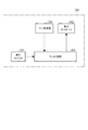
図1は、本実施形態に係るインタラクティブシステムの構成を示すブロック図である。
図1には、インタラクティブシステム1として、発信器としての発光ペン200、プロジェクター100、パーソナルコンピューター(PC)300、およびホワイトボード等の投写面Sとが表されている。
FIG. 1 is a block diagram showing a configuration of an interactive system according to the present embodiment.
In FIG. 1, a
プロジェクター100は、画像投写部10、制御部20、操作受付部21、信号強度設定部22、画像信号入力部31、画像処理部32、撮像検出部50、信号強度制御部としての発光制御部60、同期信号送信部としての赤外線発光部61、同期信号受信部としての赤外線受光部62等を備えて構成されている。
The
画像投写部10は、光源11、光変調装置としての3つの液晶ライトバルブ12R,12G,12B、投写光学系としての投写レンズ13、ライトバルブ駆動部14等を含んでいる。画像投写部10は、光源11から射出された光を、液晶ライトバルブ12R,12G,12Bで変調して画像光を形成し、この画像光を投写レンズ13から投写して投写面S等に表示する。
The
光源11は、超高圧水銀ランプやメタルハライドランプ等からなる放電型の光源ランプ11aと、光源ランプ11aが放射した光を液晶ライトバルブ12R,12G,12B側に反射するリフレクター11bとを含んで構成されている。光源11から射出された光は、図示しないインテグレーター光学系によって輝度分布が略均一な光に変換され、図示しない色分離光学系によって光の3原色である赤色R、緑色G、青色Bの各色光成分に分離された後、それぞれ液晶ライトバルブ12R,12G,12Bに入射する。
The
液晶ライトバルブ12R,12G,12Bは、一対の透明基板間に液晶が封入された液晶パネル等によって構成される。液晶ライトバルブ12R,12G,12Bには、マトリクス状に配列された複数の画素(図示せず)が形成されており、液晶に対して画素毎に駆動電圧を印加可能になっている。ライトバルブ駆動部14が、入力される画像情報に応じた駆動電圧を各画素に印加すると、各画素は、画像情報に応じた光透過率に設定される。このため、光源11から射出された光は、この液晶ライトバルブ12R,12G,12Bを透過することによって変調され、画像情報に応じた画像が色光毎に形成される。形成された各色の画像は、図示しない色合成光学系によって画素毎に合成されてカラー画像となった後、投写レンズ13から投写される。
The liquid
制御部20は、CPU(Central Processing Unit)、各種データの一時記憶等に用いられるRAM、および、マスクROMやフラッシュメモリー、FeRAM(Ferroelectric RAM:強誘電体メモリー)等の不揮発性のメモリー等(いずれも図示せず)を備え、コンピューターとして機能するものである。制御部20は、CPUが不揮発性のメモリーに記憶されている制御プログラムに従って動作することにより、プロジェクター100の動作を統括制御する。また、制御部20は、タイマーを有しており、同期信号の送信や、撮像部51の撮像のタイミング等を計時する。
The
操作受付部21は、ユーザーからの入力操作を受け付けるものであり、ユーザーがプロジェクター100に対して各種指示を行うための複数の操作キーを備えている。操作受付部21が備える操作キーとしては、電源のオン・オフを切り換えるための電源キー、各種設定を行うためのメニュー画像の表示・非表示を切り換えるメニューキー、メニュー画像におけるカーソルの移動等に用いられるカーソルキー、各種設定を決定するための決定キー等がある。ユーザーが操作受付部21の各種操作キーを操作(押下)すると、操作受付部21は、この入力操作を受け付けて、ユーザーの操作内容に応じた操作信号を制御部20に出力する。
The
なお、操作受付部21として、遠隔操作が可能なリモコン(図示せず)を用いた構成としてもよい。この場合、リモコンは、ユーザーの操作内容に応じた赤外線等の操作信号を発信し、リモコン信号受信部がこれを受信して制御部20に伝達する。本実施形態では、赤外線受光部62が、リモコン信号受信部を兼ねている。
The
信号強度設定部22は、不揮発性メモリーからなり、発光制御部60によって制御される赤外線発光部61から発信される赤外線信号(同期信号)の発光強度の強度情報が設定されて、記憶される。本実施形態では、信号強度設定部22には、発光強度の強度情報の設定値として、通常の発光強度で発光する「通常モード」、または、通常よりも弱い発光強度で発光する「弱モード」が設定可能である。
The signal
画像信号入力部31には、PC300とケーブルC1を介した接続を行うための入力端子(図示せず)が備えられており、PC300から画像信号が入力される。画像信号入力部31は、入力される画像信号を、画像処理部32で処理可能な形式の画像情報に変換して、画像処理部32に出力する。
The image
画像処理部32は、画像信号入力部31から入力される画像情報を、液晶ライトバルブ12R,12G,12Bの各画素の階調を表す画像データに変換し、ライトバルブ駆動部14に出力する。ここで、変換された画像データは、R,G,Bの色光別になっており、各液晶ライトバルブ12R,12G,12Bのすべての画素に対応する複数の画素値によって構成されている。画素値とは、対応する画素の光透過率を定めるものであり、この画素値によって、各画素から射出する光の強弱(階調)が規定される。また、画像処理部32は、制御部20の指示に基づき、変換した画像データに対して、明るさ、コントラスト、シャープネス、色合い等を調整するための画質調整処理等を行う。さらに、画像処理部32は、制御部20の指示に基づき、メニュー画像等の画像データを生成する。
The
画像処理部32は、描画メモリー32aを有している。描画メモリー32aは、発光ペン200による描画操作に基づいた描画データを記憶する。
The
画像処理部32は、撮像検出部50から発光ペン200の位置情報を入力する。位置情報は、画像投写部10によって表示された画像(表示画像)内において、発光ペン200が指し示す位置を表す情報である。画像処理部32は、発光ペン200の描画操作がなされた位置に基づいて、描画メモリー32aに描画データを記憶する。そして、画像処理部32は、描画メモリー32aの描画データを、画像信号入力部31から入力された画像データに合成し、ライトバルブ駆動部14に出力する。
The
ライトバルブ駆動部14が、画像処理部32から入力される画像データに従って液晶ライトバルブ12R,12G,12Bを駆動すると、液晶ライトバルブ12R,12G,12Bは、画像データに応じた画像を形成し、この画像が投写レンズ13から投写される。
When the light
撮像検出部50は、撮像部51、画像解析部52、位置情報検出部53を含んで構成されている。撮像検出部50は、制御部20によって制御される。撮像検出部50は、投写面Sを撮像し、画像解析して、発光ペン200の位置を検出する。
The
撮像部51は、CCD(Charge Coupled Device)センサー、或いはCMOS(Complementary Metal Oxide Semiconductor)センサー等からなる撮像素子等(図示せず)と、撮像対象から発せられた光を撮像素子上に結像させるための撮像レンズ(図示せず)を備えている。撮像部51は、プロジェクター100の投写レンズ13の近傍に配置され、投写面Sに投写された画像(以降、「投写画像」とも呼ぶ。)を含む範囲を制御部20の指示に基づいて撮像する。そして、撮像部51は、撮像した画像(以降、「撮像画像」とも呼ぶ。)を表す画像情報を順次生成し、画像解析部52に出力する。
The
画像解析部52は、画像解析用の処理装置やメモリー等(いずれも図示せず)を有して構成されている。画像解析部52は、撮像部51から入力された撮像画像の画像情報の解析を行う。画像解析部52は、解析結果を位置情報検出部53に出力する。なお、画像解析部52は、撮像画像上の位置情報から画像信号に基づく画像上の位置情報への変換を行う。
The
位置情報検出部53は、画像解析部52の解析結果に基づいて、発光ペン200の位置情報を検出する。位置情報検出部53は、発光ペン200の位置情報を画像処理部32に出力する。
The position information detection unit 53 detects the position information of the light-emitting
制御部20の不揮発性のメモリーには、発光ペン200を描画デバイス(発信器)として利用するためのソフトウェア(デバイスドライバー)が記憶されている。そして、このソフトウェアが起動した状態では、画像処理部32は、撮像検出部50から入力される位置情報に基づいて、投写画像内で発光ペン200の描画操作がなされた位置をそれぞれ認識する。そして、画像処理部32は、描画メモリー32aに描画データを記憶させ、描画データに基づいた画像データをライトバルブ駆動部14に出力する。
The nonvolatile memory of the
発光制御部60は、制御部20の指示に基づいて赤外線発光部61の発光を制御する。具体的には、発光制御部60は、赤外線発光部61が有する赤外発光ダイオードに電力を供給することにより赤外発光ダイオードを点灯させるとともに、電力の供給を停止して赤外発光ダイオードを消灯させることができる。
The light emission control unit 60 controls light emission of the infrared
また、発光制御部60は、赤外線発光部61が発光する赤外線信号の発光強度を制御することができる。本実施形態では、赤外線発光部61は、複数の赤外発光ダイオードを有しており、発光制御部60は、発光させる赤外発光ダイオードの数を切り換えることで、発光強度を制御する。具体的には、全ての赤外発光ダイオードを点灯/消灯させる通常モードと、一部の赤外発光ダイオードを点灯/消灯させる弱モードとに切り換えることが可能である。
Further, the light emission control unit 60 can control the emission intensity of the infrared signal emitted from the infrared
赤外線発光部61は、赤外発光ダイオードを有する赤外線発光装置(図示せず)等で構成され、発光制御部60から入力される制御情報に基づき、赤外発光ダイオードを発光させて、赤外線信号を外部に発信する。具体的には、赤外光の同期信号を発信する。
The infrared
赤外線受光部62は、赤外線受信モジュール等を有して構成され、他のプロジェクター等から発せられた赤外線信号を受信し、制御部20に通知する。また、本実施形態では、赤外線受光部62は、リモコン信号受信部と兼用されている。
The infrared
次に、発光ペン200について説明する。発光ペン200は、ペン状の本体の先端部(ペン先)に、押圧スイッチと、同期信号を受信する受信部としてのペン受信部と、光信号としての赤外光を発する発光ダイオードとを備えている。
図2は、本実施形態に係る発光ペン200の構成を示すブロック図である。
Next, the light-emitting
FIG. 2 is a block diagram illustrating a configuration of the light-emitting
発光ペン200は、ペン制御部220、押圧スイッチ221、同期信号である赤外線信号を受光するペン受信部230、赤外光を発する発光ダイオード240等を備えて構成されている。そして、ユーザーによって、発光ペン200のペン先を投写面Sに押し付ける操作(押圧操作)が行われて、押圧スイッチ221が押圧されると、ペン制御部220は、ペン受信部230によって受信される同期信号に同期するように、発光ダイオード240を発光させる。このペン制御部220および発光ダイオード240が、光信号発信部に相当する。
The
ここで、プロジェクター100の赤外線発光部61から発せられる同期信号のタイミングと、発光ペン200が発光するタイミングと、プロジェクター100が発光ペン200の発光を撮像するタイミングとについて説明する。
図3は、インタラクティブシステム1における同期タイミングを表すタイミングチャートである。
Here, the timing of the synchronization signal emitted from the infrared
FIG. 3 is a timing chart showing the synchronization timing in the
図3に示すように、プロジェクター100の赤外線発光部61が発信する同期信号は、t1時間間隔で出力される。これは、タイマーを有する制御部20が発光制御部60に指示を出して、赤外線発光部61に発信させる。発光ペン200は、受信部が同期信号を受信する。そして、発光ペン200は、同期信号を受信してからt2時間後に、発光ダイオードを発光させる。プロジェクター100の撮像部51は、制御部20からの指示により、赤外線発光部61が同期信号を発信してからt3時間後に、発光ペン200の発光を撮像する。ここで、t3時間はt2時間より大きいものとする。
As shown in FIG. 3, the synchronization signal transmitted from the infrared
このようなタイミングで、プロジェクター100の赤外線発光部61が同期信号を発信し、発光ペン200が発光し、プロジェクター100の撮像部51が撮像することで、プロジェクター100は、発光ペン200の発光を正しく撮像することができる。
At such timing, the infrared
ここで、インタラクティブシステムが複数設置された態様について説明する。
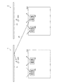
図4は、インタラクティブシステムが並設された場合の説明図である。
Here, a mode in which a plurality of interactive systems are installed will be described.
FIG. 4 is an explanatory diagram when interactive systems are arranged in parallel.
図4に示すように、インタラクティブシステム1は、発光ペン200とプロジェクター100とを有して構成されており、投写面Sに対向して設置されている。プロジェクター100は、赤外線発光部61と赤外線受光部62とを有している。また、インタラクティブシステム2は、発光ペン600と、プロジェクター500とを有して構成されており、投写面S1に対向して設置されている。プロジェクター500は、赤外線発光部561と赤外線受光部562とを有している。そして、インタラクティブシステム1およびインタラクティブシステム2は、並設されている。
As shown in FIG. 4, the
このようにインタラクティブシステムが並設されると、一方のインタラクティブシステムのプロジェクターから発せられた赤外線信号を、他方のインタラクティブシステムの発光ペンが受信してしまう場合がある。図4では、プロジェクター500の赤外線発光部561が発した赤外線信号IRを、インタラクティブシステム1の発光ペン200が受信してしまう態様を表している。発光ペン200は、投写面Sの近くで使用されるため、投写面Sによって反射された赤外線信号IRを受信してしまう場合も多い。
When interactive systems are arranged side by side in this way, the light emitting pen of the other interactive system may receive the infrared signal emitted from the projector of one interactive system. FIG. 4 shows an aspect in which the
発光ペン200が、プロジェクター500から発せられた赤外線信号(第2の同期信号)を受信してしまうと、発光ペン200の発光タイミングがずれてしまい、プロジェクター100の撮像部51が、発光ペン200の発光を正常に撮像することができなくなる。よって、インタラクティブ機能が正常に動作しなくなる。本実施形態では、赤外線発光部61から発信する赤外線信号の発光強度を変化させたり、他のプロジェクター500から発せられる同期信号(第2の同期信号)に、赤外線信号の発光タイミングを同調させたりすることによって、インタラクティブ機能の動作を安定させる。以下に詳細を述べる。
When the
ここで、赤外線発光部61の発光強度の設定について説明する。本実施形態のプロジェクター100では、ユーザーがメニュー画像によって、赤外線信号(同期信号)の発光強度の設定を行うことができる。そして、プロジェクター100は、周囲に他のプロジェクターが存在すると判断した場合に、発光強度の設定値に基づいて、発光強度を切り換える。
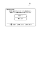
図5は、発光強度を設定させるメニュー画像の説明図である。
Here, the setting of the light emission intensity of the infrared
FIG. 5 is an explanatory diagram of a menu image for setting the emission intensity.
操作受付部21に備わるメニューキーが押下され、発光強度設定メニューが選択されると、制御部20は、画像処理部32に指示を出して、図5に示す発光強度設定メニュー画像M1を表示させる。
When the menu key provided in the
発光強度設定メニュー画像M1の上部には、「発光強度設定」の文字列が表示される。その下には、「周囲に他のプロジェクターが存在する場合、発光ペンに送信する信号を弱くしますか?」という文字列が表示される。発光強度設定メニュー画像M1の中央部には、設定候補として、「弱くする」、「弱くしない」が表示されている。ここで、「弱くする」は、発光強度の設定を弱モードにすることを示し、「弱くしない」は、発光強度の設定を通常モードにすることを示す。ユーザーが、発光強度設定メニュー画像M1において表示されている設定候補の中から、所望の設定を選択し決定することにより、制御部20は、その設定値の情報(モード)を信号強度設定部22に記憶する。このときの操作が、所定の操作に相当する。
On the upper part of the light emission intensity setting menu image M1, a character string of “light emission intensity setting” is displayed. Below that, a character string “Would you like to weaken the signal sent to the light-emitting pen when there are other projectors in the vicinity?” Is displayed. In the central portion of the light emission intensity setting menu image M1, “weak” and “not weak” are displayed as setting candidates. Here, “decrease” indicates that the emission intensity is set to the weak mode, and “do not decrease” indicates that the emission intensity is set to the normal mode. When the user selects and determines a desired setting from the setting candidates displayed in the light emission intensity setting menu image M1, the
次に、プロジェクター100の起動時に実行される赤外線信号の発光強度の切換処理(以降、「赤外光発光強度切換処理」と呼ぶ。)について説明する。なお、この赤外光発光強度切換処理は、起動後も定期的なタイミングで実行されるものとする。
図6は、プロジェクター100の赤外光発光強度切換処理のフローチャートである。
Next, an infrared signal emission intensity switching process (hereinafter referred to as “infrared light emission intensity switching process”) executed when the
FIG. 6 is a flowchart of the infrared light emission intensity switching process of the
プロジェクター100が起動されると、制御部20は、周囲に他のプロジェクターが存在するか否かを判断する(ステップS101)。具体的には、制御部20が発光制御部60に指示を出して、同期信号を含む赤外線信号の発信を停止させる。そして、制御部20は、赤外線受光部62が、赤外線信号を受信しているか否かを判断する。赤外線信号を受信していれば、他のプロジェクターから発信されている赤外線信号であると判断して、他のプロジェクターが周囲に存在すると判断する。
When the
周囲に他のプロジェクターが存在している場合(ステップS101:YES)、制御部20は、他のプロジェクターとの同期をとる(ステップS102)。具体的には、赤外線受光部62が受信している赤外光の同期信号(第2の同期信号)と同期するように、制御部20が発光制御部60に指示を出し、赤外線発光部61に赤外光の同期信号を発信させる。つまり、他のプロジェクターの同期信号(第2の同期信号)に、赤外光の発光タイミングを同調させる。
When other projectors exist around (step S101: YES), the
そして、制御部20は、発光強度の設定が「弱モード」になっているか否かを判断する(ステップS103)。具体的には、制御部20が、信号強度設定部22に記憶されている発光強度の設定値を参照して判断する。
Then, the
発光強度の設定が「弱モード」になっている場合(ステップS103:YES)、制御部20は、発光制御部60に指示を出して、赤外線発光部61が発光する赤外光(同期信号)の発光強度を弱くする(ステップS104)。そして、赤外光発光強度切換処理を終了する。
When the setting of the light emission intensity is “weak mode” (step S103: YES), the
発光強度の設定が「弱モード」になっていない場合(ステップS103:NO)、即ち「通常モード」になっている場合、制御部20は、発光制御部60に指示を出して、赤外線発光部61が発光する赤外光(同期信号)の発光強度を通常にする(ステップS105)。そして、赤外光発光強度切換処理を終了する。
When the setting of the light emission intensity is not “weak mode” (step S103: NO), that is, when it is “normal mode”, the
周囲に他のプロジェクターが存在していない場合(ステップS101:NO)、ステップS105に移行して、赤外光の発光強度を通常にする。そして、赤外光発光強度切換処理を終了する。 When there is no other projector in the surroundings (step S101: NO), the process proceeds to step S105, and the emission intensity of infrared light is set to normal. Then, the infrared light emission intensity switching process ends.
上述した実施形態によれば、以下の効果が得られる。
(1)インタラクティブシステム1のプロジェクター100の発光制御部60は、赤外線発光部61が発信する同期信号である赤外線信号の発光強度を制御する。これにより、同期信号の強度を弱くすると、他のインタラクティブシステム2に対する同期信号の干渉を低減することが可能になり、自他のそれぞれのインタラクティブシステムにおいて、プロジェクターがそれぞれの発光ペンと同期することができる。つまり、使用環境による影響が低減され、それぞれのプロジェクターが、それぞれの発光ペンを用いたインタラクティブ機能を安定して行うことができるため、有益である。
According to the embodiment described above, the following effects can be obtained.
(1) The light emission control unit 60 of the
(2)インタラクティブシステム1のプロジェクター100は、同期信号である赤外線信号の発光強度を設定する発光強度設定メニュー画像M1を表示することができる。そして、ユーザーは、赤外線信号の発光強度を選択して設定することができる。そして、周囲に他のプロジェクター500が存在する場合に、プロジェクター100の赤外線発光部61は、発光強度の設定に従って、赤外線信号を発光する。これにより、ユーザーが、赤外線信号の発光強度を設定することが可能になるため、利便性が向上する。
(2) The
(3)インタラクティブシステム1のプロジェクター100は、周囲に他のプロジェクター500が存在する場合、即ち、赤外線受光部62が、他のプロジェクター500から発信された同期信号(第2の同期信号)を受信した場合には、受信した同期信号(第2の同期信号)に同期した同期信号を、赤外線発光部61から発信する。つまり、プロジェクター100とプロジェクター500とは、発信する同期信号のタイミングを同期(同調)させる。これにより、発光ペン200および発光ペン600は、プロジェクター100およびプロジェクター500と同期することができるため、それぞれのプロジェクターがそれぞれの発光ペンの発光を撮像することが可能になる。つまり、それぞれのプロジェクターが、発光ペンによるインタラクティブ機能を安定して行うことが可能になるため、有益である。
(3) The
(4)インタラクティブシステム1のプロジェクター100は、赤外光発光強度切換処理を、起動時および起動後の定期的なタイミングで実行する。これにより、他のプロジェクター500が存在するか否かを起動時および定期的に判断でき、他のプロジェクターの存在が検出されたときに、直ちに赤外光(赤外線信号)の発光強度を変更することが可能になるため、有益である。
(4) The
(5)インタラクティブシステム1のプロジェクター100が発する同期信号は、赤外線信号である。これにより、プロジェクター100および発光ペン200の構成を、簡易にすることができる。
(5) The synchronization signal generated by the
(6)インタラクティブシステム1のプロジェクター100の発光制御部60は、赤外線発光部61が有する複数の赤外発光ダイオードの発光数を変更することで、赤外線信号の発光強度を変化させる。これにより、赤外線信号の発光強度を通常モードおよび弱モードに切り換えることが可能になる。
(6) The light emission control unit 60 of the
なお、上述した実施形態に限定されず、種々の変更や改良等を加えて実施することが可能である。変形例を以下に述べる。 In addition, it is not limited to embodiment mentioned above, It is possible to implement by adding various change, improvement, etc. A modification will be described below.
(変形例1)上記実施形態では、プロジェクター100の赤外線発光部61は、周囲に他のプロジェクター500が存在する場合に、ユーザーによって設定された発光強度の設定値に従って、赤外線信号を発光するものとした。しかし、赤外線発光部61は、周囲のプロジェクター500の存在に関わらず、ユーザーによって設定された発光強度の設定値に従って、赤外線信号を発光してもよい。
(Modification 1) In the above embodiment, the infrared
(変形例2)上記実施形態では、プロジェクター100の赤外線発光部61は、周囲に他のプロジェクター500が存在する場合に、ユーザーによって設定された発光強度に従って、赤外線信号を発光するものとしたが、発光強度は、ユーザーによって設定されるものに限定されない。例えば、赤外線受光部62によって受光された他のプロジェクター500の赤外線信号の受光強度に応じて、発光強度を切り換えてもよい。具体的には、受光強度が所定の強度以上の場合には、他のプロジェクター500が近くに存在するものと判断して、赤外線発光部61が発光する発光強度を弱く(弱モード)し、受光強度が所定の強度より小さい場合には、他のプロジェクター500が遠くに存在するものと判断して、発光強度を強く(通常モード)してもよい。
(Modification 2) In the above embodiment, the infrared
(変形例3)上記実施形態では、赤外光発光強度切換処理において、他のプロジェクター500との同期をとった後、制御部20が、発光強度の設定値を信号強度設定部22から読み出し、その設定値に応じて、発光制御部60に、赤外線信号の発光強度を切り換えさせるものとした。しかし、これに限定するものではなく、プロジェクター100は、他のプロジェクター500との同期をとった際に、発光強度設定メニュー画像M1と同様なメニュー画像を投写画像に表示させてもよい。そして、当該メニュー画像でユーザーに発光強度を選択設定させ、設定された発光強度に応じて、制御部20は、発光制御部60に、赤外線信号の発光強度を切り換えさせてもよい。
(Modification 3) In the above embodiment, after synchronizing with the
(変形例4)上記実施形態では、発光制御部60が制御し、赤外線発光部61が発光する赤外線信号の発光強度は、「通常モード」と「弱モード」とに切り換え可能としたが、発光強度の切り換えは、この2段階に限定するものではない。例えば、発光強度を3段階以上に切り換え可能としてもよい。
(Modification 4) In the above embodiment, the light emission intensity of the infrared signal controlled by the light emission control unit 60 and emitted from the infrared
(変形例5)上記実施形態では、赤外線信号の発光強度の設定は、発光強度設定メニュー画像M1を表示させて行うものとしたが、これに限定するものではない。例えば、操作受付部21に、発光強度を切り換えるためのキーを備えるものとし、当該キーを押下することで、発光強度の設定値を変更して、信号強度設定部22に設定記憶させるものとしてもよい。
(Modification 5) In the above embodiment, the emission intensity of the infrared signal is set by displaying the emission intensity setting menu image M1, but the present invention is not limited to this. For example, the
(変形例6)上記実施形態では、同期信号は、赤外線信号(赤外光)としたが、これに限定するものではない。例えば、同期信号は、可視光としてもよいし、無線通信用電波等としてもよい。 (Modification 6) In the above embodiment, the synchronization signal is an infrared signal (infrared light), but the present invention is not limited to this. For example, the synchronization signal may be visible light or radio communication radio waves.
(変形例7)上記実施形態では、発信器は、赤外光を発する発光ペン200としたが、このような発光ペンに限定するものではない。例えば、可視光を発する発信器としてもよいし、無線通信用電波等を利用するようにしてもよい。
(Modification 7) In the above embodiment, the transmitter is the light-emitting
(変形例8)上記実施形態では、プロジェクター100に画像信号を供給するのはPC300としているが、パーソナルコンピューターに限定するものではない。他の画像供給装置としてもよい。
(Modification 8) In the above embodiment, the image signal is supplied to the
(変形例9)上記実施形態では、プロジェクター100とPC300とは、ケーブルC1で接続されるものとしたが、無線通信によって情報の入出力を行ってもよい。
(Modification 9) In the above embodiment, the
(変形例10)上記実施形態では、光源11は、放電型の光源ランプ11aを有して構成されているが、LED(Light Emitting Diode)光源やレーザー等の固体光源や、その他の光源を用いることもできる。
(Modification 10) In the above embodiment, the
(変形例11)上記実施形態では、プロジェクター100は、光変調装置として、透過型の液晶ライトバルブ12R,12G,12Bを用いているが、反射型の液晶ライトバルブ等、反射型の光変調装置を用いることも可能である。また、入射した光の射出方向を、画素としてのマイクロミラー毎に制御することにより、光源から射出した光を変調する微小ミラーアレイデバイス等を用いることもできる。
(Modification 11) In the above-described embodiment, the
1,2…インタラクティブシステム、10…画像投写部、11…光源、11a…光源ランプ、11b…リフレクター、12R,12G,12B…液晶ライトバルブ、13…投写レンズ、14…ライトバルブ駆動部、20…制御部、21…操作受付部、22…信号強度設定部、31…画像信号入力部、32…画像処理部、32a…描画メモリー、50…撮像検出部、51…撮像部、52…画像解析部、53…位置情報検出部、60…発光制御部、61…赤外線発光部、62…赤外線受光部、100,500…プロジェクター、200,600…発光ペン、220…ペン制御部、221…押圧スイッチ、230…ペン受信部、240…発光ダイオード、300…PC、561…赤外線発光部、562…赤外線受光部、S,S1…投写面、C1…ケーブル。
DESCRIPTION OF
Claims (6)
前記プロジェクターは、
同期信号の強度情報が設定される信号強度設定部と、
前記信号強度設定部の設定に基づいて前記同期信号の強度を制御する信号強度制御部と、
前記同期信号を送信する同期信号送信部と、
前記発信器から発信される前記光信号を撮像する撮像部と、
を有し、
前記発信器は、
前記同期信号を受信する受信部と、
前記受信部が受信した前記同期信号に同期して前記光信号を発信する光信号発信部と、
を有し、
前記プロジェクターは、
前記同期信号を受信する同期信号受信部をさらに有し、
前記同期信号受信部が、他のプロジェクターから第2の同期信号を受信した場合に、前記同期信号送信部は、前記同期信号を前記第2の同期信号と同期させて送信することを特徴とするインタラクティブシステム。 An interactive system including a transmitter for transmitting an optical signal and a projector,
The projector is
A signal strength setting unit in which the strength information of the synchronization signal is set;
A signal strength control unit for controlling the strength of the synchronization signal based on the setting of the signal strength setting unit;
A synchronization signal transmitter for transmitting the synchronization signal;
An imaging unit that images the optical signal transmitted from the transmitter;
Have
The transmitter is
A receiver for receiving the synchronization signal;
An optical signal transmitter that transmits the optical signal in synchronization with the synchronization signal received by the receiver;
I have a,
The projector is
A synchronization signal receiver for receiving the synchronization signal;
When the synchronization signal receiving unit receives a second synchronization signal from another projector, the synchronization signal transmitting unit transmits the synchronization signal in synchronization with the second synchronization signal. Interactive system.
前記同期信号送信部は赤外発光ダイオードを有して構成され、前記同期信号送信部が送信する前記同期信号は、赤外線信号であることを特徴とするインタラクティブシステム。 The interactive system according to claim 1 ,
The interactive system, wherein the synchronization signal transmission unit includes an infrared light emitting diode, and the synchronization signal transmitted by the synchronization signal transmission unit is an infrared signal.
前記同期信号送信部は、前記赤外発光ダイオードを複数有しており、前記信号強度制御部は、複数の前記赤外発光ダイオードの発光数を変更することで、前記同期信号の強度を制御することを特徴とするインタラクティブシステム。 An interactive system according to claim 2 ,
The synchronization signal transmission unit has a plurality of infrared light emitting diodes, and the signal intensity control unit controls the intensity of the synchronization signal by changing the number of light emission of the plurality of infrared light emitting diodes. An interactive system characterized by that.
前記プロジェクターは、
所定の操作を受け付ける操作受付部と、
前記操作受付部が前記所定の操作を受け付けると、前記所定の操作に基づいた前記同期信号の強度情報を、前記信号強度設定部に設定する制御部と、
をさらに有することを特徴とするインタラクティブシステム。 An interactive system according to any one of claims 1 to 3 ,
The projector is
An operation reception unit for receiving a predetermined operation;
When the operation accepting unit accepts the predetermined operation, a control unit that sets strength information of the synchronization signal based on the predetermined operation in the signal strength setting unit;
An interactive system characterized by further comprising:
前記プロジェクターは、
前記信号強度設定部の設定に基づいて前記同期信号の強度を制御する信号強度制御ステップと、
前記同期信号を送信する同期信号送信ステップと、
前記発信器から発信される前記光信号を撮像する撮像ステップと、
を有し、
前記発信器は、
前記同期信号を受信する受信ステップと、
前記受信ステップによって受信された前記同期信号に同期して前記光信号を発信する光信号発信ステップと、
を有し、
前記プロジェクターは、
前記同期信号を受信する同期信号受信ステップをさらに有し、
前記同期信号受信ステップにおいて、他のプロジェクターから第2の同期信号を受信した場合に、前記同期信号送信ステップにおいて、前記同期信号を前記第2の同期信号と同期させて送信することを特徴とするインタラクティブシステムの制御方法。 An interactive system control method comprising: a transmitter that transmits an optical signal; and a projector having a signal intensity setting unit in which intensity information of a synchronization signal is set.
The projector is
A signal strength control step for controlling the strength of the synchronization signal based on the setting of the signal strength setting unit;
A synchronization signal transmission step of transmitting the synchronization signal;
An imaging step of imaging the optical signal transmitted from the transmitter;
Have
The transmitter is
Receiving step for receiving the synchronization signal;
An optical signal transmission step of transmitting the optical signal in synchronization with the synchronization signal received by the reception step;
I have a,
The projector is
A synchronization signal receiving step of receiving the synchronization signal;
In the synchronization signal receiving step, when the second synchronization signal is received from another projector, the synchronization signal is transmitted in synchronization with the second synchronization signal in the synchronization signal transmission step. Control method of interactive system.
前記信号強度設定部の設定に基づいて前記同期信号の強度を制御する信号強度制御部と、
前記同期信号を送信する同期信号送信部と、
を有し、
前記同期信号を受信する同期信号受信部をさらに有し、
前記同期信号受信部が、他のプロジェクターから第2の同期信号を受信した場合に、前記同期信号送信部は、前記同期信号を前記第2の同期信号と同期させて送信することを特徴とするプロジェクター。 A signal strength setting unit in which the strength information of the synchronization signal is set;
A signal strength control unit for controlling the strength of the synchronization signal based on the setting of the signal strength setting unit;
A synchronization signal transmitter for transmitting the synchronization signal;
Have
A synchronization signal receiver for receiving the synchronization signal;
When the synchronization signal receiving unit receives a second synchronization signal from another projector, the synchronization signal transmitting unit transmits the synchronization signal in synchronization with the second synchronization signal. projector.
Priority Applications (10)
| Application Number | Priority Date | Filing Date | Title |
|---|---|---|---|
| JP2012204045A JP6060581B2 (en) | 2012-09-18 | 2012-09-18 | Interactive system, interactive system control method, and projector |
| IN2302DEN2015 IN2015DN02302A (en) | 2012-09-18 | 2013-09-13 | |
| PCT/JP2013/005456 WO2014045560A1 (en) | 2012-09-18 | 2013-09-13 | Interactive system, control method for interactive system, and projector |
| RU2015114435A RU2617932C2 (en) | 2012-09-18 | 2013-09-13 | Interactive system, method for controlling interactive system and projector |
| CN201310418284.1A CN103677444B (en) | 2012-09-18 | 2013-09-13 | Interactive system, the control method of interactive system and projecting apparatus |
| BR112015006065A BR112015006065A2 (en) | 2012-09-18 | 2013-09-13 | interactive system, control method for interactive system and projector |
| US14/423,615 US9632616B2 (en) | 2012-09-18 | 2013-09-13 | Interactive system, control method for interactive system, and projector |
| EP13776865.1A EP2898398B1 (en) | 2012-09-18 | 2013-09-13 | Interactive system, control method for interactive system, and projector |
| KR1020157009866A KR101788029B1 (en) | 2012-09-18 | 2013-09-13 | Interactive system, control method for interactive system, and projector |
| TW102133396A TWI595302B (en) | 2012-09-18 | 2013-09-14 | Interactive system, control method for interactive system, and projector |
Applications Claiming Priority (1)
| Application Number | Priority Date | Filing Date | Title |
|---|---|---|---|
| JP2012204045A JP6060581B2 (en) | 2012-09-18 | 2012-09-18 | Interactive system, interactive system control method, and projector |
Publications (2)
| Publication Number | Publication Date |
|---|---|
| JP2014059695A JP2014059695A (en) | 2014-04-03 |
| JP6060581B2 true JP6060581B2 (en) | 2017-01-18 |
Family
ID=49356480
Family Applications (1)
| Application Number | Title | Priority Date | Filing Date |
|---|---|---|---|
| JP2012204045A Expired - Fee Related JP6060581B2 (en) | 2012-09-18 | 2012-09-18 | Interactive system, interactive system control method, and projector |
Country Status (10)
| Country | Link |
|---|---|
| US (1) | US9632616B2 (en) |
| EP (1) | EP2898398B1 (en) |
| JP (1) | JP6060581B2 (en) |
| KR (1) | KR101788029B1 (en) |
| CN (1) | CN103677444B (en) |
| BR (1) | BR112015006065A2 (en) |
| IN (1) | IN2015DN02302A (en) |
| RU (1) | RU2617932C2 (en) |
| TW (1) | TWI595302B (en) |
| WO (1) | WO2014045560A1 (en) |
Cited By (1)
| Publication number | Priority date | Publication date | Assignee | Title |
|---|---|---|---|---|
| JP2014183385A (en) * | 2013-03-18 | 2014-09-29 | Seiko Epson Corp | Projector and control method |
Families Citing this family (12)
| Publication number | Priority date | Publication date | Assignee | Title |
|---|---|---|---|---|
| CN105320360A (en) * | 2014-07-29 | 2016-02-10 | 中强光电股份有限公司 | Touch device and touch sensing method thereof |
| CN104501001B (en) * | 2014-11-28 | 2016-11-23 | 广景科技有限公司 | A kind of intelligence projection bulb and interactive and intelligence projecting method thereof |
| JP6503828B2 (en) * | 2015-03-27 | 2019-04-24 | セイコーエプソン株式会社 | Interactive projection system, pointer, and control method of interactive projection system |
| JP6636386B2 (en) * | 2016-05-18 | 2020-01-29 | シャープ株式会社 | Touch scan control device, touch scan control method, and touch scan control program |
| CN106506076A (en) * | 2016-10-14 | 2017-03-15 | 乐视控股(北京)有限公司 | A kind of method of virtual reality system and its information transfer, device |
| JP7010076B2 (en) * | 2018-03-13 | 2022-01-26 | セイコーエプソン株式会社 | Image projection system, projector and image projection system control method |
| JP7119488B2 (en) * | 2018-03-27 | 2022-08-17 | セイコーエプソン株式会社 | Projector and projector control method |
| KR102169626B1 (en) * | 2018-11-21 | 2020-10-23 | (주)이즈커뮤니케이션즈 | Input system for a computer having function of identifying a input device |
| JP2021033554A (en) | 2019-08-22 | 2021-03-01 | セイコーエプソン株式会社 | Projection system, position detection system, and position detection method |
| US11652969B2 (en) | 2020-02-10 | 2023-05-16 | Ricoh Company, Ltd. | Projection apparatus and operation detection apparatus |
| JP2021128657A (en) * | 2020-02-17 | 2021-09-02 | セイコーエプソン株式会社 | Position detection method, position detection device, and position detection system |
| JP2021193499A (en) * | 2020-06-08 | 2021-12-23 | セイコーエプソン株式会社 | Position detection system, position detection apparatus, projector, and position detection method |
Family Cites Families (21)
| Publication number | Priority date | Publication date | Assignee | Title |
|---|---|---|---|---|
| JP2622620B2 (en) * | 1989-11-07 | 1997-06-18 | プロクシマ コーポレイション | Computer input system for altering a computer generated display visible image |
| US5926168A (en) * | 1994-09-30 | 1999-07-20 | Fan; Nong-Qiang | Remote pointers for interactive televisions |
| US6104512A (en) * | 1998-01-23 | 2000-08-15 | Motorola, Inc. | Method for adjusting the power level of an infrared signal |
| US6847356B1 (en) * | 1999-08-13 | 2005-01-25 | Canon Kabushiki Kaisha | Coordinate input device and its control method, and computer readable memory |
| JP4018326B2 (en) * | 2000-08-07 | 2007-12-05 | キヤノン株式会社 | Coordinate input device, control method therefor, and computer-readable memory |
| WO2004079558A1 (en) * | 2003-03-03 | 2004-09-16 | Matsushita Electric Industrial Co., Ltd. | Projector system |
| TWI291122B (en) * | 2004-06-11 | 2007-12-11 | Micro Nits Co Ltd | Array type optical sensor pointing system and its method |
| US7410260B2 (en) * | 2005-08-04 | 2008-08-12 | Texas Instruments Incorporated | Use of a CCD camera in a projector platform for smart screen capability and other enhancements |
| JP4728740B2 (en) * | 2005-08-23 | 2011-07-20 | Necディスプレイソリューションズ株式会社 | Electronic pen, electronic blackboard system, and projector system |
| JP4811203B2 (en) * | 2006-09-06 | 2011-11-09 | 沖電気工業株式会社 | Projector, terminal, and image communication system |
| US8319699B2 (en) * | 2007-08-09 | 2012-11-27 | Barco N.V. | Multiple display channel system with high dynamic range |
| JP2009043139A (en) * | 2007-08-10 | 2009-02-26 | Mitsubishi Electric Corp | Position detecting device |
| JP5094566B2 (en) * | 2008-06-02 | 2012-12-12 | 三菱電機株式会社 | Video display system |
| US20100321382A1 (en) * | 2009-06-18 | 2010-12-23 | Scalable Display Technologies, Inc. | System and method for injection of mapping functions |
| JP2011028629A (en) | 2009-07-28 | 2011-02-10 | Sanyo Electric Co Ltd | Presentation system |
| JP5493702B2 (en) * | 2009-10-26 | 2014-05-14 | セイコーエプソン株式会社 | Projection display with position detection function |
| JP5683097B2 (en) | 2009-12-15 | 2015-03-11 | キヤノン株式会社 | Projection system |
| JP2011204059A (en) | 2010-03-26 | 2011-10-13 | Seiko Epson Corp | Information input system and information input apparatus |
| CN102135842B (en) * | 2011-04-06 | 2013-02-27 | 南京方瑞科技有限公司 | Synchronous light pen electronic whiteboard system |
| US9292109B2 (en) * | 2011-09-22 | 2016-03-22 | Smart Technologies Ulc | Interactive input system and pen tool therefor |
| US9652029B2 (en) * | 2012-01-09 | 2017-05-16 | Epson Norway Research And Development As | Low interference system and method for synchronization, identification and tracking of visual and interactive systems |
-
2012
- 2012-09-18 JP JP2012204045A patent/JP6060581B2/en not_active Expired - Fee Related
-
2013
- 2013-09-13 CN CN201310418284.1A patent/CN103677444B/en active Active
- 2013-09-13 BR BR112015006065A patent/BR112015006065A2/en not_active IP Right Cessation
- 2013-09-13 WO PCT/JP2013/005456 patent/WO2014045560A1/en active Application Filing
- 2013-09-13 KR KR1020157009866A patent/KR101788029B1/en active IP Right Grant
- 2013-09-13 EP EP13776865.1A patent/EP2898398B1/en active Active
- 2013-09-13 US US14/423,615 patent/US9632616B2/en active Active
- 2013-09-13 RU RU2015114435A patent/RU2617932C2/en active
- 2013-09-13 IN IN2302DEN2015 patent/IN2015DN02302A/en unknown
- 2013-09-14 TW TW102133396A patent/TWI595302B/en active
Cited By (1)
| Publication number | Priority date | Publication date | Assignee | Title |
|---|---|---|---|---|
| JP2014183385A (en) * | 2013-03-18 | 2014-09-29 | Seiko Epson Corp | Projector and control method |
Also Published As
| Publication number | Publication date |
|---|---|
| RU2617932C2 (en) | 2017-04-28 |
| IN2015DN02302A (en) | 2015-08-28 |
| BR112015006065A2 (en) | 2017-07-04 |
| RU2015114435A (en) | 2016-11-10 |
| CN103677444B (en) | 2018-03-20 |
| EP2898398B1 (en) | 2017-08-02 |
| WO2014045560A1 (en) | 2014-03-27 |
| KR20150056841A (en) | 2015-05-27 |
| JP2014059695A (en) | 2014-04-03 |
| KR101788029B1 (en) | 2017-10-19 |
| US9632616B2 (en) | 2017-04-25 |
| TWI595302B (en) | 2017-08-11 |
| CN103677444A (en) | 2014-03-26 |
| TW201413365A (en) | 2014-04-01 |
| EP2898398A1 (en) | 2015-07-29 |
| US20150324054A1 (en) | 2015-11-12 |
Similar Documents
| Publication | Publication Date | Title |
|---|---|---|
| JP6060581B2 (en) | Interactive system, interactive system control method, and projector | |
| JP5673191B2 (en) | Interactive system, position information conversion method, and projector | |
| US9396520B2 (en) | Projector system and control method thereof | |
| US9992466B2 (en) | Projector with calibration using a plurality of images | |
| JP6326895B2 (en) | POSITION DETECTION DEVICE, POSITION DETECTION SYSTEM, AND POSITION DETECTION DEVICE CONTROL METHOD | |
| JP2014191380A (en) | Electronic pen, interactive system, and method of controlling electronic pen | |
| JP6119170B2 (en) | Projector and projector control method | |
| JP5672126B2 (en) | Interactive system, interactive system control method, and projector | |
| JP6273671B2 (en) | Projector, display system, and projector control method | |
| US10909947B2 (en) | Display device, display system, and method of controlling display device | |
| CN108629726B (en) | Information processing device, image display method, display system, and recording medium | |
| JP6015354B2 (en) | Image display system and method for controlling image display system | |
| JP6295758B2 (en) | Display device and display device control method | |
| JP5899993B2 (en) | Image display device, image display system, and control method of image display device | |
| JP2015146611A (en) | Interactive system and control method of interactive system | |
| JP6145963B2 (en) | Projector, display system, and projector control method | |
| JP5724607B2 (en) | Interactive system and method for controlling interactive system | |
| US10078378B2 (en) | Position detection device, display device, method of controlling position detection device, and method controlling display device for discriminating a pointing element | |
| JP5967183B2 (en) | Interactive system, projector, and projector control method | |
| JP2022150346A (en) | Display method and display system |
Legal Events
| Date | Code | Title | Description |
|---|---|---|---|
| RD04 | Notification of resignation of power of attorney |
Free format text: JAPANESE INTERMEDIATE CODE: A7424 Effective date: 20150108 |
|
| A621 | Written request for application examination |
Free format text: JAPANESE INTERMEDIATE CODE: A621 Effective date: 20150907 |
|
| A131 | Notification of reasons for refusal |
Free format text: JAPANESE INTERMEDIATE CODE: A131 Effective date: 20160531 |
|
| RD04 | Notification of resignation of power of attorney |
Free format text: JAPANESE INTERMEDIATE CODE: A7424 Effective date: 20160610 |
|
| RD03 | Notification of appointment of power of attorney |
Free format text: JAPANESE INTERMEDIATE CODE: A7423 Effective date: 20160624 |
|
| A521 | Request for written amendment filed |
Free format text: JAPANESE INTERMEDIATE CODE: A523 Effective date: 20160721 |
|
| TRDD | Decision of grant or rejection written | ||
| A01 | Written decision to grant a patent or to grant a registration (utility model) |
Free format text: JAPANESE INTERMEDIATE CODE: A01 Effective date: 20161115 |
|
| A61 | First payment of annual fees (during grant procedure) |
Free format text: JAPANESE INTERMEDIATE CODE: A61 Effective date: 20161128 |
|
| R150 | Certificate of patent or registration of utility model |
Ref document number: 6060581 Country of ref document: JP Free format text: JAPANESE INTERMEDIATE CODE: R150 |
|
| LAPS | Cancellation because of no payment of annual fees |