JP4018326B2 - Coordinate input device, control method therefor, and computer-readable memory - Google Patents
Coordinate input device, control method therefor, and computer-readable memory Download PDFInfo
- Publication number
- JP4018326B2 JP4018326B2 JP2000239106A JP2000239106A JP4018326B2 JP 4018326 B2 JP4018326 B2 JP 4018326B2 JP 2000239106 A JP2000239106 A JP 2000239106A JP 2000239106 A JP2000239106 A JP 2000239106A JP 4018326 B2 JP4018326 B2 JP 4018326B2
- Authority
- JP
- Japan
- Prior art keywords
- screen
- coordinate
- light
- input device
- detector
- Prior art date
- Legal status (The legal status is an assumption and is not a legal conclusion. Google has not performed a legal analysis and makes no representation as to the accuracy of the status listed.)
- Expired - Fee Related
Links
Images


Classifications
-
- G—PHYSICS
- G06—COMPUTING; CALCULATING OR COUNTING
- G06F—ELECTRIC DIGITAL DATA PROCESSING
- G06F3/00—Input arrangements for transferring data to be processed into a form capable of being handled by the computer; Output arrangements for transferring data from processing unit to output unit, e.g. interface arrangements
- G06F3/01—Input arrangements or combined input and output arrangements for interaction between user and computer
- G06F3/03—Arrangements for converting the position or the displacement of a member into a coded form
- G06F3/041—Digitisers, e.g. for touch screens or touch pads, characterised by the transducing means
- G06F3/042—Digitisers, e.g. for touch screens or touch pads, characterised by the transducing means by opto-electronic means
- G06F3/0425—Digitisers, e.g. for touch screens or touch pads, characterised by the transducing means by opto-electronic means using a single imaging device like a video camera for tracking the absolute position of a single or a plurality of objects with respect to an imaged reference surface, e.g. video camera imaging a display or a projection screen, a table or a wall surface, on which a computer generated image is displayed or projected
-
- G—PHYSICS
- G06—COMPUTING; CALCULATING OR COUNTING
- G06F—ELECTRIC DIGITAL DATA PROCESSING
- G06F3/00—Input arrangements for transferring data to be processed into a form capable of being handled by the computer; Output arrangements for transferring data from processing unit to output unit, e.g. interface arrangements
- G06F3/01—Input arrangements or combined input and output arrangements for interaction between user and computer
- G06F3/03—Arrangements for converting the position or the displacement of a member into a coded form
- G06F3/033—Pointing devices displaced or positioned by the user, e.g. mice, trackballs, pens or joysticks; Accessories therefor
- G06F3/0354—Pointing devices displaced or positioned by the user, e.g. mice, trackballs, pens or joysticks; Accessories therefor with detection of 2D relative movements between the device, or an operating part thereof, and a plane or surface, e.g. 2D mice, trackballs, pens or pucks
- G06F3/03542—Light pens for emitting or receiving light
Landscapes
- Engineering & Computer Science (AREA)
- General Engineering & Computer Science (AREA)
- Theoretical Computer Science (AREA)
- Human Computer Interaction (AREA)
- Physics & Mathematics (AREA)
- General Physics & Mathematics (AREA)
- Multimedia (AREA)
- Position Input By Displaying (AREA)
Description
【0001】
【発明の属する技術分野】
本発明は、指示具からの光を座標入力画面に照射して光スポットを生成し、前記光スポットに対応した座標を生成し、該座標入力画面に画像を表示する投射型表示部を有する座標入力装置及びその制御方法、コンピュータ可読メモリに関するものである。
【0002】
【従来の技術】
従来の座標入力装置としては、CCDエリアセンサやリニアセンサを用いて画面上の光スポットを撮像し、重心座標あるいはパターンマッチングを用いるなどの画像処理を行って、座標値を演算して出力するものや、PSDと呼ばれる位置検出素子(スポットの位置に対応した出力電圧が得られるアナログデバイス)を用いるものなどが知られている。
【0003】
例えば、特公平7−76902号公報には、可視光の平行ビームによる光スポットをビデオカメラで撮像して座標を検出し、同時に赤外拡散光で制御信号を送受する装置について開示されている。また、特開平6−274266号公報には、リニアCCDセンサと特殊な光学マスクを用いて座標検出を行う装置が開示されている。
【0004】
一方、特許第2503182号には、PSDを用いた装置について、その構成と出力座標の補正方法が開示されている。
【0005】
【発明が解決しようとする課題】
近年、大画面ディスプレイは、明るさの改善と同時により大画面化、高解像度化も進められている。このため、座標入力装置の分解能も向上させる必要がある。
【0006】
近年、大画面ディスプレイは、明るさの改善と同時により大画面化、高解像度化も進められている。このため、座標入力装置の分解能も向上させる必要がある。
【0007】
従来、この種の座標入力装置として、特開平11−219253号に記載されているように、主要構成として、座標入力面であるスクリーンに対して光スポットを形成する指示具と、光スポットのスクリーン10上の位置座標等を検出する座標検出器とを有し、それらの構成と合わせて、出力装置としてスクリーンに画像あるいは位置座標等を表示する投射型表示装置を有している。そして、座標検出器としてリングCCDを用いることで、外乱光に強く、小型、安価な装置が提案されている。
【0008】
この座標入力装置では、リングCCDの前にシリンドリカルレンズなどを配置し、入力画面全域がリングCCDに入力されるよう構成されている。
【0009】
例えば、X軸のリニアに配置されたCCD画素に対し、同じX座標にシリンドリカルレンズを介して入力される光は、場所によって異なる経路を通って入力されることになる。この時、例えば、レンズの収差や、固体間のばらつきによって、結像位置が異なったり、入力光の強度分布が異なるなどして、CCD画素で検出される座標値に誤差が生じることがあった。これに対して、画面上の複数の座標値の既知の点のCCD出力値を、不揮発性メモリに記憶して、そのCCD出力値を元に座標演算することで、高精度化を図ることができる。
【0010】
また、この種の座標入力装置では、投射型表示装置とスクリーンの距離を変更することで、画面サイズの変更が、容易に行えるため、ユーザオプションとして、画面サイズを工場出荷の後に変更することがある。
【0011】
このような場合、座標入力装置の投射型表示装置と座標検出器の光軸が一致している場合には良いが、両者の光軸が一致していない場合、前述の不揮発性メモリに記憶されたCCD出力値を用いて、座標演算を行うと、座標値に著しいずれを生じることになる。
【0012】
本発明は上記の問題点に鑑みてなされたものであり、高精度の座標入力装置及びその制御方法、コンピュータ可読メモリを提供することを目的とする。
【0013】
【課題を解決するための手段】
上記の目的を達成するための本発明による座標入力装置は以下の構成を備える。即ち、
指示具からスクリーンに照射された光を座標検出器により検出することにより、前記スクリーンへの前記光の照射位置に対応した座標出力信号を生成し、その座標出力信号に対応する画像情報を投射型表示装置によって該スクリーン上に表示させる、前記投射型表示装置と該スクリーン間の距離を変更することで該スクリーンの画面サイズを変更可能な座標入力装置であって、
前記スクリーン上の所定位置への前記光の照射により得られる座標検出器の出力情報として、複数の異なる画面サイズそれぞれに対する前記スクリーンの位置毎の座標値を記憶する記憶手段と、
前記複数の異なる画面サイズのうち任意の画面サイズに対する前記スクリーンの位置を選択する選択手段と、
前記選択手段で選択された前記スクリーンの位置に対応する前記記憶手段に記憶されている座標値に基づいて、前記スクリーン上の前記光の照射位置を演算する演算手段と
を備える。
【0014】
また、好ましくは、前記演算手段は、前記選択手段で選択されたスクリーンの位置に対応する座標値から算出された該スクリーン上の座標値を得るための原点に基づいて、前記スクリーン上の前記光の照射位置を演算する。
【0015】
また、好ましくは、前記座標検出器は、前記スクリーンにおける座標値と対応する複数の画素から構成され、
前記演算手段は、前記原点と基準点での入力に対する前記スクリーンにおける座標値の差分と、前記原点と該基準点での前記画素の座標値の差分との比から決定される倍率に、前記座標検出器で検出された画素の座標値を掛けることによって前記光の照射位置を演算する。
【0016】
また、好ましくは、前記演算手段は、前記スクリーン上の前記光の照射位置が、前記スクリーン上の座標値と前記画素の座標値との関係が線形的でない固定入力エリアかどうかを判定し、その判定結果に基づいて、前記スクリーン上の前記光の照射位置を演算する。
【0017】
また、好ましくは、外部装置に対し、前記指定手段で指定された位置に対応する前記座標入力画面上の所定位置の座標情報を出力する出力手段とを更に備え、
前記記憶手段は、前記座標情報に基づいて行われた照射により得られる座標検出器の出力を、前記指定手段で指定された位置に対応する前記座標検出器の出力として記憶する。
【0018】
上記の目的を達成するための本発明による座標入力装置の制御方法は以下の構成を備える。即ち、
指示具からスクリーンに照射された光を座標検出器により検出することにより、前記スクリーンへの前記光の照射位置に対応した座標出力信号を生成し、その座標出力信号に対応する画像情報を投射型表示装置によって該スクリーン上に表示させる、前記投射型表示装置と該スクリーン間の距離を変更することで該スクリーンの画面サイズを変更可能な座標入力装置の制御方法であって、
前記スクリーン上の所定位置への前記光の照射により得られる座標検出器の出力情報として、複数の異なる画面サイズそれぞれに対する前記スクリーンの位置毎の座標値を記憶媒体に記憶する記憶工程と、
前記複数の異なる画面サイズのうち任意の画面サイズに対する前記スクリーンの位置を選択する選択工程と、
前記選択工程で選択された前記スクリーンの位置に対応する前記記憶媒体に記憶されている座標値に基づいて、前記スクリーン上の前記光の照射位置を演算する演算工程と
を備える。
【0019】
上記の目的を達成するための本発明によるコンピュータ可読メモリは以下の構成を備える。即ち、
指示具からスクリーンに照射された光を座標検出器により検出することにより、前記スクリーンへの前記光の照射位置に対応した座標出力信号を生成し、その座標出力信号に対応する画像情報を投射型表示装置によって該スクリーン上に表示させる、前記投射型表示装置と該スクリーン間の距離を変更することで該スクリーンの画面サイズを変更可能な座標入力装置の制御をコンピュータに実行させるためのプログラムを記憶したコンピュータ可読メモリであって、
前記スクリーン上の所定位置への前記光の照射により得られる座標検出器の出力情報として、複数の異なる画面サイズそれぞれに対する前記スクリーンの位置毎の座標値を記憶媒体に記憶する記憶工程と、
前記複数の異なる画面サイズのうち任意の画面サイズに対する前記スクリーンの位置を選択する選択工程と、
前記選択工程で選択された前記スクリーンの位置に対応する前記記憶媒体に記憶されている座標値に基づいて、前記スクリーン上の前記光の照射位置を演算する演算工程と
をコンピュータに実行させるためのプログラムを記憶したことを特徴とするコンピュータ可読メモリ。
【0020】
【発明の実施の形態】
以下、図面を参照して、本発明の実施の形態を詳細に説明する。
【0021】
まず、本発明に係る光学式座標入力装置の概略構成について、図1を用いて説明する。
【0022】
図1は本実施形態の座標入力装置の概略構成を示す図である。
【0023】
本座標入力装置は大別して、座標入力面であるスクリーン10に対して光スポット5を形成する指示具4と、光スポット5のスクリーン10上の位置座標等を検出する座標検出器1とからなる。図1には、それらの構成と合わせて、出力装置としてスクリーン10に、画像あるいは位置座標等を表示する投射型表示装置8を示している。
【0024】
座標検出器1は、座標検出センサ部2と、この座標検出センサ部2の制御および座標演算などを行うコントローラ3、受光素子6、信号処理部7とから構成されている。光スポット5のスクリーン10上の座標位置及び指示具4の後述する各スイッチの状態に対応する制御信号とを検出して、コントローラ3によって外部接続装置(不図示)にその情報を通信するようにしている。
【0025】
投射型表示装置8は、ホストコンピュータ(不図示)などの外部接続装置である表示信号源からの画像信号が入力される画像信号処理部81と、これにより制御される液晶パネル82、ランプ83、ミラー84、コンデンサーレンズ85からなる照明光学系と、液晶パネル82の像をスクリーン10上に投影する投影レンズ86とからなり、所望の画像情報をスクリーン10に表示することができる。スクリーン10は、投射画像の観察範囲を広くするために適度な光拡散性を持たせてあるので、指示具4から発射された光ビームも光スポット5の位置で拡散され、画面上の位置や光ビームの方向によらず、光スポット5の位置で拡散された光の一部が座標検出器1に入射するように構成されている。
【0026】
このように構成することで、指示具4によりスクリーン10上で文字情報や線画情報を入力し、その情報を投射型表示装置8で表示することにより、あたかも『紙と鉛筆』のような関係で情報の入出力を可能とする他、ボタン操作やアイコンの選択決定などの入力操作を自由に行えるように構成したものである。
<指示具4の詳細説明>
図2は本実施形態の指示具の詳細構成を示す図である。
【0027】
指示具4は、光ビームを発射する半導体レーザ、あるいは赤外光を発射するLED等の発光素子41と、その発光を駆動制御する発光制御部42、電源部44、スイッチ43A、43Bと、電池等の電源部44とを内蔵している。発光制御部42は、スイッチ43A、43Bの状態により、発光のON(オン)/OFF(オフ)と、後述する変調方法とによって、制御信号を重畳した発光制御を行う。
【0028】
操作者は、指示具4を握ってスクリーン10にその先端を向ける。このとき、スイッチ43Aを押下するか、スイッチ43Bをスクリーン10に押し付けることによって赤外光45が発射される。これにより、スクリーン10上に光スポット5が生成され、所定の処理によって座標信号が出力され始める。
【0029】
赤外光45には、変調の有無及び符号化されたスイッチ情報、ペンID情報が含まれており、座標検出器1はこれらの情報を読み取り、制御部3はホストコンピュータに座標値とスイッチ情報、ペンID情報を送信する。
【0030】
ホストコンピュータ側では、例えば、スイッチ43BがON状態のスイッチ情報を受け取ると、ペンダウンと判定し、DOS/V機で使用されるマウスの左ボタン操作と同様の動作を行う。描画プログラム等の時には、この状態で、線などを描くことが可能になる。また、スイッチ43AをDOS/V機で使用されるマウスの右ボタンとして使うことも可能になる。
【0031】
発行素子41は、スイッチ43A、スイッチ43Bのどちらかのスイッチが一旦ONになることで、発光を開始し、スイッチがOFFになっても一定時間発光を続ける。この状態のときは、画面上のカーソルのみ移動する状態になる。これにより、操作者は、片手でスクリーン10上の任意の位置で、すばやく正確に文字や図形を描いたり、ボタンやメニユーを選択したりすることによって、軽快に操作することができる。
【0032】
発光時間は、電源の寿命などを鑑みて、決定されればよく、例えば、数十秒間の発光時間で充分な使用感を与えることができる。
【0033】
本実施形態では、スイッチ情報は、2種類の方法で赤外光に重畳されている。特に、スイッチ43Bのスイッチ情報は、比較的頻繁に更新されるため、赤外光の変調の有無によって表現されている。
【0034】
次に、スイッチ43Bによって発光される赤外光のタイミングチャートについて、図3を用いて説明する。
【0035】
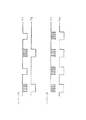
図3は本実施形態のスイッチ43Bによって発光される赤外光のタイミングチャートである。
【0036】
図3の7ー1に示すように、スイッチ43Bのペンアップ時には、変調された光と、変調されていない光が交互に発光するようになっている。また、7ー3に示すように、スイッチ43Bのペンダウン時には、常に変調された光が出力される。
【0037】
座標検出器1では、受光素子6で、この変調された光を検出し周波数検波部(後述)によって、この変調光のみを取り出す。取り出された変調光が、7−4に示すように、一定の時間内に連続している場合、ペンダウンと判定する。一方、取り出された変調光が、7ー2に示すように、間隔があいている場合、ペンアップと判定する。
【0038】
次に、スイッチ43Aによって発光される赤外光のタイミングチャートについて、図4を用いて説明する。
【0039】
図4は本実施形態のスイッチ43Aによって発光される赤外光のタイミングチャートである。
【0040】
スイッチ43Aによって発光される赤外光に含まれるスイッチ情報およびペンID情報は他の方法によって、座標検出器1で検出されている。これは、赤外光中にあるヘッダ部を設け、このヘッダ部が検出されたら、それに続く変調光のパターンによって、スイッチ43AのON、OFF、ペンID情報を判定する。この判定も、上述のような変調光、無変調をもって、0、1の状態を表現している。
【0041】
また、各状態の反転情報、例えば、SW1であれば/SW1の情報も対にして、送信しているため、判定間違いなどを防止することができる。
【0042】
尚、上記実施形態では、二つのスイッチしか設けていないが、これに限定されるものではなく、より多くのスイッチを搭載してもよい。また、各スイッチの役割は、ホストコンピュータ側のドライバなどによって再定義可能になっており、ユーザの使用形態にあったものを選べば良い。
<座標検出器1の詳細説明>
図5は本実施形態の座標検出器の詳細構成を示す図である。
【0043】
この座標検出器1には、集光光学系によって高感度に光量検出を行う受光素子6と、結像光学系によって光の到来方向を検出する4つのリニアセンサ20Xa,20Xb,20Ya,20Ybとが設けられている。そして、指示具4に内蔵された発光素子41からの光ビームにより、スクリーン10上に生成された光スポット5からの拡散光をそれぞれ受光する。
<集光光学系の動作説明>
受光素子6には、集光光学系としての集光レンズ6aが装着されており、スクリーン10上の全範囲から高感度で所定波長の光量を検知する。この検知出力は、周波数検波部71によって検波された後、制御信号検出部72において制御信号(指示具4の発光制御部42によって重畳された信号)などのデータを含むデジタル信号に復調される。
【0044】
また、本実施形態では、タイミング信号を送信するコード等の手段を有しないため、変調信号によってリニアセンサ20Xa,20Xb,20Ya,20Ybを制御することになる。また、後述するが、信号検出は、発光時と非発光時時の差分によって行う。そして、そのシャッタタイミングと発光タイミングをあわせるために、上記変調信号のタイミングを用いて、リニアセンサ20Xa,20Xb,20Ya,20Ybのリセット信号を発生させている。
【0045】
ここで、周波数検波部71で扱われる信号のタイミングチャートについて、図6を用いて説明する。
【0046】
図6は本実施形態で扱われる信号のタイミングチャートである。
【0047】
図6において、8−1がペンダウン時の変調信号を周波数検波部71で検波した後の信号IRである。このIR信号は、いわば、発光している期間をあらわしているため、リニアセンサ20Xa,20Xb,20Ya,20Ybのシャッタタイミングをこの信号に同期させる必要がある。
【0048】
一方、8−2が、リニアセンサ20Xa,20Xb,20Ya,20Ybのシャッタ周期をあらわすもので、L(ローレベル)の時に発光時の検出を行い、H(ハイレベル)の時に非発光時の検出を行うタイミングを示す信号IRCLKである。このIRCLK信号は、リニアセンサ20Xa,20Xb,20Ya,20Ybに供給されているクロックによって、リニアセンサ20Xa,20Xb,20Ya,20Ybから出力される。このIRCLK信号と、発光期間を同期させるために、8−1で示すIR信号が検出されたら、IR信号とIRCLK信号が同期する程度の一定量の遅延時間をもって、8ー3で示すリニアセンサ20Xa,20Xb,20Ya,20Ybにクリア(CLR)信号を出力する。
【0049】
このクリア動作によって、同期が可能になる。遅延量は、CLR信号が終了後、IRCLK信号がLOWになる時間によって、決定すればよい。
<結像光学系の動作説明>
図7はリニアセンサ20Xa,20Xb,20Ya,20Ybの配置関係を示す図である。
【0050】
図7において、結像光学系としての円筒レンズ90Xa,90Xb、90Ya,90Ybによって光スポット5の像が、リニアセンサ20Xa,20Xb,20Ya,20Ybの各センサの感光部21Xa、21Xb、21Ya、21Ybに線状に結像する。これらリニアセンサ20Xa,20Xb,20Ya,20Ybを正確に直角に配置することによって、それぞれがX座標、Y座標を反映した画素にピークを持つ出力が得られる。
【0051】
そして、これらリニアセンサ20Xa,20Xb,20Ya,20Ybは、センサ制御部31によって制御され、出力信号はセンサ制御部31に接続されたAD変換部31Aによってデジタル信号として座標演算部32に送られる。座標演算部32は、入力されたデジタル信号より出力座標値を計算し、その計算結果を制御信号検出部72からの制御信号などのデータと共に通信制御部33を介して、所定の通信方法で外部制御装置(不図示)に送出する。また、調整時など通常と異なる動作(例えば、ユーザ校正値の設定)を行わせる場合は、通信制御部33からセンサ制御部31、座標演算部32へモード切換信号が送られる。
【0052】
本発明では、光スポット5の像がリニアセンサ20Xa,20Xb,20Ya,20Ybの各センサの画素の数倍の像幅となるように焦点調節あるいは拡散フィルム等を用いて、故意にボケを生じさせている。但し、大きくぼけさせると、ピークレベルが小さくなってしまうので、数画素程度の像幅が最適である。画素数の少ないCCDを有するリニアセンサ20Xa,20Xb,20Ya,20Ybと、適度にボケた光学系を用いることが、本発明の特徴の一つであり、このような組み合わせを用いることによって、演算データ量が少なく、小さなセンサと光学系で非常に高分解能、高精度、高速でかつ低コストな座標入力装置を実現することができる。
【0053】
アレイ状に配置されたX座標検出用リニアセンサ20Xa,20Xb,Y座標検出用リニアセンサ20Ya,20Ybは同一の構成であり、その詳細構成について、図8を用いて説明する。
【0054】
図8は本実施形態のリニアセンサの詳細構成を示す図である。
【0055】
受光部であるセンサアレイ21はN個の画素(本実施形態では、64画素)からなり、受光量に応じた電荷が積分部22に貯えられる。積分部22は、N個からなり、ゲートICGに電圧を加えることによってリセットできるため、電子シャッタ動作が可能である。この積分部22に貯えられた電荷は、電極STにパルス電圧を加えることによって蓄積部23に転送される。この蓄積部23は、2N個からなり、指示具4の発光タイミングに同期したIRCLK信号のH(ハイレベル)とL(ローレベル)とにそれぞれ対応して別々に電荷が蓄積される。その後、光の点滅に同期して各々別々に蓄積された電荷は、転送クロックを簡単にするために設けられた2N個からなるシフト部24を介して、2N個からなるリニアCCD部25に転送される。
【0056】
これにより、リニアCCD部25には、N画素のセンサ出力の光の点滅に各々対応した電荷が隣接して並んで記憶されることになる。これらリニアCCD部25に並べられた電荷は、2N個からなるリングCCD部26に順次転送される。このリングCCD26は、CLR信号によってCLR部27で空にされた後、リニアCCD部25からの電荷を順次蓄積していく。
【0057】
このようにして蓄積された電荷は、アンプ29によって読み出される。このアンプ29は、非破壊で蓄積電荷量に比例した電圧を出力するものであり、実際には、隣接した電荷量の差分、すなわち、発光素子41の点灯時の電荷量から非点灯時の電荷量を差し引いた分の値を増幅して出力する。
【0058】
この時、得られるリニアセンサ20Xa,20Xb,20Ya,20Ybの出力波形の一例について、図9を用いて説明する。
【0059】
図9は本実施形態のリニアセンサの出力波形の一例を示す図である。
【0060】
図9中、Bの波形は発光素子41の点灯時の信号のみを読み出したときの波形であり、Aの波形は非点灯時の波形、すなわち、外乱光のみの波形である(図8に示したように、リングCCD26には、これらA,Bの波形に対応する画素の電荷が隣接して並んでいる)。アンプ29は、その隣接する電荷量の差分値(B−Aの波形)を非破壊増幅して出力することになるが、これにより、指示具4からの光のみの像の信号を得ることができ、外乱光(ノイズ)の影響を受けることなく安定した座標入力が可能となる。
【0061】
また、図9に示したB−Aの波形の最大値をPEAK値と定義すれば、光に対してリニアセンサ20Xa,20Xb,20Ya,20Ybの各リニアセンサが機能する蓄積時間を増大させれば、その時間に応じてPEAK値は増大する。換言すれば、IRCLK信号の1周期分の時間を単位蓄積時間とし、それを単位として蓄積回数nを定義すれば、蓄積回数nを増大させることでPEAK値は増大する。そして、このPEAK値が所定の大ささTH1に達したことを検出することで、常に一定した品位の出力波形を得ることができる。
【0062】
一方、外乱光が非常に強い場合、差分波形B−Aのピークが十分な大きさになる前に、リングCCD26の転送電荷が飽和してしまう恐れがある。このような場合を考慮して、リニアセンサ20Xa,20Xb,20Ya,20Ybの各リニアセンサにはスキム機能を有するSKIM部28が付設されている。SKIM部28は、非点灯信号のレベルを監視し、図10において、n回目のAnで信号レベルが所定の値を超えている場合(図中、一点鎖線)、一定量の電荷をA,Bの各画素から抜き取るようにする。これにより、次のn+1回目には、An+1に示すような波形となり、これを繰り返すことによって、非常に強い外乱光があっても飽和することなく、信号電荷の蓄積を続けることができる。
【0063】
従って、指示具4からの点滅光の光量が微弱であっても、多数回積分動作を継続することによって、十分な大きさの信号波形を得ることが可能になる。特に、指示具4に可視光域の発光源を用いる場合、表示画像の信号が重畳するので、前述したスキム機能と差分出力を用いることによって、非常にノイズの少ないシャープな波形を得ることが可能となる。
【0064】
次に、リングCCD26の出力制御におけるタイミングチャートについて、図11を用いて説明する。
【0065】
図11は本実施形態のリングCCDの出力制御におけるタイミングチャートである。
【0066】
まず、IR信号から一定遅延時間後のCLR信号によりすべての動作がクリアされる。このあと、指示具4による入力があると、CCDOUT信号のような検出信号が、積分動作によって大きくなる。そして、一定レベル(VTH)を超えると、コンパレータの出力CMPOUT信号が立ち下がりリングCCD26の積分動作を停止させる。センサ制御部31は、このCMPOUT信号が下がるとAD変換を開始する。AD変換期間は、ADSMPL信号で示したように、リングCCD26の画素出力すべてに対して行われる。
【0067】
上述のように、リングCCD26の出力が、一定レベルを超えない場合には、センサ制御部31は、クリアからの経過時間をカウントし、あらかじめ定めた一定時間を過ぎているような場合には、強制的にAD変換動作を行う。このようにしておけば、入力が小さい場合でも、一定サンプリング時間内に必ずサンプリングが行われるようになる。
【0068】
AD変換は、図12に示すようなタイミングで行われる。つまり、リングCCD26の出力であるCCDOUT信号は時間軸を拡大すると、図12のように画素単位の検出光レベルに応じた電圧で出力される。この信号を、サンプリングパルスSPのタイミングで画素毎にAD変換し、センサ制御部31は、そのレベルをメモリなどに記憶する。
【0069】
上記のような動作を、各座標軸に対応したリングCCD26のすべてに対して行い、後述の座標計算を行う。
【0070】
また、座標検出器1に到達する指示具4の光は、指示具4に内蔵された電源部(電池)44の消耗により変動する他、指示具4の姿勢によっても変動する。特に、スクリーン10の光拡散性が小さい楊合、表示画像の正面輝度は向上するが、この指示具4の姿勢による座標検出器1への入力光量の変動が大きくなってしまう。しかしながら、本発明では、このような場合であっても、積分回数が自動的に追従して常に安定した出力信号を得ることができるので、安定した座標検出が可能となる。
【0071】
以上説明したように、点滅光に高周波数のキャリアを加え、そのキャリアを周波数検波して得た所定周期の復調信号によって積分動作のタイミング制御を行うようにしたので、指示具と搬像部とをコードレスで同期させることができ、使い勝手の良い座標入力装置を実現することができる。また、積分部からの差分信号中のピークレベルを関しし、積分動作を停止させる積分制御手段を設けたので、光量が変化してもほぼ一定レベルの光スポット像の信号を作成でき、これにより、常に安定した高分解能な座標演算結果を得ることができる。
<座標値演算>
座標演算部32における座標演算処理について説明する。
【0072】
上述したようにして得られた4つのリニアセンサ20Xa,20Xb,20Ya,20Ybの出力信号(アンプ29からの差分信号)は、センサ制御部31に設けられたAD変換部31Aでデジタル信号として座標演算部32に送られ、座標値が演算される。座標値の演算は、まず、X座標、Y座標の各方向の出力に対して求める。尚、演算処理は、X座標、Y座標同様であるので、X座標値の演算についてのみ説明する。
【0073】
リニアセンサ20Xa,20Xbはそれぞれ、図13に示すように、スクリーン10の縦半分の検出領域として構成されており、その中央付近では、検出領域が重複している。
【0074】
リニアセンサ20Xaは、スクリーン10のSXa領域に光スポットがある場合に光を検出し、リニアセンサ20Xbはスクリーン10のSXb領域に光スポットがある場合に光を検出する。重複領城では、両センサで検出が行われる。その時のリニアセンサ20Xa,20Xbの出力について、図14を用いて説明する。
【0075】
図14はリニアセンサの出力を模式的に示す図である。
【0076】
中央の重なりの部分に光スポットがある場合には、15−1に示すように、リニアセンサ20Xa,20Xbともに出力が現れる。一方、SXb領域に光スポットがある場合には、15−2に示すように、リニアセンサ20Xbのみに出力が現れる。このように理想的に重複部分以外では、一方の出力がある場合には、例えば、一方の座標値を元に、その値が、基準点を超えたか否かで、切り換えの判定を行い、座標値を連結する。
【0077】
しかしながら、ノイズ、あるいは漏れ光、外乱光などによって、15−3に示すような本来の光スポット以外の所に、出力が生じる場合がある。
【0078】
このような時に、一方の座標値で判定を行っていると、間違った判定をしてしまい表示画面上で、いきなり違う点にカーソルなどが表示され、例えば、描画中であると、不要な線が引かれてしまうことになる。そこで、本発明では、得られたリニアセンサ20Xa,20Xb,20Ya,20Ybの出力のピーク値に基づいて、座標値の判定を行う。
次に、本実施形態の座標演算処理の処理フローについて、図15を用いて説明する。
【0079】
図15は本実施形態の座標演算処理の処理フローを示すフローチャートである。
【0080】
尚、リニアセンサ20Xa,20Xbの各リングCCD26の出力をDXa、DXbとする。この値は、先に説明したように、AD変換された値であるから、リングCCD26の各画素ごとの光検出量に応じた電圧値である。そこで、各データの最大値をもって、ピークレベルを決定することができる。
【0081】
また、リニアセンサ20Xa,20Xbで検出される座標を、それぞれCCDXa、CCDXbとする。
【0082】
まず、ステップS201で、任意の座標入力点での各画素の差分信号である差分データDXa(n)(本実施形態の場合、画素数n=64)が読み込まれ、バッファメモリ(不図示)に貯えられる。ステップS202で、このデータのピークレベルを求め、Xapとして記憶する。次に、ステップS203で、あらかじめ設定しておいた閾値Vと比較し、閾値以上のデータ値Exa(n)を算出する。このデータ値Exa(n)を用いて、ステップS204で、リニアセンサ20Xa上の座標CCDXaを算出する。本実施形態では、重心法により出力データの重心を算出しているが、出力データExa(n)のピーク値を求める方法(例えば、微分法による)等、計算の方法はこれに限定されないことは言うまでもない。
【0083】
同様にして、リニアセンサ20Xb上の座標CCDXbも算出する。
【0084】
これら算出された座標値は、リニアセンサ20Xa,20XbのそれぞれのリニアCCD26上での画素に対応した座標である。そのため、これらの座標値を連結することで一つのリニアセンサ20Xa,20Xb上での座標値として扱えるようになる。
【0085】
そこで、リニアセンサ20Xa,20XbのそれぞれのリニアCCD26上での画素に対応した座標値を連結するための基準座標を定義する。
【0086】
この基準座標の定義について、図16を用いて説明する。
【0087】
図16は本実施形態の基準座標の定義を説明するための図である。
【0088】
図16は、リニアセンサ20Xa,20XbのそれぞれのリニアCCD26の座標を概念的に配置した構成を示している。リニアセンサ20Xa,20Xbの検出領域は、先に説明したように重複部分を有しているため、その座標位置を重ねると、同図のようになる。
【0089】
この時、リニアセンサ20Xa,20XbのそれぞれのリニアCCD26が共に測定可能な領域で、基準点をあらかじめ定義する。つまり、スクリーン10上の重複部分に入力を行い、座標CCDXa,CCDXb(CCDXa_org,CCDXb_org)として読み込む。これらの値を、基準点データ(基準座標)として、EEPROM等の不揮発性メモリ(不図示)に記憶しておき、通常の使用時にはこの値を読み出して、座標値演算を行う。
【0090】
以下、これらの基準点データを用いて、リニアセンサ20Xa,20XbのそれぞれのリニアCCD26上での画素に対応した座標値を連結した連結座標CCDXの算出処理について、図17を用いて説明する。
【0091】
図17は本実施形態の連結座標CCDXの算出処理の処理フローを示すフローチャートである。
【0092】
まず、ステップS207で、リニアセンサ20Xa,20XbのそれぞれのリニアCCD26の基準点データ(CCDXa_org,CCDXb_org)をメモリから読み込む。ステップS208で、指示具4からの入力がなされた時に計算されるCCDXa、CCDXbの値と、基準点データの差分を算出する。これにより、図16の中央付近にある直線L1の点を原点としたリニアCCD上の座標に変換される。
【0093】
次に、ステップS209で、先に記憶しておいたリニアセンサ20Xa,20Xb各々のピークレベルXaP、XbPを比較する。通常、外乱光などによる信号は、正規の光スポットによる信号よりかなり小さいため、ピーク値の大きい方を正規の座標として採用する。このようにして、L1を境にリニアセンサ20Xa,20XbのそれぞれのリニアCCD26の両リニアCCDの座標値を連結できる。
【0094】
具体的には、ピークレベルXaPがピークレベルXbPより大きい場合(ステップS209でYES)、ステップS210に進み、CCDX=CCDXaとして、ステップS212に進む。一方、ピークレベルXaPがピークレベルXbP未満である場合(ステップS209でNO)、ステップS211に進み、CCDX=CCDXbとして、ステップS212に進む。
【0095】
そして、ステップS212で、スクリーン10上の座標値を一致させるために、上記の処理で得られたCCDXからスクリーン10上の座標値Xへの変換であるスクリーン座標計算を行う。尚、この処理の詳細については、後述する。
【0096】
以上の処理は、X座標について説明を行ったが、同様にして、Y座標についても行う。
【0097】
そして、上述のような演算処理によって算出した座標値(X,Y)を示すデータ信号は、座標演算部32から通信制御部33に送られる。この通信制御部33には、そのデータ信号と、制御信号検出部72からの制御信号とが入力される。そして、これらデータ信号および制御信号は、ともに所定の形式の通信信号に変換され、外部の表示制御装置に送出される。これにより、スクリーン10上のカーソルやメニュー、文字や線画の入力などの各種操作を行うことができる。
<基準点設定>
CCD座標値とスクリーン10上の座標値と一致させるためには、CCD座標値をスクリーン10上の座標値へ変換するための倍率、原点の座標値などの情報をあらかじめ、決定しておく必要がある。そのために、既知の複数の座標位置(基準点)のCCD座標を取得し、不揮発メモリ等に記憶する。
【0098】
図18は本実施形態の基準点の座標位置例を示す図である。
【0099】
まず、基準となる原点を設定する。その際には、同図P0位置に入力を行い、その時のCCD座標値を記憶する。この時、リニアセンサ20Xa,20Xb,20Ya,20Ybの重複部分を、この位置に設定しておけば、上述のようなリニアセンサ20Xa,20Xb,20Ya,20Ybの座標値を連結するための基準点入力を兼ねることも可能である。
【0100】
次に、原点にたいして、倍率決定のための入力を行う。実際には原点から既知の点一点の情報があれば倍率は計算可能である。
【0101】
しかしながら、レンズの収差、ばらつき等によって、入力位置(基準点)によって、倍率にばらつきが生じる。
【0102】
図19は本実施形態の基準点による倍率のばらつき例を示す図である。
【0103】
この図は、基準点のCCD座標値の出力を示している。
【0104】
例として、図18の基準点P0からP7間のCCD座標値の理論値は線形性のある直線状のデータ列となる。これに対し、基準点P0からP3間のCCD座標値の実測値は、理論値と同様、線形性にCCD座標値の出力が得られるが、基準点P7付近では、CCD座標値は線形性でなくなり、CCD座標値の理論値の直線状のデータ列からずれてしまうことがある。このような場合に、例えば、基準点P7で、倍率のためのデータを取得し、それを元に座標計算を行うと、全体的に誤差を生じてしまうことになる。
【0105】
そこで、倍率決定のためには、P3点などの、比較的、CCD座標値の理論値に近いCCD座標値の実測値を得ることができる基準点でのCCD座標値を用いる。
【0106】
上述してきたように、複数のリニアセンサ20Xa,20Xb,20Ya,20Ybを用いて連結して座標値を得るので、図18のように、各々リニアセンサ20Xa,20Xb,20Ya,20Ybの用いられる範囲は、図中Xa,Ya,Xb,Ybで示される領域になる。
【0107】
円筒レンズ90Xa,90Xb,90Ya,90Yb自体は、各リニアセンサ20Xa,20Xb,20Ya,20Ybに対して用意してあるので、結局、Xa,b、Yabそれぞれがばらつきを有することになる。
【0108】
そこで、各リニアセンサ20Xa,20Xb,20Ya,20Ybに対応した倍率を求める必要があり、そのために、基準点P3以外にも、基準点P1,P2,P4の各点でのリニアセンサ20Xa,20Xb,20Ya,20Ybの出力を記憶する。
【0109】
基準点P0が図18のように重複部分に存在するとすると、この点ではXab,Yabの各々の値が取得される。この時のリニアセンサ20Xa,20Xb,20Ya,20YbのCCDデータをP0Xa、P0Ya、P0Xb、P0Ybとする。基準点P0は原点であるので、この場合には、スクリーン10上の座標値は(X_P0,Y_P0)=(0,0)である。
【0110】
倍率の決定は、基準点P3を例にとり、基準点P3でのCCD座標をP3Xa、P3Yaとし、スクリーン10上の座標値をX_P3、Y_P3とした場合、倍率α3x、α3yは
α3x=(X_P3−X_P0)/(P3Xa−P0Xa) (1)
α3y=(Y_P3−Y_P0)/(P3Ya−P0Ya) (2)
で計算される。
【0111】
このように、各基準点に対して計算された倍率をもって、CCDX座標値に掛け合わせることでスクリーン10上の座標値を計算することができる。
【0112】
実際の計算では、まず、得られたCCDX、CCDY座標値から、領域判定を行い、各領域に対応した倍率α1、2、3、4を用いて計算を行う。
【0113】
このようにして、線形性の良い基準点での倍率を決定したが、図18のように、基準点P7付近(スクリーン10周辺部)では線形性が低下しているので、スクリーン10周辺部では誤差を生じることになる。
【0114】
実際の機器では、スクリーン10の有効投影範囲以外に余白となる部分が設定されるが、この領域が小さい場合には、入力がその部分で制限され、実際の投影範囲に入力できない部分が発生する可能性がある。
【0115】
通常のPC使用環境では、メニューバー等を画像周辺部へカーソルを移動することで、表示するような場合があり、このように、誤差が発生していると、その操作を阻害する可能性がある。
【0116】
そこで、倍率は、そのままに、スクリーン10周辺部への入力を可能とするために、基準点P5からP8までのCCD座標値を取得、記憶しておき、固定入力点のデータとする。ここで言う固定入力点とは、入力がその位置になされた場合、必ず、あらかじめ設定された点の座標を出力する点である。
【0117】
つまり、その固定入力点でのCCD座標が得られた場合には、倍率に関わらずスクリーン10上の固定の座標値を出力する。
【0118】
そのさい、その点だけを強制的に固定座標値にすると、急に座標値がかわってしまい、使用感を低下させるので、適当な点(例えば、基準点P7に対して基準点P3)のような点から、徐々に変化させる必要がある。
【0119】
ここで、座標系を図18の基準点P0から右をXプラス方向、基準点P0より下をYプラス方向とした場合に、得られたCCD座標値に倍率を乗じたものがX_P3より大きく、Y_P3より小さい場合、以下の式で重みを変えて、座標計算を行う。
【0120】

【0121】
また、上記式は、一例であり、より高次の式を用いても良い。
【0122】
以上のようにして、スクリーン10上の座標値と一致するCCD座標値を計算することができる。これは、図17のステップS212のスクリーン座標の計算処理に相当する。
【0123】
以下、図17のステップS212の処理の詳細について、図20を用いて説明する。
【0124】
図20は本実施形態のステップS212の処理の詳細を示すフローチャートである。
【0125】
まず、ステップS302で、不揮発メモリ等に記憶された基準点P0〜P8でのCCD座標値を読み込む。このCCD座標値と、スクリーン10上の基準点P0〜P8に対応する既知の座標値を用いて、式(1)、(2)を用いて倍率を計算する。
【0126】
ステップS304で、入力された各リニアセンサのCCD座標値を読み出す。次に、ステップS305で、読み出したCCD座標値を連結する。
【0127】
次に、ステップS306で、連結されたCCD座標値から、その座標値がスクリーン10上のどの象現に入るか判定する。これは、原点座標との比較で行えば良く、例えば、図18に示すように、第1象現をS1、以下各象現毎にS2,S3,S4とする。
【0128】
判定された象現によって、各々の象現の計算に振り分けられる。
【0129】
例えば、第1象限S1について説明すれば、ステップS311で、第1象限S1の倍率と連結されたCCD座標値を乗ずて、スクリーン座標を計算する。次に、ステップS315で、計算されたスクリーン座標が固定入力点となる固定エリアであるか否か判定する。この判定は、第1象限S1の場合では、上述したように、基準点P3の座標値で判定すれば良い。他の象現も同様にして判定すれば良い。
【0130】
ステップS315において、固定エリアでない場合(ステップS315でNO)、ステップS323に進み、その計算されたスクリーン座標を出力する。一方、固定エリアである場合(ステップS315でYES)、式(3)、(4)を用いて固定エリアに対するスクリーン座標を計算する。そして、ステップS323に進み、その計算されたスクリーン座標を出力する。座標送出後は、すでに倍率等は計算されてメモリに貯えられているので、再度、ステップS304に戻る。
【0131】
ここでは、第1象限S1について説明したが、他の象現でも用いる基準点の座標値が異なるだけで、演算方法は同様である。
【0132】
以上の様に、既知の基準点のCCD座標値を取得し、不揮発性メモリに記憶しておく。そして、記憶されたCCD座標値を用いて、原点、倍率、固定入力点を計算し座標計算を行うことで、より高精度の座標入力装置を提供可能になる。
【0133】
尚、複数の基準点のCCD座標値の取得は、既知の入力位置に入力できる治具を用いてもよいし、また、画面上で出荷時に設定することもできる。
【0134】
例えば、通信制御部33に対して、スクリーン10上の基準点の座標値を送信すると、ホストコンピュータ側のドライバがスクリーン10上のその位置にカーソルを表示する。そして、そのカーソル位置に対して、入力を行えば基準点のCCD座標値が得られる。順次、送出する座標値を変更して繰り返しこの処理を行えば、図21に示すごとく、9点の基準点のCCD座標値をホストコンピュータ側で入力することができる。
【0135】
図21は本実施形態の9点の基準点の座標値を入力する場合の処理を示すフローチャートである。
【0136】
ホストコンピュータでは、基準点取得モードに入ると、ステップS402で、CCD座標値を取得する基準点Pn(ここでは、n:1,2,…,8,9)に基準…P0のスクリーン10の座標値をセットする(ここでは説明を簡単にするため、X,Yに細かく分けて説明していないが、X,Y共にセットされている)。
【0137】
次に、ステップS403で、基準点PnにおけるCCD座標値の取得回数を計測するためのカウンタをクリアする。これは、基準点のCCD座標値をより精度良くするために、同一の基準点のCCD座標値を複数回取得し、その取得された複数のCCD座標値の平均値をその基準点のCCD座標値とするためである。また、この取得回数は、装置のノイズ等の状態に応じて、要求される精度に基づいて決定すればよい。
【0138】
次に、ステップS404で、先にセットした基準点の座標値を送出する。ステップS405で、その基準点に対するCCD座標を取得し、メモリに記憶する。ステップS407で、取得回数のカウンタをインクリメントする。ステップS408で、規定回数取得したか否かを判定する。
【0139】
規定回数に達していない場合(ステップS408でNO)、ステップS405に戻る。規定回数に達している場合(ステップS408でYES)、ステップS409に進み、同一の基準点に対して取得した複数のCCD座標値の平均を計算し、この平均のCCD座標値を各基準点毎に用意されたメモリに格納する。
【0140】
ステップS410で、処理対象が最後の基準点Pnであるか否かを判定する。最後の基準点Pnでない場合(ステップS410でNO)、ステップS411に進み、処理対象の基準点Pnを1インクリメントして、ステップS403に戻る。一方、最後の基準点Pnである場合(ステップS410でYES)、ステップS412で、得られた各基準点のCCD座標値を不揮発メモリに格納する。
【0141】
このような作業は、毎回電源投入時に行ってもよいが、ユーザの作業が煩雑になり、また、精度も確保できないので、一般的には出荷時に行う。
【0142】
しかしながら、この種のプロジェクタを用いた機器では、座標入力装置を構成する投射型表示装置8とスクリーン10間の距離を変更することで、簡単に、画面サイズの変更を行うことができる。つまり、出荷後にユーザの希望のサイズに画面サイズを変更することが可能になる。
【0143】
図22は本実施形態の画面サイズを変更した場合の座標値の関係を示す図である。
【0144】
投射型表示装置8から、通常であれば、10Aの位置でスクリーン10に画像が投影されている状態から、スクリーン10を10Bの位置に設定することで、より大画面の画像を得ることができる。
【0145】
この時、座標検出器1の位置が、投射型表示装置8の光軸上に設定されていない場合、10Aの位置でのスクリーン10上の場合には画像と一致していた状態が、10Bの位置でのスクリーン10上では点A’,B’,C’の位置をおのおの点A、B、Cの位置と計算してしまうため、実際の入力点と表示とがずれてしまうことになる。
【0146】
このずれを防止するために、あらかじめ、10Bの位置にスクリーン10が設定されている場合に、出荷時に記憶した基準点とスクリーン10の配置位置毎のCCD座標値を対応づけて記憶しておくことで、基準点を共通にしつつ、スクリーン10の位置が変更された場合にも適切に座標値を計算することができる。
【0147】
図23は本実施形態の画面サイズが変更された場合の座標値の計算概念を示す図であるである。
【0148】
10Aの位置のスクリーン10の点Aに表示される画像が、10Bの位置のスクリーン10上で点aに表示されるとすると、点aは座標検出器1からは10Aの位置のスクリーン10の点A”に相当する。同様に、点bが点B”、点cが点C”となる。
【0149】
このように、上述のような9点の基準点を入力する場合に対して、2つのスクリーン座標値を設定しておく。
【0150】
つまり、基準点のP3Xに対する座標値として、10Aの位置のスクリーン10における座標値がX0_P3と、10Bの位置のスクリーン10における座標値がX1_P3として、各位置毎の基準点の座標値をそれぞれメモリに記憶しておく。
【0151】
このように、複数種類のある位置毎のスクリーン10の座標値を選択する場合には、例えば、座標検出器1にスイッチ80(図5)を設け、スイッチのON/OFFで選択するようにすれば良い。例えば、スイッチ80がOFFの場合には、10Aの位置のスクリーン10の座標値を用いて座標計算を行う。また、スイッチ80がONの場合には、10Bの位置のスクリーン10の座標値を、10Aの位置へ写像した座標値を用いて座標計算を行う。但し、この時、複数のリニアセンサのCCD座標値を連結するための基準点が基準点P0と一致しているとすると、連結されたCCD座標は、実際の入力位置に対してずれたものになる。このずれ(オフセット)は、基準点P0の投影位置相当が含まれるので、10Bの位置のスクリーン10の状態での座標計算では、このオフセット分を調整する必要がある。
【0152】
以下、このオフセット分を調整する場合のスクリーン座標の計算処理について、図24を用いて説明する。
【0153】
図24は本実施形態のオフセット分を調整する場合のスクリーン座標の計算処理を示すフローチャートである。
【0154】
尚、このフローチャートでは、説明を簡単にするために、図20で説明した象現の判定は割愛する。また、図22及び図23の10Aの位置を通常位置として、この座標系をY0座標系として、これに対し、10Bの位置をY1座標系とする。また、ここでは、2つの座標系を示しているが、これに限定されるものではなく、複数種類の位置に応じた座標系を構成できることは言うまでもない。
【0155】
まず、ステップS502で、不揮発メモリ等に記憶された基準点のCCD座標値を読み込む。次に、ステップS503で、座標検出器1のスイッチ80の状態を読み込み、スイッチ80の状態がONであるか否かを判定する。つまり、Y0座標系であるかY1座標系であるかを判定する。スイッチ80の状態がOFFである場合(ステップS504でNO)、ステップS505に進み、通常の計算として、オフセット値としてレジスタOFFSET=Y0_P0(0)を書き込む。そして、ステップS506で、通常のY0座標系で倍率計算を行う。
【0156】
一方、スイッチ80がONである場合(ステップS504でYES)、ステップS505に進み、オフセット値としてレジスタOFFSET=Y1_P0を書き込む。そして、ステップS507で、Y1座標系で倍率計算を行う。
【0157】
次に、ステップS508で、入力された各リニアセンサのCCD座標値を読み出す。次に、ステップS509で、読み出したCCD座標値を連結する。
【0158】
次に、ステップS510で、計算された倍率と連結されたCCD座標値を乗じて、スクリーン座標を計算する。ここで計算されるスクリーン座標は、上述したようにオフセットが含まれているので、ステップS511で、レジスタOFFSETに書き込まれている値を加算して、オフセットの補正を行う。尚、ここでは、スクリーン座標系のスクリーン座標を計算してからオフセットの補正を行っているが、基準点P0のオフセットをCCD座標値に換算して補正しても良い。
【0159】
次に、ステップS512で、座標検出器1のスイッチ80の状態を読み込み、スイッチ80の状態がONであるか否かを判定する。スイッチ80の状態がOFFである場合(ステップS512でNO)、ステップS513に進む。次に、ステップS513で、計算されたスクリーン座標が固定入力点となる固定エリアであるか否か判定する。ステップS513において、固定エリアでない場合(ステップS513でNO)、ステップS517に進み、その計算されたスクリーン座標を出力する。一方、固定エリアである場合(ステップS513でYES)、ステップS515に進み、Y0座標系を使用して固定エリアに対するスクリーン座標を計算する。そして、ステップS517に進み、その計算されたスクリーン座標を出力する。座標送出後は、すでに倍率等は計算されてメモリに貯えられているので、再度、ステップS508に戻る。
【0160】
一方、ステップS512で、スイッチ80の状態がONである場合(ステップS512でYES)、次に、ステップS514で、計算されたスクリーン座標が固定入力点となる固定エリアであるか否か判定する。ステップS514において、固定エリアでない場合(ステップS514でNO)、ステップS517に進み、その計算されたスクリーン座標を出力する。一方、固定エリアである場合(ステップS514でYES)、ステップS515に進み、Y1座標系を使用して固定エリアに対するスクリーン座標を計算する。そして、ステップS517に進み、その計算されたスクリーン座標を出力する。座標送出後は、すでに倍率等は計算されてメモリに貯えられているので、再度、ステップS508に戻る。
【0161】
以上説明したように、本実施形態によれば、スクリーンの配置位置毎に、既知の基準点のCCD座標値を不揮発性メモリに記憶しておき、スクリーンの位置に対応するCCD座標値からCCD座標値から最終的なスクリーン10上の座標値を得るための原点、倍率、固定点を算出し、座標演算を行うことで、高精度な座標入力装置を提供可能になると共に、スクリーンの位置が変更された場合にも、常に、適切な基準点のCCD座標値を用いた高精度の座標演算が可能になる。
【0162】
尚、本発明の目的は、前述した実施形態の機能を実現するソフトウェアのプログラムコードを記録した記憶媒体を、システムあるいは装置に供給し、そのシステムあるいは装置のコンピュータ(またはCPUやMPU)が記憶媒体に格納されたプログラムコードを読出し実行することによっても、達成されることは言うまでもない。
【0163】
この場合、記憶媒体から読出されたプログラムコード自体が前述した実施形態の機能を実現することになり、そのプログラムコードを記憶した記憶媒体は本発明を構成することになる。
【0164】
プログラムコードを供給するための記憶媒体としては、例えば、フロッピディスク、ハードディスク、光ディスク、光磁気ディスク、CD−ROM、CD−R、磁気テープ、不揮発性のメモリカード、ROMなどを用いることができる。
【0165】
また、コンピュータが読出したプログラムコードを実行することにより、前述した実施形態の機能が実現されるだけでなく、そのプログラムコードの指示に基づき、コンピュータ上で稼働しているOS(オペレーティングシステム)などが実際の処理の一部または全部を行い、その処理によって前述した実施形態の機能が実現される場合も含まれることは言うまでもない。
【0166】
更に、記憶媒体から読出されたプログラムコードが、コンピュータに挿入された機能拡張ボードやコンピュータに接続された機能拡張ユニットに備わるメモリに書込まれた後、そのプログラムコードの指示に基づき、その機能拡張ボードや機能拡張ユニットに備わるCPUなどが実際の処理の一部または全部を行い、その処理によって前述した実施形態の機能が実現される場合も含まれることは言うまでもない。
【0167】
本発明を上記記憶媒体に適用する場合、その記憶媒体には、先に説明した図15、図17、図20、図21及び図24に示すフローチャートに対応するプログラムコードが格納されることになる。
【0168】
【発明の効果】
以上説明したように、本発明によれば、高精度の座標入力装置及びその制御方法、コンピュータ可読メモリを提供できる。
【図面の簡単な説明】
【図1】本実施形態の座標入力装置の概略構成を示す図である。
【図2】本実施形態の指示具の詳細構成を示す図である。
【図3】本実施形態のスイッチ43Bによって発光される赤外光のタイミングチャートである。
【図4】本実施形態のスイッチ43Aによって発光される赤外光のタイミングチャートである。
【図5】本実施形態の座標検出器の詳細構成を示す図である。
【図6】本実施形態で扱われる信号のタイミングチャートである。
【図7】リニアセンサ20Xa,20Xb,20Ya,20Ybの配置関係を示す図である。
【図8】本実施形態のリニアセンサの詳細構成を示す図である。
【図9】本実施形態のリニアセンサの出力波形の一例を示す図である。
【図10】本実施形態のリニアセンサのスキム動作を説明するための出力波形の一例を示す図である。
【図11】本実施形態のリングCCDの出力制御におけるタイミングチャートである。
【図12】本実施形態のAD変換のタイミングチャートである。
【図13】本実施形態のリニアセンサの構成を示す図である。
【図14】リニアセンサの出力を模式的に示す図である。
【図15】本実施形態の座標演算処理の処理フローを示すフローチャートである。
【図16】本実施形態の基準座標の定義を説明するための図である。
【図17】本実施形態の連結座標CCDXの算出処理の処理フローを示すフローチャートである。
【図18】本実施形態の基準点の座標位置例を示す図である。
【図19】本実施形態の基準点による倍率のばらつき例を示す図である。
【図20】本実施形態のステップS212の処理の詳細を示すフローチャートである。
【図21】本実施形態の9点の基準点の座標値を入力する場合の処理を示すフローチャートである。
【図22】本実施形態の画面サイズを変更する場合の座標値の関係を示す図である。
【図23】本実施形態の画面サイズが変更された場合の座標値の計算概念を示す図であるである。
【図24】本実施形態のオフセット分を調整する場合のスクリーン座標の計算処理を示すフローチャートである。
【符号の説明】
1 座標検出器
2 座標検出センサ部
3 コントローラ
4 指示具
5 光スポット
6 受光素子
6a 集光レンズ
7 信号処理部
8 投射型表示装置
81 画像信号処理部
82 液晶パネル
83 ランプ
84 ミラー
85 コンデンサーレンズ
86 投影レンズ
20Xa、20Xb、20Ya、20Yb リニアセンサ
21 センサアレイ
22 積分部
23 シフト部
24 蓄積部
25 リニアCCD
26 リングCCD
27 クリア部
28 スキム部
29 アンプ
31 センサ制御部
31A AD変換部
32 座標演算部
33 通信制御部
71 周波数検波部
72 制御信号検出部[0001]
BACKGROUND OF THE INVENTION
The present invention generates a light spot by irradiating the coordinate input screen with light from the pointing tool, generates coordinates corresponding to the light spot, and includes a projection type display unit that displays an image on the coordinate input screen. The present invention relates to an input device, a control method thereof, and a computer-readable memory.
[0002]
[Prior art]
As a conventional coordinate input device, a CCD area sensor or linear sensor is used to image a light spot, and image processing such as using barycentric coordinates or pattern matching is performed to calculate and output coordinate values. In addition, a device using a position detection element called PSD (analog device that can obtain an output voltage corresponding to the spot position) is known.
[0003]
For example, Japanese Examined Patent Publication No. 7-76902 discloses an apparatus that captures a light spot by a parallel beam of visible light with a video camera to detect coordinates, and simultaneously transmits and receives a control signal with infrared diffused light. Japanese Patent Application Laid-Open No. 6-274266 discloses an apparatus for performing coordinate detection using a linear CCD sensor and a special optical mask.
[0004]
On the other hand, Japanese Patent No. 2503182 discloses a configuration and output coordinate correction method for an apparatus using PSD.
[0005]
[Problems to be solved by the invention]
In recent years, large screen displays have been increased in screen size and resolution at the same time as the brightness is improved. For this reason, it is necessary to improve the resolution of the coordinate input device.
[0006]
In recent years, large screen displays have been increased in screen size and resolution at the same time as the brightness is improved. For this reason, it is necessary to improve the resolution of the coordinate input device.
[0007]
Conventionally, as a coordinate input device of this type, as described in JP-A-11-219253, as a main configuration, an indicator that forms a light spot on a screen that is a coordinate input surface, and a
[0008]
In this coordinate input device, a cylindrical lens or the like is arranged in front of the ring CCD, and the entire input screen is input to the ring CCD.
[0009]
For example, with respect to CCD pixels arranged linearly on the X axis, light input to the same X coordinate via a cylindrical lens is input through different paths depending on the location. At this time, an error may occur in the coordinate value detected by the CCD pixel, for example, due to the aberration of the lens or the variation between solids, the imaging position may be different, or the intensity distribution of the input light may be different. . On the other hand, high accuracy can be achieved by storing the CCD output values of known points of a plurality of coordinate values on the screen in a nonvolatile memory and performing coordinate calculation based on the CCD output values. it can.
[0010]
Also, with this type of coordinate input device, the screen size can be easily changed by changing the distance between the projection display device and the screen, so the screen size can be changed after factory shipment as a user option. is there.
[0011]
In such a case, it is good if the projection display device of the coordinate input device and the optical axis of the coordinate detector match, but if the optical axes of the two do not match, they are stored in the non-volatile memory. If the coordinate calculation is performed using the CCD output value, a significant shift occurs in the coordinate value.
[0012]
The present invention has been made in view of the above problems, and an object thereof is to provide a highly accurate coordinate input device, a control method thereof, and a computer-readable memory.
[0013]
[Means for Solving the Problems]
In order to achieve the above object, a coordinate input device according to the present invention comprises the following arrangement. That is,
From the indicator screen By detecting the light irradiated to the coordinate detector, screen Generates a coordinate output signal corresponding to the light irradiation position The image information corresponding to the coordinate output signal is displayed on the screen by the projection display device, and the screen size of the screen is changed by changing the distance between the projection display device and the screen. Possible coordinate input device,
Said screen Multiple different screen sizes as output information of the coordinate detector obtained by irradiating the light to a predetermined position on The position of the screen relative to each Storage means for storing each coordinate value;
Arbitrary screen size among the plurality of different screen sizes Position of the screen relative to A selection means for selecting
Selected by the selection means Position of the screen Based on the coordinate values stored in the storage means corresponding to screen A computing means for computing the irradiation position of the light above;
Is provided.
[0014]
Preferably, the calculation means is selected by the selection means. Corresponds to the position of the screen Coordinate value To obtain the coordinate value on the screen calculated from Based on the origin, said screen The above irradiation position of the light is calculated.
[0015]
Preferably, the coordinate detector includes the coordinate detector. screen Composed of a plurality of pixels corresponding to the coordinate values in
The calculation means is configured to input the input at the origin and the reference point. screen By multiplying the magnification determined from the ratio of the difference between the coordinate values at the origin and the difference between the coordinate values of the pixels at the origin and the reference point by the coordinate values of the pixels detected by the coordinate detector. The irradiation position is calculated.
[0016]
Preferably, the computing means is the screen The irradiation position of the light on the screen It is determined whether the relationship between the upper coordinate value and the coordinate value of the pixel is a non-linear fixed input area, based on the determination result, screen The above irradiation position of the light is calculated.
[0017]
Preferably, the apparatus further comprises output means for outputting coordinate information of a predetermined position on the coordinate input screen corresponding to the position designated by the designation means to an external device,
The storage means stores an output of the coordinate detector obtained by irradiation performed based on the coordinate information as an output of the coordinate detector corresponding to the position designated by the designation means.
[0018]
In order to achieve the above object, a method for controlling a coordinate input device according to the present invention comprises the following arrangement. That is,
From the indicator screen By detecting the light irradiated to the coordinate detector, screen Generates a coordinate output signal corresponding to the light irradiation position The image information corresponding to the coordinate output signal is displayed on the screen by the projection display device, and the screen size of the screen is changed by changing the distance between the projection display device and the screen. A control method of a possible coordinate input device,
Said screen Multiple different screen sizes as output information of the coordinate detector obtained by irradiating the light to a predetermined position on The position of the screen relative to each A storage step of storing each coordinate value in a storage medium;
Arbitrary screen size among the plurality of different screen sizes Position of the screen relative to A selection process for selecting
Selected in the selection process Position of the screen Based on the coordinate values stored in the storage medium corresponding to screen A calculation step of calculating the irradiation position of the light on
Is provided.
[0019]
In order to achieve the above object, a computer readable memory according to the present invention comprises the following arrangement. That is,
From the indicator screen By detecting the light irradiated to the coordinate detector, screen Generates a coordinate output signal corresponding to the light irradiation position The image information corresponding to the coordinate output signal is displayed on the screen by the projection display device, and the screen size of the screen can be changed by changing the distance between the projection display device and the screen. A computer readable memory storing a program for causing a computer to execute control of a coordinate input device,
Said screen Multiple different screen sizes as output information of the coordinate detector obtained by irradiating the light to a predetermined position on The position of the screen relative to each A storage step of storing each coordinate value in a storage medium;
Arbitrary screen size among the plurality of different screen sizes Position of the screen relative to A selection process for selecting
Selected in the selection process Position of the screen Based on the coordinate values stored in the storage medium corresponding to screen A calculation step of calculating the irradiation position of the light on
A computer-readable memory storing a program for causing a computer to execute the program.
[0020]
DETAILED DESCRIPTION OF THE INVENTION
Hereinafter, embodiments of the present invention will be described in detail with reference to the drawings.
[0021]
First, a schematic configuration of an optical coordinate input device according to the present invention will be described with reference to FIG.
[0022]
FIG. 1 is a diagram showing a schematic configuration of a coordinate input apparatus according to the present embodiment.
[0023]
This coordinate input device is roughly divided into an
[0024]
The coordinate
[0025]
The
[0026]
With this configuration, character information or line drawing information is input on the
<Detailed description of the
FIG. 2 is a diagram showing a detailed configuration of the pointing tool of the present embodiment.
[0027]
The
[0028]
The operator holds the
[0029]
The
[0030]
On the host computer side, for example, when the switch information of the switch 43B is received, it is determined that the pen is down, and the same operation as the left button operation of the mouse used in the DOS / V machine is performed. In the case of a drawing program or the like, a line or the like can be drawn in this state. Further, the
[0031]
The issuing
[0032]
The light emission time may be determined in view of the lifetime of the power source, and for example, a sufficient feeling of use can be given with a light emission time of several tens of seconds.
[0033]
In the present embodiment, the switch information is superimposed on the infrared light by two types of methods. In particular, since the switch information of the switch 43B is updated relatively frequently, it is expressed by the presence or absence of modulation of infrared light.
[0034]
Next, a timing chart of infrared light emitted by the switch 43B will be described with reference to FIG.
[0035]
FIG. 3 is a timing chart of infrared light emitted by the switch 43B of this embodiment.
[0036]
As indicated by reference numeral 7-1 in FIG. 3, when the switch 43B is pen-up, modulated light and non-modulated light are alternately emitted. Further, as indicated by 7-3, when the switch 43B is pen-down, the modulated light is always output.
[0037]
In the coordinate
[0038]
Next, a timing chart of infrared light emitted by the
[0039]
FIG. 4 is a timing chart of infrared light emitted by the
[0040]
The switch information and the pen ID information included in the infrared light emitted by the
[0041]
In addition, since inversion information of each state, for example, information of / SW1 in the case of SW1 is also transmitted in pairs, a determination error or the like can be prevented.
[0042]
In the above embodiment, only two switches are provided. However, the present invention is not limited to this, and more switches may be mounted. Also, the role of each switch can be redefined by the driver on the host computer side, etc., and what is appropriate for the usage pattern of the user can be selected.
<Detailed description of the coordinate
FIG. 5 is a diagram showing a detailed configuration of the coordinate detector of the present embodiment.
[0043]
The coordinate
<Description of the operation of the condensing optical system>
The
[0044]
In the present embodiment, since there is no means such as a code for transmitting the timing signal, the linear sensors 20Xa, 20Xb, 20Ya, and 20Yb are controlled by the modulation signal. As will be described later, signal detection is performed based on a difference between light emission and non-light emission. In order to match the shutter timing with the light emission timing, reset signals of the linear sensors 20Xa, 20Xb, 20Ya, and 20Yb are generated using the timing of the modulation signal.
[0045]
Here, a timing chart of signals handled by the
[0046]
FIG. 6 is a timing chart of signals handled in this embodiment.
[0047]
In FIG. 6, reference numeral 8-1 denotes a signal IR after the modulation signal at the pen-down time is detected by the
[0048]
On the other hand, 8-2 represents the shutter cycle of the linear sensors 20Xa, 20Xb, 20Ya, and 20Yb, and detects light emission when L (low level) and detection when no light emission when H (high level). This is a signal IRCLK indicating the timing to perform the operation. The IRCLK signal is output from the linear sensors 20Xa, 20Xb, 20Ya, and 20Yb by a clock supplied to the linear sensors 20Xa, 20Xb, 20Ya, and 20Yb. In order to synchronize the IRCLK signal with the light emission period, when the IR signal indicated by 8-1 is detected, the linear sensor 20Xa indicated by 8-3 has a certain amount of delay time to the extent that the IR signal and the IRCLK signal are synchronized. , 20Xb, 20Ya, 20Yb, a clear (CLR) signal is output.
[0049]
This clear operation enables synchronization. The amount of delay may be determined by the time that the IRCLK signal becomes LOW after the CLR signal ends.
<Description of operation of imaging optical system>
FIG. 7 is a diagram showing an arrangement relationship of the linear sensors 20Xa, 20Xb, 20Ya, and 20Yb.
[0050]
In FIG. 7, an image of the
[0051]
The linear sensors 20Xa, 20Xb, 20Ya, and 20Yb are controlled by the sensor control unit 31, and an output signal is sent to the coordinate
[0052]
In the present invention, defocusing is intentionally caused by using a focus adjustment or a diffusion film so that the image of the
[0053]
The X coordinate detection linear sensors 20Xa and 20Xb and the Y coordinate detection linear sensors 20Ya and 20Yb arranged in an array have the same configuration, and a detailed configuration thereof will be described with reference to FIG.
[0054]
FIG. 8 is a diagram showing a detailed configuration of the linear sensor of the present embodiment.
[0055]
The
[0056]
As a result, the
[0057]
The charge accumulated in this way is read out by the
[0058]
An example of output waveforms of the linear sensors 20Xa, 20Xb, 20Ya, and 20Yb obtained at this time will be described with reference to FIG.
[0059]
FIG. 9 is a diagram illustrating an example of an output waveform of the linear sensor of the present embodiment.
[0060]
In FIG. 9, a waveform B is a waveform when only a signal at the time of lighting of the
[0061]
Further, if the maximum value of the B-A waveform shown in FIG. 9 is defined as a PEAK value, the accumulation time during which the linear sensors 20Xa, 20Xb, 20Ya, and 20Yb function with respect to light can be increased. The PEAK value increases with the time. In other words, if the time for one cycle of the IRCLK signal is defined as a unit accumulation time and the number of accumulations n is defined as a unit, the PEAK value increases by increasing the number of accumulations n. Then, by detecting that the PEAK value has reached a predetermined magnitude TH1, it is possible to always obtain an output waveform with a constant quality.
[0062]
On the other hand, when the disturbance light is very strong, the transfer charge of the
[0063]
Therefore, even if the amount of flashing light from the
[0064]
Next, a timing chart in the output control of the
[0065]
FIG. 11 is a timing chart in the output control of the ring CCD of this embodiment.
[0066]
First, all operations are cleared by the CLR signal after a certain delay time from the IR signal. Thereafter, when there is an input from the
[0067]
As described above, when the output of the
[0068]
The AD conversion is performed at a timing as shown in FIG. That is, when the time axis is expanded, the CCDOUT signal that is the output of the
[0069]
The operation as described above is performed for all the
[0070]
Further, the light of the
[0071]
As described above, since the high-frequency carrier is added to the flashing light, and the timing control of the integration operation is performed by the demodulated signal of a predetermined period obtained by frequency detection of the carrier, the indicator, the carrying unit, Can be synchronized cordlessly, and an easy-to-use coordinate input device can be realized. In addition, with regard to the peak level in the difference signal from the integration unit, an integration control means for stopping the integration operation is provided, so that a light spot image signal having a substantially constant level can be created even if the light quantity changes. Therefore, a stable and high-resolution coordinate calculation result can be obtained.
<Coordinate value calculation>
A coordinate calculation process in the coordinate
[0072]
The output signals (difference signals from the amplifier 29) of the four linear sensors 20Xa, 20Xb, 20Ya, and 20Yb obtained as described above are coordinate-calculated as digital signals by the
[0073]
Each of the linear sensors 20Xa and 20Xb is configured as a vertical half detection area of the
[0074]
The linear sensor 20Xa detects light when there is a light spot in the SXa region of the
[0075]
FIG. 14 is a diagram schematically showing the output of the linear sensor.
[0076]
When there is a light spot at the overlapping portion in the center, as shown in 15-1, outputs appear in both the linear sensors 20Xa and 20Xb. On the other hand, when there is a light spot in the SXb region, an output appears only in the linear sensor 20Xb as shown in 15-2. In this way, when there is one output other than ideally overlapped part, for example, based on the coordinate value of one, switching determination is performed depending on whether the value exceeds the reference point, and the coordinate Concatenate values.
[0077]
However, there is a case where an output is generated in a place other than the original light spot as shown in 15-3 due to noise, leakage light, disturbance light, or the like.
[0078]
In such a case, if a determination is made with one coordinate value, an incorrect determination is made and a cursor is suddenly displayed at a different point on the display screen. Will be drawn. Therefore, in the present invention, the coordinate value is determined based on the peak values of the outputs of the obtained linear sensors 20Xa, 20Xb, 20Ya, and 20Yb.
Next, the process flow of the coordinate calculation process of this embodiment is demonstrated using FIG.
[0079]
FIG. 15 is a flowchart showing the processing flow of the coordinate calculation processing of this embodiment.
[0080]
The outputs of the
[0081]
Also, the coordinates detected by the linear sensors 20Xa and 20Xb are CCDXa and CCDXb, respectively.
[0082]
First, in step S201, difference data DXa (n) (in this embodiment, the number of pixels n = 64) that is a difference signal of each pixel at an arbitrary coordinate input point is read and stored in a buffer memory (not shown). Stored. In step S202, the peak level of this data is obtained and stored as Xap. Next, in step S203, a data value Exa (n) equal to or greater than the threshold value is calculated by comparison with a preset threshold value V. Using this data value Exa (n), the coordinate CCDXa on the linear sensor 20Xa is calculated in step S204. In the present embodiment, the centroid of the output data is calculated by the centroid method, but the calculation method such as a method of obtaining the peak value of the output data Exa (n) (for example, by the differential method) is not limited to this. Needless to say.
[0083]
Similarly, the coordinate CCDXb on the linear sensor 20Xb is also calculated.
[0084]
These calculated coordinate values are coordinates corresponding to the pixels on the
[0085]
Therefore, reference coordinates for connecting coordinate values corresponding to the pixels on the
[0086]
The definition of the reference coordinates will be described with reference to FIG.
[0087]
FIG. 16 is a diagram for explaining the definition of the reference coordinates of the present embodiment.
[0088]
FIG. 16 shows a configuration in which the coordinates of the
[0089]
At this time, a reference point is defined in advance in an area where the
[0090]
Hereinafter, the calculation processing of the connected coordinate CCDX in which the coordinate values corresponding to the pixels on the
[0091]
FIG. 17 is a flowchart showing the processing flow of the calculation processing of the connected coordinate CCDX of this embodiment.
[0092]
First, in step S207, the reference point data (CCDXa_org, CCDXb_org) of the
[0093]
Next, in step S209, the peak levels XaP and XbP of the linear sensors 20Xa and 20Xb stored in advance are compared. Usually, a signal due to disturbance light or the like is considerably smaller than a signal due to a normal light spot, and therefore, the one having a larger peak value is adopted as a normal coordinate. In this way, the coordinate values of both linear CCDs of the
[0094]
Specifically, when the peak level XaP is larger than the peak level XbP (YES in step S209), the process proceeds to step S210, and CCDX = CCDXa is set, and the process proceeds to step S212. On the other hand, if the peak level XaP is less than the peak level XbP (NO in step S209), the process proceeds to step S211 and CCDX = CCDXb, and the process proceeds to step S212.
[0095]
In step S212, in order to make the coordinate values on the
[0096]
Although the above processing has been described for the X coordinate, the same processing is also performed for the Y coordinate.
[0097]
Then, a data signal indicating the coordinate value (X, Y) calculated by the arithmetic processing as described above is sent from the coordinate
<Reference point setting>
In order to make the CCD coordinate value coincide with the coordinate value on the
[0098]
FIG. 18 is a diagram illustrating an example of the coordinate position of the reference point according to the present embodiment.
[0099]
First, a reference origin is set. At that time, an input is made at the position P0 in the figure, and the CCD coordinate value at that time is stored. At this time, if the overlapping portion of the linear sensors 20Xa, 20Xb, 20Ya, and 20Yb is set at this position, the reference point input for connecting the coordinate values of the linear sensors 20Xa, 20Xb, 20Ya, and 20Yb as described above is used. It is also possible to serve as.
[0100]
Next, input for determining the magnification is performed with respect to the origin. Actually, the magnification can be calculated if there is information of one known point from the origin.
[0101]
However, the magnification varies depending on the input position (reference point) due to lens aberration, variation, and the like.
[0102]
FIG. 19 is a diagram showing an example of variation in magnification according to the reference point of the present embodiment.
[0103]
This figure shows the output of the CCD coordinate value of the reference point.
[0104]
As an example, the theoretical value of the CCD coordinate value between the reference points P0 to P7 in FIG. 18 is a linear data string having linearity. On the other hand, the measured value of the CCD coordinate value between the reference points P0 to P3 can be output linearly as in the case of the theoretical value, but the CCD coordinate value is linear in the vicinity of the reference point P7. In some cases, the linear data string of the theoretical values of the CCD coordinate values may deviate. In such a case, for example, if data for the magnification is acquired at the reference point P7 and coordinate calculation is performed based on the data, an error will be generated as a whole.
[0105]
Therefore, in order to determine the magnification, the CCD coordinate value at a reference point that can obtain an actual measurement value of the CCD coordinate value that is relatively close to the theoretical value of the CCD coordinate value, such as the P3 point, is used.
[0106]
As described above, since coordinate values are obtained by using a plurality of linear sensors 20Xa, 20Xb, 20Ya, and 20Yb, the ranges in which the linear sensors 20Xa, 20Xb, 20Ya, and 20Yb are used as shown in FIG. In the figure, the region is indicated by Xa, Ya, Xb, Yb.
[0107]
Since the cylindrical lenses 90Xa, 90Xb, 90Ya, and 90Yb themselves are prepared for the respective linear sensors 20Xa, 20Xb, 20Ya, and 20Yb, eventually, Xa, b, and Yab have variations.
[0108]
Therefore, it is necessary to obtain the magnification corresponding to each of the linear sensors 20Xa, 20Xb, 20Ya, and 20Yb. For that reason, in addition to the reference point P3, the linear sensors 20Xa, 20Xb, The outputs of 20Ya and 20Yb are stored.
[0109]
If the reference point P0 exists in the overlapping portion as shown in FIG. 18, the values of Xab and Yab are acquired at this point. The CCD data of the linear sensors 20Xa, 20Xb, 20Ya, and 20Yb at this time are P0Xa, P0Ya, P0Xb, and P0Yb. Since the reference point P0 is the origin, in this case, the coordinate value on the
[0110]
The magnification is determined by taking the reference point P3 as an example. If the CCD coordinates at the reference point P3 are P3Xa and P3Ya and the coordinate values on the
α3x = (X_P3-X_P0) / (P3Xa-P0Xa) (1)
α3y = (Y_P3-Y_P0) / (P3Ya−P0Ya) (2)
Calculated by
[0111]
Thus, the coordinate value on the
[0112]
In actual calculation, first, region determination is performed from the obtained CCDX and CCDY coordinate values, and calculation is performed using the magnifications α1, 2, 3, and 4 corresponding to each region.
[0113]
In this way, the magnification at the reference point with good linearity was determined. However, as shown in FIG. 18, the linearity is reduced in the vicinity of the reference point P7 (peripheral part of the screen 10). An error will occur.
[0114]
In an actual device, a marginal portion is set outside the effective projection range of the
[0115]
In a normal PC usage environment, the menu bar or the like may be displayed by moving the cursor to the periphery of the image. Thus, if an error occurs, the operation may be hindered. is there.
[0116]
Therefore, in order to allow the input to the peripheral portion of the
[0117]
That is, when the CCD coordinates at the fixed input point are obtained, a fixed coordinate value on the
[0118]
At that time, if only that point is forcibly set to a fixed coordinate value, the coordinate value is suddenly changed, and the usability is lowered. From this point, it is necessary to change gradually.
[0119]
Here, when the coordinate system is the X plus direction on the right from the reference point P0 in FIG. 18 and the Y plus direction below the reference point P0, the obtained CCD coordinate value multiplied by the magnification is larger than X_P3, If it is smaller than Y_P3, coordinate calculation is performed by changing the weight by the following equation.
[0120]
[0121]
The above formula is an example, and a higher order formula may be used.
[0122]
As described above, CCD coordinate values that coincide with the coordinate values on the
[0123]
Details of the processing in step S212 in FIG. 17 will be described below with reference to FIG.
[0124]
FIG. 20 is a flowchart showing details of the process in step S212 of the present embodiment.
[0125]
First, in step S302, the CCD coordinate values at the reference points P0 to P8 stored in the nonvolatile memory or the like are read. Using this CCD coordinate value and known coordinate values corresponding to the reference points P0 to P8 on the
[0126]
In step S304, the input CCD coordinate value of each linear sensor is read. In step S305, the read CCD coordinate values are connected.
[0127]
Next, in step S306, it is determined from the connected CCD coordinate values which quadrant on the
[0128]
Depending on the determined quadrant, the calculation is assigned to each quadrant.
[0129]
For example, the first quadrant S1 will be described. In step S311, the screen coordinates are calculated by multiplying the CCD coordinate value connected to the magnification of the first quadrant S1. Next, in step S315, it is determined whether or not the calculated screen coordinates are a fixed area that is a fixed input point. In the case of the first quadrant S1, this determination may be made based on the coordinate value of the reference point P3 as described above. Other quadrants may be determined in the same manner.
[0130]
If it is not a fixed area in step S315 (NO in step S315), the process proceeds to step S323, and the calculated screen coordinates are output. On the other hand, if it is a fixed area (YES in step S315), screen coordinates for the fixed area are calculated using equations (3) and (4). In step S323, the calculated screen coordinates are output. After the coordinate transmission, since the magnification and the like have already been calculated and stored in the memory, the process returns to step S304 again.
[0131]
Although the first quadrant S1 has been described here, the calculation method is the same except that the coordinate values of the reference points used in other quadrants are different.
[0132]
As described above, the CCD coordinate values of known reference points are acquired and stored in the nonvolatile memory. Then, by using the stored CCD coordinate values to calculate the origin, magnification, and fixed input point and perform coordinate calculation, it is possible to provide a more accurate coordinate input device.
[0133]
Note that the CCD coordinate values of a plurality of reference points can be obtained by using a jig that can be input to a known input position, or can be set on the screen at the time of shipment.
[0134]
For example, when the coordinate value of the reference point on the
[0135]
FIG. 21 is a flowchart showing processing when inputting coordinate values of nine reference points according to the present embodiment.
[0136]
When the host computer enters the reference point acquisition mode, in step S402, the reference point Pn (here, n: 1, 2,..., 8, 9) for acquiring the CCD coordinate values is the coordinates of the
[0137]
Next, in step S403, a counter for measuring the number of times the CCD coordinate value is acquired at the reference point Pn is cleared. In order to make the CCD coordinate value of the reference point more accurate, the CCD coordinate value of the same reference point is acquired a plurality of times, and the average value of the acquired plurality of CCD coordinate values is obtained as the CCD coordinate value of the reference point. This is to make it a value. In addition, the number of acquisitions may be determined based on required accuracy according to the state of the device such as noise.
[0138]
Next, in step S404, the coordinate value of the previously set reference point is sent out. In step S405, the CCD coordinates for the reference point are acquired and stored in the memory. In step S407, the acquisition counter is incremented. In step S408, it is determined whether the specified number of times has been acquired.
[0139]
If the specified number has not been reached (NO in step S408), the process returns to step S405. If the specified number of times has been reached (YES in step S408), the process proceeds to step S409, where an average of a plurality of CCD coordinate values acquired for the same reference point is calculated, and the average CCD coordinate value is calculated for each reference point. Is stored in the memory prepared in
[0140]
In step S410, it is determined whether the processing target is the last reference point Pn. If it is not the last reference point Pn (NO in step S410), the process proceeds to step S411, the reference point Pn to be processed is incremented by 1, and the process returns to step S403. On the other hand, if it is the last reference point Pn (YES in step S410), the obtained CCD coordinate value of each reference point is stored in the nonvolatile memory in step S412.
[0141]
Such work may be performed every time the power is turned on, but the user's work becomes complicated and accuracy cannot be ensured.
[0142]
However, in a device using this type of projector, the screen size can be easily changed by changing the distance between the
[0143]
FIG. 22 is a diagram showing the relationship of coordinate values when the screen size of the present embodiment is changed.
[0144]
By setting the
[0145]
At this time, when the position of the coordinate
[0146]
In order to prevent this shift, when the
[0147]
FIG. 23 is a diagram showing a calculation concept of coordinate values when the screen size of the present embodiment is changed.
[0148]
If the image displayed on the point A of the
[0149]
In this way, two screen coordinate values are set for the case of inputting the nine reference points as described above.
[0150]
That is, as the coordinate value for the reference point P3X, the coordinate value on the
[0151]
As described above, when selecting coordinate values of the
[0152]
The screen coordinate calculation process for adjusting the offset will be described below with reference to FIG.
[0153]
FIG. 24 is a flowchart showing a screen coordinate calculation process in the case of adjusting the offset according to this embodiment.
[0154]
In this flowchart, for the sake of simplicity, the determination of the quadrant described with reference to FIG. 20 is omitted. Further, the position of 10A in FIGS. 22 and 23 is set as a normal position, the coordinate system is set as a Y0 coordinate system, and the position of 10B is set as a Y1 coordinate system. Although two coordinate systems are shown here, the present invention is not limited to this, and it goes without saying that a coordinate system corresponding to a plurality of types of positions can be configured.
[0155]
First, in step S502, the CCD coordinate value of the reference point stored in the nonvolatile memory or the like is read. Next, in step S503, the state of the
[0156]
On the other hand, if the
[0157]
In step S508, the input CCD coordinate value of each linear sensor is read out. In step S509, the read CCD coordinate values are connected.
[0158]
Next, in step S510, screen coordinates are calculated by multiplying the calculated magnification and the CCD coordinate value connected. Since the screen coordinates calculated here include an offset as described above, the value written in the register OFFSET is added in step S511 to correct the offset. Here, the offset is corrected after calculating the screen coordinates of the screen coordinate system, but the offset of the reference point P0 may be converted into a CCD coordinate value for correction.
[0159]
Next, in step S512, the state of the
[0160]
On the other hand, if the state of the
[0161]
As described above, according to the present embodiment, the CCD coordinate value of a known reference point is stored in the nonvolatile memory for each screen arrangement position, and the CCD coordinate value is calculated from the CCD coordinate value corresponding to the screen position. By calculating the origin, magnification, and fixed point for obtaining the final coordinate value on the
[0162]
An object of the present invention is to supply a storage medium storing a program code of software that implements the functions of the above-described embodiments to a system or apparatus, and the computer (or CPU or MPU) of the system or apparatus stores the storage medium. Needless to say, this can also be achieved by reading and executing the program code stored in the.
[0163]
In this case, the program code itself read from the storage medium realizes the functions of the above-described embodiments, and the storage medium storing the program code constitutes the present invention.
[0164]
As a storage medium for supplying the program code, for example, a floppy disk, a hard disk, an optical disk, a magneto-optical disk, a CD-ROM, a CD-R, a magnetic tape, a nonvolatile memory card, a ROM, or the like can be used.
[0165]
Further, by executing the program code read by the computer, not only the functions of the above-described embodiments are realized, but also an OS (operating system) operating on the computer based on the instruction of the program code. It goes without saying that a case where the function of the above-described embodiment is realized by performing part or all of the actual processing and the processing is included.
[0166]
Further, after the program code read from the storage medium is written into a memory provided in a function expansion board inserted into the computer or a function expansion unit connected to the computer, the function expansion is performed based on the instruction of the program code. It goes without saying that the CPU or the like provided in the board or the function expansion unit performs part or all of the actual processing, and the functions of the above-described embodiments are realized by the processing.
[0167]
When the present invention is applied to the above storage medium, the storage medium stores program codes corresponding to the flowcharts shown in FIGS. 15, 17, 20, 21, and 24 described above. .
[0168]
【The invention's effect】
As described above, according to the present invention, it is possible to provide a highly accurate coordinate input device, a control method therefor, and a computer-readable memory.
[Brief description of the drawings]
FIG. 1 is a diagram illustrating a schematic configuration of a coordinate input device according to an embodiment.
FIG. 2 is a diagram showing a detailed configuration of the pointing tool of the present embodiment.
FIG. 3 is a timing chart of infrared light emitted by the switch 43B of the present embodiment.
FIG. 4 is a timing chart of infrared light emitted by a
FIG. 5 is a diagram showing a detailed configuration of a coordinate detector according to the present embodiment.
FIG. 6 is a timing chart of signals handled in the present embodiment.
FIG. 7 is a diagram illustrating an arrangement relationship of linear sensors 20Xa, 20Xb, 20Ya, and 20Yb.
FIG. 8 is a diagram showing a detailed configuration of the linear sensor of the present embodiment.
FIG. 9 is a diagram illustrating an example of an output waveform of the linear sensor of the present embodiment.
FIG. 10 is a diagram illustrating an example of an output waveform for explaining a skimming operation of the linear sensor according to the embodiment.
FIG. 11 is a timing chart in the output control of the ring CCD of this embodiment.
FIG. 12 is a timing chart of AD conversion according to the present embodiment.
FIG. 13 is a diagram illustrating a configuration of a linear sensor according to the present embodiment.
FIG. 14 is a diagram schematically showing an output of a linear sensor.
FIG. 15 is a flowchart showing a processing flow of coordinate calculation processing of the present embodiment.
FIG. 16 is a diagram for explaining the definition of reference coordinates according to the present embodiment;
FIG. 17 is a flowchart showing a processing flow of a calculation process of a connected coordinate CCDX according to the present embodiment.
FIG. 18 is a diagram illustrating an example of the coordinate position of a reference point according to the present embodiment.
FIG. 19 is a diagram illustrating an example of variation in magnification due to a reference point according to the present embodiment.
FIG. 20 is a flowchart showing details of processing in step S212 of the present embodiment.
FIG. 21 is a flowchart showing processing when inputting coordinate values of nine reference points according to the present embodiment;
FIG. 22 is a diagram illustrating a relationship of coordinate values when the screen size is changed according to the present embodiment.
FIG. 23 is a diagram illustrating a calculation concept of coordinate values when the screen size of the present embodiment is changed.
FIG. 24 is a flowchart showing a screen coordinate calculation process in the case of adjusting the offset according to the present embodiment.
[Explanation of symbols]
1 Coordinate detector
2 Coordinate detection sensor
3 Controller
4 indicator
5 Light spots
6 Light receiving element
6a condenser lens
7 Signal processor
8 Projection display
81 Image signal processor
82 LCD panel
83 lamp
84 Mirror
85 condenser lens
86 Projection lens
20Xa, 20Xb, 20Ya, 20Yb Linear sensor
21 Sensor array
22 Integration part
23 Shift section
24 Accumulator
25 Linear CCD
26 Ring CCD
27 Clear part
28 skim club
29 amplifiers
31 Sensor controller
31A AD converter
32 Coordinate calculator
33 Communication control unit
71 Frequency detector
72 Control signal detector
Claims (9)
前記スクリーン上の所定位置への前記光の照射により得られる座標検出器の出力情報として、複数の異なる画面サイズそれぞれに対する前記スクリーンの位置毎の座標値を記憶する記憶手段と、
前記複数の異なる画面サイズのうち任意の画面サイズに対する前記スクリーンの位置を選択する選択手段と、
前記選択手段で選択された前記スクリーンの位置に対応する前記記憶手段に記憶されている座標値に基づいて、前記スクリーン上の前記光の照射位置を演算する演算手段と
を備えることを特徴とする座標入力装置。A coordinate output signal corresponding to the irradiation position of the light on the screen is generated by detecting the light irradiated on the screen from the pointing tool by a coordinate detector, and image information corresponding to the coordinate output signal is projected. A coordinate input device capable of changing the screen size of the screen by changing the distance between the projection display device and the screen to be displayed on the screen by a display device ,
Storage means for storing coordinate values for each position of the screen for each of a plurality of different screen sizes as output information of a coordinate detector obtained by irradiation of the light to a predetermined position on the screen ;
Selecting means for selecting a position of the screen with respect to an arbitrary screen size among the plurality of different screen sizes;
Calculating means for calculating the irradiation position of the light on the screen based on the coordinate value stored in the storage means corresponding to the position of the screen selected by the selection means. Coordinate input device.
ことを特徴とする請求項1に記載の座標入力装置。The calculation means calculates an irradiation position of the light on the screen based on an origin for obtaining a coordinate value on the screen calculated from a coordinate value corresponding to the position of the screen selected by the selection means. The coordinate input device according to claim 1, wherein:
前記演算手段は、前記原点と基準点での入力に対する前記スクリーンにおける座標値の差分と、前記原点と該基準点での前記画素の座標値の差分との比から決定される倍率に、前記座標検出器で検出された画素の座標値を掛けることによって前記光の照射位置を演算する
ことを特徴とする請求項2に記載の座標入力装置。The coordinate detector is composed of a plurality of pixels corresponding to coordinate values on the screen ,
The computing means has the coordinate determined by a magnification determined from a ratio between a difference between coordinate values on the screen with respect to an input at the origin and a reference point and a difference between coordinate values of the pixel at the origin and the reference point. The coordinate input device according to claim 2, wherein the irradiation position of the light is calculated by multiplying a coordinate value of a pixel detected by a detector.
ことを特徴とする請求項2に記載の座標入力装置。Said calculating means, the irradiation position of the light on the screen, the relationship between the coordinate value of the pixel with coordinates on the screen to determine whether a fixed input area not linear, based on the determination result The coordinate input device according to claim 2, wherein the irradiation position of the light on the screen is calculated.
前記スクリーン上の所定位置への前記光の照射により得られる座標検出器の出力情報として、複数の異なる画面サイズそれぞれに対する前記スクリーンの位置毎の座標値を記憶媒体に記憶する記憶工程と、
前記複数の異なる画面サイズのうち任意の画面サイズに対する前記スクリーンの位置を選択する選択工程と、
前記選択工程で選択された前記スクリーンの位置に対応する前記記憶媒体に記憶されている座標値に基づいて、前記スクリーン上の前記光の照射位置を演算する演算工程と
を備えることを特徴とする座標入力装置の制御方法。A coordinate output signal corresponding to the irradiation position of the light on the screen is generated by detecting the light irradiated on the screen from the pointing tool by a coordinate detector, and image information corresponding to the coordinate output signal is projected. A method for controlling a coordinate input device that can change the screen size of the screen by changing the distance between the projection display device and the screen to be displayed on the screen by a display device ,
A storage step of storing, in a storage medium, coordinate values for each position of the screen for each of a plurality of different screen sizes, as output information of a coordinate detector obtained by irradiation of the light to a predetermined position on the screen ;
A selection step of selecting a position of the screen with respect to any screen size among the plurality of different screen sizes;
A calculation step of calculating an irradiation position of the light on the screen based on a coordinate value stored in the storage medium corresponding to the position of the screen selected in the selection step. Control method of coordinate input device.
ことを特徴とする請求項5に記載の座標入力装置の制御方法。The calculation step calculates an irradiation position of the light on the screen based on an origin for obtaining a coordinate value on the screen calculated from a coordinate value corresponding to the position of the screen selected in the selection step. The method of controlling a coordinate input device according to claim 5.
前記演算工程は、前記原点と基準点での入力に対する前記スクリーンにおける座標値の差分と、前記原点と該基準点での前記画素の座標値の差分との比から決定される倍率に、前記座標検出器で検出された画素の座標値を掛けることによって前記光の照射位置を演算する
ことを特徴とする請求項6に記載の座標入力装置の制御方法。The coordinate detector is composed of a plurality of pixels corresponding to coordinate values on the screen ,
The calculation step includes calculating the coordinates at a magnification determined from a ratio between a difference between coordinate values on the screen with respect to an input at the origin and a reference point and a difference between coordinate values of the pixels at the origin and the reference point. The method of controlling a coordinate input device according to claim 6, wherein the irradiation position of the light is calculated by multiplying a coordinate value of a pixel detected by a detector.
ことを特徴とする請求項6に記載の座標入力装置の制御方法。The calculation step, the irradiation position of the light on the screen, the relationship between the coordinate value of the pixel with coordinates on the screen to determine whether a fixed input area not linear, based on the determination result The control method of the coordinate input device according to claim 6, wherein an irradiation position of the light on the screen is calculated.
前記スクリーン上の所定位置への前記光の照射により得られる座標検出器の出力情報として、複数の異なる画面サイズそれぞれに対する前記スクリーンの位置毎の座標値を記憶媒体に記憶する記憶工程と、
前記複数の異なる画面サイズのうち任意の画面サイズに対する前記スクリーンの位置を選択する選択工程と、
前記選択工程で選択された前記スクリーンの位置に対応する前記記憶媒体に記憶されている座標値に基づいて、前記スクリーン上の前記光の照射位置を演算する演算工程と
をコンピュータに実行させるためのプログラムを記憶したことを特徴とするコンピュータ可読メモリ。A coordinate output signal corresponding to the irradiation position of the light on the screen is generated by detecting the light irradiated on the screen from the pointing tool by a coordinate detector, and image information corresponding to the coordinate output signal is projected. A program for causing a computer to control a coordinate input device that can change the screen size of the screen by changing the distance between the projection display device and the screen, which is displayed on the screen by a display device. Computer readable memory,
A storage step of storing, in a storage medium, coordinate values for each position of the screen for each of a plurality of different screen sizes, as output information of a coordinate detector obtained by irradiation of the light to a predetermined position on the screen ;
A selection step of selecting a position of the screen with respect to any screen size among the plurality of different screen sizes;
For causing the computer to execute a calculation step of calculating the irradiation position of the light on the screen based on the coordinate value stored in the storage medium corresponding to the position of the screen selected in the selection step. A computer readable memory storing a program.
Priority Applications (2)
| Application Number | Priority Date | Filing Date | Title |
|---|---|---|---|
| JP2000239106A JP4018326B2 (en) | 2000-08-07 | 2000-08-07 | Coordinate input device, control method therefor, and computer-readable memory |
| US09/918,461 US6795061B2 (en) | 2000-08-07 | 2001-08-01 | Coordinate input apparatus, control method therefor and computer-readable memory |
Applications Claiming Priority (1)
| Application Number | Priority Date | Filing Date | Title |
|---|---|---|---|
| JP2000239106A JP4018326B2 (en) | 2000-08-07 | 2000-08-07 | Coordinate input device, control method therefor, and computer-readable memory |
Publications (3)
| Publication Number | Publication Date |
|---|---|
| JP2002055779A JP2002055779A (en) | 2002-02-20 |
| JP2002055779A5 JP2002055779A5 (en) | 2004-11-11 |
| JP4018326B2 true JP4018326B2 (en) | 2007-12-05 |
Family
ID=18730699
Family Applications (1)
| Application Number | Title | Priority Date | Filing Date |
|---|---|---|---|
| JP2000239106A Expired - Fee Related JP4018326B2 (en) | 2000-08-07 | 2000-08-07 | Coordinate input device, control method therefor, and computer-readable memory |
Country Status (2)
| Country | Link |
|---|---|
| US (1) | US6795061B2 (en) |
| JP (1) | JP4018326B2 (en) |
Families Citing this family (11)
| Publication number | Priority date | Publication date | Assignee | Title |
|---|---|---|---|---|
| US7024119B1 (en) * | 2001-11-02 | 2006-04-04 | Genlyte Thomas Group Llc | Addressable light fixture module |
| US20050168448A1 (en) * | 2004-01-30 | 2005-08-04 | Simpson Zachary B. | Interactive touch-screen using infrared illuminators |
| US7746321B2 (en) | 2004-05-28 | 2010-06-29 | Erik Jan Banning | Easily deployable interactive direct-pointing system and presentation control system and calibration method therefor |
| KR100620950B1 (en) * | 2004-09-14 | 2006-09-19 | 주식회사 애트랩 | Optical mouse and control method for this |
| US9285897B2 (en) | 2005-07-13 | 2016-03-15 | Ultimate Pointer, L.L.C. | Easily deployable interactive direct-pointing system and calibration method therefor |
| EP1830246A1 (en) * | 2006-03-01 | 2007-09-05 | STMicroelectronics (Research & Development) Limited | Device and system for presenting information |
| TW200802036A (en) * | 2006-06-01 | 2008-01-01 | Micro Nits Co Ltd | Input method of a pointer input system |
| JP5455639B2 (en) * | 2006-12-08 | 2014-03-26 | ジョンソン コントロールズ テクノロジー カンパニー | Display device and user interface |
| TWI407342B (en) * | 2009-12-31 | 2013-09-01 | Au Optronics Corp | Touch panel and touch sensing method thereof |
| KR20120116076A (en) * | 2011-04-12 | 2012-10-22 | 삼성전자주식회사 | Display apparatus and control method thereof |
| JP6060581B2 (en) * | 2012-09-18 | 2017-01-18 | セイコーエプソン株式会社 | Interactive system, interactive system control method, and projector |
Family Cites Families (17)
| Publication number | Priority date | Publication date | Assignee | Title |
|---|---|---|---|---|
| US5115230A (en) | 1989-07-19 | 1992-05-19 | Bell Communications Research, Inc. | Light-pen system for projected images |
| US5502459A (en) * | 1989-11-07 | 1996-03-26 | Proxima Corporation | Optical auxiliary input arrangement and method of using same |
| US5504501A (en) * | 1989-11-07 | 1996-04-02 | Proxima Corporation | Optical input arrangement and method of using same |
| US5341155A (en) | 1990-11-02 | 1994-08-23 | Xerox Corporation | Method for correction of position location indicator for a large area display system |
| JP3255980B2 (en) | 1992-08-31 | 2002-02-12 | キヤノン株式会社 | Coordinate input device and method |
| JP3400485B2 (en) | 1993-03-23 | 2003-04-28 | 株式会社ワコム | Optical position detecting device and optical coordinate input device |
| JPH0776902A (en) | 1993-09-10 | 1995-03-20 | Sekisui Chem Co Ltd | Panel and production thereof |
| JP3244895B2 (en) | 1993-12-02 | 2002-01-07 | キヤノン株式会社 | Distance measuring device, coordinate input device using the same, distance measuring method, and coordinate input method using the same |
| JP3453428B2 (en) | 1994-07-07 | 2003-10-06 | キヤノン株式会社 | Information processing apparatus and control method therefor |
| JP3270643B2 (en) * | 1994-12-22 | 2002-04-02 | キヤノン株式会社 | Pointed position detection method and device |
| GB9608770D0 (en) * | 1996-04-27 | 1996-07-03 | Philips Electronics Nv | Projection display system |
| US5914783A (en) * | 1997-03-24 | 1999-06-22 | Mistubishi Electric Information Technology Center America, Inc. | Method and apparatus for detecting the location of a light source |
| JPH10333088A (en) * | 1997-05-28 | 1998-12-18 | Canon Inc | Display method of projected picture and projective picture display device |
| JP3492180B2 (en) | 1998-01-30 | 2004-02-03 | キヤノン株式会社 | Coordinate input device |
| JP2000214992A (en) * | 1999-01-21 | 2000-08-04 | Mitsubishi Electric Corp | Direction indication device, direction estimating method and computer readable recording medium which records program on the method |
| US6275214B1 (en) * | 1999-07-06 | 2001-08-14 | Karl C. Hansen | Computer presentation system and method with optical tracking of wireless pointer |
| US6346933B1 (en) * | 1999-09-21 | 2002-02-12 | Seiko Epson Corporation | Interactive display presentation system |
-
2000
- 2000-08-07 JP JP2000239106A patent/JP4018326B2/en not_active Expired - Fee Related
-
2001
- 2001-08-01 US US09/918,461 patent/US6795061B2/en not_active Expired - Fee Related
Also Published As
| Publication number | Publication date |
|---|---|
| JP2002055779A (en) | 2002-02-20 |
| US6795061B2 (en) | 2004-09-21 |
| US20020075386A1 (en) | 2002-06-20 |
Similar Documents
| Publication | Publication Date | Title |
|---|---|---|
| JP3513419B2 (en) | Coordinate input device, control method therefor, and computer-readable memory | |
| JP4422851B2 (en) | Coordinate input apparatus and method | |
| JP4697916B2 (en) | Coordinate input device, control method therefor, and program | |
| JP3994672B2 (en) | Detection of indicated position using image processing | |
| JP4018326B2 (en) | Coordinate input device, control method therefor, and computer-readable memory | |
| US20050248531A1 (en) | Coordinate input apparatus, coordinate inputting method, information display system and storage medium and program | |
| US20020067475A1 (en) | Optoelectronic laser distance-measuring instrument | |
| US20050264525A1 (en) | Mouse pointing system/icon identification system | |
| JP2008165800A (en) | Cursor control method and device | |
| JP2001075736A (en) | Coordinate input device | |
| JP7115897B2 (en) | endoscope device | |
| JP3574607B2 (en) | 3D image input device | |
| JP2001075735A (en) | Coordinate input device, its method and computer readable memory | |
| CN109470201B (en) | Method for operating a hand-held laser distance measuring device and hand-held laser distance measuring device | |
| US6731271B1 (en) | Coordinate input device and its control method, and computer readable memory | |
| US6714310B1 (en) | Coordinate input apparatus and method, and computer-readable memory therefor | |
| JP2001045381A (en) | Picture processor and picture processing method and medium | |
| JP2002229726A (en) | Coordinate input device | |
| JP4434381B2 (en) | Coordinate input device | |
| JP4612751B2 (en) | Input / output integrated device | |
| JP2002351612A (en) | Coordinate input device, its control method and program | |
| JP2002229727A (en) | Coordinate input device | |
| JP2000002520A (en) | Three-dimensional input apparatus | |
| JP2009014494A (en) | Measuring device | |
| JP2000231444A (en) | Coordinate inputting device and coordinate value outputting method for the same and storage medium for storing computer readable program |
Legal Events
| Date | Code | Title | Description |
|---|---|---|---|
| A977 | Report on retrieval |
Free format text: JAPANESE INTERMEDIATE CODE: A971007 Effective date: 20060627 |
|
| A131 | Notification of reasons for refusal |
Free format text: JAPANESE INTERMEDIATE CODE: A131 Effective date: 20070302 |
|
| A521 | Request for written amendment filed |
Free format text: JAPANESE INTERMEDIATE CODE: A523 Effective date: 20070423 |
|
| A131 | Notification of reasons for refusal |
Free format text: JAPANESE INTERMEDIATE CODE: A131 Effective date: 20070618 |
|
| A521 | Request for written amendment filed |
Free format text: JAPANESE INTERMEDIATE CODE: A523 Effective date: 20070807 |
|
| TRDD | Decision of grant or rejection written | ||
| A01 | Written decision to grant a patent or to grant a registration (utility model) |
Free format text: JAPANESE INTERMEDIATE CODE: A01 Effective date: 20070914 |
|
| A61 | First payment of annual fees (during grant procedure) |
Free format text: JAPANESE INTERMEDIATE CODE: A61 Effective date: 20070920 |
|
| R150 | Certificate of patent or registration of utility model |
Free format text: JAPANESE INTERMEDIATE CODE: R150 |
|
| FPAY | Renewal fee payment (event date is renewal date of database) |
Free format text: PAYMENT UNTIL: 20100928 Year of fee payment: 3 |
|
| FPAY | Renewal fee payment (event date is renewal date of database) |
Free format text: PAYMENT UNTIL: 20100928 Year of fee payment: 3 |
|
| FPAY | Renewal fee payment (event date is renewal date of database) |
Free format text: PAYMENT UNTIL: 20110928 Year of fee payment: 4 |
|
| FPAY | Renewal fee payment (event date is renewal date of database) |
Free format text: PAYMENT UNTIL: 20110928 Year of fee payment: 4 |
|
| FPAY | Renewal fee payment (event date is renewal date of database) |
Free format text: PAYMENT UNTIL: 20120928 Year of fee payment: 5 |
|
| FPAY | Renewal fee payment (event date is renewal date of database) |
Free format text: PAYMENT UNTIL: 20120928 Year of fee payment: 5 |
|
| FPAY | Renewal fee payment (event date is renewal date of database) |
Free format text: PAYMENT UNTIL: 20130928 Year of fee payment: 6 |
|
| LAPS | Cancellation because of no payment of annual fees |