JP6326895B2 - POSITION DETECTION DEVICE, POSITION DETECTION SYSTEM, AND POSITION DETECTION DEVICE CONTROL METHOD - Google Patents

POSITION DETECTION DEVICE, POSITION DETECTION SYSTEM, AND POSITION DETECTION DEVICE CONTROL METHOD Download PDF

Info

Publication number
JP6326895B2
JP6326895B2 JP2014062263A JP2014062263A JP6326895B2 JP 6326895 B2 JP6326895 B2 JP 6326895B2 JP 2014062263 A JP2014062263 A JP 2014062263A JP 2014062263 A JP2014062263 A JP 2014062263A JP 6326895 B2 JP6326895 B2 JP 6326895B2
Authority
JP
Japan
Prior art keywords
detection
light
calibration
unit
indicator
Prior art date
Legal status (The legal status is an assumption and is not a legal conclusion. Google has not performed a legal analysis and makes no representation as to the accuracy of the status listed.)
Expired - Fee Related
Application number
JP2014062263A
Other languages
Japanese (ja)
Other versions
JP2015158888A (en
JP2015158888A5 (en
Inventor
明彦 田村
明彦 田村
Current Assignee (The listed assignees may be inaccurate. Google has not performed a legal analysis and makes no representation or warranty as to the accuracy of the list.)
Seiko Epson Corp
Original Assignee
Seiko Epson Corp
Priority date (The priority date is an assumption and is not a legal conclusion. Google has not performed a legal analysis and makes no representation as to the accuracy of the date listed.)
Filing date
Publication date
Application filed by Seiko Epson Corp filed Critical Seiko Epson Corp
Priority to JP2014062263A priority Critical patent/JP6326895B2/en
Priority to CN201510020488.9A priority patent/CN104793810B/en
Priority to US14/598,535 priority patent/US10088919B2/en
Publication of JP2015158888A publication Critical patent/JP2015158888A/en
Publication of JP2015158888A5 publication Critical patent/JP2015158888A5/ja
Application granted granted Critical
Publication of JP6326895B2 publication Critical patent/JP6326895B2/en
Priority to US16/034,500 priority patent/US11016582B2/en
Expired - Fee Related legal-status Critical Current
Anticipated expiration legal-status Critical

Links

Images

Classifications

    • GPHYSICS
    • G06COMPUTING; CALCULATING OR COUNTING
    • G06FELECTRIC DIGITAL DATA PROCESSING
    • G06F3/00Input arrangements for transferring data to be processed into a form capable of being handled by the computer; Output arrangements for transferring data from processing unit to output unit, e.g. interface arrangements
    • G06F3/01Input arrangements or combined input and output arrangements for interaction between user and computer
    • G06F3/03Arrangements for converting the position or the displacement of a member into a coded form
    • G06F3/033Pointing devices displaced or positioned by the user, e.g. mice, trackballs, pens or joysticks; Accessories therefor
    • G06F3/0354Pointing devices displaced or positioned by the user, e.g. mice, trackballs, pens or joysticks; Accessories therefor with detection of 2D relative movements between the device, or an operating part thereof, and a plane or surface, e.g. 2D mice, trackballs, pens or pucks
    • G06F3/03545Pens or stylus
    • GPHYSICS
    • G06COMPUTING; CALCULATING OR COUNTING
    • G06FELECTRIC DIGITAL DATA PROCESSING
    • G06F3/00Input arrangements for transferring data to be processed into a form capable of being handled by the computer; Output arrangements for transferring data from processing unit to output unit, e.g. interface arrangements
    • G06F3/01Input arrangements or combined input and output arrangements for interaction between user and computer
    • G06F3/03Arrangements for converting the position or the displacement of a member into a coded form
    • G06F3/041Digitisers, e.g. for touch screens or touch pads, characterised by the transducing means
    • G06F3/0416Control or interface arrangements specially adapted for digitisers
    • G06F3/0418Control or interface arrangements specially adapted for digitisers for error correction or compensation, e.g. based on parallax, calibration or alignment
    • GPHYSICS
    • G06COMPUTING; CALCULATING OR COUNTING
    • G06FELECTRIC DIGITAL DATA PROCESSING
    • G06F3/00Input arrangements for transferring data to be processed into a form capable of being handled by the computer; Output arrangements for transferring data from processing unit to output unit, e.g. interface arrangements
    • G06F3/01Input arrangements or combined input and output arrangements for interaction between user and computer
    • G06F3/03Arrangements for converting the position or the displacement of a member into a coded form
    • G06F3/041Digitisers, e.g. for touch screens or touch pads, characterised by the transducing means
    • G06F3/042Digitisers, e.g. for touch screens or touch pads, characterised by the transducing means by opto-electronic means
    • G06F3/0425Digitisers, e.g. for touch screens or touch pads, characterised by the transducing means by opto-electronic means using a single imaging device like a video camera for tracking the absolute position of a single or a plurality of objects with respect to an imaged reference surface, e.g. video camera imaging a display or a projection screen, a table or a wall surface, on which a computer generated image is displayed or projected

Description

本発明は、位置検出装置、位置検出システム、及び、位置検出装置の制御方法に関する。   The present invention relates to a position detection device, a position detection system, and a control method for the position detection device.

従来、入力操作がされた場合に操作位置を検出する装置において、操作された位置を正確に検出するため、キャリブレーションを行うものが知られている(例えば、特許文献1参照)。特許文献1記載の装置は、操作面に表示した画像を撮影することにより、オートキャリブレーションを行う。また、ユーザーに、操作面の所定のポイントを指示する操作を行わせて、この操作位置を検出してキャリブレーションを行うこともできる。   2. Description of the Related Art Conventionally, in an apparatus that detects an operation position when an input operation is performed, a device that performs calibration in order to accurately detect the operated position is known (for example, see Patent Document 1). The apparatus described in Patent Literature 1 performs auto-calibration by taking an image displayed on the operation surface. In addition, the user can perform an operation of instructing a predetermined point on the operation surface, detect the operation position, and perform calibration.

特開2011−227600号公報JP 2011-227600 A

ところで、操作位置を検出する方式が異なる複数のデバイスを組み合わせて使用する場合、検出方式の相違が要因となって、キャリブレーションの実行に影響を及ぼす可能性が否定できない。
本発明は、上述した事情に鑑みてなされたものであり、操作位置を検出する方式が異なるデバイスを組み合わせて、操作位置を検出する場合に、適切にキャリブレーションを行えるようにすることを目的とする。
By the way, when a plurality of devices having different methods for detecting the operation position are used in combination, the possibility of affecting the execution of calibration due to the difference in the detection methods cannot be denied.
The present invention has been made in view of the above-described circumstances, and an object of the present invention is to appropriately perform calibration when detecting operation positions by combining devices having different methods for detecting operation positions. To do.

上記目的を達成するために、本発明の位置検出装置は、操作面に沿って検出光を出射する光出射部と、前記検出光を用いて指示位置を検出する第1の検出動作と、前記検出光以外の光を用いて指示位置を検出する第2の検出動作と、を行う検出部と、前記第2の検出動作で検出する位置と前記操作面上の位置とを対応付けるキャリブレーションを実行するキャリブレーション制御部と、を備え、前記キャリブレーション制御部は、前記キャリブレーションの実行中に前記検出光の出射を制限すること、を特徴とする。
本発明によれば、検出光以外の光を用いて指示位置を検出する第2の検出動作に関するキャリブレーションを行う際に、検出光がキャリブレーションに影響を与えない。このため、異なる複数の方式により指示位置を検出可能な構成において、適切にキャリブレーションを実行できる。
In order to achieve the above object, a position detection device of the present invention includes a light emitting unit that emits detection light along an operation surface, a first detection operation that detects an indicated position using the detection light, A detection unit that detects a designated position using light other than the detection light, and a calibration that associates the position detected by the second detection operation with the position on the operation surface. A calibration control unit configured to limit the emission of the detection light during the execution of the calibration.
According to the present invention, the detection light does not affect the calibration when performing the calibration related to the second detection operation for detecting the designated position using light other than the detection light. Therefore, it is possible to appropriately execute calibration in a configuration in which the designated position can be detected by a plurality of different methods.

また、本発明は、上記位置検出装置において、前記キャリブレーション制御部は、前記検出光以外の光を用いて実際の指示位置を検出することにより、前記第2の検出動作で検出する位置と前記操作面上の位置とを対応付ける操作式のキャリブレーションを実行し、前記操作式のキャリブレーションの実行中に前記検出光の出射を制限すること、を特徴とする。
本発明によれば、キャリブレーションの実行中に検出光の出射を制限することで、キャリブレーション中に指示位置を検出する場合に検出光の影響を防止できる。このため、キャリブレーションにおいて、より正確に、かつ効率よく指示位置を検出できる。
Further, in the position detection device according to the present invention, the calibration control unit detects an actual indicated position using light other than the detection light, and detects the position detected in the second detection operation. It performs calibration operation expression for associating the position on the operating surface, to limit the emission of the detection light during the calibration of the operated, you characterized.
According to the present invention, by restricting the emission of the detection light during the execution of calibration, the influence of the detection light can be prevented when the indicated position is detected during the calibration. For this reason, the indicated position can be detected more accurately and efficiently in the calibration.

また、本発明は、上記位置検出装置において、前記検出部は、前記第1の検出動作で、前記検出光を反射する第1の指示体で反射する反射光に基づき、前記第1の指示体の指示位置を検出し、前記第2の検出動作で、発光機能を有する第2の指示体が発する光に基づき前記第2の指示体の指示位置を検出すること、を特徴とする。
本発明によれば、発光しない第1の指示体の指示位置と発光機能を有する第2の指示体の指示位置との両方を、光により検出できる。従って、検出方式が異なる複数の指示体を組み合わせて使用し、キャリブレーションを適切に実行できる。
According to the present invention, in the position detection device, the detection unit is configured to perform the first indicator on the basis of reflected light reflected by the first indicator that reflects the detection light in the first detection operation. The pointing position of the second indicator is detected in the second detection operation based on the light emitted by the second indicator having a light emitting function.
According to the present invention, both the indication position of the first indicator that does not emit light and the indication position of the second indicator that has a light emitting function can be detected by light. Therefore, it is possible to appropriately execute calibration by using a combination of a plurality of indicators having different detection methods.

また、本発明は、上記位置検出装置において、前記検出部が前記第1の検出動作で検出される指示位置および前記第2の検出動作で検出される指示位置に対応して動作する通常動作モードを実行可能であり、前記通常動作モードで、前記光出射部を、前記第2の指示体の発光と異なる発光パターンで発光させる出射制御部を備えること、を特徴とする。
本発明によれば、第1の指示体で反射した反射光と第2の指示体が発する光とを、検出部が区別することが可能になる。このため、検出方式が異なる複数の指示体を区別して、同時に使用し、指示位置を検出できる。
Further, the present invention provides the above-described position detection device, wherein the detection unit operates in accordance with an instruction position detected by the first detection operation and an instruction position detected by the second detection operation. And an emission control unit that causes the light emitting unit to emit light in a light emission pattern different from the light emission of the second indicator in the normal operation mode.
According to the present invention, the detection unit can distinguish between the reflected light reflected by the first indicator and the light emitted by the second indicator. For this reason, it is possible to distinguish a plurality of indicators with different detection methods and use them simultaneously to detect the indicated position.

また、本発明は、上記位置検出装置において、前記光出射部は、可視領域外の光を発し、前記検出部は、前記光出射部が発する可視領域外の光及び前記第2の指示体が発する可視領域外の光に基づき指示位置を検出すること、を特徴とする。
本発明によれば、可視領域外の光を利用して、複数の指示体による操作の指示位置を検出できる。
In the position detection device according to the aspect of the invention, the light emitting unit emits light outside the visible region, and the detecting unit includes light outside the visible region emitted by the light emitting unit and the second indicator. The pointing position is detected based on the emitted light outside the visible region.
According to the present invention, it is possible to detect an instruction position of an operation by a plurality of indicators using light outside the visible region.

また、本発明は、上記位置検出装置において、前記操作面に画像を投射する投射部を備えたプロジェクターであること、を特徴とする。
本発明によれば、操作面に画像を投射し、この操作面に対する操作の指示位置を検出できる。また、可視領域外の光を利用することにより、投射画像の視認性に影響を与えることなく、指示位置を検出できる。
According to the present invention, in the position detection device, the projector includes a projection unit that projects an image on the operation surface.
According to the present invention, it is possible to project an image on the operation surface and detect an operation instruction position on the operation surface. Further, by using the light outside the visible region, it is possible to detect the indicated position without affecting the visibility of the projected image.

また、本発明は、上記位置検出装置において、前記投射部が投射する画像を撮影する撮像部を備え、前記キャリブレーション制御部は、前記投射部によりキャリブレーション用の画像を投射した状態で前記撮像部が撮影した撮影画像に基づき、前記第2の検出動作で検出する位置と前記操作面上の位置とを対応付けるオートキャリブレーションを実行し、前記オートキャリブレーションの実行中は前記検出光の出射を制限しないこと、を特徴とする。
本発明によれば、操作面に投射されたキャリブレーション用の画像を撮影することにより、可視領域外の光を利用せずに、キャリブレーションを実行できる。この場合、検出光がキャリブレーションに影響を与えないため、検出光の出射を制限せず、制御を簡易化できる。
In the position detection device, the present invention further includes an imaging unit that captures an image projected by the projection unit, and the calibration control unit captures the image in a state in which a calibration image is projected by the projection unit. Based on the captured image captured by the unit, auto-calibration is performed to associate the position detected by the second detection operation with the position on the operation surface, and the detection light is emitted during the execution of the auto-calibration. It is characterized by not limiting.
According to the present invention, calibration can be performed without using light outside the visible region by capturing an image for calibration projected on the operation surface. In this case, since the detection light does not affect the calibration, the emission of the detection light is not limited and the control can be simplified.

また、本発明は、上記位置検出装置において、前記検出部は、前記第1の指示体で反射した反射光および前記第2の指示体が発する光を共通の手段により検出すること、を特徴とすること、を特徴とする。
本発明によれば、指示位置の検出方式が異なる複数の指示体を組み合わせて使用可能な位置検出装置の構成を簡略化できるので、低コスト化や耐久性の向上を図ることができる。
Moreover, the present invention is characterized in that, in the position detection device, the detection unit detects the reflected light reflected by the first indicator and the light emitted by the second indicator by a common means. It is characterized by doing.
According to the present invention, it is possible to simplify the configuration of a position detection device that can be used in combination with a plurality of pointers having different pointing position detection methods, so that it is possible to reduce costs and improve durability.

また、上記目的を達成するために、本発明の位置検出システムは、操作面を操作する第1及び第2の指示体の操作位置を検出する位置検出装置と、前記操作面に沿って検出光を出射する光出射装置と、を備え、前記位置検出装置は、前記検出光を用いて指示位置を検出する第1の検出動作と、前記検出光以外の光を用いて指示位置を検出する第2の検出動作と、を行う検出部と、前記第2の検出動作で検出する位置と前記操作面上の位置とを対応付けるキャリブレーションを実行するキャリブレーション制御部と、を備え、前記キャリブレーション制御部は、前記キャリブレーションの実行中に前記検出光の出射を制限すること、を特徴とする。
本発明によれば、検出光以外の光を用いて指示位置を検出する第2の検出動作に関するキャリブレーションを行う際に、検出光がキャリブレーションに影響を与えない。このため、異なる複数の方式により指示位置を検出可能な構成において、適切にキャリブレーションを実行できる。
In order to achieve the above object, the position detection system of the present invention includes a position detection device that detects the operation positions of the first and second indicators that operate the operation surface, and detection light along the operation surface. A position of the first detection operation for detecting the indicated position using the detected light, and a first position for detecting the indicated position using light other than the detected light. And a calibration control unit that executes a calibration for associating the position detected by the second detection operation with the position on the operation surface, and the calibration control. The unit limits the emission of the detection light during the execution of the calibration.
According to the present invention, the detection light does not affect the calibration when performing the calibration related to the second detection operation for detecting the designated position using light other than the detection light. Therefore, it is possible to appropriately execute calibration in a configuration in which the designated position can be detected by a plurality of different methods.

また、上記目的を達成するために、本発明の位置検出装置の制御方法は、操作面に沿って検出光を出射し、前記検出光を用いて指示位置を検出する第1の検出動作と、前記検出光以外の光を用いて指示位置を検出する第2の検出動作と、を行い、前記第2の検出動作で検出する位置と前記操作面上の位置とを対応付けるキャリブレーションを実行し、前記キャリブレーションの実行中に前記検出光の出射を制限すること、を特徴とする。
本発明によれば、検出光以外の光を用いて指示位置を検出する第2の検出動作に関するキャリブレーションを行う際に、検出光がキャリブレーションに影響を与えない。このため、異なる複数の方式により指示位置を検出可能な構成において、適切にキャリブレーションを実行できる。
In order to achieve the above object, a control method for a position detection device according to the present invention includes a first detection operation that emits detection light along an operation surface and detects an indicated position using the detection light; Performing a second detection operation for detecting an indicated position using light other than the detection light, and executing a calibration for associating the position detected by the second detection operation with the position on the operation surface, The emission of the detection light is limited during execution of the calibration.
According to the present invention, the detection light does not affect the calibration when performing the calibration related to the second detection operation for detecting the designated position using light other than the detection light. Therefore, it is possible to appropriately execute calibration in a configuration in which the designated position can be detected by a plurality of different methods.

本発明によれば、異なる複数の方式により指示位置を検出可能な構成において、適切にキャリブレーションを実行できる。   According to the present invention, it is possible to appropriately perform calibration in a configuration in which the designated position can be detected by a plurality of different methods.

実施形態に係るプロジェクションシステムの概略構成図である。1 is a schematic configuration diagram of a projection system according to an embodiment. プロジェクションシステムの機能ブロック図である。It is a functional block diagram of a projection system. プロジェクターの動作を示すフローチャートである。It is a flowchart which shows operation | movement of a projector. 指示体の指示位置を検出する様子を示す説明図である。It is explanatory drawing which shows a mode that the indication position of a pointer is detected. オートキャリブレーション画像の一例を示す図である。It is a figure which shows an example of an auto calibration image. スクリーンに投射されたオートキャリブレーション画像を撮影した撮影画像データの一例を示す図である。It is a figure which shows an example of the picked-up image data which image | photographed the auto calibration image projected on the screen. マニュアルキャリブレーション画像の一例を示す図である。It is a figure which shows an example of a manual calibration image. 各部の発光タイミングを示すシーケンス図である。It is a sequence diagram which shows the light emission timing of each part.

以下、図面を参照して本発明の実施形態について説明する。
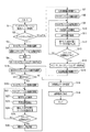
図1は、本発明を適用した実施形態に係るプロジェクションシステム1の構成を示す図である。プロジェクションシステム1は、スクリーンSC(投射面、操作面)の上方に設置されたプロジェクター10と、スクリーンSCの上部に設置された光出射装置60(光出射部)とを備える。
Hereinafter, embodiments of the present invention will be described with reference to the drawings.
FIG. 1 is a diagram showing a configuration of a projection system 1 according to an embodiment to which the present invention is applied. The projection system 1 includes a projector 10 installed above a screen SC (projection surface, operation surface) and a light emitting device 60 (light emitting unit) installed above the screen SC.

プロジェクター10はスクリーンSCの直上または斜め上方に設置され、斜め下方のスクリーンSCに向けて画像を投射する。また、本実施形態で例示するスクリーンSCは、壁面に固定され、或いは床面に立設された、平板または幕である。本発明はこの例に限定されず、壁面をスクリーンSCとして使用することも可能である。この場合、スクリーンSCとして使用される壁面の上部にプロジェクター10及び光出射装置60を取り付けるとよい。   The projector 10 is installed directly above or obliquely above the screen SC and projects an image toward the screen SC obliquely below. Further, the screen SC exemplified in the present embodiment is a flat plate or a curtain fixed to a wall surface or standing on a floor surface. The present invention is not limited to this example, and the wall surface can be used as the screen SC. In this case, the projector 10 and the light emitting device 60 may be attached to the upper part of the wall surface used as the screen SC.

プロジェクター10は、PC(パーソナルコンピューター)、ビデオ再生装置、DVD再生装置等の外部の画像供給装置に接続され、この画像供給装置から供給されるアナログ画像信号またはデジタル画像データに基づき、スクリーンSCに画像を投射する。また、プロジェクター10は、内蔵する記憶部110(図2)や外部接続される記憶媒体に記憶された画像データを読み出して、この画像データに基づきスクリーンSCに画像を表示する構成としてもよい。
光出射装置60は、固体光源からなる光源部61(図2)を有し、光源部61が発する光をスクリーンSCに沿って拡散させて出射(照射)する。光出射装置60の出射範囲を図1に角度θで示す。光出射装置60はスクリーンSCの上端より上に設置され、下向きに角度θの範囲に光を出射し、この光はスクリーンSCに沿う光の層を形成する。本実施形態では角度θはほぼ180度に達し、スクリーンSCのほぼ全体に、光の層が形成される。スクリーンSCの表面と光の層とは近接していることが好ましく、本実施形態では、スクリーンSCの表面と光の層との距離は概ね10mm〜1mmの範囲内である。
光出射装置60が出射する光は可視領域外の光であり、本実施形態では赤外光とする。
The projector 10 is connected to an external image supply device such as a PC (personal computer), a video reproduction device, a DVD reproduction device, and the like, and an image is displayed on the screen SC based on an analog image signal or digital image data supplied from the image supply device. Project. The projector 10 may be configured to read out image data stored in a built-in storage unit 110 (FIG. 2) or an externally connected storage medium and display an image on the screen SC based on the image data.
The light emitting device 60 has a light source unit 61 (FIG. 2) made of a solid light source, and diffuses (emits) light emitted from the light source unit 61 along the screen SC. The emission range of the light emitting device 60 is shown in FIG. The light emitting device 60 is installed above the upper end of the screen SC and emits light downward in the range of the angle θ, and this light forms a layer of light along the screen SC. In this embodiment, the angle θ reaches approximately 180 degrees, and a light layer is formed on almost the entire screen SC. The surface of the screen SC and the light layer are preferably close to each other. In this embodiment, the distance between the surface of the screen SC and the light layer is approximately in the range of 10 mm to 1 mm.
The light emitted from the light emitting device 60 is light outside the visible region, and is infrared light in this embodiment.

プロジェクションシステム1は、スクリーンSCに対する指示操作が行われた場合に、指示位置をプロジェクター10によって検出する。
指示操作に利用される指示体は、ペン型の指示体70を用いることができる。指示体70の先端部71は、押圧された場合に動作する操作スイッチ75(図2)を内蔵しているので、先端部71を壁やスクリーンSCに押しつける操作がされると操作スイッチ75がオンになる。指示体70は、ユーザーが棒状の軸部72を手に持って、先端部71をスクリーンSCに接触させるように操作され、先端部71をスクリーンSCに押しつける操作も行われる。先端部71には、光を発する送受信部74(図2)を備える。プロジェクター10は、指示体70が発する光に基づき、先端部71の位置を、指示位置として検出する。指示体70が発する光は可視領域外の光であり、本実施形態では赤外光とする。
The projection system 1 detects the indicated position by the projector 10 when an instruction operation is performed on the screen SC.
A pen-type indicator 70 can be used as the indicator used for the instruction operation. Since the distal end portion 71 of the indicator 70 incorporates an operation switch 75 (FIG. 2) that operates when pressed, the operation switch 75 is turned on when the distal end portion 71 is pressed against the wall or the screen SC. become. The indicator 70 is operated so that the user holds the rod-shaped shaft portion 72 in his / her hand and brings the tip portion 71 into contact with the screen SC, and an operation of pressing the tip portion 71 against the screen SC is also performed. The distal end portion 71 includes a transmission / reception unit 74 (FIG. 2) that emits light. The projector 10 detects the position of the distal end portion 71 as the indication position based on the light emitted from the indicator 70. The light emitted from the indicator 70 is light outside the visible region, and is infrared light in this embodiment.

また、ユーザーの手指である指示体80で位置指示操作を行う場合、ユーザーは指をスクリーンSCに接触させる。この場合、指示体80がスクリーンSCに接触した位置が検出される。
すなわち、指示体80の先端(例えば、指先)がスクリーンSCに接触するときに、光出射装置60が形成する光の層を遮る。このとき、光出射装置60が出射した光が指示体80に当たって反射し、反射光の一部は指示体80からプロジェクター10に向かって進む。プロジェクター10は、スクリーンSC側からの光、すなわち下方からの光を後述する位置検出部50により検出する機能を有するので、指示体80の反射光を検出できる。プロジェクター10は、指示体80で反射した反射光を検出することにより、指示体80によるスクリーンSCへの指示操作を検出する。また、プロジェクター10は指示体80により指示された指示位置を検出する。
光出射装置60が出射する光の層はスクリーンSCに近接しているので、指示体80において光が反射する位置は、スクリーンSCに最も近い先端、或いは指示位置と見なすことができる。このため、指示体80の反射光に基づき指示位置を特定できる。
Further, when a position indicating operation is performed with the indicator 80 that is a user's finger, the user brings the finger into contact with the screen SC. In this case, the position where the indicator 80 contacts the screen SC is detected.
That is, when the tip (for example, fingertip) of the indicator 80 contacts the screen SC, the light layer formed by the light emitting device 60 is blocked. At this time, the light emitted from the light emitting device 60 strikes and reflects the indicator 80, and part of the reflected light travels from the indicator 80 toward the projector 10. Since the projector 10 has a function of detecting light from the screen SC side, that is, light from below by the position detection unit 50 described later, the reflected light of the indicator 80 can be detected. The projector 10 detects an instruction operation on the screen SC by the indicator 80 by detecting the reflected light reflected by the indicator 80. Further, the projector 10 detects the indicated position indicated by the indicator 80.
Since the light layer emitted from the light emitting device 60 is close to the screen SC, the position where the light is reflected by the indicator 80 can be regarded as the tip closest to the screen SC or the indication position. For this reason, the indicated position can be specified based on the reflected light of the indicator 80.

プロジェクションシステム1は、インタラクティブホワイトボードシステムとして機能し、ユーザーが指示体70、80により行った指示操作を検出して、指示位置を投射画像に反映させる。
具体的には、プロジェクションシステム1は、指示位置に図形を描画したり文字や記号を配置したりする処理、指示位置の軌跡に沿って図形を描画する処理、描画した図形や配置した文字または記号を消去する処理等を行う。また、スクリーンSCに描画された図形、配置された文字または記号を画像データとして保存することもでき、外部の装置に出力することもできる。
さらに、指示位置を検出することによりポインティングデバイスとして動作し、スクリーンSCにプロジェクター10が画像を投射する画像投射領域における指示位置の座標を出力してもよい。また、この座標を用いてGUI(Graphical User Interface)操作を行ってもよい。
The projection system 1 functions as an interactive whiteboard system, detects an instruction operation performed by the user using the indicators 70 and 80, and reflects the indicated position on the projection image.
Specifically, the projection system 1 performs a process of drawing a graphic or placing a character or a symbol at a designated position, a process of drawing a graphic along the locus of the designated position, a drawn figure, a placed character or symbol The process etc. which erase | eliminate are performed. In addition, graphics drawn on the screen SC, arranged characters or symbols can be stored as image data, and can be output to an external device.
Further, it may operate as a pointing device by detecting the designated position, and output the coordinates of the designated position in the image projection area where the projector 10 projects an image on the screen SC. Further, a GUI (Graphical User Interface) operation may be performed using these coordinates.

図2は、プロジェクションシステム1を構成する各部の機能ブロック図である。
プロジェクター10は、外部の装置に接続されるインターフェイスとして、I/F(インターフェイス)部11及び画像I/F(インターフェイス)部12を備える。I/F部11及び画像I/F部12は有線接続用のコネクターを備え、上記コネクターに対応するインターフェイス回路を備えていてもよい。また、I/F部11及び画像I/F部12は、無線通信インターフェイスを備えていてもよい。有線接続用のコネクター及びインターフェイス回路としては有線LAN、IEEE1394、USB等に準拠したものが挙げられる。また、無線通信インターフェイスとしては無線LANやBluetooth(登録商標)等に準拠したものが挙げられる。画像I/F部12には、HDMI(登録商標)インターフェイス等の画像データ用のインターフェイスを用いることもできる。画像I/F部12は、音声データが入力されるインターフェイスを備えてもよい。
FIG. 2 is a functional block diagram of each part constituting the projection system 1.
The projector 10 includes an I / F (interface) unit 11 and an image I / F (interface) unit 12 as interfaces connected to external devices. The I / F unit 11 and the image I / F unit 12 may include a connector for wired connection, and may include an interface circuit corresponding to the connector. The I / F unit 11 and the image I / F unit 12 may include a wireless communication interface. Examples of the connector and interface circuit for wired connection include those based on wired LAN, IEEE 1394, USB, and the like. Examples of the wireless communication interface include those that comply with a wireless LAN, Bluetooth (registered trademark), or the like. The image I / F unit 12 may be an image data interface such as an HDMI (registered trademark) interface. The image I / F unit 12 may include an interface through which audio data is input.

I/F部11は、PC等の外部の装置との間で各種データを送受信するインターフェイスである。I/F部11は、画像の投射に関する制御データ、プロジェクター10の動作を設定する設定データ、プロジェクター10が検出した指示位置の座標データ等を入出力する。後述する制御部30は、I/F部11を介して外部の装置とデータを送受信する機能を有する。
画像I/F部12は、デジタル画像データが入力されるインターフェイスである。本実施形態のプロジェクター10は、画像I/F部12を介して入力されるデジタル画像データに基づき画像を投射する。なお、プロジェクター10は、アナログ画像信号に基づき画像を投射する機能を備えてもよく、この場合、画像I/F部12は、アナログ画像用のインターフェイスと、アナログ画像信号をデジタル画像データに変換するA/D変換回路とを備えてもよい。
The I / F unit 11 is an interface that transmits and receives various data to and from an external device such as a PC. The I / F unit 11 inputs and outputs control data related to image projection, setting data for setting the operation of the projector 10, coordinate data of the designated position detected by the projector 10, and the like. The control unit 30 described later has a function of transmitting / receiving data to / from an external device via the I / F unit 11.
The image I / F unit 12 is an interface through which digital image data is input. The projector 10 of the present embodiment projects an image based on digital image data input via the image I / F unit 12. The projector 10 may have a function of projecting an image based on the analog image signal. In this case, the image I / F unit 12 converts the analog image signal into digital image data and an analog image interface. And an A / D conversion circuit.

プロジェクター10は、光学的な画像の形成を行う投射部20を備える。投射部20は、光源部21、光変調装置22、および投射光学系23を有する。光源部21は、キセノンランプ、超高圧水銀ランプ、LED(Light Emitting Diode)、或いはレーザー光源等からなる光源を備える。また、光源部21は、光源が発した光を光変調装置22に導くリフレクターおよび補助リフレクターを備えていてもよい。さらに、投射光の光学特性を高めるためのレンズ群(図示略)、偏光板、或いは光源が発した光の光量を光変調装置22に至る経路上で低減させる調光素子等を備えていてもよい。
光変調装置22は、例えばRGBの三原色に対応した3枚の透過型液晶パネルを備え、この液晶パネルを透過する光を変調して画像光を生成する。光源部21からの光はRGBの3色の色光に分離され、各色光は対応する各液晶パネルに入射する。各液晶パネルを通過して変調された色光はクロスダイクロイックプリズム等の合成光学系によって合成され、投射光学系23に射出される。
The projector 10 includes a projection unit 20 that forms an optical image. The projection unit 20 includes a light source unit 21, a light modulation device 22, and a projection optical system 23. The light source unit 21 includes a light source including a xenon lamp, an ultra high pressure mercury lamp, an LED (Light Emitting Diode), a laser light source, or the like. The light source unit 21 may include a reflector and an auxiliary reflector that guide light emitted from the light source to the light modulation device 22. Further, a lens group (not shown) for enhancing the optical characteristics of the projection light, a polarizing plate, or a dimming element that reduces the amount of light emitted from the light source on the path to the light modulation device 22 may be provided. Good.
The light modulation device 22 includes, for example, three transmissive liquid crystal panels corresponding to the three primary colors of RGB, and generates image light by modulating light transmitted through the liquid crystal panel. The light from the light source unit 21 is separated into three color lights of RGB, and each color light enters each corresponding liquid crystal panel. The color light modulated by passing through each liquid crystal panel is combined by a combining optical system such as a cross dichroic prism and emitted to the projection optical system 23.

投射光学系23は、光変調装置22により変調された画像光をスクリーンSC方向へ導き、スクリーンSC上に結像させるレンズ群を備える。また、投射光学系23は、スクリーンSCの投射画像の拡大・縮小および焦点の調整を行うズーム機構、フォーカスの調整を行うフォーカス調整機構を備えていてもよい。プロジェクター10が短焦点型である場合、投射光学系23に、画像光をスクリーンSCに向けて反射する凹面鏡を備えていてもよい。   The projection optical system 23 includes a lens group that guides the image light modulated by the light modulation device 22 toward the screen SC and forms an image on the screen SC. Further, the projection optical system 23 may include a zoom mechanism for enlarging / reducing the projected image on the screen SC and adjusting the focus, and a focus adjusting mechanism for adjusting the focus. When the projector 10 is a short focus type, the projection optical system 23 may include a concave mirror that reflects image light toward the screen SC.

投射部20には、制御部30の制御に従って光源部21を点灯させる光源駆動部45、及び、制御部30の制御に従って光変調装置22を動作させる光変調装置駆動部46が接続される。光源駆動部45は、光源部21の点灯/消灯の切り替えを行い、光源部21の光量を調整する機能を有していてもよい。   The projection unit 20 is connected to a light source drive unit 45 that turns on the light source unit 21 according to the control of the control unit 30 and a light modulation device drive unit 46 that operates the light modulation device 22 according to the control of the control unit 30. The light source drive unit 45 may have a function of switching on / off the light source unit 21 and adjusting the light amount of the light source unit 21.

プロジェクター10は、投射部20が投射する画像を処理する画像処理系を備える。この画像処理系は、プロジェクター10を制御する制御部30、記憶部110、操作検出部17、画像処理部40、光源駆動部45、及び光変調装置駆動部46を含む。また、画像処理部40にはフレームメモリー44が接続され、制御部30には姿勢センサー47、出射装置駆動部48、及び位置検出部50が接続される。これらの各部を画像処理系に含めてもよい。   The projector 10 includes an image processing system that processes an image projected by the projection unit 20. The image processing system includes a control unit 30 that controls the projector 10, a storage unit 110, an operation detection unit 17, an image processing unit 40, a light source driving unit 45, and a light modulation device driving unit 46. In addition, a frame memory 44 is connected to the image processing unit 40, and an attitude sensor 47, an emission device driving unit 48, and a position detection unit 50 are connected to the control unit 30. These units may be included in the image processing system.

制御部30は、所定の制御プログラム111を実行することにより、プロジェクター10の各部を制御する。記憶部110は、制御部30が実行する制御プログラム111、および、制御部30が処理するデータを不揮発的に記憶する。記憶部110は、プロジェクター10の動作を設定するための画面の設定画面データ112、及び、設定画面データ112を利用して設定された内容を示す設定データ113を記憶する。   The control unit 30 controls each unit of the projector 10 by executing a predetermined control program 111. The storage unit 110 stores the control program 111 executed by the control unit 30 and the data processed by the control unit 30 in a nonvolatile manner. The storage unit 110 stores setting screen data 112 of a screen for setting the operation of the projector 10 and setting data 113 indicating the contents set using the setting screen data 112.

画像処理部40は、制御部30の制御に従って、画像I/F部12を介して入力される画像データを処理し、光変調装置駆動部46に画像信号を出力する。画像処理部40が実行する処理は、3D(立体)画像と2D(平面)画像の判別処理、解像度変換処理、フレームレート変換処理、歪み補正処理、デジタルズーム処理、色調補正処理、輝度補正処理等である。画像処理部40は、制御部30により指定された処理を実行し、必要に応じて、制御部30から入力されるパラメーターを使用して処理を行う。また、上記のうち複数の処理を組み合わせて実行することも勿論可能である。
画像処理部40はフレームメモリー44に接続されている。画像処理部40は、画像入力I/F12から入力される画像データをフレームメモリー44に展開して、展開した画像データに対し上記の各種処理を実行する。画像処理部40は、処理後の画像データをフレームメモリー44から読み出して、この画像データに対応するR、G、Bの画像信号を生成し、光変調装置駆動部46に出力する。
光変調装置駆動部46は、光変調装置22の液晶パネルに接続される。光変調装置駆動部46は、画像処理部40から入力される画像信号に基づいて液晶パネルを駆動し、各液晶パネルに画像を描画する。
The image processing unit 40 processes the image data input via the image I / F unit 12 under the control of the control unit 30, and outputs an image signal to the light modulation device driving unit 46. The processing executed by the image processing unit 40 includes 3D (stereoscopic) image and 2D (planar) image discrimination processing, resolution conversion processing, frame rate conversion processing, distortion correction processing, digital zoom processing, color tone correction processing, luminance correction processing, and the like. is there. The image processing unit 40 executes processing designated by the control unit 30 and performs processing using parameters input from the control unit 30 as necessary. Of course, it is also possible to execute a combination of a plurality of processes.
The image processing unit 40 is connected to the frame memory 44. The image processing unit 40 expands the image data input from the image input I / F unit 12 in the frame memory 44, and executes the various processes described above on the expanded image data. The image processing unit 40 reads out the processed image data from the frame memory 44, generates R, G, B image signals corresponding to the image data, and outputs them to the light modulation device driving unit 46.
The light modulation device driving unit 46 is connected to the liquid crystal panel of the light modulation device 22. The light modulator driving unit 46 drives the liquid crystal panel based on the image signal input from the image processing unit 40 and draws an image on each liquid crystal panel.

操作検出部17は、入力デバイスとして機能するリモコン受光部18および操作パネル19に接続され、リモコン受光部18及び操作パネル19を介した操作を検出する。
リモコン受光部18は、プロジェクター10のユーザーが使用するリモコン(図示略)がボタン操作に対応して送信した赤外線信号を受光する。リモコン受光部18は、上記リモコンから受光した赤外線信号をデコードして、上記リモコンにおける操作内容を示す操作データを生成し、制御部30に出力する。
操作パネル19は、プロジェクター10の外装筐体に設けられ、各種スイッチおよびインジケーターランプを有する。操作検出部17は、制御部30の制御に従い、プロジェクター10の動作状態や設定状態に応じて操作パネル19のインジケーターランプを適宜点灯及び消灯させる。この操作パネル19のスイッチが操作されると、操作されたスイッチに対応する操作データが操作検出部17から制御部30に出力される。
The operation detection unit 17 is connected to the remote control light receiving unit 18 and the operation panel 19 that function as an input device, and detects an operation through the remote control light reception unit 18 and the operation panel 19.
Remote control receiver 18, a remote controller (not shown) that the user of the projector 10 is used to receive optical infrared signals transmitted in response to the button operation. The remote control light receiving unit 18 decodes the infrared signal received from the remote control, generates operation data indicating the operation content of the remote control, and outputs the operation data to the control unit 30.
The operation panel 19 is provided in the exterior housing of the projector 10 and has various switches and indicator lamps. The operation detection unit 17 appropriately turns on and off the indicator lamp of the operation panel 19 according to the operation state and setting state of the projector 10 according to the control of the control unit 30. When the switch of the operation panel 19 is operated, operation data corresponding to the operated switch is output from the operation detection unit 17 to the control unit 30.

出射装置駆動部48は、接続部49を介して光出射装置60に接続される。接続部49は、例えば複数のピンを有するコネクターであり、接続部49には光出射装置60がケーブル60aを介して接続される。出射装置駆動部48は、制御部30の制御に従ってパルス信号を生成し、接続部49を介して光出射装置60に出力する。また、出射装置駆動部48は接続部49を介して光出射装置60に電源を供給する。   The emission device driving unit 48 is connected to the light emission device 60 via the connection unit 49. The connection portion 49 is a connector having a plurality of pins, for example, and the light emitting device 60 is connected to the connection portion 49 via a cable 60a. The emission device driving unit 48 generates a pulse signal according to the control of the control unit 30 and outputs the pulse signal to the light emission device 60 via the connection unit 49. Further, the emission device driving unit 48 supplies power to the light emission device 60 through the connection unit 49.

光出射装置60は、図1に示すように略箱形のケースに、光源部61、及び光学部品を収容して構成される。本実施形態の光出射装置60は、光源部61に、赤外光を発する固体光源62を備える。固体光源62が発する赤外光は、平行化レンズ及びパウエルレンズによって拡散され、スクリーンSCに沿った面を形成する。また、光源部61が複数の固体光源を備え、これら複数の固体光源が発する光をそれぞれ拡散させることによって、スクリーンSCの画像投射範囲を覆うように光の層を形成してもよい。また、光出射装置60は、光源部61が発する光の層とスクリーンSCとの間の距離や角度を調整する調整機構を備えていてもよい。   As shown in FIG. 1, the light emitting device 60 is configured by housing a light source unit 61 and optical components in a substantially box-shaped case. The light emitting device 60 of this embodiment includes a solid light source 62 that emits infrared light in a light source unit 61. The infrared light emitted from the solid light source 62 is diffused by the collimating lens and the Powell lens to form a surface along the screen SC. The light source unit 61 may include a plurality of solid light sources, and a light layer may be formed so as to cover the image projection range of the screen SC by diffusing light emitted from the plurality of solid light sources. The light emitting device 60 may include an adjustment mechanism that adjusts the distance and angle between the light layer emitted from the light source unit 61 and the screen SC.

光出射装置60は、出射装置駆動部48から供給されるパルス信号および電源により、光源部61を点灯させる。光源部61が点灯及び消灯するタイミングは、出射装置駆動部48が制御する。制御部30は、出射装置駆動部48を制御して、後述する撮像部51が撮影を行うタイミングに同期して光源部61を点灯させる。   The light emitting device 60 turns on the light source unit 61 with the pulse signal and power supplied from the emitting device driving unit 48. The emission device driving unit 48 controls the timing at which the light source unit 61 is turned on and off. The control unit 30 controls the emission device driving unit 48 to turn on the light source unit 61 in synchronization with the timing when the imaging unit 51 described later performs imaging.

位置検出部50(検出部)は、指示体70、80によるスクリーンSCへの操作を検出する。位置検出部50は、撮像部51、送信部52、撮影制御部53、指示体検出部54、および座標算出部55の各部を備えて構成される。
撮像部51は、撮像光学系、撮像素子、インターフェイス回路等を有し、投射光学系23の投射方向を撮影する。撮像部51の撮像光学系は、投射光学系23と略同じ方向を向いて配置され、投射光学系23がスクリーンSC上に画像を投射する範囲をカバーする画角を有する。また、撮像素子は、赤外領域及び可視光領域の光を受光するCCDやCMOSが挙げられる。撮像部51は、撮像素子に入射する光の一部を遮るフィルターを備えてもよく、例えば、赤外光を受光させる場合に、主に赤外領域の光を透過するフィルターを撮像素子の前に配置させてもよい。また、撮像部51のインターフェイス回路は、撮像素子の検出値を読み出して出力する。
The position detection unit 50 (detection unit) detects an operation on the screen SC by the indicators 70 and 80. The position detection unit 50 includes an imaging unit 51, a transmission unit 52, an imaging control unit 53, a pointer detection unit 54, and a coordinate calculation unit 55.
The imaging unit 51 includes an imaging optical system, an imaging element, an interface circuit, and the like, and images the projection direction of the projection optical system 23. The imaging optical system of the imaging unit 51 is arranged so as to face substantially the same direction as the projection optical system 23, and has an angle of view that covers a range in which the projection optical system 23 projects an image on the screen SC. Examples of the imaging device include a CCD and a CMOS that receive light in the infrared region and the visible light region. The imaging unit 51 may include a filter that blocks a part of the light incident on the imaging element. For example, when receiving infrared light, a filter that mainly transmits infrared light is provided in front of the imaging element. May be arranged. Further, the interface circuit of the imaging unit 51 reads and outputs the detection value of the imaging element.

撮影制御部53は、撮像部51により撮影を実行させて撮影画像データを生成する。撮像素子が可視光による撮影を行うと、スクリーンSC上に投射された画像が撮影される。例えば、後述するオートキャリブレーションの画像は、可視光で撮影される。また、撮影制御部53は、撮像部51により赤外光を撮影させることができ、この場合の撮影画像には指示体70が発する赤外光(赤外線信号)や、指示体80に反射した反射光が写る。   The imaging control unit 53 causes the imaging unit 51 to perform imaging and generates captured image data. When the imaging device performs imaging with visible light, an image projected on the screen SC is captured. For example, an auto-calibration image to be described later is taken with visible light. In addition, the imaging control unit 53 can cause the imaging unit 51 to capture infrared light. In this case, the captured image includes infrared light (infrared signal) emitted from the indicator 70 or reflection reflected by the indicator 80. Light is reflected.

指示体検出部54は、撮影制御部53が撮影した撮影画像データに基づいて指示体70、80の指示位置を検出する。指示体検出部54は、撮影制御部53が撮像部51によって赤外光の撮影を実行させた場合の撮影画像データから、指示体70が発した赤外光の像、及び/又は、指示体80に反射した反射光の像を検出する。さらに、指示体検出部54は、検出した像を、指示体70が発した光の像であるか、指示体80の反射光の像であるか判別してもよい。
座標算出部55は、指示体検出部54が検出した像の位置に基づき、撮影画像データにおける指示体70、80の指示位置の座標を算出して、制御部30に出力する。座標算出部55は、また、投射部20が投射した投射画像における指示体70、80の指示位置の座標を算出して、制御部30に出力してもよい。さらに、座標算出部55は、画像処理部40がフレームメモリー44に描画した画像データにおける指示体70、80の指示位置の座標や、画像I/F部12の入力画像データにおける指示体70、80の指示位置の座標を、算出してもよい。
The indicator detection unit 54 detects the indication positions of the indicators 70 and 80 based on the captured image data captured by the imaging control unit 53. The indicator detection unit 54 includes an infrared light image and / or indicator emitted by the indicator 70 from the captured image data when the imaging control unit 53 causes the imaging unit 51 to perform infrared imaging. An image of the reflected light reflected by 80 is detected. Further, the indicator detection unit 54 may determine whether the detected image is an image of light emitted from the indicator 70 or an image of reflected light from the indicator 80.
The coordinate calculation unit 55 calculates the coordinates of the pointing positions of the pointers 70 and 80 in the captured image data based on the position of the image detected by the pointer detection unit 54 and outputs the calculated coordinates to the control unit 30. The coordinate calculation unit 55 may also calculate the coordinates of the indication positions of the indicators 70 and 80 in the projection image projected by the projection unit 20 and output them to the control unit 30. Further, the coordinate calculation unit 55 is configured to display the coordinates of the pointing positions of the indicators 70 and 80 in the image data drawn by the image processing unit 40 in the frame memory 44 and the indicators 70 and 80 in the input image data of the image I / F unit 12. The coordinates of the designated position may be calculated.

送信部52は、指示体検出部54の制御に従って、指示体70に対して赤外線信号を送信する。送信部52は、赤外LED等の光源を有し、この光源を指示体検出部54の制御に従って点灯及び消灯させる。   The transmission unit 52 transmits an infrared signal to the indicator 70 according to the control of the indicator detection unit 54. The transmission unit 52 has a light source such as an infrared LED, and turns on and off the light source according to the control of the indicator detection unit 54.

また、指示体70は、制御部73、送受信部74、操作スイッチ75、及び電源部76を備え、これらの各部は軸部72(図1)に収容される。制御部73は、送受信部74及び操作スイッチ75に接続され、操作スイッチ75のオン/オフ状態を検出する。送受信部74は、赤外LED等の光源と、赤外光を受光する受光素子とを備え、制御部73の制御に従って光源を点灯及び消灯させるとともに、受光素子の受光状態を示す信号を制御部73に出力する。
電源部76は、電源として乾電池または二次電池を有し、制御部73、送受信部74、及び操作スイッチ75の各部に電力を供給する。
指示体70は、電源部76からの電源供給をオン/オフする電源スイッチを備えていてもよい。
Moreover, the indicator 70 is provided with the control part 73, the transmission / reception part 74, the operation switch 75, and the power supply part 76, and these each part is accommodated in the axial part 72 (FIG. 1). The control unit 73 is connected to the transmission / reception unit 74 and the operation switch 75 and detects the on / off state of the operation switch 75. The transmission / reception unit 74 includes a light source such as an infrared LED and a light receiving element that receives infrared light. To 73.
The power supply unit 76 includes a dry battery or a secondary battery as a power supply, and supplies power to the control unit 73, the transmission / reception unit 74, and the operation switch 75.
The indicator 70 may include a power switch that turns on / off the power supply from the power supply unit 76.

ここで、位置検出部50と指示体70との相互の通信により、撮像部51の撮影画像データから指示体70を特定する方法について説明する。
制御部30は、指示体70による位置指示操作を検出する場合に、指示体検出部54を制御して、送信部52から同期用の信号を送信させる。すなわち、指示体検出部54は、制御部30の制御に従って、送信部52の光源を所定の周期で点灯させる。送信部52が周期的に発する赤外光が、位置検出部50と指示体70とを同期させる同期信号として機能する。
一方、制御部73は、電源部76から電源の供給が開始され、所定の初期化動作を行った後、プロジェクター10の送信部52が発する赤外光を、送受信部74により受光する。送信部52が周期的に発する赤外光を送受信部74により受光すると、制御部73は、この赤外光のタイミングに同期させて、予め設定された点灯パターンで、送受信部74の光源を点灯(発光)させる。この点灯のパターンは、光源の点灯と消灯をデータのオンとオフに対応させて、指示体70に固有のデータを表す。制御部73は設定されたパターンの点灯時間及び消灯時間に従って光源を点灯及び消灯させる。制御部73は、電源部76から電源が供給されている間、上記のパターンを繰り返し実行する。
つまり、位置検出部50は指示体70に対し、同期用の赤外線信号を周期的に送信し、指示体70は、位置検出部50が送信する赤外線信号に同期して、予め設定された赤外線信号を送信する。
Here, a method of specifying the indicator 70 from the captured image data of the imaging unit 51 by mutual communication between the position detection unit 50 and the indicator 70 will be described.
When detecting the position pointing operation by the pointer 70, the control unit 30 controls the pointer detection unit 54 to transmit a synchronization signal from the transmission unit 52. That is, the indicator detection unit 54 turns on the light source of the transmission unit 52 at a predetermined period in accordance with the control of the control unit 30. The infrared light periodically emitted from the transmission unit 52 functions as a synchronization signal that synchronizes the position detection unit 50 and the indicator 70.
On the other hand, after the supply of power from the power supply unit 76 is started and a predetermined initialization operation is performed, the control unit 73 receives infrared light emitted from the transmission unit 52 of the projector 10 by the transmission / reception unit 74. When the transmission / reception unit 74 receives infrared light periodically generated by the transmission unit 52, the control unit 73 lights the light source of the transmission / reception unit 74 in a preset lighting pattern in synchronization with the timing of the infrared light. (Light emission). This lighting pattern represents data specific to the indicator 70 by turning on and off the light source corresponding to ON and OFF of the data. The control unit 73 turns on and off the light source in accordance with the set pattern turn-on time and turn-off time. The control unit 73 repeatedly executes the above pattern while power is supplied from the power supply unit 76.
That is, the position detection unit 50 periodically transmits an infrared signal for synchronization to the indicator 70, and the indicator 70 synchronizes with the infrared signal transmitted by the position detection unit 50 to set the infrared signal set in advance. Send.

位置検出部50の撮影制御部53は、撮像部51による撮影タイミングを、指示体70が点灯するタイミングに合わせる制御を行う。この撮影タイミングは、指示体検出部54が送信部52を点灯させるタイミングに基づいて決定される。指示体検出部54は、撮像部51の撮影画像データに指示体70の光の像が写っているか否かにより、指示体70が点灯するパターンを特定できる。
指示体70が点灯するパターンは、指示体70の個体毎に固有のパターン、または、複数の指示体70に共通のパターンと個体毎に固有のパターンとを含むものとすることができる。この場合、指示体検出部54は、撮影画像データに複数の指示体70が発する赤外光の像が含まれる場合に、各々の像を、異なる指示体70の像として区別できる。
The shooting control unit 53 of the position detection unit 50 performs control to match the shooting timing of the imaging unit 51 with the timing when the indicator 70 is turned on. This shooting timing is determined based on the timing when the indicator detection unit 54 turns on the transmission unit 52. The indicator detection unit 54 can specify a pattern in which the indicator 70 is turned on depending on whether or not the image of the light of the indicator 70 is captured in the captured image data of the imaging unit 51.
The pattern in which the indicator 70 is lit may include a pattern unique to each individual indicator 70, or a pattern common to a plurality of indicators 70 and a pattern unique to each individual. In this case, the indicator detection unit 54 can distinguish each image as an image of a different indicator 70 when the captured image data includes images of infrared light emitted from the plurality of indicators 70.

また、制御部30は、出射装置駆動部48を制御して、光源部61の点灯のタイミングを撮像部51の撮影のタイミングに同期させる。光源部61が、撮像部51の撮影タイミングに合わせてパルス点灯すると、指示体80がスクリーンSC上を指し示す場合には、撮像部51の撮影画像に指示体80の反射光が写る。光源部61を、指示体70の点灯のタイミングと区別できるパターンで点灯させれば、指示体検出部54は、撮影画像データに写る像が指示体70であるか指示体80であるかを判定できる。光源部61の点灯のタイミングについては図8を参照して後述する。   In addition, the control unit 30 controls the emission device driving unit 48 to synchronize the lighting timing of the light source unit 61 with the imaging timing of the imaging unit 51. When the light source unit 61 turns on the pulse in synchronization with the imaging timing of the imaging unit 51, the reflected light of the indicator 80 appears in the captured image of the imaging unit 51 when the indicator 80 points on the screen SC. When the light source unit 61 is turned on in a pattern that can be distinguished from the lighting timing of the indicator 70, the indicator detection unit 54 determines whether the image shown in the captured image data is the indicator 70 or the indicator 80. it can. The lighting timing of the light source unit 61 will be described later with reference to FIG.

さらに、指示体70が備える制御部73は、操作スイッチ75の操作状態に応じて、送受信部74を点灯させるパターンを切り替える。このため、指示体検出部54は、複数の撮影画像データに基づいて、指示体70の操作状態、すなわち先端部71がスクリーンSCに押しつけられているか否かを判定できる。   Further, the control unit 73 included in the indicator 70 switches the pattern for lighting the transmission / reception unit 74 according to the operation state of the operation switch 75. For this reason, the indicator detection unit 54 can determine the operating state of the indicator 70, that is, whether or not the distal end portion 71 is pressed against the screen SC, based on a plurality of captured image data.

姿勢センサー47は、加速度センサーやジャイロセンサー等により構成され、制御部30に対して検出値を出力する。姿勢センサー47はプロジェクター10の本体に対して、プロジェクター10の設置方向を識別可能なように固定される。
プロジェクター10は、図1に示したように壁面や天井面から吊り下げる吊り下げ設置の他に、スクリーンSCの下方から投射を行う設置状態、机の天面などの水平面をスクリーンSCとして使用する設置状態等で使用できる。プロジェクター10の設置状態によっては光出射装置60の使用に適さないことがある。例えば、下方からスクリーンSCに投射を行う場合、ユーザーの体が光出射装置60の出射光を遮ってしまうことがあり、不適である。姿勢センサー47は、プロジェクター10の設置状態として想定される複数の設置状態を識別できるように、プロジェクター10の本体に設けられる。姿勢センサー47は、例えば、2軸のジャイロセンサー、1軸のジャイロセンサー、加速度センサー等を用いて構成される。制御部30は、姿勢センサー47の出力値に基づきプロジェクター10の設置状態を自動的に判定できる。制御部30が、光出射装置60の使用に不適な設置状態と判定した場合には、例えば、出射装置駆動部48が電源電圧やパルス信号の出力を停止する。
The attitude sensor 47 is configured by an acceleration sensor, a gyro sensor, or the like, and outputs a detection value to the control unit 30. The attitude sensor 47 is fixed to the main body of the projector 10 so that the installation direction of the projector 10 can be identified.
As shown in FIG. 1, the projector 10 is installed in a suspended state in which it is suspended from a wall surface or a ceiling surface, in an installation state in which projection is performed from below the screen SC, or in a horizontal plane such as the top surface of a desk. Can be used in situations. Depending on the installation state of the projector 10, the light emitting device 60 may not be suitable for use. For example, when the projection is performed on the screen SC from below, the user's body may block the emitted light of the light emitting device 60, which is inappropriate. The attitude sensor 47 is provided in the main body of the projector 10 so that a plurality of installation states assumed as the installation state of the projector 10 can be identified. The attitude sensor 47 is configured using, for example, a biaxial gyro sensor, a monoaxial gyro sensor, an acceleration sensor, or the like. The control unit 30 can automatically determine the installation state of the projector 10 based on the output value of the attitude sensor 47. When the control unit 30 determines that the installation state is inappropriate for the use of the light emitting device 60, for example, the emission device driving unit 48 stops outputting the power supply voltage and the pulse signal.

制御部30は、記憶部110に記憶された制御プログラム111を読み出して実行することにより、投射制御部31、検出制御部32、出射制御部33、及びキャリブレーション制御部39の機能を実現し、プロジェクター10の各部を制御する。
投射制御部31は、操作検出部17から入力される操作データに基づいて、ユーザーが行った操作の内容を取得する。投射制御部31は、ユーザーが行った操作に応じて画像処理部40、光源駆動部45、及び光変調装置駆動部46を制御して、スクリーンSCに画像を投射させる。投射制御部31は、画像処理部40を制御して、上述した3D(立体)画像と2D(平面)画像の判別処理、解像度変換処理、フレームレート変換処理、歪み補正処理、デジタルズーム処理、色調補正処理、輝度補正処理等を実行させる。また、投射制御部31は、画像処理部40の処理に合わせて光源駆動部45を制御し、光源部21の光量を制御する。
The control unit 30 reads out and executes the control program 111 stored in the storage unit 110, thereby realizing the functions of the projection control unit 31, the detection control unit 32, the emission control unit 33, and the calibration control unit 39, Each part of the projector 10 is controlled.
The projection control unit 31 acquires the content of the operation performed by the user based on the operation data input from the operation detection unit 17. The projection control unit 31 controls the image processing unit 40, the light source driving unit 45, and the light modulation device driving unit 46 according to the operation performed by the user to project an image on the screen SC. The projection control unit 31 controls the image processing unit 40 to determine the above-described 3D (stereoscopic) image and 2D (planar) image, resolution conversion processing, frame rate conversion processing, distortion correction processing, digital zoom processing, and tone correction. Processing, brightness correction processing, and the like are executed. Further, the projection control unit 31 controls the light source driving unit 45 in accordance with the processing of the image processing unit 40 and controls the light amount of the light source unit 21.

検出制御部32は、位置検出部50を制御して、指示体70、80の操作位置の検出を実行させ、操作位置の座標を取得する。また、検出制御部32は、操作位置の座標とともに、指示体70の操作位置であるか指示体80の操作位置であるかを識別するデータ、及び、操作スイッチ75の操作状態を示すデータを取得する。検出制御部32は、取得した座標及びデータに基づいて、予め設定された処理を実行する。例えば、画像処理部40によって、取得した座標に基づいて図形を描画させ、描画した図形を画像I/F部12に入力される入力画像に重畳して投射させる処理を行う。また、検出制御部32は、取得した座標をI/F部11に接続されたPC等の外部の装置に出力してもよい。この場合、検出制御部32は、取得した座標を、I/F部11に接続された外部の装置のオペレーティングシステムにおいて、座標入力デバイスの入力として認識されるデータフォーマットに変換して出力してもよい。例えば、I/F部11にWindows(登録商標)オペレーティングシステムで動作するPCが接続された場合、オペレーティングシステムにおいてHID(Human Interface Device)の入力データとして処理されるデータを出力する。また、検出制御部32は、座標のデータとともに、指示体70の操作位置であるか指示体80の操作位置であるかを識別するデータ、及び、操作スイッチ75の操作状態を示すデータを出力してもよい。   The detection control unit 32 controls the position detection unit 50 to detect the operation positions of the indicators 70 and 80 and acquires the coordinates of the operation positions. Further, the detection control unit 32 obtains data for identifying whether it is the operation position of the indicator 70 or the operation position of the indicator 80 and data indicating the operation state of the operation switch 75 together with the coordinates of the operation position. To do. The detection control unit 32 executes a preset process based on the acquired coordinates and data. For example, the image processing unit 40 performs a process of drawing a figure based on the acquired coordinates and superimposing the drawn figure on an input image input to the image I / F unit 12 and projecting it. The detection control unit 32 may output the acquired coordinates to an external device such as a PC connected to the I / F unit 11. In this case, the detection control unit 32 may convert the acquired coordinates into a data format recognized as an input of the coordinate input device in the operating system of the external device connected to the I / F unit 11 and output the converted data. Good. For example, when a PC operating on a Windows (registered trademark) operating system is connected to the I / F unit 11, data processed as input data of HID (Human Interface Device) in the operating system is output. In addition to the coordinate data, the detection control unit 32 outputs data for identifying whether the position is the operation position of the indicator 70 or the operation position of the indicator 80 and data indicating the operation state of the operation switch 75. May be.

また、検出制御部32は、指示体80を使用した位置検出を制御する。具体的には、検出制御部32は、光出射装置60の接続の有無に基づき、光出射装置60を使用できるか否かを判定する。検出制御部32は、光出射装置60を使用できない場合に、光出射装置60の使用を不可とする設定を行う。ここで、検出制御部32は、光出射装置60を使用できないことを報知してもよい。   Further, the detection control unit 32 controls position detection using the indicator 80. Specifically, the detection control unit 32 determines whether or not the light emitting device 60 can be used based on whether or not the light emitting device 60 is connected. When the light emitting device 60 cannot be used, the detection control unit 32 performs setting so that the light emitting device 60 cannot be used. Here, the detection control unit 32 may notify that the light emitting device 60 cannot be used.

出射制御部33は、出射装置駆動部48を制御して、接続部49に接続された光出射装置60に対する電源及びパルス信号の出力を実行または停止させる。出射制御部33は、検出制御部32の制御により、光出射装置60を使用できない又は使用しない場合に、出射装置駆動部48の電源及びパルス信号の出力を停止させる。また、光出射装置60を使用する場合、出射制御部33は出射装置駆動部48の電源及びパルス信号を出力させる。   The emission control unit 33 controls the emission device driving unit 48 to execute or stop the output of the power source and the pulse signal to the light emission device 60 connected to the connection unit 49. The emission control unit 33 controls the detection control unit 32 to stop the power supply of the emission device driving unit 48 and the output of the pulse signal when the light emission device 60 cannot be used or is not used. When the light emitting device 60 is used, the emission control unit 33 outputs the power supply and pulse signal of the emission device driving unit 48.

キャリブレーション制御部39は、指示体70および指示体80の指示位置を検出して、画像I/F部12の入力画像における座標に変換するためのキャリブレーションを実行する。
図3に示すフローチャート及び各図を参照しながら、制御部30の処理手順、特にキャリブレーション制御部39の処理手順を説明する。
The calibration control unit 39 detects the indication positions of the indicator 70 and the indicator 80 and executes calibration for conversion into coordinates in the input image of the image I / F unit 12.
The processing procedure of the control unit 30, particularly the processing procedure of the calibration control unit 39, will be described with reference to the flowchart shown in FIG.

キャリブレーションは、プロジェクター10を最初に使用する際に初期設定の1つとして実行される。キャリブレーションは、フレームメモリー44に描画され投射部20が投射する画像における位置と、撮像部51が撮影する撮影画像データ上の位置とを対応付ける処理である。位置検出部50が撮影画像データから検出する指示体70、80の指示位置は、撮影画像データにおける位置であり、例えば撮影画像に設定される座標系における座標で示される。ユーザーはスクリーンSCに投射された投射画像を意識して指示体70、80で指示を行う。従って、プロジェクター10は、スクリーンSC上の投射画像に対する指示位置を特定する必要がある。キャリブレーションによって、撮影画像データで検出された位置の座標を投射画像データ上の座標に変換できる。この対応づけを行うデータをキャリブレーションデータとする。キャリブレーションデータは、撮影制御部53が出力する撮影画像データ上の座標と投射画像上の座標とを対応付けるデータである。具体的には、撮影画像データ上の座標と投射画像上の座標とを1対1で対応付けるテーブルであってもよいし、撮影画像データ上の座標を投射画像上の座標に変換する関数であってもよい。   The calibration is executed as one of initial settings when the projector 10 is used for the first time. Calibration is a process of associating a position in an image drawn in the frame memory 44 and projected by the projection unit 20 with a position on the captured image data captured by the imaging unit 51. The indication positions of the indicators 70 and 80 detected by the position detection unit 50 from the photographed image data are positions in the photographed image data, and are indicated by coordinates in a coordinate system set for the photographed image, for example. The user gives instructions using the indicators 70 and 80 in consideration of the projection image projected on the screen SC. Therefore, the projector 10 needs to specify the designated position for the projection image on the screen SC. By calibration, the coordinates of the position detected in the captured image data can be converted into the coordinates on the projection image data. Data for performing this association is referred to as calibration data. The calibration data is data that associates the coordinates on the photographed image data output from the photographing control unit 53 with the coordinates on the projection image. Specifically, it may be a table in which the coordinates on the captured image data and the coordinates on the projected image are associated one-to-one, or a function that converts the coordinates on the captured image data into the coordinates on the projected image. May be.

キャリブレーション制御部39は、指示体の種類に応じてキャリブレーションを実行する。すなわち、指示体70の指示位置の検出に関するキャリブレーションと、指示体80の指示位置の検出に関するキャリブレーションとの2つを実行する。
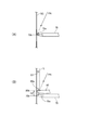
図4は、指示体70、80の指示位置を検出する様子を示す説明図であり、(A)は指示体70の指示位置を検出する様子を示し、(B)は指示体80の指示位置を検出する様子を示す。
図4(A)には撮像部51がスクリーンSCを撮影する撮影方向を符号PAで示す。指示体70の位置検出を行う場合、送受信部74は、指示体70の先端の発光位置70aから赤外光を出射する。発光位置70aは、指示体70がスクリーンSCに接する接触点70bに非常に近い。このため、撮影方向PAから撮影した撮影画像データから指示体70が発する光の像を検出する場合、この像の位置を、接触点70bの位置とみなすことができる。
The calibration control unit 39 executes calibration according to the type of the indicator. That is, two calibrations are executed: calibration relating to detection of the indicated position of the indicator 70 and calibration relating to detection of the indicated position of the indicator 80.
4A and 4B are explanatory diagrams showing how the pointing positions of the pointers 70 and 80 are detected. FIG. 4A shows how the pointing position of the pointer 70 is detected. FIG. 4B shows the pointing position of the pointer 80. A state of detecting is shown.
In FIG. 4A, the imaging direction in which the imaging unit 51 captures the screen SC is indicated by symbol PA. When detecting the position of the indicator 70, the transmission / reception unit 74 emits infrared light from the light emission position 70 a at the tip of the indicator 70. The light emission position 70a is very close to the contact point 70b where the indicator 70 contacts the screen SC. For this reason, when detecting an image of light emitted from the indicator 70 from the captured image data captured from the imaging direction PA, the position of this image can be regarded as the position of the contact point 70b.

これに対し、図4(B)に示すように指示体80の指示位置を検出する場合には、検出光Lが指示体80で反射した反射光を検出する。すなわち、撮影方向PAから撮影される撮影画像データから、検出光Lの反射光の像が検出される。検出光Lの出射方向はスクリーンSCとほぼ平行であり、検出光LはスクリーンSCから所定の距離(以下、距離G1とする)だけ離れている。距離G1はスクリーンSCに対する光出射装置60の取付位置により変化するが、構造上、距離G1をゼロにすることは困難である。このため、撮影方向PAから撮影した撮影画像データには、指示体80の先端において、スクリーンSCから距離G1だけ離れた反射位置80aで反射した反射光の像が写る。
図4(B)に示すように、反射位置80aは、撮影方向PAに対して斜めの方向に離れている。このため、撮影画像データに写る反射光の像の位置は、撮影方向PAにおいて、より離れた位置を指示体70で指示した場合の像と同じ位置になる。つまり、指示体80が接触点80bでスクリーンSCに接触した場合の反射光と、指示体70が接触点70bでスクリーンSCに接触した場合の光とが、撮像部51の撮影画像データでは同じ位置に写る。このため、指示体80が指し示す接触点80bは、撮影方向PAにおいて撮像部51から離れた接触点70bとして検出され、距離G2のずれを生じる。
On the other hand, when the indication position of the indicator 80 is detected as shown in FIG. 4B, the reflected light reflected by the indicator 80 is detected. That is, the reflected light image of the detection light L is detected from the captured image data captured from the capturing direction PA. The emission direction of the detection light L is substantially parallel to the screen SC, and the detection light L is separated from the screen SC by a predetermined distance (hereinafter referred to as distance G1). Although the distance G1 varies depending on the mounting position of the light emitting device 60 with respect to the screen SC, it is difficult to make the distance G1 zero due to the structure. For this reason, in the captured image data captured from the capturing direction PA, an image of the reflected light reflected at the reflection position 80a separated from the screen SC by the distance G1 is captured at the tip of the indicator 80.
As shown in FIG. 4B, the reflection position 80a is away from the imaging direction PA in an oblique direction. For this reason, the position of the image of the reflected light reflected in the captured image data is the same position as the image in the case where the indicator 70 indicates a more distant position in the capturing direction PA. That is, the reflected light when the indicator 80 contacts the screen SC at the contact point 80b and the light when the indicator 70 contacts the screen SC at the contact point 70b are the same position in the captured image data of the imaging unit 51. It is reflected in. For this reason, the contact point 80b pointed to by the indicator 80 is detected as the contact point 70b away from the imaging unit 51 in the shooting direction PA, and a shift of the distance G2 occurs.

距離G2のずれは、撮像部51が、スクリーンSCから離れた位置から斜めに撮影を行うことに起因する。例えば、図4(A)、(B)に示す撮影方向PAと指示体70、80との位置関係は、上下方向に限らず、水平方向においても同様に発生する。本実施形態では、図1に示したようにスクリーンSCの上方に位置するプロジェクター10の本体に設けられた1つの撮像部51が、スクリーンSCを俯瞰して撮影するため、上下及び水平の両方向において距離G2のずれが発生する。   The shift in the distance G2 is caused by the imaging unit 51 taking an image obliquely from a position away from the screen SC. For example, the positional relationship between the shooting direction PA and the indicators 70 and 80 shown in FIGS. 4A and 4B occurs not only in the vertical direction but also in the horizontal direction. In the present embodiment, as shown in FIG. 1, since one imaging unit 51 provided in the main body of the projector 10 located above the screen SC shoots the screen SC in an overhead view, both in the vertical and horizontal directions. A shift of the distance G2 occurs.

そこで、プロジェクター10は、指示体80の指示位置を検出する場合に、指示体70の指示位置を検出する場合と同様に指示位置を検出した後に、検出した位置を補正する。
具体的には、キャリブレーション制御部39が、指示体70の指示位置の検出に関するキャリブレーションを行って、キャリブレーションデータを生成する。このキャリブレーションデータを使用すれば、例えば図4(A)に示すように、発光位置70aがスクリーンSCとの接触点70bに近い場合に、高精度で指示位置を検出できる。
Therefore, when detecting the indication position of the indicator 80, the projector 10 corrects the detected position after detecting the indication position in the same manner as when detecting the indication position of the indicator 70.
Specifically, the calibration control unit 39 performs calibration related to the detection of the indication position of the indicator 70 and generates calibration data. By using this calibration data, for example, as shown in FIG. 4A, when the light emission position 70a is close to the contact point 70b with the screen SC, the indicated position can be detected with high accuracy.

さらに、プロジェクター10は、指示体80の指示位置を検出する場合に、キャリブレーションデータにより求めた座標を補正する補正データを使用する。補正データは、具体的には、初期補正データ125及びマニュアル補正データ126である。
補正データは、図4(B)の距離G1を定めるデータとすることができる。この場合、撮影画像データ上の座標または投射画像上の座標ごとに、距離G1の大きさを示すデータを対応付けるテーブル形式、或いはマップデータとすることができる。また、撮影画像データ上の座標または投射画像上の座標において予め設定された代表点について、距離G1の大きさを示すデータを対応付けるテーブル形式とすることができる。代表点から外れた座標の距離G1の大きさを求める必要がある場合は、補正対象の座標に近い代表点の距離G1を適用する方法や、補間演算により代表点の距離G1から補正対象の座標の距離G1を求める方法を利用できる。
また、例えば、補正データは、撮影画像データ上で検出された座標、または、キャリブレーションデータに基づき得られた投射画像座標をシフトさせるデータであってもよい。具体的には、座標のシフト量を定めるデータであってもよいし、座標を補正する関数であってもよい。また、補正データを、撮影画像データ上の座標または投射画像上の座標ごとに異なるシフト量を実現するデータとすることもできる。この場合、補正対象の座標に、座標のシフト量を対応付けたテーブルとしてもよい。このテーブルは、撮影画像データ上の座標または投射画像上の座標から選択される代表点にシフト量を対応付けてもよい。代表点以外の座標を補正する場合には、補正対象の座標に近い代表点のシフト量を適用する方法や、補間演算により代表点のシフト量から補正対象の座標のシフト量を求める方法を利用できる。
Further, the projector 10 uses correction data for correcting the coordinates obtained from the calibration data when detecting the indication position of the indicator 80. Specifically, the correction data is initial correction data 125 and manual correction data 126.
The correction data can be data that defines the distance G1 in FIG. In this case, it is possible to use a table format or map data in which data indicating the size of the distance G1 is associated with each coordinate on the captured image data or each coordinate on the projection image. Further, it is possible to adopt a table format in which data indicating the size of the distance G1 is associated with the representative point set in advance on the coordinates on the captured image data or the coordinates on the projection image. When it is necessary to determine the size of the distance G1 of the coordinates deviating from the representative point, a method of applying the distance G1 of the representative point close to the coordinates of the correction target, or the coordinates of the correction target from the distance G1 of the representative point by interpolation calculation A method for obtaining the distance G1 can be used.
Further, for example, the correction data may be data that shifts the coordinates detected on the captured image data or the projection image coordinates obtained based on the calibration data. Specifically, it may be data for determining the shift amount of coordinates or a function for correcting coordinates. Further, the correction data can be data that realizes a different shift amount for each coordinate on the captured image data or each coordinate on the projection image. In this case, it is good also as a table which matched the shift amount of the coordinate with the coordinate of correction object. In this table, the shift amount may be associated with a representative point selected from the coordinates on the captured image data or the coordinates on the projection image. When correcting coordinates other than the representative point, use the method of applying the shift amount of the representative point close to the correction target coordinate, or the method of obtaining the shift amount of the correction target coordinate from the shift amount of the representative point by interpolation calculation. it can.

キャリブレーション制御部39は、指示体70の指示位置に関するキャリブレーションとして、オートキャリブレーションとマニュアルキャリブレーションとを実行できる。
オートキャリブレーションは、スクリーンSCに、オートキャリブレーション用の画像を投射して、撮像部51で撮影し、撮影画像データを用いてキャリブレーションデータを生成する処理である。オートキャリブレーションは、プロジェクター10が自動的に実行可能な処理であり、ユーザーによる指示体70、80の操作を必要としない。オートキャリブレーションは、ユーザーがリモコンまたは操作パネル19で実行を指示した場合に限らず、制御部30が制御するタイミングで実行することもできる。例えば、プロジェクター10の電源オン直後等の動作開始時に行ってもよいし、後述する通常動作中に行ってもよい。オートキャリブレーションで投射されるオートキャリブレーション画像121は、予め記憶部110に記憶されている。
The calibration control unit 39 can execute auto calibration and manual calibration as calibration related to the indication position of the indicator 70.
Auto-calibration is a process of projecting an image for auto-calibration onto the screen SC, photographing it with the imaging unit 51, and generating calibration data using the photographed image data. The auto-calibration is a process that can be automatically executed by the projector 10 and does not require the user to operate the indicators 70 and 80. The auto calibration is not limited to the case where the user gives an instruction to execute using the remote controller or the operation panel 19, but can also be executed at a timing controlled by the control unit 30. For example, it may be performed at the start of an operation such as immediately after the projector 10 is turned on, or may be performed during a normal operation described later. The auto calibration image 121 projected by auto calibration is stored in the storage unit 110 in advance.

図5は、オートキャリブレーション画像121の一例を示す。オートキャリブレーション画像121には、複数のマークが所定の間隔で配置されている。
図6は、スクリーンSCに投射されたオートキャリブレーション画像121を撮影した撮影画像データの一例を示す。撮像部51の撮影画像データは、プロジェクター10を図1に示すように吊り下げ設置した場合に、スクリーンSCの斜め上方から撮影されるので、歪んだ画像となる。図5には、等間隔でマークが並ぶ矩形のオートキャリブレーション画像121を例示したが、図6の撮影画像データでは歪んだ形状の画像が写っており、この画像の内部に並ぶマークの間隔は、マークの位置によって違いを生じている。
FIG. 5 shows an example of the auto calibration image 121. In the auto calibration image 121, a plurality of marks are arranged at predetermined intervals.
FIG. 6 shows an example of photographed image data obtained by photographing the auto calibration image 121 projected on the screen SC. The captured image data of the imaging unit 51 is a distorted image because it is captured from obliquely above the screen SC when the projector 10 is suspended and installed as shown in FIG. FIG. 5 illustrates a rectangular auto-calibration image 121 in which marks are arranged at equal intervals. However, the photographed image data in FIG. 6 shows a distorted image, and the interval between the marks arranged in the image is as follows. There is a difference depending on the position of the mark.

キャリブレーション制御部39は、投射制御部31の機能により、記憶部110に記憶されたオートキャリブレーション画像121に基づいて、画像処理部40及び投射部20を動作させて、オートキャリブレーション画像121をスクリーンSCに投射させる。キャリブレーション制御部39は、位置検出部50を制御して撮像部51に撮影を実行させ、撮影画像データを取得する。この撮影画像データは、撮影制御部53から、図示しないメモリーに一時的に記憶され、制御部30に出力される。キャリブレーション制御部39は、撮影画像データからマークを検出し、各マークの重心位置をマークの座標値として取得する。キャリブレーション制御部39は、撮影画像データから検出されたマークと、フレームメモリー44に描画された投射画像、すなわちオートキャリブレーション画像121のマークとを対応付ける。   The calibration control unit 39 operates the image processing unit 40 and the projection unit 20 on the basis of the auto calibration image 121 stored in the storage unit 110 by the function of the projection control unit 31, and displays the auto calibration image 121. Project onto the screen SC. The calibration control unit 39 controls the position detection unit 50 to cause the imaging unit 51 to perform imaging and acquire captured image data. The captured image data is temporarily stored in a memory (not shown) from the imaging control unit 53 and output to the control unit 30. The calibration control unit 39 detects the mark from the captured image data, and acquires the position of the center of gravity of each mark as the coordinate value of the mark. The calibration control unit 39 associates the mark detected from the captured image data with the projected image drawn in the frame memory 44, that is, the mark of the auto calibration image 121.

キャリブレーション制御部39は、撮影画像におけるマークの座標値と、投射画像におけるマークの座標値とを対応付けることにより、テーブル形式または関数形式のオートキャリブレーションデータ123を作成する。オートキャリブレーション画像121のマークの投射画像における座標値は、予めオートキャリブレーション画像121とともに、或いはオートキャリブレーション画像121に含まれて記憶部110に記憶されている。キャリブレーション制御部39は、既にオートキャリブレーションデータ123が記憶されている場合、このオートキャリブレーションデータ123を更新する。   The calibration control unit 39 creates auto-calibration data 123 in a table format or a function format by associating the coordinate value of the mark in the captured image with the coordinate value of the mark in the projection image. The coordinate value in the projected image of the mark of the auto calibration image 121 is stored in advance in the storage unit 110 together with the auto calibration image 121 or included in the auto calibration image 121. The calibration control unit 39 updates the auto calibration data 123 when the auto calibration data 123 is already stored.

キャリブレーション制御部39は1回のキャリブレーションを実行して、1つのオートキャリブレーションデータ123の作成または更新を行う。キャリブレーション制御部39は、1回のオートキャリブレーションで、複数のオートキャリブレーション画像121を用いてもよい。例えば、マークの数、マークのサイズ、マークの形状、マークの位置などマークの配置状態が異なる複数のオートキャリブレーションデータ123を、適宜選択して用いてもよい。この場合、キャリブレーション制御部39は、複数のオートキャリブレーションデータ123を用いて複数回の撮影と座標の対応づけを行い、得られた対応づけの結果を統合して、より高精度のオートキャリブレーションデータ123を作成してもよい。   The calibration control unit 39 executes one calibration and creates or updates one auto calibration data 123. The calibration control unit 39 may use a plurality of auto calibration images 121 in one auto calibration. For example, a plurality of auto-calibration data 123 having different mark arrangement states such as the number of marks, mark size, mark shape, and mark position may be appropriately selected and used. In this case, the calibration control unit 39 associates a plurality of shootings and coordinates using a plurality of auto-calibration data 123, integrates the obtained association results, and performs more accurate auto-calibration. The action data 123 may be created.

マニュアルキャリブレーションは、スクリーンSCに、マニュアルキャリブレーション用の画像を投射し、投射した画像に対する指示体70の操作を検出して、マニュアルキャリブレーションデータを生成する処理である。
図7は、マニュアルキャリブレーション画像122の一例を示す。マニュアルキャリブレーション画像122は、ユーザーに指示体70で指示をさせるため、指示位置を示すマークを含む。図7のマニュアルキャリブレーション画像122は複数の指示用のマーク(○印)が配置され、ユーザーは、マークの位置を指示体70で指示する。
The manual calibration is a process of projecting an image for manual calibration on the screen SC, detecting an operation of the indicator 70 on the projected image, and generating manual calibration data.
FIG. 7 shows an example of the manual calibration image 122. The manual calibration image 122 includes a mark indicating the indicated position in order to allow the user to make an instruction with the indicator 70. In the manual calibration image 122 of FIG. 7, a plurality of instruction marks (◯ marks) are arranged, and the user indicates the position of the mark with the indicator 70.

マニュアルキャリブレーション画像122には複数のマークが含まれるが、これらのマークは、1つずつスクリーンSCに投射される。このため、マニュアルキャリブレーション画像122は、具体的にはマークの数が異なる複数の画像の組合せで構成される。
ユーザーはスクリーンSCにマークが表示される毎に、新たに表示されたマークを指示体70で指示する。キャリブレーション制御部39はユーザーが操作を行う毎に、指示位置を検出する。そして、キャリブレーション制御部39は、撮影画像で検出した指示位置と、フレームメモリー44に描画された投射画像、すなわちマニュアルキャリブレーション画像122のマークとを対応付ける。キャリブレーション制御部39は、撮影画像データで検出した指示位置の座標値と、投写画像上のマークの座標値とを対応付けることにより、マニュアルキャリブレーションデータ124を作成する。
マニュアルキャリブレーションデータ124は、オートキャリブレーションデータ123と同様のデータ形式とすることも可能であるが、オートキャリブレーションデータ123を補正する補正データとすることができる。オートキャリブレーションデータ123は、撮影画像上の座標を投射画像上の座標に変換するデータである。これに対し、マニュアルキャリブレーションデータ124は、オートキャリブレーションデータ123を用いて変換された後の座標を、さらに補正するデータである。
The manual calibration image 122 includes a plurality of marks, and these marks are projected onto the screen SC one by one. Therefore, the manual calibration image 122 is specifically composed of a combination of a plurality of images with different numbers of marks.
Each time a mark is displayed on the screen SC, the user designates the newly displayed mark with the indicator 70. The calibration control unit 39 detects the indicated position every time the user performs an operation. Then, the calibration control unit 39 associates the designated position detected in the captured image with the projected image drawn in the frame memory 44, that is, the mark of the manual calibration image 122. The calibration control unit 39 creates the manual calibration data 124 by associating the coordinate value of the indicated position detected from the captured image data with the coordinate value of the mark on the projected image.
The manual calibration data 124 can be in the same data format as the auto calibration data 123, but can be correction data for correcting the auto calibration data 123. The auto calibration data 123 is data for converting coordinates on the captured image into coordinates on the projected image. On the other hand, the manual calibration data 124 is data for further correcting the coordinates after conversion using the auto calibration data 123.

キャリブレーション制御部39は、指示体70の指示位置の検出に関するキャリブレーションを行う場合に、オートキャリブレーションまたはマニュアルキャリブレーションを実行できる。記憶部110が、過去に生成されたオートキャリブレーションデータ123を記憶している場合には、オートキャリブレーションとマニュアルキャリブレーションを選択して実行できる。ここで、オートキャリブレーションが実行された場合、キャリブレーション制御部39は記憶部110のオートキャリブレーションデータ123を更新する。また、マニュアルキャリブレーションが実行された場合、マニュアルキャリブレーションデータ124が生成又は更新される。また、記憶部110にオートキャリブレーションデータ123が記憶されていない場合は、オートキャリブレーションを実行する必要がある。オートキャリブレーションデータ123が記憶されていない状態では、マニュアルキャリブレーションデータ124を使用できないためである。   The calibration control unit 39 can execute auto-calibration or manual calibration when performing calibration related to detection of the indicated position of the indicator 70. When the storage unit 110 stores auto-calibration data 123 generated in the past, auto-calibration and manual calibration can be selected and executed. Here, when auto calibration is executed, the calibration control unit 39 updates the auto calibration data 123 in the storage unit 110. When manual calibration is executed, manual calibration data 124 is generated or updated. Further, when the auto calibration data 123 is not stored in the storage unit 110, it is necessary to execute auto calibration. This is because the manual calibration data 124 cannot be used when the auto-calibration data 123 is not stored.

キャリブレーション制御部39は、指示体80の指示位置の検出に関するキャリブレーションを、指示体70のマニュアルキャリブレーションと同様に実行できる。この場合、キャリブレーション制御部39は、マニュアル補正データ126を生成する。マニュアル補正データ126は、指示体80の指示位置を検出する場合に利用される。
マニュアル補正データ126は、図4(B)を参照して説明したように、指示体70の指示位置として検出した座標を、指示体80の指示位置の座標に補正するデータである。指示体80の指示位置の検出に関し、マニュアルキャリブレーションを行わない場合には、キャリブレーション制御部39は初期補正データ125を選択する。初期補正データ125は、図4(B)の距離G1を初期値にした場合の補正データであり、予め記憶部110に記憶される。光出射装置60の設置時には、スクリーンSCと検出光Lとの距離G1が、例えば10mm〜1mmとなるように調整され、実際にはスクリーンSCの面内で変化する。初期補正データ125は、距離G1の初期値を、例えば5mmに仮定した場合の補正データであり、初期補正データ125を使用すればマニュアルキャリブレーションを行わなくても指示体80の指示位置を検出できる。マニュアルキャリブレーションで作成されるマニュアル補正データ126を用いれば、距離G1の面内における差を反映した補正を行うことで、より高精度で指示体80の指示位置を検出できる。
つまり、検出制御部32は、位置検出部50の位置検出において、指示体70の指示位置を検出する場合には、オートキャリブレーションデータ123を用いて指示位置の座標を求める。ここで、マニュアルキャリブレーションデータ124が記憶部110に記憶されている場合、オートキャリブレーションデータ123で求めた座標をマニュアルキャリブレーションデータ124により補正して指示位置の座標を求める。
指示体80の指示位置を検出する場合、検出制御部32は、オートキャリブレーションデータ123またはマニュアルキャリブレーションデータ124を用いて座標を求める処理で、初期補正データ125またはマニュアル補正データ126で補正を行う。言い換えれば、初期補正データ125及びマニュアル補正データ126は、指示体70の指示位置から指示体80の指示位置を求める差分のデータである。
The calibration control unit 39 can execute the calibration related to the detection of the indication position of the indicator 80 in the same manner as the manual calibration of the indicator 70. In this case, the calibration control unit 39 generates manual correction data 126. The manual correction data 126 is used when detecting the indication position of the indicator 80.
As described with reference to FIG. 4B, the manual correction data 126 is data for correcting the coordinates detected as the indication position of the indicator 70 to the coordinates of the indication position of the indicator 80. When manual calibration is not performed regarding the detection of the pointing position of the pointer 80, the calibration control unit 39 selects the initial correction data 125. The initial correction data 125 is correction data when the distance G1 in FIG. 4B is set to an initial value, and is stored in the storage unit 110 in advance. When the light emitting device 60 is installed, the distance G1 between the screen SC and the detection light L is adjusted to be, for example, 10 mm to 1 mm, and actually changes in the plane of the screen SC. The initial correction data 125 is correction data when the initial value of the distance G1 is assumed to be 5 mm, for example. If the initial correction data 125 is used, the indicated position of the indicator 80 can be detected without performing manual calibration. . By using the manual correction data 126 created by manual calibration, the pointing position of the pointer 80 can be detected with higher accuracy by performing correction reflecting the difference in the plane of the distance G1.
That is, in the position detection of the position detection unit 50, the detection control unit 32 obtains the coordinates of the specified position using the auto calibration data 123 when detecting the specified position of the pointer 70. Here, when the manual calibration data 124 is stored in the storage unit 110, the coordinates obtained by the auto calibration data 123 are corrected by the manual calibration data 124 to obtain the coordinates of the designated position.
When detecting the indication position of the indicator 80, the detection control unit 32 performs correction using the initial correction data 125 or the manual correction data 126 in a process of obtaining coordinates using the auto calibration data 123 or the manual calibration data 124. . In other words, the initial correction data 125 and the manual correction data 126 are difference data for obtaining the indication position of the indicator 80 from the indication position of the indicator 70.

図3は、キャリブレーションに関するプロジェクター10の動作を示すフローチャートである。図3のフローチャートにおいて、キャリブレーション制御部39は、オートキャリブレーションを実行するか、マニュアルキャリブレーションを実行するかを選択するメニュー画面を、投射部20により投射させる(ステップS1)。キャリブレーション制御部39は、リモコンまたは操作パネル19の操作を検出し(ステップS2)、オートキャリブレーションが選択された場合はステップS3に移行し、マニュアルキャリブレーションが選択された場合にはステップS7に移行する。なお、上述したように、記憶部110にオートキャリブレーションデータ123が記憶されていない場合、ステップS1で、オートキャリブレーションのみを選択可能なメニュー画面を投射してもよい。   FIG. 3 is a flowchart showing the operation of the projector 10 relating to calibration. In the flowchart of FIG. 3, the calibration control unit 39 causes the projection unit 20 to project a menu screen for selecting whether to execute auto calibration or manual calibration (step S1). The calibration control unit 39 detects the operation of the remote controller or the operation panel 19 (step S2). If auto calibration is selected, the process proceeds to step S3. If manual calibration is selected, the process proceeds to step S7. Transition. As described above, when the auto-calibration data 123 is not stored in the storage unit 110, a menu screen in which only auto-calibration can be selected may be projected in step S1.

ステップS3で、キャリブレーション制御部39は、オートキャリブレーション画像121を選択する。記憶部110には、複数のオートキャリブレーション画像121が記憶されている。キャリブレーション制御部39は、記憶部110に記憶されたオートキャリブレーション画像121の中から1のオートキャリブレーション画像121を選択する。
続いて、キャリブレーション制御部39は、選択したオートキャリブレーション画像121を投射部20によりスクリーンSCに投射する(ステップS4)。オートキャリブレーション画像121がスクリーンSCに投射された状態で、ユーザーは、リモコンまたは操作パネル19の操作により、オートキャリブレーション画像121がスクリーンSCの表示エリアに納まるように表示サイズや表示位置を調整してもよい。
キャリブレーション制御部39は、位置検出部50を制御して、撮像部51により撮影を実行させ(ステップS5)、撮像部51の撮影画像データを取得して、取得した撮影画像データに基づきオートキャリブレーションデータ123を作成する(ステップS6)。
In step S <b> 3, the calibration control unit 39 selects the auto calibration image 121. The storage unit 110 stores a plurality of auto calibration images 121. The calibration control unit 39 selects one auto calibration image 121 from the auto calibration images 121 stored in the storage unit 110.
Subsequently, the calibration control unit 39 projects the selected auto calibration image 121 on the screen SC by the projection unit 20 (step S4). With the auto-calibration image 121 projected on the screen SC, the user adjusts the display size and the display position so that the auto-calibration image 121 fits in the display area of the screen SC by operating the remote control or the operation panel 19. May be.
The calibration control unit 39 controls the position detection unit 50 to cause the imaging unit 51 to perform imaging (step S5), acquires captured image data of the imaging unit 51, and performs auto calibration based on the acquired captured image data. Action data 123 is created (step S6).

一方、マニュアルキャリブレーションが選択された場合、キャリブレーション制御部39はステップS7に移行する。
ステップS7で、キャリブレーション制御部39は、光出射装置60の動作制限をオンにする。光出射装置60の動作制限は、光源部61の発光を停止させる処理である。具体的には、出射制御部33が出射装置駆動部48を制御して、光源部61への電源及び/又はパルス信号の出力を停止させる。この動作制限がオンになることで、光出射装置60は検出光の出射を停止し、指示体80の操作は検出されなくなる。
On the other hand, when manual calibration is selected, the calibration control unit 39 proceeds to step S7.
In step S <b> 7, the calibration control unit 39 turns on the operation restriction of the light emitting device 60. The operation restriction of the light emitting device 60 is a process for stopping the light emission of the light source unit 61. Specifically, the emission control unit 33 controls the emission device driving unit 48 to stop the power supply and / or the output of the pulse signal to the light source unit 61. When this operation restriction is turned on, the light emitting device 60 stops emitting the detection light, and the operation of the indicator 80 is not detected.

続いて、キャリブレーション制御部39は、マニュアルキャリブレーション画像122を選択し(ステップS8)、選択したマニュアルキャリブレーション画像122を投射部20によりスクリーンSCに投射する(ステップS9)。マニュアルキャリブレーション画像122がスクリーンSCに投射された状態で、ユーザーは、リモコンまたは操作パネル19の操作により、マニュアルキャリブレーション画像122がスクリーンSCの表示エリアに納まるように表示サイズや表示位置を調整してもよい。   Subsequently, the calibration control unit 39 selects the manual calibration image 122 (step S8), and projects the selected manual calibration image 122 on the screen SC by the projection unit 20 (step S9). With the manual calibration image 122 projected on the screen SC, the user adjusts the display size and display position so that the manual calibration image 122 fits in the display area of the screen SC by operating the remote control or the operation panel 19. May be.

ここで、ユーザーにより、指示体70を用いた操作が行われる(ステップS10)。図7に示したように、マニュアルキャリブレーション画像122には所定のマークが配置されている。マニュアルキャリブレーション画像122がスクリーンSCに表示されると、ユーザーは、指示体70を使用して、スクリーンSCに投射されたマークを1つずつ指し示す。プロジェクター10の送信部52は、同期用の赤外線信号を周期的に送信する。指示体70は、この赤外線信号に同期して、赤外光を点灯させる。キャリブレーション制御部39は、撮像部51に、指示体70の発光タイミングに同期して撮影範囲を撮影させる。これにより、指示体70がマークを指し示している撮影画像データ(以下、第1位置検出画像データという)が撮影される。キャリブレーション制御部39は、撮影画像データを取得して指示体70の指示位置を検出する(ステップS11)。
キャリブレーション制御部39は、位置検出部50が検出した撮影画像データ上での指示座標と、対応するマークのオートキャリブレーション画像121上の座標とを対応付けて記憶部110に記憶させる(ステップS12)。
Here, an operation using the indicator 70 is performed by the user (step S10). As shown in FIG. 7, a predetermined mark is arranged in the manual calibration image 122. When the manual calibration image 122 is displayed on the screen SC, the user uses the indicator 70 to indicate the marks projected on the screen SC one by one. The transmission unit 52 of the projector 10 periodically transmits an infrared signal for synchronization. The indicator 70 turns on the infrared light in synchronization with the infrared signal. The calibration control unit 39 causes the imaging unit 51 to capture the imaging range in synchronization with the light emission timing of the indicator 70. As a result, photographed image data (hereinafter referred to as first position detection image data) in which the indicator 70 points to the mark is photographed. The calibration control unit 39 acquires the captured image data and detects the indication position of the indicator 70 (step S11).
The calibration control unit 39 associates the designated coordinates on the captured image data detected by the position detection unit 50 with the coordinates of the corresponding mark on the auto-calibration image 121 and stores them in the storage unit 110 (step S12). ).

キャリブレーション制御部39は、マニュアルキャリブレーション画像122の全てのマークについて指示位置を検出したか否かを判定し(ステップS13)、未処理のマークがある場合はステップS9に戻る。
また、全てのマークの指示位置の検出が済んだ場合、キャリブレーション制御部39は、ステップS12で一時的に記憶した指示位置の座標とマークの位置とに基づき、マニュアルキャリブレーションデータ124を作成する(ステップS14)。ここで作成されたマニュアルキャリブレーションデータ124は記憶部110に記憶される。
その後、キャリブレーション制御部39は、光出射装置60の動作制限をオフにする(ステップS15)。すなわち、出射制御部33によって、出射装置駆動部48から光出射装置60への電源及びパルス信号の出力が開始され、光出射装置60が検出光の出射を開始する。
The calibration control unit 39 determines whether or not the indicated position has been detected for all the marks in the manual calibration image 122 (step S13), and if there is an unprocessed mark, the process returns to step S9.
When the indication positions of all the marks have been detected, the calibration control unit 39 creates the manual calibration data 124 based on the coordinates of the indication positions and the mark positions temporarily stored in step S12. (Step S14). The manual calibration data 124 created here is stored in the storage unit 110.
Thereafter, the calibration control unit 39 turns off the operation restriction of the light emitting device 60 (step S15). That is, the emission control unit 33 starts the output of the power source and the pulse signal from the emission device driving unit 48 to the light emission device 60, and the light emission device 60 starts emitting the detection light.

ステップS6またはステップS15の後、キャリブレーション制御部39は、指示体80の指示位置の検出に関するマニュアルキャリブレーションを実行するか否かを選択するユーザーインターフェイスを投射部20により投射させ(ステップS16)、ユーザーの選択入力が行われる。
キャリブレーション制御部39は、リモコンまたは操作パネル19の操作を検出し、マニュアルキャリブレーションを実行するか否かを判定する(ステップS17)。
After step S6 or step S15, the calibration control unit 39 causes the projection unit 20 to project a user interface for selecting whether or not to perform manual calibration related to detection of the indication position of the indicator 80 (step S16). User selection input is performed.
The calibration control unit 39 detects the operation of the remote controller or the operation panel 19 and determines whether or not to execute manual calibration (step S17).

マニュアルキャリブレーションを実行しない場合(ステップS17;No)、キャリブレーション制御部39は、初期補正データ125を選択して(ステップS18)、通常動作に移行する(ステップS19)。
通常動作とは、画像I/F部12に入力される入力画像に基づき、スクリーンSCに画像を投射し、指示体70、80により指示された指示位置を特定して、指示内容に応じた処理を行う動作である。
When manual calibration is not executed (step S17; No), the calibration control unit 39 selects the initial correction data 125 (step S18), and shifts to normal operation (step S19).
In the normal operation, an image is projected on the screen SC based on an input image input to the image I / F unit 12, an instruction position indicated by the indicators 70 and 80 is specified, and processing according to the instruction content is performed. It is an operation to perform.

指示体80の操作に関するマニュアルキャリブレーションを行う場合(ステップS17;Yes)、キャリブレーション制御部39は、マニュアルキャリブレーション画像122を選択する(ステップS20)。
続いて、キャリブレーション制御部39は、選択したマニュアルキャリブレーション画像122をスクリーンSCに投射する(ステップS21)。ここで、ユーザーにより、指示体80を用いた操作が行われ(ステップS22)、キャリブレーション制御部39は、指示体70の指示位置を検出する指示位置検出処理を実行する(ステップS23)。このステップS22の指示位置検出処理は、上述したステップS11の指示位置検出処理と同様の処理である。
When performing manual calibration regarding the operation of the indicator 80 (step S17; Yes), the calibration control unit 39 selects the manual calibration image 122 (step S20).
Subsequently, the calibration control unit 39 projects the selected manual calibration image 122 on the screen SC (step S21). Here, an operation using the indicator 80 is performed by the user (step S22), and the calibration control unit 39 executes an indication position detection process for detecting the indication position of the indicator 70 (step S23). The designated position detection process in step S22 is the same process as the designated position detection process in step S11 described above.

キャリブレーション制御部39は、位置検出部50から指示位置の座標を取得し、撮影画像データ上の指示座標と判定する。そして、キャリブレーション制御部39は、撮影画像データ上の指示座標と、対応するマークのマニュアルキャリブレーション画像122上でのマークの座標値とを対応付けて記憶部110に記憶させる(ステップS24)。   The calibration control unit 39 acquires the coordinates of the designated position from the position detection unit 50 and determines that the designated coordinates are on the captured image data. Then, the calibration control unit 39 associates the designated coordinates on the captured image data with the coordinate values of the mark on the manual calibration image 122 of the corresponding mark and stores them in the storage unit 110 (step S24).

キャリブレーション制御部39は、マニュアルキャリブレーション画像122の全てのマークについて指示位置を検出したか否かを判定し(ステップS25)、未処理のマークがある場合はステップS20に戻る。また、全てのマークの指示位置の検出が済んだ場合、キャリブレーション制御部39は、ステップS23で記憶した指示位置の座標とマークの位置とに基づき、マニュアル補正データ126を作成する(ステップS26)。ここで作成されたマニュアル補正データ126は記憶部110に記憶される。その後、キャリブレーション制御部39はステップS18に移行して、通常動作を開始する。   The calibration control unit 39 determines whether or not the indicated position has been detected for all the marks in the manual calibration image 122 (step S25), and if there is an unprocessed mark, returns to step S20. When the indication positions of all the marks have been detected, the calibration control unit 39 creates the manual correction data 126 based on the indication position coordinates and the mark positions stored in step S23 (step S26). . The manual correction data 126 created here is stored in the storage unit 110. Thereafter, the calibration control unit 39 proceeds to step S18 and starts a normal operation.

なお、キャリブレーション制御部39が、指示体70のマニュアルキャリブレーションにより、オートキャリブレーションデータ123と同様のデータを含むマニュアルキャリブレーションデータ124を生成してもよい。この場合、キャリブレーション制御部39は、図3のステップS7〜S14の処理により、オートキャリブレーションデータ123と同様のマニュアルキャリブレーションデータ124を生成する。また、オートキャリブレーションデータ123とマニュアルキャリブレーションデータ124と同一のデータとしてもよく、この場合、ステップS14で生成されるデータにより、過去に生成されたオートキャリブレーションデータ123が上書きされる。
この構成では、キャリブレーション制御部39がオートキャリブレーションまたはマニュアルキャリブレーションのいずれかを実行すれば、指示体70の指示位置の座標を求めることが可能となる。従って、図3のステップS2では、オートキャリブレーションデータ123が記憶されていない状態であっても、マニュアルキャリブレーションを選択することが可能となる。
Note that the calibration control unit 39 may generate manual calibration data 124 including data similar to the auto calibration data 123 by manual calibration of the indicator 70. In this case, the calibration control unit 39 generates manual calibration data 124 similar to the auto calibration data 123 by the processing of steps S7 to S14 in FIG. The auto calibration data 123 and the manual calibration data 124 may be the same data. In this case, the auto calibration data 123 generated in the past is overwritten by the data generated in step S14.
In this configuration, if the calibration control unit 39 executes either auto calibration or manual calibration, the coordinates of the pointing position of the pointer 70 can be obtained. Therefore, in step S2 in FIG. 3, it is possible to select manual calibration even when the auto-calibration data 123 is not stored.

次に、図8に示すシーケンス図を参照して、通常動作中におけるプロジェクター10の送信部52、指示体70、及び光出射装置60の発光タイミングについて説明する。図8のシーケンス図において(A)は送信部52の発光状態を示し、(B)は指示体70の発光状態を示し、(C)は光出射装置60の発光状態を示す。また、図8の横軸は時間軸である。   Next, with reference to the sequence diagram shown in FIG. 8, the light emission timings of the transmission unit 52, the indicator 70, and the light emitting device 60 of the projector 10 during normal operation will be described. 8A shows the light emission state of the transmission unit 52, FIG. 8B shows the light emission state of the indicator 70, and FIG. 8C shows the light emission state of the light emitting device 60. Moreover, the horizontal axis of FIG. 8 is a time axis.

上述のように、プロジェクター10は、出射制御部33の制御により、送信部52から同期用の赤外線信号を指示体70に送信し、マスター装置として機能する。また、出射制御部33は、出射装置駆動部48を制御して、光出射装置60の発光タイミングを調整する。指示体70は送信部52から送信される同期用の赤外線信号を基準として、所定のタイミングで送受信部74を発光させる。   As described above, the projector 10 transmits a synchronization infrared signal from the transmission unit 52 to the indicator 70 under the control of the emission control unit 33, and functions as a master device. Further, the emission control unit 33 controls the emission device driving unit 48 to adjust the light emission timing of the light emission device 60. The indicator 70 causes the transmitter / receiver 74 to emit light at a predetermined timing based on the synchronization infrared signal transmitted from the transmitter 52.

本実施形態のプロジェクションシステム1の発光シーケンスは、第1フェーズから第4フェーズまでの4つのフェーズで構成され、これら第1フェーズから第4フェーズを順に繰り返す。本実施形態では、第1〜第4フェーズの長さは同一の時間に設定されている。また、送信部52の1回の発光時間は1フェーズの1/4、指示体70の1回の発光時間は1フェーズの1/8、光出射装置60の1回の発光時間は1フェーズ分に設定されているが、これはあくまで一例である。   The light emission sequence of the projection system 1 of the present embodiment is composed of four phases from the first phase to the fourth phase, and the first phase to the fourth phase are repeated in order. In the present embodiment, the lengths of the first to fourth phases are set to the same time. In addition, the light emission time of the transmission unit 52 is 1/4 of one phase, the light emission time of the indicator 70 is 1/8 of one phase, and the light emission time of the light emitting device 60 is one phase. This is just an example.

第1フェーズは、同期フェーズである。第1フェーズでは、プロジェクター10の送信部52が発光して、同期用の赤外線信号を送信する。指示体70の制御部73は、同期用の赤外線信号を送受信部74で検出し、第1フェーズの開始タイミングを認識する。
第2フェーズは、位置検出のフェーズであり、光出射装置60の光源部61と、指示体70の送受信部74とが点灯する。プロジェクター10は、光出射装置60と指示体70の発光タイミングに合わせて、撮像部51により撮影範囲を撮影する。例えば、第2フェーズで指示体70が発光するタイミングで撮像部51が撮影を行うと、指示体70の発光と、指示体80で反射した検出光とが撮影画像に写る。また、撮像部51が、指示体70が発光しないタイミングで撮影すれば、撮影画像には指示体80の反射光が写る。
The first phase is a synchronization phase. In the first phase, the transmission unit 52 of the projector 10 emits light and transmits an infrared signal for synchronization. The control part 73 of the indicator 70 detects the infrared signal for a synchronization with the transmission / reception part 74, and recognizes the start timing of a 1st phase.
The second phase is a position detection phase in which the light source unit 61 of the light emitting device 60 and the transmission / reception unit 74 of the indicator 70 are turned on. The projector 10 captures an imaging range by the imaging unit 51 in accordance with the light emission timing of the light emitting device 60 and the indicator 70. For example, when the imaging unit 51 performs shooting at the timing when the indicator 70 emits light in the second phase, light emission of the indicator 70 and detection light reflected by the indicator 80 appear in the captured image. Further, if the imaging unit 51 captures images at a timing when the indicator 70 does not emit light, the reflected light of the indicator 80 appears in the captured image.

撮像部51の撮影タイミング及び撮影間隔は予め設定されていて、1フェーズあたりの撮影回数は1回でもよいし複数回であってもよい。図8のように指示体70が1フェーズあたり1回発光する場合は、少なくとも、各フェーズで指示体70が発光するタイミングで撮影することが望ましい。また、撮像部51の撮影タイミングと各部の発光タイミングの調整方法は任意である。一般に、撮像部51の撮影タイミング及び撮影間隔を可変とすることは容易でないことが多いので、出射制御部33が、送信部52の発光のタイミングを撮像部51の撮影タイミングを考慮して調整するとよい。   The shooting timing and shooting interval of the imaging unit 51 are set in advance, and the number of shootings per phase may be one time or multiple times. When the indicator 70 emits light once per phase as shown in FIG. 8, it is desirable to photograph at least the timing at which the indicator 70 emits light in each phase. Moreover, the adjustment method of the imaging | photography timing of the imaging part 51 and the light emission timing of each part is arbitrary. In general, since it is often not easy to make the shooting timing and shooting interval of the imaging unit 51 variable, the emission control unit 33 adjusts the emission timing of the transmission unit 52 in consideration of the shooting timing of the imaging unit 51. Good.

第3フェーズは、指示体判定のフェーズである。第3フェーズでは指示体70が発光する一方、光出射装置60は発光しない。このため第3フェーズで撮像部51が撮影する撮影画像には、指示体70が発する光の像が写り、指示体80の反射光は写らない。
第4フェーズは、第2フェーズと同様の位置検出のフェーズであり、光出射装置60の光源部61と、指示体70の送受信部74とが点灯する。
従って、第3フェーズの撮影画像と、第2フェーズ及び第4フェーズの撮影画像とを比較することで、検出制御部32は、第2フェーズ及び第4フェーズの撮影画像に写る光の像が、指示体70の光の像か指示体80の反射光の像かを識別できる。各フェーズの時間が十分に短い場合には、連続する第2、第3及び第4フェーズの撮影画像に写る像の位置が近くなる。このため、指示体70の光と指示体80の反射光の識別は容易である。
The third phase is a pointer determination phase. In the third phase, the indicator 70 emits light, while the light emitting device 60 does not emit light. For this reason, the image of the light emitted from the indicator 70 appears in the captured image taken by the imaging unit 51 in the third phase, and the reflected light of the indicator 80 does not appear.
The fourth phase is a position detection phase similar to the second phase, and the light source unit 61 of the light emitting device 60 and the transmission / reception unit 74 of the indicator 70 are turned on.
Therefore, by comparing the captured image of the third phase with the captured images of the second phase and the fourth phase, the detection control unit 32 determines that the image of the light reflected in the captured images of the second phase and the fourth phase is It is possible to distinguish between the light image of the indicator 70 and the reflected light image of the indicator 80. When the time of each phase is sufficiently short, the positions of the images appearing in the captured images of the second, third, and fourth phases are close. For this reason, the light of the indicator 70 and the reflected light of the indicator 80 are easily distinguished.

さらに、プロジェクションシステム1で複数の指示体70を使用する場合に、各々の指示体70の発光を、撮像部51の撮影画像において識別することも可能である。すなわち、予め各々の指示体70に対し異なる発光タイミングを設定すればよい。具体的には、第3フェーズで発光するか否かを指示体70毎に設定すればよい。例えば、1番の指示体70には、第1〜第4フェーズを4回実行する間に、第3フェーズの発光/非発光を「1000」(1は発光を示し、0は非発光を示す)と設定する。2番の指示体70には、第1〜第4フェーズを4回実行する間の第3フェーズの発光/非発光を「1010」と設定する。この場合、第1〜第4フェーズを4回実行する間に撮影される、4枚の第3フェーズの撮影画像を比較することで、1番の指示体70と2番の指示体70とを識別できる。   Further, when a plurality of indicators 70 are used in the projection system 1, the light emission of each indicator 70 can be identified in the captured image of the imaging unit 51. That is, different light emission timings may be set for each indicator 70 in advance. Specifically, whether or not to emit light in the third phase may be set for each indicator 70. For example, for the first indicator 70, during execution of the first to fourth phases four times, the light emission / non-light emission of the third phase is “1000” (1 indicates light emission and 0 indicates non-light emission). ) And set. In the second indicator 70, the light emission / non-light emission of the third phase while the first to fourth phases are executed four times is set to “1010”. In this case, the first indicator 70 and the second indicator 70 are compared by comparing the four third-phase captured images that are captured while the first to fourth phases are executed four times. Can be identified.

以上説明したように、本発明を適用した実施形態に係るプロジェクター10は、スクリーンSCに沿って検出光を出射する光出射装置60と、指示位置を検出する位置検出部50と、キャリブレーション制御部39とを備える。位置検出部50は、検出光を用いて指示位置を検出する第1の検出動作と、検出光以外の光を用いて指示位置を検出する第2の検出動作と、を行う。キャリブレーション制御部39は、第2の検出動作で検出する指示体70の位置とスクリーンSC上の位置とを対応付けるキャリブレーションを実行し、キャリブレーションの実行中に検出光の出射を制限する。これにより、検出光以外の光を用いて指示位置を検出する第2の検出動作、すなわち指示体70の位置検出に関するキャリブレーションを行う際に、検出光がキャリブレーションに影響を与えない。このため、異なる複数の方式により指示位置を検出可能な構成において、適切にキャリブレーションを実行できる。   As described above, the projector 10 according to the embodiment to which the present invention is applied includes the light emitting device 60 that emits the detection light along the screen SC, the position detection unit 50 that detects the indicated position, and the calibration control unit. 39. The position detection unit 50 performs a first detection operation for detecting the designated position using the detection light and a second detection operation for detecting the designated position using light other than the detection light. The calibration control unit 39 executes calibration for associating the position of the indicator 70 detected by the second detection operation with the position on the screen SC, and restricts emission of detection light during the execution of calibration. Thus, the detection light does not affect the calibration in the second detection operation for detecting the indicated position using light other than the detection light, that is, the calibration relating to the position detection of the indicator 70. Therefore, it is possible to appropriately execute calibration in a configuration in which the designated position can be detected by a plurality of different methods.

また、キャリブレーション制御部39は、検出光以外の光、例えば指示体70の発光を用いて実際の指示位置を検出することにより、第2の検出動作で検出する位置とスクリーンSC上の位置とを対応付けるマニュアルキャリブレーションを実行する。そして、このマニュアルキャリブレーションの実行中に検出光の出射を制限する。このため、指示体70の操作に関するキャリブレーション中に指示位置を検出する場合に検出光の影響を防止できる。   Further, the calibration control unit 39 detects the actual indication position using light other than the detection light, for example, the light emission of the indicator 70, thereby detecting the position detected by the second detection operation and the position on the screen SC. Execute manual calibration to associate. Then, the emission of the detection light is limited during execution of this manual calibration. For this reason, the influence of the detection light can be prevented when the indication position is detected during the calibration relating to the operation of the indicator 70.

位置検出部50は、第1の検出動作で、検出光を反射する指示体80(第1の指示体)で反射する反射光に基づき、第1の指示体の指示位置を検出する。また、第2の検出動作で、発光機能を有する指示体70(第2の指示体)が発する光に基づき第2の指示体の指示位置を検出する。このため、発光しない指示体80の指示位置と発光機能を有する指示体70の指示位置との両方を、光により検出できる。従って、検出方式が異なる複数の指示体を組み合わせて使用し、キャリブレーションを適切に実行できる。
また、位置検出部50が指示体70及び指示体80の指示位置に対応して動作する通常動作モードでは、出射制御部33が、光出射装置60を、指示体70の発光と異なる発光パターンで間欠的に発光させる。例えば図8の例では、第1〜第4の各フェーズのうち指示体70が発光するフェーズと光出射装置60が発光するフェーズは一致しない。これにより、指示体80で反射した反射光と指示体70が発する光とを、位置検出部50が区別でき、検出方式が異なる複数の指示体を区別して、同時に使用し、指示位置を検出できる。また、光出射装置60及び指示体70は、可視領域外の光を発し、位置検出部50は、可視領域外の光に基づき指示位置を検出する。操作面であるスクリーンSCに画像を投射する投射部20を備えたプロジェクター10に、本発明を適用することで、投射画像の視認性に影響を与えることなく、指示体70及び指示体80の指示位置を検出できる。
The position detection unit 50 detects the indication position of the first indicator based on the reflected light reflected by the indicator 80 (first indicator) that reflects the detection light in the first detection operation. Further, in the second detection operation, the indication position of the second indicator is detected based on the light emitted from the indicator 70 (second indicator) having a light emitting function. Therefore, both the indication position of the indicator 80 that does not emit light and the indication position of the indicator 70 having a light emitting function can be detected by light. Therefore, it is possible to appropriately execute calibration by using a combination of a plurality of indicators having different detection methods.
Further, in the normal operation mode in which the position detection unit 50 operates corresponding to the indication positions of the indicator 70 and the indicator 80, the emission control unit 33 causes the light emitting device 60 to have a light emission pattern different from that of the indicator 70. Make it emit light intermittently. For example, in the example of FIG. 8, the phase in which the indicator 70 emits light and the phase in which the light emitting device 60 emits light do not match among the first to fourth phases. As a result, the position detection unit 50 can distinguish between the reflected light reflected by the indicator 80 and the light emitted by the indicator 70, and a plurality of indicators having different detection methods can be distinguished and used at the same time to detect the indicated position. . The light emitting device 60 and the indicator 70 emit light outside the visible region, and the position detection unit 50 detects the indication position based on the light outside the visible region. By applying the present invention to the projector 10 provided with the projection unit 20 that projects an image onto the screen SC that is the operation surface, the instructions of the indicator 70 and the indicator 80 are not affected without affecting the visibility of the projected image. The position can be detected.

また、プロジェクター10は、撮像部51により投射部20が投射する画像を撮影し、キャリブレーション制御部39は、オートキャリブレーション画像121を投射した状態で撮像部51が撮影した撮影画像に基づき、オートキャリブレーションを実行する。このオートキャリブレーションの実行中には、光出射装置60の出射の制限を行わない。オートキャリブレーションは可視光を利用するので、光出射装置60の検出光がキャリブレーションに影響を与えない。このため、光出射装置60の出射を制限する制御が不要である。   In addition, the projector 10 captures an image projected by the projection unit 20 by the imaging unit 51, and the calibration control unit 39 performs auto auto based on the captured image captured by the imaging unit 51 in a state where the auto calibration image 121 is projected. Perform calibration. During the execution of the auto calibration, the emission of the light emitting device 60 is not limited. Since auto-calibration uses visible light, the detection light of the light emitting device 60 does not affect the calibration. For this reason, the control which restrict | limits the emission of the light-emitting device 60 is unnecessary.

なお、上述した実施形態は本発明を適用した具体的態様の例に過ぎず、本発明を限定するものではなく、異なる態様として本発明を適用することも可能である。上記実施形態では、第1の指示体として指示体80を用い、第2の指示体として赤外光を発する指示体70を用いる場合を例に挙げて説明したが、本発明はこれに限定されるものではない。例えば、第1の指示体として、発光させないよう設定した指示体70を用いてもよい。また、指示体は、ペン型の指示体70やユーザーの手指である指示体80に限定されず、レーザーポインターや指示棒等を用いてもよく、その形状やサイズは限定されない。また、オートキャリブレーション画像、マニュアルキャリブレーション画像中のマーク(シンボル)は、図5〜図7に示す模様や記号に限定されない。マークは、撮影画像データから抽出可能な、複数の画素で構成される図形であればよい。
また、上記実施形態では、光出射装置60はプロジェクター10の本体とは別体で構成され、ケーブル60aで接続される構成を例示したが、本発明はこれに限定されない。例えば、光出射装置60をプロジェクター10の本体に一体に取り付けることも、プロジェクター10の本体に内蔵する構成としてもよい。また、光出射装置60が外部から電源の供給を受け、出射装置駆動部48との間で無線通信回線により接続されてもよい。
また、上記実施形態では、プロジェクター10から指示体70に対し、送信部52が発する赤外線信号を用いて指示体70に同期用の信号を送信する構成を説明したが、同期用の信号は赤外線信号に限定されない。例えば、電波通信や超音波無線通信により同期用の信号を送信する構成としてもよい。この構成は、電波通信や超音波無線通信により信号を送信する送信部をプロジェクター10に設け、同様の受信部を指示体70に設けることで実現できる。
The above-described embodiments are merely examples of specific modes to which the present invention is applied, and the present invention is not limited thereto, and the present invention can be applied as different modes. In the above embodiment, the case where the indicator 80 is used as the first indicator and the indicator 70 that emits infrared light is used as the second indicator has been described as an example. However, the present invention is not limited thereto. It is not something. For example, the indicator 70 set so as not to emit light may be used as the first indicator. Further, the indicator is not limited to the pen-type indicator 70 or the indicator 80 that is a user's finger, and a laser pointer, an indicator bar, or the like may be used, and the shape and size thereof are not limited. Further, the marks (symbols) in the auto-calibration image and the manual calibration image are not limited to the patterns and symbols shown in FIGS. The mark may be a figure composed of a plurality of pixels that can be extracted from the captured image data.
Moreover, in the said embodiment, although the light-projection apparatus 60 was comprised separately from the main body of the projector 10, and illustrated the structure connected with the cable 60a, this invention is not limited to this. For example, the light emitting device 60 may be integrally attached to the main body of the projector 10 or may be configured to be built in the main body of the projector 10. Further, the light emitting device 60 may be supplied with power from the outside and connected to the emitting device driving unit 48 by a wireless communication line.
In the above embodiment, the configuration in which the projector 10 transmits the synchronization signal to the indicator 70 using the infrared signal emitted from the transmission unit 52 to the indicator 70 has been described. However, the synchronization signal is an infrared signal. It is not limited to. For example, a synchronization signal may be transmitted by radio wave communication or ultrasonic wireless communication. This configuration can be realized by providing the projector 10 with a transmission unit that transmits signals by radio wave communication or ultrasonic radio communication, and providing the indicator 70 with a similar reception unit.

また、上記実施形態では、位置検出部50は、撮像部51によりスクリーンSCを撮影して指示体70の位置を特定するものとしたが、本発明はこれに限定されない。例えば、撮像部51は、プロジェクター10の本体に設けられ、投射光学系23の投射方向を撮影するものに限定されない。撮像部51をプロジェクター10本体とは別体として配置してもよいし、撮像部51がスクリーンSCの側方や正面から撮影を行うものとしてもよい。さらに、複数の撮像部51を配置し、これら複数の撮像部51の撮影画像データに基づいて、検出制御部32が指示体70、80の位置を検出してもよい。   Moreover, in the said embodiment, although the position detection part 50 image | photographed the screen SC by the imaging part 51 and pinpointed the position of the indicator 70, this invention is not limited to this. For example, the imaging unit 51 is not limited to the one provided in the main body of the projector 10 and photographing the projection direction of the projection optical system 23. The imaging unit 51 may be arranged separately from the main body of the projector 10, or the imaging unit 51 may perform imaging from the side or front of the screen SC. Further, a plurality of imaging units 51 may be arranged, and the detection control unit 32 may detect the positions of the indicators 70 and 80 based on the captured image data of the plurality of imaging units 51.

また、上記実施形態では、光源が発した光を変調する光変調装置22として、RGBの各色に対応した3枚の透過型の液晶パネルを用いた構成を例に挙げて説明したが、本発明はこれに限定されるものではない。例えば、3枚の反射型液晶パネルを用いた構成としてもよいし、1枚の液晶パネルとカラーホイールを組み合わせた方式を用いてもよい。或いは、3枚のデジタルミラーデバイス(DMD)を用いた方式、1枚のデジタルミラーデバイスとカラーホイールを組み合わせたDMD方式等により構成してもよい。光変調装置として1枚のみの液晶パネルまたはDMDを用いる場合には、クロスダイクロイックプリズム等の合成光学系に相当する部材は不要である。また、液晶パネルおよびDMD以外にも、光源が発した光を変調可能な光変調装置であれば問題なく採用できる。
上記実施形態では、ユーザーが、フロントプロジェクション型のプロジェクター10が画像を投射(表示)するスクリーンSC(投射面、表示面)に対して、指示体70、80による指示操作を行う態様について説明したが、ユーザーが、プロジェクター10以外の表示装置(表示部)が画像を表示する表示画面(表示面)に対して指示操作を行う態様であってもよい。この場合にも、光出射装置60や撮像部51は、表示装置と一体的に構成されてもよいし、表示装置とは別体で構成されてもよい。プロジェクター10以外の表示装置としては、リアプロジェクション(背面投射)型のプロジェクター、液晶ディスプレイ、有機EL(Electro Luminescence)ディスプレイ、プラズマディスプレイ、CRT(陰極線管)ディスプレイ、SED(Surface-conduction Electron-emitter Display)等を用いることができる。
また、図2に示したプロジェクションシステム1の各機能部は機能的構成を示すものであって、具体的な実装形態は特に制限されない。つまり、必ずしも各機能部に個別に対応するハードウェアが実装される必要はなく、一つのプロセッサーがプログラムを実行することで複数の機能部の機能を実現する構成とすることも勿論可能である。また、上記実施形態においてソフトウェアで実現される機能の一部をハードウェアで実現してもよく、あるいは、ハードウェアで実現される機能の一部をソフトウェアで実現してもよい。その他、プロジェクションシステム1の他の各部の具体的な細部構成についても、本発明の趣旨を逸脱しない範囲で任意に変更可能である。
In the above embodiment, the light modulation device 22 that modulates the light emitted from the light source has been described by taking as an example a configuration using three transmissive liquid crystal panels corresponding to RGB colors. Is not limited to this. For example, a configuration using three reflective liquid crystal panels may be used, or a method in which one liquid crystal panel and a color wheel are combined may be used. Alternatively, a system using three digital mirror devices (DMD), a DMD system combining one digital mirror device and a color wheel, or the like may be used. When only one liquid crystal panel or DMD is used as the light modulation device, a member corresponding to a synthetic optical system such as a cross dichroic prism is unnecessary. In addition to the liquid crystal panel and the DMD, any light modulation device capable of modulating light emitted from the light source can be employed without any problem.
In the above embodiment, a mode has been described in which the user performs an instruction operation with the indicators 70 and 80 on the screen SC (projection surface, display surface) on which the front projection type projector 10 projects (displays) an image. The user may perform an instruction operation on a display screen (display surface) on which an image is displayed on a display device (display unit) other than the projector 10. Also in this case, the light emitting device 60 and the imaging unit 51 may be configured integrally with the display device, or may be configured separately from the display device. Display devices other than the projector 10 include a rear projection type projector, a liquid crystal display, an organic EL (Electro Luminescence) display, a plasma display, a CRT (cathode ray tube) display, and a SED (Surface-conduction Electron-emitter Display). Etc. can be used.
Moreover, each function part of the projection system 1 shown in FIG. 2 shows a functional structure, and a specific mounting form is not particularly limited. That is, it is not always necessary to mount hardware corresponding to each function unit individually, and it is of course possible to adopt a configuration in which the functions of a plurality of function units are realized by one processor executing a program. In addition, in the above embodiment, a part of the function realized by software may be realized by hardware, or a part of the function realized by hardware may be realized by software. In addition, specific detailed configurations of other parts of the projection system 1 can be arbitrarily changed without departing from the spirit of the present invention.

1…プロジェクションシステム(位置検出システム)、10…プロジェクター(位置検出装置)、20…投射部、21…光源部、22…光変調装置、23…投射光学系、30…制御部、31…投射制御部、32…検出制御部、33…出射制御部、39…キャリブレーション制御部、40…画像処理部、50…位置検出部(検出部)、60…光出射装置(光出射部)、70…指示体(第2の指示体)、80…指示体(第1の指示体)、110…記憶部、121…オートキャリブレーション画像、SC…スクリーン(操作面)。   DESCRIPTION OF SYMBOLS 1 ... Projection system (position detection system), 10 ... Projector (position detection apparatus), 20 ... Projection part, 21 ... Light source part, 22 ... Light modulation apparatus, 23 ... Projection optical system, 30 ... Control part, 31 ... Projection control , 32... Detection control unit, 33... Emission control unit, 39... Calibration control unit, 40... Image processing unit, 50... Position detection unit (detection unit), 60. Indicator (second indicator), 80 ... indicator (first indicator), 110 ... storage unit, 121 ... auto-calibration image, SC ... screen (operation surface).

Claims (11)

検出光を出射する光出射部と、
操作面上で指示された指示位置を、前記検出光を用いて検出する第1の検出動作と、前記検出光以外の光を用いて検出する第2の検出動作と、を行う検出部と、
前記第2の検出動作で検出する位置と前記操作面上の位置とを対応付けるキャリブレーションを実行するキャリブレーション制御部と、を備え、
前記キャリブレーション制御部は、前記検出光以外の光を用いて実際の指示位置を検出することにより、前記第2の検出動作で検出する位置と前記操作面上の位置とを対応付ける操作式のキャリブレーションを実行し、前記操作式のキャリブレーションの実行中に前記検出光の出射を制限すること、を特徴とする位置検出装置。
A light emitting portion for emitting detection light;
A detection unit that performs a first detection operation for detecting the indicated position indicated on the operation surface using the detection light and a second detection operation for detecting light using light other than the detection light;
A calibration control unit that executes calibration for associating the position detected by the second detection operation with the position on the operation surface;
The calibration control unit detects an actual designated position using light other than the detection light, thereby calibrating an operation formula that associates the position detected in the second detection operation with the position on the operation surface. A position detection device, wherein the emission of the detection light is limited during execution of the operation type calibration.
検出光を出射する光出射部と、
操作面上で指示された指示位置を、前記検出光を用いて検出する第1の検出動作と、前記検出光以外の光を用いて検出する第2の検出動作と、を行う検出部と、
前記第2の検出動作で検出する位置と前記操作面上の位置とを対応付けるキャリブレーションを実行するキャリブレーション制御部と、を備え、
前記キャリブレーション制御部は、前記キャリブレーションの実行中に前記検出光の出射を制限し、
前記検出部は、前記第1の検出動作で、前記検出光を反射する第1の指示体で反射する反射光に基づき、前記第1の指示体の指示位置を検出し、前記第2の検出動作で、発光機能を有する第2の指示体が発する光に基づき前記第2の指示体の指示位置を検出すること、を特徴とする位置検出装置。
A light emitting portion for emitting detection light;
A detection unit that performs a first detection operation for detecting the indicated position indicated on the operation surface using the detection light and a second detection operation for detecting light using light other than the detection light;
A calibration control unit that executes calibration for associating the position detected by the second detection operation with the position on the operation surface;
The calibration control unit limits emission of the detection light during the execution of the calibration,
The detection unit detects an indication position of the first indicator based on reflected light reflected by the first indicator that reflects the detection light in the first detection operation, and performs the second detection. A position detection device characterized by detecting an indication position of the second indicator based on light emitted from a second indicator having a light emitting function.
前記検出部が前記第1の検出動作で検出される指示位置および前記第2の検出動作で検出される指示位置に対応して動作する通常動作モードを実行可能であり、
前記通常動作モードで、前記光出射部を、前記第2の指示体の発光と異なる発光パターンで発光させる出射制御部を備えること、を特徴とする請求項記載の位置検出装置。
A normal operation mode in which the detection unit operates corresponding to an indication position detected in the first detection operation and an indication position detected in the second detection operation;
The position detection device according to claim 2 , further comprising an emission control unit that causes the light emitting unit to emit light in a light emission pattern different from that of the second indicator in the normal operation mode.
前記光出射部は、可視領域外の光を発し、
前記検出部は、前記光出射部が発する可視領域外の光及び前記第2の指示体が発する可視領域外の光に基づき指示位置を検出すること、を特徴とする請求項またはに記載の位置検出装置。
The light emitting unit emits light outside the visible region,
The detection unit according to claim 2 or 3, characterized in that, to detect the indicated position on the basis of the light outside the visible region light and the second indicator outside the visible region where the light emitting unit emits emitted Position detector.
前記操作面に画像を投射する投射部を備えたプロジェクターであること、を特徴とする請求項記載の位置検出装置。 The position detection apparatus according to claim 4 , wherein the position detection apparatus includes a projection unit that projects an image on the operation surface. 前記投射部が投射する画像を撮影する撮像部を備え、
前記キャリブレーション制御部は、前記投射部によりキャリブレーション用の画像を投射した状態で前記撮像部が撮影した撮影画像に基づき、前記第2の検出動作で検出する位置と前記操作面上の位置とを対応付けるオートキャリブレーションを実行し、
前記オートキャリブレーションの実行中は前記検出光の出射を制限しないこと、を特徴とする請求項記載の位置検出装置。
An imaging unit that captures an image projected by the projection unit;
The calibration control unit includes a position detected by the second detection operation and a position on the operation surface based on a captured image captured by the imaging unit in a state where a calibration image is projected by the projection unit. Execute auto calibration to associate
6. The position detection apparatus according to claim 5 , wherein emission of the detection light is not restricted during execution of the auto calibration.
前記検出部は、前記第1の指示体で反射した反射光および前記第2の指示体が発する光を共通の手段により検出すること、を特徴とする請求項からのいずれかに記載の位置検出装置。 The said detection part detects the reflected light reflected by the said 1st indicator, and the light which the said 2nd indicator emits by a common means, It is any one of Claim 2 to 6 characterized by the above-mentioned. Position detection device. 操作面を操作する第1及び第2の指示体の操作位置を検出する位置検出装置と、検出光を出射する光出射装置と、を備え、
前記位置検出装置は、
前記検出光を用いて指示位置を検出する第1の検出動作と、前記検出光以外の光を用いて指示位置を検出する第2の検出動作と、を行う検出部と、
前記第2の検出動作で検出する位置と前記操作面上の位置とを対応付けるキャリブレーションを実行するキャリブレーション制御部と、を備え、
前記キャリブレーション制御部は、前記検出光以外の光を用いて実際の指示位置を検出することにより、前記第2の検出動作で検出する位置と前記操作面上の位置とを対応付ける操作式のキャリブレーションを実行し、前記操作式のキャリブレーションの実行中に前記検出光の出射を制限すること、
を特徴とする位置検出システム。
A position detection device that detects operation positions of the first and second indicators that operate the operation surface; and a light emission device that emits detection light.
The position detection device includes:
A detection unit that performs a first detection operation for detecting an indication position using the detection light and a second detection operation for detecting an indication position using light other than the detection light;
A calibration control unit that executes calibration for associating the position detected by the second detection operation with the position on the operation surface;
The calibration control unit detects an actual designated position using light other than the detection light, thereby calibrating an operation formula that associates the position detected in the second detection operation with the position on the operation surface. Limiting the emission of the detection light during execution of the operation type calibration,
A position detection system characterized by
操作面を操作する第1及び第2の指示体の操作位置を検出する位置検出装置と、検出光を出射する光出射装置と、を備え、A position detection device that detects operation positions of the first and second indicators that operate the operation surface; and a light emission device that emits detection light.
前記位置検出装置は、The position detection device includes:
前記検出光を用いて指示位置を検出する第1の検出動作と、前記検出光以外の光を用いて指示位置を検出する第2の検出動作と、を行う検出部と、A detection unit that performs a first detection operation for detecting an indication position using the detection light and a second detection operation for detecting an indication position using light other than the detection light;
前記第2の検出動作で検出する位置と前記操作面上の位置とを対応付けるキャリブレーションを実行するキャリブレーション制御部と、を備え、A calibration control unit that executes calibration for associating the position detected by the second detection operation with the position on the operation surface;
前記キャリブレーション制御部は、前記キャリブレーションの実行中に前記検出光の出射を制限し、The calibration control unit limits emission of the detection light during the execution of the calibration,
前記検出部は、前記第1の検出動作で、前記検出光を反射する第1の指示体で反射する反射光に基づき、前記第1の指示体の指示位置を検出し、前記第2の検出動作で、発光機能を有する第2の指示体が発する光に基づき前記第2の指示体の指示位置を検出すること、The detection unit detects an indication position of the first indicator based on reflected light reflected by the first indicator that reflects the detection light in the first detection operation, and performs the second detection. Detecting an indication position of the second indicator based on light emitted by the second indicator having a light emitting function in operation;
を特徴とする位置検出システム。A position detection system characterized by
検出光を出射し、
操作面上で指示された指示位置を、前記検出光を用いて検出する第1の検出動作と、前記検出光以外の光を用いて検出する第2の検出動作と、を行い、
前記第2の検出動作で検出する位置と前記操作面上の位置とを対応付けるキャリブレーションを実行し、
前記検出光以外の光を用いて実際の指示位置を検出することにより、前記第2の検出動作で検出する位置と前記操作面上の位置とを対応付ける操作式のキャリブレーションを実行し、前記操作式のキャリブレーションの実行中に前記検出光の出射を制限すること、
を特徴とする位置検出装置の制御方法。
Emit detection light,
Performing a first detection operation for detecting the indicated position indicated on the operation surface by using the detection light and a second detection operation for detecting by using light other than the detection light;
Performing a calibration for associating the position detected by the second detection operation with the position on the operation surface;
By detecting an actual indicated position using light other than the detection light, an operation-type calibration for associating the position detected by the second detection operation with the position on the operation surface is performed, and the operation Limiting the emission of the detection light during the calibration of the equation;
A control method for a position detecting device.
検出光を出射し、Emit detection light,
操作面上で指示された指示位置を、前記検出光を用いて検出する第1の検出動作と、前記検出光以外の光を用いて検出する第2の検出動作と、を行い、Performing a first detection operation for detecting the indicated position indicated on the operation surface by using the detection light and a second detection operation for detecting by using light other than the detection light;
前記第2の検出動作で検出する位置と前記操作面上の位置とを対応付けるキャリブレーションを実行し、前記キャリブレーションの実行中に前記検出光の出射を制限し、Performing calibration for associating the position detected by the second detection operation with the position on the operation surface, limiting emission of the detection light during execution of the calibration,
前記第1の検出動作で、前記検出光を反射する第1の指示体で反射する反射光に基づき、前記第1の指示体の指示位置を検出し、前記第2の検出動作で、発光機能を有する第2の指示体が発する光に基づき前記第2の指示体の指示位置を検出すること、In the first detection operation, the indication position of the first indicator is detected based on the reflected light reflected by the first indicator that reflects the detection light, and the light emitting function is detected in the second detection operation. Detecting the indication position of the second indicator based on the light emitted by the second indicator having
を特徴とする位置検出装置の制御方法。A control method for a position detecting device.
JP2014062263A 2014-01-21 2014-03-25 POSITION DETECTION DEVICE, POSITION DETECTION SYSTEM, AND POSITION DETECTION DEVICE CONTROL METHOD Expired - Fee Related JP6326895B2 (en)

Priority Applications (4)

Application Number Priority Date Filing Date Title
JP2014062263A JP6326895B2 (en) 2014-01-21 2014-03-25 POSITION DETECTION DEVICE, POSITION DETECTION SYSTEM, AND POSITION DETECTION DEVICE CONTROL METHOD
CN201510020488.9A CN104793810B (en) 2014-01-21 2015-01-15 The control method of position detecting device, position detecting system and position detecting device
US14/598,535 US10088919B2 (en) 2014-01-21 2015-01-16 Position detecting device, position detecting system, and controlling method of position detecting device
US16/034,500 US11016582B2 (en) 2014-01-21 2018-07-13 Position detecting device, position detecting system, and controlling method of position detecting device

Applications Claiming Priority (3)

Application Number Priority Date Filing Date Title
JP2014008632 2014-01-21
JP2014062263A JP6326895B2 (en) 2014-01-21 2014-03-25 POSITION DETECTION DEVICE, POSITION DETECTION SYSTEM, AND POSITION DETECTION DEVICE CONTROL METHOD

Publications (3)

Publication Number Publication Date
JP2015158888A JP2015158888A (en) 2015-09-03
JP2015158888A5 JP2015158888A5 (en) 2017-04-27
JP6326895B2 true JP6326895B2 (en) 2018-05-23

Family

ID=53544501

Family Applications (1)

Application Number Title Priority Date Filing Date
JP2014062263A Expired - Fee Related JP6326895B2 (en) 2014-01-21 2014-03-25 POSITION DETECTION DEVICE, POSITION DETECTION SYSTEM, AND POSITION DETECTION DEVICE CONTROL METHOD

Country Status (3)

Country Link
US (2) US10088919B2 (en)
JP (1) JP6326895B2 (en)
CN (1) CN104793810B (en)

Families Citing this family (11)

* Cited by examiner, † Cited by third party
Publication number Priority date Publication date Assignee Title
JP6413236B2 (en) 2013-12-20 2018-10-31 セイコーエプソン株式会社 Projector, projection system, and projector control method
JP6349838B2 (en) * 2014-01-21 2018-07-04 セイコーエプソン株式会社 POSITION DETECTION DEVICE, POSITION DETECTION SYSTEM, AND POSITION DETECTION DEVICE CONTROL METHOD
JP6398248B2 (en) * 2014-01-21 2018-10-03 セイコーエプソン株式会社 Position detection system and method for controlling position detection system
JP6510969B2 (en) * 2015-12-22 2019-05-08 本田技研工業株式会社 Server and server client system
JP6690272B2 (en) * 2016-02-05 2020-04-28 セイコーエプソン株式会社 Position detection system, self-luminous indicator, and unique information acquisition method
JP6634904B2 (en) * 2016-03-16 2020-01-22 セイコーエプソン株式会社 Electronic device and electronic device control method
PT3667475T (en) * 2016-12-07 2022-10-17 Flatfrog Lab Ab A curved touch device
US10694648B2 (en) * 2017-01-06 2020-06-23 Korvis LLC System for inserting pins into an article
JP7124375B2 (en) * 2018-03-26 2022-08-24 セイコーエプソン株式会社 Electronic pen, display system and control method for electronic pen
JP2023512682A (en) 2020-02-10 2023-03-28 フラットフロッグ ラボラトリーズ アーベー Improved touch detector
JP7338659B2 (en) 2021-03-30 2023-09-05 セイコーエプソン株式会社 Pointer detection method and projection system

Family Cites Families (11)

* Cited by examiner, † Cited by third party
Publication number Priority date Publication date Assignee Title
JP3670896B2 (en) * 1999-08-06 2005-07-13 日立ソフトウエアエンジニアリング株式会社 Electronic board system
JP2002132448A (en) * 2000-10-24 2002-05-10 Canon Inc Input device and projector
US20060001654A1 (en) * 2004-06-30 2006-01-05 National Semiconductor Corporation Apparatus and method for performing data entry with light based touch screen displays
US8319832B2 (en) 2008-01-31 2012-11-27 Denso Corporation Input apparatus and imaging apparatus
JP2009181423A (en) * 2008-01-31 2009-08-13 Denso Corp Operation input device
JP5593802B2 (en) 2010-04-16 2014-09-24 セイコーエプソン株式会社 POSITION DETECTION SYSTEM, ITS CONTROL METHOD, AND PROGRAM
US8872763B2 (en) * 2011-01-19 2014-10-28 Seiko Epson Corporation Position detecting system and position detecting method
JP5673191B2 (en) * 2011-02-21 2015-02-18 セイコーエプソン株式会社 Interactive system, position information conversion method, and projector
JP2012208926A (en) * 2011-03-15 2012-10-25 Nikon Corp Detection device, input device, projector and electronic apparatus
US9134814B2 (en) 2012-04-05 2015-09-15 Seiko Epson Corporation Input device, display system and input method
JP2014206634A (en) * 2013-04-12 2014-10-30 船井電機株式会社 Electronic apparatus

Also Published As

Publication number Publication date
CN104793810B (en) 2019-05-31
US10088919B2 (en) 2018-10-02
JP2015158888A (en) 2015-09-03
US11016582B2 (en) 2021-05-25
US20180321761A1 (en) 2018-11-08
US20150204658A1 (en) 2015-07-23
CN104793810A (en) 2015-07-22

Similar Documents

Publication Publication Date Title
JP6398248B2 (en) Position detection system and method for controlling position detection system
JP6326895B2 (en) POSITION DETECTION DEVICE, POSITION DETECTION SYSTEM, AND POSITION DETECTION DEVICE CONTROL METHOD
JP6349838B2 (en) POSITION DETECTION DEVICE, POSITION DETECTION SYSTEM, AND POSITION DETECTION DEVICE CONTROL METHOD
JP6387644B2 (en) Position detection device, position detection system, and position detection method
JP6417690B2 (en) Projector, display device, and projector control method
JP6375660B2 (en) POSITION DETECTION DEVICE, PROJECTOR, POSITION DETECTION SYSTEM, AND POSITION DETECTION DEVICE CONTROL METHOD
JP6562124B2 (en) Position detection system and method for controlling position detection system
CN104898894B (en) Position detection device and position detection method
JP6569259B2 (en) POSITION DETECTION DEVICE, DISPLAY DEVICE, POSITION DETECTION METHOD, AND DISPLAY METHOD
JP6287432B2 (en) OPERATION DEVICE, POSITION DETECTION SYSTEM, AND OPERATION DEVICE CONTROL METHOD
JP6340860B2 (en) POSITION DETECTION DEVICE, PROJECTOR, POSITION DETECTION SYSTEM, AND POSITION DETECTION DEVICE CONTROL METHOD
JP6291912B2 (en) Position detection apparatus and position detection method
JP6291911B2 (en) Position detection apparatus and position detection method
JP6337558B2 (en) POSITION DETECTION DEVICE, PROJECTOR, POSITION DETECTION SYSTEM, AND POSITION DETECTION DEVICE CONTROL METHOD

Legal Events

Date Code Title Description
A521 Request for written amendment filed

Free format text: JAPANESE INTERMEDIATE CODE: A523

Effective date: 20170322

A621 Written request for application examination

Free format text: JAPANESE INTERMEDIATE CODE: A621

Effective date: 20170322

A131 Notification of reasons for refusal

Free format text: JAPANESE INTERMEDIATE CODE: A131

Effective date: 20171226

A977 Report on retrieval

Free format text: JAPANESE INTERMEDIATE CODE: A971007

Effective date: 20171227

A521 Request for written amendment filed

Free format text: JAPANESE INTERMEDIATE CODE: A523

Effective date: 20180226

TRDD Decision of grant or rejection written
A01 Written decision to grant a patent or to grant a registration (utility model)

Free format text: JAPANESE INTERMEDIATE CODE: A01

Effective date: 20180320

A61 First payment of annual fees (during grant procedure)

Free format text: JAPANESE INTERMEDIATE CODE: A61

Effective date: 20180402

R150 Certificate of patent or registration of utility model

Ref document number: 6326895

Country of ref document: JP

Free format text: JAPANESE INTERMEDIATE CODE: R150

LAPS Cancellation because of no payment of annual fees