JP6413236B2 - Projector, projection system, and projector control method - Google Patents

Projector, projection system, and projector control method Download PDF

Info

Publication number
JP6413236B2
JP6413236B2 JP2013263649A JP2013263649A JP6413236B2 JP 6413236 B2 JP6413236 B2 JP 6413236B2 JP 2013263649 A JP2013263649 A JP 2013263649A JP 2013263649 A JP2013263649 A JP 2013263649A JP 6413236 B2 JP6413236 B2 JP 6413236B2
Authority
JP
Japan
Prior art keywords
light
unit
projector
emission
light emitting
Prior art date
Legal status (The legal status is an assumption and is not a legal conclusion. Google has not performed a legal analysis and makes no representation as to the accuracy of the status listed.)
Active
Application number
JP2013263649A
Other languages
Japanese (ja)
Other versions
JP2015119454A5 (en
JP2015119454A (en
Inventor
俊 今井
俊 今井
Current Assignee (The listed assignees may be inaccurate. Google has not performed a legal analysis and makes no representation or warranty as to the accuracy of the list.)
Seiko Epson Corp
Original Assignee
Seiko Epson Corp
Priority date (The priority date is an assumption and is not a legal conclusion. Google has not performed a legal analysis and makes no representation as to the accuracy of the date listed.)
Filing date
Publication date
Application filed by Seiko Epson Corp filed Critical Seiko Epson Corp
Priority to JP2013263649A priority Critical patent/JP6413236B2/en
Priority to CN201410730318.5A priority patent/CN104730827B/en
Priority to US14/560,317 priority patent/US9817301B2/en
Publication of JP2015119454A publication Critical patent/JP2015119454A/en
Publication of JP2015119454A5 publication Critical patent/JP2015119454A5/ja
Priority to US15/689,368 priority patent/US10228611B2/en
Application granted granted Critical
Publication of JP6413236B2 publication Critical patent/JP6413236B2/en
Active legal-status Critical Current
Anticipated expiration legal-status Critical

Links

Images

Classifications

    • GPHYSICS
    • G03PHOTOGRAPHY; CINEMATOGRAPHY; ANALOGOUS TECHNIQUES USING WAVES OTHER THAN OPTICAL WAVES; ELECTROGRAPHY; HOLOGRAPHY
    • G03BAPPARATUS OR ARRANGEMENTS FOR TAKING PHOTOGRAPHS OR FOR PROJECTING OR VIEWING THEM; APPARATUS OR ARRANGEMENTS EMPLOYING ANALOGOUS TECHNIQUES USING WAVES OTHER THAN OPTICAL WAVES; ACCESSORIES THEREFOR
    • G03B21/00Projectors or projection-type viewers; Accessories therefor
    • G03B21/14Details
    • G03B21/142Adjusting of projection optics
    • GPHYSICS
    • G03PHOTOGRAPHY; CINEMATOGRAPHY; ANALOGOUS TECHNIQUES USING WAVES OTHER THAN OPTICAL WAVES; ELECTROGRAPHY; HOLOGRAPHY
    • G03BAPPARATUS OR ARRANGEMENTS FOR TAKING PHOTOGRAPHS OR FOR PROJECTING OR VIEWING THEM; APPARATUS OR ARRANGEMENTS EMPLOYING ANALOGOUS TECHNIQUES USING WAVES OTHER THAN OPTICAL WAVES; ACCESSORIES THEREFOR
    • G03B21/00Projectors or projection-type viewers; Accessories therefor
    • G03B21/14Details
    • GPHYSICS
    • G06COMPUTING; CALCULATING OR COUNTING
    • G06FELECTRIC DIGITAL DATA PROCESSING
    • G06F3/00Input arrangements for transferring data to be processed into a form capable of being handled by the computer; Output arrangements for transferring data from processing unit to output unit, e.g. interface arrangements
    • G06F3/01Input arrangements or combined input and output arrangements for interaction between user and computer
    • G06F3/03Arrangements for converting the position or the displacement of a member into a coded form
    • G06F3/0304Detection arrangements using opto-electronic means
    • GPHYSICS
    • G03PHOTOGRAPHY; CINEMATOGRAPHY; ANALOGOUS TECHNIQUES USING WAVES OTHER THAN OPTICAL WAVES; ELECTROGRAPHY; HOLOGRAPHY
    • G03BAPPARATUS OR ARRANGEMENTS FOR TAKING PHOTOGRAPHS OR FOR PROJECTING OR VIEWING THEM; APPARATUS OR ARRANGEMENTS EMPLOYING ANALOGOUS TECHNIQUES USING WAVES OTHER THAN OPTICAL WAVES; ACCESSORIES THEREFOR
    • G03B2206/00Systems for exchange of information between different pieces of apparatus, e.g. for exchanging trimming information, for photo finishing

Landscapes

  • Physics & Mathematics (AREA)
  • Engineering & Computer Science (AREA)
  • General Physics & Mathematics (AREA)
  • General Engineering & Computer Science (AREA)
  • Theoretical Computer Science (AREA)
  • Optics & Photonics (AREA)
  • Human Computer Interaction (AREA)
  • Projection Apparatus (AREA)
  • Transforming Electric Information Into Light Information (AREA)
  • Controls And Circuits For Display Device (AREA)

Description

本発明は、プロジェクター、プロジェクションシステム、及び、プロジェクターの制御方法に関する。   The present invention relates to a projector, a projection system, and a projector control method.

従来、スクリーンに画像を投射するプロジェクターが知られている(例えば、特許文献1参照)。また、従来、指示入力を検出する座標入力領域に投光し、反射光を検出することにより、指示位置を検出する遮光方式の座標入力装置が知られている(例えば、特許文献2参照)。   Conventionally, a projector that projects an image on a screen is known (for example, see Patent Document 1). Conventionally, there has been known a light-shielding type coordinate input device that detects an indicated position by projecting light onto a coordinate input area for detecting an instruction input and detecting reflected light (see, for example, Patent Document 2).

特開2004−21218号公報JP 2004-21218 A 特開2008−52366号公報JP 2008-52366 A

特許文献2記載のように指示位置を検出する方法を、プロジェクターに適用することが考えられる。しかしながら、特許文献1に記載があるように、プロジェクターは、スリープモードやスタンバイ状態等の様々な動作状態を有することがある。また、プロジェクターの設置方法によっては、特許文献2記載のように光の反射を利用して指示位置を検出する方法を適用できないこともある。つまり、プロジェクターの動作状態や設置方法によって、反射光を利用した指示位置の検出ができない場合があり、このような場合に投光することは無駄になってしまう。
本発明は、上述した事情に鑑みてなされたものであり、投光を行うことで指示位置を検出する機能をプロジェクターに適用する場合に、不要な投光を防ぐことを目的とする。
It is conceivable to apply a method for detecting the indicated position as described in Patent Document 2 to a projector. However, as described in Patent Document 1, the projector may have various operation states such as a sleep mode and a standby state. Further, depending on the installation method of the projector, there is a case where the method of detecting the indicated position using the reflection of light as described in Patent Document 2 may not be applied. That is, depending on the operating state and installation method of the projector, it may be impossible to detect the indicated position using reflected light. In such a case, it is useless to project light.
The present invention has been made in view of the above-described circumstances, and an object thereof is to prevent unnecessary light projection when a function for detecting a designated position by performing light projection is applied to a projector.

上記目的を達成するために、本発明は、投射面に画像を投射するプロジェクターであって、前記投射面への操作を検出する検出部と、前記プロジェクターの状態に対応して、前記検出部が検出に用いる検出光を出射する光出射部の出射状態と非出射状態とを切り替える出射制御部を備えたこと、を特徴とする。
本発明によれば、検出光を利用して操作を検出するプロジェクターが、プロジェクターの状態によって検出光の出射と非出射とを切り替える。このため、検出光が不要な場合や検出光を出射することが適切でない場合等に検出光の出射を止めることができ、消費電力の抑制や光出射部の光源の長寿命化を図ることができる。
In order to achieve the above object, the present invention provides a projector that projects an image on a projection surface, the detection unit detecting an operation on the projection surface, and the detection unit corresponding to the state of the projector. An emission control unit that switches between an emission state and a non-emission state of a light emission unit that emits detection light used for detection is provided.
According to the present invention, a projector that detects an operation using detection light switches between emission and non-emission of detection light according to the state of the projector. For this reason, when detection light is unnecessary or when it is not appropriate to emit detection light, emission of detection light can be stopped, so that power consumption can be reduced and the life of the light source of the light emission unit can be extended. it can.

また、本発明は、上記プロジェクターにおいて、前記出射制御部は、前記プロジェクターの本体の設置状態に対応して前記光出射部の出射状態と非出射状態とを切り替えることを特徴とする。
本発明によれば、プロジェクターの本体の設置状態に合わせて、自動的に検出光の出射と非出射とを切り替えることができる。このため、操作を煩雑にすることなく、検出光が不要な場合や検出光を出射することが適切でない場合等に検出光の出射を止めることができる。
In the projector according to the aspect of the invention, the emission control unit may switch between an emission state and a non-emission state of the light emission unit according to an installation state of a main body of the projector.
According to the present invention, it is possible to automatically switch between emission and non-emission of detection light in accordance with the installation state of the main body of the projector. Therefore, it is possible to stop the emission of the detection light without complicating the operation when the detection light is unnecessary or when it is not appropriate to emit the detection light.

また、本発明は、上記プロジェクターにおいて、前記出射制御部は、前記プロジェクターに予め設定された種類の動作異常が発生した場合に、前記光出射部を非出射状態にすることを特徴とする。
本発明によれば、プロジェクターの動作異常が発生した場合に検出光を出射させないので、不要な検出光の出射を防止できる。また、プロジェクターを動作異常から復帰させる作業において、検出光の出射を止める手間を省き、作業効率を向上させることができる。
In the projector according to the aspect of the invention, the emission control unit may cause the light emission unit to be in a non-emission state when an operation abnormality of a preset type occurs in the projector.
According to the present invention, since detection light is not emitted when a projector operation abnormality occurs, unnecessary detection light can be prevented from being emitted. Further, in the work of returning the projector from the abnormal operation, it is possible to save the trouble of stopping the detection light emission and improve the work efficiency.

また、本発明は、上記プロジェクターにおいて、前記投射面に設定画面を投射した状態で設定操作を受け付ける設定制御部を備え、前記設定制御部は、前記出射制御部により前記光出射部が非出射状態にされている場合に、前記光出射部に関する機能の設定操作を受け付けないことを特徴とする。
本発明によれば、検出光を出射しない状態で、検出光を利用する機能の設定を受け付けないので、実現できない機能が設定されることを防止できる。
In the projector according to the aspect of the invention, the projector includes a setting control unit that receives a setting operation in a state where a setting screen is projected on the projection surface. In this case, the setting operation of the function related to the light emitting unit is not accepted.
According to the present invention, since the setting of the function using the detection light is not accepted in the state where the detection light is not emitted, it is possible to prevent the function that cannot be realized from being set.

また、本発明は、上記プロジェクターにおいて、前記設定制御部は、前記光出射部の接続を検出できない場合に、前記光出射部に関する機能の設定操作を受け付けないことを特徴とする。
本発明によれば、検出光を出射できない状態で、検出光を利用する機能の設定を受け付けないので、実現できない機能が設定されることを防止できる。
In the projector according to the aspect of the invention, the setting control unit may not accept a setting operation of a function related to the light emitting unit when the connection of the light emitting unit cannot be detected.
According to the present invention, since the setting of the function using the detection light is not accepted in a state where the detection light cannot be emitted, it is possible to prevent the function that cannot be realized from being set.

また、本発明は、上記プロジェクターにおいて、前記検出部は、前記投射面への操作をする指示体が前記検出光を反射した反射光を検出することを特徴とする。
本発明によれば、指示体が反射した反射光を検出することにより、指示体の操作を効率よく検出できる。また、プロジェクターが操作を検出しない場合など、検出光の出射が不要な場合に非出射状態とすることで、不要な出射を防ぐことができる。
In the projector according to the aspect of the invention, the detection unit may detect reflected light in which the indicator that operates the projection surface reflects the detection light.
According to the present invention, the operation of the indicator can be efficiently detected by detecting the reflected light reflected by the indicator. Further, when the detection light is not required to be emitted, such as when the projector does not detect an operation, the unnecessary emission can be prevented by setting the non-emission state.

また、本発明は、上記プロジェクターにおいて、前記検出部は、前記指示体が反射した反射光を検出する機能と、前記投射面への操作をする発光指示体が発する光を検出する機能とを備え、前記発光指示体が発光するタイミングと前記光出射部が前記検出光を出射するタイミングとの相違に基づき、前記発光指示体の操作と前記指示体の操作とを区別して検出することを特徴とする。
本発明によれば、発光する機能を備えた発光指示体と、検出光を反射する指示体とを利用して操作を行うことが可能であり、発光指示体が発光するタイミングと指示体が検出光を反射するタイミングの違いにより、発光指示体と指示体とを区別できる。このため、複数の指示体を混在して使用でき、各指示体の操作を区別して検出できる。
In the projector according to the aspect of the invention, the detection unit may include a function of detecting reflected light reflected by the indicator and a function of detecting light emitted from a light emitting indicator that performs an operation on the projection surface. And detecting the operation of the light emission indicator and the operation of the indicator separately based on the difference between the timing at which the light emission indicator emits light and the timing at which the light emitting unit emits the detection light. To do.
According to the present invention, an operation can be performed using a light emission indicator having a function of emitting light and an indicator that reflects detection light, and the timing at which the light emission indicator emits light and the indicator is detected. The light emission indicator and the indicator can be distinguished by the difference in timing of reflecting light. For this reason, a plurality of indicators can be used together, and the operation of each indicator can be distinguished and detected.

また、本発明は、上記プロジェクターにおいて、前記出射制御部は、前記発光指示体が発光するタイミングと前記光出射部が前記検出光を出射するタイミングとが一致しないように、前記光出射部の出射を制御することを特徴とする。
本発明によれば、検出部が反射光を受光するタイミングを調整して、発光タイミングと指示体が検出光を反射するタイミングとの調整を行える。これにより、発光指示体と指示体との操作を容易に区別して検出できる。
Further, in the projector according to the aspect of the invention, the emission control unit may emit the light emission unit so that a timing at which the light emission indicator emits light does not coincide with a timing at which the light emission unit emits the detection light. It is characterized by controlling.
According to the present invention, the timing at which the detection unit receives the reflected light can be adjusted to adjust the light emission timing and the timing at which the indicator reflects the detection light. Thereby, the operation of the light emission indicator and the indicator can be easily distinguished and detected.

また、本発明は、上記プロジェクターにおいて、前記発光指示体に対して発光するタイミングを指示する手段を備えることを特徴とする。
本発明によれば、発光指示体が発光するタイミングを指示して、発光タイミングと指示体が検出光を反射するタイミングとの調整を行える。これにより、発光指示体と指示体との操作を容易に区別して検出できる。
In the projector according to the aspect of the invention, the projector may further include a unit that instructs the light emission indicator to emit light.
According to the present invention, the timing at which the light emission indicator emits light can be instructed, and the light emission timing and the timing at which the indicator reflects the detection light can be adjusted. Thereby, the operation of the light emission indicator and the indicator can be easily distinguished and detected.

また、本発明は、上記プロジェクターにおいて、前記プロジェクターの本体とは別体として構成される前記光出射部が接続されることを特徴とする。
本発明によれば、プロジェクターの本体とは別体の光出射部の出射と非出射とを切り替えることができる。
According to the present invention, in the projector described above, the light emitting unit configured as a separate body from the main body of the projector is connected.
According to the present invention, it is possible to switch between emission and non-emission of a light emitting unit separate from the main body of the projector.

また、上記目的を達成するために、本発明のプロジェクションシステムは、投射面に画像を投射するプロジェクターと、前記プロジェクターに接続され、前記投射面に対応する方向に検出光を出射する光出射装置と、を備え、前記プロジェクターは、前記光出射装置の検出光に基づき前記投射面への操作を検出する検出部と、前記プロジェクターの状態に対応して、前記光出射装置の出射状態と非出射状態とを切り替える出射制御部とを備えたこと、を特徴とする。
本発明によれば、検出光を利用して操作を検出するプロジェクターが、プロジェクターの状態によって検出光の出射と非出射とを切り替えるので、検出光が不要な場合や検出光を出射することが適切でない場合等に検出光の出射を止めることができる。これにより、消費電力の抑制や光出射部の光源の長寿命化を図ることができる。
In order to achieve the above object, a projection system of the present invention includes a projector that projects an image on a projection surface, and a light emitting device that is connected to the projector and emits detection light in a direction corresponding to the projection surface. The projector includes: a detection unit that detects an operation on the projection surface based on detection light of the light emitting device; and an emission state and a non-emission state of the light emitting device corresponding to the state of the projector. And an emission control unit that switches between the two.
According to the present invention, the projector that detects the operation using the detection light switches between emission and non-emission of the detection light depending on the state of the projector, so that it is appropriate that the detection light is unnecessary or the detection light is emitted. In such a case, the emission of the detection light can be stopped. Thereby, power consumption can be suppressed and the life of the light source of the light emitting part can be extended.

また、上記目的を達成するために、本発明は、投射面に画像を投射するプロジェクターの制御方法であって、光出射部によって前記投射面に対応する方向に出射される検出光に基づき、前記投射面への操作を検出し、前記プロジェクターの状態に対応して、前記光出射部の出射状態と非出射状態とを切り替えること、を特徴とする。
本発明によれば、検出光を利用して操作を検出するプロジェクターが、プロジェクターの状態によって検出光の出射と非出射とを切り替えるので、検出光が不要な場合や検出光を出射することが適切でない場合等に検出光の出射を止めることができる。これにより、消費電力の抑制や光出射部の光源の長寿命化を図ることができる。
In order to achieve the above object, the present invention provides a projector control method for projecting an image on a projection surface, based on detection light emitted in a direction corresponding to the projection surface by a light emitting unit, An operation on the projection surface is detected, and the emission state and the non-emission state of the light emission unit are switched according to the state of the projector.
According to the present invention, the projector that detects the operation using the detection light switches between emission and non-emission of the detection light depending on the state of the projector, so that it is appropriate that the detection light is unnecessary or the detection light is emitted. In such a case, the emission of the detection light can be stopped. Thereby, power consumption can be suppressed and the life of the light source of the light emitting part can be extended.

本発明によれば、検出光を利用して操作を検出するプロジェクターが、検出光が不要な場合や検出光を出射することが適切でない場合等に検出光の出射を止めることができる。   According to the present invention, the projector that detects the operation using the detection light can stop the emission of the detection light when the detection light is unnecessary or when it is not appropriate to emit the detection light.

実施形態に係るプロジェクションシステムの概略構成を示す図である。It is a figure which shows schematic structure of the projection system which concerns on embodiment. プロジェクションシステムの機能ブロック図である。It is a functional block diagram of a projection system. プロジェクターの設置状態の例を示す図である。It is a figure which shows the example of the installation state of a projector. プロジェクターの動作を示すフローチャートである。It is a flowchart which shows operation | movement of a projector. プロジェクターの設定処理を詳細に示すフローチャートである。It is a flowchart which shows the setting process of a projector in detail. 設定画面の例を示す図である。It is a figure which shows the example of a setting screen.

以下、図面を参照して本発明の実施形態について説明する。
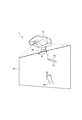
図1は、本発明を適用した実施形態に係るプロジェクションシステム1の構成を示す図である。プロジェクションシステム1は、スクリーンSC(投射面)の上方に設置されたプロジェクター10と、スクリーンSCの上部に設置された光出射装置60(光出射部)とを備える。
Hereinafter, embodiments of the present invention will be described with reference to the drawings.
FIG. 1 is a diagram showing a configuration of a projection system 1 according to an embodiment to which the present invention is applied. The projection system 1 includes a projector 10 installed above a screen SC (projection surface) and a light emitting device 60 (light emitting unit) installed above the screen SC.

プロジェクター10はスクリーンSCの直上または斜め上方に設置され、斜め下方のスクリーンSCに向けて画像を投射する。また、本実施形態で例示するスクリーンSCは、壁面に固定され、或いは床面に立設された、平板または幕である。本発明はこの例に限定されず、壁面をスクリーンSCとして使用することも可能である。この場合、スクリーンSCとして使用される壁面の上部にプロジェクター10及び光出射装置60を取り付けるとよい。   The projector 10 is installed directly above or obliquely above the screen SC and projects an image toward the screen SC obliquely below. Further, the screen SC exemplified in the present embodiment is a flat plate or a curtain fixed to a wall surface or standing on a floor surface. The present invention is not limited to this example, and the wall surface can be used as the screen SC. In this case, the projector 10 and the light emitting device 60 may be attached to the upper part of the wall surface used as the screen SC.

プロジェクター10は、PC(パーソナルコンピューター)、ビデオ再生装置、DVD再生装置等の外部の画像供給装置に接続され、この画像供給装置から供給されるアナログ画像信号またはデジタル画像データに基づき、スクリーンSCに画像を投射する。また、プロジェクター10は、内蔵する記憶部110(図2)や外部接続される記憶媒体に記憶された画像データを読み出して、この画像データに基づきスクリーンSCに画像を表示する構成としてもよい。
光出射装置60は、固体光源からなる光源部61(図2)を有し、光源部61が発する光(本実施形態では赤外光)をスクリーンSCに沿って拡散させて出射(照射)する。光出射装置60の出射範囲を図1に角度θで示す。光出射装置60はスクリーンSCの上端より上に設置され、下向きに角度θの範囲に光を出射し、この光はスクリーンSCに沿う光の層を形成する。本実施形態では角度θはほぼ180度に達し、スクリーンSCのほぼ全体に、光の層が形成される。スクリーンSCの表面と光の層とは近接していることが好ましく、本実施形態では、スクリーンSCの表面と光の層との距離は概ね10mm〜1mmの範囲内である。
The projector 10 is connected to an external image supply device such as a PC (personal computer), a video reproduction device, a DVD reproduction device, and the like, and an image is displayed on the screen SC based on an analog image signal or digital image data supplied from the image supply device. Project. The projector 10 may be configured to read out image data stored in a built-in storage unit 110 (FIG. 2) or an externally connected storage medium and display an image on the screen SC based on the image data.
The light emitting device 60 includes a light source unit 61 (FIG. 2) that is a solid light source, and diffuses (emits) light emitted from the light source unit 61 (infrared light in the present embodiment) along the screen SC. . The emission range of the light emitting device 60 is shown in FIG. The light emitting device 60 is installed above the upper end of the screen SC and emits light downward in the range of the angle θ, and this light forms a layer of light along the screen SC. In this embodiment, the angle θ reaches approximately 180 degrees, and a light layer is formed on almost the entire screen SC. The surface of the screen SC and the light layer are preferably close to each other. In this embodiment, the distance between the surface of the screen SC and the light layer is approximately in the range of 10 mm to 1 mm.

プロジェクションシステム1は、スクリーンSCに対する指示操作が行われた場合に、指示位置をプロジェクター10によって検出する。
指示操作に利用される指示体は、ペン型の指示体70(発光指示体)を用いることができる。指示体70の先端部71は、押圧された場合に動作する操作スイッチ75(図2)を内蔵しているので、先端部71を壁やスクリーンSCに押しつける操作がされると操作スイッチ75がオンになる。指示体70は、ユーザーが棒状の軸部72を手に持って、先端部71をスクリーンSCに接触させるように操作され、先端部71をスクリーンSCに押しつける操作も行われる。先端部71には、赤外光を発する送受信部74(図2)を備える。プロジェクター10は、指示体70が発する赤外光に基づき、先端部71の位置を、指示位置として検出する。
The projection system 1 detects the indicated position by the projector 10 when an instruction operation is performed on the screen SC.
As the indicator used for the instruction operation, a pen-type indicator 70 (light emission indicator) can be used. Since the distal end portion 71 of the indicator 70 incorporates an operation switch 75 (FIG. 2) that operates when pressed, the operation switch 75 is turned on when the distal end portion 71 is pressed against the wall or the screen SC. become. The indicator 70 is operated so that the user holds the rod-shaped shaft portion 72 in his / her hand and brings the tip portion 71 into contact with the screen SC, and an operation of pressing the tip portion 71 against the screen SC is also performed. The distal end portion 71 includes a transmission / reception unit 74 (FIG. 2) that emits infrared light. The projector 10 detects the position of the distal end portion 71 as the indication position based on the infrared light emitted from the indicator 70.

また、ユーザーの手指である指示体80で位置指示操作を行う場合、ユーザーは指をスクリーンSCに接触させる。この場合、指示体80がスクリーンSCに接触した位置が検出される。
すなわち、指示体80の先端(例えば、指先)がスクリーンSCに接触するときに、光出射装置60が形成する光の層を遮る。このとき、光出射装置60が出射した光が指示体80に当たって反射し、反射光は指示体80から光出射装置60に向かって進む。プロジェクター10は、スクリーンSC側からの光、すなわち下方からの光を後述する位置検出部50により検出する機能を有するので、指示体80の反射光を検出できる。プロジェクター10は、指示体80で反射した反射光を検出することにより、指示体80によるスクリーンSCへの指示操作を検出する。また、プロジェクター10は指示体80により指示された指示位置を検出する。
光出射装置60が出射する光の層はスクリーンSCに近接しているので、指示体80において光が反射する位置は、スクリーンSCに最も近い先端、或いは指示位置と見なすことができる。このため、指示体80の反射光に基づき指示位置を特定できる。
Further, when a position indicating operation is performed with the indicator 80 that is a user's finger, the user brings the finger into contact with the screen SC. In this case, the position where the indicator 80 contacts the screen SC is detected.
That is, when the tip (for example, fingertip) of the indicator 80 contacts the screen SC, the light layer formed by the light emitting device 60 is blocked. At this time, the light emitted from the light emitting device 60 strikes the indicator 80 and is reflected, and the reflected light travels from the indicator 80 toward the light emitting device 60. Since the projector 10 has a function of detecting light from the screen SC side, that is, light from below by the position detection unit 50 described later, the reflected light of the indicator 80 can be detected. The projector 10 detects an instruction operation on the screen SC by the indicator 80 by detecting the reflected light reflected by the indicator 80. Further, the projector 10 detects the indicated position indicated by the indicator 80.
Since the light layer emitted from the light emitting device 60 is close to the screen SC, the position where the light is reflected by the indicator 80 can be regarded as the tip closest to the screen SC or the indication position. For this reason, the indicated position can be specified based on the reflected light of the indicator 80.

プロジェクションシステム1は、インタラクティブホワイトボードシステムとして機能し、操作者が指示体70、80により行った指示操作を検出して、指示位置を投射画像に反映させる。
具体的には、プロジェクションシステム1は、指示位置に図形を描画したり文字や記号を配置したりする処理、指示位置の軌跡に沿って図形を描画する処理、描画した図形や配置した文字または記号を消去する処理等を行う。また、スクリーンSCに描画された図形、配置された文字または記号を画像データとして保存することもでき、外部の装置に出力することもできる。
さらに、指示位置を検出することによりポインティングデバイスとして動作し、スクリーンSCにプロジェクター10が画像を投射する画像投射領域における指示位置の座標を出力してもよい。また、この座標を用いてGUI(Graphical User Interface)操作を行ってもよい。
The projection system 1 functions as an interactive whiteboard system, detects an instruction operation performed by the operator using the indicators 70 and 80, and reflects the indicated position on the projection image.
Specifically, the projection system 1 performs a process of drawing a graphic or placing a character or a symbol at a designated position, a process of drawing a graphic along the locus of the designated position, a drawn figure, a placed character or symbol The process etc. which erase is performed. In addition, graphics drawn on the screen SC, arranged characters or symbols can be stored as image data, and can be output to an external device.
Further, it may operate as a pointing device by detecting the designated position, and output the coordinates of the designated position in the image projection area where the projector 10 projects an image on the screen SC. Further, a GUI (Graphical User Interface) operation may be performed using these coordinates.

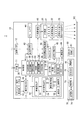
図2は、プロジェクションシステム1を構成する各部の機能ブロック図である。
プロジェクター10は、外部の装置に接続されるインターフェイスとして、I/F(インターフェイス)部11及び画像I/F(インターフェイス)部12を備える。I/F部11及び画像I/F部12は有線接続用のコネクターを備え、上記コネクターに対応するインターフェイス回路を備えていてもよい。また、I/F部11及び画像I/F部12は、無線通信インターフェイスを備えていてもよい。有線接続用のコネクター及びインターフェイス回路としては有線LAN、IEEE1394、USB等に準拠したものが挙げられる。また、無線通信インターフェイスとしては無線LANやBluetooth(登録商標)等に準拠したものが挙げられる。画像I/F部12には、HDMI(登録商標)インターフェイス等の画像データ用のインターフェイスを用いることもできる。画像I/F部12は、音声データが入力されるインターフェイスを備えてもよい。
FIG. 2 is a functional block diagram of each part constituting the projection system 1.
The projector 10 includes an I / F (interface) unit 11 and an image I / F (interface) unit 12 as interfaces connected to external devices. The I / F unit 11 and the image I / F unit 12 may include a connector for wired connection, and may include an interface circuit corresponding to the connector. The I / F unit 11 and the image I / F unit 12 may include a wireless communication interface. Examples of the connector and interface circuit for wired connection include those based on wired LAN, IEEE 1394, USB, and the like. Examples of the wireless communication interface include those that comply with a wireless LAN, Bluetooth (registered trademark), or the like. The image I / F unit 12 may be an image data interface such as an HDMI (registered trademark) interface. The image I / F unit 12 may include an interface through which audio data is input.

I/F部11は、PC等の外部の装置との間で各種データを送受信するインターフェイスである。I/F部11は、画像の投射に関する制御データ、プロジェクター10の動作を設定する設定データ、プロジェクター10が検出した指示位置の座標データ等を入出力する。後述する制御部30は、I/F部11を介して外部の装置とデータを送受信する機能を有する。
画像I/F部12は、デジタル画像データが入力されるインターフェイスである。本実施形態のプロジェクター10は、画像I/F部12を介して入力されるデジタル画像データに基づき画像を投射する。なお、プロジェクター10は、アナログ画像信号に基づき画像を投射する機能を備えてもよく、この場合、画像I/F部12は、アナログ画像用のインターフェイスと、アナログ画像信号をデジタル画像データに変換するA/D変換回路とを備えてもよい。
The I / F unit 11 is an interface that transmits and receives various data to and from an external device such as a PC. The I / F unit 11 inputs and outputs control data related to image projection, setting data for setting the operation of the projector 10, coordinate data of the designated position detected by the projector 10, and the like. The control unit 30 described later has a function of transmitting / receiving data to / from an external device via the I / F unit 11.
The image I / F unit 12 is an interface through which digital image data is input. The projector 10 of the present embodiment projects an image based on digital image data input via the image I / F unit 12. The projector 10 may have a function of projecting an image based on the analog image signal. In this case, the image I / F unit 12 converts the analog image signal into digital image data and an analog image interface. And an A / D conversion circuit.

プロジェクター10は、光学的な画像の形成を行う投射部20を備える。投射部20は、光源部21、光変調装置22、および投射光学系23を有する。光源部21は、キセノンランプ、超高圧水銀ランプ、LED(Light Emitting Diode)、或いはレーザー光源等からなる光源を備える。また、光源部21は、光源が発した光を光変調装置22に導くリフレクターおよび補助リフレクターを備えていてもよい。さらに、投射光の光学特性を高めるためのレンズ群(図示略)、偏光板、或いは光源が発した光の光量を光変調装置22に至る経路上で低減させる調光素子等を備えていてもよい。
光変調装置22は、例えばRGBの三原色に対応した3枚の透過型液晶パネルを備え、この液晶パネルを透過する光を変調して画像光を生成する。光源部21からの光はRGBの3色の色光に分離され、各色光は対応する各液晶パネルに入射する。各液晶パネルを通過して変調された色光はクロスダイクロイックプリズム等の合成光学系によって合成され、投射光学系23に射出される。
The projector 10 includes a projection unit 20 that forms an optical image. The projection unit 20 includes a light source unit 21, a light modulation device 22, and a projection optical system 23. The light source unit 21 includes a light source including a xenon lamp, an ultra high pressure mercury lamp, an LED (Light Emitting Diode), a laser light source, or the like. The light source unit 21 may include a reflector and an auxiliary reflector that guide light emitted from the light source to the light modulation device 22. Further, a lens group (not shown) for enhancing the optical characteristics of the projection light, a polarizing plate, or a dimming element that reduces the amount of light emitted from the light source on the path to the light modulation device 22 may be provided. Good.
The light modulation device 22 includes, for example, three transmissive liquid crystal panels corresponding to the three primary colors of RGB, and generates image light by modulating light transmitted through the liquid crystal panel. The light from the light source unit 21 is separated into three color lights of RGB, and each color light enters each corresponding liquid crystal panel. The color light modulated by passing through each liquid crystal panel is combined by a combining optical system such as a cross dichroic prism and emitted to the projection optical system 23.

投射光学系23は、光変調装置22により変調された画像光をスクリーンSC方向へ導き、スクリーンSC上に結像させるレンズ群を備える。また、投射光学系23は、スクリーンSCの投射画像の拡大・縮小および焦点の調整を行うズーム機構、フォーカスの調整を行うフォーカス調整機構を備えていてもよい。プロジェクター10が短焦点型である場合、投射光学系23に、画像光をスクリーンSCに向けて反射する凹面鏡を備えていてもよい。   The projection optical system 23 includes a lens group that guides the image light modulated by the light modulation device 22 toward the screen SC and forms an image on the screen SC. Further, the projection optical system 23 may include a zoom mechanism for enlarging / reducing the projected image on the screen SC and adjusting the focus, and a focus adjusting mechanism for adjusting the focus. When the projector 10 is a short focus type, the projection optical system 23 may include a concave mirror that reflects image light toward the screen SC.

投射部20には、制御部30の制御に従って光源部21を点灯させる光源駆動部45、及び、制御部30の制御に従って光変調装置22を動作させる光変調装置駆動部46が接続される。光源駆動部45は、光源部21の点灯/消灯の切り替えを行い、光源部21の光量を調整する機能を有していてもよい。   The projection unit 20 is connected to a light source drive unit 45 that turns on the light source unit 21 according to the control of the control unit 30 and a light modulation device drive unit 46 that operates the light modulation device 22 according to the control of the control unit 30. The light source drive unit 45 may have a function of switching on / off the light source unit 21 and adjusting the light amount of the light source unit 21.

プロジェクター10は、投射部20が投射する画像を処理する画像処理系を備える。この画像処理系は、プロジェクター10を制御する制御部30、記憶部110、操作検出部17、画像処理部40、光源駆動部45、及び光変調装置駆動部46を含む。また、画像処理部40にはフレームメモリー44が接続され、制御部30には姿勢センサー47、出射装置駆動部48、及び位置検出部50が接続される。これらの各部を画像処理系に含めてもよい。   The projector 10 includes an image processing system that processes an image projected by the projection unit 20. The image processing system includes a control unit 30 that controls the projector 10, a storage unit 110, an operation detection unit 17, an image processing unit 40, a light source driving unit 45, and a light modulation device driving unit 46. In addition, a frame memory 44 is connected to the image processing unit 40, and an attitude sensor 47, an emission device driving unit 48, and a position detection unit 50 are connected to the control unit 30. These units may be included in the image processing system.

制御部30は、所定の制御プログラム111を実行することにより、プロジェクター10の各部を制御する。記憶部110は、制御部30が実行する制御プログラム111、および、制御部30が処理するデータを不揮発的に記憶する。記憶部110は、プロジェクター10の動作を設定するための画面の設定画面データ112、及び、設定画面データ112を利用して設定された内容を示す設定データ113を記憶する。   The control unit 30 controls each unit of the projector 10 by executing a predetermined control program 111. The storage unit 110 stores the control program 111 executed by the control unit 30 and the data processed by the control unit 30 in a nonvolatile manner. The storage unit 110 stores setting screen data 112 of a screen for setting the operation of the projector 10 and setting data 113 indicating the contents set using the setting screen data 112.

画像処理部40は、制御部30の制御に従って、画像I/F部12を介して入力される画像データを処理し、光変調装置駆動部46に画像信号を出力する。画像処理部40が実行する処理は、3D(立体)画像と2D(平面)画像の判別処理、解像度変換処理、フレームレート変換処理、歪み補正処理、デジタルズーム処理、色調補正処理、輝度補正処理等である。画像処理部40は、制御部30により指定された処理を実行し、必要に応じて、制御部30から入力されるパラメーターを使用して処理を行う。また、上記のうち複数の処理を組み合わせて実行することも勿論可能である。
画像処理部40はフレームメモリー44を有する。画像処理部40は、画像入力I/F12から入力される画像データをフレームメモリー44に展開して、展開した画像データに対し上記の各種処理を実行する。画像処理部40は、処理後の画像データをフレームメモリー44から読み出して、この画像データに対応するR、G、Bの画像信号を生成し、光変調装置駆動部46に出力する。
光変調装置駆動部46、光変調装置22の液晶パネルに接続される。光変調装置駆動部46は、画像処理部40から入力される画像信号に基づいて液晶パネルを駆動し、各液晶パネルに画像を描画する。
The image processing unit 40 processes the image data input via the image I / F unit 12 under the control of the control unit 30, and outputs an image signal to the light modulation device driving unit 46. The processing executed by the image processing unit 40 includes 3D (stereoscopic) image and 2D (planar) image discrimination processing, resolution conversion processing, frame rate conversion processing, distortion correction processing, digital zoom processing, color tone correction processing, luminance correction processing, and the like. is there. The image processing unit 40 executes processing designated by the control unit 30 and performs processing using parameters input from the control unit 30 as necessary. Of course, it is also possible to execute a combination of a plurality of processes.
The image processing unit 40 has a frame memory 44. The image processing unit 40 expands the image data input from the image input I / F 12 in the frame memory 44, and executes the various processes described above on the expanded image data. The image processing unit 40 reads out the processed image data from the frame memory 44, generates R, G, B image signals corresponding to the image data, and outputs them to the light modulation device driving unit 46.
The light modulation device drive unit 46 and the liquid crystal panel of the light modulation device 22 are connected. The light modulator driving unit 46 drives the liquid crystal panel based on the image signal input from the image processing unit 40 and draws an image on each liquid crystal panel.

操作検出部17は、入力デバイスとして機能するリモコン受光部18および操作パネル19に接続され、リモコン受光部18及び操作パネル19を介した操作を検出する。
リモコン受光部18は、プロジェクター10の操作者が使用するリモコン(図示略)がボタン操作に対応して送信した赤外線信号を、リモコン受光部18によって受光する。リモコン受光部18は、上記リモコンから受光した赤外線信号をデコードして、上記リモコンにおける操作内容を示す操作データを生成し、制御部30に出力する。
操作パネル19は、プロジェクター10の外装筐体に設けられ、各種スイッチおよびインジケーターランプを有する。操作検出部17は、制御部30の制御に従い、プロジェクター10の動作状態や設定状態に応じて操作パネル19のインジケーターランプを適宜点灯及び消灯させる。この操作パネル19のスイッチが操作されると、操作されたスイッチに対応する操作データが操作検出部17から制御部30に出力される。
The operation detection unit 17 is connected to the remote control light receiving unit 18 and the operation panel 19 that function as an input device, and detects an operation through the remote control light reception unit 18 and the operation panel 19.
The remote control light receiving unit 18 receives an infrared signal transmitted in response to a button operation by a remote control (not shown) used by the operator of the projector 10 by the remote control light receiving unit 18. The remote control light receiving unit 18 decodes the infrared signal received from the remote control, generates operation data indicating the operation content of the remote control, and outputs the operation data to the control unit 30.
The operation panel 19 is provided in the exterior housing of the projector 10 and has various switches and indicator lamps. The operation detection unit 17 appropriately turns on and off the indicator lamp of the operation panel 19 according to the operation state and setting state of the projector 10 according to the control of the control unit 30. When the switch of the operation panel 19 is operated, operation data corresponding to the operated switch is output from the operation detection unit 17 to the control unit 30.

出射装置駆動部48は、接続部49を介して光出射装置60に接続される。接続部49は、例えば複数のピンを有するコネクターであり、接続部49を介して光出射装置60がプロジェクター10に有線接続される。接続部49のピンは、パルス信号、電源、GND等にアサインされる。出射装置駆動部48は、制御部30の制御に従ってパルス信号を生成し、接続部49を介して光出射装置60に出力する。このパルス信号は光源部61の点灯をPWM制御する信号であり、パルスの周波数、オン期間、オフ期間は制御部30により制御される。光源部61は、制御部30が指定したタイミングで点灯及び消灯する。また、パルスのオン期間とオフ期間とのデューティを調整することによって、制御部30は、光源部61の光量を調整できる。また、出射装置駆動部48は接続部49を介して光出射装置60に電源を供給する。   The emission device driving unit 48 is connected to the light emission device 60 via the connection unit 49. The connection unit 49 is a connector having a plurality of pins, for example, and the light emitting device 60 is wired to the projector 10 via the connection unit 49. The pins of the connection unit 49 are assigned to a pulse signal, a power supply, GND, and the like. The emission device driving unit 48 generates a pulse signal according to the control of the control unit 30 and outputs the pulse signal to the light emission device 60 via the connection unit 49. This pulse signal is a signal for PWM control of lighting of the light source unit 61, and the frequency, on period, and off period of the pulse are controlled by the control unit 30. The light source unit 61 is turned on and off at the timing specified by the control unit 30. Further, the control unit 30 can adjust the light amount of the light source unit 61 by adjusting the duty between the on period and the off period of the pulse. Further, the emission device driving unit 48 supplies power to the light emission device 60 through the connection unit 49.

光出射装置60は、図1に示すように略箱形のケースに、光源部61、及び光学部品を収容して構成される。本実施形態の光出射装置60は、光源部61に固体光源を備える。固体光源としては、赤外LEDや赤外レーザーダイオードが挙げられる。固体光源が発する赤外光は、平行化レンズ及びパウエルレンズによって拡散され、スクリーンSCに沿った面を形成する。また、光源部61が複数の固体光源を備え、これら複数の固体光源が発する光をそれぞれ拡散させることによって、スクリーンSCの画像投射範囲を覆うように光の層を形成してもよい。また、光出射装置60は、光源部61が発する光の層とスクリーンSCとの間の距離や角度を調整する調整機構を備えていてもよい。   As shown in FIG. 1, the light emitting device 60 is configured by housing a light source unit 61 and optical components in a substantially box-shaped case. The light emitting device 60 of this embodiment includes a solid light source in the light source unit 61. Examples of solid light sources include infrared LEDs and infrared laser diodes. Infrared light emitted from the solid-state light source is diffused by the collimating lens and the Powell lens to form a surface along the screen SC. The light source unit 61 may include a plurality of solid light sources, and a light layer may be formed so as to cover the image projection range of the screen SC by diffusing light emitted from the plurality of solid light sources. The light emitting device 60 may include an adjustment mechanism that adjusts the distance and angle between the light layer emitted from the light source unit 61 and the screen SC.

光出射装置60は、接続部49に接続されるケーブルにより供給されるパルス信号および電源により、光源部61を点灯させる。例えば、ケーブルにより入力されるパルス信号および電源を直接、光源部61に入力してもよい。従って、光源部61の固体光源が点灯及び消灯するタイミングは、出射装置駆動部48により制御できる。制御部30は、出射装置駆動部48を制御して、後述する撮像部51が撮影を行うタイミングに同期して光源部61を点灯させる。 Light emitting device 60, the pulse signal and the power supply is more supplied to the cable connected to the connection portion 49, thereby turning on the light source unit 61. For example, a pulse signal and power are more input to cable may be directly input to the light source unit 61. Therefore, the timing at which the solid state light source of the light source unit 61 is turned on and off can be controlled by the emission device driving unit 48. The control unit 30 controls the emission device driving unit 48 to turn on the light source unit 61 in synchronization with the timing when the imaging unit 51 described later performs imaging.

位置検出部50(検出部)は、指示体70、80による操作を検出する。位置検出部50は、撮像部51、送信部52、撮影制御部53、指示体検出部54、および座標算出部55の各部を備えて構成される。位置検出部50は、操作検出手段として機能する。
撮像部51は、撮像光学系、撮像素子、インターフェイス回路等を有し、投射光学系23の投射方向を撮影する。撮像部51の撮像光学系は、投射光学系23と同じ方向を向いて配置され、投射光学系23がスクリーンSC上に画像を投射する範囲をカバーする画角を有する。また、撮像素子は、赤外領域及び可視光領域の光を受光するCCDやCMOSが挙げられる。撮像部51は、撮像素子に入射する光の一部を遮るフィルターを備えてもよく、例えば、赤外光を受光させる場合に、主に赤外領域の光を透過するフィルターを撮像素子の前に配置させてもよい。また、撮像部51のインターフェイス回路は、撮像素子の検出値を読み出して出力する。
The position detection unit 50 (detection unit) detects an operation performed by the indicators 70 and 80. The position detection unit 50 includes an imaging unit 51, a transmission unit 52, an imaging control unit 53, a pointer detection unit 54, and a coordinate calculation unit 55. The position detection unit 50 functions as an operation detection unit.
The imaging unit 51 includes an imaging optical system, an imaging element, an interface circuit, and the like, and images the projection direction of the projection optical system 23. The imaging optical system of the imaging unit 51 is disposed in the same direction as the projection optical system 23, and has an angle of view that covers a range in which the projection optical system 23 projects an image on the screen SC. Examples of the imaging device include a CCD and a CMOS that receive light in the infrared region and the visible light region. The imaging unit 51 may include a filter that blocks a part of the light incident on the imaging element. For example, when receiving infrared light, a filter that mainly transmits infrared light is provided in front of the imaging element. May be arranged. Further, the interface circuit of the imaging unit 51 reads and outputs the detection value of the imaging element.

撮影制御部53は、撮像部51により撮影を実行させて撮影画像データを生成する。撮像素子が可視光による撮影を行うと、スクリーンSC上に投射された画像が撮影される。この撮影画像は、例えば投射画像の台形歪みや糸巻き型歪みを補正する歪み補正処理に使用される。また、撮影制御部53は、撮像部51により赤外光を撮影することができ、この場合の撮影画像には指示体70が発する赤外光(赤外線信号)や、指示体80に反射した反射光が写る。   The imaging control unit 53 causes the imaging unit 51 to perform imaging and generates captured image data. When the imaging device performs imaging with visible light, an image projected on the screen SC is captured. This captured image is used for distortion correction processing for correcting, for example, trapezoidal distortion or pincushion distortion of the projected image. In addition, the imaging control unit 53 can capture infrared light by the imaging unit 51, and in this case, the captured image includes infrared light (infrared signal) emitted from the indicator 70 and reflection reflected by the indicator 80. Light is reflected.

指示体検出部54は、撮影制御部53が撮影した撮影画像データに基づいて指示体70、80の指示位置を検出する。指示体検出部54は、撮影制御部53が撮像部51によって赤外光の撮影を実行させた場合の撮影画像データから、指示体70が発した赤外光の像、及び/又は、指示体80に反射した反射光の像を検出する。さらに、指示体検出部54は、検出した像を、指示体70が発した光の像であるか、指示体80の反射光の像であるか判別してもよい。
座標算出部55は、指示体検出部54が検出した像の位置に基づき、撮影画像データにおける指示体70、80の指示位置の座標を算出して、制御部30に出力する。座標算出部55は、また、投射部20が投射した投射画像における指示体70、80の指示位置の座標を算出して、制御部30に出力してもよい。さらに、座標算出部55は、画像処理部40がフレームメモリー44に描画した画像データにおける指示体70、80の指示位置の座標や、画像I/F部12の入力画像データにおける指示体70、80の指示位置の座標を、算出してもよい。
The indicator detection unit 54 detects the indication positions of the indicators 70 and 80 based on the captured image data captured by the imaging control unit 53. The indicator detection unit 54 includes an infrared light image and / or indicator emitted by the indicator 70 from the captured image data when the imaging control unit 53 causes the imaging unit 51 to perform infrared imaging. An image of the reflected light reflected by 80 is detected. Further, the indicator detection unit 54 may determine whether the detected image is an image of light emitted from the indicator 70 or an image of reflected light from the indicator 80.
The coordinate calculation unit 55 calculates the coordinates of the pointing positions of the pointers 70 and 80 in the captured image data based on the position of the image detected by the pointer detection unit 54 and outputs the calculated coordinates to the control unit 30. The coordinate calculation unit 55 may also calculate the coordinates of the indication positions of the indicators 70 and 80 in the projection image projected by the projection unit 20 and output them to the control unit 30. Further, the coordinate calculation unit 55 is configured to display the coordinates of the pointing positions of the indicators 70 and 80 in the image data drawn by the image processing unit 40 in the frame memory 44 and the indicators 70 and 80 in the input image data of the image I / F unit 12. The coordinates of the designated position may be calculated.

送信部52は、指示体検出部54の制御に従って、指示体70に対して赤外線信号を送信する。送信部52は、赤外LED等の光源を有し、この光源を指示体検出部54の制御に従って点灯及び消灯させる。   The transmission unit 52 transmits an infrared signal to the indicator 70 according to the control of the indicator detection unit 54. The transmission unit 52 has a light source such as an infrared LED, and turns on and off the light source according to the control of the indicator detection unit 54.

また、指示体70は、制御部73、送受信部74、操作スイッチ75、及び電源部76を備え、これらの各部は軸部72(図1)に収容される。制御部73は、送受信部74及び操作スイッチ75に接続され、操作スイッチ75のオン/オフ状態を検出する。送受信部74は、赤外LED等の光源と、赤外光を受光する受光素子とを備え、制御部73の制御に従って光源を点灯及び消灯させるとともに、受光素子の受光状態を示す信号を制御部73に出力する。
電源部76は、電源として乾電池または二次電池を有し、制御部73、送受信部74、及び操作スイッチ75の各部に電力を供給する。
指示体70は、電源部76からの電源供給をオン/オフする電源スイッチを備えていてもよい。
Moreover, the indicator 70 is provided with the control part 73, the transmission / reception part 74, the operation switch 75, and the power supply part 76, and these each part is accommodated in the axial part 72 (FIG. 1). The control unit 73 is connected to the transmission / reception unit 74 and the operation switch 75 and detects the on / off state of the operation switch 75. The transmission / reception unit 74 includes a light source such as an infrared LED and a light receiving element that receives infrared light. To 73.
The power supply unit 76 includes a dry battery or a secondary battery as a power supply, and supplies power to the control unit 73, the transmission / reception unit 74, and the operation switch 75.
The indicator 70 may include a power switch that turns on / off the power supply from the power supply unit 76.

ここで、位置検出部50と指示体70との相互の通信により、撮像部51の撮影画像データから指示体70を特定する方法について説明する。
制御部30は、指示体70による位置指示操作を検出する場合に、指示体検出部54を制御して、送信部52から同期用の信号を送信させる。すなわち、指示体検出部54は、制御部30の制御に従って、送信部52の光源を所定の周期で点灯させる。送信部52が周期的に発する赤外光が、位置検出部50と指示体70とを同期させる同期信号として機能する。
一方、制御部73は、電源部76から電源の供給が開始され、所定の初期化動作を行った後、プロジェクター10の送信部52が発する赤外光を、送受信部74により受光する。送信部52が周期的に発する赤外光を送受信部74により受光すると、制御部73は、この赤外光のタイミングに同期させて、予め設定されたパターンで、送受信部74の光源を点灯(発光)させる。この点灯のパターンは、光源の点灯と消灯をデータのオンとオフに対応させて、指示体70に固有のデータを表す。制御部73は設定されたパターンの点灯時間及び消灯時間に従って光源を点灯及び消灯させる。制御部73は、電源部76から電源が供給されている間、上記のパターンを繰り返し実行する。
つまり、位置検出部50は指示体70に対し、同期用の赤外線信号を周期的に送信し、指示体70は、位置検出部50が送信する赤外線信号に同期して、予め設定された赤外線信号を送信する。
Here, a method of specifying the indicator 70 from the captured image data of the imaging unit 51 by mutual communication between the position detection unit 50 and the indicator 70 will be described.
When detecting the position pointing operation by the pointer 70, the control unit 30 controls the pointer detection unit 54 to transmit a synchronization signal from the transmission unit 52. That is, the indicator detection unit 54 turns on the light source of the transmission unit 52 at a predetermined period in accordance with the control of the control unit 30. The infrared light periodically emitted from the transmission unit 52 functions as a synchronization signal that synchronizes the position detection unit 50 and the indicator 70.
On the other hand, after the supply of power from the power supply unit 76 is started and a predetermined initialization operation is performed, the control unit 73 receives infrared light emitted from the transmission unit 52 of the projector 10 by the transmission / reception unit 74. When the transmission / reception unit 74 receives infrared light periodically generated by the transmission unit 52, the control unit 73 lights the light source of the transmission / reception unit 74 in a preset pattern in synchronization with the timing of the infrared light ( Luminescence). This lighting pattern represents data specific to the indicator 70 by turning on and off the light source corresponding to ON and OFF of the data. The control unit 73 turns on and off the light source in accordance with the set pattern turn-on time and turn-off time. The control unit 73 repeatedly executes the above pattern while power is supplied from the power supply unit 76.
That is, the position detection unit 50 periodically transmits an infrared signal for synchronization to the indicator 70, and the indicator 70 synchronizes with the infrared signal transmitted by the position detection unit 50 to set the infrared signal set in advance. Send.

位置検出部50の撮影制御部53は、撮像部51による撮影タイミングを、指示体70が点灯するタイミングに合わせる制御を行う。この撮影タイミングは、指示体検出部54が送信部52を点灯させるタイミングに基づいて決定される。指示体検出部54は、撮像部51の撮影画像データに指示体70の光の像が写っているか否かにより、指示体70が点灯するパターンを特定できる。ここで、制御部30は、指示体70が赤外線信号を送信(発光)するタイミングを、撮像部51の撮影タイミングに同期させてもよい。この制御は、位置検出部50が指示体70に送信する同期用の赤外線信号の送信タイミングを、撮影制御部53が撮像部51に撮影を実行させるタイミングを基準として調整することで、容易に実現できる。
指示体70が点灯するパターンは、指示体70の固体毎に固有のパターン、または、複数の指示体70に共通のパターンと、個体毎に固有のパターンとを含むものとすることができる。この場合、指示体検出部54は、撮影画像データに複数の指示体70が発する赤外光の像が含まれる場合に、各々の像を、異なる指示体70の像として区別できる。
The shooting control unit 53 of the position detection unit 50 performs control to match the shooting timing of the imaging unit 51 with the timing when the indicator 70 is turned on. This shooting timing is determined based on the timing when the indicator detection unit 54 turns on the transmission unit 52. The indicator detection unit 54 can specify a pattern in which the indicator 70 is turned on depending on whether or not the image of the light of the indicator 70 is captured in the captured image data of the imaging unit 51. Here, the control unit 30 may synchronize the timing at which the indicator 70 transmits (emits) an infrared signal with the imaging timing of the imaging unit 51. This control is easily realized by adjusting the transmission timing of the synchronization infrared signal transmitted from the position detection unit 50 to the indicator 70 with reference to the timing at which the imaging control unit 53 causes the imaging unit 51 to perform imaging. it can.
The pattern in which the indicator 70 is lit may include a pattern unique to each indicator 70, a pattern common to the plurality of indicators 70, and a pattern unique to each individual. In this case, the indicator detection unit 54 can distinguish each image as an image of a different indicator 70 when the captured image data includes images of infrared light emitted from the plurality of indicators 70.

また、制御部30は、出射装置駆動部48を制御して、光源部61の点灯のタイミングを撮像部51の撮影のタイミングに同期させる。光源部61が、撮像部51の撮影タイミングに合わせてパルス点灯すると、指示体80がスクリーンSC上を指し示す場合には、撮像部51の撮影画像に指示体80の反射光が写る。光源部61を、指示体70の点灯のタイミングと区別できるパターンで点灯させれば、指示体検出部54は、撮影画像データに写る像が指示体70であるか指示体80であるかを判定できる。
例えば、撮像部51の撮影タイミングの全てに同期して、光源部61を点灯させ、指示体70は「1010101010」(1は点灯を、0は消灯を示す)のパターンで点灯する場合を考える。この場合、連続する複数の撮影画像データを比較すれば、指示体70の像と指示体80の像とを容易に区別できる。従って、指示体70と指示体80とが混在して、スクリーンSCに対する位置指示操作を行う場合に、指示体70の指示操作と、指示体80の指示操作とを区別して検出できる。
In addition, the control unit 30 controls the emission device driving unit 48 to synchronize the lighting timing of the light source unit 61 with the imaging timing of the imaging unit 51. When the light source unit 61 turns on the pulse in synchronization with the imaging timing of the imaging unit 51, the reflected light of the indicator 80 appears in the captured image of the imaging unit 51 when the indicator 80 points on the screen SC. When the light source unit 61 is turned on in a pattern that can be distinguished from the lighting timing of the indicator 70, the indicator detection unit 54 determines whether the image shown in the captured image data is the indicator 70 or the indicator 80. it can.
For example, consider a case where the light source unit 61 is turned on in synchronization with all the shooting timings of the imaging unit 51 and the indicator 70 is turned on in a pattern of “1010101010” (1 indicates lighting and 0 indicates light extinction). In this case, the image of the indicator 70 and the image of the indicator 80 can be easily distinguished by comparing a plurality of continuous captured image data. Therefore, when the pointer 70 and the pointer 80 are mixed and a position pointing operation is performed on the screen SC, the pointing operation of the pointer 70 and the pointing operation of the pointer 80 can be detected separately.

さらに、指示体70が備える制御部73は、操作スイッチ75の操作状態に応じて、送受信部74を点灯させるパターンを切り替える。このため、指示体検出部54は、複数の撮影画像データに基づいて、指示体70の操作状態、すなわち先端部71がスクリーンSCに押しつけられているか否かを判定できる。   Further, the control unit 73 included in the indicator 70 switches the pattern for lighting the transmission / reception unit 74 according to the operation state of the operation switch 75. For this reason, the indicator detection unit 54 can determine the operating state of the indicator 70, that is, whether or not the distal end portion 71 is pressed against the screen SC, based on a plurality of captured image data.

姿勢センサー47は、加速度センサーやジャイロセンサー等により構成され、制御部30に対して検出値を出力する。姿勢センサー47はプロジェクター10の本体に対して、プロジェクター10の設置方向を識別可能なように固定される。   The attitude sensor 47 is configured by an acceleration sensor, a gyro sensor, or the like, and outputs a detection value to the control unit 30. The attitude sensor 47 is fixed to the main body of the projector 10 so that the installation direction of the projector 10 can be identified.

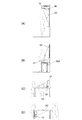
図3は、プロジェクター10の設置状態の例を示す図であり、(A)は吊り下げ設置、(B)は通常設置、(C)は机上設置、(D)は机上背面設置の各設置状態を示す。
(A)の吊り下げ設置は図1に示した設置状態と同一である。(B)の設置状態ではスクリーンSCの前方かつ下方にプロジェクター10を設置し、プロジェクター10が上向きに画像を投射する。この場合、光出射装置60の設置位置を、スクリーンSCの下方に符号60Aで示す位置に設置することが考えられる。しかしながら、光出射装置60から上向きに検出光を出射すると、検出光がユーザーの腕や背中等に遮られて、指示体80に届かないことがある。従って、図3(B)の設置状態は光出射装置60の使用には適さない。
図3(C)の机上設置状態では、机上の水平面がスクリーンSCとなっており、プロジェクター10は、スクリーンSCの一端側から画像を投射する。この場合、光出射装置60をプロジェクター10と同じ側に設置して、スクリーンSCの他端側に向けて検出光を出射すれば、図3(A)の吊り下げ設置状態と同様に指示体80の操作を検出できる。図3(D)の机上背面設置状態では、机上の水平面がスクリーンSCとなっており、プロジェクター10はスクリーンSCの背面側に設置されて背面投射を行う。指示体80の操作はスクリーンSCの表側、すなわち図中ではスクリーンSCの上側で行われる。このため、指示体80に検出光を出射し、指示体80で反射した反射光をプロジェクター10が検出できる位置はない。従って、図3(D)の設置状態は、光出射装置60の使用に適さない。
FIG. 3 is a diagram illustrating an example of an installation state of the projector 10. (A) is a hanging installation, (B) is a normal installation, (C) is a desktop installation, and (D) is a desktop rear installation. Indicates.
The hanging installation of (A) is the same as the installation state shown in FIG. In the installed state of (B), the projector 10 is installed in front and below the screen SC, and the projector 10 projects an image upward. In this case, it is conceivable that the installation position of the light emitting device 60 is installed at a position indicated by reference numeral 60A below the screen SC. However, when the detection light is emitted upward from the light emitting device 60, the detection light may be blocked by the user's arm, back, or the like and may not reach the indicator 80. Therefore, the installation state of FIG. 3B is not suitable for use of the light emitting device 60.
In the desktop installation state of FIG. 3C, the horizontal plane on the desk is the screen SC, and the projector 10 projects an image from one end side of the screen SC. In this case, if the light emitting device 60 is installed on the same side as the projector 10 and the detection light is emitted toward the other end of the screen SC, the indicator 80 as in the suspended installation state of FIG. Can be detected. 3D, the horizontal plane on the desk is the screen SC, and the projector 10 is installed on the back side of the screen SC and performs rear projection. The operation of the indicator 80 is performed on the front side of the screen SC, that is, on the upper side of the screen SC in the drawing. For this reason, there is no position where the projector 10 can detect the reflected light reflected by the indicator 80 by emitting the detection light to the indicator 80. Therefore, the installation state of FIG. 3D is not suitable for use of the light emitting device 60.

姿勢センサー47は、例えば、図3(A)〜(D)に示した4通りの設置状態を区別できるように、プロジェクター10の本体に設けられる。図3(B)の通常設置状態を基準にすると、図3(A)の設置状態ではプロジェクター10は上下が逆になり、図3(C)及び(D)ではプロジェクター10が倒立する。さらに、図3(C)と(D)ではプロジェクター10の上下方向が逆になる。このため、例えば姿勢センサー47が2軸のジャイロセンサーを備えれば、図3(A)〜(D)の4通りの設置状態を区別し、プロジェクター10の設置状態を制御部30が判定できる。また、例えば1軸のジャイロセンサーを、図3(A)〜(D)に示したスクリーンSCに対して検出軸を傾けて設置すれば、ジャイロセンサーの出力値に基づいて図3(A)〜(D)の4通りの設置状態を区別できる。加速度センサーを用いても、同様に、図3(A)〜(D)の4通りの設置状態を区別できる。   The attitude sensor 47 is provided in the main body of the projector 10 so that the four installation states shown in FIGS. 3A to 3D can be distinguished, for example. Based on the normal installation state of FIG. 3B, the projector 10 is upside down in the installation state of FIG. 3A, and the projector 10 is inverted in FIGS. 3C and 3D. Further, in FIGS. 3C and 3D, the vertical direction of the projector 10 is reversed. For this reason, for example, if the attitude sensor 47 includes a biaxial gyro sensor, the control unit 30 can determine the installation state of the projector 10 by distinguishing the four installation states shown in FIGS. Further, for example, if a single-axis gyro sensor is installed with the detection axis inclined with respect to the screen SC shown in FIGS. 3A to 3D, the gyro sensor will be output based on the output value of the gyro sensor. The four installation states (D) can be distinguished. Similarly, the four installation states shown in FIGS. 3A to 3D can be distinguished using an acceleration sensor.

制御部30は、記憶部110に記憶された制御プログラム111を読み出して実行することにより、投射制御部31、出射制御部33、判定部34、異常検出部35及び設定制御部36の機能を実現し、プロジェクター10の各部を制御する。
投射制御部31は、操作検出部17から入力される操作データに基づいて、操作者が行った操作の内容を取得する。投射制御部31は、操作者が行った操作に応じて画像処理部40、光源駆動部45、及び光変調装置駆動部46を制御して、スクリーンSCに画像を投射させる。投射制御部31は、画像処理部40を制御して、上述した3D(立体)画像と2D(平面)画像の判別処理、解像度変換処理、フレームレート変換処理、歪み補正処理、デジタルズーム処理、色調補正処理、輝度補正処理等を実行させる。また、投射制御部31は、画像処理部40の処理に合わせて光源駆動部45を制御し、光源部21の光量を制御する。
The control unit 30 reads and executes the control program 111 stored in the storage unit 110, thereby realizing the functions of the projection control unit 31, the emission control unit 33, the determination unit 34, the abnormality detection unit 35, and the setting control unit 36. Then, each part of the projector 10 is controlled.
The projection control unit 31 acquires the content of the operation performed by the operator based on the operation data input from the operation detection unit 17. The projection control unit 31 controls the image processing unit 40, the light source driving unit 45, and the light modulation device driving unit 46 according to the operation performed by the operator, and projects an image on the screen SC. The projection control unit 31 controls the image processing unit 40 to determine the above-described 3D (stereoscopic) image and 2D (planar) image, resolution conversion processing, frame rate conversion processing, distortion correction processing, digital zoom processing, and tone correction. Processing, brightness correction processing, and the like are executed. Further, the projection control unit 31 controls the light source driving unit 45 in accordance with the processing of the image processing unit 40 and controls the light amount of the light source unit 21.

検出制御部32は、位置検出部50を制御して、指示体70、80の操作位置の検出を実行させ、操作位置の座標を取得する。また、検出制御部32は、操作位置の座標とともに、指示体70の操作位置であるか指示体80の操作位置であるかを識別するデータ、及び、操作スイッチ75の操作状態を示すデータを取得する。検出制御部32は、取得した座標及びデータに基づいて、予め設定された処理を実行する。例えば、画像処理部40によって、取得した座標に基づいて図形を描画させ、描画した図形を画像I/F部12に入力される入力画像に重畳して投射させる処理を行う。また、検出制御部32は、取得した座標をI/F部11に接続されたPC等の外部の装置に出力してもよい。この場合、検出制御部32は、取得した座標を、I/F部11に接続された外部の装置のオペレーティングシステムにおいて、座標入力デバイスの入力として認識されるデータフォーマットに変換して出力してもよい。例えば、I/F部11にWindows(登録商標)オペレーティングシステムで動作するPCモードが接続された場合、オペレーティングシステムにおいてHID(Human Interface Device)の入力データとして処理されるデータを出力する。また、検出制御部32は、座標のデータとともに、指示体70の操作位置であるか指示体80の操作位置であるかを識別するデータ、及び、操作スイッチ75の操作状態を示すデータを出力してもよい。
また、検出制御部32は、指示体70、80の指示位置を検出するためのキャリブレーションを実行してもよい。キャリブレーションは、例えば、撮像部51の撮影画像データにおける指示位置と、フレームメモリー44に描画される画像における座標と、画像I/F部12の入力画像における座標とを対応付ける処理である。
また、検出制御部32は、指示体80を使用した位置検出を制御する。具体的には、検出制御部32は、光出射装置60の接続の有無、判定部34の判定結果、及び、異常検出部35の検出結果に基づき、光出射装置60を使用できるか否かを判定する。検出制御部32は、光出射装置60を使用できない場合に、光出射装置60の使用を不可とする設定を行う。ここで、検出制御部32は、光出射装置60を使用できないことを報知してもよい。
The detection control unit 32 controls the position detection unit 50 to detect the operation positions of the indicators 70 and 80 and acquires the coordinates of the operation positions. Further, the detection control unit 32 obtains data for identifying whether it is the operation position of the indicator 70 or the operation position of the indicator 80 and data indicating the operation state of the operation switch 75 together with the coordinates of the operation position. To do. The detection control unit 32 executes a preset process based on the acquired coordinates and data. For example, the image processing unit 40 performs a process of drawing a figure based on the acquired coordinates and superimposing the drawn figure on an input image input to the image I / F unit 12 and projecting it. The detection control unit 32 may output the acquired coordinates to an external device such as a PC connected to the I / F unit 11. In this case, the detection control unit 32 may convert the acquired coordinates into a data format recognized as an input of the coordinate input device in the operating system of the external device connected to the I / F unit 11 and output the converted data. Good. For example, when a PC mode that operates on a Windows (registered trademark) operating system is connected to the I / F unit 11, data that is processed as input data of an HID (Human Interface Device) in the operating system is output. In addition to the coordinate data, the detection control unit 32 outputs data for identifying whether the position is the operation position of the indicator 70 or the operation position of the indicator 80 and data indicating the operation state of the operation switch 75. May be.
Further, the detection control unit 32 may execute calibration for detecting the pointing positions of the pointers 70 and 80. For example, the calibration is a process of associating the designated position in the captured image data of the imaging unit 51 with the coordinates in the image drawn in the frame memory 44 and the coordinates in the input image of the image I / F unit 12.
Further, the detection control unit 32 controls position detection using the indicator 80. Specifically, the detection control unit 32 determines whether or not the light emitting device 60 can be used based on the presence or absence of connection of the light emitting device 60, the determination result of the determination unit 34, and the detection result of the abnormality detection unit 35. judge. When the light emitting device 60 cannot be used, the detection control unit 32 performs setting so that the light emitting device 60 cannot be used. Here, the detection control unit 32 may notify that the light emitting device 60 cannot be used.

出射制御部33は、出射装置駆動部48を制御して、接続部49に接続された光出射装置60に対する電源及びパルス信号の出力を実行または停止させる。出射制御部33は、検出制御部32の制御により、或いは、設定制御部36の機能で行われる設定により、光出射装置60を使用できない又は使用しない場合に、出射装置駆動部48の電源及びパルス信号の出力を停止させる。また、光出射装置60を使用する場合、出射制御部33は出射装置駆動部48の電源及びパルス信号を出力させる。
また、出射制御部33は、出射装置駆動部48を制御して、接続部49に光出射装置60が接続されているか否かを判定してもよい。例えば、接続部49に光出射装置60が接続された場合に、接続部49のコネクターが有するピン間の抵抗値が変化する構成とすることができる。この場合、検出制御部32は、出射装置駆動部48により接続部49のピン間の抵抗値を検出させることにより、光出射装置60の有無を判定できる。検出制御部32は、光出射装置60が接続されていない場合に、出射装置駆動部48の電源及びパルス信号の出力を停止させ、或いは開始させない。
The emission control unit 33 controls the emission device driving unit 48 to execute or stop the output of the power source and the pulse signal to the light emission device 60 connected to the connection unit 49. When the light emission device 60 cannot be used or is not used by the control of the detection control unit 32 or the setting performed by the function of the setting control unit 36, the emission control unit 33 supplies the power and pulse of the emission device driving unit 48. Stop signal output. When the light emitting device 60 is used, the emission control unit 33 outputs the power supply and pulse signal of the emission device driving unit 48.
Further, the emission control unit 33 may control the emission device driving unit 48 to determine whether or not the light emission device 60 is connected to the connection unit 49. For example, when the light emitting device 60 is connected to the connection portion 49, the resistance value between pins of the connector of the connection portion 49 can be changed. In this case, the detection control unit 32 can determine the presence or absence of the light emitting device 60 by causing the emission device driving unit 48 to detect the resistance value between the pins of the connection unit 49. When the light emitting device 60 is not connected, the detection control unit 32 stops or does not start the power supply of the emitting device driving unit 48 and the output of the pulse signal.

判定部34は、姿勢センサー47の出力値に基づいて、プロジェクター10の設置状態を判定する。例えば、図3(A)〜(D)に示した4通りの設置状態のうち、どの状態であるかを判定する。
異常検出部35は、プロジェクター10の動作において異常が発生した場合に、この異常を検出する。異常検出部35は制御部30の自己診断機能を実現し、プロジェクター10において予め設定された異常を検出する。異常検出部35は、異常が発生した場合に、異常を報知する画像を投射制御部31により投射させたり、報知音を出力したり、操作パネル19のLEDを点灯させたりして、異常の発生を報知する。異常の発生の報知の方法は、例えば異常の種類に対応付けて予め設定されている。
また、異常検出部35は、異常が検出された場合に、検出制御部32に対して異常発生を通知する。ここで、異常検出部35は、異常を検出した場合に検出制御部32に通知を行ってもよいし、予め設定された種類の異常を検出した場合のみ、検出制御部32に通知を行ってもよい。異常検出部35が検出する異常の種類としては、例えば、光源部21の温度異常、制御部30を含む画像処理系が実装された基板やプロジェクター10の電源部(図示略)の温度異常、姿勢センサー47の出力値の異常等が挙げられる。他にも、I/F部11及び画像I/F部12の入力データの異常、I/F部11及び画像I/F部12に接続された外部の装置との間の通信の異常、制御部30のソフトウェア的なエラー、検出制御部32が光出射装置60の接続を検出する異常を含めてもよい。そして、これらの異常のうち、光出射装置60の使用に影響する種類の異常が発生した場合に、異常検出部35が検出制御部32に通知を行ってもよい。
The determination unit 34 determines the installation state of the projector 10 based on the output value of the attitude sensor 47. For example, it is determined which of the four installation states shown in FIGS.
The abnormality detection unit 35 detects this abnormality when an abnormality occurs in the operation of the projector 10. The abnormality detection unit 35 realizes a self-diagnosis function of the control unit 30 and detects an abnormality set in advance in the projector 10. When an abnormality occurs, the abnormality detection unit 35 causes the projection control unit 31 to project an image that notifies the abnormality, outputs a notification sound, or turns on the LED of the operation panel 19 to generate an abnormality. Is notified. The method for notifying the occurrence of abnormality is set in advance in association with the type of abnormality, for example.
In addition, the abnormality detection unit 35 notifies the detection control unit 32 of the occurrence of an abnormality when an abnormality is detected. Here, the abnormality detection unit 35 may notify the detection control unit 32 when an abnormality is detected, or notify the detection control unit 32 only when a preset type of abnormality is detected. Also good. The types of abnormality detected by the abnormality detection unit 35 include, for example, temperature abnormality of the light source unit 21, temperature abnormality of the power supply unit (not shown) of the substrate on which the image processing system including the control unit 30 is mounted, and the attitude. For example, the output value of the sensor 47 is abnormal. Besides, abnormalities in input data of the I / F unit 11 and the image I / F unit 12, abnormalities in communication with external devices connected to the I / F unit 11 and the image I / F unit 12, control A software error of the unit 30 and an abnormality in which the detection control unit 32 detects the connection of the light emitting device 60 may be included. Of these abnormalities, the abnormality detection unit 35 may notify the detection control unit 32 when a type of abnormality that affects the use of the light emitting device 60 occurs.

設定制御部36は、プロジェクター10の本体の機能に関する設定機能を、ユーザーに提供する。すなわち、設定制御部36は、リモコン受光部18または操作パネル19の操作により設定開始が指示された場合に、記憶部110から設定画面データ112を読み出して、投射制御部31により設定画面を表示させる。設定制御部36は、設定画面の表示中にリモコン受光部18または操作パネル19により行われる操作を検出し、この操作に従ってプロジェクター10の機能に係る設定を行う、設定内容を示す設定データ113を更新する。
設定制御部36は、リモコン受光部18及び操作パネル19に限らず、指示体70、80の操作により設定を行う機能を提供してもよい。この場合、設定制御部36は、投射制御部31によってスクリーンSCに投射される設定画面に対し、指示体70、80による指示操作が行われた場合に、位置検出部50から指示位置の座標を取得して指示操作の内容を判定し、設定を行う。
The setting control unit 36 provides a user with a setting function related to the function of the main body of the projector 10. That is, the setting control unit 36 reads the setting screen data 112 from the storage unit 110 and causes the projection control unit 31 to display the setting screen when the setting start is instructed by operating the remote control light receiving unit 18 or the operation panel 19. . The setting control unit 36 detects an operation performed by the remote control light receiving unit 18 or the operation panel 19 while the setting screen is displayed, and performs setting related to the function of the projector 10 according to this operation, and updates the setting data 113 indicating the setting content. To do.
The setting control unit 36 is not limited to the remote control light receiving unit 18 and the operation panel 19, and may provide a function for performing settings by operating the indicators 70 and 80. In this case, the setting control unit 36 obtains the coordinates of the indicated position from the position detection unit 50 when an instruction operation is performed by the indicators 70 and 80 on the setting screen projected on the screen SC by the projection control unit 31. Obtain and determine the contents of the instruction operation and set.

ここで、光出射装置60の出射状態とは、出射装置駆動部48から光出射装置60に電源及びパルス信号が供給されて光源部61が点灯している状態を指す。光出射装置60にパルス信号が入力されておらず光源部61が消灯しているが、電源が供給されている状態を、出射状態に含んでもよい。また、光出射装置60に電源が供給されていないが、プロジェクター10が、光出射装置60を使用する設定がされている状態を、出射状態に含んでもよい。
また、非出射状態とは、最も狭義ではプロジェクター10において光出射装置60が使用不可に設定された状態を指す。但し、出射装置駆動部48から光出射装置60に電源が供給されていない状態、及び/又は、電源が供給されているがパルス信号が供給されず光源部61が消灯している状態を、非出射状態に含めることが可能である。この場合、同一の状態が出射状態と非出射状態の両方に含まれなければよい。
Here, the emission state of the light emitting device 60 refers to a state in which a power source and a pulse signal are supplied from the emission device driving unit 48 to the light emitting device 60 and the light source unit 61 is lit. Although the pulse signal is not input to the light emitting device 60 and the light source unit 61 is turned off, a state in which power is supplied may be included in the emission state. In addition, although the power is not supplied to the light emitting device 60, the projector 10 may include a state where the projector 10 is set to use the light emitting device 60 in the emission state.
The non-emission state refers to a state where the light emission device 60 is set to be unusable in the projector 10 in the narrowest sense. However, a state in which no power is supplied from the emission device driving unit 48 to the light emission device 60 and / or a state in which power is supplied but no pulse signal is supplied and the light source unit 61 is turned off It can be included in the emission state. In this case, the same state may not be included in both the emission state and the non-emission state.

図4は、プロジェクター10の動作を示すフローチャートである。
プロジェクター10の電源が投入されると、制御部30は、プロジェクター10の各部及び制御部30の初期化を実行する(ステップS12)。ステップS11では、例えば、I/F部11及び画像I/F部12における機器の接続状態の検出、入力画像データの検出、I/F部11及び画像I/F部12に接続された機器との通信の初期化等を行ってもよい。また、ステップS11では、画像を投射するため、投射する画像の選択を行ってもよい。
FIG. 4 is a flowchart showing the operation of the projector 10.
When the power of the projector 10 is turned on, the control unit 30 executes initialization of each unit of the projector 10 and the control unit 30 (step S12). In step S11, for example, detection of the connection state of devices in the I / F unit 11 and the image I / F unit 12, detection of input image data, and devices connected to the I / F unit 11 and the image I / F unit 12 The communication may be initialized. In step S11, since an image is projected, an image to be projected may be selected.

初期化が完了した後、投射制御部31の制御によって画像の投射が開始される(ステップS12)。続いて、制御部30は、リモコン受光部18または操作パネル19の操作により、指示体70、80を用いた位置入力の開始の指示がされたか否かを判定する(ステップS13)。位置入力の開始が指示された場合(ステップS13;Yes)、検出制御部32の制御により、指示体70、80の操作を検出するための処理が実行される。すなわち、検出制御部32は出射制御部33を呼び出し、出射制御部33は、接続部49に光出射装置60が接続されているか否かを判定する(ステップS14)。出射制御部33が、光出射装置60が接続されていないと判定した場合(ステップS14;No)、検出制御部32は、光出射装置60を使用しない設定を行って、設定値を記憶部110に記憶させる(ステップS15)。出射制御部33が設定する設定値は、設定データ113に含まれてもよい。出射制御部33は、検出制御部32が設定した設定値に従って、出射装置駆動部48の電源及びパルス信号の出力をオンにしない制御を行う。
続いて、検出制御部32は、光出射装置60の使用が不可であることを通知する(ステップS16)。すなわち、検出制御部32が通知用の画像を投射制御部31に出力し、投射制御部31は、検出制御部32が出力した画像を、画像処理部40によって入力画像に重畳させる。これにより、投射部20が光出射装置60に関する通知をスクリーンSCに投射し、プロジェクター10を使用するユーザーに、光出射装置60が使用できないことが通知される。
After the initialization is completed, image projection is started under the control of the projection control unit 31 (step S12). Subsequently, the control unit 30 determines whether or not an instruction to start position input using the indicators 70 and 80 is given by the operation of the remote control light receiving unit 18 or the operation panel 19 (step S13). When the start of position input is instructed (step S13; Yes), a process for detecting the operation of the indicators 70 and 80 is executed under the control of the detection control unit 32. That is, the detection control unit 32 calls the emission control unit 33, and the emission control unit 33 determines whether or not the light emitting device 60 is connected to the connection unit 49 (step S14). When the emission control unit 33 determines that the light emitting device 60 is not connected (step S14; No), the detection control unit 32 performs setting not to use the light emitting device 60 and stores the setting value in the storage unit 110. (Step S15). The setting value set by the emission control unit 33 may be included in the setting data 113. The emission control unit 33 performs control not to turn on the power supply of the emission device driving unit 48 and the output of the pulse signal according to the set value set by the detection control unit 32.
Subsequently, the detection control unit 32 notifies that the light emitting device 60 cannot be used (step S16). That is, the detection control unit 32 outputs a notification image to the projection control unit 31, and the projection control unit 31 causes the image processing unit 40 to superimpose the image output from the detection control unit 32 on the input image. Thereby, the projection part 20 projects the notification regarding the light-emitting device 60 on the screen SC, and notifies the user who uses the projector 10 that the light-emitting device 60 cannot be used.

また、出射制御部33が、光出射装置60が接続されていると判定した場合(ステップS14;Yes)、検出制御部32は、判定部34を呼び出す。判定部34は、姿勢センサー47の出力値に基づいてプロジェクター10の姿勢を判定する(ステップS17)。判定部34は、プロジェクター10の姿勢を特定し、特定したプロジェクター10の姿勢が光出射装置60を使用可能な姿勢(例えば、図3(A)、(C))であるか否かを判定する(ステップS18)。ここで、判定部34が、光出射装置60を使用可能な姿勢でないと判定した場合(ステップS18;No)、検出制御部32はステップS15に移行して、光出射装置60を使用しない設定を行う。
一方、判定部34が、光出射装置60を使用可能な姿勢であると判定した場合(ステップS18;Yes)、検出制御部32は、出射制御部33を呼び出して、出射装置駆動部48の電源及びパルス信号の出力を開始させる(ステップS19)。このステップS19で、光出射装置60は、接続部49から電源とパルス信号の供給を受けて、動作を開始する。
検出制御部32は、位置検出部50を制御して、撮像部51の撮影画像データに基づき指示体70、80の指示位置の検出を開始する(ステップS20)。このステップS20で、検出制御部32は、撮像部51の撮影タイミングに合わせて送信部52から同期信号を送信して、指示体70の発光タイミングの調整を行ってもよい。
Further, when the emission control unit 33 determines that the light emitting device 60 is connected (step S14; Yes), the detection control unit 32 calls the determination unit 34. The determination unit 34 determines the attitude of the projector 10 based on the output value of the attitude sensor 47 (step S17). The determination unit 34 specifies the attitude of the projector 10 and determines whether the specified attitude of the projector 10 is an attitude in which the light emitting device 60 can be used (for example, FIGS. 3A and 3C). (Step S18). Here, when the determination unit 34 determines that the light emitting device 60 is not in an available posture (step S18; No), the detection control unit 32 proceeds to step S15 and performs setting for not using the light emitting device 60. Do.
On the other hand, when the determination unit 34 determines that the posture of the light emitting device 60 is usable (step S18; Yes), the detection control unit 32 calls the emission control unit 33 to supply power to the emission device driving unit 48. And the output of a pulse signal is started (step S19). In step S <b> 19, the light emitting device 60 receives the power supply and the pulse signal from the connection unit 49 and starts operation.
The detection control unit 32 controls the position detection unit 50 to start detection of the indication positions of the indicators 70 and 80 based on the captured image data of the imaging unit 51 (step S20). In step S <b> 20, the detection control unit 32 may adjust the light emission timing of the indicator 70 by transmitting a synchronization signal from the transmission unit 52 in synchronization with the imaging timing of the imaging unit 51.

また、検出制御部32は、ステップS16で光出射装置60の使用が不可であることを通知した後、ステップS20に移行して、指示体70の位置検出を開始する。光出射装置60が使用できない場合は指示体80による操作ができないが、指示体70を用いた操作は可能である。このため、検出制御部32は、位置検出部50を制御して指示体70の位置検出を開始する。   In addition, after notifying that the light emitting device 60 cannot be used in step S16, the detection control unit 32 proceeds to step S20 and starts detecting the position of the indicator 70. When the light emitting device 60 cannot be used, an operation using the indicator 80 is not possible, but an operation using the indicator 70 is possible. For this reason, the detection control unit 32 starts position detection of the indicator 70 by controlling the position detection unit 50.

ステップS20で位置検出を開始した後、または、位置入力の開始が指示されなかった場合(ステップS13;No)、検出制御部32は、異常検出部35により異常発生が通知されたか否かを判定する(ステップS21)。異常検出部35は、異常を検出した場合または予め設定された種類の異常を検出した場合に検出制御部32に通知する。検出制御部32は、異常検出部35からの通知があった場合に、出射制御部33を呼び出して、光出射装置60を停止させる(ステップS22)。ステップS22では、出射制御部33が出射装置駆動部48を制御して、電源及びパルス信号の出力を停止させる。ステップS21〜S22で光出射装置60が使用されていない場合には、出射制御部33及び出射装置駆動部48の動作状態は変化しない。
続いて、検出制御部32は、エラー(異常)の発生およびエラーにより光出射装置60が使用できないことを報知する(ステップS23)。この報知は、投射制御部31が画像を投射させることにより、或いは、操作パネル19のLEDを点灯させることにより、行うことができるが、報知音を出力してもよい。
その後、制御部30は、発生した異常に対応する動作を行う。例えば、光源部21の温度異常が検出された場合、投射制御部31が光源駆動部45を制御して、光源部21を消灯させたり、光源部21の輝度を低下させたりする。このように、制御部30は、発生した異常を解消するため、或いは異常に起因するプロジェクター10の故障を防止するため、予め設定された動作を実行する。
異常が解消または回復してステップS24の動作が完了し、プロジェクター10が通常動作可能な状態になった場合、制御部30はステップS13に戻る。
なお、ステップS21の動作はフロー制御に限定されず、割り込み制御により行ってもよい。すなわち、異常検出部35はプロジェクター10の動作中に異常の発生を常時監視し、異常検出部35が異常を検出すると、割り込み制御によりステップS21を実行する構成としてもよい。
After the position detection is started in step S20, or when the start of position input is not instructed (step S13; No), the detection control unit 32 determines whether or not an abnormality has been notified by the abnormality detection unit 35. (Step S21). The abnormality detection unit 35 notifies the detection control unit 32 when an abnormality is detected or when a preset type of abnormality is detected. When there is a notification from the abnormality detection unit 35, the detection control unit 32 calls the emission control unit 33 and stops the light emitting device 60 (step S22). In step S22, the emission control unit 33 controls the emission device driving unit 48 to stop the output of the power source and the pulse signal. When the light emitting device 60 is not used in steps S21 to S22, the operation states of the emission control unit 33 and the emission device driving unit 48 do not change.
Subsequently, the detection control unit 32 notifies that the light emitting device 60 cannot be used due to the occurrence of an error (abnormality) and the error (step S23). This notification can be performed by the projection control unit 31 projecting an image, or by turning on the LED of the operation panel 19, but a notification sound may be output.
Thereafter, the control unit 30 performs an operation corresponding to the abnormality that has occurred. For example, when a temperature abnormality of the light source unit 21 is detected, the projection control unit 31 controls the light source driving unit 45 to turn off the light source unit 21 or reduce the luminance of the light source unit 21. As described above, the control unit 30 executes a preset operation in order to eliminate the abnormality that has occurred or to prevent a failure of the projector 10 due to the abnormality.
When the abnormality is resolved or recovered and the operation in step S24 is completed and the projector 10 is in a state in which the projector 10 can normally operate, the control unit 30 returns to step S13.
The operation in step S21 is not limited to flow control, and may be performed by interrupt control. That is, the abnormality detection unit 35 may be configured to constantly monitor the occurrence of an abnormality during the operation of the projector 10 and execute step S21 by interrupt control when the abnormality detection unit 35 detects an abnormality.

その後、設定制御部36は、リモコン受光部18または操作パネル19の操作によりプロジェクター10の機能設定が指示されたか否かを判定する(ステップS25)。機能設定が指示された場合、設定制御部36は後述する設定処理を実行し(ステップS26)、ステップS13に戻る。
また、機能設定が指示されなかった場合、制御部30は、リモコン受光部18または操作パネル19の操作によって投射の終了が指示されたか否かを判定する(ステップS27)。投射終了が指示された場合、制御部30は投射を終える一連の処理を実行して本処理を終了する。また、投射終了が指示されていない場合、制御部30はステップS13に戻る。
ステップS13、S25、S27の処理は、フロー制御により実行される場合に限定されず、ステップS21と同様に割り込み制御により実行してもよい。すなわち、リモコン受光部18または操作パネル19の操作により、位置入力の開始が指示された場合には、割り込み制御としてステップS13を開始してもよく、ステップS25、S27も同様である。従って、図4に示す各ステップの処理は、必ずしも図4に示したシーケンスで実行されなくてもよい。
Thereafter, the setting control unit 36 determines whether or not the function setting of the projector 10 is instructed by the operation of the remote control light receiving unit 18 or the operation panel 19 (step S25). When the function setting is instructed, the setting control unit 36 executes a setting process to be described later (step S26), and returns to step S13.
When the function setting is not instructed, the control unit 30 determines whether or not the end of projection is instructed by the operation of the remote control light receiving unit 18 or the operation panel 19 (step S27). When the end of projection is instructed, the control unit 30 executes a series of processes for finishing the projection and ends the present process. If the end of projection is not instructed, the control unit 30 returns to step S13.
The processes in steps S13, S25, and S27 are not limited to being executed by flow control, and may be executed by interrupt control as in step S21. That is, when the start of position input is instructed by the operation of the remote control light receiving unit 18 or the operation panel 19, step S13 may be started as interrupt control, and the same applies to steps S25 and S27. Therefore, the processing of each step shown in FIG. 4 does not necessarily have to be executed in the sequence shown in FIG.

図5は、プロジェクター10の設定処理を詳細に示すフローチャートである。
設定制御部36は、検出制御部32により設定された光出射装置60の使用/不使用の設定を参照する(ステップS31)。光出射装置60の使用/不使用はステップS15(図4)で設定され、設定値は、例えば記憶部110に記憶される。設定制御部36は、光出射装置60を使用しない設定がされているか否かを判定する(ステップS32)。
光出射装置60を使用しない設定がされていない場合(ステップS32;No)、すなわち光出射装置60を使用可能な場合、設定制御部36は、設定画面データ112から全ての機能の設定に対応した設定メニューのデータを選択する(ステップS33)。一方、光出射装置60を使用しない設定がされている場合(ステップS32;Yes)、設定制御部36は、設定画面データ112から光出射装置60に関連する機能を除く設定に対応した設定メニューのデータを選択する(ステップS34)。
FIG. 5 is a flowchart showing the setting process of the projector 10 in detail.
The setting control unit 36 refers to the use / non-use setting of the light emitting device 60 set by the detection control unit 32 (step S31). Use / non-use of the light emitting device 60 is set in step S15 (FIG. 4), and the set value is stored in the storage unit 110, for example. The setting control unit 36 determines whether or not the setting for not using the light emitting device 60 has been made (step S32).
When the setting not to use the light emitting device 60 is not made (step S32; No), that is, when the light emitting device 60 can be used, the setting control unit 36 corresponds to the setting of all functions from the setting screen data 112. Data for the setting menu is selected (step S33). On the other hand, when the setting not to use the light emitting device 60 is made (step S32; Yes), the setting control unit 36 sets the setting menu corresponding to the setting excluding the function related to the light emitting device 60 from the setting screen data 112. Data is selected (step S34).

設定制御部36は、選択した設定メニューを構成する設定画面を、投射制御部31の機能によりスクリーンSCに投射させる(ステップS35)。設定制御部36は、リモコン受光部18または操作パネル19の操作に従って、設定画面の項目について設定を行い、設定値に基づき設定データ113を更新する(ステップS36)。これにより、プロジェクター10の機能について、ユーザーが所望する内容が設定される。
設定制御部36は、リモコン受光部18または操作パネル19の操作により設定終了が指示されたか否かを判定する(ステップS37)。設定終了が指示された場合(ステップS37;Yes)、設定制御部36は、投射制御部31による設定画面の表示を停止して(ステップS38)、図4のステップS13に戻る。また、設定終了が指示されていない場合、設定制御部36はステップS35に戻る。
The setting control unit 36 projects the setting screen constituting the selected setting menu onto the screen SC by the function of the projection control unit 31 (step S35). The setting control unit 36 sets the items on the setting screen in accordance with the operation of the remote control light receiving unit 18 or the operation panel 19, and updates the setting data 113 based on the setting value (step S36). Thereby, the content desired by the user is set for the function of the projector 10.
The setting control unit 36 determines whether the setting end is instructed by the operation of the remote control light receiving unit 18 or the operation panel 19 (step S37). When the setting end is instructed (step S37; Yes), the setting control unit 36 stops displaying the setting screen by the projection control unit 31 (step S38), and returns to step S13 in FIG. If the setting end is not instructed, the setting control unit 36 returns to step S35.

図6は設定メニューを構成する設定画面の例を示す図である。
図6(A)に示す設定画面210は、全機能に対応した設定メニューを構成する画面である。設定メニューは、設定項目の大分類を選択する項目タブ212を有し、各々の項目タブ212に詳細設定画面214が対応付けられた階層構造を有する。ユーザーがいずれかの項目タブ212を選択すると、選択された項目タブ212に対応する詳細設定画面214が表示される。図6(A)に例示する詳細設定画面214には、設定項目216が並べて配置されている。この設定項目を選択する操作が行われると、各設定項目の設定値を入力可能になる。図6(A)の例では、指示体70、80の位置入力操作に関連する設定項目として、「ポインター形状」、「描画設定」、「描画機能」、「手の操作設定」、「ペン設定」が配置されている。ポインター形状の項目は、指示体70、80の指示位置に追従するようにスクリーンSCに投射されるポインターの形状が設定される。描画設定の項目では、指示体70、80の指示位置に基づき描画を行う機能の要否が設定される。描画機能の項目では、指示体70、80の指示位置に基づき描画を行う機能の内容が設定される。手の操作設定の項目では、指示体80の位置検出の要否と内容が設定される。ペン設定の項目では、指示体70の位置検出の要否と内容が設定される。
FIG. 6 is a diagram showing an example of a setting screen constituting the setting menu.
A setting screen 210 shown in FIG. 6A is a screen for configuring a setting menu corresponding to all functions. The setting menu has an item tab 212 for selecting a large classification of setting items, and has a hierarchical structure in which a detailed setting screen 214 is associated with each item tab 212. When the user selects any of the item tabs 212, a detailed setting screen 214 corresponding to the selected item tab 212 is displayed. Setting items 216 are arranged side by side on the detailed setting screen 214 illustrated in FIG. When an operation for selecting the setting item is performed, the setting value of each setting item can be input. In the example of FIG. 6A, “pointer shape”, “drawing setting”, “drawing function”, “hand operation setting”, “pen setting” are set items related to the position input operation of the indicators 70 and 80. Is arranged. In the pointer shape item, the shape of the pointer projected on the screen SC is set so as to follow the indication position of the indicators 70 and 80. In the drawing setting item, necessity / unnecessity of a drawing function is set based on the indication positions of the indicators 70 and 80. In the item of the drawing function, the content of the function for drawing based on the indication positions of the indicators 70 and 80 is set. In the hand operation setting item, necessity and contents of position detection of the indicator 80 are set. In the pen setting item, necessity and contents of position detection of the indicator 70 are set.

図6(B)に示す設定画面220は、指示体80に関連する機能を除く設定に対応した設定メニューを構成する画面である。この設定メニューは、図6(A)に示した設定メニューと同様に、項目タブ222を有し、各々の項目タブ222に詳細設定画面224が対応付けられた階層構造を有する。図6(B)に例示する詳細設定画面224には、設定項目226が並べて配置されている。図6(B)の例では、図6(A)と同様に「ポインター形状」、「描画設定」、「描画機能」、「手の操作設定」、「ペン設定」が配置されている。設定画面220は指示体80に関連する機能を除く設定メニューであるため、指示体80を用いた機能の設定はできないようになっている。即ち、詳細設定画面224において設定項目「手の操作設定」はグレーまたは他の暗色で表示されている。詳細設定画面224の表示中、リモコン受光部18及び操作パネル19の操作によって、「手の操作設定」を選択することはできない。つまり、設定制御部36は、詳細設定画面224の表示中に、「手の操作設定」の設定を受け付けない。従って、光出射装置60が使用できない場合に、光出射装置60の機能に関する設定が行われない構成となっている。
また、図示はしないが、詳細設定画面224に配置された他の設定項目である「ポインター形状」、「描画設定」、「描画機能」が選択された場合に、指示体80に関連する設定値が選択できない画面が表示される。
A setting screen 220 shown in FIG. 6B is a screen that configures a setting menu corresponding to settings excluding functions related to the indicator 80. Similar to the setting menu shown in FIG. 6A, this setting menu has an item tab 222, and has a hierarchical structure in which a detailed setting screen 224 is associated with each item tab 222. Setting items 226 are arranged side by side on the detailed setting screen 224 illustrated in FIG. In the example of FIG. 6B, “pointer shape”, “drawing setting”, “drawing function”, “hand operation setting”, and “pen setting” are arranged as in FIG. 6A. Since the setting screen 220 is a setting menu excluding the functions related to the indicator 80, the function setting using the indicator 80 cannot be set. That is, in the detailed setting screen 224, the setting item “hand operation setting” is displayed in gray or another dark color. While the detail setting screen 224 is displayed, “hand operation setting” cannot be selected by operating the remote control light receiving unit 18 and the operation panel 19. That is, the setting control unit 36 does not accept the setting of “hand operation setting” while the detailed setting screen 224 is displayed. Therefore, when the light emitting device 60 cannot be used, the setting regarding the function of the light emitting device 60 is not performed.
Although not shown in the figure, when “pointer shape”, “drawing setting”, and “drawing function”, which are other setting items arranged on the detailed setting screen 224, are selected, the setting value related to the indicator 80 A screen that cannot be selected is displayed.

以上説明したように、本発明を適用した実施形態に係るプロジェクションシステム1は、プロジェクター10と、スクリーンSCに対応する方向に検出光を出射する光出射装置60とを備える。プロジェクター10は、位置検出部50により、光出射装置60の検出光に基づきスクリーンSCへの操作を検出し、出射制御部33により、プロジェクター10の状態に対応して光出射装置60の出射状態と非出射状態とを切り替える。これにより、光出射装置60が出射する検出光を利用して操作を検出するプロジェクター10が、プロジェクター10の状態によって検出光の出射と非出射とを切り替える。このため、検出光が不要な場合や検出光を出射することが適切でない場合等に検出光の出射を止めることができ、消費電力の抑制や光源部61の長寿命化を図ることができる。   As described above, the projection system 1 according to the embodiment to which the present invention is applied includes the projector 10 and the light emitting device 60 that emits the detection light in the direction corresponding to the screen SC. In the projector 10, the position detection unit 50 detects an operation on the screen SC based on the detection light of the light emitting device 60, and the emission control unit 33 detects the emission state of the light emitting device 60 according to the state of the projector 10. Switch between non-emission state. Thereby, the projector 10 that detects an operation using the detection light emitted from the light emitting device 60 switches between emission and non-emission of the detection light depending on the state of the projector 10. For this reason, when the detection light is unnecessary or when it is not appropriate to emit the detection light, the emission of the detection light can be stopped, so that power consumption can be suppressed and the life of the light source unit 61 can be extended.

また、出射制御部33は、プロジェクター10の本体の設置状態に対応して光出射装置60の出射状態と非出射状態とを切り替える。このため、操作を煩雑にすることなく、検出光が不要な場合や検出光を出射することが適切でない場合等に検出光の出射を止めることができる。
また、出射制御部33は、プロジェクター10に予め設定された種類の動作異常(エラー)が異常検出部35により検出された場合に、光出射装置60を非出射状態にするので、不要な検出光の出射を防止できる。また、プロジェクター10を動作異常から復帰させる作業において、検出光の出射を止める手間を省き、作業効率を向上させることができる。
Further, the emission control unit 33 switches between the emission state and the non-emission state of the light emission device 60 in accordance with the installation state of the main body of the projector 10. Therefore, it is possible to stop the emission of the detection light without complicating the operation when the detection light is unnecessary or when it is not appropriate to emit the detection light.
In addition, the emission control unit 33 sets the light emitting device 60 to the non-emission state when the abnormality detection unit 35 detects a type of operation abnormality (error) set in advance in the projector 10. Can be prevented. Further, in the work of returning the projector 10 from the abnormal operation, it is possible to save the trouble of stopping the emission of the detection light and improve the work efficiency.

また、プロジェクター10は、スクリーンSCに設定画面を投射した状態で設定操作を受け付ける設定制御部36を備えている。設定制御部36は、光出射装置60が非出射状態、すなわち使用不可とされている場合に、光出射装置60に関する機能の設定操作を受け付けないので、実現できない機能が設定されることを防止できる。
このため、例えば、設定制御部36は、光出射装置60が接続されていることが検出できない場合に、光出射装置60に関する機能の設定操作を受け付けない。より具体的には、出射装置駆動部48に光出射装置60が接続されていない場合が挙げられる。
In addition, the projector 10 includes a setting control unit 36 that receives a setting operation in a state where a setting screen is projected on the screen SC. Since the setting control unit 36 does not accept a function setting operation related to the light emitting device 60 when the light emitting device 60 is in a non-emitting state, that is, cannot be used, it is possible to prevent a function that cannot be realized from being set. .
For this reason, for example, the setting control unit 36 does not accept a function setting operation related to the light emitting device 60 when it cannot be detected that the light emitting device 60 is connected. More specifically, there is a case where the light emitting device 60 is not connected to the emitting device driving unit 48.

また、位置検出部50は、スクリーンSCへの操作をする指示体80に検出光が反射した反射光を利用して、効率よく操作を検出できる。また、プロジェクター10が操作を検出しない場合など、検出光の出射が不要な場合に光出射装置60を非出射状態とすることで、不要な出射を防ぐことができる。   Further, the position detection unit 50 can efficiently detect the operation by using the reflected light reflected by the detection light on the indicator 80 that operates the screen SC. Further, when the detection light is not required to be emitted, such as when the projector 10 does not detect an operation, unnecessary light emission can be prevented by setting the light emission device 60 to the non-emission state.

また、位置検出部50は、指示体80が反射した反射光を検出する機能と、スクリーンSCへの操作をする指示体70が発する光を検出する機能とを備え、検出制御部32は、指示体70が発光するタイミングと光出射装置60が検出光を出射するタイミングとの相違に基づき、指示体70の操作と指示体80の操作とを区別して検出する。このため、複数の指示体を混在して使用でき、各指示体の操作を区別して検出できる。
ここで、出射制御部33は、指示体70が発光するタイミングと光出射装置60が検出光を出射するタイミングとが一致しないように、光出射装置60の出射を制御してもよい。また、検出制御部32は、指示体70が発光するタイミングを指示する手段として、位置検出部50によって指示体70に対して同期用の赤外線信号を送信する。
これらの方法により、指示体70の発光のタイミングと指示体80が検出光を反射するタイミングとの調整を行い、より確実に、指示体70の操作と指示体80の操作を区別して検出できる。
Further, the position detection unit 50 has a function of detecting reflected light reflected by the indicator 80 and a function of detecting light emitted by the indicator 70 that operates the screen SC. Based on the difference between the timing at which the body 70 emits light and the timing at which the light emitting device 60 emits detection light, the operation of the indicator 70 and the operation of the indicator 80 are distinguished and detected. For this reason, a plurality of indicators can be used together, and the operation of each indicator can be distinguished and detected.
Here, the emission control unit 33 may control the emission of the light emitting device 60 so that the timing at which the indicator 70 emits light does not coincide with the timing at which the light emitting device 60 emits detection light. In addition, the detection control unit 32 transmits a synchronization infrared signal to the indicator 70 by the position detection unit 50 as means for instructing the timing at which the indicator 70 emits light.
By these methods, the timing of light emission from the indicator 70 and the timing at which the indicator 80 reflects the detection light are adjusted, and the operation of the indicator 70 and the operation of the indicator 80 can be distinguished and detected more reliably.

また、光出射装置60は、プロジェクター10の本体とは別体として構成され、接続部49に接続される。プロジェクター10は、検出制御部32の制御により、プロジェクター10の本体とは別体の光出射装置60の出射と非出射とを切り替えることができる。   Further, the light emitting device 60 is configured as a separate body from the main body of the projector 10 and is connected to the connection portion 49. The projector 10 can switch between emission and non-emission of the light emitting device 60 separate from the main body of the projector 10 under the control of the detection control unit 32.

なお、上述した実施形態は本発明を適用した具体的態様の例に過ぎず、本発明を限定するものではなく、上記実施形態とは異なる態様として本発明を適用することも可能である。上記実施形態では、検出制御部32の制御によって、光出射装置60が接続されていない場合、プロジェクター10の姿勢が光出射装置60の使用に適さない場合に、光出射装置60を使用不可に設定する例を挙げて説明した。本発明はこれに限定されるものではなく、例えば、光出射装置60の故障を検出した場合、使用中の指示体70の数が制限に達している場合等に、光出射装置60の使用を不可としてもよい。
また、上記実施形態で、光出射装置60はプロジェクター10の本体とは別体で構成され、ケーブルで接続される構成を例示したが、本発明はこれに限定されない。例えば、光出射装置60をプロジェクター10の本体に一体に取り付けることも、プロジェクター10の本体に内蔵する構成としてもよい。また、光出射装置60が外部から電源の供給を受け、出射装置駆動部48との間で無線通信回線により接続されてもよい。
The above-described embodiment is merely an example of a specific mode to which the present invention is applied, and the present invention is not limited. The present invention can be applied as a mode different from the above-described embodiment. In the above embodiment, when the light emitting device 60 is not connected under the control of the detection control unit 32, the light emitting device 60 is set to be unusable when the posture of the projector 10 is not suitable for use of the light emitting device 60. An example was given and explained. The present invention is not limited to this. For example, when a failure of the light emitting device 60 is detected, or when the number of indicators 70 in use reaches a limit, the light emitting device 60 is used. It may be impossible.
Further, in the above embodiment, the light emitting device 60 is configured separately from the main body of the projector 10 has been illustrated a structure to be connected by cables, the present invention is not limited thereto. For example, the light emitting device 60 may be integrally attached to the main body of the projector 10 or may be configured to be built in the main body of the projector 10. Further, the light emitting device 60 may be supplied with power from the outside and connected to the emitting device driving unit 48 by a wireless communication line.

また、上記実施形態では、位置検出部50は、撮像部51によりスクリーンSCを撮影して指示体70の位置を特定するものとしたが、本発明はこれに限定されない。例えば、撮像部51は、プロジェクター10の本体に設けられ、投射光学系23の投射方向を撮影するものに限定されない。撮像部51をプロジェクター10本体とは別体として配置してもよいし、撮像部51がスクリーンSCの側方や正面から撮影を行うものとしてもよい。さらに、複数の撮像部51を配置し、これら複数の撮像部51の撮影画像データに基づいて、検出制御部32が指示体70、80の位置を検出してもよい。また、指示体80を撮像部51の撮影画像に基づき検出する一方、指示体70の位置検出を、超音波等の電磁波により行う方式を採用してもよい。また、上記実施形態では、ペン型の指示体70を例示したが、指示体70はレーザーポインターや指示棒等であってもよく、その形状やサイズは限定されない。   Moreover, in the said embodiment, although the position detection part 50 image | photographed the screen SC by the imaging part 51 and pinpointed the position of the indicator 70, this invention is not limited to this. For example, the imaging unit 51 is not limited to the one provided in the main body of the projector 10 and photographing the projection direction of the projection optical system 23. The imaging unit 51 may be arranged separately from the main body of the projector 10, or the imaging unit 51 may perform imaging from the side or front of the screen SC. Further, a plurality of imaging units 51 may be arranged, and the detection control unit 32 may detect the positions of the indicators 70 and 80 based on the captured image data of the plurality of imaging units 51. In addition, a method may be employed in which the indicator 80 is detected based on a captured image of the imaging unit 51 while the position of the indicator 70 is detected by electromagnetic waves such as ultrasonic waves. In the above embodiment, the pen-type indicator 70 is illustrated, but the indicator 70 may be a laser pointer, an indicator bar, or the like, and its shape and size are not limited.

また、上記実施形態では、光源が発した光を変調する光変調装置22として、RGBの各色に対応した3枚の透過型の液晶パネルを用いた構成を例に挙げて説明したが、本発明はこれに限定されるものではない。例えば、3枚の反射型液晶パネルを用いた構成としてもよいし、1枚の液晶パネルとカラーホイールを組み合わせた方式を用いてもよい。或いは、3枚のデジタルミラーデバイス(DMD)を用いた方式、1枚のデジタルミラーデバイスとカラーホイールを組み合わせたDMD方式等により構成してもよい。光変調装置として1枚のみの液晶パネルまたはDMDを用いる場合には、クロスダイクロイックプリズム等の合成光学系に相当する部材は不要である。また、液晶パネルおよびDMD以外にも、光源が発した光を変調可能な光変調装置であれば問題なく採用できる。
また、図2に示したプロジェクションシステム1の各機能部は機能的構成を示すものであって、具体的な実装形態は特に制限されない。つまり、必ずしも各機能部に個別に対応するハードウェアが実装される必要はなく、一つのプロセッサーがプログラムを実行することで複数の機能部の機能を実現する構成とすることも勿論可能である。また、上記実施形態においてソフトウェアで実現される機能の一部をハードウェアで実現してもよく、あるいは、ハードウェアで実現される機能の一部をソフトウェアで実現してもよい。その他、プロジェクションシステム1の他の各部の具体的な細部構成についても、本発明の趣旨を逸脱しない範囲で任意に変更可能である。
In the above embodiment, the light modulation device 22 that modulates the light emitted from the light source has been described by taking as an example a configuration using three transmissive liquid crystal panels corresponding to RGB colors. Is not limited to this. For example, a configuration using three reflective liquid crystal panels may be used, or a method in which one liquid crystal panel and a color wheel are combined may be used. Alternatively, a system using three digital mirror devices (DMD), a DMD system combining one digital mirror device and a color wheel, or the like may be used. When only one liquid crystal panel or DMD is used as the light modulation device, a member corresponding to a synthetic optical system such as a cross dichroic prism is unnecessary. In addition to the liquid crystal panel and the DMD, any light modulation device capable of modulating light emitted from the light source can be employed without any problem.
Moreover, each function part of the projection system 1 shown in FIG. 2 shows a functional structure, and a specific mounting form is not particularly limited. That is, it is not always necessary to mount hardware corresponding to each function unit individually, and it is of course possible to adopt a configuration in which the functions of a plurality of function units are realized by one processor executing a program. In addition, in the above embodiment, a part of the function realized by software may be realized by hardware, or a part of the function realized by hardware may be realized by software. In addition, specific detailed configurations of other parts of the projection system 1 can be arbitrarily changed without departing from the spirit of the present invention.

1…プロジェクションシステム、10…プロジェクター、20…投射部、21…光源部、22…光変調装置、23…投射光学系、30…制御部、31…投射制御部、32…検出制御部、33…出射制御部、34…判定部、35…異常検出部、36…設定制御部、40…画像処理部、47…姿勢センサー、48…出射装置駆動部、49…接続部、50…位置検出部(検出部)、60…光出射装置(光出射部)、70…指示体(発光指示体)、80…指示体、110…記憶部、SC…スクリーン(投射面)。   DESCRIPTION OF SYMBOLS 1 ... Projection system, 10 ... Projector, 20 ... Projection part, 21 ... Light source part, 22 ... Light modulation apparatus, 23 ... Projection optical system, 30 ... Control part, 31 ... Projection control part, 32 ... Detection control part, 33 ... Ejection control unit 34 ... determination unit 35 ... abnormality detection unit 36 ... setting control unit 40 ... image processing unit 47 ... attitude sensor 48 ... ejecting device drive unit 49 ... connection unit 50 ... position detection unit ( Detection unit), 60 ... light emitting device (light emitting unit), 70 ... indicator (light emission indicator), 80 ... indicator, 110 ... storage unit, SC ... screen (projection surface).

Claims (12)

投射面に画像を投射するプロジェクターであって、
前記投射面への操作を出する検出部と、
記プロジェクターの状態に対応して、前記検出部が検出に用いる検出光を出射する光出射部の出射状態と非出射状態とを切り替える出射制御部と、を備え
前記検出部は、前記投射面への操作をする指示体が前記検出光を反射した反射光を検出する機能と、前記投射面への操作をする発光指示体が発する光を検出する機能とを備え、前記発光指示体が発光するタイミングと前記光出射部が前記検出光を出射するタイミングとの相違に基づき、前記発光指示体の操作と前記指示体の操作とを区別して検出し、
さらに、
前記発光指示体に対して発光するタイミングを指示する手段を備えること、
を特徴とするプロジェクター。
A projector that projects an image on a projection surface,
A detection unit for detect the operation to the projection surface,
In response to the state before Symbol projector, and a emission control unit for switching between emission state of the light emitting portion for emitting a non-emitting state detection light which the detector is used for detection,
The detecting unit has a function of detecting reflected light obtained by reflecting the detection light by an indicator that operates on the projection surface, and a function of detecting light emitted by a light emitting indicator that operates on the projection surface. Comprising, based on the difference between the timing at which the light emission indicator emits light and the timing at which the light emitting unit emits the detection light, distinguishing and detecting the operation of the light emission indicator and the operation of the indicator,
further,
Means for instructing the timing of light emission to the light emission indicator;
Projector.
前記出射制御部は、前記プロジェクターの本体の設置状態に対応して前記光出射部の出射状態と非出射状態とを切り替えることを特徴とする請求項1記載のプロジェクター。   The projector according to claim 1, wherein the emission control unit switches between an emission state and a non-emission state of the light emission unit according to an installation state of a main body of the projector. 前記出射制御部は、前記プロジェクターに予め設定された種類の動作異常が発生した場合に、前記光出射部を非出射状態にすることを特徴とする請求項1または2記載のプロジェクター。   The projector according to claim 1, wherein the light emission control unit sets the light emission unit to a non-light emission state when a preset type of operation abnormality occurs in the projector. 前記投射面に設定画面を投射した状態で設定操作を受け付ける設定制御部を備え、
前記設定制御部は、前記出射制御部により前記光出射部が非出射状態にされている場合に、前記光出射部に関する機能の設定操作を受け付けないことを特徴とする請求項1から3のいずれかに記載のプロジェクター。
A setting control unit that receives a setting operation in a state in which a setting screen is projected on the projection surface;
The said setting control part does not receive the setting operation of the function regarding the said light emission part, when the said light emission part is made into the non-emission state by the said emission control part. A projector according to the above.
前記設定制御部は、前記光出射部の接続を検出できない場合に、前記光出射部に関する機能の設定操作を受け付けないことを特徴とする請求項4記載のプロジェクター。   The projector according to claim 4, wherein the setting control unit does not accept a setting operation of a function related to the light emitting unit when the connection of the light emitting unit cannot be detected. 前記出射制御部は、前記発光指示体が発光するタイミングと前記光出射部が前記検出光を出射するタイミングとが一致しないように、前記光出射部の出射を制御することを特徴とする請求項1から5のいずれかに記載のプロジェクター。   The emission control unit controls emission of the light emitting unit so that a timing at which the light emission indicator emits light and a timing at which the light emitting unit emits the detection light do not coincide with each other. The projector according to any one of 1 to 5. 前記プロジェクターの本体とは別体として構成される前記光出射部が接続されることを特徴とする請求項1から5のいずれかに記載のプロジェクター。   The projector according to claim 1, wherein the light emitting unit configured as a separate body from the main body of the projector is connected. 投射面に画像を投射するプロジェクターであって、
前記投射面への操作を検出する検出部と、
前記プロジェクターの本体の設置方向を識別可能に設けられた姿勢センサーと、
前記姿勢センサーの出力値に基づき、前記プロジェクターの姿勢が、前記検出部が検出に用いる検出光を出射する光出射部を使用可能な姿勢であるか否かを判定する判定部と、
前記判定部により前記光出射部を使用可能な姿勢であると判定された場合に前記光出射部を出射状態とし、前記判定部により前記光出射部を使用可能な姿勢でないと判定された場合に前記光出射部を非出射状態とする出射制御部を備えたこと、
を特徴とするプロジェクター。
A projector that projects an image on a projection surface,
A detection unit for detecting an operation on the projection surface;
An attitude sensor provided so that the installation direction of the main body of the projector can be identified;
A determination unit that determines, based on an output value of the posture sensor, whether or not the posture of the projector is a posture in which a light emitting unit that emits detection light used for detection by the detection unit can be used;
When it is determined by the determining unit that the light emitting unit can be used, the light emitting unit is set in the emitting state, and when the determining unit determines that the light emitting unit is not usable. Provided with an emission control part for making the light emitting part in a non-emission state;
Projector.
投射面に画像を投射するプロジェクターと、前記プロジェクターに接続され、前記投射面に対応する方向に検出光を出射する光出射装置と、を備え、
前記プロジェクターは、
前記光出射装置の検出光に基づき前記投射面への操作をする指示体が前記検出光を反射した反射光を検出する機能と、前記投射面への操作をする発光指示体が発する光を検出する機能とを備え、前記発光指示体が発光するタイミングと前記光出射装置が前記検出光を出射するタイミングとの相違に基づき、前記発光指示体の操作と前記指示体の操作とを区別して検出する検出部と、
前記発光指示体に対して発光するタイミングを指示する手段と、
前記プロジェクターの状態に対応して、前記光出射装置の出射状態と非出射状態とを切り替える出射制御部とを備えたこと、
を特徴とするプロジェクションシステム。
A projector that projects an image on a projection surface; and a light emitting device that is connected to the projector and emits detection light in a direction corresponding to the projection surface.
The projector is
Based on the detection light of the light emitting device, the indicator that operates the projection surface detects the reflected light that reflects the detection light, and detects the light emitted by the light emission indicator that operates the projection surface. And detecting the operation of the light emission indicator and the operation of the indicator based on the difference between the timing at which the light emission indicator emits light and the timing at which the light emitting device emits the detection light. A detector to
Means for instructing the timing of light emission to the light emission indicator;
Corresponding to the state of the projector, an emission control unit that switches between an emission state and a non-emission state of the light emitting device,
Projection system characterized by
投射面に画像を投射するプロジェクターと、前記プロジェクターに接続され、前記投射面に対応する方向に検出光を出射する光出射装置と、を備え、
前記プロジェクターは、
前記光出射装置の検出光に基づき前記投射面への操作を検出する検出部と、
前記プロジェクターの本体の設置方向を識別可能に設けられた姿勢センサーと、
前記姿勢センサーの出力値に基づき、前記プロジェクターの姿勢が、前記光出射装置を使用可能な姿勢であるか否かを判定する判定部と、
前記判定部により前記光出射装置を使用可能な姿勢であると判定された場合に前記光出射装置を出射状態とし、前記判定部により前記光出射装置を使用可能な姿勢でないと判定された場合に前記光出射装置を非出射状態とする出射制御部とを備えたこと、
を特徴とするプロジェクションシステム。
A projector that projects an image on a projection surface; and a light emitting device that is connected to the projector and emits detection light in a direction corresponding to the projection surface.
The projector is
A detection unit that detects an operation on the projection surface based on detection light of the light emitting device;
An attitude sensor provided so that the installation direction of the main body of the projector can be identified;
A determination unit that determines whether the attitude of the projector is an attitude in which the light emitting device can be used, based on an output value of the attitude sensor;
When the determination unit determines that the light emitting device is in a usable posture, the light emitting device is set in an emission state, and when the determination unit determines that the light emitting device is not in a usable posture. An emission control unit configured to place the light emitting device in a non-emitting state;
Projection system characterized by
投射面に画像を投射するプロジェクターの制御方法であって、
光出射部によって前記投射面に対応する方向に出射される検出光に基づき、前記投射面への操作をする指示体が前記検出光を反射した反射光を検出し、
前記投射面への操作をする発光指示体が発する光を検出し、
前記発光指示体に対して発光するタイミングを指示し、
前記発光指示体が発光するタイミングと前記光出射部が前記検出光を出射するタイミングとの相違に基づき、前記発光指示体の操作と前記指示体の操作とを区別し、
前記プロジェクターの状態に対応して、前記光出射部の出射状態と非出射状態とを切り替えること、
を特徴とするプロジェクターの制御方法。
A method of controlling a projector that projects an image on a projection surface,
Based on the detection light emitted in the direction corresponding to the projection surface by the light emitting unit, the indicator that operates the projection surface detects the reflected light reflected from the detection light,
Detecting light emitted by a light emitting indicator for operating the projection surface;
Instructing the timing of light emission to the light emission indicator,
Based on the difference between the timing at which the light emission indicator emits light and the timing at which the light emitting unit emits the detection light, the operation of the light emission indicator and the operation of the indicator are distinguished,
In response to the state of the projector, switching between the emission state and the non-emission state of the light emission unit,
A projector control method characterized by the above.
投射面に画像を投射するプロジェクターであって、前記プロジェクターの本体の設置方向を識別可能に設けられた姿勢センサーを備えるプロジェクターの制御方法において、
光出射部によって前記投射面に対応する方向に出射される検出光に基づき、前記投射面への操作を検出し、
前記姿勢センサーの出力値に基づき、前記プロジェクターの姿勢が、前記光出射部を使用可能な姿勢であるか否かを判定し、
前記光出射部を使用可能な姿勢であると判定した場合に前記光出射部を出射状態とし、前記光出射部を使用可能な姿勢でないと判定し場合に前記光出射部を非出射状態とすること、
を特徴とするプロジェクターの制御方法。
In a projector control method for projecting an image on a projection surface, the projector comprising an attitude sensor provided so that the installation direction of the main body of the projector can be identified,
Based on detection light emitted in a direction corresponding to the projection surface by the light emitting unit, an operation to the projection surface is detected,
Based on the output value of the posture sensor, determine whether the posture of the projector is a posture in which the light emitting unit can be used,
When it is determined that the light emitting unit is in a usable posture, the light emitting unit is set in an emitting state, and when it is determined that the light emitting unit is not in a usable posture, the light emitting unit is set in a non-emitting state. about,
A projector control method characterized by the above.
JP2013263649A 2013-12-20 2013-12-20 Projector, projection system, and projector control method Active JP6413236B2 (en)

Priority Applications (4)

Application Number Priority Date Filing Date Title
JP2013263649A JP6413236B2 (en) 2013-12-20 2013-12-20 Projector, projection system, and projector control method
CN201410730318.5A CN104730827B (en) 2013-12-20 2014-12-04 The control method of projecting apparatus, optical projection system and projecting apparatus
US14/560,317 US9817301B2 (en) 2013-12-20 2014-12-04 Projector, projection system, and control method of projector
US15/689,368 US10228611B2 (en) 2013-12-20 2017-08-29 Projector, projection system, and control method of projector

Applications Claiming Priority (1)

Application Number Priority Date Filing Date Title
JP2013263649A JP6413236B2 (en) 2013-12-20 2013-12-20 Projector, projection system, and projector control method

Publications (3)

Publication Number Publication Date
JP2015119454A JP2015119454A (en) 2015-06-25
JP2015119454A5 JP2015119454A5 (en) 2017-01-26
JP6413236B2 true JP6413236B2 (en) 2018-10-31

Family

ID=53399863

Family Applications (1)

Application Number Title Priority Date Filing Date
JP2013263649A Active JP6413236B2 (en) 2013-12-20 2013-12-20 Projector, projection system, and projector control method

Country Status (3)

Country Link
US (2) US9817301B2 (en)
JP (1) JP6413236B2 (en)
CN (1) CN104730827B (en)

Families Citing this family (18)

* Cited by examiner, † Cited by third party
Publication number Priority date Publication date Assignee Title
JP6398248B2 (en) * 2014-01-21 2018-10-03 セイコーエプソン株式会社 Position detection system and method for controlling position detection system
JP6424444B2 (en) * 2014-03-27 2018-11-21 セイコーエプソン株式会社 Projector control method
JP6372266B2 (en) * 2014-09-09 2018-08-15 ソニー株式会社 Projection type display device and function control method
JP6585628B2 (en) * 2014-12-26 2019-10-02 マクセル株式会社 Lighting device
CN105573032B (en) * 2015-12-18 2017-08-01 深圳市帅映科技股份有限公司 A kind of optical projection system of high brightness, evenness
CN107450257A (en) * 2016-05-30 2017-12-08 中兴通讯股份有限公司 Projecting apparatus, projecting method and device
CN106125923B (en) * 2016-06-22 2019-05-17 京东方科技集团股份有限公司 Electronic equipment, input/output unit and its application method
CN108063928B (en) * 2017-11-16 2019-10-15 北京奇艺世纪科技有限公司 A kind of image automatic adjusting method, device and the electronic equipment of projector
JP7124375B2 (en) * 2018-03-26 2022-08-24 セイコーエプソン株式会社 Electronic pen, display system and control method for electronic pen
CN112118431B (en) * 2019-06-20 2022-03-25 青岛海信激光显示股份有限公司 Projection method and device
JP2021189222A (en) * 2020-05-26 2021-12-13 セイコーエプソン株式会社 Method for controlling projector and projector
JP2022039607A (en) * 2020-08-28 2022-03-10 株式会社リコー Projection device, interactive system, projection method, and program
CN114173099A (en) * 2020-09-11 2022-03-11 中强光电股份有限公司 Projection system and projection method
JP2022059236A (en) * 2020-10-01 2022-04-13 セイコーエプソン株式会社 Projection system and furniture
JP7338659B2 (en) 2021-03-30 2023-09-05 セイコーエプソン株式会社 Pointer detection method and projection system
JP2022185342A (en) * 2021-06-02 2022-12-14 セイコーエプソン株式会社 Projector and control method of projector
JP2023073653A (en) * 2021-11-16 2023-05-26 セイコーエプソン株式会社 Method of controlling projector, and projection system
TWI843454B (en) * 2023-02-24 2024-05-21 中強光電股份有限公司 Projector and control method thereof

Family Cites Families (17)

* Cited by examiner, † Cited by third party
Publication number Priority date Publication date Assignee Title
JP3891051B2 (en) 2002-06-20 2007-03-07 セイコーエプソン株式会社 Image display device, power saving mode switching method, and program
JP4401737B2 (en) * 2003-10-22 2010-01-20 キヤノン株式会社 Coordinate input device, control method therefor, and program
JP2007213197A (en) * 2006-02-08 2007-08-23 Matsushita Electric Ind Co Ltd Coordinate designation device
JP4757144B2 (en) 2006-08-22 2011-08-24 キヤノン株式会社 Coordinate input device, control method therefor, and program
JP5141701B2 (en) * 2010-02-25 2013-02-13 株式会社ニコン projector
JP5589547B2 (en) * 2010-05-13 2014-09-17 セイコーエプソン株式会社 Optical detection device, display device, and electronic apparatus
CN102331884A (en) 2010-07-13 2012-01-25 华宝通讯股份有限公司 Projecting system with touch control projecting images
WO2012064520A1 (en) * 2010-11-12 2012-05-18 3M Innovative Properties Company Interactive polarization-preserving projection display
JP5741088B2 (en) 2011-03-14 2015-07-01 セイコーエプソン株式会社 Position detection system and projection display system
JP2012256000A (en) 2011-06-10 2012-12-27 Sanyo Electric Co Ltd Projection video display device
US9542045B2 (en) * 2012-03-14 2017-01-10 Texas Instruments Incorporated Detecting and tracking touch on an illuminated surface using a mean-subtracted image
JP6375660B2 (en) * 2014-01-21 2018-08-22 セイコーエプソン株式会社 POSITION DETECTION DEVICE, PROJECTOR, POSITION DETECTION SYSTEM, AND POSITION DETECTION DEVICE CONTROL METHOD
JP6326895B2 (en) * 2014-01-21 2018-05-23 セイコーエプソン株式会社 POSITION DETECTION DEVICE, POSITION DETECTION SYSTEM, AND POSITION DETECTION DEVICE CONTROL METHOD
JP6398248B2 (en) * 2014-01-21 2018-10-03 セイコーエプソン株式会社 Position detection system and method for controlling position detection system
JP6349838B2 (en) * 2014-01-21 2018-07-04 セイコーエプソン株式会社 POSITION DETECTION DEVICE, POSITION DETECTION SYSTEM, AND POSITION DETECTION DEVICE CONTROL METHOD
JP6350175B2 (en) * 2014-09-26 2018-07-04 セイコーエプソン株式会社 POSITION DETECTION DEVICE, PROJECTOR, AND POSITION DETECTION METHOD
JP6617417B2 (en) * 2015-03-05 2019-12-11 セイコーエプソン株式会社 Display device and display device control method

Also Published As

Publication number Publication date
CN104730827B (en) 2017-07-04
US10228611B2 (en) 2019-03-12
CN104730827A (en) 2015-06-24
US20150177601A1 (en) 2015-06-25
JP2015119454A (en) 2015-06-25
US9817301B2 (en) 2017-11-14
US20170363937A1 (en) 2017-12-21

Similar Documents

Publication Publication Date Title
JP6413236B2 (en) Projector, projection system, and projector control method
JP6398248B2 (en) Position detection system and method for controlling position detection system
JP6752848B2 (en) Lighting device
JP6417690B2 (en) Projector, display device, and projector control method
JP6326895B2 (en) POSITION DETECTION DEVICE, POSITION DETECTION SYSTEM, AND POSITION DETECTION DEVICE CONTROL METHOD
JP6349838B2 (en) POSITION DETECTION DEVICE, POSITION DETECTION SYSTEM, AND POSITION DETECTION DEVICE CONTROL METHOD
JP6375660B2 (en) POSITION DETECTION DEVICE, PROJECTOR, POSITION DETECTION SYSTEM, AND POSITION DETECTION DEVICE CONTROL METHOD
JP6562124B2 (en) Position detection system and method for controlling position detection system
US20180300017A1 (en) Display device and method of controlling display device
US9733728B2 (en) Position detecting device and position detecting method
JP2016071402A (en) Position detection apparatus, projector, and position detection method
JP6806220B2 (en) Electronic devices and control methods for electronic devices
US10095357B2 (en) Position detection device, display device, method of controlling position detection device, and method of controlling display device for detecting a position on a display surface
JP6287432B2 (en) OPERATION DEVICE, POSITION DETECTION SYSTEM, AND OPERATION DEVICE CONTROL METHOD
JP6340860B2 (en) POSITION DETECTION DEVICE, PROJECTOR, POSITION DETECTION SYSTEM, AND POSITION DETECTION DEVICE CONTROL METHOD
JP6291912B2 (en) Position detection apparatus and position detection method
JP6291911B2 (en) Position detection apparatus and position detection method
JP2015159523A (en) Projector, display device, projection system, and control method of projector
JP6111682B2 (en) Display device and control method of display device
JP2014120023A (en) Display device, position detection device, and control method of display device
JP6988985B2 (en) Electronic devices and control methods for electronic devices
JP2012129683A (en) Remote controller
JP6787363B2 (en) Operation device, position detection system and control method of operation device
JP6337558B2 (en) POSITION DETECTION DEVICE, PROJECTOR, POSITION DETECTION SYSTEM, AND POSITION DETECTION DEVICE CONTROL METHOD

Legal Events

Date Code Title Description
A521 Written amendment

Free format text: JAPANESE INTERMEDIATE CODE: A523

Effective date: 20161208

A621 Written request for application examination

Free format text: JAPANESE INTERMEDIATE CODE: A621

Effective date: 20161208

A977 Report on retrieval

Free format text: JAPANESE INTERMEDIATE CODE: A971007

Effective date: 20170831

A131 Notification of reasons for refusal

Free format text: JAPANESE INTERMEDIATE CODE: A131

Effective date: 20170912

A521 Written amendment

Free format text: JAPANESE INTERMEDIATE CODE: A523

Effective date: 20171101

A131 Notification of reasons for refusal

Free format text: JAPANESE INTERMEDIATE CODE: A131

Effective date: 20180403

A521 Written amendment

Free format text: JAPANESE INTERMEDIATE CODE: A523

Effective date: 20180514

TRDD Decision of grant or rejection written
A01 Written decision to grant a patent or to grant a registration (utility model)

Free format text: JAPANESE INTERMEDIATE CODE: A01

Effective date: 20180904

A61 First payment of annual fees (during grant procedure)

Free format text: JAPANESE INTERMEDIATE CODE: A61

Effective date: 20180917

R150 Certificate of patent or registration of utility model

Ref document number: 6413236

Country of ref document: JP

Free format text: JAPANESE INTERMEDIATE CODE: R150