JP6350175B2 - POSITION DETECTION DEVICE, PROJECTOR, AND POSITION DETECTION METHOD - Google Patents
POSITION DETECTION DEVICE, PROJECTOR, AND POSITION DETECTION METHOD Download PDFInfo
- Publication number
- JP6350175B2 JP6350175B2 JP2014196496A JP2014196496A JP6350175B2 JP 6350175 B2 JP6350175 B2 JP 6350175B2 JP 2014196496 A JP2014196496 A JP 2014196496A JP 2014196496 A JP2014196496 A JP 2014196496A JP 6350175 B2 JP6350175 B2 JP 6350175B2
- Authority
- JP
- Japan
- Prior art keywords
- indicator
- unit
- screen
- control unit
- detected
- Prior art date
- Legal status (The legal status is an assumption and is not a legal conclusion. Google has not performed a legal analysis and makes no representation as to the accuracy of the status listed.)
- Expired - Fee Related
Links
Images


Classifications
-
- G—PHYSICS
- G06—COMPUTING; CALCULATING OR COUNTING
- G06F—ELECTRIC DIGITAL DATA PROCESSING
- G06F3/00—Input arrangements for transferring data to be processed into a form capable of being handled by the computer; Output arrangements for transferring data from processing unit to output unit, e.g. interface arrangements
- G06F3/01—Input arrangements or combined input and output arrangements for interaction between user and computer
- G06F3/03—Arrangements for converting the position or the displacement of a member into a coded form
- G06F3/033—Pointing devices displaced or positioned by the user, e.g. mice, trackballs, pens or joysticks; Accessories therefor
- G06F3/0354—Pointing devices displaced or positioned by the user, e.g. mice, trackballs, pens or joysticks; Accessories therefor with detection of 2D relative movements between the device, or an operating part thereof, and a plane or surface, e.g. 2D mice, trackballs, pens or pucks
- G06F3/03545—Pens or stylus
-
- G—PHYSICS
- G06—COMPUTING; CALCULATING OR COUNTING
- G06F—ELECTRIC DIGITAL DATA PROCESSING
- G06F3/00—Input arrangements for transferring data to be processed into a form capable of being handled by the computer; Output arrangements for transferring data from processing unit to output unit, e.g. interface arrangements
- G06F3/01—Input arrangements or combined input and output arrangements for interaction between user and computer
- G06F3/03—Arrangements for converting the position or the displacement of a member into a coded form
- G06F3/0304—Detection arrangements using opto-electronic means
-
- G—PHYSICS
- G06—COMPUTING; CALCULATING OR COUNTING
- G06F—ELECTRIC DIGITAL DATA PROCESSING
- G06F3/00—Input arrangements for transferring data to be processed into a form capable of being handled by the computer; Output arrangements for transferring data from processing unit to output unit, e.g. interface arrangements
- G06F3/01—Input arrangements or combined input and output arrangements for interaction between user and computer
- G06F3/03—Arrangements for converting the position or the displacement of a member into a coded form
- G06F3/041—Digitisers, e.g. for touch screens or touch pads, characterised by the transducing means
- G06F3/042—Digitisers, e.g. for touch screens or touch pads, characterised by the transducing means by opto-electronic means
- G06F3/0425—Digitisers, e.g. for touch screens or touch pads, characterised by the transducing means by opto-electronic means using a single imaging device like a video camera for tracking the absolute position of a single or a plurality of objects with respect to an imaged reference surface, e.g. video camera imaging a display or a projection screen, a table or a wall surface, on which a computer generated image is displayed or projected
-
- G—PHYSICS
- G06—COMPUTING; CALCULATING OR COUNTING
- G06F—ELECTRIC DIGITAL DATA PROCESSING
- G06F3/00—Input arrangements for transferring data to be processed into a form capable of being handled by the computer; Output arrangements for transferring data from processing unit to output unit, e.g. interface arrangements
- G06F3/01—Input arrangements or combined input and output arrangements for interaction between user and computer
- G06F3/048—Interaction techniques based on graphical user interfaces [GUI]
- G06F3/0487—Interaction techniques based on graphical user interfaces [GUI] using specific features provided by the input device, e.g. functions controlled by the rotation of a mouse with dual sensing arrangements, or of the nature of the input device, e.g. tap gestures based on pressure sensed by a digitiser
- G06F3/0488—Interaction techniques based on graphical user interfaces [GUI] using specific features provided by the input device, e.g. functions controlled by the rotation of a mouse with dual sensing arrangements, or of the nature of the input device, e.g. tap gestures based on pressure sensed by a digitiser using a touch-screen or digitiser, e.g. input of commands through traced gestures
-
- G—PHYSICS
- G06—COMPUTING; CALCULATING OR COUNTING
- G06V—IMAGE OR VIDEO RECOGNITION OR UNDERSTANDING
- G06V10/00—Arrangements for image or video recognition or understanding
- G06V10/20—Image preprocessing
- G06V10/255—Detecting or recognising potential candidate objects based on visual cues, e.g. shapes
-
- G—PHYSICS
- G06—COMPUTING; CALCULATING OR COUNTING
- G06V—IMAGE OR VIDEO RECOGNITION OR UNDERSTANDING
- G06V40/00—Recognition of biometric, human-related or animal-related patterns in image or video data
- G06V40/10—Human or animal bodies, e.g. vehicle occupants or pedestrians; Body parts, e.g. hands
- G06V40/103—Static body considered as a whole, e.g. static pedestrian or occupant recognition
-
- G—PHYSICS
- G06—COMPUTING; CALCULATING OR COUNTING
- G06V—IMAGE OR VIDEO RECOGNITION OR UNDERSTANDING
- G06V40/00—Recognition of biometric, human-related or animal-related patterns in image or video data
- G06V40/20—Movements or behaviour, e.g. gesture recognition
- G06V40/28—Recognition of hand or arm movements, e.g. recognition of deaf sign language
-
- H—ELECTRICITY
- H04—ELECTRIC COMMUNICATION TECHNIQUE
- H04N—PICTORIAL COMMUNICATION, e.g. TELEVISION
- H04N9/00—Details of colour television systems
- H04N9/12—Picture reproducers
- H04N9/31—Projection devices for colour picture display, e.g. using electronic spatial light modulators [ESLM]
- H04N9/3179—Video signal processing therefor
-
- H—ELECTRICITY
- H04—ELECTRIC COMMUNICATION TECHNIQUE
- H04N—PICTORIAL COMMUNICATION, e.g. TELEVISION
- H04N9/00—Details of colour television systems
- H04N9/12—Picture reproducers
- H04N9/31—Projection devices for colour picture display, e.g. using electronic spatial light modulators [ESLM]
- H04N9/3191—Testing thereof
- H04N9/3194—Testing thereof including sensor feedback
-
- G—PHYSICS
- G06—COMPUTING; CALCULATING OR COUNTING
- G06F—ELECTRIC DIGITAL DATA PROCESSING
- G06F2203/00—Indexing scheme relating to G06F3/00 - G06F3/048
- G06F2203/041—Indexing scheme relating to G06F3/041 - G06F3/045
- G06F2203/04104—Multi-touch detection in digitiser, i.e. details about the simultaneous detection of a plurality of touching locations, e.g. multiple fingers or pen and finger
-
- G—PHYSICS
- G06—COMPUTING; CALCULATING OR COUNTING
- G06F—ELECTRIC DIGITAL DATA PROCESSING
- G06F2203/00—Indexing scheme relating to G06F3/00 - G06F3/048
- G06F2203/048—Indexing scheme relating to G06F3/048
- G06F2203/04808—Several contacts: gestures triggering a specific function, e.g. scrolling, zooming, right-click, when the user establishes several contacts with the surface simultaneously; e.g. using several fingers or a combination of fingers and pen
Landscapes
- Engineering & Computer Science (AREA)
- Theoretical Computer Science (AREA)
- General Engineering & Computer Science (AREA)
- Physics & Mathematics (AREA)
- General Physics & Mathematics (AREA)
- Human Computer Interaction (AREA)
- Multimedia (AREA)
- Signal Processing (AREA)
- Computer Vision & Pattern Recognition (AREA)
- Health & Medical Sciences (AREA)
- General Health & Medical Sciences (AREA)
- Psychiatry (AREA)
- Social Psychology (AREA)
- Position Input By Displaying (AREA)
- Controls And Circuits For Display Device (AREA)
- Projection Apparatus (AREA)
- User Interface Of Digital Computer (AREA)
Description
本発明は、位置検出装置、プロジェクター、及び、位置検出方法に関する。 The present invention relates to a position detection device, a projector, and a position detection method.
従来、タブレットデバイスにおいて、ペンの操作と、指等による操作とを検出するものが知られている(例えば、特許文献1〜3参照)。この種の装置は、意図しない指等による操作を検出してしまうことを防ぐ構成を具備する。例えば、特許文献1の構成は、指等による入力情報の後に連続してペンによる入力情報が存在する場合に、指等による入力情報を削除する。特許文献2の構成は、専用ペンの電磁誘導式タブレットへの接近を検知した場合に、タッチ入力を無効にする。特許文献3の構成は、感圧タブレットの一部の感度を低くなるように設定する。 Conventionally, a tablet device that detects a pen operation and an operation with a finger or the like is known (see, for example, Patent Documents 1 to 3). This type of apparatus includes a configuration that prevents an operation with an unintended finger or the like from being detected. For example, the configuration of Patent Document 1 deletes input information with a finger or the like when there is input information with a pen after the input information with a finger or the like. The configuration of Patent Document 2 invalidates touch input when the proximity of the dedicated pen to the electromagnetic induction tablet is detected. The configuration of Patent Document 3 is set so that the sensitivity of a part of the pressure-sensitive tablet is lowered.
特許文献1〜3の構成は、ペンや指の接触による電流強度の変化により操作を検出するタブレットや、感圧式或いは電磁誘導方式を採用したタブレットであるが、ペンや指による位置入力操作が可能な構成は他にも挙げられる。しかしながら、多彩な位置入力操作が可能であるほど、操作者が意図しない操作を、入力操作として検出してしまう可能性がある。
本発明は上記課題に鑑みてなされたものであり、操作者の意図しない操作を入力として検出しないようにすることができる位置検出装置、プロジェクター、及び、位置検出方法を提供することを目的とする。
The configurations of Patent Documents 1 to 3 are a tablet that detects an operation based on a change in current intensity caused by a touch of a pen or a finger, or a tablet that employs a pressure-sensitive type or an electromagnetic induction method. Other configurations are also listed. However, the more various position input operations are possible, the more likely the operation unintended by the operator is detected as an input operation.
SUMMARY An advantage of some aspects of the invention is that it provides a position detection device, a projector, and a position detection method capable of preventing an operation not intended by an operator from being detected as an input. .
上記目的を達成するために、本発明の位置検出装置は、操作面に対して操作を行う指示体、及び前記指示体とは異なる対象物を検出する検出部と、前記操作面を含む範囲を撮影した撮影画像を形成する撮影部と、前記撮影画像に基づいて、前記操作面に対する前記対象物の動きと、前記操作面に対する前記指示体の位置とを検出することにより、前記指示体による操作を入力として検出するか否かを判定する制御部とを有することを特徴とする。
本発明によれば、入力として検出すべき操作を判定することで、操作者の意図しない操作を入力として検出することを防止できる。
In order to achieve the above object, a position detection device according to the present invention includes an indicator that operates an operation surface, a detection unit that detects an object different from the indicator, and a range including the operation surface. An operation by the indicator by detecting a movement of the object with respect to the operation surface and a position of the indicator with respect to the operation surface based on the image pickup unit that forms a photographed image, and the operation image. And a control unit for determining whether or not to detect as an input.
According to the present invention, it is possible to prevent an operation unintended by the operator from being detected as an input by determining an operation to be detected as an input.
また、上記位置検出装置において、前記検出部は、前記指示体の位置又は動きを検出し、前記制御部は、前記検出部が検出する前記指示体の位置又は動きに基づき入力を検出することを特徴とする。
本発明によれば、指示体の位置又は動きを操作として検出させることができる。
Further, in the position detection device, the detection unit detects a position or movement of the indicator, and the control unit detects an input based on the position or movement of the indicator detected by the detection unit. Features.
According to the present invention, the position or movement of the indicator can be detected as an operation.
また、上記位置検出装置において、前記制御部は、前記指示体と前記操作面との距離、及び、前記対象物と前記操作面との距離に基づいて、前記指示体の位置又は動きを入力として検出するか否かを判定することを特徴とする。
本発明によれば、指示体及び対象物の操作面との距離により、指示体の位置または動きを入力として検出するかどうかを適切に判定できる。また、操作者は、指示体及び対象物の操作面との距離により、指示体の位置又は動きを検出するのか、対象物の位置又は動きを検出するのかを切り替えることができる。
Further, in the position detection device, the control unit receives the position or movement of the indicator based on the distance between the indicator and the operation surface and the distance between the object and the operation surface. It is characterized by determining whether to detect.
According to the present invention, whether or not to detect the position or movement of the indicator as an input can be appropriately determined based on the distance between the indicator and the operation surface of the object. Further, the operator can switch whether to detect the position or movement of the indicator or to detect the position or movement of the object depending on the distance between the indicator and the operation surface of the object.
また、上記位置検出装置において、前記制御部は、前記指示体と前記操作面との距離が、前記対象物と前記操作面との距離よりも離れている場合に、前記指示体の位置又は動きを入力として検出しないことを特徴とする。
本発明によれば、指示体の操作面との距離が、対象物と操作面との距離よりも離れている場合に、指示体の位置又は動きを入力として検出しないようにすることができる。
Further, in the position detection device, the control unit may determine the position or movement of the indicator when the distance between the indicator and the operation surface is greater than the distance between the object and the operation surface. Is not detected as an input.
ADVANTAGE OF THE INVENTION According to this invention, when the distance with the operation surface of an indicator is separated from the distance of a target object and an operation surface, it can avoid detecting the position or movement of an indicator as an input.
また、上記位置検出装置において、前記制御部は、前記検出部が複数の前記対象物を検出した場合に、前記操作面との距離が、前記指示体と前記操作面との距離よりも近い前記対象物の位置又は動きを入力として検出することを特徴とする。
本発明によれば、操作面との距離が、指示体と操作面との距離よりも近い複数の対象物の位置又は動きを操作として検出できる。従って、複数の対象物による操作が可能となる。
In the position detection device, the control unit may be configured such that when the detection unit detects a plurality of objects, the distance from the operation surface is closer than the distance between the indicator and the operation surface. The position or movement of the object is detected as an input.
According to the present invention, the positions or movements of a plurality of objects whose distance from the operation surface is closer than the distance between the indicator and the operation surface can be detected as an operation. Therefore, operation with a plurality of objects is possible.
また、上記位置検出装置において、前記操作面との距離が、前記指示体と前記操作面との距離よりも近い前記対象物が複数検出された場合に、これら複数の前記対象物の間の距離の変化を、前記撮影部の撮影画像に基づいて求め、求めた距離の変化に基づいて前記操作面に対する前記対象物の動きを入力として検出することを特徴とする。
本発明によれば、複数の対象物間の距離の変化を、操作面に対する対象物の動きによる入力として検出できる。
Further, in the position detection device, when a plurality of the objects whose distance to the operation surface is closer than the distance between the indicator and the operation surface are detected, the distance between the plurality of objects. Is detected based on a photographed image of the photographing unit, and the movement of the object relative to the operation surface is detected as an input based on the obtained change in distance.
According to the present invention, it is possible to detect a change in the distance between a plurality of objects as an input by movement of the object with respect to the operation surface.
また、上記位置検出装置において、前記制御部は、前記撮影部の撮影画像に基づいて、それぞれの前記対象物の前記操作面に対する相対位置の経時変化を求めることにより、複数の前記対象物の間の距離の変化を検出することを特徴とする。
本発明によれば、それぞれの対象物の操作面に対する相対位置の経時変化を求めて、複数の対象物間の距離の変化を検出できる。
Further, in the position detection device, the control unit obtains a change with time of a relative position of each of the objects with respect to the operation surface based on a captured image of the imaging unit, so that a plurality of the objects can be detected. It is characterized in that a change in the distance is detected.
According to the present invention, it is possible to detect a change in distance between a plurality of objects by obtaining a change with time of a relative position of each object with respect to an operation surface.
また、上記位置検出装置において、前記制御部は、前記検出部が検出する前記対象物が、前記指示体を把持した操作者の手指である場合に、前記対象物の位置又は動きを入力として検出することを特徴とする。
本発明によれば、指示体を把持した操作者の手指によって操作することが可能となる。
Further, in the position detection device, the control unit detects, as an input, the position or movement of the object when the object detected by the detection unit is an operator's finger holding the indicator. It is characterized by doing.
According to the present invention, it is possible to operate with an operator's finger holding the indicator.
また、上記位置検出装置において、前記制御部は、前記検出部が複数の対象物を検出した場合に、検出した複数の前記対象物のそれぞれを前記操作者に対応付けて、前記操作者ごとに操作を検出することを特徴とする。
本発明によれば、対象物による操作を操作者ごとに検出できる。
Further, in the position detection device, when the detection unit detects a plurality of objects, the control unit associates each of the detected plurality of objects with the operator, for each operator. It is characterized by detecting an operation.
According to the present invention, an operation by an object can be detected for each operator.
本発明のプロジェクターは、投射面に画像を投射する投射部と、前記投射面に対して操作を行う指示体、及び前記指示体とは異なる対象物を検出する検出部と、前記投射面を含む範囲を撮影した撮影画像を形成する撮影部と、前記撮影画像に基づいて、前記投射面に対する前記対象物の動きと、前記投射面に対する前記指示体の位置とを検出することにより、前記指示体による操作を入力として検出するか否かを判定する制御部とを有することを特徴とする。
本発明によれば、入力として検出すべき操作を判定することで、操作者の意図しない操作を入力として検出することを防止できる。
The projector of the present invention includes a projection unit that projects an image on a projection surface, an indicator that performs an operation on the projection surface, a detection unit that detects an object different from the indicator, and the projection surface. The indicator by detecting a movement of the object with respect to the projection plane and a position of the indicator with respect to the projection plane based on the photographed image and a photographing unit that forms a photographed image of the range. And a control unit for determining whether or not the operation according to is detected as an input.
According to the present invention, it is possible to prevent an operation unintended by the operator from being detected as an input by determining an operation to be detected as an input.
本発明の位置検出方法は、操作面に対して操作を行う指示体、及び前記指示体とは異なる対象物を検出する検出ステップと、前記操作面を含む範囲を撮影した撮影画像を形成する撮影ステップと、前記撮影ステップで撮影された前記撮影画像に基づいて、前記操作面に対する前記対象物の動きと、前記操作面に対する前記指示体の位置とを検出することにより、前記指示体による操作を入力として検出するか否かを判定する判定ステップと、を有することを特徴とする。
本発明によれば、入力として検出すべき操作を判定することで、操作者の意図しない操作を入力として検出することを防止できる。
According to the position detection method of the present invention, an indicator that performs an operation on an operation surface, a detection step of detecting an object different from the indicator, and an imaging that forms a captured image that captures a range including the operation surface. And an operation by the indicator by detecting a movement of the object with respect to the operation surface and a position of the indicator with respect to the operation surface based on the captured image captured in the step and the imaging step. And a determination step for determining whether or not to detect as an input.
According to the present invention, it is possible to prevent an operation unintended by the operator from being detected as an input by determining an operation to be detected as an input.
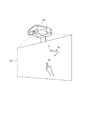
図1は、プロジェクター(位置検出装置)100の設置状態を示す図である。
プロジェクター100は、スクリーンSC(操作面)の直上又は斜め上方に設置され、斜め下方のスクリーンSCに向けて画像を投射する。スクリーンSCは、壁面に固定され、又は床面に立設された平板又は幕である。本発明は、この例に限定されず、壁面をスクリーンSCとして使用することも可能である。この場合、スクリーンSCとして使用される壁面の上部にプロジェクター100を取り付けるとよい。
FIG. 1 is a diagram illustrating an installation state of a projector (position detection device) 100.
The
プロジェクター100は、PC(パーソナルコンピューター)、ビデオ再生装置、DVD再生装置、Blu−ray(登録商標) Disc(ブルーレイディスク)再生装置等の画像供給装置に接続される。プロジェクター100は、画像供給装置から供給されるアナログ画像信号又はデジタル画像データに基づいて、スクリーンSCに画像を投射する。また、プロジェクター100は、内蔵する記憶部60(図2)や外部接続される記憶媒体に記憶された画像データを読み出して、この画像データに基づきスクリーンSCに画像を表示してもよい。
The
プロジェクター100は、スクリーンSCに対するユーザー(操作者)の指示操作を検出する。スクリーンSCに対する指示操作には、ペン型の指示体70、又はユーザーの手指である指示体80(対象物)が利用される。また、ユーザーの指示操作には、指示体70又は指示体80により、スクリーンSC上の位置を指定(指示)する操作、スクリーンSC上の位置を連続して指示する操作等が含まれる。スクリーンSC上の位置を連続して指示する操作とは、例えば、指示体70、80をスクリーンSCに対して動かし、文字や図形等を描く操作である。プロジェクター100は、指示されたスクリーンSCの位置を検出する検出処理を繰り返し行うことで、ユーザーがスクリーンSC上の位置を連続して指示する操作の指示位置の軌跡(動き)を検出できる。
The
指示体70の先端部71には、押圧された場合に動作する操作スイッチ75(図2)が内蔵される。指示体70の先端部71を壁やスクリーンSCに押しつける操作がされると、操作スイッチ75がオンになる。指示体70は、ユーザーが棒状の軸部72を手に持って、先端部71をスクリーンSCに接触させるように操作される。また、指示体70は、先端部71をスクリーンSCに押しつける操作も行われる。指示体70は、先端部71に、赤外光を発する送受信部74(図2)を備える。送受信部74は、操作スイッチ75がオンの場合と、オフの場合とで、赤外光の点灯パターンを変更する。
プロジェクター100は、指示体70が発する赤外光に基づき、先端部71の位置を、指示位置として検出する。また、プロジェクター100は、指示体70が発する赤外光の点灯パターンに基づいて、指示体70が壁やスクリーンSCに押しつけられているか否かを判定する。
An operation switch 75 (FIG. 2) that operates when pressed is built in the
The
また、プロジェクター100は、指示体80としてのユーザーの手指の指示位置を検出する。プロジェクター100は、指示体80による指示位置として、ユーザーの手指の位置と、手指がスクリーンSCに接触する接触位置とのいずれかを検出することができ、どちらを指示位置とするかを設定することもできる。また、プロジェクター100は、指示体80と、スクリーンSCとの距離を算出する。また、プロジェクター100は、ユーザーの複数本の指による指示操作が行われた場合に、これら複数本の指による指示位置を全て検出することも可能である。また、プロジェクター100は、複数本の指とスクリーンSCとの距離をそれぞれに算出することも可能である。
Further, the
プロジェクター100は、ユーザーが指示体70、80により行った指示操作を検出して、検出した指示操作をスクリーンSCの表示画像に反映させる。具体的には、プロジェクター100は、指示位置に図形を描画したり文字や記号を配置したりする処理、指示位置の軌跡に沿って図形を描画する処理、描画した図形や配置した文字又は記号を消去する処理等を行う。また、プロジェクター100は、スクリーンSCに描画された図形、配置された文字又は記号を画像データとして保存することもでき、外部の装置に出力することもできる。
さらに、プロジェクター100は、指示位置を検出することによりポインティングデバイスとして動作し、スクリーンSC上の指示位置の座標を出力してもよい。また、この座標を用いて、プロジェクター100に対してGUI(Graphical User Interface)操作を行うこともできる。
The
Further, the
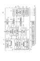
図2は、プロジェクター100の構成を示す構成図である。
プロジェクター100は、外部の装置に接続されるインターフェイスとして、I/F(インターフェイス)部11及び画像I/F(インターフェイス)部12を備える。I/F部11及び画像I/F部12は有線接続用のコネクターを備え、上記コネクターに対応するインターフェイス回路を備えていてもよい。また、I/F部11及び画像I/F部12は、無線通信インターフェイスを備えていてもよい。有線接続用のコネクター及びインターフェイス回路としては有線LAN、IEEE1394、USB等に準拠したものが挙げられる。また、無線通信インターフェイスとしては無線LANやBluetooth(登録商標)等に準拠したものが挙げられる。画像I/F部12には、HDMI(登録商標)インターフェイス等の画像データ用のインターフェイスを用いることもできる。画像I/F部12は、音声データが入力されるインターフェイスを備えてもよい。
FIG. 2 is a configuration diagram showing the configuration of the
The
I/F部11は、PC等の外部の装置との間で各種データを送受信するインターフェイスである。I/F部11は、画像の投射に関するデータ、プロジェクター100の動作を設定するデータ等を入出力する。後述する制御部30は、I/F部11を介して外部の装置とデータを送受信する機能を有する。
画像I/F部12は、デジタル画像データが入力されるインターフェイスである。本実施形態のプロジェクター100は、画像I/F部12を介して入力されるデジタル画像データに基づき画像を投射する。なお、プロジェクター100は、アナログ画像信号に基づき画像を投射する機能を備えていてもよく、この場合、画像I/F部12は、アナログ画像用のインターフェイスと、アナログ画像信号をデジタル画像データに変換するA/D変換回路とを備えてもよい。
The I /
The image I /
プロジェクター100は、光学的な画像の形成を行う投射部20を備える。投射部20は、光源部21、光変調装置22及び投射光学系23を有する。光源部21は、キセノンランプ、超高圧水銀ランプ、LED(Light Emitting Diode)又はレーザー光源等からなる光源を備える。また、光源部21は、光源が発した光を光変調装置22に導くリフレクター及び補助リフレクターを備えていてもよい。さらに、プロジェクター100は、投射光の光学特性を高めるためのレンズ群(図示略)、偏光板、又は光源が発した光の光量を光変調装置22に至る経路上で低減させる調光素子等を備えていてもよい。
The
光変調装置22は、例えばRGBの三原色に対応した3枚の透過型液晶パネルを備え、この液晶パネルを透過する光を変調して画像光を生成する。光源部21からの光はRGBの3色の色光に分離され、各色光は対応する各液晶パネルに入射する。各液晶パネルを通過して変調された色光はクロスダイクロイックプリズム等の合成光学系によって合成され、投射光学系23に射出される。
The
投射光学系23は、光変調装置22により変調された画像光をスクリーンSC方向へ導き、スクリーンSC上に結像させるレンズ群を備える。また、投射光学系23は、スクリーンSCの表示画像の拡大・縮小及び焦点の調整を行うズーム機構、フォーカスの調整を行うフォーカス調整機構を備えていてもよい。プロジェクター100が短焦点型である場合、投射光学系23に、画像光をスクリーンSCに向けて反射する凹面鏡を備えていてもよい。
The projection
投射部20は、制御部30の制御に従って光源部21を点灯させる光源駆動部45、及び制御部30の制御に従って光変調装置22を動作させる光変調装置駆動部46に接続される。光源駆動部45は、光源部21の点灯、消灯の切り替えを行い、光源部21の光量を調整する機能を有していてもよい。
The
プロジェクター100は、投射部20が投射する画像を処理する画像処理系を備える。この画像処理系は、プロジェクター100を制御する制御部30、記憶部60、操作検出部17、画像処理部40、光源駆動部45及び光変調装置駆動部46を含む。また、画像処理部40にはフレームメモリー41が接続され、制御部30には位置検出部50が接続される。これらの各部を画像処理系に含めてもよい。
The
制御部30は、所定の制御プログラム61を実行することによりプロジェクター100の各部を制御する。記憶部60は、制御部30が実行する制御プログラム61、及び制御部30が処理するデータを不揮発的に記憶する。記憶部60は、指示体70及び指示体80の少なくとも一方による指示位置の座標と、指示位置の軌跡を示す軌跡データと、タッチ情報と、距離情報とをユーザーの位置情報に対応づけて記憶する。なお、これらの情報の詳細については後述する。
The
画像処理部40は、制御部30の制御に従って、画像I/F部12を介して入力される画像データを処理し、光変調装置駆動部46に画像信号を出力する。画像処理部40が実行する処理は、3D(立体)画像と2D(平面)画像の判別処理、解像度変換処理、フレームレート変換処理、歪み補正処理、デジタルズーム処理、色調補正処理、輝度補正処理等である。画像処理部40は、制御部30により指定された処理を実行し、必要に応じて、制御部30から入力されるパラメーターを使用して処理を行う。また、上記のうち複数の処理を組み合わせて実行することも勿論可能である。
画像処理部40は、フレームメモリー41に接続されている。画像処理部40は、画像I/F部12から入力される画像データをフレームメモリー41に展開して、展開した画像データに対し上記の各種処理を実行する。画像処理部40は、処理後の画像データをフレームメモリー41から読み出して、この画像データに対応するR、G、Bの画像信号を生成し、光変調装置駆動部46に出力する。
光変調装置駆動部46は、光変調装置22の液晶パネルに接続される。光変調装置駆動部46は、画像処理部40から入力される画像信号に基づいて液晶パネルを駆動し、各液晶パネルに画像を描画する。
The
The
The light modulation
操作検出部17は、入力デバイスとして機能するリモコン受光部18及び操作パネル19に接続され、リモコン受光部18及び操作パネル19を介した操作を検出する。
リモコン受光部18は、プロジェクター100のユーザーが使用するリモコン(図示略)がボタン操作に対応して送信した赤外線信号を受光する。リモコン受光部18は、上記リモコンから受光した赤外線信号をデコードして、上記リモコンにおける操作内容を示す操作データを生成し、制御部30に出力する。
操作パネル19は、プロジェクター100の外装筐体に設けられ、各種スイッチ及びインジケーターランプを有する。操作検出部17は、制御部30の制御に従い、プロジェクター100の動作状態や設定状態に応じて操作パネル19のインジケーターランプを適宜点灯及び消灯させる。この操作パネル19のスイッチが操作されると、操作されたスイッチに対応する操作データが操作検出部17から制御部30に出力される。
The operation detection unit 17 is connected to a remote control
The remote control
The
位置検出部50は、スクリーンSCに対する指示体70、80の指示位置、又はスクリーンSCに対する指示体70、80の動きを検出する。位置検出部50は、撮影部51、撮影制御部52、送信部53及び検出部55の各部を備える。また、検出部55は、物体検出部551と、動き検出部552とを備える。
The
撮影部51は、指示体70、80の指示位置を検出するために、スクリーンSCとその周辺部とを含む範囲(操作面を含む範囲)を撮影範囲として撮影した撮影画像を形成する。
撮影部51は、赤外光による撮影と、可視光による撮影とを、それぞれ実行できる。具体的には、赤外光を撮影する赤外用撮像素子、可視光を撮影する可視光用撮像素子、赤外用撮像素子のインターフェイス回路、及び、可視光用撮像素子のインターフェイス回路を備えた構成とすることができる。また、1つの撮像素子により可視光と赤外光との撮影を行う構成であってもよい。また、例えば、撮影部51に、撮像素子に入射する光の一部を遮るフィルターを設け、撮像素子に赤外光を受光させる場合に、主に赤外領域の光を透過するフィルターを撮像素子の前に配置させてもよい。撮像素子は限定されず、CCD、CMOSのいずれであってもよいし、他の素子を用いてもよい。
In order to detect the pointing positions of the
The
撮影部51の赤外光による撮影時の撮影方向および撮影範囲(画角)は、投射光学系23と同じ方向、または略同じ方向を向き、投射光学系23がスクリーンSC上に画像を投射する範囲をカバーする。同様に、撮影部51の可視光による撮影時の撮影方向および撮影範囲は、投射光学系23と同じ方向、または略同じ方向を向き、投射光学系23がスクリーンSC上に画像を投射する範囲をカバーする。撮影部51は、赤外光で撮影した撮影画像のデータ、及び、可視光で撮影した撮影画像のデータを、それぞれ出力する。
The shooting direction and shooting range (view angle) at the time of shooting with infrared light of the
撮影制御部52は、制御部30の制御に従って撮影部51を制御し、撮影部51に撮影を実行させる。撮影制御部52は、撮影部51の撮影画像のデータを取得して、検出部55に出力する。また、撮影制御部52は、取得した撮影画像のデータを制御部30に出力する。制御部30は、撮影制御部52から入力される撮影画像のデータを記憶部60に記憶させる。
撮影部51が可視光で撮影した撮影画像には、スクリーンSC、スクリーンSCに投射された投射画像、及び、撮影範囲内に存在するユーザーが写る。また、撮影部51が赤外光で撮影する撮影画像には、指示体70が発する赤外光の像が写る。
The
The captured image captured by the capturing
送信部53は、撮影制御部52の制御に従って、指示体70に対して赤外線信号を送信する。送信部53は、赤外LED等の光源を有し、この光源を撮影制御部52の制御に従って点灯及び消灯させる。
The
物体検出部551は、撮影制御部52の撮影画像のデータから、人物が写った人物領域を検出する。人物領域は、撮影画像において人物の像を含む領域である。物体検出部551による人物領域の検出は、一般的に知られた方法を用いることができる。例えば、物体検出部551は、入力された撮影画像のデータのエッジを検出して、人の形状にマッチする領域を人物領域として検出する。また、物体検出部551は、色情報(輝度、色度等)が所定時間内に変化する領域を検出して、検出した領域のサイズが所定値以上のものや、検出した領域の経時的な移動範囲が所定範囲内のものを人物領域として検出してもよい。
物体検出部551は、人物領域を検出すると、検出した人物領域に基づいて、ユーザーの位置を特定する。例えば、物体検出部551は、撮影画像のデータの水平方向における、人物領域の中心座標をユーザーの位置を示す位置情報として算出する。物体検出部551は、撮影画像のデータから人物領域を複数検出した場合には、ユーザーの位置を示す位置情報も、人物領域に応じて複数検出する。
また、物体検出部551は、検出した人物領域に基づいて、ユーザーの身体の部位(例えば、頭部、肩、手、足等)を認識し、ユーザーの姿勢を検出する。ユーザーの姿勢とは、例えば、立位、座位、しゃがんだ状態、腕組みした状態などの体勢を指すが、スクリーンSC側を向いているかスクリーンと反対側を向いているか等の身体の向きを含んでもよい。物体検出部551は、検出したユーザーの姿勢に基づいて、ユーザーがスクリーンSCに対する指示操作を行い得る姿勢にあるか否かを判定する。物体検出部551は、例えば、ユーザーの姿勢が両腕を組んだ姿勢であると判定した場合、ユーザーがスクリーンSCに対する操作を行い得る姿勢にないと判定する。ユーザーがスクリーンSCに対する操作を行い得る姿勢にないと判定した場合、物体検出部551は、このユーザーが検出された人物領域に対する指示体80の検出等処理を中止してもよい。
The
When detecting the person area, the
In addition, the
また、物体検出部551は、撮影画像のデータの人物領域から、ユーザーの手指の画像を検出して指示体80を検出する。ユーザーの手指とは、1本または複数の指のみであってもよいし、手全体であってもよく、指を含む手の一部であってもよい。物体検出部551は、人物領域から、予め定めた手指の形状や特徴に近い領域を、指示体80の領域として検出する。
また、物体検出部551は、検出した指示体80が指し示すスクリーンSCの指示位置の座標を算出する。物体検出部551は、検出した指示体80の領域から手指の先端(指先)を特定し、特定した手指の先端の位置を指示位置として検出する。物体検出部551は、指示体80の指示位置の座標を、撮影画像のデータにおける座標で算出する。また、物体検出部551は、検出した指示位置の座標から、スクリーンSCの表示画像上に仮想的に設けられた座標軸における座標を算出する。撮影画像のデータにおける座標は、プロジェクター100とスクリーンSCとの距離、投射光学系23におけるズーム率、プロジェクター100の設置角度、撮影部51とスクリーンSCとの距離等の様々な要素の影響を受ける。物体検出部551は、事前に実施されるキャリブレーションの結果に基づき、撮影画像のデータにおける指示位置の座標から、スクリーンSCの表示画像における指示位置の座標を算出する。キャリブレーションでは、所定のパターン画像を投射部20からスクリーンSCに投射して、表示されたパターン画像を撮影部51で撮影する。撮影部51の撮影したパターン画像に基づいて、撮影画像のデータにおける座標と、スクリーンSCの表示画像上の座標との対応関係(座標変換パラメーター)が導かれる。
In addition, the
Further, the
また、物体検出部551は、検出した指示体80とスクリーンSCとの距離を検出する。物体検出部551は、検出した手指の先端と、スクリーンSCとの距離を撮影画像のデータに基づいて判定する。例えば、物体検出部551は、撮影画像のデータから指の画像と、指の影の画像とを検出して、検出した画像の間の距離に基づいて、手指の先端とスクリーンSCとの距離を求める。
また、物体検出部551は、撮影画像のデータから複数の人物領域を検出した場合には、各人物領域について、指示体80と、指示体80の指示位置の座標とを検出し、検出した指示体80とスクリーンSCとの距離を算出する。
Further, the
Further, when detecting a plurality of person regions from the captured image data, the
物体検出部551は、指示体80の指示位置の座標と、指示体80とスクリーンSCとの距離を示す距離情報とを、該当のユーザーの位置情報と共に制御部30に出力する。制御部30は、指示位置の座標と、距離情報とをユーザーの位置情報に対応付けて記憶部60に記憶させる。
The
また、物体検出部551は、指示体70の指示位置の座標を検出する。物体検出部551は、撮影部51が赤外光で撮影した撮影画像のデータに写った赤外光の像を検出して、指示体70の指示位置の座標を検出する。撮影部51の撮影画像のデータから指示体70を特定する方法の詳細については後述する。
物体検出部551は、指示体70の指示位置の座標を検出すると、キャリブレーションの結果に基づいて、撮影画像のデータにおける指示位置の座標から、スクリーンSCの表示画像における指示位置の座標を算出する。また、物体検出部551は、指示体70の先端がスクリーンSCに接しているか否かを判定する。指示体70の先端がスクリーンSCに接しているか否かの判定方法についても後述する。
The
When detecting the coordinates of the designated position of the
また、物体検出部551は、検出した指示体70の指示位置の座標に基づいて、指示体70を対応付けるユーザーを特定する。すなわち、物体検出部551は、指示体70を手に持って操作しているユーザーを特定する。撮影画像のデータから複数の人物領域が検出される場合、複数のユーザーが指示体70を使用している場合もある。このため、物体検出部551は、検出した人物領域と、指示体70の指示位置の座標(撮影画像のデータにおける座標)とに基づいて、指示体70とユーザーの位置情報とを対応付ける。物体検出部551は、指示体70の指示位置の座標が、どの人物領域に含まれるか、又はどの人物領域に最も近いかによって指示体70とユーザーの位置情報とを対応付ける。
物体検出部551は、指示体70とユーザーの位置情報とを対応付けると、指示体70の指示位置の座標と、タッチ情報とを、対応付けたユーザーの位置情報と共に制御部30に出力する。タッチ情報とは、指示体70がスクリーンSCに接触しているか否かを示す情報である。
In addition, the
When the
動き検出部552は、制御部30によって指示された指示体70、80の動きを検出する。動き検出部552は、不図示のメモリーを備え、物体検出部551により検出される、指示体70、80の指示位置の座標をメモリーに一時的に記憶して、指示体70、80のスクリーンSCに対する相対位置の経時変化を求める。動き検出部552は、メモリーに記憶させた指示体70、80の指示位置の座標に基づいて、各指示体70、80の指示位置の動きを表す軌跡データを作成する。動き検出部552は、作成した指示体70、80の指示位置の軌跡データを、制御部30に出力する。
制御部30は、動き検出部552から入力される指示体70、80の指示位置の軌跡データを、該当するユーザーの位置情報に対応付けて記憶部60に記憶させる。また、制御部30は、指示体70、80の指示位置の軌跡データに基づいて、指示体70、80による指示操作を検出する。
The
The
指示体70は、制御部73、送受信部74、操作スイッチ75及び電源部76を備え、これらの各部は軸部72(図1)に収容される。制御部73は、送受信部74及び操作スイッチ75に接続され、操作スイッチ75のオン/オフ状態を検出する。送受信部74は、赤外LED等の光源と、赤外光を受光する受光素子とを備え、制御部73の制御に従って光源を点灯及び消灯させるとともに、受光素子の受光状態を示す信号を制御部73に出力する。
電源部76は、電源として乾電池又は二次電池を有し、制御部73、送受信部74及び操作スイッチ75の各部に電力を供給する。指示体70は、電源部76からの電源供給をオン/オフする電源スイッチを備えていてもよい。
The
The
ここで、位置検出部50と指示体70との相互の通信により、撮影部51の撮影画像のデータから指示体70の指示位置を特定する方法について説明する。
制御部30は、指示体70による操作を検出する場合に、撮影制御部52を制御して、送信部53から同期用の信号を送信させる。すなわち、撮影制御部52は、制御部30の制御に従って、送信部53の光源を所定の周期で点灯させる。送信部53が周期的に発する赤外光が、位置検出部50と指示体70とを同期させる同期信号として機能する。
一方、制御部73は、電源部76から電源の供給が開始され、所定の初期化動作を行った後、プロジェクター100の送信部53が発する赤外光を、送受信部74により受光する。送信部53が周期的に発する赤外光を送受信部74により受光すると、制御部73は、この赤外光のタイミングに同期させて、予め設定された指示体70に固有の点灯パターンで、送受信部74の光源を点灯(発光)させる。また、制御部73は、操作スイッチ75の操作状態に応じて、送受信部74の点灯パターンを切り替える。このため、プロジェクター100の物体検出部551は、複数の撮影画像のデータに基づいて、指示体70の操作状態、すなわち先端部71がスクリーンSCに押しつけられているか否かを判定できる。
また、制御部73は、電源部76から電源が供給されている間、上記のパターンを繰り返し実行する。つまり、送信部53は、指示体70に対し、同期用の赤外線信号を周期的に送信し、指示体70は、送信部53が送信する赤外線信号に同期して、予め設定された赤外線信号を送信する。
Here, a method for specifying the indicated position of the
When detecting an operation by the
On the other hand, after the supply of power from the
The
位置検出部50の撮影制御部52は、撮影部51による撮影タイミングを、指示体70が点灯するタイミングに合わせる制御を行う。この撮影タイミングは、撮影制御部52が送信部53を点灯させるタイミングに基づいて決定される。物体検出部551は、撮影部51の撮影画像のデータに指示体70の光の像が写っているか否かにより、指示体70が点灯するパターンを特定できる。物体検出部551は、複数の撮影画像のデータに基づいて、指示体70の先端部71がスクリーンSCに押しつけられているか否かを判定して、タッチ情報を生成する。
指示体70の点灯パターンは、指示体70の個体毎に固有のパターン、又は複数の指示体70に共通のパターンと個体毎に固有のパターンとを含むものとすることができる。この場合、撮影制御部52は、撮影画像のデータに複数の指示体70が発する赤外光の像が含まれる場合に、各々の像を、異なる指示体70の像として区別できる。
The
The lighting pattern of the
制御部30は、記憶部60に記憶された制御プログラム61を読み出して実行することにより投射制御部31、判定部32及び検出制御部33の機能を実現し、プロジェクター100の各部を制御する。
The
投射制御部31は、操作検出部17から入力される操作データに基づいて、ユーザーがリモコンを操作して行った操作内容を取得する。投射制御部31は、ユーザーが行った操作に応じて画像処理部40、光源駆動部45及び光変調装置駆動部46を制御して、スクリーンSCに画像を投射させる。
また、投射制御部31は、画像処理部40を制御して、上述した3D(立体)画像と2D(平面)画像の判別処理、解像度変換処理、フレームレート変換処理、歪み補正処理、デジタルズーム処理、色調補正処理、輝度補正処理等を実行させる。また、投射制御部31は、画像処理部40の処理に合わせて光源駆動部45を制御し、光源部21の光量を制御する。
Based on the operation data input from the operation detection unit 17, the
Further, the
判定部32は、物体検出部551から、指示体80の指示位置の座標及び距離情報と、指示体70の指示位置の座標及び距離情報とを入力する。
判定部32は、入力された指示体70のスクリーンSCとの距離と、指示体80のスクリーンSCとの距離とを比較して、指示体70の指示位置又は動きを、指示操作として検出するか否かを判定する。判定部32は、指示体70とスクリーンSCとの距離が、指示体80とスクリーンSCとの距離よりも離れている場合に、指示体70を、指示操作の検出対象から除外する。すなわち、判定部32は、指示体70、80のうちスクリーンSCにより近い側を、スクリーンSCに対する指示操作の検出候補として選択する。
また、判定部32は、指示操作の検出候補として選択した指示体80であって、指示体80とスクリーンSCとの距離が所定距離以内である場合に、この指示体80を、指示操作を検出する指示体として選択する。物体検出部551により検出された指示体であっても、スクリーンSCとの距離が所定距離以内にない指示体の指示操作は検出しないようにする。
なお、指示体70、80がスクリーンSCに接しているか否かを判定して、スクリーンSCに対する指示操作を検出する指示体を選択するものであってもよい。例えば、判定部32は、指示体80がスクリーンSCに接し、指示体70がスクリーンSCに接していないと判定する場合、指示体80は、指示体70よりもスクリーンSCに近い位置にあると判定できる。また、指示体80はスクリーンSCに接しているため、判定部32は、スクリーンSCとの距離が所定距離以内にあると判定できる。
The
Whether the
Further, the
Note that it may be determined whether or not the
判定部32は、選択した指示体80の動きを、動き検出部552に検出させる。判定部32は、選択した指示体80のスクリーンSCに対する動きを示す軌跡データを動き検出部552から入力し、入力した軌跡データに基づいて指示体80の指示操作を検出する。指示操作には、上述したように、指示体80によるスクリーンSCの位置を指示する操作や、指示体80のスクリーンSCに対する動きが含まれる。
判定部32は、スクリーンSCに対する指示体80の動きと、スクリーンSCに対する指示体70の位置とを検出することにより、指示体70を、指示操作の検出対象とするか否かを判定する。判定部32により、指示体70とスクリーンSCとの距離が、スクリーンSCと指示体80との距離よりも離れると判定される場合、「スクリーンSCに対する指示体70の位置」の条件が満たされる。
また、指示体80の軌跡データに基づいて、指示体80がスクリーンSCの一定位置(指示位置)から所定時間動かないと判定部32により判定される場合、「スクリーンSCに対する指示体80の動き」の条件が満たされる。例えば、図3に示すように、指示体70を把持した手の指でスクリーンSCをタッチしている場合、指示体80としての手の指が、指示体70よりもスクリーンSCに近い。この場合、判定部32は、指示体80がスクリーンSCの一定位置から所定時間以上動かなければ、軌跡データに基づく指示体80の動きを、スクリーンSCに対する位置の指示操作と判定する。この場合、判定部32は、例えば、指示体80により指示された指示位置の座標に、指示体80による指示であることを示す識別データと、描画した図形や配置した文字又は記号を消去する消去コマンドとを付加して検出制御部33に出力する。
The
The
Further, when the
また、同一の人物領域から、複数の指示体80が検出される場合、判定部32は、これらの複数の指示体80の動きを動き検出部552に検出させる。
判定部32は、動き検出部552により検出される、複数の指示体80それぞれの軌跡データに基づいて、指示体80間の距離の変化を判定する。例えば、図4に示すように指示体80間の距離が時間経過とともに広がる場合、判定部32は、これらの指示体80の動きは、スクリーンSCに対する指示操作であると判定する。この場合、判定部32は、これらの指示体80の動きを、スクリーンSCに表示される表示画像を拡大させる指示操作と判定する。この場合、判定部32は、表示画像を拡大させる指示コマンドと、各指示体80の軌跡データから求めた表示画像の拡大率と、指示体80による指示であることを示す識別データを検出制御部33に出力する。
また、図4とは逆に、指示体80間の距離が時間経過とともに狭くなる場合にも、判定部32は、複数の指示体80の動きを、スクリーンSCに対する指示操作であると判定する。この場合、判定部32は、これらの指示体80の動きを、表示画像を縮小させる指示操作であると判定する。この場合、判定部32は、表示画像を縮小させる指示コマンドと、各指示体80の軌跡データから求めた表示画像の縮小率と、指示体80による指示であることを示す識別データとを検出制御部33に出力する。
When a plurality of
The
In contrast to FIG. 4, also when the distance between the
また、判定部32は、物体検出部551により複数のユーザーの手指が指示体80として検出された場合、まず、検出された指示体80と、ユーザーとを対応付ける。すなわち、1人のユーザーから複数の指示体80が検出される場合もあるため、判定部32は、スクリーンSCと各指示体80との距離に基づいて、ユーザーごとに、指示操作を検出する指示体80を1つ選択する。そして、判定部32は、検出された各指示体80の動きが、指示操作に該当するか否かをユーザーごとに判定する。判定部32は、動き検出部552から入力される各指示体80の軌跡データに基づいて、指示操作をそれぞれに検出する。
Further, when a plurality of user's fingers are detected as the
検出制御部33は、位置検出部50を制御して、指示体70、80の検出を実行させる。
また、検出制御部33は、判定部32から、判定部32が検出した指示体70又は80の指示操作に応じたデータを取得する。例えば、判定部32が検出した指示操作が、スクリーンSCに描画された文字を消去する指示である場合、検出制御部33は、判定部32から、指示体80による指示位置の座標と、指示体80の指示であることを示す識別データと、消去コマンドとを入力する。検出制御部33は、判定部32から取得したデータに従い、描画された文字を消去する指示を画像処理部40に通知する。画像処理部40は、検出制御部33の指示に従って、フレームメモリー41に展開された画像データの該当の指示位置に重畳された文字を消去する。
The
Further, the
また、判定部32が検出した指示操作が、表示画像を拡大させる指示である場合、検出制御部33は、判定部32から、表示画像を拡大させる指示コマンドと、表示画像の拡大率と、指示体80の指示であることを示す識別データとを入力する。
検出制御部33は、判定部32の指示に従い、画像処理部40に、表示画像の拡大を指示する。画像処理部40は、フレームメモリー41に展開された画像データを、検出制御部33から指示された拡大率で拡大処理し、処理した画像データに基づく画像信号を光変調装置駆動部46に出力する。
When the instruction operation detected by the
The
また、検出制御部33は、判定部32から、指示体70又は80の指示操作に応じたコマンドと、指示位置の座標又は指示位置の軌跡データと、指示体70による指示であるのか指示体80による指示であるのかを示す識別データとを入力する。この他に、検出制御部33は、指示体70による指示である場合に、タッチ情報や距離情報を判定部32から入力し、指示体80による指示である場合に、距離情報を判定部32から入力する。
検出制御部33は、判定部32から、例えば、図形描画のコマンドを入力した場合、判定部32から取得した指示位置の座標又は指示位置の軌跡に基づいて画像処理部40に図形を描画させる。また、検出制御部33は、画像処理部40に、描画した図形を画像I/F部12に入力される入力画像に重畳して投射させる処理を行う。
また、検出制御部33は、判定部32から入力されるコマンドに応じて、取得した指示位置の座標又は指示位置の軌跡データをI/F部11に接続されたPC等の外部の装置に出力してもよい。この場合、検出制御部33は、取得した指示位置の座標又は指示位置の軌跡を、I/F部11に接続された外部の装置のオペレーティングシステムにおいて、座標入力デバイスの入力として認識されるデータフォーマットに変換して出力してもよい。例えば、I/F部11にWindows(登録商標)オペレーティングシステムで動作するPCが接続された場合、オペレーティングシステムにおいてHID(Human Interface Device)の入力データとして処理されるデータを出力する。また、検出制御部33は、指示位置の座標又は指示位置の軌跡データとともに、これらのデータが指示体70の操作によるものであるか指示体80の操作によるものであるのかを識別するデータ、及びタッチ情報や距離情報を外部の装置に出力してもよい。
Further, the
For example, when a graphic drawing command is input from the
Further, the
図5及び図6は、プロジェクター100の処理手順を示すフローチャートである。
まず、位置検出部50の検出部55は、撮影部51により撮影された撮影画像のデータを撮影制御部52から入力する(ステップS1)。制御部30の検出制御部33は、撮影制御部52を制御して、撮影部51に撮影範囲を撮影させる。撮影部51は、赤外光による撮影と可視光による撮影とを交互に実行する。撮影制御部52は、撮影部51により撮影された撮影画像のデータを位置検出部50に出力する。
5 and 6 are flowcharts showing the processing procedure of the
First, the
位置検出部50の物体検出部551は、入力された撮影画像のデータから人物が写った人物領域を検出する(ステップS2)。物体検出部551は、撮影画像のデータから人物領域を検出することができなかった場合(ステップS2/NO)、ステップS7の処理に移行する(ステップS7)。また、物体検出部551は、撮影画像のデータから人物領域を検出した場合(ステップS2/YES)、検出した人物領域ごとに、ユーザーの位置、姿勢を検出する(ステップS3)。物体検出部551は、例えば、撮影画像のデータの水平方向における、人物領域の中心座標値をユーザーの位置を示す位置情報として算出する。また、物体検出部551は、撮影画像のデータから人物領域を複数検出した場合には、ユーザーの位置を示す位置情報も、人物領域に応じて複数検出する。また、物体検出部551は、検出した人物領域に基づいて、ユーザーの頭部、肩、手、足等の人体の部位を認識し、ユーザーの姿勢を検出する(ステップS3)。
The
物体検出部551は、検出したユーザーの位置、姿勢に基づいて、ユーザーが、スクリーンSCに対する操作を行い得る位置、姿勢にあるか否かを判定する(ステップS4)。例えば、ユーザーとスクリーンSCとの距離が離れている場合や、ユーザーが両腕を組んでいる場合には、物体検出部551は、ユーザーがスクリーンSCに対する指示操作を行い得る姿勢にないと判定する。
ステップS4が否定判定の場合(ステップS4/NO)、物体検出部551は、該当ユーザーの人物領域に対する処理を中止し、ステップS2において他の人物領域を検出しているか否かを判定する(ステップS5)。肯定判定の場合(ステップS5/YES)、物体検出部551は、他の人物領域に対してステップS3及び4の処理を行う。また、否定判定の場合(ステップS5/NO)、ステップS1に戻り、検出部55は、撮影部51により撮影された撮影画像のデータを撮影制御部52から入力する(ステップS1)。
Based on the detected position and orientation of the user, the
If step S4 is negative (step S4 / NO), the
また、ステップS4が肯定判定の場合(ステップS4/YES)、物体検出部551は、撮影画像のデータの人物領域から、ユーザーの手指の画像を検出して指示体80を検出する。物体検出部551は、人物領域から、予め定めた手指の形状や特徴に近い領域を、指示体80の領域として検出する。また、物体検出部551は、検出した指示体80の領域から指示体80が指し示すスクリーンSCの指示位置の座標を算出する(ステップS6)。物体検出部551は、検出した指示体80の領域から手指の先端(指先)を特定して、特定した手指の先端の位置を指示位置の座標として検出する。また、物体検出部551は、検出した指示体80の指示位置の座標を、スクリーンSCの表示画像における指示位置の座標に変換する。また、物体検出部551は、指示体80とスクリーンSCとの距離とを検出する。物体検出部551は、座標変換した指示体80の指示位置の座標と、指示体80とスクリーンSCとの距離情報とを、該当するユーザーの位置情報と共に制御部30に出力する。制御部30は、物体検出部551から指示体80の指示位置の座標と、距離情報と、ユーザーの位置情報とが入力されると、入力された指示体80の指示位置の座標と、距離情報とを該当のユーザーの位置情報に対応付けて記憶部60に記憶させる。
When step S4 is affirmative (step S4 / YES), the
次に、物体検出部551は、赤外光によって撮影された撮影画像のデータに、指示体70の発する赤外光が写っているか否かを判定して指示体70を検出する(ステップS7)。物体検出部551は、撮影画像のデータに、指示体70の発する赤外光を検出した場合、検出した赤外光の撮影画像のデータにおける位置を、指示体70の指示位置の座標として検出する(ステップS8)。また、物体検出部551は、指示体70の先端部71がスクリーンSCに押しつけられているか否かを判定する。指示体70の制御部73は、操作スイッチ75の操作状態に応じて送受信部74の点灯パターンを切り替える。物体検出部551は、撮影部51の複数の撮影画像のデータに基づいて送受信部74の点灯パターンを判定し、指示体70の先端部71がスクリーンSCに押しつけられているか否かを判定する。また、物体検出部551は、撮影部51の可視光によって撮影された撮影画像のデータに基づいて、指示体70とスクリーンSCとの距離を算出する。物体検出部551は、例えば、撮影画像のデータから指示体70の画像と、指示体70の影の画像とを検出して、検出した画像の間の距離に基づいて、指示体70の先端とスクリーンSCとの距離を求める。
物体検出部551は、指示体70の指示位置の座標と、タッチ情報と、距離情報とを、該当するユーザーの位置情報と共に制御部30に出力する。制御部30は、物体検出部551から入力される指示体70の指示位置の座標と、タッチ情報と、距離情報とを該当のユーザーの位置情報に対応付けて記憶部60に記憶させる。
Next, the
The
次に、判定部32は、動き検出部552に、指示体80の動きを示す軌跡データを生成させ、動き検出部552から取得した指示体80の軌跡データと、指示体70の指示位置の座標とに基づいて、指示体70を無効にするか否かを判定する(ステップS9)。この処理の詳細は、図6に示す。判定部32は、指示体70を無効にすると判定すると(ステップS10/YES)、指示体70に関するデータ、例えば、指示体70の指示位置の座標を無効にして、検出制御部33には出力しない。この場合、判定部32は、指示体80の軌跡データや、指示体80の指示位置の座標から検出した指示操作に応じたデータを検出制御部33に出力する。検出制御部33は、取得した座標及びデータに基づいて、予め設定された処理を実行する(ステップS11)。例えば、判定部32から、指示位置の座標と、指示体80による指示であることを示す識別データと、消去コマンドとが入力されると、検出制御部33は、指示された位置に描画された図形や配置した文字又は記号を消去する指示を画像処理部40に通知する。画像処理部40は、検出制御部33から通知された指示に従い、フレームメモリー41に展開された画像データの該当位置に重畳された図形、文字又は記号を消去する。
また、検出制御部33は、判定部32から、画像を拡大させる指示コマンドと、各指示体80の軌跡データから求めた表示画像の拡大率と、指示体80による指示であることを示す識別データとが入力された場合、画像処理部40に、表示画像の拡大を指示する。画像処理部40は、フレームメモリー41に展開された画像データを、検出制御部33から指示された拡大率で拡大処理し、処理した画像データに基づく画像信号を光変調装置駆動部46に出力する。
Next, the
Further, the
また、ステップS10において、指示体70を無効にしないと判定すると(ステップS10/NO)、判定部32は、動き検出部552に、指示体70の動きを検出するように、指示する。判定部32は、動き検出部552から入力される指示体70の動きを表す軌跡データに基づいて、指示体70による指示操作を検出する。そして、判定部32は、検出した指示操作に応じたデータを検出制御部33に出力する。検出制御部33は、判定部32から取得したデータに基づいて、予め設定された処理を実行する(ステップS12)。例えば、検出制御部33は、判定部32から取得した指示位置の座標又は指示位置の軌跡に基づいて画像処理部40に図形を描画させ、描画した図形を画像I/F部12に入力される入力画像に重畳して投射させる処理を行う。
If it is determined in step S10 that the
次に、判定部32は、すべてのユーザーの指示操作を検出したか否かを判定する(ステップS13)。ステップS6において検出した指示体80の指示位置の座標や、ステップS8で検出した指示体70の指示位置の座標は、ユーザーの位置情報に対応付けられて、記憶部60に記憶される。判定部32は、記憶部60に位置情報を記憶したすべてのユーザーについて、ステップS9〜S12の処理を実行済みであるか否かを判定する。否定判定の場合(ステップS13/NO)、判定部32は、ステップS9からの処理を実行する。また、肯定判定の場合(ステップS13/YES)、ステップS1に戻り、検出部55は、撮影画像のデータを撮影制御部52から入力する。
Next, the
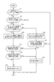
図6は、図5のステップS9の詳細を示すフローチャートである。
まず、判定部32は、指示体70を検出した場合に、検出した指示体70がスクリーンSCに接しているか否かを判定する(ステップS21)。判定部32は、タッチ情報に基づいて、指示体70がスクリーンSCに接しているか否かを判定する。肯定判定の場合(ステップS21/YES)、判定部32は、指示体70を無効にはしないと判定して(ステップS29)、この処理フローを終了させる。この後、判定部32は、動き検出部552に、指示体70の動きを検出させ、動き検出部552から入力される指示体70の軌跡データに基づいて、指示体70による指示操作を検出する。
FIG. 6 is a flowchart showing details of step S9 in FIG.
First, the
また、ステップS21が否定判定の場合(ステップS21/NO)、判定部32は、指示体80を検出している場合に、検出した指示体80がスクリーンSCに接しているか否かを判定する(ステップS22)。判定部32は、物体検出部551が検出した指示体80とスクリーンSCとの距離情報に基づいて、指示体80がスクリーンSCに接しているか否かを判定する。否定判定の場合(ステップS22/NO)、指示体70及び80がスクリーンSCに接していないので、図5に示すS13に進み、他のユーザーの指示操作を検出したか否かを判定する(ステップS13)。
また、肯定判定の場合(ステップS22/YES)、判定部32は、指示体80とスクリーンSCとの距離が、指示体70とスクリーンSCとの距離よりも近いと判定する。また、判定部32は、指示体80がスクリーンSCに接しているため、指示体80とスクリーンSCとの距離が所定距離以内であると判定する。このため、判定部32は、指示体80を、指示操作を検出する指示体として選択する。
次に、判定部32は、同一ユーザーの複数の指示体80がスクリーンSCに接しているか否かを判定する(ステップS23)。判定部32は、ユーザーの位置情報に、複数の指示体80の指示位置が対応付けられているか否かを判定する。同一ユーザーの位置情報に、複数の指示体80の指示位置が対応付けられている場合、判定部32は、対応付けられた他の指示体80がスクリーンSCに接しているか否かを判定する(ステップS23)。
When step S21 is negative (step S21 / NO), the
When the determination is affirmative (step S22 / YES), the
Next, the
ステップS23が否定判定の場合(ステップS23/NO)、判定部32は、スクリーンSCに接した指示体80の動きを、動き検出部552に検出させる(ステップS24)。その後、判定部32は、動き検出部552から入力される指示体80の軌跡データに基づいて、指示体80による指示操作を検出したか否かを判定する(ステップS25)。例えば、図3に示すように、指示体70を把持した手の指でスクリーンSCをタッチしている場合、指示体80としての手の指が、指示体70よりもスクリーンSCに近い。この場合、判定部32は、指示体80がスクリーンSCの一定位置から所定時間以上動かなければ、軌跡データに基づく指示体80の動きを、スクリーンSCに対する位置の指示操作と判定する。ステップS25が肯定判定の場合(ステップS25/YES)、判定部32は、指示体70を無効にする(ステップS30)。すなわち、判定部32は、指示体70に関するデータ、例えば、指示体70の指示位置の座標を無効にして、検出制御部33には出力しないようにする。また、判定部32は、例えば、指示体80により指示された指示位置の座標に、指示体80による指示であることを示す識別データと、消去コマンドとを付加して検出制御部33に出力する。
なお、指示体80は、指示体70を把持した手とは反対側の手であってもよい。例えば、右手で指示体70を把持している場合に、指示体80としての左手の動きを動き検出部552により検出するものであってもよい。
また、ステップS25が否定判定の場合(ステップS25/NO)、判定部32は、指示体70を無効にせずに(ステップS29)、動き検出部552に、指示体70の動きを検出させる。判定部32は、動き検出部552から入力される指示体70の軌跡データに基づいて、指示体70による指示操作を検出する。
When step S23 is negative determination (step S23 / NO), the
The
If step S25 is negative (step S25 / NO), the
また、ステップS23が肯定判定の場合(ステップS23/YES)、判定部32は、動き検出部552に、スクリーンSCに接した複数の指示体80の動きを検出させる(ステップS26)。その後、判定部32は、動き検出部552から入力される複数の指示体80の軌跡データに基づいて、複数の指示体80による指示操作を検出したか否かを判定する(ステップS27)。まず、判定部32は、複数の手指の軌跡データに基づいて、指示体80としての手指の間隔を広げる動きを検出したか否かを判定する(ステップS27)。判定部32は、例えば、左手と右手の間隔を広げる動きや、同じ手の指の間隔を広げる動きを検出したか否かを判定する。肯定判定の場合(ステップS27/YES)、判定部32は、指示体80の指示操作を検出したため、指示体70を無効にすると判定する(ステップS30)。すなわち、判定部32は、指示体70に関するデータ、例えば、指示体70の指示位置の座標を無効にして、検出制御部33には出力しないようにする。
また、否定判定の場合(ステップS27/NO)、判定部32は、複数の手指の軌跡データに基づいて、指示体80としての手指の間隔を狭める動きを検出したか否かを判定する(ステップS28)。判定部32は、例えば、左手と右手の間隔を狭める動きや、同じ手の指の間隔を狭める動きを検出したか否かを判定する。肯定判定の場合(ステップS28/YES)、判定部32は、指示体80の指示操作を検出したため、指示体70を無効にすると判定する(ステップS30)。また、否定判定の場合(ステップS28/NO)、判定部32は、指示体70を無効にはしないと判定し(ステップS29)、この処理フローを終了する。この後、判定部32は、動き検出部552に、指示体70の動きを検出させる。判定部32は、動き検出部552から入力される指示体70の軌跡データに基づいて、指示体70による指示操作を検出する。
If step S23 is affirmative (step S23 / YES), the
In the case of negative determination (step S27 / NO), the
なお、図6に示すフローチャートでは、プロジェクター100は、指示体70又は80がスクリーンSCに接している場合に、動き検出部552に、指示体80のスクリーンSCに対する動きを検出させるとして説明した。これ以外に、指示体80がスクリーンSCに接していなくても、指示体80とスクリーンSCとの距離が近接している場合に、動き検出部552に、指示体80の動きを検出させ、検出した指示体80の動きから指示操作を検出するものであってもよい。
In the flowchart shown in FIG. 6, the
以上説明したように、本実施形態のプロジェクター100は、検出部55と、撮影部51と、制御部30とを備える。検出部55は、スクリーンSCに対して操作を行う指示体70、及び指示体70とは異なる指示体80を検出する。撮影部51は、スクリーンSCを含む範囲を撮影した撮影画像を形成する。制御部30は、判定部32により、撮影画像のデータに基づいて、スクリーンSCに対する指示体80の動きと、スクリーンSCに対する指示体70の位置を検出することにより、指示体70による操作を入力として検出するか否かを判定する。従って、ユーザーの意図しない操作を入力として検出しないようにすることができる。
As described above, the
また、検出部55は、指示体70の位置又は動きを検出し、制御部30は、指示体80の位置又は動きに基づき入力を検出する。従って、制御部30の判定結果に応じて、検出部55に、指示体70又は指示体80の位置又は動きを操作として検出させることができる。
The
また、制御部30は、指示体70とスクリーンSCとの距離、及び、指示体80とスクリーンSCとの距離に基づいて、指示体70の位置又は動きを入力として検出するか否かを判定する。従って、指示体70及び指示体80のスクリーンSCとの距離を変更することで、指示体70の位置又は動きを検出するのか、指示体80の位置又は動きを検出するのかを切り替えることができる。
Further, the
また、制御部30は、指示体70とスクリーンSCとの距離が、指示体80とスクリーンSCとの距離よりも離れている場合に、指示体70の位置又は動きを入力として検出しない。従って、指示体70のスクリーンSCとの距離を、指示体80とスクリーンSCとの距離よりも離れている場合に、指示体70の位置又は動きを入力として検出しないようにすることができる。
In addition, when the distance between the
また、制御部30は、検出部55が複数の指示体80を検出した場合に、スクリーンSCとの距離が、指示体70とスクリーンSCとの距離よりも近い指示体80の位置又は動きを入力として検出する。従って、スクリーンSCとの距離が、指示体70とスクリーンSCとの距離よりも近い複数の指示体80の位置又は動きを操作として検出することができる。
In addition, when the
また、制御部30は、スクリーンSCとの距離が、指示体70とスクリーンSCとの距離よりも近い指示体80が複数検出された場合に、これら複数の指示体80の間の距離の変化を、撮影部51の撮影画像のデータに基づいて求める。制御部30は、求めた距離の変化に基づいてスクリーンSCに対する指示体80の動きを入力として検出する。従って、複数の指示体80間の距離の変化を、スクリーンSCに対する指示体80の動きとして検出することができる。
In addition, when a plurality of
また、制御部30は、撮影部51の撮影画像のデータに基づいて、それぞれの指示体80のスクリーンSCに対する相対位置の経時変化を求めることにより、複数の指示体80の間の距離の変化を検出する。従って、複数の指示体80それぞれのスクリーンSCに対する相対位置の経時変化を求めて、複数の指示体80間の距離の変化を検出することができる。
In addition, the
また、制御部30は、検出部55が検出する指示体80が、指示体70を把持したユーザーの手指である場合に、指示体80の位置又は動きを入力として検出する。従って、指示体70を把持したままのユーザーの手指によって操作することが可能となる。
Further, the
また、制御部30は、検出部55が複数の指示体80を検出した場合に、検出した複数の指示体80それぞれをユーザーに対応付けて、指示体80による操作をユーザーごとに検出部55に検出させる。従って、指示体80による操作をユーザーごとに検出することができる。
In addition, when the
なお、上述した実施形態及び変形例は本発明を適用した具体的態様の例に過ぎず、本発明を限定するものではなく、異なる態様として本発明を適用することも可能である。例えば、指示体70、80は、ペン型の指示体70やユーザーの手指である指示体80に限定されず、レーザーポインターや指示棒等を用いてもよく、その形状やサイズは限定されない。
Note that the above-described embodiments and modifications are merely examples of specific modes to which the present invention is applied, and the present invention is not limited thereto, and the present invention can be applied as different modes. For example, the
また、上記実施形態では、位置検出部50は、撮影部51によりスクリーンSCを撮影して指示体70の位置を特定するものとしたが、本発明はこれに限定されない。例えば、撮影部51は、プロジェクター100の本体に設けられ、投射光学系23の投射方向を撮影するものに限定されない。撮影部51をプロジェクター100本体とは別体として位置検出装置を構成し、撮影部51がスクリーンSCの側方や正面から撮影を行うものとしてもよい。さらに、複数の撮影部51を配置し、これら複数の撮影部51の撮影画像のデータに基づいて、検出部55が指示体70、80の位置を検出してもよい。さらに、位置検出部50と、制御部30の判定部32及び検出制御部33の機能を、プロジェクターとは独立した位置検出装置として実現することもできる。また、プロジェクター以外の表示装置に、位置検出部50と、制御部30の判定部32及び検出制御部33の機能を持たせて、位置検出装置として動作させる態様も実現可能である。
In the above embodiment, the
また、上記実施形態では、プロジェクター100から指示体70に対し、送信部53が発する赤外線信号を用いて指示体70に同期用の信号を送信する構成を説明したが、同期用の信号は赤外線信号に限定されない。例えば、電波通信や超音波無線通信により同期用の信号を送信する構成としてもよい。この構成は、電波通信や超音波無線通信により信号を送信する送信部53をプロジェクター100に設け、同様の受信部を指示体70に設けることで実現できる。
In the above-described embodiment, the configuration in which the
また、上述した実施形態では、指示体70の先端部71がスクリーンSCに押しつけられているか否かを、送受信部74の点灯パターンに基づいて判定する例を説明したが、本発明はこれに限定されない。例えば、指示体70の先端部71がスクリーンSCに押しつけられているか否かを、指示体80と同様に、撮影画像のデータから指示体70の画像と、指示体70の影の画像とを検出することで、判定してもよい。
In the above-described embodiment, the example in which it is determined based on the lighting pattern of the transmission /
また、上記実施形態では、光源が発した光を変調する光変調装置22として、RGBの各色に対応した3枚の透過型の液晶パネルを用いた構成を例に挙げて説明したが、本発明はこれに限定されるものではない。例えば、3枚の反射型液晶パネルを用いた構成としてもよいし、1枚の液晶パネルとカラーホイールを組み合わせた方式を用いてもよい。また、3枚のデジタルミラーデバイス(DMD)を用いた方式、1枚のデジタルミラーデバイスとカラーホイールを組み合わせたDMD方式等により構成してもよい。光変調装置として1枚のみの液晶パネル又はDMDを用いる場合には、クロスダイクロイックプリズム等の合成光学系に相当する部材は不要である。また、液晶パネル及びDMD以外にも、光源が発した光を変調可能な光変調装置であれば問題なく採用できる。
In the above embodiment, the
また、図2に示したプロジェクター100の各機能部は機能的構成を示すものであって、具体的な実装形態は特に制限されない。つまり、必ずしも各機能部に個別に対応するハードウェアが実装される必要はなく、一つのプロセッサーがプログラムを実行することで複数の機能部の機能を実現する構成とすることも勿論可能である。また、上記実施形態においてソフトウェアで実現される機能の一部をハードウェアで実現してもよく、あるいは、ハードウェアで実現される機能の一部をソフトウェアで実現してもよい。その他、プロジェクター100の他の各部の具体的な細部構成についても、本発明の趣旨を逸脱しない範囲で任意に変更可能である。
Further, each functional unit of the
20…投射部、21…光源部、22…光変調装置、23…投射光学系、30…制御部、31…投射制御部、32…判定部、33…検出制御部、40…画像処理部、50…位置検出部、51…撮影部、52…撮影制御部、53…送信部、55…検出部、60…記憶部、70…指示体、80…指示体(対象物)、100…プロジェクター(位置検出装置)、551…物体検出部、552…動き検出部、SC…スクリーン(操作面)。
DESCRIPTION OF
Claims (11)
前記操作面を含む範囲を撮影した撮影画像を形成する撮影部と、
前記撮影画像に基づいて、前記操作面に対する前記対象物の動きと、前記操作面に対する前記指示体の位置とを検出することにより、前記指示体による操作を入力として検出するか否かを判定する制御部と、
を有することを特徴とする位置検出装置。 An indicator that performs an operation on the operation surface, and a detection unit that detects an object different from the indicator;
A photographing unit for forming a photographed image obtained by photographing a range including the operation surface;
Based on the captured image, by detecting the movement of the object with respect to the operation surface and the position of the indicator with respect to the operation surface, it is determined whether or not the operation by the indicator is detected as an input. A control unit;
A position detecting device comprising:
前記投射面に対して操作を行う指示体、及び前記指示体とは異なる対象物を検出する検出部と、
前記投射面を含む範囲を撮影した撮影画像を形成する撮影部と、
前記撮影画像に基づいて、前記投射面に対する前記対象物の動きと、前記投射面に対する前記指示体の位置とを検出することにより、前記指示体による操作を入力として検出するか否かを判定する制御部と、
を有することを特徴とするプロジェクター。 A projection unit that projects an image onto the projection surface;
An indicator for operating the projection surface, and a detection unit for detecting an object different from the indicator;
A photographing unit that forms a photographed image obtained by photographing a range including the projection surface;
Based on the captured image, by detecting the movement of the object with respect to the projection surface and the position of the indicator with respect to the projection surface, it is determined whether or not an operation by the indicator is detected as an input. A control unit;
A projector comprising:
前記操作面を含む範囲を撮影した撮影画像を形成する撮影ステップと、
前記撮影ステップで撮影された前記撮影画像に基づいて、前記操作面に対する前記対象物の動きと、前記操作面に対する前記指示体の位置とを検出することにより、前記指示体による操作を入力として検出するか否かを判定する判定ステップと、
を有することを特徴とする位置検出方法。 An indicator for operating the operation surface, and a detection step for detecting an object different from the indicator;
A photographing step of forming a photographed image obtained by photographing a range including the operation surface;
Based on the photographed image photographed in the photographing step, the operation of the indicator is detected as an input by detecting the movement of the object relative to the operation surface and the position of the indicator relative to the operation surface. A determination step for determining whether or not to do;
A position detection method comprising:
Priority Applications (3)
| Application Number | Priority Date | Filing Date | Title |
|---|---|---|---|
| JP2014196496A JP6350175B2 (en) | 2014-09-26 | 2014-09-26 | POSITION DETECTION DEVICE, PROJECTOR, AND POSITION DETECTION METHOD |
| CN201510582203.0A CN105468210B (en) | 2014-09-26 | 2015-09-14 | Position detection device, projector, and position detection method |
| US14/857,261 US9870073B2 (en) | 2014-09-26 | 2015-09-17 | Position detection device, projector, and position detection method |
Applications Claiming Priority (1)
| Application Number | Priority Date | Filing Date | Title |
|---|---|---|---|
| JP2014196496A JP6350175B2 (en) | 2014-09-26 | 2014-09-26 | POSITION DETECTION DEVICE, PROJECTOR, AND POSITION DETECTION METHOD |
Publications (3)
| Publication Number | Publication Date |
|---|---|
| JP2016071402A JP2016071402A (en) | 2016-05-09 |
| JP2016071402A5 JP2016071402A5 (en) | 2017-10-19 |
| JP6350175B2 true JP6350175B2 (en) | 2018-07-04 |
Family
ID=55584996
Family Applications (1)
| Application Number | Title | Priority Date | Filing Date |
|---|---|---|---|
| JP2014196496A Expired - Fee Related JP6350175B2 (en) | 2014-09-26 | 2014-09-26 | POSITION DETECTION DEVICE, PROJECTOR, AND POSITION DETECTION METHOD |
Country Status (3)
| Country | Link |
|---|---|
| US (1) | US9870073B2 (en) |
| JP (1) | JP6350175B2 (en) |
| CN (1) | CN105468210B (en) |
Families Citing this family (5)
| Publication number | Priority date | Publication date | Assignee | Title |
|---|---|---|---|---|
| JP6413236B2 (en) * | 2013-12-20 | 2018-10-31 | セイコーエプソン株式会社 | Projector, projection system, and projector control method |
| JP6398248B2 (en) * | 2014-01-21 | 2018-10-03 | セイコーエプソン株式会社 | Position detection system and method for controlling position detection system |
| US20160091987A1 (en) * | 2014-09-26 | 2016-03-31 | Panasonic Intellectual Property Management Co., Ltd. | Projector |
| JP7238371B2 (en) * | 2018-12-06 | 2023-03-14 | セイコーエプソン株式会社 | Display device, display system and display method |
| JP7125561B2 (en) * | 2019-07-26 | 2022-08-24 | 富士フイルム株式会社 | Control device, projection system, control method, control program |
Family Cites Families (21)
| Publication number | Priority date | Publication date | Assignee | Title |
|---|---|---|---|---|
| JP2839972B2 (en) | 1991-11-15 | 1998-12-24 | シャープ株式会社 | Pressure-sensitive coordinate input device |
| JPH09138730A (en) | 1995-11-14 | 1997-05-27 | Sharp Corp | Information input processor |
| JPH10124239A (en) | 1996-10-22 | 1998-05-15 | Sharp Corp | Tabelt input device |
| JP3758866B2 (en) | 1998-12-01 | 2006-03-22 | 富士ゼロックス株式会社 | Coordinate input device |
| JP4927633B2 (en) * | 2006-09-28 | 2012-05-09 | 京セラ株式会社 | Mobile terminal and control method thereof |
| US20090095540A1 (en) | 2007-10-11 | 2009-04-16 | N-Trig Ltd. | Method for palm touch identification in multi-touch digitizing systems |
| US8941590B2 (en) * | 2008-04-24 | 2015-01-27 | Oblong Industries, Inc. | Adaptive tracking system for spatial input devices |
| US8482539B2 (en) | 2010-01-12 | 2013-07-09 | Panasonic Corporation | Electronic pen system |
| JP4857385B2 (en) | 2010-01-12 | 2012-01-18 | パナソニック株式会社 | Electronic pen system |
| GB2486445B (en) * | 2010-12-14 | 2013-08-14 | Epson Norway Res And Dev As | Camera-based multi-touch interaction apparatus system and method |
| CN102566827A (en) * | 2010-12-30 | 2012-07-11 | 株式会社理光 | Method and system for detecting object in virtual touch screen system |
| JP5350437B2 (en) | 2011-06-27 | 2013-11-27 | シャープ株式会社 | Touch sensor system |
| US8902192B2 (en) | 2011-06-22 | 2014-12-02 | Sharp Kabushiki Kaisha | Touch panel system and electronic device |
| US20130055143A1 (en) * | 2011-08-31 | 2013-02-28 | Smart Technologies Ulc | Method for manipulating a graphical user interface and interactive input system employing the same |
| JP2013061552A (en) * | 2011-09-14 | 2013-04-04 | Ricoh Co Ltd | Projector device and operation detection method |
| JP6141596B2 (en) * | 2011-12-27 | 2017-06-07 | セイコーエプソン株式会社 | Display device, display system, and data supply method for display device |
| WO2013104062A1 (en) * | 2012-01-11 | 2013-07-18 | Smart Technologies Ulc | Interactive input system and method |
| JP5906779B2 (en) * | 2012-02-09 | 2016-04-20 | 株式会社リコー | Image display device |
| JP6003566B2 (en) | 2012-11-19 | 2016-10-05 | コニカミノルタ株式会社 | Object operation device and object operation control program |
| JP6051828B2 (en) * | 2012-12-10 | 2016-12-27 | セイコーエプソン株式会社 | Display device and control method of display device |
| US9645678B2 (en) * | 2012-12-18 | 2017-05-09 | Seiko Epson Corporation | Display device, and method of controlling display device |
-
2014
- 2014-09-26 JP JP2014196496A patent/JP6350175B2/en not_active Expired - Fee Related
-
2015
- 2015-09-14 CN CN201510582203.0A patent/CN105468210B/en active Active
- 2015-09-17 US US14/857,261 patent/US9870073B2/en active Active
Also Published As
| Publication number | Publication date |
|---|---|
| US20160093035A1 (en) | 2016-03-31 |
| CN105468210B (en) | 2020-03-27 |
| US9870073B2 (en) | 2018-01-16 |
| CN105468210A (en) | 2016-04-06 |
| JP2016071402A (en) | 2016-05-09 |
Similar Documents
| Publication | Publication Date | Title |
|---|---|---|
| JP6398248B2 (en) | Position detection system and method for controlling position detection system | |
| US9817301B2 (en) | Projector, projection system, and control method of projector | |
| US9992466B2 (en) | Projector with calibration using a plurality of images | |
| JP6350175B2 (en) | POSITION DETECTION DEVICE, PROJECTOR, AND POSITION DETECTION METHOD | |
| JP6307852B2 (en) | Image display device and method for controlling image display device | |
| JP6375660B2 (en) | POSITION DETECTION DEVICE, PROJECTOR, POSITION DETECTION SYSTEM, AND POSITION DETECTION DEVICE CONTROL METHOD | |
| WO2016157803A1 (en) | Display device, display device control method, document camera and document camera control method | |
| JP6405836B2 (en) | POSITION DETECTION DEVICE, PROJECTOR, AND POSITION DETECTION METHOD | |
| JP6562124B2 (en) | Position detection system and method for controlling position detection system | |
| WO2016157804A1 (en) | Projector and projector control method | |
| JP6569259B2 (en) | POSITION DETECTION DEVICE, DISPLAY DEVICE, POSITION DETECTION METHOD, AND DISPLAY METHOD | |
| JP2019061513A (en) | Position detection device, position detection system, and control method for position detection device | |
| JP6439398B2 (en) | Projector and projector control method | |
| JP2018054880A (en) | Display device, information processing device, and information processing method | |
| JP6409517B2 (en) | Display device and control method of display device | |
| JP6340860B2 (en) | POSITION DETECTION DEVICE, PROJECTOR, POSITION DETECTION SYSTEM, AND POSITION DETECTION DEVICE CONTROL METHOD | |
| JP6291911B2 (en) | Position detection apparatus and position detection method | |
| JP6524741B2 (en) | Position detection device, display device, control method of position detection device, and control method of display device | |
| JP6337558B2 (en) | POSITION DETECTION DEVICE, PROJECTOR, POSITION DETECTION SYSTEM, AND POSITION DETECTION DEVICE CONTROL METHOD |
Legal Events
| Date | Code | Title | Description |
|---|---|---|---|
| A521 | Request for written amendment filed |
Free format text: JAPANESE INTERMEDIATE CODE: A523 Effective date: 20170907 |
|
| A621 | Written request for application examination |
Free format text: JAPANESE INTERMEDIATE CODE: A621 Effective date: 20170907 |
|
| A977 | Report on retrieval |
Free format text: JAPANESE INTERMEDIATE CODE: A971007 Effective date: 20180423 |
|
| TRDD | Decision of grant or rejection written | ||
| A01 | Written decision to grant a patent or to grant a registration (utility model) |
Free format text: JAPANESE INTERMEDIATE CODE: A01 Effective date: 20180508 |
|
| A61 | First payment of annual fees (during grant procedure) |
Free format text: JAPANESE INTERMEDIATE CODE: A61 Effective date: 20180521 |
|
| R150 | Certificate of patent or registration of utility model |
Ref document number: 6350175 Country of ref document: JP Free format text: JAPANESE INTERMEDIATE CODE: R150 |
|
| LAPS | Cancellation because of no payment of annual fees |