JP6058905B2 - Manufacturing method of light diffusion film and manufacturing method of polarizing plate - Google Patents
Manufacturing method of light diffusion film and manufacturing method of polarizing plate Download PDFInfo
- Publication number
- JP6058905B2 JP6058905B2 JP2012071455A JP2012071455A JP6058905B2 JP 6058905 B2 JP6058905 B2 JP 6058905B2 JP 2012071455 A JP2012071455 A JP 2012071455A JP 2012071455 A JP2012071455 A JP 2012071455A JP 6058905 B2 JP6058905 B2 JP 6058905B2
- Authority
- JP
- Japan
- Prior art keywords
- light
- film
- fine particles
- layer
- light diffusion
- Prior art date
- Legal status (The legal status is an assumption and is not a legal conclusion. Google has not performed a legal analysis and makes no representation as to the accuracy of the status listed.)
- Expired - Fee Related
Links
Classifications
-
- C—CHEMISTRY; METALLURGY
- C09—DYES; PAINTS; POLISHES; NATURAL RESINS; ADHESIVES; COMPOSITIONS NOT OTHERWISE PROVIDED FOR; APPLICATIONS OF MATERIALS NOT OTHERWISE PROVIDED FOR
- C09D—COATING COMPOSITIONS, e.g. PAINTS, VARNISHES OR LACQUERS; FILLING PASTES; CHEMICAL PAINT OR INK REMOVERS; INKS; CORRECTING FLUIDS; WOODSTAINS; PASTES OR SOLIDS FOR COLOURING OR PRINTING; USE OF MATERIALS THEREFOR
- C09D201/00—Coating compositions based on unspecified macromolecular compounds
-
- C—CHEMISTRY; METALLURGY
- C08—ORGANIC MACROMOLECULAR COMPOUNDS; THEIR PREPARATION OR CHEMICAL WORKING-UP; COMPOSITIONS BASED THEREON
- C08J—WORKING-UP; GENERAL PROCESSES OF COMPOUNDING; AFTER-TREATMENT NOT COVERED BY SUBCLASSES C08B, C08C, C08F, C08G or C08H
- C08J7/00—Chemical treatment or coating of shaped articles made of macromolecular substances
- C08J7/04—Coating
- C08J7/0427—Coating with only one layer of a composition containing a polymer binder
-
- C—CHEMISTRY; METALLURGY
- C09—DYES; PAINTS; POLISHES; NATURAL RESINS; ADHESIVES; COMPOSITIONS NOT OTHERWISE PROVIDED FOR; APPLICATIONS OF MATERIALS NOT OTHERWISE PROVIDED FOR
- C09D—COATING COMPOSITIONS, e.g. PAINTS, VARNISHES OR LACQUERS; FILLING PASTES; CHEMICAL PAINT OR INK REMOVERS; INKS; CORRECTING FLUIDS; WOODSTAINS; PASTES OR SOLIDS FOR COLOURING OR PRINTING; USE OF MATERIALS THEREFOR
- C09D7/00—Features of coating compositions, not provided for in group C09D5/00; Processes for incorporating ingredients in coating compositions
- C09D7/40—Additives
- C09D7/66—Additives characterised by particle size
- C09D7/69—Particle size larger than 1000 nm
-
- G—PHYSICS
- G02—OPTICS
- G02B—OPTICAL ELEMENTS, SYSTEMS OR APPARATUS
- G02B5/00—Optical elements other than lenses
- G02B5/30—Polarising elements
-
- G—PHYSICS
- G02—OPTICS
- G02F—OPTICAL DEVICES OR ARRANGEMENTS FOR THE CONTROL OF LIGHT BY MODIFICATION OF THE OPTICAL PROPERTIES OF THE MEDIA OF THE ELEMENTS INVOLVED THEREIN; NON-LINEAR OPTICS; FREQUENCY-CHANGING OF LIGHT; OPTICAL LOGIC ELEMENTS; OPTICAL ANALOGUE/DIGITAL CONVERTERS
- G02F1/00—Devices or arrangements for the control of the intensity, colour, phase, polarisation or direction of light arriving from an independent light source, e.g. switching, gating or modulating; Non-linear optics
- G02F1/01—Devices or arrangements for the control of the intensity, colour, phase, polarisation or direction of light arriving from an independent light source, e.g. switching, gating or modulating; Non-linear optics for the control of the intensity, phase, polarisation or colour
- G02F1/13—Devices or arrangements for the control of the intensity, colour, phase, polarisation or direction of light arriving from an independent light source, e.g. switching, gating or modulating; Non-linear optics for the control of the intensity, phase, polarisation or colour based on liquid crystals, e.g. single liquid crystal display cells
Landscapes
- Chemical & Material Sciences (AREA)
- Physics & Mathematics (AREA)
- Organic Chemistry (AREA)
- Engineering & Computer Science (AREA)
- Wood Science & Technology (AREA)
- Nonlinear Science (AREA)
- General Physics & Mathematics (AREA)
- Optics & Photonics (AREA)
- Materials Engineering (AREA)
- Life Sciences & Earth Sciences (AREA)
- Medicinal Chemistry (AREA)
- Polymers & Plastics (AREA)
- Nanotechnology (AREA)
- Chemical Kinetics & Catalysis (AREA)
- Health & Medical Sciences (AREA)
- Crystallography & Structural Chemistry (AREA)
- Optical Elements Other Than Lenses (AREA)
- Polarising Elements (AREA)
Description
本発明は、基材フィルム上に光拡散層を備える光拡散フィルムおよびその製造方法、そのための塗布液に関する。また本発明は、当該光拡散フィルムを用いた偏光板および液晶表示装置に関する。 The present invention relates to a light diffusing film having a light diffusing layer on a base film, a method for producing the same, and a coating liquid therefor. The present invention also relates to a polarizing plate and a liquid crystal display device using the light diffusion film.
近年、液晶表示装置は、携帯電話、パソコン用モニター、テレビ、液晶プロジェクタなどへの用途展開が急速に進んでいる。一般に、液晶表示装置は、TN(Twisted Nematic)モード、VA(Vertical Alignment)モード、IPS(In−Plane Switching)モードなどの表示モードで液晶を動作させて、該液晶を通過する光を電気的に制御して明暗の違いを画面上に表し、文字や画像を表示する。 In recent years, application of liquid crystal display devices to mobile phones, personal computer monitors, televisions, liquid crystal projectors, and the like is rapidly progressing. Generally, a liquid crystal display device operates a liquid crystal in a display mode such as a TN (Twisted Nematic) mode, a VA (Vertical Alignment) mode, an IPS (In-Plane Switching) mode, and electrically transmits light passing through the liquid crystal. Control and display the difference between light and dark on the screen and display characters and images.
従来、液晶表示装置においては、表示画面を斜め方向から見た場合に、高いコントラストが得られない、さらには画像の明暗が逆転する階調反転現象などにより良好な表示特性が得られないなどといった問題、すなわち、視野角が狭いという問題が指摘されてきた。 Conventionally, in a liquid crystal display device, when the display screen is viewed from an oblique direction, high contrast cannot be obtained, and further, good display characteristics cannot be obtained due to a gradation reversal phenomenon in which the contrast of an image is reversed. The problem, that is, the problem that the viewing angle is narrow has been pointed out.
上記問題点を解決するための方法として、液晶表示装置の視認側表面に光拡散フィルムを設ける技術が従来知られている。たとえば、微粒子を含有する塗布液を基材上に塗布することにより形成される高ヘイズの光拡散層を有する光拡散フィルム(光拡散シート)がよく知られている。このような光拡散フィルムを液晶表示装置の視認側表面に配置することにより、液晶表示装置の表示画面を斜めから観察した場合における、画像のコントラスト低下や階調反転現象の改善により、視野角を広げることが可能である。 As a method for solving the above problems, a technique of providing a light diffusion film on the viewing side surface of a liquid crystal display device is conventionally known. For example, a light diffusion film (light diffusion sheet) having a high-haze light diffusion layer formed by applying a coating solution containing fine particles on a substrate is well known. By disposing such a light diffusing film on the viewing side surface of the liquid crystal display device, the viewing angle can be improved by reducing the contrast of the image and improving the gradation inversion phenomenon when the display screen of the liquid crystal display device is observed obliquely. It is possible to spread.
しかしながら、従来の光拡散フィルムにおいては、広視野角を得るために十分な光拡散性を付与すると、表示画像の透過鮮明度が低下し、それに伴い表示画像の正面コントラストが低下するとともに、光拡散層の表面乱反射により画面全体が白っぽく感じられる、いわゆる白ちゃけが発生するという問題があった。また、逆に十分な透過鮮明度を付与しようとすると、光拡散性が不十分となり、広視野角を得ることができなかった。 However, in the conventional light diffusion film, when sufficient light diffusibility is provided to obtain a wide viewing angle, the transmission clarity of the display image is lowered, and accordingly, the front contrast of the display image is lowered and the light diffusion is also reduced. There was a problem that the entire screen was felt whitish due to irregular reflection of the surface of the layer, so-called whitishness occurred. On the contrary, if sufficient transmission sharpness is to be imparted, the light diffusibility becomes insufficient and a wide viewing angle cannot be obtained.
一方、従来の光拡散フィルムの製造方法として、紫外線硬化樹脂、溶剤および透光性微粒子を含む塗布液を基材フィルム上に塗布し、乾燥させ、硬化させる方法が知られている。しかしながら、前記塗布液中に水分が比較的多く含まれると、得られた光拡散フィルムの表面においてハジキ、色ムラといった不具合が発生してしまう。 On the other hand, as a conventional method for producing a light diffusing film, a method is known in which a coating liquid containing an ultraviolet curable resin, a solvent and translucent fine particles is applied onto a substrate film, dried and cured. However, when the coating solution contains a relatively large amount of water, problems such as repelling and color unevenness occur on the surface of the obtained light diffusion film.
たとえば特開2010−286581号公報(特許文献1)には、透明基材の少なくとも片面に低屈折率層を積層した反射防止フィルムにおいて、前記低屈折率層作製時における低屈折率層形成用塗液にモレキュラーシーブを脱水剤として使用することを特徴とする反射防止フィルムの製造方法が開示されている。しかしながら、モレキュラーシーブを用いたとしても、得られた光拡散フィルムにおけるハジキ、色ムラといった不具合を抑制する点で必ずしも充分ではなかった。また、モレキュラーシーブを用いると、ダイ方式を適用し、基材フィルムに塗布液を塗工して光拡散フィルムを製造する場合には、モレキュラーシーブを除去するためのろ過などの工程が別途必要となってしまう。 For example, in Japanese Patent Application Laid-Open No. 2010-286581 (Patent Document 1), in an antireflection film in which a low refractive index layer is laminated on at least one surface of a transparent substrate, a coating for forming a low refractive index layer at the time of preparing the low refractive index layer is disclosed. There is disclosed a method for producing an antireflection film, characterized in that molecular sieve is used as a dehydrating agent in the liquid. However, even when a molecular sieve is used, it is not always sufficient in terms of suppressing problems such as repelling and color unevenness in the obtained light diffusion film. In addition, when using a molecular sieve, a die method is applied, and when a light diffusion film is produced by applying a coating solution to a base film, a process such as filtration for removing the molecular sieve is required separately. turn into.
本発明は、上記課題を解決するためになされたものであって、その目的とするところは、表面にハジキ、色ムラなどが起こらない光拡散フィルムおよびその製造方法、そのための塗布液を提供することである。 The present invention has been made to solve the above-mentioned problems, and an object of the present invention is to provide a light diffusing film that does not cause repelling, color unevenness, etc. on its surface, a method for producing the same, and a coating solution therefor. That is.
本発明の塗布液は、紫外線硬化樹脂と、溶剤と、重量平均粒子径1μm以上の透光性微粒子とを含む塗布液であって、前記透光性微粒子の含水率が0.1〜0.8質量%である。 The coating liquid of the present invention is a coating liquid containing an ultraviolet curable resin, a solvent, and translucent fine particles having a weight average particle diameter of 1 μm or more, and the water content of the translucent fine particles is 0.1 to 0.00. 8% by mass.
本発明の塗布液における前記透光性微粒子の重量平均粒子径は3〜20μmであることが好ましい。 The weight average particle diameter of the translucent fine particles in the coating liquid of the present invention is preferably 3 to 20 μm.
本発明の塗布液における前記透光性微粒子の含有量は、前記紫外線硬化樹脂100重量部に対して10〜60重量部であることが好ましい。 The content of the translucent fine particles in the coating liquid of the present invention is preferably 10 to 60 parts by weight with respect to 100 parts by weight of the ultraviolet curable resin.
本発明の塗布液において、前記透光性微粒子を構成する樹脂材料の吸水率が0.01〜0.5%/24hrであることが好ましい。 In the coating liquid of the present invention, it is preferable that the water absorption rate of the resin material constituting the translucent fine particles is 0.01 to 0.5% / 24 hr.
本発明はまた、上述した本発明の塗布液を基材フィルム上に塗布し、紫外線を照射して塗布液を硬化させて光拡散層を形成することにより得られる光拡散フィルムについても提供する。 The present invention also provides a light diffusing film obtained by applying the above-described coating liquid of the present invention on a base film and irradiating ultraviolet rays to cure the coating liquid to form a light diffusing layer.
本発明の光拡散フィルムにおける光拡散層の厚みは、5〜20μmであることが好ましい。 The thickness of the light diffusion layer in the light diffusion film of the present invention is preferably 5 to 20 μm.
本発明の光拡散フィルムにおける内部ヘイズは、40〜70%であることが好ましい。
本発明はまた、上述した本発明の光拡散フィルムと、偏光フィルムとを貼り合わせた偏光板についても提供する。
The internal haze in the light diffusion film of the present invention is preferably 40 to 70%.
The present invention also provides a polarizing plate obtained by laminating the above-described light diffusion film of the present invention and a polarizing film.
本発明は、塗布液を基材フィルムにダイコート方式により塗布する、上述した本発明の光拡散フィルムの製造方法についても提供する。 The present invention also provides a method for producing the above-described light diffusion film of the present invention, in which a coating solution is applied to a base film by a die coating method.
本発明はさらに、上述した本発明の光拡散フィルムを備える液晶表示装置についても提供する。 The present invention further provides a liquid crystal display device comprising the above-described light diffusion film of the present invention.
本発明によれば、高い正面コントラストと広視野角特性とが両立されており、白ちゃけを有効に防止でき、表面にハジキ、色ムラなどが起こらない光拡散フィルムおよびその製造方法、そのための塗布液が提供される。このような優れた光学特性を備える光拡散フィルムまたは偏光板を適用した液晶表示装置は、高い正面コントラストおよび広視野角特性を示すとともに、表面乱反射による白ちゃけが有効に防止されており、視認性に優れる。 According to the present invention, a high front contrast and a wide viewing angle characteristic are compatible with each other, whitish can be effectively prevented, and no light repellency, color unevenness, or the like occurs on the surface, and a method for manufacturing the same, and a manufacturing method therefor A coating solution is provided. A liquid crystal display device using a light diffusing film or polarizing plate having such excellent optical characteristics exhibits high front contrast and wide viewing angle characteristics, and is effectively prevented from whitening due to surface irregular reflection. Excellent.
<塗布液>
本発明の塗布液は、紫外線硬化樹脂と、溶剤と、重量平均粒子径1μm以上の透光性微粒子とを含む。
<Coating solution>
The coating liquid of the present invention contains an ultraviolet curable resin, a solvent, and translucent fine particles having a weight average particle diameter of 1 μm or more.
本発明の塗布液における紫外線硬化樹脂としては、多価アルコールのアクリル酸またはメタクリル酸エステルのような多官能性のアクリレート;ジイソシアネートと多価アルコールおよびアクリル酸またはメタクリル酸のヒドロキシエステルなどとから合成されるような多官能のウレタンアクリレートなどが挙げられる。また、これらの他にも、アクリレート系の官能基を有するポリエーテル樹脂、ポリエステル樹脂、エポキシ樹脂、アルキッド樹脂、スピロアセタール樹脂、ポリブタジエン樹脂、ポリチオールポリエン樹脂等も使用することができる。 The UV curable resin in the coating liquid of the present invention is synthesized from polyfunctional acrylates such as polyhydric alcohol acrylic acid or methacrylic acid ester; diisocyanate and polyhydric alcohol and acrylic acid or methacrylic acid hydroxy ester or the like. And polyfunctional urethane acrylates. Besides these, polyether resins having an acrylate functional group, polyester resins, epoxy resins, alkyd resins, spiroacetal resins, polybutadiene resins, polythiol polyene resins, and the like can also be used.
本発明の塗布液における溶剤としては、ヘキサン、シクロヘキサン、オクタンなどの脂肪族炭化水素;トルエン、キシレンなどの芳香族炭化水素;エタノール、1−プロパノール、イソプロパノール、1−ブタノール、シクロヘキサノールなどのアルコール類;メチルエチルケトン、メチルイソブチルケトン、シクロヘキサノンなどのケトン類;酢酸エチル、酢酸ブチル、酢酸イソブチルなどのエステル類;エチレングリコールモノメチルエーテル、エチレングリコールモノエチルエーテル、ジエチレングリコールモノエチルエーテル、プロピレングリコールモノメチルエーテル、プロピレングリコールモノエチルエーテルなどのグリコールエーテル類;エチレングリコールモノメチルエーテルアセテート、プロピレングリコールモノメチルエーテルアセテートなどのエステル化グリコールエーテル類;2−メトキシエタノール、2−エトキシエタノール、2−ブトキシエタノールなどのセルソルブ類;2−(2−メトキシエトキシ)エタノール、2−(2−エトキシエトキシ)エタノール、2−(2−ブトキシエトキシ)エタノールなどのカルビトール類などから、粘度等を考慮して選択して用いることができる。これらの溶剤は、単独で用いてもよいし、必要に応じて数種類を混合して用いてもよい。 Examples of the solvent in the coating solution of the present invention include aliphatic hydrocarbons such as hexane, cyclohexane, and octane; aromatic hydrocarbons such as toluene and xylene; alcohols such as ethanol, 1-propanol, isopropanol, 1-butanol, and cyclohexanol. Ketones such as methyl ethyl ketone, methyl isobutyl ketone and cyclohexanone; esters such as ethyl acetate, butyl acetate and isobutyl acetate; ethylene glycol monomethyl ether, ethylene glycol monoethyl ether, diethylene glycol monoethyl ether, propylene glycol monomethyl ether, propylene glycol mono Glycol ethers such as ethyl ether; ethylene glycol monomethyl ether acetate, propylene glycol monomethyl Esterified glycol ethers such as ether acetate; cellsolves such as 2-methoxyethanol, 2-ethoxyethanol, 2-butoxyethanol; 2- (2-methoxyethoxy) ethanol, 2- (2-ethoxyethoxy) ethanol, 2- It can be selected from carbitols such as (2-butoxyethoxy) ethanol in consideration of viscosity and the like. These solvents may be used alone or as a mixture of several kinds as required.
これらの溶剤は通常、水分を含まないものが用いられる。
ここで、本発明における透光性微粒子は、重量平均粒子径が1μm以上である。透光性微粒子の重量平均粒子径が1μm未満であると、表面積が増加することによって吸水しやすくなり、含水率の管理が困難になってしまう虞がある。また、可視光領域での散乱性の点から、本発明における透光性微粒子の重量平均粒子径は3〜20μmであることが好ましく、5〜10μmであることがより好ましい。
These solvents are usually those that do not contain moisture.
Here, the translucent fine particles in the present invention have a weight average particle diameter of 1 μm or more. When the weight average particle diameter of the light-transmitting fine particles is less than 1 μm, the surface area increases, so that it becomes easy to absorb water and management of water content may be difficult. Further, from the viewpoint of scattering in the visible light region, the weight average particle diameter of the light-transmitting fine particles in the present invention is preferably 3 to 20 μm, and more preferably 5 to 10 μm.
本発明における透光性微粒子は、その粒子径の標準偏差と重量平均粒子径の比(標準偏差/重量平均粒子径)が0.5以下であることが好ましく、0.4以下であることがより好ましい。当該比が0.5を超える場合、透光性微粒子としてその粒子径が極端に大きいものが含まれるようになり、光拡散層の表面に突起状欠陥が多発するようになり、光拡散フィルムの表面ヘイズおよび/または中心線平均粗さRaが上記所定の範囲から逸脱する場合がある。なお、透光性微粒子の重量平均粒子径および粒子径の標準偏差は、コールター原理(細孔電気抵抗法)を用いたコールターマルチサイザー(ベックマンコールター社製)を用いて測定される。 The translucent fine particles in the present invention preferably have a ratio of standard deviation of particle diameter to weight average particle diameter (standard deviation / weight average particle diameter) of 0.5 or less, preferably 0.4 or less. More preferred. When the ratio exceeds 0.5, translucent fine particles having an extremely large particle diameter are included, and protrusion-like defects frequently occur on the surface of the light diffusion layer. The surface haze and / or the center line average roughness Ra may deviate from the predetermined range. The weight average particle diameter and the standard deviation of the particle diameter of the translucent fine particles are measured using a Coulter Multisizer (manufactured by Beckman Coulter, Inc.) using the Coulter principle (pore electrical resistance method).
本発明の塗布液は、透光性微粒子の含水率が0.1〜0.8質量%である。すなわち、本発明では、塗布液中の水分量ではなく、塗布液中の透光性微粒子の含水率を特定範囲内としたことを大きな特徴とする。これにより、モレキュラーシーブを用いたような従来の場合とは異なり、塗布液中での透光微粒子の凝集を防止することができ、表面にハジキ、色ムラなどが起こらない光拡散フィルムを得ることが可能となる。 In the coating liquid of the present invention, the water content of the translucent fine particles is 0.1 to 0.8% by mass. That is, the present invention is characterized in that the water content of the light-transmitting fine particles in the coating liquid is not within the specific range, but the water content in the coating liquid. This makes it possible to prevent aggregation of the light-transmitting fine particles in the coating liquid unlike conventional cases where molecular sieves are used, and to obtain a light diffusing film that does not cause repelling or color unevenness on the surface. Is possible.
透光性微粒子の含水率が0.1質量%未満であると、塗布液調製時の発塵などハンドリング特性が著しく悪化してしまい、また、透光性微粒子の含水率が0.8質量%を超えると、溶剤や紫外線硬化樹脂とのなじみが悪くなった粒子同士の凝集により、得られた光拡散フィルムにおいて、表面にハジキ、色ムラなどが生じる原因となってしまう。一方、透光性微粒子の含水率は0.4〜0.7質量%であることが好ましく、0.6〜0.7質量%であることが特に好ましい。 When the water content of the light-transmitting fine particles is less than 0.1% by mass, handling characteristics such as dust generation during preparation of the coating solution are remarkably deteriorated, and the water content of the light-transmitting fine particles is 0.8% by mass. Exceeding this causes aggregation of particles that have become unsuitable for the solvent and the ultraviolet curable resin, which causes the surface of the obtained light diffusion film to have repellency, color unevenness, and the like. On the other hand, the water content of the translucent fine particles is preferably 0.4 to 0.7% by mass, and particularly preferably 0.6 to 0.7% by mass.
透光性微粒子の含水率は、たとえば加熱減量法を用いて測定することができる。具体的にはMS−70(エーアンドデイ(株)社製)に透光性微粒子5gをセットし、105℃、3時間の条件で測定する。測定終了後に表示された数値(乾燥前後の質量減少分を乾燥前の質量を100%として計算されたもの)を読み取られた値が含水率となる。 The water content of the translucent fine particles can be measured using, for example, a heat loss method. Specifically, 5 g of translucent fine particles are set in MS-70 (manufactured by A & D Co., Ltd.), and measurement is performed at 105 ° C. for 3 hours. A value obtained by reading a numerical value displayed after completion of the measurement (calculated by assuming that the mass before and after drying is the mass before drying is 100%) is the moisture content.
使用前に30〜50℃ドライ環境下で24時間乾燥させることで、上述したような含水率を有する透光性微粒子を得ることができる。また、含水率を保持するためには、透光性微粒子の保管条件も重要となる。保管条件は、保管環境湿度が40%以下であることが望ましく、ドライ環境下がさらに望ましい。また、透光性微粒子を透湿性の低い物で梱包保管することが望ましい。透湿性の低い物として、具体的にはポリエチレンやアルミニウムなどで形成された容器が挙げられる。 The light-transmitting fine particles having the moisture content as described above can be obtained by drying in a dry environment at 30 to 50 ° C. for 24 hours before use. In order to maintain the moisture content, the storage conditions for the light-transmitting fine particles are also important. As for the storage conditions, the storage environment humidity is preferably 40% or less, and more preferably in a dry environment. Further, it is desirable to pack and store the light-transmitting fine particles with a low moisture-permeable material. Specific examples of the low moisture permeability include containers made of polyethylene or aluminum.
本発明において、透光性微粒子を構成する樹脂材料の吸水率は、0.01〜0.5%/24hrであることが好ましく、0.01〜0.3%/24hrであることがより好ましい。透光性微粒子を構成する樹脂材料の吸水率が0.01%/24hr未満である場合、塗布液調製時の発塵などハンドリング特性が悪くなってしまう虞がある。また、透光性微粒子を構成する樹脂材料の吸水率が0.5%/24hrを超える場合には、透光性微粒子の含水率の管理が困難となってしまう虞がある。また、本発明の塗布液における透光性微粒子としては、ポリスチレン、ポリメタクリル酸メチル、ポリ(スチレン−メタクリル酸メチル)共重合体が好ましい。前記共重合体においてスチレン成分とメタクリル酸メチル成分の重合比率を変えることで、吸水率を抑制することができる。透光性微粒子は、1種類の微粒子から構成されていてもよいし、2種類以上の微粒子を含んでいてもよい。なお、塗工液に用いる溶剤は通常水分を含まないものであり、塗工液中においても透光性微粒子の含水率は殆ど変化しないことから、透光性微粒子単体における含水率をもって塗工液中における透光性微粒子の含水率に代用することができる。透光性微粒子の形状は、球状、扁平状、板状、針状、不定の形状などいずれであってもよいが、球状または略球状が好ましい。 In the present invention, absorption water content of the resin material constituting the light transmitting particles is more be preferably from 0.01 to 0.5% / 24 hr or, is 0.01 to 0.3% / 24 hr or preferable. If absorption water content of the resin material constituting the translucent fine particles is less than 0.01% / 24hr, there is a possibility that the handling characteristics such as dust at the time of preparation of the coating solution is deteriorated. Also, when the absorption water content of the resin material constituting the light transmitting particles is more than 0.5% / 24 hr or may, there is a possibility that the management of the water content of the translucent fine particles becomes difficult. Moreover, as a translucent fine particle in the coating liquid of this invention, a polystyrene, polymethyl methacrylate, and a poly (styrene-methyl methacrylate) copolymer are preferable. The water absorption can be suppressed by changing the polymerization ratio of the styrene component and the methyl methacrylate component in the copolymer. The translucent fine particles may be composed of one kind of fine particles, or may contain two or more kinds of fine particles. Note that the solvent used in the coating liquid usually does not contain moisture, and the moisture content of the light-transmitting fine particles hardly changes even in the coating liquid. The water content of the translucent fine particles can be substituted. The shape of the translucent fine particles may be any of a spherical shape, a flat shape, a plate shape, a needle shape, and an indefinite shape, but a spherical shape or a substantially spherical shape is preferable.
透光性微粒子を構成する樹脂材料の吸水率は、たとえばJIS K 7209に規定された方法で測定することができる。具体的には、直径50±1mmの円形板、または一辺が50±1mmの正方形の板とし、厚さは3±0.2mmのものを試験片として使用し、この試験片を50±2℃に保った恒温槽で24±1時間乾燥し、デシケータ中で放冷して状態を調節した後、以下の手順で測定する。 Absorption water content of the resin material constituting the light-transmitting fine particles can be measured by the method prescribed for example in JIS K 7209. Specifically, a circular plate having a diameter of 50 ± 1 mm or a square plate having a side of 50 ± 1 mm and a thickness of 3 ± 0.2 mm is used as a test piece, and this test piece is used at 50 ± 2 ° C. The sample is dried for 24 ± 1 hours in a thermostatic chamber kept at, and allowed to cool in a desiccator to adjust the state, and then measured by the following procedure.
(1)状態調節した試験片の質量を0.1mgまで量り、これをM1とする。
(2)試験片を23±2℃に保った水に入れた容器に入れる。24±1時問後、試験片を水から取り出し、0.1mgまで量り、これをM2とする。
(1) The state-adjusted test piece is weighed to 0.1 mg, and this is designated as M1.
(2) Place the test piece in a container in water kept at 23 ± 2 ° C. After 24 ± 1 hour, the test piece is taken out of the water, weighed to 0.1 mg, and this is M2.
(3)吸水率の計算:(M2−M1)/M1×100%
本発明の塗布液において、透光性微粒子の含有量は、目標とする光拡散性にあわせて適宜決定されるが、通常、紫外線硬化樹脂100重量部に対して10〜60重量部であることが好ましく、20〜45重量部であることがより好ましい。透光性微粒子の含有量が紫外線硬化樹脂100重量部に対し10重量部未満である場合には、得られた光拡散フィルムの光拡散性が不十分となり、視野角改善効果が出ない虞がある。また、透光性微粒子の含有量が紫外線硬化樹脂100重量部に対し60重量部を超える場合には、光拡散性が強すぎるため、正面コントラストの低下が生じる虞がある。
(3) Calculation of water absorption: (M2-M1) / M1 × 100%
In the coating liquid of the present invention, the content of the light-transmitting fine particles is appropriately determined according to the target light diffusibility, but is usually 10 to 60 parts by weight with respect to 100 parts by weight of the ultraviolet curable resin. Is preferable, and it is more preferable that it is 20-45 weight part. When the content of the translucent fine particles is less than 10 parts by weight with respect to 100 parts by weight of the ultraviolet curable resin, the light diffusibility of the obtained light diffusing film becomes insufficient, and the viewing angle may not be improved. is there. Further, when the content of the light-transmitting fine particles exceeds 60 parts by weight with respect to 100 parts by weight of the ultraviolet curable resin, the light diffusibility is too strong, and there is a possibility that the front contrast may be lowered.
透光性微粒子の屈折率は、紫外線硬化樹脂の屈折率よりも大きくすることが好ましく、その差は0.04〜0.15の範囲が好ましい。透光性微粒子と紫外線硬化樹脂との屈折率差を上記範囲内とすることによって、透光性微粒子と紫外線硬化樹脂との屈折率差による適度な内部散乱が生じ、得られた光拡散フィルムの全ヘイズおよび内部ヘイズを上記所定の範囲内に制御することが容易になるとともに、透過鮮明度を適度に抑制して、上記所定の範囲内に制御することが容易になる。 The refractive index of the translucent fine particles is preferably larger than the refractive index of the ultraviolet curable resin, and the difference is preferably in the range of 0.04 to 0.15. By setting the refractive index difference between the translucent fine particles and the ultraviolet curable resin within the above range, appropriate internal scattering occurs due to the refractive index difference between the translucent fine particles and the ultraviolet curable resin. It becomes easy to control all the haze and the internal haze within the predetermined range, and it is easy to control within the predetermined range while appropriately suppressing the transmission sharpness.
本発明の塗布液において、得られた光拡散フィルムの光学特性および表面形状を均質なものとするために、塗布液中の透光性微粒子の分散は等方分散であることが好ましい。 In the coating solution of the present invention, in order to make the optical properties and surface shape of the obtained light diffusing film uniform, the dispersion of the light-transmitting fine particles in the coating solution is preferably isotropic dispersion.
本発明の塗布液は、光重合開始剤(ラジカル重合開始剤)をさらに含むことが好ましい。光重合開始剤としては、たとえば、アセトフェノン系光重合開始剤、ベンゾイン系光重合開始剤、ベンゾフェノン系光重合開始剤、チオキサントン系光重合開始剤、トリアジン系光重合開始剤、オキサジアゾール系光重合開始剤などが用いられる。また、光重合開始剤として、たとえば、2,4,6−トリメチルベンゾイルジフェニルホスフィンオキサイド、2,2’−ビス(o−クロロフェニル)−4,4’,5,5’−テトラフェニル−1,2’−ビイミダゾール、10−ブチル−2−クロロアクリドン、2−エチルアントラキノン、ベンジル、9,10−フェナンスレンキノン、カンファーキノン、フェニルグリオキシル酸メチル、チタノセン化合物なども用いることができる。 The coating liquid of the present invention preferably further contains a photopolymerization initiator (radical polymerization initiator). Examples of the photopolymerization initiator include acetophenone photopolymerization initiator, benzoin photopolymerization initiator, benzophenone photopolymerization initiator, thioxanthone photopolymerization initiator, triazine photopolymerization initiator, and oxadiazole photopolymerization initiator. An initiator or the like is used. Examples of the photopolymerization initiator include 2,4,6-trimethylbenzoyldiphenylphosphine oxide, 2,2′-bis (o-chlorophenyl) -4,4 ′, 5,5′-tetraphenyl-1,2 '-Biimidazole, 10-butyl-2-chloroacridone, 2-ethylanthraquinone, benzyl, 9,10-phenanthrenequinone, camphorquinone, methyl phenylglyoxylate, titanocene compound and the like can also be used.
光重合開始剤の使用量は、通常、塗布液に含有される紫外線硬化樹脂100重量部に対して0.5〜20重量部であり、好ましくは、1〜5重量部である。 The usage-amount of a photoinitiator is 0.5-20 weight part normally with respect to 100 weight part of ultraviolet curable resin contained in a coating liquid, Preferably, it is 1-5 weight part.
塗工液は、紫外線硬化樹脂および透光性微粒子、必要によりさらに光重合開始剤を、溶剤と混合することにより調製することができる。 The coating liquid can be prepared by mixing an ultraviolet curable resin, translucent fine particles, and, if necessary, a photopolymerization initiator with a solvent.
そして、前記した如く本発明の塗工液における透光性微粒子の含水率は、透光性微粒子単体の含水率をもって代用することが可能であるから、たとえば、予め含水率が0.1〜0.8%の透光性微粒子10〜60重量部、紫外線硬化樹脂100重量部、および必要により光重合開始剤0.5〜20重量部を、前記した溶剤と固形分率が20〜80質量%となるように混合することにより本発明の塗工液を製造することができる。 As described above, the water content of the translucent fine particles in the coating liquid of the present invention can be substituted with the water content of the translucent fine particles alone. .8% translucent fine particles of 10 to 60 parts by weight, UV curable resin of 100 parts by weight, and if necessary, photopolymerization initiator of 0.5 to 20 parts by weight, the above-mentioned solvent and solid content of 20 to 80% by weight The coating liquid of the present invention can be produced by mixing so that
<光拡散フィルム>
本発明は、上述した本発明の塗布液を基材フィルム上に塗布し、紫外線を照射して塗布液を硬化させ、光拡散層を形成することにより得られる光拡散フィルムについても提供する。
<Light diffusion film>
The present invention also provides a light diffusion film obtained by applying the coating liquid of the present invention described above on a base film, irradiating ultraviolet rays to cure the coating liquid, and forming a light diffusion layer.
本発明の光拡散フィルムに使用する基材フィルムとしては、透光性のものであればよく、たとえばガラスやプラスチックフィルムなどを用いることができる。プラスチックフィルムとしては適度の透明性、機械強度を有していればよい。具体的には、たとえば、TAC(トリアセチルセルロース)などのセルロースアセテート系樹脂、アクリル系樹脂、ポリカーボネート樹脂、ポリエチレンテレフタレートなどのポリエステル系樹脂、ポリエチレン、ポリプロピレンなどのポリオレフィン系樹脂などが挙げられる。基材フィルム101の層厚は、たとえば10〜500μmであり、好ましくは20〜300μmである。 As a base film used for the light-diffusion film of this invention, what is necessary is just a translucent thing, For example, glass, a plastic film, etc. can be used. The plastic film only needs to have appropriate transparency and mechanical strength. Specific examples include cellulose acetate resins such as TAC (triacetylcellulose), acrylic resins, polycarbonate resins, polyester resins such as polyethylene terephthalate, and polyolefin resins such as polyethylene and polypropylene. The layer thickness of the base film 101 is, for example, 10 to 500 μm, and preferably 20 to 300 μm.
本発明の光拡散フィルムにおける光拡散層は、上述した紫外線硬化樹脂を基材とする層であって、紫外線硬化樹脂に透光性微粒子が分散されてなる。光拡散層は、その表面(基材フィルムとは反対側の表面)のJIS B 0601に従う中心線平均粗さRaが0.2μm以下であることが好ましく、0.1μm以下であることがより好ましい。なお、基材フィルムと光拡散層との間に他の層(接着剤層を含む)を有していてもよい。 The light diffusing layer in the light diffusing film of the present invention is a layer having the above-described ultraviolet curable resin as a base material, and light transmissive fine particles are dispersed in the ultraviolet curable resin. The light diffusion layer has a center line average roughness Ra according to JIS B 0601 of the surface (surface opposite to the base film) of preferably 0.2 μm or less, and more preferably 0.1 μm or less. . In addition, you may have another layer (an adhesive layer is included) between the base film and the light-diffusion layer.
光拡散層の層厚は、5〜20μmの範囲が好ましい。光拡散層の層厚が5μm未満の場合、液晶表示装置の視認側表面に配置される光拡散フィルムに要求される十分な耐擦傷性が付与されない場合がある。また、層厚が20μmを超える場合、作製した光拡散フィルムに発生するカールの量が大きくなり、他のフィルムや基板への貼合などにおける取り扱い性が悪くなる。 The thickness of the light diffusion layer is preferably in the range of 5 to 20 μm. When the thickness of the light diffusion layer is less than 5 μm, sufficient scratch resistance required for the light diffusion film disposed on the viewing side surface of the liquid crystal display device may not be provided. On the other hand, when the layer thickness exceeds 20 μm, the amount of curl generated in the produced light diffusion film becomes large, and the handleability in pasting to other films and substrates is deteriorated.
本発明の光拡散フィルムは、内部ヘイズが40〜70%であることが好ましい。また、本発明の光拡散フィルムは、内部ヘイズが40〜70%であり、かつ、全ヘイズが40〜70%であることがより好ましい。ここで、「全ヘイズ」とは、光拡散フィルムに光を照射して透過した光線の全量を表す全光線透過率(Tt)と、光拡散フィルムにより拡散されて透過した拡散光線透過率(Td)との比から下式(1)により求められる。 The light diffusion film of the present invention preferably has an internal haze of 40 to 70%. Moreover, as for the light-diffusion film of this invention, it is more preferable that internal haze is 40 to 70% and total haze is 40 to 70%. Here, “total haze” refers to the total light transmittance (Tt) representing the total amount of light transmitted through the light diffusion film and the diffused light transmittance (Td) diffused and transmitted by the light diffusion film. ) And the following formula (1).
全ヘイズ(%)=(Td/Tt)×100 (1)
ここで、全光線透過率(Tt)は、入射光と同軸のまま透過した平行光線透過率(Tp)と拡散光線透過率(Td)の和である。全光線透過率(Tt)および拡散光線透過率(Td)は、JIS K 7361に準拠して測定される値である。
Total haze (%) = (Td / Tt) × 100 (1)
Here, the total light transmittance (Tt) is the sum of the parallel light transmittance (Tp) and the diffused light transmittance (Td) transmitted coaxially with the incident light. The total light transmittance (Tt) and the diffused light transmittance (Td) are values measured according to JIS K 7361.
また、光拡散フィルムの「内部ヘイズ」とは、全ヘイズのうち、光拡散層の表面形状に起因するヘイズ(表面ヘイズ)以外のヘイズである。光拡散フィルムにおいて、光拡散層の表面形状に起因する表面ヘイズは、通常2%未満とされる。 The “internal haze” of the light diffusion film is a haze other than the haze (surface haze) caused by the surface shape of the light diffusion layer among all the hazes. In the light diffusion film, the surface haze due to the surface shape of the light diffusion layer is usually less than 2%.
全ヘイズおよび/または内部ヘイズが40%未満の場合、光散乱性が不十分であり、視野角が狭くなる。また、全ヘイズおよび/または内部ヘイズが70%を超える場合は、光散乱が強すぎるため、この光拡散フィルムを液晶表示装置に適用したときに、たとえば黒表示において、液晶表示装置の正面方向に対して斜めに漏れ出してくる光が光拡散層により正面方向へ散乱されてしまうなどの原因により正面コントラストが低下し、表示品位が悪くなる。また、全ヘイズおよび/または内部ヘイズが70%を超える場合は、光拡散フィルムの透明性が損なわれる傾向にある。全ヘイズおよび内部ヘイズはそれぞれ、50〜65%であることが好ましい。 When the total haze and / or the internal haze is less than 40%, the light scattering property is insufficient and the viewing angle is narrowed. Further, when the total haze and / or internal haze exceeds 70%, light scattering is too strong. Therefore, when this light diffusion film is applied to a liquid crystal display device, for example, in black display, in the front direction of the liquid crystal display device. On the other hand, the light that leaks obliquely is scattered in the front direction by the light diffusion layer and the front contrast is lowered, and the display quality is deteriorated. Moreover, when the total haze and / or internal haze exceeds 70%, the transparency of the light diffusion film tends to be impaired. The total haze and internal haze are each preferably 50 to 65%.
本発明の光拡散フィルムは、光拡散層の表面(基材フィルムとは反対側の表面)は、紫外線硬化樹脂のみによって形成されていることが好ましい。すなわち、透光性微粒子は、光拡散層表面から突出しておらず、完全に光拡散層内に埋没していることが好ましい。このために、光拡散層の層厚は、透光性微粒子の重量平均粒子径に対して1〜3倍であることが好ましい。光拡散層の層厚が、透光性微粒子の重量平均粒子径の1倍未満である場合、光拡散フィルムの表面ヘイズを制御し難く、これにより白ちゃけが生じる場合がある。また、光拡散層の層厚が透光性微粒子の重量平均粒子径の3倍を超える場合、光拡散層の膜厚が厚くなり過ぎ、それに伴い光拡散フィルムの光拡散性が強くなり過ぎるため、正面コントラストが低下する場合がある。 In the light diffusing film of the present invention, the surface of the light diffusing layer (the surface on the side opposite to the base film) is preferably formed of only an ultraviolet curable resin. That is, it is preferable that the translucent fine particles do not protrude from the surface of the light diffusion layer and are completely buried in the light diffusion layer. For this reason, it is preferable that the layer thickness of a light-diffusion layer is 1-3 times with respect to the weight average particle diameter of translucent fine particles. When the thickness of the light diffusion layer is less than 1 times the weight average particle diameter of the light-transmitting fine particles, it is difficult to control the surface haze of the light diffusion film, which may cause whitening. Moreover, when the layer thickness of the light diffusion layer exceeds three times the weight average particle diameter of the light-transmitting fine particles, the film thickness of the light diffusion layer becomes too thick, and accordingly, the light diffusion property of the light diffusion film becomes too strong. The front contrast may be reduced.
また、本発明の光拡散フィルムは、光拡散層上(基材フィルムとは反対側の面)に積層された反射防止層をさらに備えていてもよい。反射防止層は光拡散フィルム上に直接形成してもよく、透明フィルム上に反射防止層を形成した反射防止フィルムを別途用意し、これを粘着剤または接着剤を用いて光拡散フィルムに積層してもよい。反射防止層は、反射率を限りなく低くするために設けられるものであり、反射防止層の形成により、表示画面への映り込みを防止することができる。反射防止層としては、光拡散層の屈折率よりも低い材料から構成された低屈折率層;光拡散層の屈折率より高い材料から構成された高屈折率層と、この高屈折率層の屈折率より低い材料から構成された低屈折率層との積層構造などを挙げることができる。反射防止フィルムを粘着剤または接着剤を用いて光拡散フィルムに積層する場合、市販の反射防止フィルムを使用できる。 In addition, the light diffusion film of the present invention may further include an antireflection layer laminated on the light diffusion layer (surface opposite to the base film). The antireflection layer may be formed directly on the light diffusion film, or an antireflection film having an antireflection layer formed on a transparent film is prepared separately, and this is laminated on the light diffusion film using an adhesive or adhesive. May be. The antireflection layer is provided to reduce the reflectance as much as possible, and reflection on the display screen can be prevented by forming the antireflection layer. The antireflective layer includes a low refractive index layer composed of a material lower than the refractive index of the light diffusing layer; a high refractive index layer composed of a material higher than the refractive index of the light diffusing layer; A laminated structure with a low refractive index layer composed of a material having a refractive index lower than that can be given. When laminating | stacking an antireflection film on a light-diffusion film using an adhesive or an adhesive agent, a commercially available antireflection film can be used.
また、本発明の光拡散フィルムは、光拡散層表面の中心線平均粗さRaが0.2μm以下である限りにおいて、光拡散層上(基材フィルムとは反対側の面)に積層された表面凹凸を有する層をさらに備えていてもよい。表面凹凸を有する層は、拡散フィルム上に直接形成してもよく、透明フィルム上に表面凹凸を有する層を形成した表面凹凸を有するフィルムを別途用意し、これを粘着剤または接着剤を用いて拡散フィルムに積層してもよい。 Further, the light diffusion film of the present invention was laminated on the light diffusion layer (surface opposite to the base film) as long as the center line average roughness Ra on the surface of the light diffusion layer was 0.2 μm or less. A layer having surface irregularities may be further provided. The layer having surface irregularities may be directly formed on the diffusion film, and a film having surface irregularities in which a layer having surface irregularities is formed on a transparent film is prepared separately using an adhesive or an adhesive. You may laminate | stack on a diffusion film.
表面凹凸を有する層としては、たとえば、防眩層を挙げることができる。防眩層は、表面での乱反射を利用して表示画面への映り込みを低減するために設けられる。光拡散層上に防眩層を設ける場合、公知の方法が用いられるが、たとえば、光拡散層上に、透光性微粒子を含有する紫外線硬化型樹脂組成物を薄膜上に塗工し、硬化することで得ることができる。防眩フィルムを粘着剤または接着剤を用いて拡散フィルムに積層する場合、市販の防眩フィルムを使用してもよいし、前記の方法に準拠して、透明フィルム上に防眩層を形成したものを作製して用いてもよい。 Examples of the layer having surface irregularities include an antiglare layer. The antiglare layer is provided in order to reduce reflection on the display screen by utilizing irregular reflection on the surface. When an antiglare layer is provided on the light diffusion layer, a known method is used. For example, an ultraviolet curable resin composition containing translucent fine particles is applied onto the thin film and cured. You can get it. When laminating an antiglare film on a diffusion film using an adhesive or an adhesive, a commercially available antiglare film may be used, and an antiglare layer is formed on a transparent film in accordance with the above method. You may make and use things.
<光拡散フィルムの製造方法>
本発明は、上述した光拡散フィルムを製造する方法についても提供する。本発明の光拡散フィルムの製造方法において、基材フィルムへの上述した本発明の塗布液の塗布は、ダイコート方式にて行なわれる。ダイコート方式は、スロットから塗布液を支持体に直接塗工する方式であり、塗工量は塗布液の流出量と支持体速度のみによって決定され、塗布液の粘度や表面張力などの物理的特性には左右されない。たとえば、モレキュラーシーブを用いた特許文献1では、塗工方式としてグラビアコートが採用されている。グラビアコートは、彫刻を施したグラビアを用いて計量する方式で、浴槽に浸っているグラビアロールの凸部に付着した塗布液をドクターブレードで掻き落とし、グラビアロールの凹部で塗布液を計量して支持体に転移させる。グラビアコートでは、運転操作技術を要することなく、広い幅でも塗膜厚みが均一で、薄膜コーティングできることを特徴とする。本発明は、従来のようにモレキュラーシーブなどを用いずに透光性微粒子の含水率を考慮しているため、モレキュラーシーブを除去するためのろ過などの工程を行わずにダイコート方式を適用することが可能となる。
<Production method of light diffusion film>
The present invention also provides a method for producing the above-described light diffusion film. In the method for producing a light diffusing film of the present invention, the above-described coating solution of the present invention is applied to the base film by a die coating method. The die coating method is a method in which the coating liquid is directly applied to the support from the slot, and the coating amount is determined only by the flow rate of the coating liquid and the support speed, and physical properties such as the viscosity and surface tension of the coating liquid. Is not affected by For example, in Patent Document 1 using a molecular sieve, a gravure coat is adopted as a coating method. The gravure coat is a method that uses a gravure with a sculpture to measure, and scrapes off the coating liquid adhering to the convex part of the gravure roll immersed in the bathtub with a doctor blade, and measures the coating liquid in the concave part of the gravure roll. Transfer to support. The gravure coating is characterized in that the coating film thickness is uniform even in a wide width and thin film coating can be performed without requiring an operation technique. Since the present invention considers the moisture content of translucent fine particles without using a molecular sieve as in the prior art, the die coating method can be applied without performing a process such as filtration for removing the molecular sieve. Is possible.
本発明の光拡散フィルムの製造方法は、好ましくは、(A)基材フィルム上に、ダイコート方式で塗布液を塗布する工程、(B)塗布液からなる層の表面に、金型の鏡面または凹凸面を転写する工程、ならびに、(C)紫外線を照射して塗布液からなる層を硬化させ、光拡散層を形成する工程とを含む。 In the method for producing a light diffusion film of the present invention, preferably, (A) a step of applying a coating liquid on a base film by a die coating method, (B) a mirror surface of a mold or a surface of a layer made of the coating liquid, A step of transferring the uneven surface, and (C) a step of irradiating the ultraviolet ray to cure the layer made of the coating liquid to form a light diffusion layer.
塗布液を基材フィルム上に塗布する際には、上述のように、光拡散層の膜厚が、透光性微粒子の重量平均粒子径に対して1〜3倍となるように、塗布膜厚を調整することが好ましい。 When applying the coating solution on the substrate film, as described above, the coating film is formed so that the film thickness of the light diffusion layer is 1 to 3 times the weight average particle diameter of the translucent fine particles. It is preferable to adjust the thickness.
なお、塗布液の塗布性の改良または光拡散層との接着性の改良を目的として、基材フィルムの表面(光拡散層側表面)に、各種表面処理を施すようにしてもよい。表面処理としては、コロナ放電処理、グロー放電処理、酸表面処理、アルカリ表面処理、紫外線照射処理などが挙げられる。また、基材フィルム上に、たとえばプライマー層などの他の層を形成し、この他の層の上に、塗布液を塗布するようにしてもよい。 Various surface treatments may be applied to the surface of the base film (surface on the light diffusion layer side) for the purpose of improving the coating property of the coating liquid or improving the adhesion with the light diffusion layer. Examples of the surface treatment include corona discharge treatment, glow discharge treatment, acid surface treatment, alkali surface treatment, and ultraviolet irradiation treatment. Also, another layer such as a primer layer may be formed on the base film, and the coating solution may be applied on the other layer.
また、本発明の光拡散フィルムを、後述する偏光フィルムの保護フィルムとして使用する場合には、基材フィルムと偏光フィルムとの接着性を向上させるために、基材フィルムの表面(光拡散層とは反対側の表面)を各種表面処理によって親水化しておくことが好ましい。 Moreover, when using the light-diffusion film of this invention as a protective film of the polarizing film mentioned later, in order to improve the adhesiveness of a base film and a polarizing film, the surface (light-diffusing layer and Is preferably hydrophilized by various surface treatments.
上記工程(B)においては、上記塗布液からなる層の表面に、金型の鏡面または凹凸面を転写する。具体的には、平坦な表面を有する光拡散層を得るためには、塗布液からなる層の表面に、鏡面を有する金型(鏡面金型)の当該鏡面を密着させて鏡面を転写する。また、凹凸表面形状を有する光拡散層を得るためには、塗布液からなる層の表面に、凹凸面を有する金型(エンボス加工用金型)の当該凹凸面を密着させて凹凸面を転写する。鏡面金型は鏡面金属製ロールでもよく、また、エンボス加工用金型はエンボス加工用金属製ロールでもよい。このように、金型の鏡面または凹凸面を光拡散層の表面に転写することによって、透光性微粒子が光拡散層表面に突出することを確実に防止することができ、所望の表面形状を有する光拡散層を形成することができる。 In the step (B), the mirror surface or the uneven surface of the mold is transferred to the surface of the layer made of the coating solution. Specifically, in order to obtain a light diffusion layer having a flat surface, the mirror surface is transferred by bringing the mirror surface of a mold having a mirror surface (mirror surface mold) into close contact with the surface of the layer made of the coating liquid. In addition, in order to obtain a light diffusing layer having an uneven surface shape, the uneven surface is transferred by bringing the uneven surface of a mold having a rough surface (embossing mold) into close contact with the surface of the layer made of the coating liquid. To do. The mirror surface mold may be a mirror surface metal roll, and the embossing mold may be an embossing metal roll. In this way, by transferring the mirror surface or uneven surface of the mold to the surface of the light diffusion layer, it is possible to reliably prevent the light-transmitting fine particles from protruding to the surface of the light diffusion layer, and to obtain a desired surface shape. The light-diffusion layer which has can be formed.
上記工程(C)においては、塗布液からなる層に紫外線を照射し、当該層を硬化させる。紫外線の光源としては、たとえば、低圧水銀灯、中圧水銀灯、高圧水銀灯、超高圧水銀灯、カーボンアーク灯、メタルハライドランプ、キセノンランプなどを用いることができる。また、ArFエキシマレーザー、KrFエキシマレーザー、エキシマランプまたはシンクロトロン放射光なども用いることができる。これらの中でも、超高圧水銀灯、高圧水銀灯、低圧水銀灯、キセノンアーク、メタルハライドランプが好ましく用いられる。 In the step (C), the layer made of the coating liquid is irradiated with ultraviolet rays to cure the layer. As the ultraviolet light source, for example, a low pressure mercury lamp, a medium pressure mercury lamp, a high pressure mercury lamp, an ultrahigh pressure mercury lamp, a carbon arc lamp, a metal halide lamp, a xenon lamp, or the like can be used. An ArF excimer laser, a KrF excimer laser, an excimer lamp, synchrotron radiation, or the like can also be used. Among these, an ultrahigh pressure mercury lamp, a high pressure mercury lamp, a low pressure mercury lamp, a xenon arc, and a metal halide lamp are preferably used.
本発明の光拡散フィルムの製造方法では、具体的には、本発明の光拡散フィルムを連続的に製造するために、ロール状に巻き付けられた基材フィルムを連続的に送り出す工程、本発明の塗布液を塗布し、必要に応じて乾燥させる工程、塗布液からなる層を硬化させる工程、および、得られた光拡散フィルムを巻き取る工程を含む。 In the method for producing a light diffusing film of the present invention, specifically, in order to continuously produce the light diffusing film of the present invention, a step of continuously feeding a base film wound in a roll shape, It includes a step of applying a coating solution and drying it as necessary, a step of curing a layer made of the coating solution, and a step of winding up the obtained light diffusion film.
まず、巻き出し装置により基材フィルムが連続的に巻き出される。次いで、巻き出された基材フィルム上に、ダイコート装置およびこれに対向するバックアップロールを使用して、塗布液が塗工される。次に、乾燥機を通過させることにより乾燥させる。次に、塗布液からなる層が設けられた基材フィルムは、鏡面金属製ロールまたはエンボス加工用金属製ロールとニップロールとの間へ、その塗布液からなる層が鏡面金属製ロールまたはエンボス加工用金属製ロールと密着するように巻き掛けられる。これにより、塗布液からなる層の表面に鏡面金属製ロールの鏡面またはエンボス加工用金属製ロールの凹凸面が転写される。ついで、基材フィルムが鏡面金属製ロールまたはエンボス加工用金属製ロールに巻き掛けられた状態で、基材フィルムを通して、紫外線照射装置から紫外線を照射することにより、塗布液からなる層を硬化させる。紫外線照射により照射面が高温になることから、鏡面金属製ロールまたはエンボス加工用金属製ロールは、その表面温度を室温〜80℃程度に調整するための冷却装置をその内部に備えることが好ましい。また、紫外線照射装置は、1機、もしくは複数機を使用することができる。光拡散層が形成された基材フィルム(光拡散フィルム)は、剥離ロールによって、鏡面金属製ロールまたはエンボス加工用金属製ロールから剥離される。以上のようにして作製された光拡散フィルムは、巻き取り装置へ巻き取られる。この際、光拡散層を保護する目的で、再剥離性を有した粘着剤層を介して、光拡散層表面にポリエチレンテレフタレートやポリエチレンなどからなる保護フィルムを貼着しながら巻き取ってもよい。 First, the base film is continuously unwound by the unwinding device. Next, the coating liquid is applied onto the unwound base film using a die coating apparatus and a backup roll facing the same. Next, it is dried by passing through a dryer. Next, the base film provided with the layer made of the coating liquid is placed between the mirror metal roll or the embossing metal roll and the nip roll, and the layer made of the coating liquid is used for the mirror metal roll or embossing. It is wound around in close contact with a metal roll. Thereby, the mirror surface of the mirror surface metal roll or the uneven surface of the metal roll for embossing is transferred to the surface of the layer made of the coating liquid. Next, the layer made of the coating liquid is cured by irradiating the substrate film with ultraviolet rays from an ultraviolet irradiation device through the substrate film in a state where the substrate film is wound around a mirror surface metal roll or an embossing metal roll. Since an irradiation surface becomes high temperature by ultraviolet irradiation, it is preferable that the mirror surface metal roll or the metal roll for embossing is provided with a cooling device for adjusting the surface temperature to about room temperature to about 80 ° C. Further, one or a plurality of ultraviolet irradiation devices can be used. The base film (light diffusion film) on which the light diffusion layer is formed is peeled off from the mirror surface metal roll or the embossing metal roll by a peeling roll. The light diffusion film produced as described above is taken up by a take-up device. At this time, for the purpose of protecting the light diffusion layer, the protective film made of polyethylene terephthalate or polyethylene may be wound on the surface of the light diffusion layer through a pressure-sensitive adhesive layer having removability.
なお、剥離ロールによって鏡面金属製ロールまたはエンボス加工用金属製ロールから剥離された後に、追加の紫外線照射を行なってもよい。また、鏡面金属製ロールまたはエンボス加工用金属製ロールに巻き掛けられた状態で紫外線照射を行なう代わりに、未硬化の樹脂液からなる層が形成された基材フィルムを鏡面金属製ロールまたはエンボス加工用金属製ロールから剥離した後に、紫外線を照射して硬化させてもよい。 In addition, after peeling from the mirror surface metal roll or the metal roll for embossing by a peeling roll, you may perform additional ultraviolet irradiation. Also, instead of performing UV irradiation in a state of being wound around a mirror surface metal roll or an embossing metal roll, a base film on which a layer made of an uncured resin liquid is formed is mirror surface metal roll or embossing. After peeling from the metal roll for use, it may be cured by irradiating with ultraviolet rays.
<偏光板>
本発明は、上述した本発明の光拡散フィルムと偏光フィルムとを貼り合わせた偏光板についても提供する。
<Polarizing plate>
The present invention also provides a polarizing plate obtained by bonding the above-described light diffusion film of the present invention and a polarizing film.
偏光フィルムとしては、たとえば、ポリビニルアルコール系樹脂、ポリ酢酸ビニル樹脂、エチレン/酢酸ビニル(EVA)樹脂、ポリアミド樹脂、ポリエステル系樹脂などからなるフィルムに、二色性染料またはヨウ素を吸着配向させたもの、分子的に配向したポリビニルアルコールフィルム中に、ポリビニルアルコールの二色性脱水生成物(ポリビニレン)の配向した分子鎖を含有するポリビニルアルコール/ポリビニレンコポリマーなどが挙げられる。特に、ポリビニルアルコール系樹脂フィルムに二色性染料またはヨウ素を吸着配向させたものが偏光フィルムとして好適に使用される。偏光フィルムの厚さに特に限定はないが、一般には偏光板の薄型化などの観点から、100μm以下が好ましく、より好ましくは10〜50μmの範囲、さらに好ましくは25〜35μmの範囲である。 As a polarizing film, for example, a film made of polyvinyl alcohol resin, polyvinyl acetate resin, ethylene / vinyl acetate (EVA) resin, polyamide resin, polyester resin, etc. is adsorbed and oriented with a dichroic dye or iodine. Examples thereof include a polyvinyl alcohol / polyvinylene copolymer containing an oriented molecular chain of a dichroic dehydrated product of polyvinyl alcohol (polyvinylene) in a molecularly oriented polyvinyl alcohol film. In particular, a film obtained by adsorbing and orienting a dichroic dye or iodine on a polyvinyl alcohol-based resin film is suitably used as a polarizing film. Although there is no limitation in particular in the thickness of a polarizing film, generally 100 micrometers or less are preferable from viewpoints, such as thickness reduction of a polarizing plate, More preferably, it is the range of 10-50 micrometers, More preferably, it is the range of 25-35 micrometers.
本発明の偏光板は、偏光フィルムの光拡散フィルムが貼り合わされた側とは反対側に保護フィルムが貼り合わされていてもよい。保護フィルムとしては、低複屈折性で、透明性や機械的強度、熱安定性や水分遮蔽性などに優れるポリマーからなるフィルムが好ましい。このようなフィルムとしては、たとえば、TAC(トリアセチルセルロース)などのセルロースアセテート系樹脂;アクリル系樹脂;四フッ化エチレン/六フッ化プロピレン系共重合体のようなフッ素系樹脂;ポリカーボネート樹脂;ポリエチレンテレフタレートなどのポリエステル系樹脂;ポリイミド系樹脂;ポリスルホン系樹脂;ポリエーテルスルホン系樹脂;ポリスチレン系樹脂;ポリビニルアルコール系樹脂;ポリ塩化ビニル系樹脂;ポリオレフィン系樹脂もしくはポリアミド系樹脂などの樹脂をフィルム状に成形加工したものが挙げられる。これらの中でも、偏光特性や耐久性などの点から、表面をアルカリなどでケン化処理したトリアセチルセルロースフィルムや、ノルボルネン系熱可塑性樹脂フィルムが好ましく使用できる。ノルボルネン系熱可塑性樹脂フィルムは、耐湿熱性が高いため、偏光板の耐久性を大幅に向上させることができるとともに、吸湿性が少ないため、寸法安定性が高く、特に好適である。フィルムへの成形加工は、キャスティング法、カレンダー法、押出し法の従来公知の方法を用いることができる、保護フィルムの厚さに限定はないが、偏光板の薄膜化などの観点から500μm以下が好ましく、より好ましくは5〜300μmの範囲、さらに好ましくは5〜150μmの範囲である。 As for the polarizing plate of this invention, the protective film may be bonded by the opposite side to the side by which the light-diffusion film of the polarizing film was bonded. As the protective film, a film made of a polymer having a low birefringence and excellent in transparency, mechanical strength, thermal stability, moisture shielding property and the like is preferable. Examples of such films include cellulose acetate resins such as TAC (triacetyl cellulose); acrylic resins; fluorine resins such as tetrafluoroethylene / hexafluoropropylene copolymers; polycarbonate resins; polyethylenes Polyester resins such as terephthalate; polyimide resins; polysulfone resins; polyethersulfone resins; polystyrene resins; polyvinyl alcohol resins; polyvinyl chloride resins; polyolefin resins or polyamide resins. What was formed and processed is mentioned. Among these, a triacetyl cellulose film whose surface is saponified with alkali or the like, or a norbornene-based thermoplastic resin film can be preferably used from the viewpoints of polarization characteristics and durability. The norbornene-based thermoplastic resin film is particularly suitable because it has high moisture and heat resistance and can greatly improve the durability of the polarizing plate and has high dimensional stability because of low hygroscopicity. For forming into a film, a conventionally known method such as a casting method, a calendar method, and an extrusion method can be used. The thickness of the protective film is not limited, but is preferably 500 μm or less from the viewpoint of thinning the polarizing plate. More preferably, it is the range of 5-300 micrometers, More preferably, it is the range of 5-150 micrometers.
<液晶表示装置>
本発明は、上述した本発明の光拡散フィルムを備える、液晶表示装置についても提供する。上述した本発明の偏光板は、典型的には、液晶表示装置に取り付ける場合、光拡散フィルムが光出射側(視認側)となるように、粘着剤層などを介して液晶パネルのガラス基板に貼着されて液晶表示装置に組み込まれる。
<Liquid crystal display device>
The present invention also provides a liquid crystal display device comprising the above-described light diffusion film of the present invention. The polarizing plate of the present invention described above is typically attached to a glass substrate of a liquid crystal panel via an adhesive layer or the like so that the light diffusion film is on the light emission side (viewing side) when attached to a liquid crystal display device. It is attached and incorporated in the liquid crystal display device.
本発明の液晶表示装置は、好適には、バックライト装置と、光偏向手段と、バックライト側偏光板と、液晶セルと、本発明の偏光板とをこの順で備えるように構成される。具体的には、ノーマリーホワイトモードのTN方式の液晶表示装置の場合には、バックライト装置、光拡散板、光偏向手段としての2枚のプリズムフィルム、バックライト側偏光板、一対の透明基板の間に液晶層が設けられてなる液晶セル、および、本発明の偏光板(視認側偏光板)がこの順で配置される。 The liquid crystal display device of the present invention is preferably configured to include a backlight device, light deflecting means, a backlight side polarizing plate, a liquid crystal cell, and the polarizing plate of the present invention in this order. Specifically, in the case of a normally white mode TN liquid crystal display device, a backlight device, a light diffusion plate, two prism films as light deflecting means, a backlight side polarizing plate, and a pair of transparent substrates A liquid crystal cell in which a liquid crystal layer is provided, and a polarizing plate (viewing-side polarizing plate) of the present invention are arranged in this order.
バックライト側偏光板と視認側偏光板は、それらの透過軸が直交ニコルの関係となるように配置されている。また、2枚のプリズムフィルムはそれぞれ、光入射側(バックライト装置側)の面が平坦面であり、光出射側(視認側)の面(バックライト側偏光板に対向する表面)に線状プリズムが平行に複数形成されている。そして、プリズムフィルムは、その線状プリズムの稜線の方向がバックライト側偏光板の透過軸方向と実質的に平行となるよう配置され、プリズムフィルムは、その線状プリズムの稜線の方向が光拡散性偏光板を構成する視認側偏光板の透過軸方向と実質的に平行となるように配置されている。ただし、プリズムフィルムの線状プリズムの稜線の方向がバックライト側偏光板の透過軸方向と実質的に平行となるよう配置し、プリズムフィルムの線状プリズムの稜線の方向が光拡散性偏光板を構成する視認側偏光板の透過軸方向と実質的に平行となるように配置することも可能である。以下、本発明の液晶表示装置を構成する構成部材についてより詳細に説明する。 The backlight side polarizing plate and the viewing side polarizing plate are arranged so that their transmission axes have a crossed Nicols relationship. Each of the two prism films has a flat surface on the light incident side (backlight device side) and is linear on the light output side (viewing side) surface (the surface facing the backlight side polarizing plate). A plurality of prisms are formed in parallel. The prism film is arranged so that the direction of the ridgeline of the linear prism is substantially parallel to the transmission axis direction of the backlight-side polarizing plate, and the prism film has a light diffusion direction of the ridgeline of the linear prism. It arrange | positions so that it may become substantially parallel with the transmission-axis direction of the visual recognition side polarizing plate which comprises a polarizing plate. However, the direction of the ridgeline of the linear prism of the prism film is arranged so as to be substantially parallel to the transmission axis direction of the backlight side polarizing plate, and the direction of the ridgeline of the linear prism of the prism film is the light diffusing polarizing plate. It is also possible to arrange it so as to be substantially parallel to the transmission axis direction of the viewing-side polarizing plate to be configured. Hereinafter, the constituent members constituting the liquid crystal display device of the present invention will be described in more detail.
(液晶セル)
液晶セルは、スペーサーにより所定距離を隔てて対向配置された一対の透明基板と、この一対の透明基板の間に液晶を封入してなる液晶層を備える。一対の透明基板には、それぞれ透明電極や配向膜が積層形成されており、透明電極間に表示データに基づいた電圧が印加されることによって液晶が配向する。液晶セルの表示方式は、上記の例ではTN方式であるが、IPS方式、VA方式などの表示方式も用いられる。
(Liquid crystal cell)
The liquid crystal cell includes a pair of transparent substrates opposed to each other with a predetermined distance by a spacer, and a liquid crystal layer in which liquid crystal is sealed between the pair of transparent substrates. A transparent electrode and an alignment film are laminated on each of the pair of transparent substrates, and the liquid crystal is aligned by applying a voltage based on display data between the transparent electrodes. The display method of the liquid crystal cell is the TN method in the above example, but display methods such as the IPS method and the VA method are also used.
(バックライト装置)
バックライト装置は、上面開口の直方体形状のケースと、ケース内に複数本並列配置された、線状光源としての冷陰極管とを備える。ケースは、樹脂材料や金属材料から成形されてなり、冷陰極管から放射された光をケース内周面で反射させる観点から、少なくともケース内周面は白色または銀色であることが望ましい。光源としては、冷陰極管の他、線状形状などの各種形状のLEDなども使用できる。線状光源を用いる場合、配置する線状光源の本数に特に限定はないが、発光面の輝度ムラの抑制などの観点から、隣接する線状光源の中心間距離が15〜150mmの範囲であることが好ましい。なお、本発明で使用するバックライト装置は、直下型に限定されるものではなく、導光板の側面に線状光源または点状光源を配置したサイドライト型、あるいは平面状光源型などの各種のものが使用できる。
(Backlight device)
The backlight device includes a rectangular parallelepiped case having an upper surface opening and a plurality of cold cathode tubes serving as linear light sources arranged in parallel in the case. The case is formed from a resin material or a metal material, and at least the inner peripheral surface of the case is preferably white or silver from the viewpoint of reflecting light emitted from the cold cathode fluorescent tube on the inner peripheral surface of the case. As a light source, LEDs of various shapes such as a linear shape can be used in addition to a cold cathode tube. When the linear light source is used, the number of the linear light sources to be arranged is not particularly limited, but the distance between the centers of the adjacent linear light sources is in a range of 15 to 150 mm from the viewpoint of suppressing luminance unevenness on the light emitting surface. It is preferable. Note that the backlight device used in the present invention is not limited to the direct type, but includes various types such as a side light type in which a linear light source or a point light source is arranged on the side surface of the light guide plate, or a planar light source type. Things can be used.
(光拡散手段)
本発明の液晶表示装置は、バックライト装置と光偏向手段との間に配置される光拡散手段としての光拡散板を備えることができる。光拡散板は、基材に拡散剤が分散混合されてなるフィルムまたはシートである。その基材としては、ポリカーボネート樹脂、メタクリル樹脂、メタクリル酸メチルとスチレンの共重合体樹脂、アクリロニトリルとスチレンの共重合体樹脂、メタクリル酸とスチレンの共重合体樹脂、ポリスチレン樹脂、ポリ塩化ビニル樹脂、ポリプロピレンやポリメチルペンテンなどのポリオレフィン樹脂、環状ポリオレフィン樹脂、ポリエチレンテレフタレートやポリエチレンナフタレートなどのポリエステル樹脂、ポリアミド系樹脂、ポリアリレート樹脂、ポリイミド系樹脂などが使用できる。なお、光拡散手段は、光拡散板と光拡散フィルムとを併用したものであってもよい。
(Light diffusion means)
The liquid crystal display device of the present invention can include a light diffusing plate as a light diffusing means disposed between the backlight device and the light deflecting means. The light diffusing plate is a film or sheet in which a diffusing agent is dispersed and mixed with a base material. As the base material, polycarbonate resin, methacrylic resin, methyl methacrylate and styrene copolymer resin, acrylonitrile and styrene copolymer resin, methacrylic acid and styrene copolymer resin, polystyrene resin, polyvinyl chloride resin, Polyolefin resins such as polypropylene and polymethylpentene, cyclic polyolefin resins, polyester resins such as polyethylene terephthalate and polyethylene naphthalate, polyamide resins, polyarylate resins, and polyimide resins can be used. The light diffusing means may be a combination of a light diffusing plate and a light diffusing film.
また、基材に混合分散させる拡散剤としては、基材の材料とは異なる種類のアクリル樹脂、メラミン樹脂、ポリエチレン樹脂、ポリスチレン樹脂、有機シリコーン樹脂、アクリルとスチレンの共重合体などからなる有機微粒子、および炭酸カルシウム、シリカ、酸化アルミニウム、炭酸バリウム、硫酸バリウム、酸化チタン、ガラスなどからなる無機微粒子などが挙げられる。使用する拡散剤の種類は、1種類または2種類以上であってよい。また、有機重合体のバルーンやガラス中空ビーズも拡散剤として使用できる。拡散剤の重量平均粒子径は0.5〜30μmの範囲が好ましい。また、拡散剤の形状は球形、偏平、板状、針状などであってもよいが、好ましくは球形である。 In addition, as the diffusing agent to be mixed and dispersed in the base material, organic fine particles composed of acrylic resin, melamine resin, polyethylene resin, polystyrene resin, organic silicone resin, copolymer of acrylic and styrene, etc., which are different from the base material And inorganic fine particles made of calcium carbonate, silica, aluminum oxide, barium carbonate, barium sulfate, titanium oxide, glass and the like. The kind of diffusing agent to be used may be one kind or two or more kinds. Organic polymer balloons and glass hollow beads can also be used as the diffusing agent. The weight average particle diameter of the diffusing agent is preferably in the range of 0.5 to 30 μm. The shape of the diffusing agent may be spherical, flat, plate-like, or needle-like, but is preferably spherical.
(プリズムフィルム(光偏向手段))
プリズムフィルムは、光入射面側(バックライト装置側)が平坦面で、光出射側の面(バックライト側偏光板に対向する表面)に、断面が先細の多角形状、好ましくは三角形状の線状プリズムが平行に複数形成されている。プリズムフィルムの材料としては、たとえば、ポリカーボネート樹脂、ABS樹脂、メタクリル樹脂、メタクリル酸メチルとスチレンの共重合体樹脂、ポリスチレン樹脂、アクリロニトリルとスチレンの共重合体樹脂、ポリエチレンやポリプロピレンなどのポリオレフィン樹脂、あるいは、紫外線硬化型樹脂、電子線硬化型樹脂などの電離放射線硬化型樹脂などが挙げられる。プリズムフィルムは、異形押出法、プレス成形法、射出成形法、ロール転写法、レーザアブレーション法、機械切削法、機械研削法、フォトポリマープロセス法などの公知の方法で製造することができる。これらの方法は、それぞれ単独で使用されてもよいし、あるいは2種以上の方法を組み合わせてもよい。プリズムフィルムの厚みは、通常、0.1〜15mmであり、好ましくは0.5〜10mmである。
(Prism film (light deflection means))
The prism film has a flat surface on the light incident surface side (backlight device side) and a polygonal shape, preferably a triangular line, with a tapered cross section on the light output side surface (surface facing the backlight-side polarizing plate). A plurality of prisms are formed in parallel. Examples of the material for the prism film include polycarbonate resin, ABS resin, methacrylic resin, copolymer resin of methyl methacrylate and styrene, polystyrene resin, copolymer resin of acrylonitrile and styrene, polyolefin resin such as polyethylene and polypropylene, or And ionizing radiation curable resins such as ultraviolet curable resins and electron beam curable resins. The prism film can be produced by a known method such as a profile extrusion method, a press molding method, an injection molding method, a roll transfer method, a laser ablation method, a mechanical cutting method, a mechanical grinding method, or a photopolymer process method. Each of these methods may be used alone, or two or more methods may be combined. The thickness of the prism film is usually 0.1 to 15 mm, preferably 0.5 to 10 mm.
線状プリズムの稜線に直交する垂直断面での断面形状は、たとえば三角形である。この場合、その三角形の頂点のうち稜線を形成する頂点の頂角θは、90〜110°の範囲であることが好ましい。また、この三角形は、各辺が等辺、不等辺の何れであってもよいが、正面方向(液晶表示装置の表示面の法線方向)に集光しようとする場合は、光出射側の二辺が等しい二等辺三角形であることが好ましい。線状プリズムの断面形状は、面光源からの出射光の特性に合わせて設定することもでき、曲線を持たせるなど、三角形以外の形状としてもよい。 The cross-sectional shape in the vertical cross section orthogonal to the ridgeline of the linear prism is, for example, a triangle. In this case, the apex angle θ of the apex forming the ridge line among the apexes of the triangle is preferably in the range of 90 to 110 °. In addition, this triangle may be either an equal side or an unequal side, but when concentrating in the front direction (the normal direction of the display surface of the liquid crystal display device), the triangle may have two sides on the light emitting side. It is preferably an isosceles triangle with equal sides. The cross-sectional shape of the linear prism can be set in accordance with the characteristics of the light emitted from the surface light source, and may have a shape other than a triangle, such as a curved line.
上記プリズムフィルムは、たとえば三角形状の断面を有する複数の線状プリズムが、三角形の頂角θに相対した底辺がお互いに隣接するように順次配置され、複数の線状プリズムの稜線が互いにほぼ平行になるように配列された構造を有することが好ましい。この場合、集光能力が著しく減退しない限り、線状プリズムの断面形状の三角形は、その各頂点が曲線形状となっていてもよい。各稜線間の距離は、通常、10〜500μmの範囲であり、好ましくは30〜200μmの範囲である。 In the prism film, for example, a plurality of linear prisms having a triangular cross section are sequentially arranged so that the bases corresponding to the apex angle θ of the triangle are adjacent to each other, and the ridge lines of the plurality of linear prisms are substantially parallel to each other. It is preferable to have a structure arranged so that In this case, as long as the light collecting ability is not significantly reduced, each of the vertices of the triangular shape of the cross section of the linear prism may have a curved shape. The distance between the ridge lines is usually in the range of 10 to 500 μm, preferably in the range of 30 to 200 μm.
<実施例>
以下、実施例を挙げて本発明をより詳細に説明するが、本発明はこれら実施例に限定されるものではない。
<Example>
EXAMPLES Hereinafter, although an Example is given and this invention is demonstrated in detail, this invention is not limited to these Examples.
<実施例1>
(1)鏡面金属製ロールの作製
直径200mmの鉄ロール(JISによるSTKM13A)の表面に工業用クロムめっき加工を行い、次いで表面を鏡面研磨して鏡面金属製ロールを作製した。得られた鏡面金属製ロールのクロムめっき面のビッカース硬度は1000であった。なお、ビッカース硬度は、超音波硬度計MIC10(Kraut Kramers社製)を用い、JIS Z 2244に準拠して測定した(以下の例においてもビッカース硬度の測定法は同じ)。
<Example 1>
(1) Production of mirror surface metal roll Industrial chrome plating was performed on the surface of an iron roll having a diameter of 200 mm (STKM13A according to JIS), and then the surface was mirror-polished to produce a mirror surface metal roll. The Vickers hardness of the chrome-plated surface of the obtained mirror surface metal roll was 1000. The Vickers hardness was measured according to JIS Z 2244 using an ultrasonic hardness tester MIC10 (manufactured by Kraut Kramers) (the Vickers hardness measurement method is the same in the following examples).
(2)光拡散フィルムの作製
ペンタエリスリトールトリアクリレート60重量部、および多官能ウレタン化アクリレート(ヘキサメチレンジイソシアネートとペンタエリスリトールトリアクリレートの反応生成物)40重量部をプロピレングリコールモノメチルエーテル溶液に混合し、固形分濃度60重量%となるように調整して紫外線硬化樹脂組成物を得た。なお、この組成物からプロピレングリコールモノメチルエーテルを除去して紫外線硬化した後の硬化物の屈折率は1.53であった。
(2) Preparation of light diffusion film 60 parts by weight of pentaerythritol triacrylate and 40 parts by weight of polyfunctional urethanized acrylate (reaction product of hexamethylene diisocyanate and pentaerythritol triacrylate) are mixed in a propylene glycol monomethyl ether solution and solid The UV curable resin composition was obtained by adjusting the partial concentration to 60% by weight. In addition, the refractive index of the hardened | cured material after removing propylene glycol monomethyl ether from this composition and carrying out ultraviolet curing was 1.53.
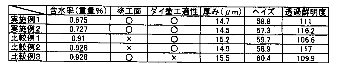
次に、上記紫外線硬化樹脂組成物の固形分100重量部に対して、透光性微粒子として重量平均粒子径が6.75μm、標準偏差が0.57で40℃乾燥で1週間、ポリエチレン製容器に収容し、メッシュで蓋をした環境で保管したポリスチレン系樹脂粒子を25重量部、光重合開始剤である「ルシリンTPO」(BASF社製、化学名:2,4,6−トリメチルベンゾイルジフェニルフォスフィンオキサイド)を5重量部添加し、固形分率が60重量%になるようにプロピレングリコールモノメチルエーテルで希釈して塗布液を調製した。 Next, with respect to 100 parts by weight of the solid content of the ultraviolet curable resin composition, the polyethylene resin container has a weight average particle diameter of 6.75 μm and a standard deviation of 0.57 as a light-transmitting fine particle and is dried at 40 ° C. for one week. 25 parts by weight of polystyrene-based resin particles stored in an environment covered with a mesh and covered with a mesh, “Lucirin TPO” as a photopolymerization initiator (Chemical name: 2,4,6-trimethylbenzoyldiphenylphosphine manufactured by BASF) 5 parts by weight of fin oxide) was added and diluted with propylene glycol monomethyl ether so that the solid content was 60% by weight to prepare a coating solution.
なお、MS−70(エーアンドデイ(株)社製)に透光性微粒子5gをセットし、105℃×3時間で測定された、実施例1で用いた透光性微粒子の含水率は0.675重量%であった。また、JIS K 7209に規定された方法で測定した、実施例1で用いた透光性微粒子を構成する樹脂材料(ポリスチレン系樹脂)の吸水率は0.02%/24hrであった。 In addition, 5 g of translucent fine particles were set in MS-70 (manufactured by A & D Co., Ltd.), and the water content of the translucent fine particles used in Example 1 measured at 105 ° C. for 3 hours was 0.675. % By weight. Further, the water absorption of the resin material (polystyrene resin) constituting the translucent fine particles used in Example 1 measured by the method defined in JIS K 7209 was 0.02% / 24 hr.
この塗布液を、厚さ80μmのトリアセチルセルロース(TAC)フィルム(基材フィルム)上に塗布し、80℃に設定した乾燥機中で1分間乾燥させた。乾燥後の基材フィルムを、上記(1)で作製した鏡面金属製ロールの鏡面に、紫外線硬化性樹脂組成物の層がロール側となるようにゴムロールで押し付けて密着させた。この状態で基材フィルム側より、強度20mW/cm2の高圧水銀灯からの光をh線換算光量で300mJ/cm2となるように照射して、紫外線硬化樹脂組成物の層を硬化させ、平坦な表面を有する光拡散層と基材フィルムとからなる光拡散フィルムを得た。 This coating solution was applied onto a 80 μm thick triacetyl cellulose (TAC) film (base film) and dried for 1 minute in a drier set at 80 ° C. The base film after drying was brought into close contact with the mirror surface of the mirror surface metal roll produced in (1) above with a rubber roll so that the layer of the ultraviolet curable resin composition was on the roll side. In this state, light from a high-pressure mercury lamp having an intensity of 20 mW / cm 2 is irradiated from the base film side so that the amount of light in terms of h-ray is 300 mJ / cm 2, and the layer of the ultraviolet curable resin composition is cured to be flat. A light diffusing film comprising a light diffusing layer having a rough surface and a substrate film was obtained.
<実施例2>
透光性微粒子として、15℃、40%RHで1週間の環境で保管したポリスチレン系樹脂粒子を用いたこと以外は実施例1と同様にして光拡散フィルムを得た。実施例1と同様にしてそれぞれ測定した透光性微粒子の含水率は0.727重量%、透光性微粒子を構成する樹脂材料の吸水率は0.02%/24hrであった。
<Example 2>
A light diffusing film was obtained in the same manner as in Example 1 except that polystyrene resin particles stored in an environment of 1 week at 15 ° C. and 40% RH were used as the light-transmitting fine particles. The water content of the translucent fine particles measured in the same manner as in Example 1 was 0.727% by weight, and the water absorption of the resin material constituting the translucent fine particles was 0.02% / 24 hr.
<比較例1>
透光性微粒子として、40℃、90%RHで1週間の環境で保管したポリスチレン系樹脂粒子を用いたこと以外は実施例1と同様にして光拡散フィルムを得た。実施例1と同様にしてそれぞれ測定した透光性微粒子の含水率は0.91重量%、透光性微粒子を構成する樹脂材料の吸水率は0.02%/24hrであった。
<Comparative Example 1>
A light diffusing film was obtained in the same manner as in Example 1 except that polystyrene resin particles stored in an environment for 1 week at 40 ° C. and 90% RH were used as the translucent fine particles. The water content of the translucent fine particles measured in the same manner as in Example 1 was 0.91% by weight, and the water absorption of the resin material constituting the translucent fine particles was 0.02% / 24 hr.
<比較例2>
透光性微粒子として、−40℃乾燥で1週間の環境で保管したポリスチレン系樹脂粒子を用いたこと以外は実施例1と同様にして光拡散フィルムを得た。実施例1と同様にしてそれぞれ測定した透光性微粒子の含水率は0.928重量%、透光性微粒子を構成する樹脂材料の吸水率は0.02%/24hrであった。
<Comparative example 2>
A light diffusing film was obtained in the same manner as in Example 1 except that polystyrene resin particles stored at -40 ° C. and stored in an environment for 1 week were used as the light-transmitting fine particles. The water content of the translucent fine particles measured in the same manner as in Example 1 was 0.928% by weight, and the water absorption of the resin material constituting the translucent fine particles was 0.02% / 24 hr.
<比較例3>
塗布液にモレキュラーシーブ(モレキュラーシーブ4A、和光純薬工業(株)製)を脱水剤として用いたこと以外は実施例1と同様にして光拡散フィルムを得た。実施例1と同様にしてそれぞれ測定した透光性微粒子の含水率は0.928重量%、透光性微粒子を構成する樹脂材料の吸水率は0.02%/24hrであった。
<Comparative Example 3>
A light diffusion film was obtained in the same manner as in Example 1 except that molecular sieve (Molecular sieve 4A, manufactured by Wako Pure Chemical Industries, Ltd.) was used as a dehydrating agent in the coating solution. The water content of the translucent fine particles measured in the same manner as in Example 1 was 0.928% by weight, and the water absorption of the resin material constituting the translucent fine particles was 0.02% / 24 hr.
実施例1、2および比較例1〜3で得られた光拡散フィルムについて、以下の評価を行った。 The following evaluation was performed about the light-diffusion film obtained in Example 1, 2 and Comparative Examples 1-3.
(a)塗工面
目視にて、以下のように評価した。
(A) Coated surface Visually evaluated as follows.
○:ハジキ、ムラがなく面が綺麗な状態、
×:ハジキ、ムラが発生した状態。
○: Repel, no unevenness, clean surface,
X: State where repellency and unevenness occurred.
(b)ダイ塗工適性
塗布液が、ダイコート方式での塗工に適しているか否かを評価した。
(B) Die coating suitability It was evaluated whether the coating solution was suitable for coating by the die coating method.
○:塗工の際に問題がない状態、
×:液溜めがないために脱水剤を取り除く必要あり。
○: No problem in coating,
X: Since there is no liquid reservoir, it is necessary to remove the dehydrating agent.
(c)光拡散層の厚み
光拡散フィルムの層厚をNIKON社製 DIGIMICRO MH−15(本体)およびZC−101(カウンター)を用いて測定し、基材フィルムの厚み80μmを測定層厚から差し引くことにより光拡散層の厚みを測定した。
(C) Thickness of light diffusing layer The thickness of the light diffusing film is measured using DIGIMICRO MH-15 (main body) and ZC-101 (counter) manufactured by NIKON, and the thickness of the base film is subtracted from the measured layer thickness. Thus, the thickness of the light diffusion layer was measured.
(d)ヘイズ
光学的に透明な粘着剤を用いて、光拡散フィルムを、その基材フィルム側でガラス基板に貼合した測定用サンプルを用いて測定を行なった。上述した測定方法に従う全ヘイズ値および内部ヘイズの測定には、JIS K 7136に準拠したヘイズ透過率計(株式会社村上色彩技術研究所製のヘイズメーター「HM−150」)を用いた。その結果に基づき、上記式(3)より表面ヘイズを算出した。
(D) Haze It measured using the sample for a measurement which bonded the light-diffusion film to the glass substrate on the base film side using the optically transparent adhesive. A haze transmittance meter (haze meter “HM-150” manufactured by Murakami Color Research Laboratory Co., Ltd.) conforming to JIS K 7136 was used to measure all haze values and internal haze according to the measurement method described above. Based on the result, the surface haze was calculated from the above formula (3).
(e)透過鮮明度
光学的に透明な粘着剤を用いて、光拡散フィルムを、その基材フィルム側でガラス基板に貼合した測定用サンプルを用いて測定を行なった。測定には、JIS K 7105に準拠した写像性測定器(スガ試験機株式会社製の「ICM−1DP」)を用いた。ここでいう透過鮮明度は、上述の定義のとおり、JIS K 7105に準拠し、暗部と明部との幅の比が1:1で、その幅が0.125mm、0.5mm、1.0mmおよび2.0mmである4種類の光学くしを用いて測定される透過鮮明度(像鮮明度)の和である。
(E) Transmission clarity Using an optically transparent adhesive, measurement was performed using a measurement sample in which a light diffusion film was bonded to a glass substrate on the base film side. For the measurement, an image clarity measuring device (“ICM-1DP” manufactured by Suga Test Instruments Co., Ltd.) based on JIS K 7105 was used. The transmission definition here is based on JIS K 7105 as defined above, and the ratio of the width between the dark part and the bright part is 1: 1, and the width is 0.125 mm, 0.5 mm, 1.0 mm. And transmission sharpness (image sharpness) measured using four types of optical combs of 2.0 mm.
結果を表1に示す。 The results are shown in Table 1.
Claims (4)
前記塗布液をダイコート方式にて基材フィルム上に塗布する工程と、
紫外線を照射して塗布液を硬化させ、光拡散層を形成する工程と、を有し、
前記透光性微粒子の含水率は、透光性微粒子5gをMS−70(エーアンドデイ(株)社製)にセットし、105℃で3時間の条件で乾燥し、乾燥前の質量を100%として、乾燥前後の質量減少分を計算して求めた値である、光拡散フィルムの製造方法。 A step of preparing a coating liquid by mixing an ultraviolet curable resin, a solvent, and translucent fine particles having a weight average particle diameter of 1 μm or more and a water content of 0.6 to 0.8% by mass;
A step of applying on the substrate film in the coating liquid for die coating method,
Irradiating ultraviolet rays to cure the coating solution, and forming a light diffusion layer ,
The water content of the translucent fine particles was set in MS-70 (manufactured by A & D Co., Ltd.) with 5 g of the translucent fine particles, dried at 105 ° C. for 3 hours, and the mass before drying was 100%. The manufacturing method of the light-diffusion film which is the value calculated | required by calculating the mass loss before and behind drying .
前記光拡散フィルムと偏光フィルムとを貼り合わせる工程と、を有する偏光板の製造方法。 The process of manufacturing a light-diffusion film with the manufacturing method of the light-diffusion film of any one of Claims 1-3 ,
The process of bonding the said light-diffusion film and a polarizing film, The manufacturing method of the polarizing plate which has.
Priority Applications (1)
| Application Number | Priority Date | Filing Date | Title |
|---|---|---|---|
| JP2012071455A JP6058905B2 (en) | 2011-03-31 | 2012-03-27 | Manufacturing method of light diffusion film and manufacturing method of polarizing plate |
Applications Claiming Priority (3)
| Application Number | Priority Date | Filing Date | Title |
|---|---|---|---|
| JP2011079444 | 2011-03-31 | ||
| JP2011079444 | 2011-03-31 | ||
| JP2012071455A JP6058905B2 (en) | 2011-03-31 | 2012-03-27 | Manufacturing method of light diffusion film and manufacturing method of polarizing plate |
Publications (2)
| Publication Number | Publication Date |
|---|---|
| JP2012215867A JP2012215867A (en) | 2012-11-08 |
| JP6058905B2 true JP6058905B2 (en) | 2017-01-11 |
Family
ID=46991961
Family Applications (1)
| Application Number | Title | Priority Date | Filing Date |
|---|---|---|---|
| JP2012071455A Expired - Fee Related JP6058905B2 (en) | 2011-03-31 | 2012-03-27 | Manufacturing method of light diffusion film and manufacturing method of polarizing plate |
Country Status (4)
| Country | Link |
|---|---|
| JP (1) | JP6058905B2 (en) |
| KR (1) | KR20120112097A (en) |
| CN (1) | CN102736143A (en) |
| TW (1) | TWI519827B (en) |
Families Citing this family (6)
| Publication number | Priority date | Publication date | Assignee | Title |
|---|---|---|---|---|
| JP6313974B2 (en) * | 2013-03-29 | 2018-04-18 | 積水化成品工業株式会社 | Crosslinked acrylic resin particles and method for producing the same, resin composition and packaging article |
| US10185063B2 (en) * | 2013-04-30 | 2019-01-22 | Lintec Corporation | Optical-diffusion film for display and reflective display device using same |
| KR101596254B1 (en) | 2014-01-28 | 2016-02-22 | 세키스이가세이힝코교가부시키가이샤 | Cross-linked acrylic particles, method for the production thereof, resin composition and packaging articles |
| CN103969718A (en) * | 2014-05-10 | 2014-08-06 | 宁波东旭成新材料科技有限公司 | Diffusion film preparing method |
| CN109789666B (en) * | 2017-03-30 | 2024-06-04 | 琳得科株式会社 | Composite sheet for forming protective film |
| CN110162199A (en) * | 2018-02-13 | 2019-08-23 | 宸美(厦门)光电有限公司 | Touch panel and preparation method thereof |
Family Cites Families (12)
| Publication number | Priority date | Publication date | Assignee | Title |
|---|---|---|---|---|
| JP3968526B2 (en) * | 2004-03-24 | 2007-08-29 | 第一工業製薬株式会社 | Method for classifying ethylene oxide-butylene oxide copolymer resin pellets |
| JP2007108725A (en) * | 2005-09-15 | 2007-04-26 | Fujifilm Corp | Optical film, antireflection film, polarizing plate and display device using the same |
| US20070058250A1 (en) * | 2005-09-15 | 2007-03-15 | Fuji Photo Film Co., Ltd. | Optical film, antireflection film, polarizing plate using the same and display device |
| KR20080064975A (en) * | 2005-11-15 | 2008-07-10 | 아사히 가세이 케미칼즈 가부시키가이샤 | Optical diffuser plate for liquid crystal display |
| JP2007188070A (en) * | 2005-12-15 | 2007-07-26 | Fujifilm Corp | Optical film, polarizing plate using the same, image display device, and liquid crystal display device |
| KR101382369B1 (en) * | 2006-08-21 | 2014-04-08 | 가부시기가이샤 닛뽕쇼꾸바이 | Microparticle, process for producing microparticle, and, loaded with the microparticle, resin composition and optical film |
| KR101058280B1 (en) * | 2006-12-27 | 2011-08-22 | 가오 가부시키가이샤 | Absence of light diffusion |
| JP2009175335A (en) * | 2008-01-23 | 2009-08-06 | Nippon Shokubai Co Ltd | Antiglare laminate |
| WO2009102027A1 (en) * | 2008-02-15 | 2009-08-20 | Mitsubishi Chemical Corporation | Conjugated polymer, insolubilized polymer, organic electroluminescent device material, composition for organic electroluminescent device, method for producing polymer, organic electroluminescent device, organic el display, and organic el illuminator |
| JP5421141B2 (en) * | 2009-03-24 | 2014-02-19 | 株式会社日本触媒 | Amino resin crosslinked particles and process for producing the same |
| JP5449815B2 (en) * | 2009-03-26 | 2014-03-19 | 住友化学株式会社 | Manufacturing method of polarizing plate |
| JP5419625B2 (en) * | 2009-10-06 | 2014-02-19 | 株式会社日本触媒 | Core-shell particle, light diffusing agent, and light diffusing medium |
-
2012
- 2012-03-27 KR KR1020120030971A patent/KR20120112097A/en not_active Ceased
- 2012-03-27 JP JP2012071455A patent/JP6058905B2/en not_active Expired - Fee Related
- 2012-03-29 TW TW101111153A patent/TWI519827B/en not_active IP Right Cessation
- 2012-03-31 CN CN2012100936900A patent/CN102736143A/en active Pending
Also Published As
| Publication number | Publication date |
|---|---|
| JP2012215867A (en) | 2012-11-08 |
| TW201303380A (en) | 2013-01-16 |
| KR20120112097A (en) | 2012-10-11 |
| CN102736143A (en) | 2012-10-17 |
| TWI519827B (en) | 2016-02-01 |
Similar Documents
| Publication | Publication Date | Title |
|---|---|---|
| CN102483475B (en) | Light-diffusing film, method for producing same, light-diffusing polarizing plate, and liquid crystal display device | |
| CN103026271B (en) | Light-diffusing film, method for producing same, light-diffusing polarizing plate, and liquid crystal display device | |
| JP2011209675A (en) | Light-diffusing film, manufacturing method therefor, light-diffusing polarizing plate, and liquid-crystal display device | |
| JP2011034070A (en) | Light diffusion film and liquid crystal display comprising the same | |
| JP6058905B2 (en) | Manufacturing method of light diffusion film and manufacturing method of polarizing plate | |
| WO2011162133A1 (en) | Light-diffusing polarization plate and liquid-crystal display device | |
| WO2010073985A1 (en) | Optical film and liquid crystal display device comprising same | |
| JP2012078736A (en) | Light diffusion film and manufacturing method for the same, light diffusion polarization plate, and liquid crystal display device | |
| JP2012078420A (en) | Light diffusing polarizer plate, and liquid crystal display device | |
| JP2012008332A (en) | Light-diffusing polarizing plate and liquid crystal display device | |
| TW201042328A (en) | Liquid crystal display device | |
| CN102265194A (en) | Optical film and liquid crystal display device comprising the same | |
| WO2012060457A1 (en) | Light diffusion film, method for manufacturing the light diffusion film, light-diffusing polarization plate, and liquid crystal display device | |
| CN102681037B (en) | Polarizer protective film | |
| WO2010113879A1 (en) | Liquid crystal display device | |
| JP5827811B2 (en) | Liquid crystal display | |
| WO2011162132A1 (en) | Light-diffusing polarization plate and liquid-crystal display device |
Legal Events
| Date | Code | Title | Description |
|---|---|---|---|
| A621 | Written request for application examination |
Free format text: JAPANESE INTERMEDIATE CODE: A621 Effective date: 20150210 |
|
| A977 | Report on retrieval |
Free format text: JAPANESE INTERMEDIATE CODE: A971007 Effective date: 20151130 |
|
| A131 | Notification of reasons for refusal |
Free format text: JAPANESE INTERMEDIATE CODE: A131 Effective date: 20160105 |
|
| A521 | Request for written amendment filed |
Free format text: JAPANESE INTERMEDIATE CODE: A523 Effective date: 20160302 |
|
| A02 | Decision of refusal |
Free format text: JAPANESE INTERMEDIATE CODE: A02 Effective date: 20160809 |
|
| A521 | Request for written amendment filed |
Free format text: JAPANESE INTERMEDIATE CODE: A523 Effective date: 20161017 |
|
| A911 | Transfer to examiner for re-examination before appeal (zenchi) |
Free format text: JAPANESE INTERMEDIATE CODE: A911 Effective date: 20161024 |
|
| TRDD | Decision of grant or rejection written | ||
| A01 | Written decision to grant a patent or to grant a registration (utility model) |
Free format text: JAPANESE INTERMEDIATE CODE: A01 Effective date: 20161206 |
|
| A61 | First payment of annual fees (during grant procedure) |
Free format text: JAPANESE INTERMEDIATE CODE: A61 Effective date: 20161208 |
|
| R150 | Certificate of patent or registration of utility model |
Ref document number: 6058905 Country of ref document: JP Free format text: JAPANESE INTERMEDIATE CODE: R150 |
|
| S531 | Written request for registration of change of domicile |
Free format text: JAPANESE INTERMEDIATE CODE: R313531 |
|
| R350 | Written notification of registration of transfer |
Free format text: JAPANESE INTERMEDIATE CODE: R350 |
|
| LAPS | Cancellation because of no payment of annual fees |