JP6057602B2 - Solid-state imaging device - Google Patents
Solid-state imaging device Download PDFInfo
- Publication number
- JP6057602B2 JP6057602B2 JP2012178366A JP2012178366A JP6057602B2 JP 6057602 B2 JP6057602 B2 JP 6057602B2 JP 2012178366 A JP2012178366 A JP 2012178366A JP 2012178366 A JP2012178366 A JP 2012178366A JP 6057602 B2 JP6057602 B2 JP 6057602B2
- Authority
- JP
- Japan
- Prior art keywords
- operational amplifier
- signal
- transistors
- amplifier
- initialization switch
- Prior art date
- Legal status (The legal status is an assumption and is not a legal conclusion. Google has not performed a legal analysis and makes no representation as to the accuracy of the status listed.)
- Expired - Fee Related
Links
Images


Classifications
-
- H—ELECTRICITY
- H04—ELECTRIC COMMUNICATION TECHNIQUE
- H04N—PICTORIAL COMMUNICATION, e.g. TELEVISION
- H04N25/00—Circuitry of solid-state image sensors [SSIS]; Control thereof
- H04N25/70—SSIS architectures; Circuits associated therewith
- H04N25/76—Addressed sensors, e.g. MOS or CMOS sensors
- H04N25/766—Addressed sensors, e.g. MOS or CMOS sensors comprising control or output lines used for a plurality of functions, e.g. for pixel output, driving, reset or power
-
- H—ELECTRICITY
- H03—ELECTRONIC CIRCUITRY
- H03F—AMPLIFIERS
- H03F3/00—Amplifiers with only discharge tubes or only semiconductor devices as amplifying elements
- H03F3/45—Differential amplifiers
-
- H—ELECTRICITY
- H04—ELECTRIC COMMUNICATION TECHNIQUE
- H04N—PICTORIAL COMMUNICATION, e.g. TELEVISION
- H04N25/00—Circuitry of solid-state image sensors [SSIS]; Control thereof
- H04N25/70—SSIS architectures; Circuits associated therewith
- H04N25/709—Circuitry for control of the power supply
-
- H—ELECTRICITY
- H04—ELECTRIC COMMUNICATION TECHNIQUE
- H04N—PICTORIAL COMMUNICATION, e.g. TELEVISION
- H04N25/00—Circuitry of solid-state image sensors [SSIS]; Control thereof
- H04N25/70—SSIS architectures; Circuits associated therewith
- H04N25/71—Charge-coupled device [CCD] sensors; Charge-transfer registers specially adapted for CCD sensors
- H04N25/75—Circuitry for providing, modifying or processing image signals from the pixel array
Description
本発明は、固体撮像装置に関する。 The present invention relates to a solid-state imaging device.
近年の固体撮像装置は、デジタルカメラ、デジタルビデオカメラ、携帯電話など、様々な機器に使用されており、さらなる高機能化が求められている。特に、多画素化に対する要望が強く、画素サイズ及び画素の信号を読み出すための読み出し回路の縮小が必要不可欠である。列毎に容量帰還型の増幅回路を有する構成の読み出し回路を縮小する場合、容量値の低減が必要となる。この場合、増幅回路を初期化する時に発生するチャージインジェクションによる電荷注入に起因するオフセットが増大する。容量帰還型の増幅回路を初期化する時に生じる、チャージインジェクションやクロックフィードスルーを低減する方法として、以下の方法が知られている。 In recent years, solid-state imaging devices are used in various devices such as digital cameras, digital video cameras, and mobile phones, and further enhancement of functionality is required. In particular, there is a strong demand for increasing the number of pixels, and it is indispensable to reduce a pixel size and a readout circuit for reading out pixel signals. In the case of reducing a readout circuit having a configuration including a capacitive feedback amplifier circuit for each column, it is necessary to reduce the capacitance value. In this case, offset due to charge injection due to charge injection generated when the amplifier circuit is initialized increases. The following methods are known as methods for reducing charge injection and clock feedthrough that occur when initializing a capacitive feedback amplifier circuit.
リセットスイッチと反転増幅回路の負入力端子間に、ソースとドレインを短絡したダミートランジスタを接続する。この時、ダミートランジスタのゲートに印加するパルスは、リセットスイッチを制御するパルスの反転パルスである。これにより、チャージインジェクションやクロックフィードスルーをダミートランジスタのチャネルに吸収する。 A dummy transistor whose source and drain are short-circuited is connected between the reset switch and the negative input terminal of the inverting amplifier circuit. At this time, the pulse applied to the gate of the dummy transistor is an inversion pulse of the pulse for controlling the reset switch. Thereby, charge injection and clock feedthrough are absorbed in the channel of the dummy transistor.
上記の手法の一例として、特許文献1が知られている。
しかしながら、上述のオフセットキャンセル方法は、例えばトランジスタの製造ばらつきにより、設計値の通りにオフセットを低減できないおそれがある。 However, the offset canceling method described above may not be able to reduce the offset as designed, for example, due to transistor manufacturing variations.
本発明の目的は、オフセット量を精度よく調整することができる固体撮像装置を提供することである。 An object of the present invention is to provide a solid-state imaging device capable of accurately adjusting an offset amount.
本発明の固体撮像装置は、光電変換により信号を生成する複数の第1の単位画素と、前記複数の第1の単位画素に接続された第1の出力線と、前記第1の出力線の信号を増幅する第1のアンプとを有し、前記第1のアンプは、第1の演算増幅器と、一端が前記第1の演算増幅器の出力端子に接続される1つの第1の初期化スイッチと、前記1つの第1の初期化スイッチの他端と前記第1の演算増幅器の入力端子との間に接続される第1のトランジスタと、前記1つの第1の初期化スイッチの制御信号のハイレベルの電圧を制御する電源回路とを有し、前記第1のトランジスタは、相互に接続されたソース及びドレインを有し、前記第1のトランジスタの前記ソース及び前記ドレインが前記1つの第1の初期化スイッチに接続されていることを特徴とする。 The solid-state imaging device of the present invention includes a plurality of first unit pixels that generate a signal by photoelectric conversion, a first output line connected to the plurality of first unit pixels, and the first output line. A first amplifier for amplifying a signal, wherein the first amplifier is a first operational amplifier and one first initialization switch having one end connected to the output terminal of the first operational amplifier. When a first transistor that will be connected between the input terminal of the other end and the first operational amplifier of said one of the first initialization switch, said one first control signal of the initialization switch and a power supply circuit for controlling the high level voltage, before Symbol first transistor motor has a source and a drain connected to each other, the source and the drain of the previous SL first transistors comprising said Connected to one first initialization switch. And butterflies.
オフセット量を精度よく調整することができる固体撮像装置を提供することができる。 It is possible to provide a solid-state imaging device capable of accurately adjusting the offset amount.
(第1の実施形態)
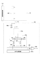
図1は、本発明の第1の実施形態による固体撮像装置の構成例を示すブロック図である。101は単位画素102が行列状に配置された光電変換領域である。114は垂直出力線であり、複数の単位画素102が接続されている。単位画素102は、光電変換により信号を生成する。光電変換領域101の下の読み出し回路ブロック103は、垂直読み出し回路104aと、列アンプ(第1のアンプ)105aと、信号保持部106aと、水平シフトレジスタ107aと、出力アンプ108aを有し、奇数列の第1の単位画素102の信号を読み出す。奇数列の第1の単位画素102は、奇数列の第1の垂直出力線(第1の出力線)114に接続される。光電変換領域101の上の読み出し回路ブロック103は、垂直読み出し回路104bと、列アンプ(第2のアンプ)105bと、信号保持部106bと、水平シフトレジスタ107bと、出力アンプ108bを有し、偶数列の第2の単位画素102の信号を読み出す。偶数列の第2の単位画素102は、偶数列の第2の垂直出力線(第2の出力線)114に接続される。ドライバ109aは垂直読み出し回路104aを制御し、ドライバ109bは垂直読み出し回路104bを制御する。ドライバ110aは列アンプ105aを制御し、ドライバ110bは列アンプ105bを制御する。ドライバ111aは信号保持部106aを制御し、ドライバ111bは信号保持部106bを制御する。垂直走査回路112は、2次元に配列された単位画素102を垂直方向に順次走査する。タイミングジェネレータ(TG)113は、各回路ブロックを制御し、ドライバ109〜111の各々を独立に制御することできる。オフセットキャンセル量自動調整部115aは、列アンプ105aの出力信号116aを入力し、出力信号117aをタイミングジェネレータ113に出力する。同様に、オフセットキャンセル量自動調整部115bは、列アンプ105bの出力信号116bを入力し、出力信号117bをタイミングジェネレータ113に出力する。図1には、ドライバ109、110、111をそれぞれ異なる回路ブロックとして示したが、一つの回路ブロックにしたものであっても良い。また、列アンプ105で増幅された信号をA/D変換するために、各列アンプ105に対応してA/D変換器を設けても良い。
(First embodiment)
FIG. 1 is a block diagram illustrating a configuration example of a solid-state imaging device according to the first embodiment of the present invention.
図2は、図1の単位画素102の構成例を示す回路図である。201は、光を電荷(電子)に変換する光電変換素子である。202は、光電変換素子201で発生した電荷を浮遊部203に転送するための転送MOSトランジスタである。204は、浮遊部203の電位を所定のレベルにリセットするためのリセットMOSトランジスタである。光電変換素子201の電荷をリセットする場合は、トランジスタ204及び202を同時にオンさせればよい。205は増幅MOSトランジスタであり、垂直出力線114に設けられた不図示の電流源とともに、浮遊部203の電位に応じて、ソースの電位が変わるソースフォロアとして動作する。206は増幅MOSトランジスタ205のソースを垂直出力線114に接続するための選択MOSトランジスタである。読み出したい行の選択MOSトランジスタ206をオンさせることで、読み出したい光電変換素子201の信号を垂直出力線114に読み出すことができる。
FIG. 2 is a circuit diagram illustrating a configuration example of the
図3は、図1の読み出し回路ブロック103の1列分の構成例を示す回路図である。垂直線読み出し回路104aは、増幅MOSトランジスタ205の負荷としての電流源である。この電流源104aの電流値と、増幅MOSトランジスタ205のゲート電圧によって、垂直出力線114の電位が決まる。列アンプ105aは、垂直出力線114のノードXの電圧を増幅し、信号保持部106aのノードYに出力する。信号保持部106aは、スイッチ301,302と、N信号保持容量303と、S信号保持容量304と、スイッチ305,306とを有する。N信号保持容量303は、単位画素102の浮遊部203をリセットした時の、列アンプ105aで増幅された垂直出力線114の電位(ノイズ信号)を保持する。S信号保持容量304は、列アンプ105aで増幅された、単位画素102の光電変換素子201で発生した電荷が、浮遊部203に転送された後の垂直出力線114の電位(画素信号)を保持する。水平走査回路107aは、N信号保持容量303及びS信号保持容量304が信号を保持した後の水平転送期間に、スイッチ305及び306をオンさせて、N信号保持容量303及びS信号保持容量304の信号を、それぞれ水平転送線307及び308に転送する。出力アンプ108aは、水平転送線307のノイズ信号と水平転送線308の画素信号とを差動増幅して出力する。
FIG. 3 is a circuit diagram showing a configuration example of one column of the
図4は、列アンプ105aの構成例を示す回路図である。列アンプ105bも、列アンプ105aと同様の構成を有する。入力容量402は、ノードXと演算増幅器(差動増幅器)401の反転入力端子との間に接続され、垂直出力線114の電位をクランプする。フィードバック容量403は、演算増幅器401の反転入力端子と出力端子との間に接続される。列アンプ105aのゲインは、フィードバック容量403と入力容量402との容量値の比で決まる。初期化MOSトランジスタ404は、入力容量402を初期化するための初期化スイッチであり、制御信号o_pcにより制御される。初期化MOSトランジスタ404は、その一端が演算増幅器401の出力端子に接続される。オフセット調整部405は、初期化MOSトランジスタ404の他端と演算増幅器401の反転入力端子間に接続される。オフセット調整部405及び初期化MOSトランジスタ404の直列接続回路は、演算増幅器401の反転入力端子と出力端子との間に接続される。演算増幅器401の非反転入力端子は、基準電位Vrefに接続される。演算増幅器401の出力端子は、ノードYに接続される。
FIG. 4 is a circuit diagram showing a configuration example of the
図5は、本実施形態による固体撮像装置の駆動方法を示すタイミングチャートである。信号presは、図2のリセットMOSトランジスタ204を制御するパルスである。信号o_pcは、図4の初期化MOSトランジスタ404を制御するパルスである。信号o_pcbは、図4のオフセット調整部405を制御するパルスである。信号ptxは、図2の転送MOSトランジスタ202を制御するパルスである。信号ptnは、図3のスイッチ301を制御するパルスである。信号ptsは、図3のスイッチ302を制御するパルスである。信号pselは、図2の選択MOSトランジスタ206を制御するパルスである。
FIG. 5 is a timing chart showing the driving method of the solid-state imaging device according to the present embodiment. The signal pres is a pulse for controlling the reset MOS transistor 204 in FIG. The signal o_pc is a pulse for controlling the
時刻t1の前では、信号presがハイレベルになり、リセットMOSトランジスタ204がオンし、浮遊部203が電源電圧にリセットされた状態にある。 Prior to time t1, the signal pres is at a high level, the reset MOS transistor 204 is turned on, and the floating portion 203 is reset to the power supply voltage.
時刻t1では、読み出す行の信号presがローレベルになり、リセットMOSトランジスタ204がオフする。これにより、浮遊部203は、フローティングノードとなる。この時、読み出す行の信号pselがハイレベルとなり、選択MOSトランジスタ206がオンする。これにより、増幅MOSトランジスタ205のソースが、選択MOSトランジスタ206を介して、垂直出力線114に接続される。垂直出力線114に接続された電流源104aの電流を増幅MOSトランジスタ205が流すようになる。この時の垂直出力線114の電位は、増幅MOSトランジスタ205のゲート電位で決まる。つまり、垂直出力線114の電位は、浮遊部204の電位から増幅MOSトランジスタ205の閾値電圧Vthとオーバードライブ電圧ΔVovだけ下がった電位に固定される。
At time t1, the signal pres for the row to be read becomes a low level, and the reset MOS transistor 204 is turned off. Thereby, the floating portion 203 becomes a floating node. At this time, the signal psel of the row to be read becomes high level, and the selection MOS transistor 206 is turned on. As a result, the source of the amplification MOS transistor 205 is connected to the
時刻t2では、信号o_pcがハイレベルになる。これにより、列アンプ105aの初期化MOSトランジスタ404がオンし、リセットされた浮遊部203の電位で決まった垂直出力線114の電位を、入力容量402にクランプする。時刻t2では、信号o_pcbも遷移しているが、信号o_pcbに関してはオフセット調整部405の説明を行う時に詳しく述べるので、今は説明を省略する。
At time t2, the signal o_pc becomes high level. As a result, the
時刻t3では、信号o_pcがローレベルになり、列アンプ105aの初期化MOSトランジスタ404がオフする。この時、発生するチャージインジェクションやクロックフィードスルーが、列アンプ105aのオフセットを増長する。
At time t3, the signal o_pc becomes low level, and the
時刻t4では、信号ptnがハイレベルになり、スイッチ301がオンし、N信号保持容量303に、アンプ初期化時の列アンプ105aの出力信号(N信号)を書き込む。
At time t4, the signal ptn becomes high level, the
時刻t5では、信号ptnがローレベルになり、N信号保持容量303へのN信号の書き込みが終了する。
At time t5, the signal ptn becomes low level, and the writing of the N signal to the N
時刻t6では、信号ptxがハイレベルになり、転送MOSトランジスタ202がオンし、光電変換素子201で光電変換された電子が浮遊部203に転送される。この転送された電子によって、浮遊部203の電圧がリセット時から低下する。これに従って、垂直出力線114の電位が低下する。低下した垂直出力線114の電位は、列アンプ105aで反転増幅される。この時の反転増幅のゲインは、入力容量402とフィードバック容量403の比で決まる。増幅された光電変換素子201の信号をS信号と呼ぶことにする。
At time t6, the signal ptx becomes high level, the transfer MOS transistor 202 is turned on, and the electrons photoelectrically converted by the photoelectric conversion element 201 are transferred to the floating portion 203. Due to the transferred electrons, the voltage of the floating portion 203 decreases from the time of reset. Accordingly, the potential of the
時刻t7では、信号ptxがローレベルになり、転送MOSトランジスタ202がオフし、光電変換素子201から浮遊部203への電子の転送が終了する。 At time t7, the signal ptx becomes low level, the transfer MOS transistor 202 is turned off, and the transfer of electrons from the photoelectric conversion element 201 to the floating portion 203 is completed.
時刻t8では、信号ptsがハイレベルになり、スイッチ302がオンし、列アンプ105aで増幅されたS信号がS信号保持容量304に書き込まれる。
At time t8, the signal pts goes high, the
時刻t9では、信号ptsがローレベルになり、スイッチ302がオフし、S信号保持容量304へのS信号の書き込みが終了する。
At time t9, the signal pts goes low, the
時刻t10では、信号pselがローレベルになり、選択MOSトランジスタ206がオフし、単位画素102が垂直出力線114から切り離される。
At time t10, the signal psel becomes low level, the selection MOS transistor 206 is turned off, and the
その後、水平走査が開始され、水平走査回路107aは、順次、スイッチ305及び306をオンする信号を出力する。水平走査回路107aからハイレベルの信号がスイッチ305及び306に供給されると、N信号保持容量303に保持されていた信号は、水平転送線307へ転送され、S信号保持容量304に保持されていた信号は、水平転送線308に転送される。水平転送線308は、出力アンプ108aの正転入力端子に接続され、水平転送線307は、出力アンプ108aの反転入力に接続される。そして、出力アンプ108aは、S信号からN信号を引いた電圧を出力する。
Thereafter, horizontal scanning is started, and the
水平転送期間が終了すると、次の行の読み出しシーケンスに移行する。次の行の読み出しシーケンスは、先に述べた動作の繰り返しである。 When the horizontal transfer period ends, the process proceeds to the read sequence for the next row. The read sequence for the next row is a repetition of the operations described above.
図6は、オフセット調整部405の構成例を示す回路図である。600、601、・・・、60nは、それぞれチャージインジェクション時に再分布した電荷をチャネルに吸収するためのダミーMOSトランジスタである。各トランジスタ600〜60nのソース及びドレインは、相互に接続しており、図4の演算増幅器401の反転入力端子に接続されている。オフセット調整部405は、任意のn個のダミーMOSトランジスタ600〜60nを有している。ダミーMOSトランジスタ600〜60nのゲートには、それぞれ信号pcb0〜pcbnが入力される。信号pcb0〜pcbnにより、駆動するダミーMOSトランジスタ600〜60nの個数を変え、ダミーMOSトランジスタ600〜60nのゲートサイズを制御することにより、チャージインジェクションにより再分布した電荷の吸収量を変える。
FIG. 6 is a circuit diagram illustrating a configuration example of the offset
図7は、図6のオフセット調整部405を制御するためのドライバ110aの一部の構成例を示す回路図である。700、701、・・・、70nは、それぞれ図6のダミーMOSトランジスタ600、601、・・・、60nを駆動するためのバッファ回路である。710、711、・・・、71nは、それぞれ、バッファ回路700、701、・・・、70nを動作させるか、させないかを決める論理積(AND)回路である。論理積回路710、711、・・・、71nは、信号pcbと、信号sel0、sel1、・・・、selnとの論理積をとる。信号sel0、sel1、・・・、selnは、どのダミーMOSトランジスタ600、601、・・・、60nに制御信号pcbを印加するかを決める信号である。信号sel0〜selnがそれぞれハイレベルの時に、信号pcbはバッファ回路700〜70nに伝達され、制御信号pcb0〜pcbnとして、ダミーMOSトランジスタ600〜60nのゲートに印加される。信号sel0〜selnがそれぞれローレベルの時に、信号pcbはバッファ回路700〜70nに伝達されず、制御信号pcb0〜pcbnは、ダミーMOSトランジスタ600〜60nのゲートに印加されない。
FIG. 7 is a circuit diagram showing a configuration example of a part of the
オフセット調整部405で吸収する電荷量は、次式(1)で決まる。
Q[C]=Cox・W・L・Vgs ・・・(1)
The amount of charge absorbed by the offset
Q [C] = Cox · W · L · Vgs (1)
ここで、Coxは単位面積当たりのゲート容量、WはダミーMOSトランジスタのゲート幅、LはダミーMOSトランジスタのゲート長、VgsはダミーMOSトランジスタのゲート及びソース間の電圧である。 Here, Cox is the gate capacitance per unit area, W is the gate width of the dummy MOS transistor, L is the gate length of the dummy MOS transistor, and Vgs is the voltage between the gate and source of the dummy MOS transistor.
例えば、ダミーMOSトランジスタ600、601、・・・、60nのサイズは、列アンプ105aの初期化MOSトランジスタ404の1/10程度のサイズである。この時、n=9とし、ダミーMOSトランジスタは全部で10個あるとする。この場合、吸収できる電荷量は、0 〜 Cox・W・L・Vgs [C]の間であり、最少調整幅は、次式(2)になる。
1/10・Cox・W・L・Vgs[C] ・・・(2)
For example, the size of the
1/10 · Cox · W · L · Vgs [C] (2)
一般的に言われるチャージインジェクションの再分布量は、列アンプ105aの初期化MOSトランジスタ404のソース及びドレインに対して、それぞれ、次式(3)になると言われている。
Q1[C]=1/2・Cox・W1・L1・Vgs1 ・・・(3)
It is said that the charge injection redistribution amount generally referred to is expressed by the following equation (3) with respect to the source and drain of the
Q1 [C] = 1/2 · Cox · W1 · L1 · Vgs1 (3)
ここで、W1は初期化MOSトランジスタ404のゲート幅、L1は初期化MOSトランジスタ404のゲート長、Vgs1は初期化MOSトランジスタ404のゲート及びソース間の電圧である。
Here, W1 is the gate width of the
また、次式(4)が成り立つので、本実施形態ではオフセットが正に出ても負に出ても、それをキャンセルするように調整可能である。
1/2・Cox・W1・L1・Vgs1
=1/10・5・Cox・W・L・Vgs (Vgs1=Vgs) ・・・(4)
Further, since the following expression (4) holds, in this embodiment, adjustment can be made so as to cancel the offset regardless of whether it is positive or negative.
1/2 ・ Cox ・ W1 ・ L1 ・ Vgs1
= 1/10 · 5 · Cox · W · L · Vgs (Vgs1 = Vgs) (4)
図8(A)は、図7のバッファ回路700、701、・・・、70nの構成例を示す回路図である。バッファ回路700、701、・・・、70nは、信号pcbを入力し、信号o_pcbを出力する。電流源802は、インバータのPMOSトランジスタのソースと電源電圧Vpcbhのノードとの間に接続されている。この電流源802の電流値を変えることにより、図10に示すように、信号o_pcbの立ち上がりの傾きを制御することができる。電流源802は、有効/無効設定が可能で、無効時は電流源802が無いものとして動作する。
FIG. 8A is a circuit diagram showing a configuration example of the
図8(B)は、ドライバ110a内のバッファ回路の構成例を示す回路図であり、このバッファ回路は、図4の初期化MOSトランジスタ404のゲートに信号o_pcを出力する。このバッファ回路は、信号pcを入力し、信号o_pcを出力する。信号pcは、信号pcbの反転信号である。電流源801は、インバータのNMOSトランジスタのソースとグランド電位ノードとの間に接続されている。電流源801の電流値を変えることにより、図10に示すように、信号o_pcの立ち下がりの傾きを制御することができる。電流源801は、有効/無効設定が可能で、無効時は電流源801が無いものとして動作する。
FIG. 8B is a circuit diagram illustrating a configuration example of the buffer circuit in the
固体撮像装置は、図1に示すように、列アンプ105a及び105bの片側に、ドライバ110a及び110bを配置する。従って、ドライバ110a及び110bの近くと遠くで、信号o_pc及びo_pcbの遅延時間が異なる。これにより、オフセットの左右差が発生する。信号o_pc及びo_pcbのパルスの立ち下がり及び立ち上がりを制御することにより、遅延時間を低減することができ、オフセットの左右差を低減することができる。
As shown in FIG. 1, in the solid-state imaging device,
図10のように、信号o_pcは、時刻t2でローレベルから電源電圧(ハイレベル)Vpchに立ち上がり、時刻t3で電源電圧(ハイレベル)Vpchからローレベルに向けて立ち下がりを開始する。時刻t3−2で、初期化MOSトランジスタ404の電圧Vgsが閾値電圧Vth以下となり、初期化MOSトランジスタ404のチャネルが消失する。時刻t3−3で、信号o_pcはローレベルになる。
As shown in FIG. 10, the signal o_pc rises from the low level to the power supply voltage (high level) Vpch at time t2, and starts to fall from the power supply voltage (high level) Vpch to the low level at time t3. At time t3-2, voltage Vgs of
これに対して、信号o_pcbは、時刻t2で電源電圧(ハイレベル)Vpcbhからローレベルに立ち下がり、時刻t3でローレベルから電源電圧(ハイレベル)Vpcbhに向けて立ち上がりを開始する。時刻t3−2では、ダミーMOSトランジスタ600、601、・・・、60nの電圧Vgsは閾値電圧Vthになる。初期化MOSトランジスタ404のチャネルが消失した後の、時刻t3−2以降にチャネルが発生する。時刻t3−4では、信号o_pcbは電源電圧(ハイレベル)Vpcbhになる。
In contrast, the signal o_pcb falls from the power supply voltage (high level) Vpcbh to the low level at time t2, and starts rising from the low level to the power supply voltage (high level) Vpcbh at time t3. At time t3-2, the voltage Vgs of the
以上のように、初期化MOSトランジスタ404のチャネルが消失してから、ダミーMOSトランジスタ600、601、・・・、60nのチャネルを発生させた方が、水平方向のオフセットキャンセル量のばらつきを抑制できる。したがって、そうなるように、信号o_pc及びo_pcbを制御することが好ましい。
As described above, when the channel of the
図9は、図8(A)の電源電圧Vpcbh又は図8(B)の電源電圧Vpchを生成する電源回路の構成例を示す図である。制御信号o_pc及びo_pcbのハイレベルの電圧Vpch及びVpcbhは、図9の電源回路を使用することで変更制御することができる。図9の電源回路は、図8(A)の電源電圧Vpcbhのための電源回路及び図8(B)の電源電圧Vpchのための電源回路の2つ有する。なお、読み出し回路ブロック103の個数分だけ、別々に用意しても良い。 FIG. 9 is a diagram illustrating a configuration example of a power supply circuit that generates the power supply voltage Vpcbh in FIG. 8A or the power supply voltage Vpch in FIG. The high-level voltages Vpch and Vpcbh of the control signals o_pc and o_pcb can be changed and controlled by using the power supply circuit of FIG. The power supply circuit in FIG. 9 includes two power supply circuits for the power supply voltage Vpcbh in FIG. 8A and the power supply circuit for the power supply voltage Vpch in FIG. Note that the same number of read circuit blocks 103 may be prepared separately.
900はユニティーゲインバッファであり、反転入力端子が出力端子に接続される。スイッチ901、902、・・・、90(n−2)、90(n−1)、90nのどれかをオンにする。これにより、電源電圧ノード及びグランド電位ノード間に接続された抵抗によって抵抗分割された電圧が、ユニティーゲインバッファ900の正転入力端子に供給される。ユニティーゲインバッファ900の出力端子は、図8(A)の電源電圧Vpcbh又は図8(B)の電源電圧Vpchのノードに接続される。これにより、図10の信号o_pc及びo_pcbのハイレベルVpch及びVpcbhを変えることができる。
A
信号o_pc及びo_pcbのハイレベルVpch及びVpcbhを変えることは、初期化MOSトランジスタ404又はダミーMOSトランジスタ600、601、・・・、60nの電圧Vgsを変えることである。つまり、再分布するチャネルの電荷量の制御、又はダミーMOSトランジスタ600、601、・・・、60nのチャネルに吸収する電荷量を制御することができる。
Changing the high levels Vpch and Vpcbh of the signals o_pc and o_pcb is changing the voltage Vgs of the
本実施形態では、(1)ダミーMOSトランジスタ600、601、・・・、60nの個数の制御、(2)信号o_pcのハイレベルの制御、(3)信号o_pcbのハイレベルの制御を行う。これにより、チャージインジェクションのキャンセル量、つまり列アンプ105a及び105bの出力オフセット量を調整することができる。上記の(1)〜(3)を同時に行っても良いし、どれか1つ、あるは2つ用いてオフセットを調整してもよい。
In this embodiment, (1) control of the number of
図11は、オフセットキャンセル量自動調整部115a及び115bの構成例を示す図である。コンパレータ1101は、正転入力端子に任意の基準電圧Vcompが入力され、反転入力端子に列アンプ105a又は105bの出力信号116a又は116bが入力される。この時の出力信号116a又は116bは、単位画素102が遮光されたオプティカルブラック画素のレベルを出力する列の列アンプ105a又は105bを用いる。キャリブレーションの初期状態は、オフセットキャンセル量の調整無しの状態で始める。本実施形態では、初期化MOSトランジスタ404はNMOSトランジスタであるため、オフセットキャンセル無しの状態では、列アンプ105a又は105bの出力オフセットはプラスになる。以下に、詳しい調整方法を示す。
FIG. 11 is a diagram illustrating a configuration example of the offset cancellation amount
論理回路1102は、コンパレータ1101の出力が反転するまで、1垂直走査期間(1V)に1回入るパルスVDを、カウンタ1103のクロック端子に供給する。カウンタ1103のカウント値は、出力信号117a又は117bとしてタイミングジェネレータ113に入力される。タイミングジェネレータ113は、このカウンタ値に対応したオフセットキャンセル調整量を、図7の制御信号sel1〜selnとしてドライバ110a及び110bに出力する。
The
以上のように、列アンプ105a又は105bの出力信号116a又は116bが基準電圧Vcompより低くなり、コンパレータ1101の出力信号が反転するまで、カウンタ1103はカウントアップし、オフセットキャンセル調整量を増やしていく。この動作により、プラスのオフセットを減らしていく。コンパレータ1101の基準電圧Vcompを列アンプ105a及び105bの基準電位Vrefと同じ電圧にしておけば、列アンプ105a及び105bの出力信号116a及び116bが基準電位Vref近辺に来るようにオフセットを調整することができる。
As described above, the
本実施形態では、ドライバ110aとドライバ110bとは、それぞれ異なる制御をしてもよいし、同じ制御をしてもよい。すなわち、列アンプ105bのオフセット調整部405は、列アンプ105aのオフセット調整部405に対してオフセットキャンセル量が異なるようにすることができる。また、他の調整方法として、半導体チップ出荷時にオフセット量を測定し、それをキャンセルする設定値を半導体チップ毎に設定することもできる。
In the present embodiment, the
(第2の実施形態)
図12は、本発明の第2の実施形態による列アンプ105aの構成例を示す回路図である。列アンプ105bも、列アンプ105aと同様の構成を有する。以下、本実施形態が第1の実施形態と異なる点を説明する。図12の列アンプ105aは、図4の列アンプ105aに対して、スイッチ1201が追加されている。スイッチ1201は、フィードバック容量403及びノードY間に接続され、加算モードにおいて、フィードバック容量403を用いて信号の加算を行うためのスイッチである。スイッチ1201は、制御信号paddとその反転信号paddbによって制御される。非加算モードでは、スイッチ1201を常にオン状態にしていれば、第1の実施形態で説明した動作ができる。
(Second Embodiment)
FIG. 12 is a circuit diagram showing a configuration example of the
図13は、本実施形態による固体撮像装置の駆動方法を示すタイミングチャートである。以下、図13のタイミングチャートが図5のタイミングチャートと異なる点を説明する。先に述べたように、信号paddは、図12のスイッチ1201を制御するパルスである。スイッチ1201を制御するためのもう一つのパルスである信号paddbは、信号paddの反転信号なので、図13には記載しない。
FIG. 13 is a timing chart showing the driving method of the solid-state imaging device according to the present embodiment. Hereinafter, differences between the timing chart of FIG. 13 and the timing chart of FIG. 5 will be described. As described above, the signal padd is a pulse for controlling the
時刻t8a〜t9aでは、信号ptsはローレベルのままであり、スイッチ302はオフしたままである。よって、N行目のS信号をS信号保持容量304に書き込まない。
From time t8a to t9a, the signal pts remains at the low level, and the
時刻t11〜t12の間、信号paddがローレベルになり、スイッチ1201がオフする。これにより、時刻t6〜t7の間に増幅されたS信号をフィードバック容量403に保持する。スイッチ1201がオフしている間の、時刻t2b〜t3bで、信号o_pcがハイレベルになり、列アンプ105a及び105bが初期化される。この時、スイッチ1201がオフしているので、フィードバック容量403に保持しているN行目のS信号はリセットされない。N行目のS信号は、N行目読み出し時の列アンプオフセットを含んだ次式(5)の電圧Vout1sになる。
Vout1s=Vs1+Vofs ・・・(5)
During time t11 to t12, the signal padd becomes low level, and the
Vout1s = Vs1 + Vofs (5)
ここで、Vs1はN行目のS信号を列アンプ105a又は105bで増幅した信号、Vofs列アンプ105a又は105bの出力オフセットである。
Here, Vs1 is a signal obtained by amplifying the S signal in the Nth row by the
時刻t3bでは、信号o_pcがローレベルになり、N+1行目読み出しのための列アンプ105a及び105bのリセットが終了する。この時、列アンプ105a及び105bの出力には、列アンプ105a及び105bのリセット時のチャージインジェクションによるオフセットが現れる。
At time t3b, the signal o_pc becomes low level, and the resetting of the
時刻t12では、信号paddがハイレベルになり、スイッチ1201がオンする。これにより、列アンプ105a及び105bの出力電圧Vout2nは、次式(6)のように、N行目のS信号Vsと、N+1行目の列アンプのオフセットVofsが重畳した電圧になる。
Vout2n=Vs+Vofs
=(Vs1+Vofs)+Vofs
=Vs1+2Vofs ・・・(6)
At time t12, the signal padd goes high and the
Vout2n = Vs + Vofs
= (Vs1 + Vofs) + Vofs
= Vs1 + 2Vofs (6)
時刻t4b〜t5bにおいて、この時刻の列アンプ105a及び105bの出力はN行目のS信号を含んだレベルであるため、信号ptnをローレベルのままにしてN信号保持容量303への信号の書き込みを行わない。この時、N信号保持容量303に保持されている信号Vout1nは、次式(7)である。
Vout1n=Vofs ・・・(7)
At times t4b to t5b, the outputs of the
Vout1n = Vofs (7)
N+1行目読み出し期間内の時刻t6〜t7では、N+1行目のS信号が読み出され、列アンプ105a又は105bで増幅される。この時の列アンプ105a又は105bの出力電圧Vout2は、次式(8)となる。
Vout2s=Vs1+Vs2+2Vofs ・・・(8)
At times t6 to t7 within the read-out period of the (N + 1) th row, the S signal of the (N + 1) th row is read and amplified by the
Vout2s = Vs1 + Vs2 + 2Vofs (8)
ここで、Vs2は、N+1行目のS信号を列アンプ105a又は105bで増幅した信号である。
Here, Vs2 is a signal obtained by amplifying the S signal of the (N + 1) th row by the
時刻t8b〜t9bでは、信号ptsがハイレベルになり、スイッチ302がオンし、S信号保持容量304に電圧Vout2sが書き込まれる。
From time t8b to t9b, the signal pts is at a high level, the
その後、水平転送期間にスイッチ305及び306がオンして、N信号保持容量303及びS信号保持容量304に保持していた信号がそれぞれ水平転送線307及び308に読み出され、出力アンプ108a又は108bで差動増幅されて出力される。
Thereafter, the
この時の出力電圧は、次式(9)となる。
G・(Vout2s−Vout1n)
=G・(Vs1+Vs2+Vofs) ・・・(9)
The output voltage at this time is expressed by the following equation (9).
G · (Vout2s-Vout1n)
= G · (Vs1 + Vs2 + Vofs) (9)
ここで、Gは、次式(10)で表される。
G=Gamp・C1/(C1+C2) ・・・(10)
Here, G is represented by the following equation (10).
G = Gamp · C1 / (C1 + C2) (10)
ここで、Gampは出力アンプ108a又は108bのゲイン、C1は保持容量303又は304の容量、C2は水平転送線307又は308の寄生容量である。Gampが1であって、水平転送線307及び308にN信号及びS信号を転送した時には、水平転送線307及び308の寄生容量により、Gは1倍以下になる。
Here, Gamp is the gain of the
式(8)から分かるように、本実施形態の動作方法では、列アンプ105a及び105bの出力電圧に、2回分の列アンプオフセットVofsが乗る。第1の実施形態のような、列アンプ105a及び105bのフィードバック容量403で加算を行わない場合は、オフセットキャンセル無しの時に、オフセットVofsだけ列アンプ105a及び105bにオフセットが発生する。つまり、駆動の違い(動作モードの違い)により、オフセットキャンセル量の調整量を変える必要がある。例えば、本実施形態の加算モードの駆動では、第1の実施形態の非加算モードの駆動に対して、2倍のオフセットが発生するので、キャンセル量の調整量を、第1の実施形態の2倍に大きく設定するとよい。
As can be seen from Equation (8), in the operation method of this embodiment, the column amplifier offset Vofs for two times is multiplied by the output voltages of the
このように、オフセット調整部405は、動作モードに応じて、オフセットキャンセル量を変えると、どの動作モードにおいても同じダイナミックレンジを確保することができる。また、フィードバック容量403を可変にして、列アンプ105a及び105bのゲインを可変にした場合においても、出力に現れるオフセット量が変わる。従って、ゲイン設定毎(モード毎)に、オフセットキャンセル量の調整値を変えた方がよい。
In this way, the offset
なお、上記実施形態は、何れも本発明を実施するにあたっての具体化の例を示したものに過ぎず、これらによって本発明の技術的範囲が限定的に解釈されてはならないものである。すなわち、本発明はその技術思想、又はその主要な特徴から逸脱することなく、様々な形で実施することができる。 The above-described embodiments are merely examples of implementation in carrying out the present invention, and the technical scope of the present invention should not be construed in a limited manner. That is, the present invention can be implemented in various forms without departing from the technical idea or the main features thereof.
102 単位画素、105a,105b 列アンプ、114 垂直出力線、401 演算増幅器、404 初期化MOSトランジスタ、405 オフセット調整部 102 unit pixel, 105a, 105b column amplifier, 114 vertical output line, 401 operational amplifier, 404 initialization MOS transistor, 405 offset adjustment unit
Claims (13)
前記複数の第1の単位画素に接続された第1の出力線と、
前記第1の出力線の信号を増幅する第1のアンプとを有し、
前記第1のアンプは、
第1の演算増幅器と、
一端が前記第1の演算増幅器の出力端子に接続される1つの第1の初期化スイッチと、
前記1つの第1の初期化スイッチの他端と前記第1の演算増幅器の入力端子との間に接続される第1のトランジスタと、
前記1つの第1の初期化スイッチの制御信号のハイレベルの電圧を制御する電源回路とを有し、
前記第1のトランジスタは、相互に接続されたソース及びドレインを有し、
前記第1のトランジスタの前記ソース及び前記ドレインが前記1つの第1の初期化スイッチに接続されていることを特徴とする固体撮像装置。 A plurality of first unit pixels that generate signals by photoelectric conversion;
A first output line connected to the plurality of first unit pixels;
A first amplifier for amplifying the signal of the first output line;
The first amplifier is
A first operational amplifier;
A first initialization switch having one end connected to the output terminal of the first operational amplifier;
A first transistor which Ru is connected between the input terminal of the other end and the first operational amplifier of said one of the first initialization switch,
A power supply circuit for controlling a high level voltage of the control signal of the one first initialization switch ,
Before SL first transistor motor has a source and a drain connected to each other,
The solid-state imaging device, characterized in that the source and the drain of the previous SL first transistor motor is connected to said one first initialization switch.
前記複数の第1の単位画素に接続された第1の出力線と、
前記第1の出力線の信号を増幅する第1のアンプとを有し、
前記第1のアンプは、
第1の演算増幅器と、
一端が前記第1の演算増幅器の出力端子に接続される1つの第1の初期化スイッチと、
前記1つの第1の初期化スイッチの他端と前記第1の演算増幅器の入力端子との間に接続される第1のトランジスタと、
前記第1のトランジスタのゲートに供給する制御信号のハイレベルの電圧を制御する電源回路とを有し、
前記第1のトランジスタは、相互に接続されたソース及びドレインを有し、
前記第1のトランジスタの前記ソース及び前記ドレインが前記1つの第1の初期化スイッチに接続されていることを特徴とする固体撮像装置。 A plurality of first unit pixels that generate signals by photoelectric conversion;
A first output line connected to the plurality of first unit pixels;
A first amplifier for amplifying the signal of the first output line;
The first amplifier is
A first operational amplifier;
A first initialization switch having one end connected to the output terminal of the first operational amplifier;
A first transistor which Ru is connected between the input terminal of the other end and the first operational amplifier of said one of the first initialization switch,
A power supply circuit for controlling a high level voltage of a control signal supplied to the gate of the first transistor ,
Before SL first transistor motor has a source and a drain connected to each other,
The solid-state imaging device, characterized in that the source and the drain of the previous SL first transistor motor is connected to said one first initialization switch.
前記複数の第1のトランジスタのそれぞれは、相互に接続されたソース及びドレインを有し、Each of the plurality of first transistors has a source and a drain connected to each other,
前記複数の第1のトランジスタのそれぞれの前記ソース及び前記ドレインが前記1つの第1の初期化スイッチに接続されていることを特徴とする請求項1又は2記載の固体撮像装置。The solid-state imaging device according to claim 1, wherein the source and the drain of each of the plurality of first transistors are connected to the one first initialization switch.
前記複数の第2の単位画素に接続された第2の出力線と、
前記第2の出力線の信号を増幅する第2のアンプとを有し、
前記第2のアンプは、
第2の演算増幅器と、
一端が前記第2の演算増幅器の出力端子に接続される1つの第2の初期化スイッチと、
前記1つの第2の初期化スイッチの他端と前記第2の演算増幅器の入力端子との間に接続される複数の第2のトランジスタとを有し、
前記複数の第2のトランジスタのそれぞれは、相互に接続されたソース及びドレインを有し、
前記複数の第2のトランジスタのそれぞれの前記ソース及び前記ドレインが前記1つの第2の初期化スイッチに接続されていることを特徴とする請求項3又は4記載の固体撮像装置。 A plurality of second unit pixels that generate signals by photoelectric conversion;
A second output line connected to the plurality of second unit pixels;
A second amplifier for amplifying the signal of the second output line;
The second amplifier is
A second operational amplifier;
One second initialization switch having one end connected to the output terminal of the second operational amplifier;
A plurality of second transistors connected between the other end of the one second initialization switch and an input terminal of the second operational amplifier;
Each of the plurality of second transistors has a source and a drain connected to each other,
5. The solid-state imaging device according to claim 3 , wherein the source and the drain of each of the plurality of second transistors are connected to the one second initialization switch.
前記複数の第2のトランジスタは第2のオフセット調整部を構成し、
前記第2のオフセット調整部は、前記第1のオフセット調整部に対してオフセットキャンセル量が異なることを特徴とする請求項5記載の固体撮像装置。 The plurality of first transistors constitute a first offset adjustment unit,
The plurality of second transistors constitute a second offset adjustment unit,
The solid-state imaging device according to claim 5, wherein the second offset adjustment unit has an offset cancellation amount different from that of the first offset adjustment unit.
前記第1のオフセット調整部は、動作モードに応じて、オフセットキャンセル量を変えることを特徴とする請求項3〜6のいずれか1項に記載の固体撮像装置。 The plurality of first transistors constitute a first offset adjustment unit,
The solid-state imaging apparatus according to claim 3, wherein the first offset adjustment unit changes an offset cancellation amount according to an operation mode.
前記複数の第1のトランジスタは第1のオフセット調整部を構成し、
前記第1のオフセット調整部は、前記加算モードにおける調整量の方が前記非加算モードにおける調整量よりも大きいことを特徴とする請求項3〜7のいずれか1項に記載の固体撮像装置。 It has an addition mode and a non-addition mode,
The plurality of first transistors constitute a first offset adjustment unit,
The solid-state imaging device according to any one of claims 3 to 7, wherein the first offset adjustment unit has an adjustment amount in the addition mode larger than an adjustment amount in the non-addition mode.
前記複数の第1の単位画素に接続された第1の出力線と、
前記第1の出力線の信号を増幅する第1のアンプとを有し、
前記第1のアンプは、
第1の演算増幅器と、
一端が前記第1の演算増幅器の出力端子に接続される第1の初期化スイッチと、
前記第1の初期化スイッチの他端と前記第1の演算増幅器の入力端子との間に接続される第1のトランジスタと、
前記第1の初期化スイッチの制御信号のハイレベルの電圧を制御する電源回路とを有し、
前記第1のトランジスタは、相互に接続されたソース及びドレインを有し、
前記第1のトランジスタは、容量素子を介さずに、前記第1の演算増幅器の前記入力端子に接続されていることを特徴とする固体撮像装置。 A plurality of first unit pixels that generate signals by photoelectric conversion;
A first output line connected to the plurality of first unit pixels;
A first amplifier for amplifying the signal of the first output line;
The first amplifier is
A first operational amplifier;
A first initialization switch having one end connected to the output terminal of the first operational amplifier;
A first transistor which Ru is connected between the input terminal of the said other end of the first initialization switch first operational amplifier,
A power supply circuit for controlling a high level voltage of the control signal of the first initialization switch ,
Before SL first transistor motor has a source and a drain connected to each other,
Before SL first transistor data is not through the capacitor, the solid-state imaging apparatus characterized by being connected to said input terminal of said first operational amplifier.
前記複数の第1の単位画素に接続された第1の出力線と、
前記第1の出力線の信号を増幅する第1のアンプとを有し、
前記第1のアンプは、
第1の演算増幅器と、
一端が前記第1の演算増幅器の出力端子に接続される第1の初期化スイッチと、
前記第1の初期化スイッチの他端と前記第1の演算増幅器の入力端子との間に接続される第1のトランジスタと、
前記第1のトランジスタのゲートに供給する制御信号のハイレベルの電圧を制御する電源回路とを有し、
前記第1のトランジスタは、相互に接続されたソース及びドレインを有し、
前記第1のトランジスタは、容量素子を介さずに、前記第1の演算増幅器の前記入力端子に接続されていることを特徴とする固体撮像装置。 A plurality of first unit pixels that generate signals by photoelectric conversion;
A first output line connected to the plurality of first unit pixels;
A first amplifier for amplifying the signal of the first output line;
The first amplifier is
A first operational amplifier;
A first initialization switch having one end connected to the output terminal of the first operational amplifier;
A first transistor which Ru is connected between the input terminal of the said other end of the first initialization switch first operational amplifier,
A power supply circuit for controlling a high level voltage of a control signal supplied to the gate of the first transistor ,
Before SL first transistor motor has a source and a drain connected to each other,
Before SL first transistor data is not through the capacitor, the solid-state imaging apparatus characterized by being connected to said input terminal of said first operational amplifier.
前記複数の第1のトランジスタのそれぞれは、相互に接続されたソース及びドレインを有し、Each of the plurality of first transistors has a source and a drain connected to each other,
前記複数の第1のトランジスタのそれぞれは、容量素子を介さずに、前記第1の演算増幅器の前記入力端子に接続されていることを特徴とする請求項9又は10記載の固体撮像装置。The solid-state imaging device according to claim 9 or 10, wherein each of the plurality of first transistors is connected to the input terminal of the first operational amplifier without passing through a capacitive element.
1つの制御信号を受ける入力ノードと、
前記複数の第1のトランジスタに対応して設けられ、前記制御信号を前記複数の第1のトランジスタのゲートのそれぞれに対して供給するか否かを個別に選択する複数の選択部とを有することを特徴とする請求項12記載の固体撮像装置。 The control signal supply unit
An input node receiving one control signal;
A plurality of selection units which are provided corresponding to the plurality of first transistors and individually select whether or not the control signal is supplied to each of the gates of the plurality of first transistors. The solid-state imaging device according to claim 12 .
Priority Applications (2)
| Application Number | Priority Date | Filing Date | Title |
|---|---|---|---|
| JP2012178366A JP6057602B2 (en) | 2012-08-10 | 2012-08-10 | Solid-state imaging device |
| US13/954,554 US9118857B2 (en) | 2012-08-10 | 2013-07-30 | Solid-state imaging apparatus in which plural transistors are connected to a single initializing switch |
Applications Claiming Priority (1)
| Application Number | Priority Date | Filing Date | Title |
|---|---|---|---|
| JP2012178366A JP6057602B2 (en) | 2012-08-10 | 2012-08-10 | Solid-state imaging device |
Publications (3)
| Publication Number | Publication Date |
|---|---|
| JP2014036416A JP2014036416A (en) | 2014-02-24 |
| JP2014036416A5 JP2014036416A5 (en) | 2015-06-25 |
| JP6057602B2 true JP6057602B2 (en) | 2017-01-11 |
Family
ID=50065927
Family Applications (1)
| Application Number | Title | Priority Date | Filing Date |
|---|---|---|---|
| JP2012178366A Expired - Fee Related JP6057602B2 (en) | 2012-08-10 | 2012-08-10 | Solid-state imaging device |
Country Status (2)
| Country | Link |
|---|---|
| US (1) | US9118857B2 (en) |
| JP (1) | JP6057602B2 (en) |
Families Citing this family (23)
| Publication number | Priority date | Publication date | Assignee | Title |
|---|---|---|---|---|
| JP5224942B2 (en) * | 2008-06-30 | 2013-07-03 | キヤノン株式会社 | Solid-state imaging device |
| KR102074948B1 (en) * | 2013-07-19 | 2020-02-07 | 삼성전자 주식회사 | Analog digital converter and image sensor including the same |
| JP6245997B2 (en) | 2014-01-16 | 2017-12-13 | キヤノン株式会社 | Solid-state imaging device and imaging system |
| JP6261361B2 (en) * | 2014-02-04 | 2018-01-17 | キヤノン株式会社 | Solid-state imaging device and camera |
| JP6057931B2 (en) | 2014-02-10 | 2017-01-11 | キヤノン株式会社 | Photoelectric conversion device and imaging system using the same |
| JP6351288B2 (en) | 2014-02-17 | 2018-07-04 | キヤノン株式会社 | Solid-state imaging device and imaging system |
| JP6385193B2 (en) | 2014-08-14 | 2018-09-05 | キヤノン株式会社 | Solid-state imaging device and imaging system |
| JP6445866B2 (en) | 2014-12-26 | 2018-12-26 | キヤノン株式会社 | Imaging apparatus, imaging system, and driving method of imaging apparatus |
| JP6727771B2 (en) | 2015-08-13 | 2020-07-22 | キヤノン株式会社 | Imaging device |
| US9900539B2 (en) | 2015-09-10 | 2018-02-20 | Canon Kabushiki Kaisha | Solid-state image pickup element, and image pickup system |
| JP6723736B2 (en) * | 2015-12-10 | 2020-07-15 | キヤノン株式会社 | Imaging device, imaging system, and method of driving imaging device |
| US10319765B2 (en) | 2016-07-01 | 2019-06-11 | Canon Kabushiki Kaisha | Imaging device having an effective pixel region, an optical black region and a dummy region each with pixels including a photoelectric converter |
| JP6740067B2 (en) | 2016-09-16 | 2020-08-12 | キヤノン株式会社 | Solid-state imaging device and driving method thereof |
| JP6750876B2 (en) | 2016-10-07 | 2020-09-02 | キヤノン株式会社 | Solid-state imaging device and driving method thereof |
| JP6946046B2 (en) | 2017-04-28 | 2021-10-06 | キヤノン株式会社 | Photoelectric conversion device and its driving method |
| JP6643291B2 (en) | 2017-09-22 | 2020-02-12 | キヤノン株式会社 | Imaging device and driving method thereof |
| JP6704893B2 (en) | 2017-11-30 | 2020-06-03 | キヤノン株式会社 | Solid-state imaging device, imaging system, and method for driving solid-state imaging device |
| US11108981B2 (en) * | 2018-09-03 | 2021-08-31 | Fermi Research Alliance, Llc | Compact, low power, high resolution ADC per pixel for large area pixel detectors |
| JP7303682B2 (en) | 2019-07-19 | 2023-07-05 | キヤノン株式会社 | Photoelectric conversion device and imaging system |
| JP7374639B2 (en) | 2019-07-19 | 2023-11-07 | キヤノン株式会社 | Photoelectric conversion device and imaging system |
| JP2021129136A (en) | 2020-02-10 | 2021-09-02 | キヤノン株式会社 | Imaging apparatus and imaging system |
| JP2021176211A (en) | 2020-05-01 | 2021-11-04 | キヤノン株式会社 | Photoelectric conversion device and photoelectric conversion system |
| JP7171649B2 (en) | 2020-05-15 | 2022-11-15 | キヤノン株式会社 | Imaging device and imaging system |
Family Cites Families (24)
| Publication number | Priority date | Publication date | Assignee | Title |
|---|---|---|---|---|
| US4404525A (en) * | 1981-03-03 | 1983-09-13 | American Microsystems, Inc. | Switched capacitor gain stage with offset and switch feedthrough cancellation scheme |
| US4393351A (en) * | 1981-07-27 | 1983-07-12 | American Microsystems, Inc. | Offset compensation for switched capacitor integrators |
| JPH08204509A (en) * | 1995-01-25 | 1996-08-09 | Nec Corp | Switched capacitor circuit |
| US5880630A (en) * | 1995-10-19 | 1999-03-09 | Kabushiki Kaisha Toshiba | Gain stage and offset voltage elimination method |
| JP2006101479A (en) | 2004-09-02 | 2006-04-13 | Canon Inc | Solid-state imaging device and camera using same |
| JP2006148320A (en) * | 2004-11-17 | 2006-06-08 | Denso Corp | Switched capacitor filter |
| JP5164531B2 (en) | 2007-11-13 | 2013-03-21 | キヤノン株式会社 | Solid-state imaging device |
| JP5014114B2 (en) | 2007-12-28 | 2012-08-29 | キヤノン株式会社 | Imaging apparatus and imaging system |
| JP5151507B2 (en) * | 2008-01-29 | 2013-02-27 | ソニー株式会社 | Solid-state imaging device, signal readout method of solid-state imaging device, and imaging apparatus |
| JP4685120B2 (en) | 2008-02-13 | 2011-05-18 | キヤノン株式会社 | Photoelectric conversion device and imaging system |
| JP5111157B2 (en) | 2008-02-27 | 2012-12-26 | キヤノン株式会社 | Photoelectric conversion device and imaging system using photoelectric conversion device |
| JP5224942B2 (en) | 2008-06-30 | 2013-07-03 | キヤノン株式会社 | Solid-state imaging device |
| JP5284132B2 (en) | 2009-02-06 | 2013-09-11 | キヤノン株式会社 | Solid-state imaging device, imaging system, and driving method of imaging device |
| JP5511220B2 (en) | 2009-05-19 | 2014-06-04 | キヤノン株式会社 | Solid-state imaging device |
| JP5419635B2 (en) * | 2009-10-26 | 2014-02-19 | キヤノン株式会社 | Fully differential amplifier, photoelectric conversion device using fully differential amplifier, and imaging system |
| JP5814539B2 (en) * | 2010-11-17 | 2015-11-17 | キヤノン株式会社 | Imaging device |
| JP5762199B2 (en) | 2011-07-28 | 2015-08-12 | キヤノン株式会社 | Solid-state imaging device |
| JP5901186B2 (en) | 2011-09-05 | 2016-04-06 | キヤノン株式会社 | Solid-state imaging device and driving method thereof |
| JP5858695B2 (en) | 2011-09-08 | 2016-02-10 | キヤノン株式会社 | Solid-state imaging device and driving method of solid-state imaging device |
| JP5806566B2 (en) | 2011-09-15 | 2015-11-10 | キヤノン株式会社 | A / D converter and solid-state imaging device |
| JP5484422B2 (en) | 2011-10-07 | 2014-05-07 | キヤノン株式会社 | Solid-state imaging device |
| JP5930651B2 (en) | 2011-10-07 | 2016-06-08 | キヤノン株式会社 | Solid-state imaging device |
| JP5901212B2 (en) | 2011-10-07 | 2016-04-06 | キヤノン株式会社 | Photoelectric conversion system |
| JP6071183B2 (en) | 2011-10-20 | 2017-02-01 | キヤノン株式会社 | Solid-state imaging device and camera |
-
2012
- 2012-08-10 JP JP2012178366A patent/JP6057602B2/en not_active Expired - Fee Related
-
2013
- 2013-07-30 US US13/954,554 patent/US9118857B2/en not_active Expired - Fee Related
Also Published As
| Publication number | Publication date |
|---|---|
| US20140043511A1 (en) | 2014-02-13 |
| JP2014036416A (en) | 2014-02-24 |
| US9118857B2 (en) | 2015-08-25 |
Similar Documents
| Publication | Publication Date | Title |
|---|---|---|
| JP6057602B2 (en) | Solid-state imaging device | |
| JP6319946B2 (en) | Solid-state imaging device and imaging system | |
| KR102649389B1 (en) | Solid-state imaging device, electronic device, and control method of solid-state imaging device | |
| US8278613B2 (en) | Image sensing apparatus and image sensing system | |
| JP5311954B2 (en) | Driving method of solid-state imaging device | |
| JP5814539B2 (en) | Imaging device | |
| JP6631887B2 (en) | Solid-state imaging device and camera | |
| JP6539149B2 (en) | Imaging device and imaging system | |
| KR20080095175A (en) | Solid-state image pickup device, a method of driving the same, a signal processing method for the same, and image pickup apparatus | |
| US9344652B2 (en) | Photoelectric conversion apparatus and image pickup system including an ad conversion unit to convert a signal into a digital signal | |
| JP2001230974A (en) | Solid-state image pickup device and image pickup system | |
| CN102256069B (en) | Solid-state image apparatus | |
| JP7323454B2 (en) | Solid-state imaging device and AB class super source follower | |
| JP6385193B2 (en) | Solid-state imaging device and imaging system | |
| JP2014022774A (en) | Readout circuit, solid state image pickup device, and readout circuit drive method | |
| US10044964B2 (en) | Column signal processing unit with driving method for photoelectric conversion apparatus, photoelectric conversion apparatus, and image pickup system | |
| US9509928B2 (en) | Bias sampling device and CMOS image sensor including the same | |
| KR20060022804A (en) | Image sensor readout circuit | |
| JP6029352B2 (en) | Solid-state imaging device | |
| JP6727771B2 (en) | Imaging device | |
| US7898337B2 (en) | High slew rate amplifier, analog-to-digital converter using same, CMOS imager using the analog-to-digital converter and related methods | |
| JP6422319B2 (en) | Imaging apparatus and imaging system using the same | |
| US9807333B2 (en) | Imaging apparatus and imaging system | |
| JP2005323410A (en) | Sampling circuit and amplified solid-state imaging device | |
| JP2006311335A (en) | Imaging apparatus |
Legal Events
| Date | Code | Title | Description |
|---|---|---|---|
| A521 | Request for written amendment filed |
Free format text: JAPANESE INTERMEDIATE CODE: A523 Effective date: 20150501 |
|
| A621 | Written request for application examination |
Free format text: JAPANESE INTERMEDIATE CODE: A621 Effective date: 20150501 |
|
| A977 | Report on retrieval |
Free format text: JAPANESE INTERMEDIATE CODE: A971007 Effective date: 20160516 |
|
| A131 | Notification of reasons for refusal |
Free format text: JAPANESE INTERMEDIATE CODE: A131 Effective date: 20160607 |
|
| A521 | Request for written amendment filed |
Free format text: JAPANESE INTERMEDIATE CODE: A523 Effective date: 20160803 |
|
| TRDD | Decision of grant or rejection written | ||
| A01 | Written decision to grant a patent or to grant a registration (utility model) |
Free format text: JAPANESE INTERMEDIATE CODE: A01 Effective date: 20161108 |
|
| A61 | First payment of annual fees (during grant procedure) |
Free format text: JAPANESE INTERMEDIATE CODE: A61 Effective date: 20161206 |
|
| R151 | Written notification of patent or utility model registration |
Ref document number: 6057602 Country of ref document: JP Free format text: JAPANESE INTERMEDIATE CODE: R151 |
|
| LAPS | Cancellation because of no payment of annual fees |