JP6057061B2 - Eye refractive power measuring device - Google Patents
Eye refractive power measuring device Download PDFInfo
- Publication number
- JP6057061B2 JP6057061B2 JP2012190856A JP2012190856A JP6057061B2 JP 6057061 B2 JP6057061 B2 JP 6057061B2 JP 2012190856 A JP2012190856 A JP 2012190856A JP 2012190856 A JP2012190856 A JP 2012190856A JP 6057061 B2 JP6057061 B2 JP 6057061B2
- Authority
- JP
- Japan
- Prior art keywords
- eye
- measurement
- addition
- distance
- target
- Prior art date
- Legal status (The legal status is an assumption and is not a legal conclusion. Google has not performed a legal analysis and makes no representation as to the accuracy of the status listed.)
- Active
Links
- 238000005259 measurement Methods 0.000 claims description 104
- 230000003287 optical effect Effects 0.000 claims description 99
- 208000001491 myopia Diseases 0.000 claims description 41
- 238000012937 correction Methods 0.000 claims description 29
- 230000004438 eyesight Effects 0.000 claims description 26
- 238000012360 testing method Methods 0.000 claims description 22
- 230000004304 visual acuity Effects 0.000 description 36
- 230000000007 visual effect Effects 0.000 description 27
- 230000007246 mechanism Effects 0.000 description 15
- 201000009310 astigmatism Diseases 0.000 description 13
- 238000000034 method Methods 0.000 description 13
- 238000010586 diagram Methods 0.000 description 12
- 238000007689 inspection Methods 0.000 description 12
- 210000004220 fundus oculi Anatomy 0.000 description 7
- 230000004048 modification Effects 0.000 description 7
- 238000012986 modification Methods 0.000 description 7
- 238000003384 imaging method Methods 0.000 description 5
- 230000006870 function Effects 0.000 description 4
- 210000001747 pupil Anatomy 0.000 description 4
- 230000004382 visual function Effects 0.000 description 4
- 210000004087 cornea Anatomy 0.000 description 3
- 230000008859 change Effects 0.000 description 2
- 230000007423 decrease Effects 0.000 description 2
- 230000003247 decreasing effect Effects 0.000 description 2
- 238000001514 detection method Methods 0.000 description 2
- 230000004907 flux Effects 0.000 description 2
- 230000008569 process Effects 0.000 description 2
- 230000004308 accommodation Effects 0.000 description 1
- 244000309464 bull Species 0.000 description 1
- 238000012790 confirmation Methods 0.000 description 1
- 239000006185 dispersion Substances 0.000 description 1
- 238000005286 illumination Methods 0.000 description 1
- 238000010191 image analysis Methods 0.000 description 1
- 238000009434 installation Methods 0.000 description 1
- 239000004973 liquid crystal related substance Substances 0.000 description 1
- 208000014733 refractive error Diseases 0.000 description 1
Images


Description
本発明は、被検者眼の眼屈折力を測定する眼屈折力測定装置に関する。 The present invention relates to an eye refractive power measuring apparatus that measures the eye refractive power of a subject's eye.
視標呈示光学系の視標を所要の近用距離に呈示し、矯正光学系の駆動制御により遠用矯正状態に対して加入度を加えた状態での近用視力測定(近用視力検査)が可能な自覚式眼屈折力測定装置が知られている(例えば、特許文献1、2参照)。特許文献1の記載に係わる自覚式眼屈折力測定装置では、近用視力測定の開始時に、被検者の年齢別に予め設定された加入度が自動的に加えられ、加入度の測定を効率良く行うことが可能とされている。
Visual acuity measurement of the visual target in the state where the visual target of the visual target presenting optical system is presented at the required near distance, and the addition is added to the corrected state for the distance by the drive control of the correction optical system. 2. Description of the Related Art A subjective eye refractive power measurement apparatus capable of performing the above is known (for example, see
また、特許文献2の記載に係わる他覚的眼屈折力測定装置では、遠用及び近用の他覚眼屈折力測定で得られた球面度数に基づいて、加入度がどの程度必要であるか算出し、加入度の測定を効率良く行うことが可能とされている。
In addition, in the objective eye refractive power measuring apparatus according to the description in
しかしながら、加入度は個人によって異なるので、年齢別に加入度の初期値を設定しても、実際の加入度との差が小さくない可能性がある。また、近用の眼屈折力を測定する場合、被検眼の調節力を確実に働かせた状態での測定は難しい。このため、調節力が働いていない状態での測定結果となってしまったり、これを避けるために、複数回測定を行うため、測定に時間がかかってしまう可能性があった。すなわち、遠用及び近用測定で得られた球面度数に基づいて加入度の初期値を設定する手法においても、不十分な点があった。 However, since the participation varies depending on the individual, even if the initial value of the addition is set for each age, there is a possibility that the difference from the actual addition is not small. Further, when measuring the refractive power of the near eye, it is difficult to measure in a state where the accommodation power of the eye to be examined is reliably applied. For this reason, the measurement result may be obtained in a state where the adjusting force is not working, or in order to avoid this, the measurement is performed a plurality of times, and thus the measurement may take time. That is, there is an insufficient point in the method of setting the initial value of the addition based on the spherical power obtained by the distance measurement and the near distance measurement.
本発明は、上記従来技術の問題点に鑑み、加入度の測定をスムーズに行うことができる眼屈折力測定装置を提供することを技術課題とする。 An object of the present invention is to provide an ocular refractive power measuring device capable of smoothly measuring the addition power in view of the above-described problems of the prior art.
上記課題を解決するために、本発明は以下のような構成を備えることを特徴とする。 In order to solve the above problems, the present invention is characterized by having the following configuration.
(1) 被検眼の眼屈折力を測定する眼屈折力測定装置であって、
視力検査用視標と被検眼の間に配置され、被検者眼の球面屈折力を矯正する矯正光学系と、
被検眼の加入度の初期値を推定する加入度推定手段と、
前記矯正光学系を駆動させ、前記加入度推定手段によって推定された前記初期値に対応する加入度を付加する制御手段と、を備え、
前記加入度推定手段は、前記視力検査用視標を遠用距離から呈示することによって取得された被検眼の遠用視力と、前記視力検査用視標を近用距離から呈示することによって取得された被検眼の近用視力との差が大きい場合、前記差が小さい場合に比べて大きな前記初期値を推定することを特徴とする。
(1) An eye refractive power measuring device for measuring the eye refractive power of an eye to be examined,
A correction optical system that is arranged between the eyesight test target and the eye to be examined and corrects the spherical refractive power of the eye of the subject;
Addition power estimation means for estimating an initial value of the addition power of the eye to be examined;
Control means for driving the correction optical system and adding an addition corresponding to the initial value estimated by the addition estimation means ;
The addition degree estimation means is obtained by presenting the distance vision of the eye to be examined obtained by presenting the eyesight test target from a distance and the eyesight test target from a near distance. When the difference from the near vision of the eye to be examined is large, the initial value is estimated to be larger than when the difference is small .
本発明によれば、加入度を加えた近用視力測定を短時間で行うことができる。 According to the present invention, it is possible to perform near vision measurement with added power in a short time.
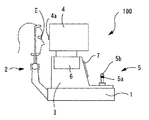
以下、本発明の実施形態を図面に基づいて説明する。図1は本実施形態に係る他覚式眼屈折力測定装置の外観構成図である。他覚式眼屈折力測定装置100は、基台1と、基台1に取り付けられた顔支持ユニット2と、基台1上に移動可能に設けられた移動台3と、移動台3に移動可能に設けられ、後述する光学系を収納する測定部4を備える。測定部4は、移動台3に設けられた駆動部6により、被検者眼Eに対して左右方向(X方向)、上下方向(Y方向)及び前後方向(Z方向)に移動される。移動台3は、ジョイスティック5の操作により、基台1上を左右方向及び前後方向に移動される。また、回転ノブ5aの回転操作により、測定部4は駆動部6の駆動で上下方向に移動される。ジョイスティック5の頂部には、測定開始スイッチ5bが設けられている。移動台3には、表示モニタ7が設けられている。
Hereinafter, embodiments of the present invention will be described with reference to the drawings. FIG. 1 is an external configuration diagram of an objective eye refractive power measurement apparatus according to this embodiment. The objective eye refracting
図2は、装置の光学系及び制御系の概略構成図である。眼屈折力測定光学系10は、被検者眼Eの瞳孔中心部を介して眼底Efにスポット状の測定指標を投影する投影光学系10aと、眼底Efから反射された眼底反射光を瞳孔周辺部を介してリング状に取り出し、二次元受光素子の撮像素子にリング状の眼底反射像を撮像させる受光光学系10bと、から構成される。
FIG. 2 is a schematic configuration diagram of an optical system and a control system of the apparatus. The eye refractive power measurement
投影光学系10aは、測定光学系10の光軸L1上に配置された測定光源11,リレーレンズ12,ホールミラー13,及び測定用対物レンズ14を含む。測定光源11は、正視眼の眼底Efと光学的に共役な位置関係に配置されている。また、ホールミラー13の開口は、被検者眼Eの瞳孔と光学的に共役な位置関係にされている。
The projection
受光光学系10bは、投影光学系10aの対物レンズ14、ホールミラー13が共用され、ホールミラー13の反射方向の光軸L1上に配置されたリレーレンズ16及び全反射ミラー17と、全反射ミラー17の反射方向の光軸上に配置された受光絞り18、コリメータレンズ19、リングレンズ20、及び二次元受光素子である撮像素子22を含む。受光絞り18及び撮像素子22は、眼底Efと光学的に共役な位置関係に配置されている。リングレンズ20は、透明平板状に円筒レンズがリング状に形成されたレンズ部と、リング状のレンズ部分以外が遮光された遮光部と、から構成されている。リングレンズ20は、対物レンズ14からコリメータレンズ19までの光学系を介して、被検者眼Eの瞳孔と光学的に共役な位置関係にされている。撮像素子22からの出力は制御部70に入力される。また、投影光学系10aの測定光源11,受光光学系10bのコリメータレンズ19、リングレンズ20、及び撮像素子22とは、移動機構23により一体的に光軸方向に移動される。なお、眼屈折力測定光学系10は、周知のものが使用可能である。
In the light receiving
対物レンズ14と被検者眼Eとの間には、視標呈示光学系30からの視標光束を被検者眼Eに導き、被検者眼Eの前眼部からの反射光を観察光学系50に導くダイクロイックミラー29が配置されている。ダイクロイックミラー29は、測定光学系10に用いられる測定光束の波長を透過する。
Between the
被検者眼Eの前眼部の前方には、アライメント指標投影光学系40が配置されている。アライメント指標投影光学系40は、被検者眼Eの角膜にリング指標を投影するリング指標投影光学系41と、角膜Ecに2つ輝点の無限遠指標を投影する指標投影光学系42と、を備える。指標投影光学系42は、観察光軸に対して左右対称に配置されている。リング指標投影光学系41は、被検者眼Eの前眼部を照明する前眼部照明としても用いられる。
An alignment index projection
観察光学系50は、ハーフミラー53の反射方向の光軸上に配置された撮像レンズ51及び二次元撮像素子52を備える。撮像素子52からの出力は、制御部70に入力される。これにより、被検者眼Eの前眼部像は二次元撮像素子52により撮像され、モニタ7上に表示される。また、観察光学系50は、アライメント指標投影光学系40により被検眼Eの角膜に形成されるアライメント指標像を検出する光学系を兼ね、制御部70によるアライメント指標像の位置検出に基づいてアライメント状態の適否が判定される。
The observation
視標呈示光学系30は、観察光学系50の対物レンズ39が共用され、ダイクロイックミラー29により光軸L1と同軸にされた光軸L2上に配置されたLED等の光源31,視標板32,リレーレンズ33、反射ミラー36を含む。また、視標呈示光学系30は被検者眼の屈折力を矯正するための屈折力矯正光学系と共用され、反射ミラー36とリレーレンズ33との間には乱視矯正光学系34が配置されている。
The optotype presenting
視標板32には、他覚屈折力測定時に被検者眼Eに雲霧を行うための固視標と、自覚屈折力測定時に使用される視力検査用視標を含む複数の視標32aが同心円上に配置されている。視力検査視標は、視力値毎の視標(視力値0.1、0.3、・・・、1.5)が用意されている。視標板32はモータ37によって回転され、視標32aが視標呈示光学系30の光軸L2上に切換え配置される。光源31によって照明された視標32aの視標光束は、リレーレンズ33からダイクロイックミラー29までの光学部材を介して被検者眼Eに向かう。
The
光源31及び視標板32(視標32a)は、モータ及びスライド機構からなる駆動機構38により光軸L2の方向に一体的に移動される。光源31及び視標32aが移動されることにより、視標の呈示位置(呈示距離)が遠用距離から近用距離まで光学的に変えられる。これにより、他覚屈折力測定時には被験者眼Eに雲霧が掛けられ、また、自覚屈折力測定時には被検者眼の球面屈折力が矯正される。すなわち、対物レンズ39、リレーレンズ33、光源31及び視標32aの移動により、球面度数の矯正光学系が構成される。球面度数の矯正光学系は、光軸方向に移動可能なリレーレンズを視標呈示光学系に追加する構成でも可能である。
The light source 31 and the target plate 32 (
乱視矯正光学系34は、焦点距離の等しい、2枚の正の円柱レンズ34a,34bから構成される。円柱レンズ34a,34bは、それぞれ回転機構35a、35bの駆動により、光軸L2を中心に各々独立して回転される。矯正光学系は、矯正レンズを視標呈示光学系の光路に出し入れする構成でも良い。
The astigmatism correction
制御部70は、撮像素子22に接続され、撮像素子22の出力に基づいて屈折力の演算処理を行う。また、制御部70は、撮像素子52、移動機構23、駆動機構38、モータ37、光源31、回転機構35a,35b、表示モニタ7、各種設定に用いられるスイッチ部80、測定開始スイッチ5b、画像メモリ75、駆動部6、プリンタ90等に接続されている。
The
図3は、スイッチ部80のスイッチ構成とモニタ7の表示の説明図である。図3のモニタ7の画面は、自覚の視力測定画面200の例である。スイッチ部80には8個のスイッチ80a〜80hが配置されている。各スイッチは、測定モードの選択によって切換えられるモニタ7の画面に応じて、各スイッチ信号の機能が切換えられる。
FIG. 3 is an explanatory diagram of the switch configuration of the
次に、以上のような構成を備える装置の測定動作について説明する。装置が起動されたときは、遠用での他覚屈折力測定モードに設定される。この場合、視標呈示光学系30の視標32aは、雲霧を掛けるための固視標(例えば、風景視標)が光路にセットされる。検者は被検者の顔を顔支持ユニット2に固定させ、被検者眼には測定部4の測定窓4a(図1参照)を介して測定部4内に配置された固視標を固視させる。
Next, the measurement operation of the apparatus having the above configuration will be described. When the device is activated, it is set to the objective power measurement mode for distance use. In this case, as the
他覚屈折力測定に際して、被検者眼Eの前眼部は、観察光学系50の撮像素子52により撮像され、モニタ7に前眼部像が映し出される。また、リング投影光学系41によって投影されたリング指標像及び指標投影光学系42によって投影された無限遠の指標像が撮像素子52により撮像される。これらのアライメント指標像もモニタ7に表示される。検者は、モニタ7上の前眼部像、アライメント視標像、レチクルを観察し、測定部4及び移動台3をジョイスティック5等の操作により移動して、被検者眼と装置の光学系とを所定の位置関係にアライメントする。アライメント完了後、測定開始スイッチ5bから測定開始信号が入力されると、屈折力測定が行われる。
When measuring objective refractive power, the anterior segment of the subject's eye E is imaged by the
図示を略すスイッチにより、自動アライメントモードが設定されている場合、撮像素子52により撮像されたアライメント指標像に基づき、制御部70によりアライメント状態が検出される。上下左右方向のアライメント状態は、リング投影光学系41によるリング指標像の中心位置と光軸との位置関係により検出される。作動距離方向のアライメント状態は、作動距離が変化しても指標投影光学系42による無限遠指標は変化せず、リング指標の所定経線方向の像間隔は変化するという特性を利用して、検出される(特開平6−46999号参照)。これらのアライメント指標像の検出結果に基づいて駆動部6が駆動され、アライメント状態が適正になるように測定部4が移動される。アライメントが完了すると、制御部70により自動的に測定開始信号のトリガが発せられ、遠用の屈折力測定が行われる。
When the automatic alignment mode is set by a switch (not shown), the
光源11から出射された測定光は、リレーレンズ12からダイクロイックミラー29までを介して眼底Efに投影され、眼底Ef上でスポット状の点光源像を形成する。眼底Ef上に形成された点光源像の光は、眼底により反射・散乱されて被検者眼Eを射出し、対物レンズ14、ホールミラー13、リレーレンズ16及び全反射ミラー17までの光学系を介して受光絞り18の開口上で再び集光され、コリメータレンズ19にて略平行光束(正視眼の場合)とされる。リングレンズ20によってリング状光束として取り出され、リング像として撮像素子22に受光される。
The measurement light emitted from the
遠用の他覚眼屈折力の測定においては、はじめに眼屈折力の予備測定が行われ、予備測定の結果に基づいて光源31及び固視標板32が光軸L2方向に移動されることにより、被検眼Eに対して雲霧がかけられる。その後、雲霧がかけられた被検眼に対して眼屈折力の本測定が行われる。本測定では、リングレンズ20によるリング像は撮像素子22に撮像され、撮像素子22からの出力信号は、画像メモリ75に画像データ(測定画像)として記憶される。その後、制御部70は、画像メモリ75に記憶されたリング像を画像解析して各経線方向の屈折力の値を求める。制御部70は、この屈折力に所定の処理を施すことによって遠用時での被検者眼のS(球面度数)、C(乱視度数)、A(乱視軸角度)の他覚値を得る。得られた遠用時での他覚値はメモリ75に記憶される。
In the measurement of the distance objective eye refractive power, first, preliminary measurement of eye refractive power is performed, and the light source 31 and the
なお、眼屈折力測定光学系10は、上記のようにリング状の指標像を利用する構成に限られず、眼底に測定指標を投影し、眼底からの反射光束を受光素子で受光し、少なくとも3経線方向の屈折力を得る光学系であれば良く、これは周知のものが使用可能である。
The eye refractive power measurement
図4は測定手順を示すフローチャートである。遠用での他覚屈折力測定が完了し、スイッチ80aが押されると、自覚の遠用視力測定(自覚屈折力測定)モードに切換えられ、モニタ7の画面は他覚屈折力測定モードの画面(図示せず)から図3の自覚の遠用視力測定画面200に切換えられる。制御部70は、遠用の他覚屈折力測定で得られた被検者眼の屈折度数(球面度数S、乱視度数C、乱視軸角度A)に基づいて矯正光学系を駆動し、被検者眼の屈折力誤差を矯正する。すなわち、遠用の他覚屈折力測定における球面度数Sに基づいて光源31及び視標板32が光軸L2方向に移動されて、球面屈折力Sの屈折力誤差が補正された状態にされる。また、乱視度数C及び乱視軸角度Aに基づいて乱視矯正光学系34が駆動され、乱視の屈折力誤差が補正された矯正状態とされる。また、制御部70はモータ37の回転制御によって視標板32を回転させ、光軸L2上に所要の視力値視標32aを配置させる(例えば、視力値0.8の視標)。
FIG. 4 is a flowchart showing the measurement procedure. When the objective power measurement for distance use is completed and the
以上のように、被検者眼に初期呈示視標が呈示されたら、検者は被検者の遠用視力測定を行う。視力値のUP及びDOWNする表示202a及び202bに対応したスイッチ80b及び80cが押されると、呈示される視力値視標が切換えられる。検者は、被検者の回答が正答の場合には、スイッチ80bを選択して1段階高い視力値の視標に切換える。一方、被検者の回答が誤答の場合にはスイッチ80cを選択して1段階低い視力値の視標に切換える。制御部70は、スイッチ80b又は80cによる視力値変更の信号入力に基づいて視標板32を回転させ、視標呈示光学系の光軸上の視力値視標32aを切換える。検者は、以上の手順を繰返すことで被検者が判読可能な限界の最高視力を求める。
As described above, when the initial presentation target is presented to the subject's eye, the examiner measures the distance vision of the subject. When the
他覚屈折力測定結果の矯正度数による遠用の最高視力値が得られたら、検者は被検者が最高視力値を得られる最もプラスよりの球面度数(最弱の度数)に調節するため、図3における球面度数を変更するUP/DOWNの表示204a及び204bに対応するスイッチ80f,80gの操作によって球面度数Sを変更する。スイッチ80fまたはスイッチ80eが選択されると、光源31及び視標板32が光軸L2方向に移動されて球面度数が変更される。これにより、最高視力が得られる最も弱い球面度数Sが決定され、眼鏡レンズ又はコンタクトレンズ等の遠用矯正度数を処方する際の参考値が得られる。
When the maximum vision value for distance using the correction power of the objective refractive power measurement result is obtained, the examiner adjusts the spherical power (the weakest power) from the most plus that allows the subject to obtain the highest vision value. The spherical power S is changed by operating the
次に、検者は呈示視標を近用距離に移動させた近用視力測定を行う。近用視力測定モードに移行する信号を入力するスイッチ80hが押されると、モニタ7には近用視力測定画面が表示される。図5は近用視力測定画面220の表示例である。近用視力測定画面220では、「ADD」表示221がスイッチ80dに対応され、近用視力測定時にはスイッチ80dにより加入度を付加させる指令信号が入力される。また、視力値UP/DOWNの表示202a及び202bがスイッチ80b及びスイッチ80cに対応される。また、加入度の度数を変更するUP/DOWNの表示224a及び224bがスイッチ80f及びスイッチ80gにそれぞれ対応される。また、画面220上の表示欄230には近用視力測定での近用距離が表示される。モニタ7の中央の表示欄231には、付加されている加入度が表示される。また、測定結果の表示欄240には、遠用での矯正度数(S、C、A)の値が表示される。
Next, the examiner performs near vision measurement by moving the presented visual target to the near distance. When the
前述のスイッチ80hにより、近用視力測定モードに切換えられると、駆動機構38の駆動により光源31及び視標板32が光軸L2上を移動され、視標板32による視標の呈示距離が所要の近用距離に移動される。例えば、視標は33cmの近用距離に相当する位置に設定される。33cmの近用距離は、屈折力換算で−3.0D(ディオプター)に相当する。制御部70は、遠用の矯正度数(遠用の他覚屈折力測定又は遠用の視力測定で決定された遠用矯正度数)の位置を基準にして、3.0D(ディオプター)分だけ近方に近づけた位置に視標板32を移動させる。すなわち、遠用の矯正度数に対して、−3.0D(ディオプター)の球面度数を加えた度数とされる。例えば、被検者眼の遠用球面度数が−2.0Dの場合には、これに−3.0Dが加えられ、33cmの近用距離での度数は、−5.0Dとされる。なお、近用視力測定モードへ移行するためのスイッチ80hが押された時点では、加入度が無し(0.00D)の状態である。なお、近用測定においても、遠用の他覚屈折力測定の結果に基づいて乱視矯正光学系が駆動されていることにより、乱視の屈折誤差が矯正された状態にされている。これにより、被検者眼は、乱視屈折誤差の影響を受けずに近用距離に呈示される視標を確認することができる。
When switched to the near vision measurement mode by the
検者は被検者の近用視力測定を行う。視力値がUP及びDOWNする表示202a及び202bに対応したスイッチ80b及び80cが押されると、呈示される視力値視標が切換わる。検者は、被検者の回答が正答の場合には、スイッチ80bを選択して1段階高い視力値の視標に切換える。一方、被検者の回答が誤答の場合にはスイッチ80cを選択して1段階低い視力値の視標に切換える。制御部70は、スイッチ80b又は80cによる視力値変更の信号入力に基づいて視標板32を回転させ、視標呈示光学系の光軸上の視力値視標32aを切換える。検者は、以上の手順を繰返すことで被検者が判読可能な限界の最高視力を求める。
The examiner measures the near vision of the subject. When the
制御部70は、遠用視力値と、近用視力値とに基づいて、加入度の初期値を推定する。例えば、遠用視力値が1.2であったとする。このとき、近用視力が0.5であった場合は、加入度の初期値を+1.0Dと設定し、0.2であった場合は、加入度の+2.0Dの初期値を設定する。なお、これは一例であり、加入度の初期値として用いる値は、実験的に求められた視力値と加入度の関係に基づく数値であってもよいし、遠用視力値と近用視力値とに基づいて、検者が経験的に設定できるようにしてもよい。また、視力値と加入度の関係から装置自体が自動で算出するようにしてもよい。このように、遠用視力値と近用視力値によって加入度の初期値を算出することで、加入度の測定時間を短縮することができる。
The
検者は、近用視力測定の結果から、加入度が必要かどうか判断する。遠用の視力値に比べ、近用の視力値が低下した場合や、近用距離に設定された視標は見え難いと被検者が答えた場合、状況に応じて加入度を加えた近用視力測定ステップに移行する。このとき、遠用視力値と近用視力値の差が小さい場合や、近用視力値が生活上問題のない数値である場合、眼の調節ラグ(本来の眼の合焦点位置が、焦点深度の深さと関連して、ピントの合う許容内で前方移動したり、後方移動したりする現象)を考慮して、制御部70は、加入度の必要性が無い可能性があることを検者に知らせるようにしても良い。例えば、近用視力が一定値(例えば、1.0)を下回る場合に、画面上に加入度が必要な旨のメッセージを表示させるようにしても良い。
The examiner determines whether the addition is necessary from the result of the near vision measurement. Compared to distance vision, when near vision decreases, or when the subject remarks that the target set at near distance is difficult to see, Move to the visual acuity measurement step. At this time, when the difference between the distance vision value and the near vision value is small, or when the near vision value is a numerical value that is not a problem in life, the eye adjustment lag (the focus position of the original eye is the depth of focus) In consideration of the depth of the image, the
「ADD」表示221に対応したスイッチ80dが押されると、制御部70は、矯正光学系(視標呈示光学系30)に加入度を付加すべく、駆動機構38を駆動し、近用距離(40cm)の位置を基準にして推定された加入度に相当する分だけ視標板32を光軸方向に移動させる。これにより、近用の加入度測定において、適切な加入度の初期値が簡単に設定され、加入度調整の測定時間が短縮される。なお、視標呈示光学系30に加入度が加えられると、表示231に加入度の値が表示される。
When the
検者は、被検者に対して加入度が加えられた状態の呈示視標の見え方を確認する。被検者が視標を見えやすいと回答した場合には、加入度は適切であると判断される。スイッチ80f及び80gが押されると、矯正光学系に加えられる加入度が0.25Dステップで増減される。これにより、検者は被検者眼に応じた加入度を微調整する。調整された加入度の値は、表示欄231に表示される。加入度の調整ができたら、検者は、スイッチ80b、80cにより呈示されている視標の視力値を切換え、被検者眼の限界の近用視力値を測定する。
The examiner confirms the appearance of the presentation target in a state where the addition degree is added to the subject. When the subject answers that the target is easy to see, it is determined that the addition is appropriate. When the
また、加入度の調整後、「ADD」表示221に対応したスイッチ80dが押される毎に、視標呈示光学系に加入度が加えられた状態と、加入度が除かれた状態と、に交互に切換えられる。加入度が除かれた状態は、乱視度数が矯正され、且つ球面度数が遠用での視力確認測定(又は遠用での眼屈折力の測定結果)に基づいて矯正された状態とされる。これにより、被検者は加入度の有無による近用視標の見え方の違いを比べることができ、加入度の必要性を知ることができる。このため、検者は被検者に対して近用距離での加入度の必要性について容易に説明できるようになる。
In addition, after the addition is adjusted, every time the
他覚の屈折力の測定結果、自覚の屈折力及び加入度等の測定結果は、精密な自覚測定の参考値として利用される。他覚屈折力測定装置により、これらの自覚の測定結果が得られることにより、精密な自覚測定での処方値の決定が行い易くなる。 The measurement results of the refractive power of the objective and the measurement results of the refractive power and addition of the subjective are used as reference values for precise subjective measurement. By obtaining the measurement results of these awareness by the objective refractive power measurement device, it becomes easy to determine the prescription value in the precise awareness measurement.
なお、本実施形態では加入度を加えた時点でのみ加えられた加入度を表示部に表示するような構成としたが、これに限定されない。加入度を加える必要がある場合、視力値に基づいて推定された加入度を予め表示部に表示する構成としてもよい。例えば、近用の視力測定時に視力0.8の視標を呈示しているのとき、加入度を付加するボタンを押した際に矯正光学系に付加される加入度を予め表示部231に表示してもよい。
In addition, in this embodiment, although it was set as the structure which displays the addition added only at the time of adding addition on a display part, it is not limited to this. When it is necessary to add a degree of addition, the degree of addition estimated based on the visual acuity value may be displayed on the display unit in advance. For example, when a visual acuity with a visual acuity of 0.8 is presented during near vision measurement, the addition added to the correction optical system when a button for adding addition is pressed is displayed on the
続いて、本実施形態の変容例を図面に基づいて説明する。図6は本実施形態の変容例に係わる検眼システムの外観構成図である。検眼システム500は、大別して、自覚的に被検者眼の視機能を検査するための検眼装置350と、被検者眼に遠用検査視標を呈示するための視標呈示装置330と、を備えている。本発明は、このような他覚式眼屈折力測定機能を持たない自覚式眼屈折力測定装置にも利用できる。以下に、より具体的な説明を加える。
Subsequently, a modification example of the present embodiment will be described with reference to the drawings. FIG. 6 is an external configuration diagram of an optometry system according to a modification example of the present embodiment. The
検眼装置350は、左右対称な一対のレンズ室ユニット352(左レンズ室ユニット352L,右レンズ室ユニット352R)と、レンズ室ユニット352を吊下げ支持する支持ユニット353と、を備えており、検眼テ−ブル301に固定されている。レンズ室ユニット352内には、球面レンズ、円柱レンズ、分散プリズム、ロータリプリズム、等の多数の光学素子が同一円周上に配置されているレンズディスクが回転可能に保持されており、レンズ室ユニット352に設けられている検査窓351(左検査窓351L,右検査窓351R)に光学素子が切換え配置される。検査窓351に配置される光学素子の切換え等は、入力手段(操作手段)であるコントローラ360の操作によって行われる。
The
支持ユニット353は、被検者の瞳孔間距離に合わせて左検査窓351Lと右検査窓351Rとの間隔を変えるためのレンズ室ユニット352の間隔調節機構(輻輳機構を含む)を備えている。また、支持ユニット353の略中央部(左レンズ室ユニット352Lと右レンズ室ユニット352Rとの間付近)には、近用検査視標呈示ユニット440をスライド可能に保持している近用棒420が固定されている。視標呈示ユニット440は、検査窓351からの距離が20〜70cm程度の間で移動される。本実施形態では、近用視力値検査又は近用両眼視機能検査の際、視標呈示ユニット440は、検査窓351からの距離が40cmの位置に置かれる。
The
視標呈示装置330は、遠用検査視標を呈示するディスプレイ(視標呈示部)331を備えている。視標呈示装置330は、リレーユニット306を介してコントローラ360と接続されており、ディスプレイ331に表示される視標の切換え等がコントローラ360の操作によって行われる。コントローラ360には、視力値検査を行うためのスイッチ、両眼視機能検査を行うためのスイッチ、等の種々のスイッチが設けられており、視標呈示装置330は、スイッチの操作に応じてディスプレイ331に遠用視力値検査視標又は遠用両眼視機能検査視標を呈示(表示)する。視標呈示装置330は、検眼装置350と略同じ高さに位置されると共に、検査に適した距離だけ検眼装置350から離れるように設置される。本実施形態では、検眼装置350と視標呈示装置330との間の距離(検査距離,設置距離)は、遠用検査に適した距離、例えば、5mとされている。
The
次に、本実施形態のコントローラ360について説明する。図7は、コントローラ360を上方から見た外観図である、コントローラ360は、呈示されている視標、検査内容、検査結果、等を表示する表示手段(出力手段)及び入力手段(操作手段)であるモニタ361、入力手段(操作手段)である各種スイッチが複数配置されているスイッチパネル362、等を備えている。モニタ361は、タッチパネル機能を有するカラーディスプレイであり、表示されている視標、検査項目、等を検者が選択(タッチ)することにより、装置を操作できる構成となっている。スイッチパネル362には、左右に回すことによって数値の増減、光学素子の切換え、等の信号を入力するためのダイヤルスイッチ363、球面度数S、乱視度数C、乱視軸角度A、瞳孔間距離PD、等のデータを変更するモードに切換えるためのモードスイッチ364、プログラム検査用のスタート/送りスイッチ365、表示モードを設定又は変更するためのメニュースイッチ366、等が設けられている。例えば、加入度測定においては、ダイヤルスイッチ363を回転させることにより、検査窓351に配置されている球面レンズの球面度数が増減される。
Next, the
図8は本変容例の検眼装置350を示す概略構成図である。レンズ室ユニット352にはレンズディスクを回転させるモータ318と、レンズディスクに配置された円柱レンズの回転機構、クロスシリンダレンズの回転機構等を回転させるモータ319が備わる。なお、円柱レンズの回転機構、クロスシリンダレンズの回転機構等には、特開2007−68574号公報に開示された技術が利用できる。
FIG. 8 is a schematic configuration diagram showing an
視標呈示ユニット440は、呈示窓442が設けられたケース441と、視標ディスク443と、ケース441を保持するホルダ444と、を備えている。複数種類の近用視標が表示(印字)された視標ディスク443は、ケース441中央のピン445を中心に回転可能にケース441内に収納されている。ケース441からは視標ディスク443の一部が露出しており、その露出部分を持って視標ディスク443を回転することにより、呈示窓442に所期する近用視標が配置される。ホルダ444は、視標呈示ユニット440を近用棒420に取り付けると共に、視標呈示ユニット440が近用棒420にスライド可能(近用棒420の軸方向に移動可能)に支持されるための機能を持つ。また、視標呈示ユニット440は、近用視標が単に印字された視標板であってもよいし、近用視標を表示する薄型の液晶ディスプレイのようなものであってもよい。
The
次に、検眼システム500の制御系について説明する。図9は、検眼システム500の制御系の概略ブロック図である。リレーユニット306の制御手段である制御部307に、検眼装置350の制御手段である制御部357、視標呈示装置330の制御手段である制御部337、コントローラ360の制御手段である制御部367、が接続されている。リレーユニット306は、検眼システ500において、データ、指令信号、等の入出力を行うためのユニットである。
Next, a control system of the
制御部337には、ディスプレイ331、視標(のデータ)等を記憶する記憶手段であるメモリ338、等が接続されている。制御部337には、コントローラ360(制御部367)から送信される指令信号をデコードするデコーダ等が備えられている。
The
制御部367には、モニタ361、ダイヤルスイッチ363等を含むスイッチパネルパネル362、検査プログラム、検査結果、等を記憶する記憶手段であるメモリ368、等が接続されている。本実施形態では、コントローラ360(制御部367)が、検眼システム500全体を統括・制御している。
The
モニタ361及びスイッチパネル362からの指令信号(光学素子の切換え指令信号、視標の切換え指令信号、等)は、制御部367から制御部37に送られる。制御部307は、受取った指令信号を制御部357と制御部337とに分配する。制御部357は、指令信号に基づいてモータ318、319等を駆動し、検査窓351に光学素子を配置する。制御部337は、指令信号に基づいてメモリ371から視標(のデータ)を読み出してディスプレイ331に表示させる。
Command signals (optical element switching command signal, target switching command signal, etc.) from the
以上のような構成を持つ自覚式眼屈折力測定装置を用いた、加入度の測定について説明する。加入度の測定前に完全矯正度数を求めた後、屈折矯正状態での遠用視力検査と近用視力検査を行うことが一般的である。被検眼の完全矯正度数を求める検査手順、検査手法等は、特開平11−19041号公報に開示された技術が利用できる。 The addition power measurement using the subjective eye refractive power measuring apparatus having the above configuration will be described. It is common to perform a distance vision test and a near vision test in a refractive correction state after obtaining the complete correction power before measuring the addition. The technique disclosed in Japanese Patent Application Laid-Open No. 11-19041 can be used for an examination procedure, an examination technique, and the like for obtaining the complete correction power of the eye to be examined.
屈折矯正状態での遠用視力検査を行うときは、被検者に検査窓351を覗かせ、ディスプレイ331に所要の視標を表示する。検者は、視標が識別できるか否か被検者に尋ね、回答の正誤によって適宜視標を切換えながら、最高の遠用視力値を測定する。
When performing a distance vision test in a state of refraction correction, the subject is allowed to look into the
屈折矯正状態での近用視力検査を行うときは、被検者に検査窓351を覗かせ、視標呈示ユニット440を検査窓351の前方に移動させ、所要の近用視標を呈示する。検者は指標が識別できるか否か被検者に尋ね、回答の正誤によって適宜指標を切換えながら、最高の近用視力値を測定する。
When performing a near vision test in a state of refraction correction, the subject is allowed to look into the
視力検査が終了すると、加入度の測定に移る。本変容例の検眼装置では、遠用視力値と近用視力値に基づいて、加入度の初期値を算出する。方法としては、例えば、遠用視力値と近用視力値の差が大きいときは、大きな加入度を初期値として設定し、逆に両者の差が小さいときは、小さな加入度を初期値として設定する。なお、加入度の初期値を算出する方法はこれに限らない。このように、加入度の初期値を算出することで、実施形態と同様に、加入度測定の測定時間を短縮することができる。 When the visual acuity test is completed, it moves to the measurement of the addition power. In the optometry apparatus of this modification example, the initial value of the addition is calculated based on the distance vision value and the near vision value. As a method, for example, when the difference between the distance vision value and the near vision value is large, a large addition is set as an initial value, and conversely, when the difference between the two is small, a small addition is set as an initial value. To do. Note that the method for calculating the initial value of the addition is not limited to this. Thus, by calculating the initial value of the addition, the measurement time of the addition measurement can be shortened as in the embodiment.
加入度を測定する際、検者は視標呈示ユニット440の視標を切換え、クロスグリッドチャートを被検眼に呈示する。また、加入度測定モードに移行すると、検査窓351には±0.5Dのクロスシリンダレンズが追加して配置される。このとき、クロスシリンダレンズのマイナス軸は90°に設定される。検者は、クロスグリッドの見え方を被検者に確認しながら、コントローラ360によって球面度数を調整する。クロスグリッドの縦線と横線が均等に見えるときの加入度が、加入度の最適値である。なお、加入度の測定は、クロスグリッド及びクロスシリンダを用いる測定に限らない。
When measuring the addition, the examiner switches the target of the
加入度の測定が終了すると、加入度を加えた状態での近用視力検査を行い、加入度を加えた状態での最高の近用視力値を測定する。 When the addition measurement is completed, the near vision test with the addition is performed, and the highest near vision value with the addition is measured.
なお、以上の説明においては、遠用視力値と近用視力値に基づいて、加入度の初期値を算出するとしたが、近用視力値のみに基づいて、加入度の初期値を推定値として算出してもよい。例えば、各近用視力値に対応して、加入度の初期値が切り換るようにすれば、装置の構成が簡単になる。 In the above description, the initial value of the add power is calculated based on the distance vision value and the near vision value. However, based on only the near vision value, the initial value of the add power is used as the estimated value. It may be calculated. For example, if the initial value of the addition power is switched corresponding to each near vision value, the configuration of the device is simplified.
また、近用視力値と、近用距離に視標が呈示された状態で取得された被検眼の近用眼屈折力値とに基づいて、加入度の初期値を算出するようにしてもよい。これにより、近用の眼屈折力を用いて加入度を初期値を算出する場合であっても、初期値の算出精度を向上させることができる。また、他覚的な加入度の測定結果が加味される。 Further, the initial value of the addition power may be calculated based on the near vision value and the near eye refractive power value of the eye to be examined acquired in a state where the visual target is presented at the near distance. . Thereby, even if it is a case where an initial value is calculated for addition power using near eye refractive power, the calculation accuracy of an initial value can be improved. In addition, objective addition measurement results are taken into account.
10 眼屈折力測定光学系
10a 投影光学系
10b 受光光学系
30 視標呈示光学系(矯正光学系)
70 制御部
80 スイッチ部
100 他覚式眼屈折力測定装置
220 近用視力測定画面
221 「ADD」表示
231 表示欄
250 視標チャート表示
DESCRIPTION OF
70
Claims (1)
視力検査用視標と被検眼の間に配置され、被検者眼の球面屈折力を矯正する矯正光学系と、
被検眼の加入度の初期値を推定する加入度推定手段と、
前記矯正光学系を駆動させ、前記加入度推定手段によって推定された前記初期値に対応する加入度を付加する制御手段と、を備え、
前記加入度推定手段は、前記視力検査用視標を遠用距離から呈示することによって取得された被検眼の遠用視力と、前記視力検査用視標を近用距離から呈示することによって取得された被検眼の近用視力との差が大きい場合、前記差が小さい場合に比べて大きな前記初期値を推定することを特徴とする眼屈折力測定装置。 An eye refractive power measuring apparatus for measuring the eye refractive power of a subject eye,
A correction optical system that is arranged between the eyesight test target and the eye to be examined and corrects the spherical refractive power of the eye of the subject;
Addition power estimation means for estimating an initial value of the addition power of the eye to be examined;
Control means for driving the correction optical system and adding an addition corresponding to the initial value estimated by the addition estimation means ;
The addition degree estimation means is obtained by presenting the distance vision of the eye to be examined obtained by presenting the eyesight test target from a distance and the eyesight test target from a near distance. An eye refractive power measurement apparatus characterized in that when the difference from near vision of the subject eye is large, the initial value is estimated to be larger than when the difference is small .
Priority Applications (1)
| Application Number | Priority Date | Filing Date | Title |
|---|---|---|---|
| JP2012190856A JP6057061B2 (en) | 2012-08-31 | 2012-08-31 | Eye refractive power measuring device |
Applications Claiming Priority (1)
| Application Number | Priority Date | Filing Date | Title |
|---|---|---|---|
| JP2012190856A JP6057061B2 (en) | 2012-08-31 | 2012-08-31 | Eye refractive power measuring device |
Publications (3)
| Publication Number | Publication Date |
|---|---|
| JP2014045924A JP2014045924A (en) | 2014-03-17 |
| JP2014045924A5 JP2014045924A5 (en) | 2015-10-15 |
| JP6057061B2 true JP6057061B2 (en) | 2017-01-11 |
Family
ID=50606223
Family Applications (1)
| Application Number | Title | Priority Date | Filing Date |
|---|---|---|---|
| JP2012190856A Active JP6057061B2 (en) | 2012-08-31 | 2012-08-31 | Eye refractive power measuring device |
Country Status (1)
| Country | Link |
|---|---|
| JP (1) | JP6057061B2 (en) |
Families Citing this family (2)
| Publication number | Priority date | Publication date | Assignee | Title |
|---|---|---|---|---|
| JP7126661B2 (en) * | 2017-05-24 | 2022-08-29 | 国立大学法人大阪大学 | Ophthalmic device and method of operating the ophthalmic device |
| JP7283391B2 (en) * | 2017-12-04 | 2023-05-30 | 株式会社ニデック | eye refractive power measuring device |
Family Cites Families (2)
| Publication number | Priority date | Publication date | Assignee | Title |
|---|---|---|---|---|
| JP5342211B2 (en) * | 2008-11-04 | 2013-11-13 | 株式会社ニデック | Eye refractive power measuring device |
| DE102009004866B4 (en) * | 2009-01-16 | 2010-11-04 | Carl Zeiss Vision Gmbh | Method and device for determining the individually required addition of a visual aid |
-
2012
- 2012-08-31 JP JP2012190856A patent/JP6057061B2/en active Active
Also Published As
| Publication number | Publication date |
|---|---|
| JP2014045924A (en) | 2014-03-17 |
Similar Documents
| Publication | Publication Date | Title |
|---|---|---|
| JP5248926B2 (en) | Eye refractive power measuring device | |
| JP5342211B2 (en) | Eye refractive power measuring device | |
| CN106963335B (en) | Subjective eye examination device | |
| JP6951054B2 (en) | Subjective optometry device | |
| KR20130072135A (en) | Ophthalmologic apparatus and ophthalmologic control method, and storage medium | |
| US10470658B2 (en) | Optometry apparatus and optometry program | |
| JP2018047049A (en) | Subjective optometer and subjective optometric program | |
| JP6922338B2 (en) | Subjective optometry device | |
| JP6853496B2 (en) | Optometry device and optometry program | |
| JP5554485B2 (en) | Eye refractive power measuring device | |
| JP2017063978A (en) | Ophthalmologic apparatus | |
| JP2019063265A (en) | Subjective optometry apparatus | |
| CN110786822A (en) | Subjective refraction device and subjective refraction program | |
| JP6853495B2 (en) | Subjective optometry device and subjective optometry program | |
| JP6057061B2 (en) | Eye refractive power measuring device | |
| JP2018143553A (en) | Subjective optometry apparatus | |
| CN107788946B (en) | Subjective optometry device and subjective optometry program | |
| JP7098880B2 (en) | Subjective optometry device and subjective optometry program | |
| JP6064445B2 (en) | Eye refractive power measuring device | |
| JP2018143554A (en) | Subjective optometry apparatus | |
| JP2017063979A (en) | Ophthalmologic apparatus and ophthalmologic measuring method | |
| JP6766342B2 (en) | Awareness optometry device | |
| JP4628795B2 (en) | Optometry equipment | |
| JP7443831B2 (en) | Optometry systems, optometry controllers, and optometry programs | |
| JP2018171140A (en) | Subjective optometric apparatus and subjective optometric program |
Legal Events
| Date | Code | Title | Description |
|---|---|---|---|
| A521 | Request for written amendment filed |
Free format text: JAPANESE INTERMEDIATE CODE: A523 Effective date: 20150827 |
|
| A621 | Written request for application examination |
Free format text: JAPANESE INTERMEDIATE CODE: A621 Effective date: 20150827 |
|
| A977 | Report on retrieval |
Free format text: JAPANESE INTERMEDIATE CODE: A971007 Effective date: 20160518 |
|
| A131 | Notification of reasons for refusal |
Free format text: JAPANESE INTERMEDIATE CODE: A131 Effective date: 20160524 |
|
| A521 | Request for written amendment filed |
Free format text: JAPANESE INTERMEDIATE CODE: A523 Effective date: 20160725 |
|
| TRDD | Decision of grant or rejection written | ||
| A01 | Written decision to grant a patent or to grant a registration (utility model) |
Free format text: JAPANESE INTERMEDIATE CODE: A01 Effective date: 20161109 |
|
| A61 | First payment of annual fees (during grant procedure) |
Free format text: JAPANESE INTERMEDIATE CODE: A61 Effective date: 20161122 |
|
| R150 | Certificate of patent or registration of utility model |
Ref document number: 6057061 Country of ref document: JP Free format text: JAPANESE INTERMEDIATE CODE: R150 |
|
| R250 | Receipt of annual fees |
Free format text: JAPANESE INTERMEDIATE CODE: R250 |
|
| R250 | Receipt of annual fees |
Free format text: JAPANESE INTERMEDIATE CODE: R250 |
|
| R250 | Receipt of annual fees |
Free format text: JAPANESE INTERMEDIATE CODE: R250 |
|
| R250 | Receipt of annual fees |
Free format text: JAPANESE INTERMEDIATE CODE: R250 |
|
| R250 | Receipt of annual fees |
Free format text: JAPANESE INTERMEDIATE CODE: R250 |