JP7098880B2 - Subjective optometry device and subjective optometry program - Google Patents
Subjective optometry device and subjective optometry program Download PDFInfo
- Publication number
- JP7098880B2 JP7098880B2 JP2017069850A JP2017069850A JP7098880B2 JP 7098880 B2 JP7098880 B2 JP 7098880B2 JP 2017069850 A JP2017069850 A JP 2017069850A JP 2017069850 A JP2017069850 A JP 2017069850A JP 7098880 B2 JP7098880 B2 JP 7098880B2
- Authority
- JP
- Japan
- Prior art keywords
- eye
- inspected
- optical
- subjective
- measurement
- Prior art date
- Legal status (The legal status is an assumption and is not a legal conclusion. Google has not performed a legal analysis and makes no representation as to the accuracy of the status listed.)
- Active
Links
Images

Description
本開示は、被検眼の光学特性を自覚的に測定する自覚式検眼装置及び自覚式検眼プログラムに関する。 The present disclosure relates to a subjective optometry device and a subjective optometry program that subjectively measure the optical characteristics of an eye to be inspected.
従来、自覚式検眼装置としては、例えば、屈折度の矯正が可能な矯正光学系を被検者の眼前に個別に配置し、矯正光学系を介して検査視標を被検眼の眼底へ投光するものが知られている(特許文献1参照)。検者は、被検者の応答を受けその視標が被検者に適正に見えるまで矯正光学系の調節を行って矯正値を求め、この矯正値に基づいて被検眼の屈折力を測定する。また、例えば、自覚式検眼装置としては、矯正光学系を介した検査視標が像を被検者の眼前に形成し、矯正光学系を眼前に配置することなく、被検眼の屈折力を測定するものが知られている(特許文献2)。 Conventionally, as a subjective optometry device, for example, a correction optical system capable of correcting the refractive index is individually arranged in front of the subject's eyes, and an examination target is projected onto the fundus of the subject's eye via the correction optical system. Is known (see Patent Document 1). In response to the subject's response, the examiner adjusts the correction optical system until the target looks appropriate to the subject, obtains the correction value, and measures the refractive power of the subject's eye based on this correction value. .. Further, for example, in a subjective optometry device, an inspection target via a corrective optical system forms an image in front of the subject's eyes, and the refractive power of the subject's eye is measured without arranging the corrective optical system in front of the eyes. Is known (Patent Document 2).
ところで、自覚式検眼装置において、被検眼の光学特性を自覚的に測定している間に、被検眼の調節機能が働く等の原因によって、被検眼の光学特性が変化することがある。このような光学特性が変化してしまった状態で、自覚的な測定を行った場合に、被検眼の光学特性を精度よく測定することは困難であった。 By the way, in the subjective optometry device, the optical characteristics of the optometry subject may change due to a cause such as the accommodation function of the optometry object working while the optical characteristics of the optometry object are being subjectively measured. It has been difficult to accurately measure the optical characteristics of the eye to be inspected when subjective measurement is performed in a state where such optical characteristics have changed.
本開示は、上記問題点を鑑み、被検眼の光学特性を自覚的に測定する際に、被検眼の光学特性を精度よく測定することができる自覚式検眼装置を提供することを技術課題とする。 In view of the above problems, it is a technical subject of the present disclosure to provide a subjective optometry apparatus capable of accurately measuring the optical characteristics of an optometry subject when the optical characteristics of the optometry object are subjectively measured. ..
上記課題を解決するために、本発明は以下のような構成を備えることを特徴とする。 In order to solve the above problems, the present invention is characterized by having the following configurations.
(1) 本開示の第1態様に係る自覚式検眼装置は、視標光束を被検眼に向けて投影する投光光学系の光路中に配置され、前記視標光束の光学特性を変化する矯正光学系と、を有し、前記被検眼の光学特性を自覚的に測定する自覚式測定手段を備え、被検眼の光学特性を自覚的に測定する自覚式検眼装置であって、被検眼の眼底に測定光を出射し、その反射光を受光する測定光学系を有し、前記被検眼の光学特性を他覚的に測定する他覚式測定手段と、前記自覚式測定手段によって前記被検眼の光学特性を自覚的に測定している間に、前記他覚式測定手段によって前記被検眼の光学特性を他覚的に測定する制御手段と、を備え、前記制御手段は、前記他覚式測定手段によって前記被検眼の光学特性を他覚的に測定して第1光学特性を取得するとともに、前記自覚式測定手段によって前記被検眼の光学特性を自覚的に測定している間に、前記他覚式測定手段によって前記被検眼の光学特性を他覚的に測定して第2光学特性を取得し、前記第1光学特性及び前記第2光学特性に基づく調節情報を取得する取得手段と、前記調節情報を出力する出力手段と、を備え、前記矯正光学系が前記測定光学系の光路中に配置され、前記矯正光学系による矯正情報に基づいて、前記他覚式測定手段によって前記被検眼を他覚的に測定して得られた測定結果を補正する第2補正手段を備えることを特徴する。
(2) 本開示の第2態様に係る自覚式検眼プログラムは、被検眼の眼底に測定光を出射し、その反射光を受光する測定光学系を有し、前記被検眼の光学特性を他覚的に測定する他覚式測定手段と、視標光束を被検眼に向けて投影する投光光学系と、前記投光光学系の光路中であって、前記測定光学系の光路中に配置され、前記視標光束の光学特性を変化する矯正光学系と、を有し、前記被検眼の光学特性を自覚的に測定する自覚式測定手段と、を備え、被検眼の光学特性を自覚的に測定する自覚式検眼装置において用いられる自覚式検眼プログラムであって、前記自覚式検眼装置のプロセッサによって実行されることで、前記自覚式測定手段によって前記被検眼の光学特性を自覚的に測定している間に、前記他覚式測定手段によって前記被検眼の光学特性を他覚的に測定する制御ステップであって、前記他覚式測定手段によって前記被検眼の光学特性を他覚的に測定して第1光学特性を取得するとともに、前記自覚式測定手段によって前記被検眼の光学特性を自覚的に測定している間に、前記他覚式測定手段によって前記被検眼の光学特性を他覚的に測定して第2光学特性を取得する制御ステップと、前記第1光学特性及び前記第2光学特性に基づく調節情報を取得する取得ステップと、前記調節情報を出力する出力ステップと、前記矯正光学系による矯正情報に基づいて、前記他覚式測定手段によって前記被検眼を他覚的に測定して得られた測定結果を補正する第2補正ステップと、を前記自覚式検眼装置に実行させることを特徴とする。
(1 ) The subjective eye examination device according to the first aspect of the present disclosure is arranged in the optical path of the projection optical system that projects the target light beam toward the eye to be inspected, and corrects the optical property of the target light beam. It is a subjective eye inspection device that has an optical system, has a subjective measurement means for subjectively measuring the optical characteristics of the eye to be inspected, and subjectively measures the optical characteristics of the eye to be inspected, and is a fundus of the eye to be inspected. It has a measurement optical system that emits measurement light and receives the reflected light, and objectively measures the optical characteristics of the eye to be inspected by an objective measurement means and a subjective measurement means of the eye to be inspected. The control means includes a control means for objectively measuring the optical characteristics of the eye to be inspected by the objective measurement means while the optical characteristics are subjectively measured, and the control means is the objective measurement. The other An acquisition means for objectively measuring the optical characteristics of the eye to be inspected by a sensory measuring means to acquire the second optical characteristics, and acquiring adjustment information based on the first optical characteristics and the second optical characteristics, and the above-mentioned An output means for outputting adjustment information is provided, the correction optical system is arranged in the optical path of the measurement optical system, and the eye to be inspected is measured by the objective measurement means based on the correction information by the correction optical system. It is characterized by comprising a second correction means for correcting the measurement result obtained by objectively measuring.
(2 ) The subjective eye examination program according to the second aspect of the present disclosure has a measurement optical system that emits measurement light to the fundus of the eye to be inspected and receives the reflected light, and objectively perceives the optical characteristics of the eye to be inspected. Objective measuring means for measuring objectively, a projection optical system for projecting a target light beam toward the eye to be inspected, and an optical path of the projection optical system, which are arranged in the optical path of the measurement optical system. A correction optical system that changes the optical characteristics of the target light beam, and a subjective measuring means for subjectively measuring the optical characteristics of the eye to be inspected are provided, and the optical characteristics of the eye to be inspected are subjectively measured. It is a subjective eye examination program used in the subjective eye examination device to measure, and by being executed by the processor of the subjective eye examination device, the optical characteristics of the eye to be inspected are subjectively measured by the subjective measurement means. While this is a control step for objectively measuring the optical characteristics of the eye to be inspected by the objective measuring means, the optical characteristics of the eye to be inspected are objectively measured by the objective measuring means. While acquiring the first optical characteristic and subjectively measuring the optical characteristic of the eye to be inspected by the subjective measuring means, the objective measuring means objectively measures the optical characteristic of the eye to be inspected. A control step for acquiring the second optical characteristic by measuring the optics, an acquisition step for acquiring the adjustment information based on the first optical characteristic and the second optical characteristic, an output step for outputting the adjustment information, and the correction optics. To cause the subjective eye examination device to perform a second correction step of objectively measuring the eye to be inspected by the objective measurement means and correcting the measurement result obtained based on the correction information by the system. It is characterized by.
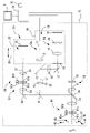
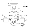
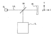
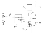
以下、典型的な実施形態の1つについて、図面を参照して説明する。図1~図7は本実施形態に係る自覚式検眼装置及び自覚式検眼プログラムについて説明するための図である。なお、以下の説明においては、自覚式検眼装置を例に挙げて説明する。なお、以下の<>にて分類された項目は、独立又は関連して利用されうる。 Hereinafter, one of the typical embodiments will be described with reference to the drawings. 1 to 7 are diagrams for explaining the subjective optometry device and the subjective optometry program according to the present embodiment. In the following description, a subjective optometry device will be described as an example. The items classified by <> below can be used independently or in relation to each other.
なお、本開示においては、本実施形態に記載した装置に限定されない。例えば、下記実施形態の機能を行う端末制御ソフトウェア(プログラム)をネットワーク又は各種記憶媒体等を介して、システムあるいは装置に供給する。そして、システムあるいは装置の制御装置(例えば、CPU等)がプログラムを読み出し、実行することも可能である。 The present disclosure is not limited to the apparatus described in the present embodiment. For example, terminal control software (program) that performs the functions of the following embodiments is supplied to a system or an apparatus via a network or various storage media. Then, a system or a control device of the device (for example, a CPU or the like) can read and execute the program.
なお、以下の説明においては、自覚式検眼装置の奥行き方向(被検者の測定の際の被検者の前後方向)をZ方向、奥行き方向に垂直(被検者の測定の際の被検者の左右方向)な平面上の水平方向をX方向、鉛直方向(被検者の測定の際の被検者の上下方向)をY方向として説明する。なお、以下符号に付されるR、Lはそれぞれ右眼用、左眼用を示すものとする。 In the following description, the depth direction of the subjective eye examination device (the front-back direction of the subject when measuring the subject) is perpendicular to the Z direction and the depth direction (the subject when measuring the subject). The horizontal direction on the plane (horizontal direction of the subject) will be described as the X direction, and the vertical direction (vertical direction of the subject when measuring the subject) will be described as the Y direction. It should be noted that R and L attached to the following reference numerals indicate those for the right eye and those for the left eye, respectively.
<概要>
例えば、本実施形態における自覚式検眼装置(例えば、自覚式検眼装置1)は、自覚式測定手段を備える。また、例えば、自覚式検眼装置は他覚式測定手段を備える。また、例えば、制御手段(例えば、制御部70)を備える。
<Overview>
For example, the subjective optometry device (for example, the subjective optometry device 1) in the present embodiment includes a subjective measurement means. Further, for example, the subjective optometry device includes objective measuring means. Further, for example, a control means (for example, a control unit 70) is provided.
<自覚式測定手段>
例えば、自覚式測定手段は、被検眼の光学特性を自覚的に測定する。例えば、自覚的に測定される被検眼の光学特性としては、眼屈折力(例えば、球面度数、乱視度数、乱視軸角度等)、コントラスト感度、両眼視機能(例えば、斜位量、立体視機能等)等が挙げられる。
<Awareness measuring means>
For example, the subjective measuring means subjectively measures the optical characteristics of the eye to be inspected. For example, the optical characteristics of the eye to be measured that are subjectively measured include optical power (for example, spherical power, astigmatic power, astigmatic axis angle, etc.), contrast sensitivity, binocular vision function (for example, oblique amount, stereoscopic vision, etc.). Functions, etc.), etc.
例えば、自覚式測定手段は、投光光学系(例えば、投光光学系30)を備える。また、例えば、投光光学系は、視標光束を被検眼に向けて投影する。また、例えば、自覚式測定手段は、矯正光学系(例えば、矯正光学系60、自覚式測定光学系25)を備える。例えば、矯正光学系は、投光光学系の光路中に配置され、視標光束の光学特性を変化させる。なお、投光光学系については、自覚式測定手段において、一体的に設けられている必要は無く、別途、投光光学系を備える装置が設けられる構成であってもよい。すなわち、本実施形態における自覚式測定手段としては、少なくとも矯正光学系を備える構成であってもよい。
For example, the subjective measuring means includes a floodlight optical system (for example, a floodlight optical system 30). Further, for example, the projection optical system projects the target luminous flux toward the eye to be inspected. Further, for example, the subjective measurement means includes a correction optical system (for example, a correction
<投光光学系>
例えば、投光光学系は、視標光束を投影する光源を有する。また、例えば、投光光学系は、視標光束を投影する光源から投影された視標光束を被検眼に向けて導光する少なくとも1つ以上の光学部材等を有してもよい。
<Light projection optical system>
For example, a floodlight optical system has a light source that projects a luminous flux. Further, for example, the projection optical system may have at least one or more optical members that guide the target luminous flux projected from the light source that projects the target luminous flux toward the eye to be inspected.
例えば、視標光束を投影する光源としては、ディスプレイ(例えば、ディスプレイ31)を用いる構成であってもよい。例えば、ディスプレイとしては、LCD(Liquid Crystal Display)や有機EL(Electro Luminescence)等が用いられる。例えば、ディスプレイには、ランドルト環視標等の検査視標等が表示される。 For example, a display (for example, display 31) may be used as the light source for projecting the luminous flux. For example, as a display, an LCD (Liquid Crystal Display), an organic EL (Electro Luminescence), or the like is used. For example, an inspection target such as a Randold ring optotype is displayed on the display.
例えば、視標光束を投影する光源としては、光源とDMD(Digital Micromirror Device)を用いてもよい。一般的にDMDは反射率が高く、明るい。そのため、偏光を用いる液晶ディスプレイを用いた場合と比べ、視標光束の光量を維持できる。 For example, a light source and a DMD (Digital Micromirror Device) may be used as the light source for projecting the luminous flux. Generally, DMD has high reflectance and is bright. Therefore, the amount of light of the target luminous flux can be maintained as compared with the case of using a liquid crystal display using polarization.
例えば、視標光束を投影する光源としては、視標呈示用可視光源と、視標板と、を有する構成であってもよい。この場合、例えば、視標板は、回転可能なディスク板であり、複数の視標を持つ。複数の視標は、例えば、自覚測定時に使用される視力検査用視標、等を含んでいる。例えば、視力検査用視標は、視力値毎の視標(視力値0.1、0.3、・・・、1.5)が用意されている。例えば、視標板はモータ等によって回転され、視標は、被検眼に視標光束が導光される光路上で切換え配置される。もちろん、視標光束を投影する光源としては、上記構成以外の光源を用いてもよい。 For example, the light source for projecting the luminous flux may be configured to include a visible light source for presenting an optotype and an optotype plate. In this case, for example, the optotype is a rotatable disc plate and has a plurality of optotypes. The plurality of optotypes include, for example, a visual acuity test optotype used at the time of subjective measurement. For example, as a visual acuity test target, visual acuity values (visual acuity values 0.1, 0.3, ..., 1.5) are prepared for each visual acuity value. For example, the optotype plate is rotated by a motor or the like, and the optotypes are switched and arranged on an optical path in which the optotype luminous flux is guided to the eye to be inspected. Of course, as the light source for projecting the luminous flux, a light source other than the above configuration may be used.
<矯正光学系>
例えば、矯正光学系は、視標光束の光学特性(例えば、球面度数、円柱度数、円柱軸、偏光特性、及び収差量、等の少なくともいずれか)を変更する構成であればよい。例えば、視標光束の光学特性を変更する構成として、光学素子を制御する構成であってもよい。例えば、光学素子としては、球面レンズ、円柱レンズ、クロスシリンダレンズ、ロータリープリズム、波面変調素子等の少なくともいずれかを用いる構成であってもよい。もちろん、例えば、光学素子としては、上記記載の光学素子とは異なる光学素子を用いるようにしてもよい。
<Correcting optical system>
For example, the correction optical system may be configured to change the optical characteristics of the visual target light flux (for example, at least one of spherical power, cylindrical power, cylindrical axis, polarization characteristics, aberration amount, and the like). For example, the optical element may be controlled as a configuration for changing the optical characteristics of the luminous flux. For example, the optical element may be configured to use at least one of a spherical lens, a cylindrical lens, a cross cylinder lens, a rotary prism, a wavefront modulation element, and the like. Of course, for example, as the optical element, an optical element different from the above-mentioned optical element may be used.
例えば、矯正光学系は、被検者眼に対する視標の呈示位置(呈示距離)が光学的に変えられることにより、被検眼の球面度数が矯正される構成であってもよい。この場合、例えば、視標の呈示位置(呈示距離)が光学的に変更する構成としては、光源(例えば、ディスプレイ)を光軸方向に移動させる構成であってもよい。また、この場合、例えば、光路中に配置された光学素子(例えば、球面レンズ)を光軸方向に移動させる構成であってもよい。もちろん、矯正光学系は、光学素子を制御する構成と光路中に配置された光学素子を光軸方向に移動させる構成と組み合わせた構成であってもよい。 For example, the correction optical system may have a configuration in which the spherical power of the subject's eye is corrected by optically changing the presentation position (presentation distance) of the optotype with respect to the subject's eye. In this case, for example, the configuration in which the presentation position (presentation distance) of the optotype is optically changed may be such that the light source (for example, the display) is moved in the optical axis direction. Further, in this case, for example, an optical element (for example, a spherical lens) arranged in the optical path may be configured to move in the optical axis direction. Of course, the correction optical system may have a configuration in which a configuration for controlling the optical element and a configuration for moving the optical element arranged in the optical path in the optical axis direction are combined.
例えば、矯正光学系としては、被検眼の眼前に配置される光学素子を切り換えて配置する検眼ユニット(フォロプタ)であってもよい。例えば、検眼ユニットは、複数の光学素子が同一円周上に配置されたレンズディスクと、レンズディスクを回転させるための駆動手段と、を有し、駆動手段(例えば、モータ)の駆動により光学素子を電気的に切り換える構成であってもよい。 For example, the corrective optical system may be an optometry unit (folopter) in which optical elements arranged in front of the eye to be inspected are switched and arranged. For example, the optometry unit has a lens disk in which a plurality of optical elements are arranged on the same circumference and a driving means for rotating the lens disk, and the optical element is driven by the driving means (for example, a motor). May be configured to be electrically switched.
例えば、矯正光学系としては、投光光学系から視標光束を被検眼に向けて導光するための光学部材と、視標呈示手段と、間に光学素子を配置して、光学素子を制御することによって、視標光束の光学特性を変更する構成であってもよい。すなわち、矯正手段としては、ファントムレンズ屈折計(ファントム矯正光学系)の構成であってもよい。この場合、例えば、矯正光学系によって矯正された視標光束が光学部材を介して被検眼に導光される。 For example, as a correction optical system, an optical element is arranged between an optical member for guiding a target light beam from a projection optical system toward an eye to be inspected and a target display means to control the optical element. By doing so, the optical characteristics of the optotype light beam may be changed. That is, as the correction means, a phantom lens refractometer (phantom correction optical system) may be configured. In this case, for example, the target luminous flux corrected by the correction optical system is guided to the eye to be inspected via the optical member.
<他覚式測定手段>
例えば、本実施形態における自覚式検眼装置は、他覚式測定手段を備える。例えば、他覚式測定手段は、被検眼の光学特性を他覚的に測定する。例えば、他覚的に測定される被検眼の光学特性としては、眼屈折力(例えば、球面度数、乱視度数、乱視軸角度等)、偏光特性、水晶体の厚み情報等が挙げられる。なお、本実施形態においては、被検眼の眼屈折力を測定する他覚式測定手段を例に挙げて説明する。なお、例えば、他覚式測定手段は、被検眼の眼底に測定光を出射し、その反射光を受光する測定光学系(例えば、他覚式測定光学系10)を備える。例えば、他覚的に測定される被検眼の光学特性としては、他覚式測定手段によって撮像された撮像結果(撮像画像)及び撮像結果を解析処理することによって取得されるパラメータの少なくともいずれかであってもよい。すなわち、他覚的に測定される被検眼の光学特性としては、他覚式測定手段によって撮像される撮像結果に基づくものであればよい。
<Objective measuring means>
For example, the subjective optometry device in the present embodiment includes objective measuring means. For example, the objective measuring means objectively measures the optical characteristics of the eye to be inspected. For example, objectively measured optical characteristics of the eye to be inspected include optical power (for example, spherical power, astigmatic power, astigmatic axis angle, etc.), polarization characteristics, lens thickness information, and the like. In this embodiment, an objective measuring means for measuring the refractive power of the eye to be inspected will be described as an example. For example, the objective measurement means includes a measurement optical system (for example, the objective measurement optical system 10) that emits the measurement light to the fundus of the eye to be inspected and receives the reflected light. For example, the optical characteristics of the eye to be measured objectively include at least one of the imaging result (imaging image) captured by the objective measuring means and the parameter acquired by analyzing the imaging result. There may be. That is, the optical characteristics of the eye to be measured objectively may be based on the image pickup result captured by the objective measurement means.
例えば、他覚式測定手段は、左右一対に設けられた右被検眼用測定光学系と左被検眼用測定光学系を有するようにしてもよい。この場合、例えば、右被検眼用測定光学系と左被検眼用測定光学系左右の測定を略同時に実行するようにしてもよい。また、この場合、例えば、右被検眼用測定光学系と左被検眼用測定光学系左右の測定を異なるタイミングで実施するようにしてもよい。例えば、異なるタイミングは、右被検眼用測定光学系と左被検眼用測定光学系の一方の測定光学系の測定が完了したタイミングであってもよい。また、例えば、異なるタイミングは、右被検眼用測定光学系と左被検眼用測定光学系の一方の測定光学系の測定を実施している間であってもよい。 For example, the objective measurement means may have a pair of left and right measurement optical systems for the right eye to be inspected and a measurement optical system for the left eye to be inspected. In this case, for example, the measurement optical system for the right eye to be inspected and the measurement optical system for the left eye to be inspected may be measured at substantially the same time. Further, in this case, for example, the measurement optical system for the right eye to be inspected and the measurement optical system for the left eye to be inspected may be measured at different timings. For example, the different timing may be the timing at which the measurement of one of the measurement optical system for the right eye to be inspected and the measurement optical system for the left eye to be inspected is completed. Further, for example, the different timing may be performed while the measurement of one of the measurement optical system for the right eye to be inspected and the measurement optical system for the left eye to be inspected is being carried out.
また、例えば、他覚式測定手段は、1つの測定光学系によって、左右被検眼の測定が行われるようにしてもよい。この場合、例えば、一方の被検眼の眼底に測定光を出射して被検眼の測定を行うとともに、一方の眼の測定が完了した場合に、他方の被検眼の眼底に測定光が出射できるように調整を行い、他方の被検眼の測定を行う構成としてもよい。 Further, for example, the objective measuring means may allow the measurement of the left and right eyes to be measured by one measuring optical system. In this case, for example, the measurement light is emitted to the fundus of one eye to be inspected to measure the eye to be inspected, and when the measurement of one eye is completed, the measurement light can be emitted to the fundus of the other eye to be inspected. It may be configured to make adjustments and measure the other eye to be inspected.
<測定光学系>
例えば、測定光学系は、被検者眼眼底に向けて光源から測定光を投光する投光光学系と、測定光の眼底での反射によって取得される反射光を撮像素子で撮像する撮像光学系と、を有する。例えば、測定光学系は、被検眼の眼屈折力を測定する光学系であってもよい。この場合、例えば、測定光学系としては、被検眼の瞳孔中心部を介して被検眼の眼底にスポット状の測定指標を投影し、眼底から反射された眼底反射光を瞳孔周辺部を介させてリング状に取り出し、撮像素子にリング状の眼底反射像を撮像させる構成が挙げられる。また、この場合、例えば、測定光学系としては、瞳孔周辺部から眼底にリング状の測定指標を投影し、瞳孔中心部から眼底反射光を取り出し、撮像素子にリング状の眼底反射像を撮像させる構成が挙げられる。また、この場合、例えば、測定光学系は、シャックハルトマンセンサーを備えた構成であってもよい。また、この場合、例えば、測定光学系は、被検眼にスリットを投影する位相差方式を有する構成であってもよい。
<Measurement optical system>
For example, the measurement optical system is a projection optical system that projects the measurement light from the light source toward the subject's eye fundus, and an image pickup optical system that captures the reflected light acquired by the reflection of the measurement light on the fundus of the eye with an image pickup device. Has a system and. For example, the measurement optical system may be an optical system for measuring the refractive power of the eye to be inspected. In this case, for example, as a measurement optical system, a spot-shaped measurement index is projected onto the fundus of the eye to be inspected through the central part of the pupil of the eye to be inspected, and the fundus reflected light reflected from the fundus is passed through the peripheral part of the pupil. An example is a configuration in which the image is taken out in a ring shape and the image pickup element is made to image a ring-shaped fundus reflection image. Further, in this case, for example, as a measurement optical system, a ring-shaped measurement index is projected from the peripheral portion of the pupil onto the fundus, the reflected light from the fundus is taken out from the central portion of the pupil, and the image pickup element is made to image the ring-shaped reflected image of the fundus. The configuration is mentioned. Further, in this case, for example, the measurement optical system may be configured to include a Shack-Hartmann sensor. Further, in this case, for example, the measurement optical system may have a configuration having a phase difference method of projecting a slit onto the eye to be inspected.
<自覚的測定の間における他覚的測定結果の取得>
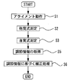
本実施形態において、例えば、制御手段は、自覚式測定手段によって被検眼の光学特性を自覚的に測定している間に、他覚式測定手段によって被検眼の光学特性を他覚的に測定する。なお、例えば、他覚式測定手段によって被検眼の光学特性を他覚的に測定する際には、自覚式測定手段による被検眼の光学特性の自覚的な測定を続けてもよい。また、例えば、他覚式測定手段によって被検眼の光学特性を他覚的に測定する際には、自覚式測定手段による被検眼の光学特性の自覚的な測定を一時的に停止させるようにしてもよい。この場合、他覚式測定手段によって他覚測定が完了した場合に、自覚式測定手段による被検眼の光学特性の自覚的な測定を再開するようにしてもよい。
<Acquisition of objective measurement results during subjective measurement>
In the present embodiment, for example, the control means objectively measures the optical characteristics of the eye to be inspected by the objective measuring means while the optical characteristics of the eye to be inspected are subjectively measured by the subjective measuring means. .. For example, when objectively measuring the optical characteristics of the eye to be inspected by the objective measuring means, the subjective measurement of the optical characteristics of the eye to be inspected by the subjective measuring means may be continued. Further, for example, when objectively measuring the optical characteristics of the eye to be inspected by the objective measuring means, the subjective measurement of the optical characteristics of the eye to be inspected by the subjective measuring means is temporarily stopped. May be good. In this case, when the objective measurement is completed by the objective measuring means, the subjective measurement of the optical characteristics of the eye to be inspected by the subjective measuring means may be restarted.
例えば、本実施形態において、自覚式測定手段によって被検眼の光学特性を自覚的に測定している間に、他覚式測定手段によって被検眼の光学特性を他覚的に測定する構成を備えることによって、他覚的な測定結果から自覚式の測定の間における被検眼の光学特性の変化を捉えることができる。これによって、検者は、自覚式の測定の間における被検眼の光学特性の変化を考慮した自覚的な測定を行うことができる。このため、検者は、被検眼の光学特性を自覚的に測定する際に、被検眼の光学特性を精度よく測定することができる。 For example, in the present embodiment, a configuration is provided in which the optical characteristics of the eye to be inspected are objectively measured by the objective measurement means while the optical characteristics of the eye to be inspected are subjectively measured by the subjective measurement means. Therefore, it is possible to capture the change in the optical characteristics of the eye to be inspected during the subjective measurement from the objective measurement result. This allows the examiner to make a subjective measurement in consideration of the change in the optical characteristics of the eye to be inspected during the subjective measurement. Therefore, when the examiner subjectively measures the optical characteristics of the eye to be inspected, the examiner can accurately measure the optical characteristics of the eye to be inspected.
例えば、自覚式測定手段によって被検眼の光学特性を自覚的に測定している間に、他覚式測定手段によって被検眼の光学特性を他覚的に測定する場合としては、制御手段は、少なくとも1つ以上の自覚検査をしている間に、他覚式測定手段によって被検眼の光学特性を他覚的に測定してもよい。 For example, when the optical characteristics of the eye to be inspected are objectively measured by the objective measuring means while the optical characteristics of the eye to be inspected are subjectively measured by the subjective measuring means, the control means is at least. The optical characteristics of the eye to be inspected may be objectively measured by objective measuring means while performing one or more subjective tests.
例えば、少なくとも1つ以上の自覚検査とは、1つの自覚検査を実施している場合、複数の自覚検査を実施している場合、を含む。なお、例えば、1つの自覚検査は、被検眼の少なくとも1つの光学特性を自覚的に測定する検査であってもよい。 For example, at least one subjective test includes a case where one subjective test is performed and a case where a plurality of subjective tests are performed. Note that, for example, one subjective test may be a test that subjectively measures at least one optical characteristic of the eye to be inspected.
例えば、1つの自覚検査を実施している場合、制御手段が、自覚式測定手段によって1つの自覚検査を実施している間に、他覚式測定手段によって被検眼の光学特性を他覚的に測定するようにしてもよい。 For example, when one subjective test is being performed, the objective measuring means objectively changes the optical characteristics of the eye to be inspected while the control means is performing one subjective test by the subjective measuring means. It may be measured.
例えば、複数の自覚検査を実施している場合、制御手段は、自覚式測定手段によって複数の自覚検査の内の1つの自覚検査を実施している間に、他覚式測定手段によって被検眼の光学特性を他覚的に測定するようにしてもよい。また、例えば、複数の自覚検査を実施している場合、制御手段は、自覚式測定手段によって第1の自覚検査と、第2の自覚検査と、の検査間に、他覚式測定手段によって被検眼の光学特性を他覚的に測定するようにしてもよい。この場合、例えば、第1自覚検査と第2自覚検査が同一の光学特性を測定するための自覚検査であってもよいし、第1自覚検査と第2自覚検査が異なる光学特性を測定するための自覚検査であってもよい。 For example, when a plurality of subjective tests are performed, the control means may be used by the objective measuring means to measure the eye to be inspected while the subjective measuring means is performing the subjective test of one of the plurality of subjective tests. The optical characteristics may be objectively measured. Further, for example, when a plurality of subjective tests are performed, the control means is subjected to the objective measuring means between the first subjective test and the second subjective test by the subjective measuring means. The optical characteristics of the optometry may be objectively measured. In this case, for example, the first subjective test and the second subjective test may be a subjective test for measuring the same optical characteristics, or the first subjective test and the second subjective test may measure different optical characteristics. It may be a subjective test of.
例えば、自覚式検眼装置は、他覚式測定手段による他覚的な測定を開始するための他覚測定開始トリガ信号を送信する送信手段と、他覚測定開始トリガ信号を受信する受信手段を備えてもよい。例えば、送信手段によって、他覚測定開始トリガ信号が送信され、受信手段によって、他覚測定開始トリガ信号が受信されると、制御手段は、少なくとも1つ以上の自覚検査をしている間に、他覚式測定手段によって被検眼の光学特性を他覚的に測定する。例えば、他覚式測定手段による他覚的な測定を開始は、手動によって実施されてもよいし、自動によって実施されてもよい。 For example, the subjective optometry device includes a transmitting means for transmitting an objective measurement start trigger signal for initiating an objective measurement by an objective measuring means, and a receiving means for receiving the objective measurement start trigger signal. You may. For example, when an objective measurement start trigger signal is transmitted by the transmitting means and an objective measurement start trigger signal is received by the receiving means, the control means is performing an at least one subjective test. The optical characteristics of the eye to be inspected are objectively measured by an objective measuring means. For example, the objective measurement by the objective measuring means may be started manually or automatically.
例えば、他覚的な測定の開始を手動で実施する構成の場合、他覚的な測定を開始するための他覚測定開始トリガ信号を自覚式検眼装置に送信する送信手段として開始スイッチを設ける。例えば、検者によって開始スイッチが選択されることによって、他覚測定開始トリガ信号が送信される。例えば、受信手段によって他覚測定開始トリガ信号が受信されると、制御手段が他覚式測定手段による測定を開始するようにしてもよい。例えば、少なくとも1つ以上の自覚検査をしている間に、他覚式測定手段によって被検眼の光学特性を他覚的に測定する構成としては、少なくとも1回の他覚的な測定が実施されるようにすればよい。すなわち、例えば、少なくとも1つ以上の自覚検査をしている間に、他覚式測定手段によって被検眼の光学特性を他覚的に測定する構成としては、最少の測定回数として、1回の他覚的な測定が実施されるようにしてもよいし、最大の測定回数として、常時(リアルタイムに)の他覚的な測定が実施されるようにしてもよい。 For example, in the case of a configuration in which the start of the objective measurement is manually performed, a start switch is provided as a transmission means for transmitting the objective measurement start trigger signal for starting the objective measurement to the subjective optometry device. For example, when the start switch is selected by the examiner, the objective measurement start trigger signal is transmitted. For example, when the objective measurement start trigger signal is received by the receiving means, the control means may start the measurement by the objective measurement means. For example, as a configuration for objectively measuring the optical characteristics of the eye to be inspected by an objective measuring means while performing at least one subjective test, at least one objective measurement is performed. You can do it. That is, for example, as a configuration for objectively measuring the optical characteristics of the eye to be inspected by the objective measuring means while performing at least one subjective test, the minimum number of measurements is one, etc. Optometric measurements may be performed, or the maximum number of measurements may be constant (real-time) objective measurements.
例えば、他覚的な測定を1回実施したい場合には、少なくとも1つ以上の自覚検査をしている間に、検者が開始スイッチを1回選択することで、他覚的な測定が実施されるようにしてもよい。 For example, if one wants to perform an objective measurement, the examiner can select the start switch once while performing at least one subjective test to perform the objective measurement. It may be done.
また、例えば、他覚的な測定を複数回実施したい場合には、少なくとも1つ以上の自覚検査をしている間に、検者が開始スイッチを複数回選択することで、複数回の他覚的な測定が実施されるようにしてもよい。また、例えば、他覚的な測定を複数回実施したい場合には、少なくとも1つ以上の自覚検査をしている間に、検者が開始スイッチを1回選択することで、複数回の他覚的な測定が実施されるようにしてもよい。 Further, for example, when it is desired to perform objective measurement multiple times, the examiner selects the start switch multiple times while performing at least one subjective test, so that the objective measurement is performed multiple times. Measurement may be performed. Further, for example, when it is desired to perform objective measurement multiple times, the examiner selects the start switch once while performing at least one subjective test, so that the objective measurement is performed multiple times. Measurement may be performed.
なお、例えば、1回の他覚測定開始トリガ信号が出力されることで複数回の他覚的な測定が実施される場合、少なくとも1つ以上の自覚検査をしている間に、検者が開始スイッチを1回選択することで、予め設定された回数の他覚的な測定が実施されるようにしてもよい。また、例えば、1回の他覚測定開始トリガ信号が出力されることで複数回の他覚的な測定が実施される場合、少なくとも1つ以上の自覚検査をしている間に、検者が開始スイッチを1回選択することで、予め設定されたタイミングで他覚的な測定が実施されるようにしてもよい。また、例えば、1回の他覚測定開始トリガ信号が出力されることで複数回の他覚的な測定が実施される場合、少なくとも1つ以上の自覚検査をしている間に、検者が開始スイッチを1回選択することで、常時測定を実施して、リアルタイムに他覚的な測定を実施されていくようにしてもよい。 In addition, for example, when a plurality of objective measurements are performed by outputting one objective measurement start trigger signal, the examiner may perform at least one subjective test. By selecting the start switch once, the objective measurement may be performed a preset number of times. Further, for example, when a plurality of objective measurements are performed by outputting one objective measurement start trigger signal, the examiner may perform at least one subjective test. By selecting the start switch once, the objective measurement may be performed at a preset timing. Further, for example, when a plurality of objective measurements are performed by outputting one objective measurement start trigger signal, the examiner may perform at least one subjective test. By selecting the start switch once, the measurement may be constantly performed and the objective measurement may be performed in real time.
例えば、他覚的な測定の開始を自動で実施する構成の場合、自覚検査が開始された後、制御手段が送信手段を制御して、予め設定されたタイミングで他覚測定開始トリガ信号を送信する。例えば、受信手段によって、他覚測定開始トリガ信号が受信されると、制御手段が他覚式測定手段による測定が開始するようにしてもよい。なお、本実施形態においては、送信手段の制御は、制御手段によって実施されているがこれに限定されない。例えば、制御手段とは異なる制御手段が別途設けられることによって実施されてもよい。 For example, in the case of a configuration in which the start of objective measurement is automatically performed, after the subjective test is started, the control means controls the transmission means and transmits the objective measurement start trigger signal at a preset timing. do. For example, when the objective measurement start trigger signal is received by the receiving means, the control means may start the measurement by the objective measurement means. In the present embodiment, the control of the transmission means is performed by the control means, but the control thereof is not limited to this. For example, it may be implemented by separately providing a control means different from the control means.
例えば、予め設定されたタイミングとしては、自覚的な測定の開始時(例えば、視標光束の投影する開始した状態、検査プログラムを開始した状態、自覚式検査装置の操作部の操作を開始した状態、矯正光学系の駆動を開始した状態等)、予め設定された時間の経過時(例えば、自覚的な測定の開始から所定時間経過時等)、検査視標の切り換え時、自覚検査と自覚検査との間(複数の自覚検査を行う場合)、被検者が自覚検査における回答をした時(検者が被検者回答に基づく操作を行った時)等の少なくともいずれかであってもよい。もちろん、上記記載以外のタイミングで、他覚測定開始トリガ信号が出力されるようにしてもよい。 For example, the preset timing includes a state in which the subjective measurement is started (for example, a state in which the projection of the target luminous flux is started, a state in which the inspection program is started, and a state in which the operation unit of the subjective inspection device is started. , When the driving of the corrective optical system is started, etc.), when a preset time has elapsed (for example, when a predetermined time has elapsed from the start of subjective measurement), when switching inspection targets, subjective examination and subjective examination (When performing multiple subjective tests), when the subject responds to the subjective test (when the examiner performs an operation based on the subject's answer), and so on. .. Of course, the objective measurement start trigger signal may be output at a timing other than the above description.
例えば、少なくとも1つ以上の自覚検査をしている間に、他覚式測定手段によって被検眼の光学特性を他覚的に測定する構成としては、少なくとも1回の他覚的な測定が実施されるようにすればよい。すなわち、例えば、少なくとも1つ以上の自覚検査をしている間に、他覚式測定手段によって被検眼の光学特性を他覚的に測定する構成としては、最少の測定回数として、1回の他覚的な測定が実施されるようにしてもよいし、最大の測定回数として、常時(リアルタイムに)の他覚的な測定が実施されるようにしてもよい。 For example, as a configuration for objectively measuring the optical characteristics of the eye to be inspected by an objective measuring means while performing at least one subjective test, at least one objective measurement is performed. You can do it. That is, for example, as a configuration for objectively measuring the optical characteristics of the eye to be inspected by the objective measuring means while performing at least one subjective test, the minimum number of measurements is one, etc. Optometric measurements may be performed, or the maximum number of measurements may be constant (real-time) objective measurements.
例えば、他覚的な測定を1回実施したい場合には、少なくとも1つ以上の自覚検査をしている間に、予め設定されたタイミングで他覚測定開始トリガが出力されるようにし、他覚式測定手段による測定が開始されるようにしてもよい。 For example, if you want to perform objective measurement once, you can output the objective measurement start trigger at a preset timing while performing at least one subjective test. The measurement by the formula measuring means may be started.
また、例えば、他覚的な測定を複数回実施したい場合には、少なくとも1つ以上の自覚検査をしている間に、予め設定されたタイミングで他覚測定開始トリガが出力されるようにし、複数回の他覚的な測定が実施されるようにしてもよい。この場合、例えば、少なくとも1つ以上の自覚検査をしている間に、複数回の他覚測定開始トリガ信号が出力されることで複数回の他覚的な測定が実施されるようにしてもよい。この場合、例えば、少なくとも1つ以上の自覚検査をしている間に、1回の他覚測定開始トリガ信号が出力されることで複数回の他覚的な測定が実施されるようにしてもよい。 Further, for example, when it is desired to perform objective measurement multiple times, the objective measurement start trigger is output at a preset timing while at least one subjective test is being performed. Multiple objective measurements may be performed. In this case, for example, even if a plurality of objective measurements are performed by outputting a plurality of objective measurement start trigger signals while performing at least one subjective test. good. In this case, for example, even if one objective measurement start trigger signal is output while performing at least one subjective test, a plurality of objective measurements are performed. good.
なお、例えば、1回の他覚測定開始トリガ信号が出力されることで複数回の他覚的な測定が実施される場合、少なくとも1つ以上の自覚検査をしている間に、1回の他覚測定開始トリガが出力されることで、予め設定された回数の他覚的な測定が実施されるようにしてもよい。また、例えば、1回の他覚測定開始トリガ信号が出力されることで複数回の他覚的な測定が実施される場合、少なくとも1つ以上の自覚検査をしている間に、1回の他覚測定開始トリガが出力されることで、予め設定されたタイミングで複数回の他覚的な測定が実施されるようにしてもよい。また、例えば、1回の他覚測定開始トリガ信号が出力されることで複数回の他覚的な測定が実施される場合、常時測定を実施して、リアルタイムに他覚的な測定を実施されていくようにしてもよい。 In addition, for example, when a plurality of objective measurements are performed by outputting one objective measurement start trigger signal, one objective measurement is performed while at least one subjective test is performed. By outputting the objective measurement start trigger, the objective measurement may be performed a preset number of times. Further, for example, when a plurality of objective measurements are performed by outputting one objective measurement start trigger signal, one objective measurement is performed while at least one subjective test is performed. By outputting the objective measurement start trigger, the objective measurement may be performed a plurality of times at a preset timing. Further, for example, when a plurality of objective measurements are performed by outputting one objective measurement start trigger signal, the constant measurement is performed and the objective measurement is performed in real time. You may try to go.
<調節情報取得>
例えば、本実施形態において、制御手段は、他覚式測定手段によって被検眼の光学特性を他覚的に測定して第1光学特性を取得するとともに、自覚式測定手段によって被検眼の光学特性を自覚的に測定している間に、他覚式測定手段によって被検眼の光学特性を他覚的に測定して第2光学特性を取得する。
<Acquisition of adjustment information>
For example, in the present embodiment, the control means objectively measures the optical characteristics of the eye to be inspected by the objective measuring means to acquire the first optical characteristics, and the subjective measuring means measures the optical characteristics of the eye to be inspected. While the measurement is performed subjectively, the optical characteristics of the eye to be inspected are objectively measured by the objective measuring means to acquire the second optical characteristics.
例えば、本実施形態において、自覚的検眼装置は、取得手段を備えてもよい。例えば、本実施例において、自覚的検眼装置は、出力手段を備えてもよい。例えば、取得手段は、第1光学特性及び第2光学特性に基づく調節情報を取得する。例えば、出力手段は、調節情報を出力する。例えば、本実施形態において、他覚的に測定して第1光学特性を取得するとともに、被検眼の光学特性を自覚的に測定している間に、他覚的に測定した第2光学特性を取得する。取得した第1光学特性及び第2光学特性に基づく調節情報を取得し、調節情報を出力する。このような構成によって、自覚式の測定の間における被検眼の光学特性の変化が被検眼の第1光学特性及び第2光学特性に基づく調節情報から容易に取得することができる。このため、検者は、調節情報を用いることで、被検眼の光学特性を自覚的に測定する際に、被検眼の光学特性を容易に精度よく測定できる。 For example, in the present embodiment, the subjective optometry device may include acquisition means. For example, in this embodiment, the subjective optometry device may include output means. For example, the acquisition means acquires adjustment information based on the first optical characteristic and the second optical characteristic. For example, the output means outputs adjustment information. For example, in the present embodiment, the first optical characteristic is objectively measured and the second optical characteristic is objectively measured while the optical characteristic of the eye to be inspected is subjectively measured. get. The adjustment information based on the acquired first optical characteristic and the second optical characteristic is acquired, and the adjustment information is output. With such a configuration, changes in the optical characteristics of the eye to be inspected during the subjective measurement can be easily obtained from the adjustment information based on the first optical characteristics and the second optical characteristics of the inspected eye. Therefore, the examiner can easily and accurately measure the optical characteristics of the eye to be inspected when subjectively measuring the optical characteristics of the eye to be inspected by using the adjustment information.
なお、例えば、調節情報を取得する際の第1光学特性及び第2光学特性としては、被検眼の調節状態の変化による影響がより生じやすい眼屈折力を用いることで、より光学特性の変化を捉えやすい。さらに、眼屈折力を用いる場合には、少なくとも球面度数を用いると、より光学特性の変化を捉えやすい。もちろん、調節情報を取得する際に、眼屈折力を用いる場合には、球面度数、乱視度数、及び乱視軸角度の少なくともいずれかが用いられる構成であってもよい。 For example, as the first optical characteristic and the second optical characteristic when acquiring the accommodation information, the change in the optical characteristic can be further changed by using the optical refractive power that is more likely to be affected by the change in the accommodation state of the eye to be inspected. Easy to catch. Further, when the optical power is used, it is easier to capture the change in the optical characteristics by using at least the spherical power. Of course, when the ocular refractive power is used when acquiring the accommodation information, at least one of the spherical power, the astigmatic power, and the astigmatic axis angle may be used.
例えば、第1光学特性を取得するタイミングとしては、自覚式測定手段によって被検眼の光学特性を自覚的に測定する以前に取得するようにしてもよい。この場合、例えば、制御手段は、自覚式測定手段によって被検眼の光学特性を自覚的に測定する以前に、他覚式測定手段によって被検眼の光学特性を他覚的に測定し、第1光学特性を取得するようにしてもよい。例えば、本実施形態において、自覚式測定手段によって被検眼の光学特性を自覚的に測定する以前に、他覚式測定手段によって被検眼の光学特性を他覚的に測定している。これによって、自覚式測定手段による自覚式の測定の前に、他覚式の測定が行われるため、自覚式測定手段を使用していることによって生じる光学特性の変化を抑制した状態で、他覚式の測定による光学特性を取得できる。このため、光学特性の変化が抑制された他覚式の測定による光学特性を取得することができ、より良好な調節情報を取得することができる。 For example, the timing for acquiring the first optical characteristic may be acquired before the optical characteristic of the eye to be inspected is subjectively measured by the subjective measuring means. In this case, for example, the control means objectively measures the optical characteristics of the eye to be inspected by the objective measurement means before the optical characteristics of the eye to be inspected are subjectively measured by the subjective measurement means, and the first optical The characteristics may be acquired. For example, in the present embodiment, the optical characteristics of the eye to be inspected are objectively measured by the objective measuring means before the optical characteristics of the eye to be inspected are subjectively measured by the subjective measuring means. As a result, the objective measurement is performed before the subjective measurement by the subjective measurement means, so that the change in the optical characteristics caused by the use of the subjective measurement means is suppressed, and the objective measurement is performed. The optical characteristics can be obtained by measuring the equation. Therefore, it is possible to acquire the optical characteristics by objective measurement in which the change in the optical characteristics is suppressed, and it is possible to acquire better adjustment information.
例えば、第1光学特性を取得するタイミングとしては、自覚式測定手段によって被検眼の光学特性を自覚的に測定した後に取得するようにしてもよい。この場合、例えば、制御手段は、自覚式測定手段によって被検眼の光学特性を自覚的な測定が完了した後、他覚式測定手段によって被検眼の光学特性を他覚的に測定し、第1光学特性を取得するようにしてもよい。例えば、本実施形態において、自覚式測定手段によって被検眼の光学特性を自覚的に測定した後に、他覚式測定手段によって被検眼の光学特性を他覚的に測定している。これによって、自覚式測定手段による自覚式の測定した後に、他覚式の測定が行われるため、自覚式測定手段を使用していることによって生じる光学特性の変化を抑制した状態で、他覚式の測定による光学特性を取得できる。このため、光学特性の変化が抑制された他覚式の測定による光学特性を取得することができ、より良好な調節情報を取得することができる。 For example, as the timing for acquiring the first optical characteristic, the optical characteristic of the eye to be inspected may be acquired after being subjectively measured by the subjective measuring means. In this case, for example, the control means objectively measures the optical characteristics of the eye to be inspected by the objective measurement means after the subjective measurement of the optical characteristics of the eye to be inspected is completed by the subjective measurement means. The optical characteristics may be acquired. For example, in the present embodiment, the optical characteristics of the eye to be inspected are subjectively measured by the subjective measuring means, and then the optical characteristics of the eye to be inspected are objectively measured by the objective measuring means. As a result, the objective type measurement is performed after the subjective type measurement by the subjective type measuring means. Therefore, the objective type measurement is performed while suppressing the change in the optical characteristics caused by using the subjective type measuring means. The optical characteristics can be obtained by the measurement of. Therefore, it is possible to acquire the optical characteristics by objective measurement in which the change in the optical characteristics is suppressed, and it is possible to acquire better adjustment information.
なお、第1光学特性を取得する場合に、被検眼Eに対して雲霧がかけるようにしてもよい。例えば、第1光学特性を取得する場合の他覚眼屈折力の測定においては、はじめに眼屈折力の予備測定が行われ、予備測定の結果に基づいて、被検眼Eに対して雲霧がかけられてもよい。例えば、予備測定としては、他覚式測定手段によって測定される他覚眼屈折力の測定であってもよいし、自覚式測定手段によって測定される自覚眼屈折力の測定であってもよい。 When acquiring the first optical characteristic, cloud fog may be applied to the eye E to be inspected. For example, in the measurement of the objective optical power when acquiring the first optical characteristic, a preliminary measurement of the optical power is first performed, and a cloud fog is applied to the eye E to be inspected based on the result of the preliminary measurement. You may. For example, the preliminary measurement may be the measurement of the objective eye refractive power measured by the objective measuring means, or the measurement of the subjective eye refractive power measured by the subjective measuring means.
例えば、雲霧をかける場合には、ディスプレイ31が光軸L2方向に移動されることにより、被検眼Eに対して雲霧がかけられてもよい。この場合、例えば、ディスプレイ31が被検眼Eに対して、一度ピントが合う位置に移動されてもよい。また、例えば、雲霧をかける場合には、光学部材(例えば、レンズ等)を光路に挿脱するようにしてもよい。また、例えば、雲霧をかける場合には、光路に配置する光学部材(例えば、レンズ等)を切り換えるようにしてもよい。例えば、雲霧がかけられた後、雲霧がかけられた被検眼に対して、第1光学特性を取得するための眼屈折力の本測定が行われてもよい。このように、雲霧をかけることによって、被検眼の調節機能を抑制することができ、調整機能の抑制された状態での第1光学特性を取得することができる。
For example, in the case of applying cloud fog, the
また、例えば、第1光学特性を取得するタイミングとしては、自覚式測定手段によって被検眼の光学特性を自覚的に測定している間に取得するようにしてもよい。この場合、例えば、自覚式測定手段によって被検眼の光学特性を自覚的に測定している間に第1光学特性を取得するとともに、第1光学特性を取得した後に第2光学特性を取得するようにしてもよい。 Further, for example, the timing for acquiring the first optical characteristic may be acquired while the optical characteristic of the eye to be inspected is subjectively measured by the subjective measuring means. In this case, for example, the first optical characteristic is acquired while the optical characteristic of the eye to be inspected is subjectively measured by the subjective measuring means, and the second optical characteristic is acquired after the first optical characteristic is acquired. You may do it.
例えば、調節情報は、第1光学特性及び第2光学特性が比較可能な情報であればよい。例えば、調節情報としては、第1光学特性と、第2光学特性と、を差分処理することによって取得された情報であってもよい。例えば、差分処理することで取得される調節情報は、第1光学特性と第2光学特性とのパラメータの差分結果、及び撮像画像の差分画像等の少なくともいずれかであってもよい。なお、例えば、上記のパラメータとしては、球面度数値、乱視度数値、乱視軸角度値等の少なくともいずれかの数値であってもよい。 For example, the adjustment information may be any information as long as the first optical characteristic and the second optical characteristic can be compared. For example, the adjustment information may be information acquired by performing a difference process between the first optical characteristic and the second optical characteristic. For example, the adjustment information acquired by the difference processing may be at least one of the difference result of the parameters of the first optical characteristic and the second optical characteristic, the difference image of the captured image, and the like. For example, the above parameter may be at least one of a spherical surface degree value, an astigmatism degree value, an astigmatism axis angle value, and the like.
例えば、差分画像としては、撮像画像間の画素毎の輝度値を差分処理した画像であってもよい。この場合、例えば、第1光学特性と第2光学特性で変化がない場合には、差分画像における各画素の輝度値が0となる(同一の撮像画像となるため、その差分が0となる)。また、この場合、例えば、第1光学特性と第2光学特性で変化がある場合には、差分画像には、各撮像画像の輝度値が0とならないため画像上に像が現れる。 For example, the difference image may be an image obtained by performing difference processing on the luminance values for each pixel between the captured images. In this case, for example, when there is no change between the first optical characteristic and the second optical characteristic, the luminance value of each pixel in the difference image becomes 0 (since the same captured image is obtained, the difference becomes 0). .. Further, in this case, for example, when there is a change between the first optical characteristic and the second optical characteristic, an image appears on the difference image because the luminance value of each captured image does not become zero.
なお、例えば、差分処理を行う場合には、差分処理を行うための基準の光学特性(基準データ)としては、任意の光学特性を設定できるようにしてもよい。例えば、差分結果としては、基準データに対して、各光学特性が差分処理されることによって、取得されるようにしてもよい。 For example, in the case of performing the difference processing, any optical characteristic may be set as the reference optical characteristic (reference data) for performing the difference processing. For example, the difference result may be acquired by performing difference processing on each optical characteristic with respect to the reference data.
例えば、第1光学特性及び第2光学特性のみを取得した場合には、第1光学特性及び第2光学特性の少なくとも一方を基準データとしてもよい。例えば、第1光学特性及び第2光学特性の他にさらに光学特性を取得した場合には、取得された光学特性の中から任意の光学特性を基準データとして設定すればよい。なお、例えば、光学特性を基準データとして設定する場合に、複数の光学特性の中から検者によって基準データを選択してもよい。また、例えば、光学特性を基準データとして設定する場合に、取得手段によって、自動的に基準データが設定されるようにしてもよい。この場合、例えば、取得手段は、複数の光学特性の中から光学特性が最小(最も遠点側(眼の調節が入っていない側))のものを基準データとして設定してもよい。また、例えば、取得手段は、複数の光学特性の中から光学特性が新たに取得された基準データの直前に取得された光学特性を基準データとして設定してもよい。また、例えば、取得手段は、複数の自覚検査が実施されている場合に、複数の自覚検査の中で他覚式測定によって取得された光学特性から任意の光学特性を基準データとして設定してもよい。 For example, when only the first optical characteristic and the second optical characteristic are acquired, at least one of the first optical characteristic and the second optical characteristic may be used as reference data. For example, when further optical characteristics are acquired in addition to the first optical characteristics and the second optical characteristics, any optical characteristics may be set as reference data from the acquired optical characteristics. For example, when the optical characteristics are set as the reference data, the reference data may be selected by the examiner from a plurality of optical characteristics. Further, for example, when the optical characteristics are set as the reference data, the reference data may be automatically set by the acquisition means. In this case, for example, the acquisition means may set the one having the smallest optical characteristic (the farthest side (the side without eye adjustment)) as the reference data from the plurality of optical characteristics. Further, for example, the acquisition means may set the optical characteristics acquired immediately before the reference data for which the optical characteristics are newly acquired from the plurality of optical characteristics as the reference data. Further, for example, when a plurality of subjective tests are performed, the acquisition means may set arbitrary optical characteristics as reference data from the optical characteristics acquired by objective measurement in the plurality of subjective tests. good.
なお、差分結果として、数値、グラフ等で表示するようにしてもよい。例えば、リアルタイムに他覚式測定又は複数回の他覚式測定を行う場合に、それらの差分結果が連続的に表示されるようにしてもよい。このような構成とすれば、光学特性の変動状態を確認することができる。 It should be noted that the difference result may be displayed as a numerical value, a graph, or the like. For example, when objective measurement or a plurality of objective measurements are performed in real time, the difference results thereof may be continuously displayed. With such a configuration, it is possible to confirm the fluctuation state of the optical characteristics.
なお、例えば、差分結果、及び差分画像の少なくともいずれかに基づいて、光学特性の変化の良否を判定するようにしてもよい。この場合、例えば、判定手段が設けられ、判定手段が差分結果、及び撮像画像の形状変化結果等の少なくともいずれかの結果が予め設定された基準を満たすか否かを判定し、判定結果を出力するようにしてもよい。例えば、判定結果として、過矯正である否かが出力されるようにしてもよい。 In addition, for example, the quality of the change in the optical characteristics may be determined based on at least one of the difference result and the difference image. In this case, for example, a determination means is provided, and the determination means determines whether or not at least one of the results such as the difference result and the shape change result of the captured image satisfies a preset standard, and outputs the determination result. You may try to do it. For example, as a determination result, whether or not it is overcorrected may be output.
例えば、本実施形態において、調節情報が比較処理によって取得されることによって、自覚式の測定の間における被検眼の光学特性の変化が、比較処理された調節情報から、より容易に取得できる。このため、検者は、調節情報を用いることで、被検眼の光学特性を自覚的に測定する際に、被検眼の光学特性をより容易に精度よく測定できる。 For example, in the present embodiment, by acquiring the adjustment information by the comparative processing, the change in the optical characteristics of the eye to be inspected during the subjective measurement can be more easily acquired from the comparative processing. Therefore, the examiner can more easily and accurately measure the optical characteristics of the eye to be inspected when subjectively measuring the optical characteristics of the eye to be inspected by using the adjustment information.
例えば、調節情報としては、第1光学特性及び第2光学特性であってもよい。この場合、例えば、調節情報としては、第1光学特性及び第2光学特性が並べられた情報(例えば、第1光学特性が配置された第1領域、第1領域とは異なる第2領域に第2光学特性が配置された情報)であってもよい。また、この場合、調節情報としては、第1光学特性と第2光学特性を切り換え表示可能な情報であってもよい。また、この場合、例えば、調節情報としては、第1光学特性と第2光学特性とが重畳された情報であってもよい。なお、重畳された情報とは、第1光学特性と、第2光学特性と、の内少なくとも一部が重畳されている情報であってもよい。なお、例えば、調節情報としては、上記情報が併用して実施される構成としてもよい。 For example, the adjustment information may be the first optical characteristic and the second optical characteristic. In this case, for example, as the adjustment information, the information in which the first optical characteristic and the second optical characteristic are arranged (for example, the first region in which the first optical characteristic is arranged, and the second region different from the first region are the first. (2) Information in which optical characteristics are arranged) may be used. Further, in this case, the adjustment information may be information that can be displayed by switching between the first optical characteristic and the second optical characteristic. Further, in this case, for example, the adjustment information may be information in which the first optical characteristic and the second optical characteristic are superimposed. The superimposed information may be information in which at least a part of the first optical characteristic and the second optical characteristic is superimposed. In addition, for example, the adjustment information may be configured to be implemented in combination with the above information.
例えば、本実施形態において、自覚的検眼装置は、出力手段を備えてもよい。例えば、出力手段は、調節情報を出力する。例えば、出力手段は、調節情報をディスプレイに表示する構成であってもよい。また、例えば、出力手段は、調節情報を印刷する構成であってもよい。例えば、出力手段は、調節情報を他の装置(他の制御手段)に向けて送信する構成であってもよい。この場合、例えば、他の装置は、調節情報を受信し、受信した調節情報に基づいて各種制御が行われるようにしてもよい。 For example, in this embodiment, the subjective optometry device may include output means. For example, the output means outputs adjustment information. For example, the output means may be configured to display adjustment information on a display. Further, for example, the output means may be configured to print adjustment information. For example, the output means may be configured to transmit adjustment information to another device (another control means). In this case, for example, another device may receive the adjustment information and perform various controls based on the received adjustment information.
なお、本実施形態において、制御手段と、取得手段(取得制御手段)と、出力手段(出力制御手段)と、が兼用された構成であってもよい。また、例えば、制御手段と、取得手段と、出力手段と、が別途それぞれ設けられている構成であってもよい。もちろん、上記各制御手段は、複数の制御手段によって構成されてもよい。 In this embodiment, the control means, the acquisition means (acquisition control means), and the output means (output control means) may be used in combination. Further, for example, the control means, the acquisition means, and the output means may be separately provided. Of course, each of the above control means may be composed of a plurality of control means.
なお、本実施形態においては、自覚式測定手段によって被検眼の光学特性を自覚的に測定している間に、他覚式測定手段によって被検眼の光学特性を他覚的に測定する自覚式検眼装置を例に挙げて説明しているがこれに限定されない。自覚式検眼装置が調節情報を取得できる構成であってもよい。この場合、例えば、制御手段は、他覚式測定手段によって被検眼の光学特性を他覚的に測定して第1光学特性を取得するとともに、第1光学特性を取得したタイミングとは異なるタイミングにて、他覚式測定手段によって被検眼の光学特性を他覚的に測定して第2光学特性を取得するようにしてもよい。例えば、取得手段は、第1光学特性及び第2光学特性に基づく調節情報を取得するようにしてもよい。例えば、出力手段は、調節情報を出力するようにしてもよい。例えば、本実施形態において、被検眼の光学特性を他覚的に測定して第1光学特性を取得するとともに、第1光学特性を取得したタイミングとは異なるタイミングにて、他覚式測定手段によって被検眼の光学特性を他覚的に測定して第2光学特性を取得する。取得した第1光学特性及び第2光学特性に基づく調節情報を取得し、調節情報を出力する。このような構成によって、検者は、自覚式検眼装置を用いる場合に、被検眼の光学特性の変化状態を取得できる。これによって、自覚式検眼装置を用いて被検眼の測定を行う際に、被検眼を精度よく測定できる。 In the present embodiment, while the optical characteristics of the optometry to be inspected are subjectively measured by the subjective measuring means, the optical characteristics of the optometry to be inspected are objectively measured by the objective measuring means. The device is described as an example, but the description is not limited to this. The optometry device may be configured to be able to acquire adjustment information. In this case, for example, the control means objectively measures the optical characteristics of the eye to be inspected by the objective measuring means to acquire the first optical characteristics, and at a timing different from the timing at which the first optical characteristics are acquired. Then, the optical characteristics of the eye to be inspected may be objectively measured by the objective measuring means to acquire the second optical characteristics. For example, the acquisition means may acquire adjustment information based on the first optical characteristic and the second optical characteristic. For example, the output means may output adjustment information. For example, in the present embodiment, the optical characteristics of the eye to be inspected are objectively measured to acquire the first optical characteristics, and the objective measurement means is used at a timing different from the timing at which the first optical characteristics are acquired. The optical characteristics of the eye to be inspected are objectively measured to obtain the second optical characteristics. The adjustment information based on the acquired first optical characteristic and the second optical characteristic is acquired, and the adjustment information is output. With such a configuration, the examiner can acquire the changed state of the optical characteristics of the eye to be inspected when the subjective optometry device is used. This makes it possible to measure the optometry with high accuracy when measuring the optometry using the subjective optometry device.
<調節情報に基づく補正処理>
例えば、本実施形態において、自覚式検眼装置は設定手段(例えば、制御部70)を備えてもよい。例えば、本実施形態において、自覚式検眼装置は第1補正手段(例えば、制御部70、矯正光学系60)を備えてもよい。例えば、設定手段は、自覚式測定手段によって被検眼の光学特性を自覚的に測定している間に生じる被検眼の調節状態変化を補正するための補正量を調節情報に基づいて設定してもよい。なお、補正量としては、発生した被検眼の調節状態変化をキャンセルできる補正量に設定されることが好ましいが、自覚検査に支障が現れない程度であれば、これに限定されない。例えば、第1補正手段は、設定手段によって設定された補正量に基づいて、自覚式測定手段にて生じる被検眼の調節状態変化をキャンセルする補正を行ってもよい。例えば、本実施形態において、被検眼の調節状態変化を補正するための補正量を調節情報に基づいて設定し、補正量に基づいて、自覚式測定手段にて生じる被検眼の調節状態変化をキャンセルする補正を行っている。これによって、自覚式測定手段によって被検眼の光学特性を自覚的に測定している間に、被検眼の光学特性の変化が生じた場合であっても、光学特性の変化をキャンセルした状態で測定を行うことができる。これによって、被検眼の光学特性を自覚的に測定する際に、被検眼の光学特性を容易に精度よく測定できる。
<Correction processing based on adjustment information>
For example, in the present embodiment, the subjective optometry device may include a setting means (for example, a control unit 70). For example, in the present embodiment, the subjective optometry apparatus may include a first correction means (for example, a
例えば、補正量は、調節情報のパラメータ毎に予め設定されたテーブルが作成されてもよく、作成されたテーブルは、メモリ(例えば、メモリ72)に記憶されてもよい。この場合、例えば、設定手段は、調節状態に対応する補正量をメモリより呼び出し、設定するようにしてもよい。また、例えば、補正量は、調節情報のパラメータ毎の補正量を導出するための演算式がメモリに記憶され、演算式を用いて補正量を求めてもよい。 For example, as for the correction amount, a table preset for each parameter of the adjustment information may be created, and the created table may be stored in a memory (for example, a memory 72). In this case, for example, the setting means may call the correction amount corresponding to the adjustment state from the memory and set it. Further, for example, as the correction amount, an arithmetic expression for deriving the correction amount for each parameter of the adjustment information is stored in the memory, and the correction amount may be obtained using the arithmetic expression.
例えば、第1補正手段としては、矯正光学系が第1補正手段を兼用する構成であってもよい。例えば、本実施形態において、矯正光学系が第1補正手段を兼用することで、複雑な制御や、別途、調節状態変化をキャンセルするための補正手段を必要としないため、簡易的な構成で光学収差を補正することができる。例えば、第1補正手段としては、別途、専用の補正手段を設けるようにしてもよい。この場合、例えば、第1補正手段としては、例えば、第1補正手段として、球面レンズ、円柱レンズ、クロスシリンダレンズ、ロータリープリズム、波面変調素子等の少なくともいずれかを用いる構成であってもよい。もちろん、例えば、第1補正手段としては、上記記載の部材とは異なる部材を用いるようにしてもよい。 For example, as the first correction means, the correction optical system may also have a configuration in which the first correction means is also used. For example, in the present embodiment, since the correction optical system also serves as the first correction means, complicated control and a separate correction means for canceling the adjustment state change are not required, so that the optical system has a simple configuration. Aberrations can be corrected. For example, as the first correction means, a dedicated correction means may be separately provided. In this case, for example, as the first correction means, for example, at least one of a spherical lens, a cylindrical lens, a cross cylinder lens, a rotary prism, a wavefront modulation element, and the like may be used as the first correction means. Of course, for example, as the first correction means, a member different from the above-mentioned member may be used.
なお、本実施形態において、制御手段と、設定手段(設定制御手段)と、第1補正手段の制御手段と、が兼用された構成であってもよい。また、例えば、制御手段と、設定手段と、第1補正手段の制御手段と、が別途それぞれ設けられている構成であってもよい。もちろん、上記各制御手段は、複数の制御手段によって構成されてもよい。 In this embodiment, the control means, the setting means (setting control means), and the control means of the first correction means may be combined. Further, for example, the control means, the setting means, and the control means of the first correction means may be separately provided. Of course, each of the above control means may be composed of a plurality of control means.
<矯正光学系の矯正情報に基づく他覚測定結果の補正>
なお、本実施形態において、例えば、自覚式検眼装置としては、矯正光学系が測定光学系の光路中に配置されているように構成されていてもよい。もちろん、自覚式検眼装置としては、矯正光学系が測定光学系の光路中に配置されていない構成であってもよい。
<Correction of objective measurement results based on correction information of the correction optical system>
In the present embodiment, for example, the subjective optometry device may be configured such that the correction optical system is arranged in the optical path of the measurement optical system. Of course, the subjective optometry device may have a configuration in which the correction optical system is not arranged in the optical path of the measurement optical system.
例えば、矯正光学系が測定光学系の光路中に配置されている場合、自覚式検眼装置は、第2補正手段(例えば、制御部70)を備えてもよい。例えば、第2補正手段は、矯正光学系による矯正情報に基づいて、他覚式測定手段によって被検眼を他覚的に測定して得られた測定結果を補正するようにしてもよい。例えば、第2補正手段は、矯正光学系による矯正情報に基づいて、矯正光学系による矯正状態をキャンセルするように、他覚式測定手段によって被検眼を他覚的に測定して得られた測定結果を補正するようにしてもよい。例えば、本実施形態において、他覚測定手段の光路中に矯正光学系が存在する場合に、他覚を測定する測定光束が矯正光学系を経由することによって生じる光学特性のずれを補正することができる。これによって、矯正光学系によって矯正が行われている場合に他覚的な測定を行った場合であっても、光学特性が精度よく取得できる。例えば、特に、他覚的な測定によって取得された少なくとも2つの光学特性に基づく調節情報を取得する際には、光学特性間でずれが生じることで比較することが困難となることがあるため、本技術がより効果的である。 For example, when the correction optical system is arranged in the optical path of the measurement optical system, the subjective optometry apparatus may include a second correction means (for example, a control unit 70). For example, the second correction means may correct the measurement result obtained by objectively measuring the eye to be inspected by the objective measurement means based on the correction information by the correction optical system. For example, the second correction means objectively measures the eye to be inspected by the objective measuring means so as to cancel the correction state by the correction optical system based on the correction information by the correction optical system. The result may be corrected. For example, in the present embodiment, when the correction optical system is present in the optical path of the objective measurement means, it is possible to correct the deviation of the optical characteristics caused by the measured luminous flux for measuring the objective passing through the correction optical system. can. As a result, the optical characteristics can be accurately obtained even when the objective measurement is performed when the correction is performed by the correction optical system. For example, in particular, when acquiring adjustment information based on at least two optical characteristics acquired by objective measurement, it may be difficult to compare due to the deviation between the optical characteristics. This technique is more effective.
例えば、第2補正手段は、測定結果として、光学特性を補正するようにしてもよい。なお、光学特性として、第1光学特性と第2光学特性が取得されている場合には、第1光学特性及び第2光学特性の少なくとも一方を補正するようにすればよい。また、例えば、第2補正手段は、測定結果として、調節情報を補正するようにしてもよい。 For example, the second correction means may correct the optical characteristics as a measurement result. When the first optical characteristic and the second optical characteristic are acquired as the optical characteristics, at least one of the first optical characteristic and the second optical characteristic may be corrected. Further, for example, the second correction means may correct the adjustment information as a measurement result.
なお、本実施形態において、制御手段と、第2補正手段(第2補正制御手段)と、が兼用された構成であってもよい。また、例えば、制御手段と、第2補正手段と、が別途それぞれ設けられている構成であってもよい。もちろん、上記各制御手段は、複数の制御手段によって構成されてもよい。 In this embodiment, the control means and the second correction means (second correction control means) may be used in combination. Further, for example, the control means and the second correction means may be separately provided. Of course, each of the above control means may be composed of a plurality of control means.
なお、本実施形態において、自覚式測定手段によって被検眼の光学特性を自覚的に測定している間に、他覚式測定手段によって被検眼の光学特性を他覚的に測定する構成は、被検眼が眼鏡を装用している状態時における光学特性を自覚的に測定する自覚検査(前眼鏡検査)に用いるようにしてもよい。この場合、例えば、被検眼が眼鏡を装用している状態において、他覚式測定手段によって他覚的に測定して第1光学特性を取得するとともに、被検眼の光学特性を自覚的に測定している間に、他覚式測定手段によって他覚的に測定した第2光学特性を取得するようにしてもよい。また、例えば、取得した第1光学特性及び第2光学特性に基づく調節情報を取得し、調節情報を出力するようにしてもよい。 In the present embodiment, the configuration in which the optical characteristics of the eye to be inspected are objectively measured by the objective measuring means while the optical characteristics of the eye to be inspected are subjectively measured by the subjective measuring means is the subject. It may be used for a subjective test (anterior spectacle test) in which the optical characteristics of the optometry while wearing the spectacles are subjectively measured. In this case, for example, in a state where the eye to be inspected is wearing glasses, the first optical characteristic is acquired objectively by objective measurement by an objective measuring means, and the optical characteristic of the eye to be inspected is subjectively measured. In the meantime, the second optical characteristic measured objectively by the objective measuring means may be acquired. Further, for example, the adjustment information based on the acquired first optical characteristic and the second optical characteristic may be acquired and the adjustment information may be output.
例えば、調節情報として、差分結果、及び差分画像の少なくともいずれかを得た場合に、
例えば、差分結果、及び差分画像の少なくともいずれかに基づいて、光学特性の変化の良否を判定するようにしてもよい。この場合、例えば、判定結果として、過矯正である否かが出力されるようにしてもよい。例えば、過矯正である否かが出力されることによって、現在装用している眼鏡が過矯正となっていないか否かを確認することができる。
For example, when at least one of a difference result and a difference image is obtained as adjustment information,
For example, the quality of the change in the optical characteristics may be determined based on at least one of the difference result and the difference image. In this case, for example, whether or not it is overcorrected may be output as a determination result. For example, by outputting whether or not it is overcorrected, it is possible to confirm whether or not the glasses currently worn are not overcorrected.
例えば、一例として、被検眼が眼鏡を装用している状態時において、無限遠の遠方視用視標を呈示して光学特性を取得するとともに、無限遠の遠方視用視標よりもプラス度数の視標を呈示して光学特性を取得するようにしてもよい。この場合、算出された各光学特性に基づいて、調整状態を取得するようにしてもよい。これによって、現在装用している眼鏡が過矯正となっていないか否かを確認することができる。 For example, as an example, when the eye to be inspected is wearing spectacles, the optotype for infinity is presented to acquire optical characteristics, and the power is higher than that of the optotype for infinity. The optotype may be presented to acquire the optical characteristics. In this case, the adjustment state may be acquired based on each calculated optical characteristic. This makes it possible to confirm whether or not the glasses currently worn are overcorrected.
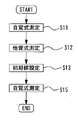
<自覚検査の初期値設定>
本実施形態において、例えば、自覚式検眼装置は、初期値設定手段(例えば、制御部70)を備えてもよい。この場合、例えば、制御手段は、自覚式測定手段によって被検眼の光学特性の自覚的な測定を開始した後、他覚式測定手段によって被検眼の光学特性を他覚的に測定して被検眼の光学特性を取得するようにしてもよい。例えば、初期値設定手段は、制御手段によって他覚的に測定された被検眼の光学特性を、自覚測定手段によって被検眼の光学特性を自覚的に測定する際の矯正光学系の初期値として設定するようにしてもよい。なお、例えば、初期値として設定される光学特性としては、球面度数、円柱度数、円柱軸、偏光特性、及び収差量、等の少なくともいずれかが挙げられる。もちろん、上記以外の光学特性が初期値として設定される構成としてもよい。例えば、本実施形態において、自覚式測定手段によって被検眼の光学特性の自覚的な測定を開始した後、他覚式測定手段によって被検眼の光学特性を他覚的に測定して被検眼の光学特性を取得する。他覚的に測定された被検眼の光学特性が、自覚測定手段によって被検眼の光学特性を自覚的に測定する際の矯正光学系の初期値として設定される。このような構成によって、他覚的な測定が完了するまで、自覚式検査装置による自覚的な測定の実施を待機する必要がなく、被検眼の光学特性を迅速に測定することができる。
<Initial value setting for subjective test>
In the present embodiment, for example, the subjective optometry device may include initial value setting means (for example, a control unit 70). In this case, for example, the control means objectively measures the optical characteristics of the eye to be inspected by the objective measurement means after starting the subjective measurement of the optical characteristics of the eye to be inspected by the subjective measurement means. The optical characteristics of the above may be acquired. For example, the initial value setting means sets the optical characteristics of the eye to be inspected objectively measured by the control means as the initial values of the correction optical system when the optical characteristics of the eye to be inspected are subjectively measured by the subjective measurement means. You may try to do it. For example, as the optical characteristic set as the initial value, at least one of spherical power, cylindrical power, cylindrical axis, polarization characteristic, aberration amount, and the like can be mentioned. Of course, an optical characteristic other than the above may be set as an initial value. For example, in the present embodiment, after the subjective measurement of the optical characteristics of the eye to be inspected is started by the subjective measurement means, the optical characteristics of the eye to be inspected are objectively measured by the objective measurement means to obtain the optics of the eye to be inspected. Get the characteristics. The objectively measured optical characteristics of the eye to be inspected are set as initial values of the correction optical system when the optical characteristics of the eye to be inspected are subjectively measured by the subjective measurement means. With such a configuration, it is not necessary to wait for the subjective measurement by the subjective inspection device until the objective measurement is completed, and the optical characteristics of the eye to be inspected can be measured quickly.
例えば、自覚的な測定の開始とは、自覚的な測定の制御が開始されている状態であればよい。より詳細には、例えば、自覚的な測定の開始とは、視標光束の投影を開始した状態、検査プログラムを開始した状態、自覚式検査装置の操作部の操作を開始した状態、矯正光学系の駆動を開始した状態等の少なくともいずれかであってもよい。 For example, the start of the subjective measurement may be a state in which the control of the subjective measurement is started. More specifically, for example, the start of subjective measurement means the state of starting the projection of the target luminous flux, the state of starting the inspection program, the state of starting the operation of the operation unit of the subjective inspection device, and the correction optical system. It may be at least one of the states in which the driving of the above is started.
例えば、初期値設定手段は、初期値として設定する自覚検査として、他覚的な測定を開始した際に実施されていた自覚検査において、他覚的に測定された被検眼の光学特性を初期値として設定する構成としてもよい。この場合、例えば、初期値設定手段は、他覚式測定手段によって他覚的に測定された被検眼の光学特性を、他覚式測定手段による他覚的な測定を開始する前に自覚式測定手段によって実施されていた被検眼の光学特性の自覚的な測定における矯正光学系の初期値として設定する。例えば、本実施形態において、他覚式測定手段によって他覚的に測定された被検眼の光学特性を、他覚式測定手段による他覚的な測定を開始する前に、自覚式測定手段によって実施されていた被検眼の光学特性の自覚的な測定における矯正光学系の初期値として設定する。このような構成によって、自覚式検査装置による自覚的な測定を迅速に行うことができる。 For example, the initial value setting means sets the optical characteristics of the eye to be objectively measured objectively as the initial value in the subjective test performed when the objective measurement is started as the subjective test to be set as the initial value. It may be configured as set as. In this case, for example, the initial value setting means subjectively measures the optical characteristics of the eye to be inspected objectively measured by the objective measuring means before starting the objective measurement by the objective measuring means. It is set as the initial value of the correction optical system in the subjective measurement of the optical characteristics of the eye to be inspected carried out by the means. For example, in the present embodiment, the optical characteristics of the eye to be inspected objectively measured by the objective measuring means are carried out by the subjective measuring means before the objective measurement by the objective measuring means is started. It is set as the initial value of the correction optical system in the subjective measurement of the optical characteristics of the eye to be inspected. With such a configuration, it is possible to quickly perform subjective measurement by a subjective inspection device.
また、例えば、初期値設定手段は、初期値として設定する自覚検査として、他覚的な測定を開始した際に実施されていた自覚検査(第1自覚検査)とは異なる自覚検査(第2自覚検査)において、他覚的に測定された被検眼の光学特性を初期値として設定する構成としてもよい。この場合、例えば、制御手段は、自覚式測定手段によって被検眼の光学特性を自覚的に測定する第1自覚式測定を実行した後、再度、自覚式測定手段によって被検眼の光学特性を自覚的に測定する第2自覚式測定を実行するようにしてもよい。例えば、制御手段は、第1自覚式測定を開始した後、他覚式測定手段によって被検眼の光学特性を他覚的に測定するようにしてもよい。例えば、初期値設定手段は、他覚式測定手段によって他覚的に測定された前記被検眼の光学特性を、前記第2自覚式測定の初期値として設定するようにしてもよい。例えば、本実施形態において、自覚式測定手段によって被検眼の光学特性を自覚的に測定する第1自覚式測定を実行した後、再度、自覚式測定手段によって被検眼の光学特性を自覚的に測定する第2自覚式測定を実行する。第1自覚式測定を開始した後、他覚式測定手段によって被検眼の光学特性を他覚的に測定し、他覚的に測定された被検眼の光学特性を、第2自覚式測定の初期値として設定する。このような構成によって、再度、自覚測定を行う場合であっても、異なる自覚測定時において既に初期値が取得されているため、迅速に測定を行うことができる。 Further, for example, the initial value setting means is a subjective test set as an initial value, which is different from the subjective test (first subjective test) performed when the objective measurement is started (second subjective test). In the inspection), the optical characteristics of the eye to be inspected objectively measured may be set as an initial value. In this case, for example, the control means performs the first subjective measurement for subjectively measuring the optical characteristics of the eye to be inspected by the subjective measuring means, and then again subjectively measures the optical characteristics of the eye to be inspected by the subjective measuring means. The second subjective measurement to be measured may be performed. For example, the control means may objectively measure the optical characteristics of the eye to be inspected by the objective measurement means after starting the first subjective measurement. For example, the initial value setting means may set the optical characteristics of the eye to be inspected objectively measured objectively by the objective measurement means as the initial value of the second subjective measurement. For example, in the present embodiment, after performing the first subjective measurement for subjectively measuring the optical characteristics of the eye to be inspected by the subjective measuring means, the optical characteristics of the eye to be inspected are subjectively measured again by the subjective measuring means. Perform a second subjective measurement. After starting the first subjective measurement, the optical characteristics of the eye to be inspected are objectively measured by the objective measurement means, and the optical characteristics of the objectively measured eye are measured in the initial stage of the second subjective measurement. Set as a value. With such a configuration, even when the subjective measurement is performed again, the initial value has already been acquired at different subjective measurements, so that the measurement can be performed quickly.
例えば、第1自覚検査は、第2自覚検査によって測定される光学特性と同一の光学特性を測定する自覚検査であってもよい。また、例えば、第1自覚検査は、第2自覚検査によって測定される光学特性と異なる光学特性を測定する自覚検査であってもよい。この場合、例えば、第1自覚検査としては、被検眼の裸眼時における光学特性を自覚的に測定する自覚検査(裸眼検査)であってもよい。また、例えば、第1自覚検査としては、被検眼が眼鏡を装用している状態時における光学特性を自覚的に測定する自覚検査(前眼鏡検査)であってもよい。これらの場合、例えば、第1自覚式測定は、矯正光学系によって、視標光束の光学特性を変化させない無矯正状態にて、被検眼の光学特性を自覚的に測定する自覚式測定であって、第2自覚式測定は、矯正光学系によって視標光束の光学特性を変化させて被検眼の光学特性を自覚的に測定する自覚式測定であってもよい。 For example, the first subjective test may be a subjective test that measures the same optical characteristics as those measured by the second subjective test. Further, for example, the first subjective test may be a subjective test for measuring optical characteristics different from the optical characteristics measured by the second subjective test. In this case, for example, the first subjective test may be a subjective test (naked eye test) that subjectively measures the optical characteristics of the eye to be inspected with the naked eye. Further, for example, the first subjective test may be a subjective test (front eyeglass test) in which the optical characteristics when the eye to be inspected is wearing spectacles are subjectively measured. In these cases, for example, the first subjective measurement is a subjective measurement that subjectively measures the optical characteristics of the eye to be inspected in an uncorrected state in which the optical characteristics of the optotype light beam are not changed by the correction optical system. The second subjective measurement may be a subjective measurement in which the optical characteristics of the target light beam are changed by the correction optical system to subjectively measure the optical characteristics of the eye to be inspected.
なお、本実施形態において、自覚式検眼装置は、投光光学系による視標光束を、他覚式測定手段によって被検眼の光学特性を他覚的に測定する際に、被検眼が固視するための固視標として用いる構成としてもよい。例えば、本実施形態において、自覚検出手段における投光光学系による視標光束を他覚式測定手段によって被検眼の光学特性を他覚的に測定する際に、被検眼が固視するための固視標とする。このような構成によって、部材を少なくでき、簡易的な構成で装置を構成することができる。また、余分なスペースを少なくすることができ、装置を小型化することができる。 In the present embodiment, in the subjective optometry device, the optometric eye is fixed when the optical characteristic of the optometry object is objectively measured by the objective measurement means for the target luminous flux by the projection optical system. It may be configured to be used as a fixative for the purpose. For example, in the present embodiment, when the optical characteristics of the eye to be inspected are objectively measured by the objective measurement means for the target luminous flux by the projection optical system in the subjective detection means, the eye to be inspected is fixed. Use as an optotype. With such a configuration, the number of members can be reduced, and the device can be configured with a simple configuration. In addition, the extra space can be reduced and the device can be miniaturized.
なお、本実施形態において、制御手段と、初期値設定手段(初期値設定制御手段)と、が兼用された構成であってもよい。また、例えば、制御手段と、初期値設定手段と、が別途それぞれ設けられている構成であってもよい。もちろん、上記各制御手段は、複数の制御手段によって構成されてもよい。 In this embodiment, the control means and the initial value setting means (initial value setting control means) may be used in combination. Further, for example, the control means and the initial value setting means may be separately provided. Of course, each of the above control means may be composed of a plurality of control means.
<実施例>
以下、本実施例の自覚式検眼装置について説明する。例えば、図1は、本実施例に係る自覚式検眼装置1の外観図である。例えば、本実施例における自覚式検眼装置1は、筐体2、呈示窓3、操作部(モニタ)4、顎台5、基台6、撮像光学系100等を備える。例えば、筐体2は、内部に部材を収納する。例えば、筐体2の内部には、測定手段(図1の点線部)7を備える(詳細は後述する)。例えば、測定手段7は、右眼用測定手段(右眼用測定手段)7Rと左眼用測定手段(左眼用測定手段)7Lを備える。本実施形態においては、右眼用測定手段7Rと左眼用測定手段7Lは、同一の部材を備えている。すなわち、自覚式検眼装置1は、左右一対の自覚式測定手段と、左右一対の他覚式測定手段と、有する。もちろん、右眼用測定手段7Rと左眼用測定手段7Lは、部材の少なくとも一部が異なる構成であってもよい。
<Example>
Hereinafter, the subjective optometry device of this embodiment will be described. For example, FIG. 1 is an external view of the subjective optometry device 1 according to the present embodiment. For example, the subjective optometry device 1 in the present embodiment includes a
例えば、呈示窓3は、被検者に視標を呈示するために用いられる。例えば、右目用測定手段7Rと左目用測定手段7Lからの視標光束が呈示窓3を介して被検眼Eに投影される。
For example, the
例えば、モニタ(ディスプレイ)4は、タッチパネルである。すなわち、本実施形態において、モニタ4が操作部(コントローラ)として機能する。モニタ4は、入力された操作指示に応じた信号を後述する制御部70に出力する。もちろん、モニタ4と操作部が別に設けられた構成であってもよい。例えば、操作部には、マウス、ジョイスティック、キーボード等の操作手段の少なくともいずれかを用いる構成が挙げられる。
For example, the monitor (display) 4 is a touch panel. That is, in the present embodiment, the
例えば、モニタ4は、自覚式検眼装置1の本体に搭載されたディスプレイであってもよいし、自覚式検眼装置1の本体に接続されたディスプレイであってもよい。もちろん、タッチパネル式でなくともよい。例えば、パーソナルコンピュータ(以下、「PC」という。)のディスプレイを用いてもよい。また、例えば、複数のディスプレイが併用されてもよい。例えば、モニタ4には、測定結果が表示される。
For example, the
例えば、顎台5は、被検眼Eと自覚式検眼装置1との距離を一定に保つため、又は顔の大きいブレを抑えるため、に用いられる。例えば、基台6には、顎台5と、筐体2が固定されている。なお、本実施形態においては、被検眼Eと自覚式検眼装置1との距離を一定に保つために顎台5を用いているがこれに限定されない。被検眼Eと自覚式検眼装置1との距離を一定に保つための構成であればよい。例えば、被検眼Eと自覚式検眼装置1との距離を一定に保つための構成としては、額当て、顔当て等を用いる構成が挙げられる。
For example, the
例えば、撮像光学系100は、図示無き撮像素子とレンズによって構成される。例えば、撮像光学系は、被検眼の顔を撮影するために用いられる。
For example, the image pickup
<測定手段>
図2は、測定手段7の構成について説明する図である。本実施形態においては、左眼用測定手段7Lを例に挙げて説明する。本実施形態において、右眼用測定手段7Rは、左眼用測定手段7Lと同様の構成であるため、説明は省略する。例えば、左眼用測定手段7Lは、自覚式測定光学系25と、他覚式測定光学系10と、第1指標投影光学系45、第2指標投影光学系46、観察光学系50を備える。
<Measuring means>
FIG. 2 is a diagram illustrating the configuration of the measuring means 7. In this embodiment, the measuring means for the
<自覚式光学系>
例えば、自覚測定光学系25は、被検眼の光学特性を自覚的に測定する自覚式測定手段の構成の一部として用いられる(詳細は後述する)。例えば、被検眼の光学特性としては、眼屈折力、コントラスト感度、両眼視機能(例えば、斜位量、立体視機能等)等が挙げられる。なお、本実施形態においては、被検眼の眼屈折力を測定する自覚式測定手段を例に挙げて説明する。例えば、自覚式測定光学系25は、投光光学系(視標投光系)30と、矯正光学系60、補正光学系90、で構成される。
<Aware optical system>
For example, the subjective measurement
例えば、投光光学系30は、視標光束を被検眼Eに向けて投影する。例えば、投光光学系30は、ディスプレイ31、投光レンズ33、投光レンズ34、反射ミラー36、ダイクロイックミラー35、ダイクロイックミラー29、対物レンズ14、を備える。例えば、ディスプレイ31から投影された視標光束は、投光レンズ33、投光レンズ34、反射ミラー36、ダイクロイックミラー35、ダイクロイックミラー29、対物レンズ14の順で光学部材を経由して被検眼Eに投影される。
For example, the projection
例えば、ディスプレイ31には、ランドルト環視標等の検査視標、被検眼Eを固視させるための固視標(後述する他覚測定時等に用いられる)等が表示される。例えば、ディスプレイ31からの視標光束が被検眼Eに向けて投影される。本実施例においては、ディスプレイ31として、LCDを用いた場合を例に挙げて、以下の説明を行う。
For example, the
例えば、矯正光学系60は、乱視矯正光学系63、駆動機構39を備える。
For example, the correction
例えば、乱視矯正光学系63は、投光レンズ34と投光レンズ33との間に配置されている。例えば、乱視矯正光学系63は、被検眼の円柱度数、円柱軸等を矯正するために用いられる。例えば、乱視矯正光学系63は、焦点距離の等しい、2枚の正の円柱レンズ61a,61bから構成される。円柱レンズ61a,61bは、それぞれ回転機構62a、62bの駆動により、光軸L2を中心に各々独立して回転される。なお、本実施形態においては、乱視矯正光学系63は、2枚の正の円柱レンズ61a,61bを用いる構成を例に挙げて説明したがこれに限定されない。乱視矯正光学系63は、円柱度数、円柱軸等を矯正できる構成であればよい。例えば、矯正レンズを投光光学系30の光路に出し入れする構成でも良い。
For example, the astigmatism correction
例えば、ディスプレイ31は、モータ及びスライド機構からなる駆動機構39により光軸L2の方向に一体的に移動される。例えば、自覚測定時において、ディスプレイ31が移動されることにより、被検者眼に対する視標の呈示位置(呈示距離)が光学的に変えられることにより、被検眼の球面屈折力が矯正される。すなわち、ディスプレイ31の移動により、球面度数の矯正光学系が構成される。また、例えば、他覚測定時において、ディスプレイ31が移動されることにより、被験者眼Eに雲霧が掛けられる。なお、球面度数の矯正光学系としては、これに限定されない。例えば、球面度数の矯正光学系は、多数の光学素子を有し、光路中に光学素子が配置されることによって矯正を行う構成であってもよい。また、例えば、光路中に配置されたレンズを光軸方向に移動させる構成であってもよい。
For example, the
なお、本実施形態においては、球面度数、円柱度数、円柱軸を矯正する矯正光学系を例に挙げて説明しているがこれに限定されない。例えば、プリズム値が矯正される矯正光学系を設けてもよい。プリズム値の矯正光学系を設けることによって、被検者が斜位眼であっても、視標光束が被検眼に投影されるように、矯正することができる。 In the present embodiment, the correction optical system for correcting the spherical power, the cylinder power, and the cylinder axis is described as an example, but the present invention is not limited to this. For example, a correction optical system may be provided in which the prism value is corrected. By providing the correction optical system of the prism value, even if the subject has an oblique eye, the target luminous flux can be corrected so as to be projected onto the subject's eye.
なお、本実施形態においては、円柱度数及び円柱軸の乱視矯正光学系63と、球面度数の矯正光学系(例えば、駆動手段39)と、が別途設けられている構成を例に挙げて説明したがこれに限定されない。例えば、矯正光学系として、球面度数、円柱度、円柱軸とが矯正される矯正光学系を備える構成であればよい。例えば、矯正光学系が波面を変調させる光学系であってもよい。また、例えば、矯正光学系が、球面度数、円柱度数、円柱軸等を矯正する光学系であってもよい。この場合、例えば、矯正光学系は、多数の光学素子(球面レンズ、円柱レンズ、分散プリズム、等)が同一円周上に配置されているレンズディスクを備える構成が挙げられる。レンズディスクが駆動部(アクチュエータ等)によって回転制御されることにより、検者が所望する光学素子が光軸L2に配置される。
In this embodiment, a configuration in which a cylindrical astigmatism correction
また、光軸L2に配置された光学素子(例えば、円柱レンズ、クロスシリンダレンズ、ロータリプリズム等)が駆動部によって回転制御されることにより、検者が所望する回転角度にて光学素子が光軸L2に配置される。光軸L2に配置される光学素子の切換え等は、モニタ4などの入力手段(操作手段)の操作によって行われてもよい。
Further, by controlling the rotation of the optical element (for example, a cylindrical lens, a cross cylinder lens, a rotary prism, etc.) arranged on the optical axis L2 by the drive unit, the optical element can be rotated at the rotation angle desired by the examiner. It is arranged in L2. Switching of the optical element arranged on the optical axis L2 may be performed by operating an input means (operating means) such as a
レンズディスクは、1つのレンズディスク、又は複数のレンズディスクからなる。複数のレンズディスクが配置された場合、各レンズディスクに対応する駆動部がそれぞれ設けられる。例えば、レンズディスク群として、各レンズディスクが開口(又は0Dのレンズ)及び複数の光学素子を備える。各レンズディスクの種類としては、度数の異なる複数の球面レンズを有する球面レンズディスク、度数の異なる複数の円柱レンズを有する円柱レンズディスク、複数種類の補助レンズを有する補助レンズディスクが代表的である。補助レンズディスクには、赤フィルタ/緑フィルタ、プリズム、クロスシリンダレンズ、偏光板、マドックスレンズ、オートクロスシリンダレンズの少なくともいずれかが配置される。また、円柱レンズは、駆動部により光軸L2を中心に回転可能に配置され、ロータリプリズム及びクロスシリンダレンズは、駆動部により各光軸を中心に回転可能に配置されてもよい。 The lens disc comprises one lens disc or a plurality of lens discs. When a plurality of lens discs are arranged, a drive unit corresponding to each lens disc is provided. For example, as a lens disc group, each lens disc includes an aperture (or a 0D lens) and a plurality of optical elements. Typical types of each lens disc are a spherical lens disc having a plurality of spherical lenses having different powers, a cylindrical lens disc having a plurality of cylindrical lenses having different powers, and an auxiliary lens disc having a plurality of types of auxiliary lenses. At least one of a red filter / green filter, a prism, a cross cylinder lens, a polarizing plate, a Maddox lens, and an auto cross cylinder lens is arranged on the auxiliary lens disk. Further, the cylindrical lens may be rotatably arranged around the optical axis L2 by the drive unit, and the rotary prism and the cross cylinder lens may be rotatably arranged around each optical axis by the drive unit.
例えば、補正光学系90は、対物レンズ14と後述する偏向ミラー81の間に配置される。例えば、補正光学系90は、自覚式測定手段にて生じる光学収差を補正するために用いられる。例えば、補正光学系90は、光学収差における非点収差を補正するために用いられる。例えば、補正光学系90は、焦点距離の等しい、2枚の正の円柱レンズ91a,91bから構成される。例えば、補正光学系90は、円柱度数と、円柱軸を調整することによって、非点収差を補正する。円柱レンズ91a,91bは、それぞれ回転機構92a、92bの駆動により、光軸L3を中心に各々独立して回転される。なお、本実施形態においては、補正光学系90は、2枚の正の円柱レンズ91a,91bを用いる構成を例に挙げて説明したがこれに限定されない。補正光学系90は、非点収差を矯正できる構成であればよい。例えば、補正レンズを光軸L3に出し入れする構成でも良い。なお、本実施形態においては、別途、補正光学系90を配置する構成を例に挙げているがこれに限定されない。矯正光学系60が補正光学系90を兼用する構成であってもよい。この場合、被検眼の円柱度数、円柱軸を、非点収差量に応じて、補正する。すなわち、非点収差量を考慮した(補正した)円柱度数、円柱軸を矯正するように、矯正光学系60を駆動させる。このように、矯正光学系60が補正光学系90を兼用することで、例えば、複雑な制御や、別途、光学収差用の補正光学系を必要としないため、簡易的な構成で光学収差を補正することができる。
For example, the correction
<他覚式光学系>
例えば、他覚式測定光学系10は、被検眼の光学特性を他覚的に測定する他覚式測定手段の構成の一部として用いられる(詳細は後述する)。例えば、被検眼の光学特性としては、眼屈折力、眼軸長、角膜形状等が挙げられる。なお、本実施形態においては、被検眼の眼屈折力を測定する他覚式測定手段を例に挙げて説明する。
<Objective optical system>
For example, the objective measurement
例えば、他覚式測定光学系10は、投影光学系10a、受光光学系10b、補正光学系90、で構成される。例えば、投影光学系(投光光学系)10aは、被検眼Eの瞳孔中心部を介して被検眼Eの眼底にスポット状の測定指標を投影する。例えば、受光光学系10bは、眼底から反射された眼底反射光を瞳孔周辺部を介してリング状に取り出し、二次元撮像素子にリング状の眼底反射像を撮像させる。
For example, the objective measurement
例えば、投影光学系10aは、他覚式測定光学系10の光軸L1上に配置された,測定光源11、リレーレンズ12、ホールミラー13、プリズム15、駆動部(モータ)23、ダイクロイックミラー35、ダイクロイックミラー29、及び対物レンズ14を含む。例えば、プリズム15は、光束偏向部材である。例えば、駆動部23は、プリズム15を光軸L1を中心に回転駆動させる回転手段である。例えば、光源11は被検眼眼底と共役な関係となっており、ホールミラー13のホール部は瞳孔と共役な関係となっている。例えば、プリズム15は被検眼Eの瞳孔と共役な位置から外れた位置に配置されており、通過する光束を光軸L1に対して偏心させる。なお、プリズム15に代えて光束偏向部材として平行平面板を光軸L1上に斜めに配置する構成でも良い。
For example, the projection
例えば、ダイクロイックミラー35は、自覚式測定光学系25の光路と、他覚式測定光学系10の光路と、共通にする。すなわち、例えば、ダイクロイックミラー35は、自覚式測定光学系25の光軸L2と、他覚式測定光学系10の光軸L1と、を同軸にする。例えば、光路分岐部材であるビームスプリッタ29は、自覚測定光学系25による光束及び投影光学系10aによる測定光を反射し、被検眼に導く。
For example, the
例えば、受光光学系10bは、投影光学系10aの対物レンズ14、ダイクロイックミラー29、ダイクロイックミラー35、プリズム15及びホールミラー13を共用し、ホールミラー13の反射方向の光路に配置されたリレーレンズ16、ミラー17、ミラー17の反射方向の光路に配置された受光絞り18、コリメータレンズ19、リングレンズ20、CCD等の二次元撮像素子22(以下、撮像素子22と記載する)を備える。例えば、受光絞り18及び撮像素子22は、被検眼眼底と共役な関係となっている。例えば、リングレンズ20は、リング状に形成されたレンズ部と、レンズ部以外の領域に遮光用のコーティングを施した遮光部と、から構成され、被検眼の瞳孔と光学的に共役な位置関係となっている。例えば、撮像素子22からの出力は、演算制御部70(以下、制御部70)に入力される。
For example, the light receiving
例えば、ダイクロイックミラー29は、被検眼眼底による投影光学系10aからの測定光の反射光を受光光学系10に向けて反射する。また、例えば、ダイクロイックミラー29は、前眼部観察光及びアライメント光を透過し、観察光学系50に導く。また、例えば、ダイクロイックミラー35は、被検眼眼底による投影光学系10aからの測定光の反射光を受光光学系10に向けて反射する。
For example, the
なお、他覚式測定光学系10は上記のものに限らず、瞳孔周辺部から眼底にリング状の測定指標を投影し、瞳孔中心部から眼底反射光を取り出し、二次元撮像素子にリング状の眼底反射像を受光させる構成等、周知のものが使用できる。
The objective measurement
なお、他覚式測定光学系10は上記のものに限らず、被検者眼眼底に向けて測定光を投光する投光光学系と,測定光の眼底での反射によって取得される反射光を受光素子によって受光する受光光学系と,を有する測定光学系であればよい。例えば、眼屈折力測定光学系は、シャックハルトマンセンサーを備えた構成であってもよい。もちろん、他の測定方式の装置が利用されてもよい(例えば、スリットを投影する位相差方式の装置)。
The objective measurement
例えば、投影光学系10aの光源11と、受光光学系10bの受光絞り18、コリメータレンズ19、リングレンズ20、撮像素子22は、光軸方向に一体的に移動可能となっている。本実施形態において、例えば、投影光学系10aの光源11と、受光光学系10bの受光絞り18、コリメータレンズ19、リングレンズ20、撮像素子22は、ディスプレイ31を駆動させる駆動機構39により光軸L1の方向に一体的に移動される。すなわち、ディスプレイ31、投影光学系10aの光源11と、受光光学系10bの受光絞り18、コリメータレンズ19、リングレンズ20、撮像素子22は、駆動ユニット95として同期して一体的移動する。もちろん、別途、それぞれが駆動される構成としてもよい。
例えば、駆動ユニット95は、外側のリング光束が各経線方向に関して撮像素子22上に入射されるように他覚式測定光学系10の一部を光軸方向に移動させる。すなわち、他覚式測定光学系10の一部を被検眼の球面屈折誤差(球面屈折力)に応じて光軸L1方向に移動させることで、球面屈折誤差を補正し、被検眼眼底に対して光源11、受光絞り18及び撮像素子22が光学的に共役になるようにする。駆動機構39の移動位置は、図示無きポテンショメータにより検出される。なお、ホールミラー13とリングレンズ20は、可動ユニット25の移動量に拘わらず、被検眼の瞳と一定の倍率で共役になるように配置されている。
For example, the
For example, the
上記構成において、光源11から出射された測定光は、リレーレンズ12、ホールミラー13、プリズム15、ダイクロイックミラー35、ビームスプリッタ29、対物レンズ14、を経て、被検眼の眼底上にスポット状の点光源像を形成する。このとき、光軸周りに回転するプリズム15により、ホールミラー13のホール部の瞳投影像(瞳上での投影光束)は、高速に偏心回転される。眼底に投影された点光源像は反射・散乱されて被検眼を射出し、対物レンズ14によって集光され、ビームスプリッタ29、ダイクロイックミラー35、高速回転するプリズム15、ホールミラー13、リレーレンズ16、ミラー17を介して受光絞り18の位置に再び集光され、コリメータレンズ19とリングレンズ20とによって撮像素子22にリング状の像が結像する。
In the above configuration, the measurement light emitted from the
例えば、プリズム15は、投影光学系10aと受光光学系10bと共通光路に配置されている。このため、眼底からの反射光束は、投影光学系10aと同じプリズム15を通過するため、それ以降の光学系ではあたかも瞳孔上における投影光束・反射光束(受光光束)の偏心が無かったかのように逆走査される。
For example, the
例えば、補正光学系90は、自覚式測定光学系25と兼用される。もちろん、別途、他覚式測定光学系10で用いる補正光学系を設ける構成としてもよい。
For example, the correction
<第1指標投影光学系及び第2指標投影光学系>
本実施形態において、第1指標投影光学系45及び第2指標投影光学系46は、補正光学系90と、偏向ミラー81との間に配置される。もちろん、第1指標投影光学系45及び第2指標投影光学系46の配置位置は、これに限定されない。
<1st index projection optical system and 2nd index projection optical system>
In the present embodiment, the first index projection
第1指標投影光学系45は、光軸L3を中心として同心円上に45度間隔で赤外光源が複数個配置されており、光軸L3を通る垂直平面を挟んで左右対称に配置されている。第1指標投影光学系45は、被検眼の角膜にアライメント指標を投影するための近赤外光を発する。第2指標投影光学系46は、第1指標投影光学系45とは異なる位置に配置され6つの赤外光源を備える。この場合、第1指標投影光学系45は、被検者眼Eの角膜に無限遠の指標を左右方向から投影し、第2指標投影光学系46は被検者眼Eの角膜に有限遠の指標を上下方向もしくは斜め方向から投影する構成となっている。なお、図2の本図には、便宜上、第1指標投影光学系45と、第2指標投影光学系46の一部のみが図示されている。なお、第2指標投影光学系46は、被検眼の前眼部を照明する前眼部照明としても用いられる。また、角膜形状測定用の指標としても利用できる。また、第1指標投影光学系45及び第2指標投影光学系46は、点状光源に限定されない。例えば、リング状光源、ライン状の光源、であってもよい。
In the first index projection
<観察光学系>
観察光学系(撮像光学系)50は、自覚式測定光学系25及び他覚式測定光学系10における、対物レンズ14、ダイクロイックミラー29が共用され、撮像レンズ51、及び二次元撮像素子52を備える。例えば、撮像素子52は、被検眼前眼部と略共役な位置に配置された撮像面を持つ。例えば、撮像素子52からの出力は、制御部70に入力される。これにより、被検眼の前眼部像は二次元撮像素子52により撮像され、モニタ4上に表示される。なお、この観察光学系50は、第1指標投影光学系45及び第2指標投影光学系46によって、被検眼の角膜に形成されるアライメント指標像を検出する光学系を兼ね、制御部70によりアライメント指標像の位置が検出される。
<Observation optical system>
The observation optical system (imaging optical system) 50 includes an
<自覚式検眼装置内部構成>
以下、自覚式検眼装置1の内部構成について説明する。図3は、本実施例に係る自覚式検眼装置1の内部を正面方向(図1のA方向)から見た概略構成図である。図4は、本実施例に係る自覚式検眼装置1の内部を側面方向(図1のB方向)から見た概略構成図である。図5は、本実施例に係る自覚式検眼装置1の内部を上面方向(図1のC方向)から見た概略構成図である。なお、図3では、説明の便宜上、ハーフミラー84の反射を示す光軸について省略している。なお、図4では、説明の便宜上、左眼用測定手段7Lの光軸のみを示している。なお、図5では、説明の便宜上、左眼用測定手段7Lの光軸のみを示している。
<Internal configuration of subjective optometry device>
Hereinafter, the internal configuration of the subjective optometry device 1 will be described. FIG. 3 is a schematic configuration diagram of the inside of the subjective optometry device 1 according to the present embodiment as viewed from the front direction (direction A in FIG. 1). FIG. 4 is a schematic configuration diagram of the inside of the subjective optometry device 1 according to the present embodiment as viewed from the side direction (direction B in FIG. 1). FIG. 5 is a schematic configuration diagram of the inside of the subjective optometry device 1 according to the present embodiment as viewed from the upper surface direction (direction C in FIG. 1). In FIG. 3, for convenience of explanation, the optical axis showing the reflection of the
例えば、自覚式検眼装置1は、自覚式測定手段と、他覚式測定手段と、を備える。例えば、自覚式測定手段は、測定手段7、偏向ミラー81、駆動手段83、駆動手段82、ハーフミラー84、凹面ミラー85、で構成される。もちろん、自覚式測定手段は、この構成に限定されない。一例として、ハーフミラー84を有しない構成であってもよい。この場合、凹面ミラー85の光軸に対して光束を斜め方向から照射して、その反射光束を被検眼Eに導光するようにしてもよい。例えば、他覚式測定手段は、測定手段7、偏向ミラー81、ハーフミラー84、凹面ミラー85、で構成される。もちろん、他覚式測定手段は、この構成に限定されない。一例として、ハーフミラー84を有しない構成であってもよい。この場合、凹面ミラー85の光軸に対して光束を斜め方向から照射して、その反射光束を被検眼Eに導光するようにしてもよい。
For example, the subjective optometry device 1 includes a subjective measuring means and an objective measuring means. For example, the subjective measuring means includes a measuring means 7, a deflecting
なお、自覚式検眼装置1は、右眼用駆動手段9R、左眼用駆動手段9Lを有し、右眼用測定手段7R及び左眼用測定手段7LをそれぞれX方向に移動できる。例えば、右眼用測定手段7R及び左眼用測定手段7Lが移動されることによって、偏向ミラー81と測定手段7との間の距離が変更され、Z方向における視標光束の呈示位置が変更される。これによって、矯正光学系60によって矯正された視標光束を被検眼に導光し、矯正光学系60によって矯正された視標光束の像が被検眼の眼底に形成されるようにZ方向における調整することができる。
The subjective optometry device 1 has a right eye driving means 9R and a left eye driving means 9L, and can move the right eye measuring means 7R and the left eye measuring means 7L in the X direction, respectively. For example, by moving the measuring means 7R for the right eye and the measuring means 7L for the left eye, the distance between the
例えば、偏向ミラー81は、左右一対にそれぞれ設けられた右眼用の偏向ミラー81R、左眼用の偏向ミラー81Lを有する。例えば、偏向ミラー81は、矯正光学系60と、被検眼と間に配置される。すなわち、矯正光学系60は、左右一対に設けられた右眼用矯正光学系と左眼用矯正光学系を有しており、右眼用の偏向ミラー81Rは、右眼用矯正光学系と右眼ERの間に配置され、左眼用の偏向ミラー81Lは、左眼用矯正光学系と左眼ERの間に配置される。例えば、偏向ミラー81は、瞳共役位置に配置されることが好ましい。
For example, the
例えば、右眼用の偏向ミラー81Rは、右眼用測定手段7Rから投影される光束を反射し、右眼ERに導光する。また、例えば、右眼ERで反射された反射光を反射し、右眼用測定手段7Rに導光する。例えば、左眼用の偏向ミラー81Lは、左眼用測定手段7Lから投影される光束を反射し、左眼ELに導光する。また、例えば、左眼ELで反射された反射光を反射し、左眼用測定手段7Lに導光する。なお、本実施形態においては、測定手段7から投影される光束を反射し、被検眼Eに導光する偏向部材として、偏向ミラー81を用いる構成を例に挙げて説明しているがこれに限定されない。測定手段7から投影される光束を反射し、被検眼Eに導光する偏向部材であればよい。例えば、偏向部材としては、プリズム、レンズ等が挙げられる。
For example, the
例えば、駆動手段83は、モータ(駆動部)等からなる。例えば、駆動手段83は、右眼用の偏向ミラー81Rを駆動するための駆動手段83R、左眼用の偏向ミラー81Lを駆動するための駆動手段83Lを有する。例えば、駆動手段83の駆動によって、偏向ミラー81は、X方向に移動できる。例えば、右眼用の偏向ミラー81R及び左眼用の偏向ミラー81Lが移動されることによって、右眼用の偏向ミラー81R及び左眼用の偏向ミラー81Lとの間の距離が変更され、被検眼の瞳孔間距離にあわせて右眼用光路と左眼用光路との間のX方向における距離を変更することができる。
For example, the drive means 83 includes a motor (drive unit) and the like. For example, the driving means 83 has a driving means 83R for driving the
例えば、駆動手段82は、モータ(駆動部)等からなる。例えば、駆動手段82は、右眼用の偏向ミラー81Rを駆動するための駆動手段82R、左眼用の偏向ミラー81Lを駆動するための駆動手段82Lを有する。例えば、駆動手段82の駆動によって、偏向ミラー81は、回転移動する。例えば、駆動手段82は、水平方向(X方向)の回転軸、及び鉛直方向(Y方向)の回転軸に対して偏向ミラー81を回転させる。すなわち、駆動手段82は偏向ミラー81をXY方向に回転させる。なお、偏向ミラー81の回転は、水平方向又は鉛直方向の一方であってもよい。なお、右眼用光路と左眼用光路とでそれぞれ、偏向ミラーが複数設けられた構成であってもよい。例えば、右眼用光路と左眼用光路とで、2つの偏向ミラーがそれぞれ設けられる(例えば、右眼用光路で2つの偏向ミラー等)構成が挙げられる。この場合、一方の偏向ミラーがX方向に回転され、他方の偏向ミラーがY方向に回転されてもよい。例えば、偏向ミラー81が回転移動されることによって、矯正光学系60の像を被検眼の眼前に形成されるためのみかけの光束を偏向させることにより像の形成位置を光学的に補正することができる。
For example, the drive means 82 includes a motor (drive unit) and the like. For example, the driving means 82 has a driving means 82R for driving the
例えば、凹面ミラー85は、右眼用測定手段7Rと左眼用測定手段7Lとで共有される。例えば、凹面ミラー85は、右眼用矯正光学系を含む右眼用光路と、左眼用矯正光学系を含む左眼用光路と、で共有される。すなわち、凹面ミラー85は、右眼用矯正光学系を含む右眼用光路と、左眼用矯正光学系を含む左眼用光路と、共に通過する位置に配置されている。もちろん、凹面ミラー85は、共有される構成でなくてもよい。右眼用矯正光学系を含む右眼用光路と、左眼用矯正光学系を含む左眼用光路と、でそれぞれ凹面ミラーが設けられる構成であってもよい。例えば、凹面ミラー85は、矯正光学系を通過した視標光束を被検眼に導光し、矯正光学系を通過した視標光束の像を被検眼の眼前に形成する。なお、本実施形態においては、凹面ミラー85を用いる構成を例に挙げているがこれに限定されない。種々の光学部材を用いることができる。例えば、光学部材としては、レンズ、平面ミラー等を用いることができる。
For example, the
例えば、凹面ミラー85は、自覚式測定手段と、他覚式測定手段と、で兼用される。例えば、自覚測定光学系25から投影された視標光束は、凹面ミラー85を介して、被検眼に投影される。また、例えば、他覚測定光学系10から投影された測定光は、凹面ミラー85を介して、被検眼に投影される。また、例えば、他覚測定光学系10から投影された測定光の反射光は、凹面ミラー85を介して、他覚測定光学系10の受光光学系10bに導光される。なお、本実施形態においては、他覚測定光学系10による測定光の反射光は、凹面ミラー85を介して、他覚測定光学系10の受光光学系10bに導光される構成を例に挙げているがこれに限定されない。他覚測定光学系10による測定光の反射光は、凹面ミラー85を介さない構成であってもよい。
For example, the
より詳細には、例えば、本実施形態において、自覚式測定手段における、凹面ミラー85から被検眼Eまでの間の光軸と、他覚式測定手段における、凹面ミラー85から被検眼Eまでの間の光軸と、が少なくとも同軸で構成されている。なお、本実施形態においては、ダイクロイックミラー35によって、自覚式測定光学系25の光軸L2と他覚式測定光学系10の光軸L1とが合成され、同軸となっている。
More specifically, for example, in the present embodiment, between the optical axis between the
以下、自覚測定手段の光路について説明する。例えば、自覚測定手段は、矯正光学系60を通過した視標光束を凹面ミラー85によって、被検眼方向に反射することで被検眼に視標光束を導光し、矯正光学系60を通過した視標光束の像を光学的に所定の検査距離となるように被検眼の眼前に形成する。すなわち、凹面ミラー85は、視標光束を略平行光束にするように反射する。このため、被検者から見た視標像は、被検眼Eからディスプレイ31までの実際の距離よりも遠方にあるように見える。すなわち、凹面ミラー85を用いることで、所定の検査距離の位置に視標光束の像が見えるように、被検者に視標像を呈示することができる。
Hereinafter, the optical path of the subjective measurement means will be described. For example, the subjective measurement means guides the optotype light beam that has passed through the correction
より詳細に説明する。なお、以下の説明においては、左眼用光路を例に挙げて説明する。右眼用光路においても、左眼用光路と同様の構成となっている。例えば、左眼用の自覚測定手段において、左眼用測定手段7Lのディスプレイ13から投影された視標光束は、投光レンズ33を介して、乱視矯正光学系63に入射する。乱視矯正光学系63を通過した視標光束は、反射ミラー36、ダイクロイックミラー35、ダイクロイックミラー29、対物レンズ14を経由して、補正光学系90に入射される。補正光学系90を通過した視標光束は、左眼用測定手段7Lから左眼用の偏向ミラー81Lに向けて投影される。左眼用測定手段7Lから出射されて左眼用の偏向ミラー81で反射された視標光束は、ハーフミラー84によって凹面ミラー85に向けて反射される。凹面ミラーによって反射された視標光束は、ハーフミラー84を透過して、左眼ELに到達する。
It will be explained in more detail. In the following description, the optical path for the left eye will be described as an example. The optical path for the right eye has the same configuration as the optical path for the left eye. For example, in the subjective measurement means for the left eye, the luminous flux projected from the
これによって、左眼ELの眼鏡装用位置(例えば、角膜頂点から12mm程度)を基準として矯正光学系60によって矯正された視標像が左眼ELの眼底上に形成される。従って、乱視矯正光学系63があたかも眼前に配置されたこと、及び、球面度数の矯正光学系(本実施形態においては、駆動機構39の駆動)による球面度数の調整が眼前で行われたこと、と等価になっており、被検者は凹面ミラー85を介して自然の状態で視標の像を視準することができる。なお、本実施形態においては、右眼用光路においても、左眼用光路と同様の構成であり、両被検眼ER,ELの眼鏡装用位置(例えば、角膜頂点から12mm程度)を基準として、左右一対の矯正光学系60によって矯正された視標像が両被検眼の眼底上に形成されるようになっている。このようにして、被検者は自然視の状態で視標を直視しつつ検者に対する応答を行い、検査視標が適正に見えるまで矯正光学系60による矯正を図り、その矯正値に基づいて自覚的に被検眼の光学特性の測定を行う。
As a result, an optotype image corrected by the correction
次いで、他覚測定手段の光路について説明する。なお、以下の説明においては、左眼用光路を例に挙げて説明する。右眼用光路においても、左眼用光路と同様の構成となっている。例えば、左眼用の他覚測定手段において、他覚式測定光学系10における投影光学系10aの光源11から出射された測定光は、リレーレンズ12から対物レンズ14までを介して、補正光学系90に入射される。補正光学系90を通過した測定光は、左眼用測定手段7Lから左眼用の偏向ミラー81Lに向けて投影される。左眼用測定手段7Lから出射されて左眼用の偏向ミラー81で反射された測定光は、ハーフミラー84によって凹面ミラー85に向けて反射される。凹面ミラーによって反射された測定光は、ハーフミラー84を透過して、左眼ELに到達し、左眼ELの眼底上にスポット状の点光源像を形成する。このとき、光軸周りに回転するプリズム15により、ホールミラー13のホール部の瞳投影像(瞳上での投影光束)は、高速に偏心回転される。
Next, the optical path of the objective measuring means will be described. In the following description, the optical path for the left eye will be described as an example. The optical path for the right eye has the same configuration as the optical path for the left eye. For example, in the objective measuring means for the left eye, the measurement light emitted from the
左眼ELの眼底上に形成された点光源像の光は、反射・散乱されて被検眼Eを射出し、測定光が通過した光路を経由して対物レンズ14によって集光され、ダイクロイックミラー29、ダイクロイックミラー35、プリズム15、ホールミラー13、リレーレンズ16、ミラー17までを介する。ミラー17までを介した反射光は、受光絞り18の開口上で再び集光され、コリメータレンズ19にて略平行光束(正視眼の場合)とされ、リングレンズ20によってリング状光束として取り出され、リング像として撮像素子22に受光される。受光したリング像を解析することによって、他覚的に被検眼の光学特性を測定することができる。
The light of the point light source image formed on the fundus of the left eye EL is reflected and scattered to emit the eye E to be inspected, and is collected by the
<制御部>
例えば、制御部70は、CPU(プロセッサ)、RAM、ROM等を備える。例えば、制御部70のCPUは、自覚式検眼装置1の各部材の制御を司る。例えば、RAMは、各種情報を一時的に記憶する。制御部70のROMには、自覚式検眼装置1の動作を制御するための各種プログラム、各種検査のための視標データ、初期値等が記憶されている。なお、制御部70は、複数の制御部(つまり、複数のプロセッサ)によって構成されてもよい。
<Control unit>
For example, the
例えば、制御部70には、不揮発性メモリ(記憶部)72、及びモニタ(本実施形態においては、操作部を兼ねる)4、各種部材等が電気的に接続されている。不揮発性メモリ(以下、メモリと記載)72は、電源の供給が遮断されても記憶内容を保持できる非一過性の記憶媒体である。例えば、ハードディスクドライブ、フラッシュROM、OCTデバイス1、及び、自覚式検眼装置1に着脱可能に装着されるUSBメモリ等を不揮発性メモリ72として使用することができる。例えば、メモリ72には、自覚式測定手段及び他覚式測定手段を制御するための制御プログラムが記憶されている。
For example, the
<制御動作>
以下、自覚式検眼装置1の制御動作について説明する。図6は、本実施例における制御動作の流れについて説明するフローチャートである。検者は、顎台5に被検者の顎を当てさせ、呈示窓3を観察するように指示する。検者は、被検者にディスプレイ31に表示された固視標を固視するよう指示した後、被検眼に対するアライメントを行う。
<Control operation>
Hereinafter, the control operation of the subjective optometry device 1 will be described. FIG. 6 is a flowchart illustrating a flow of control operation in this embodiment. The examiner makes the
<アライメント動作(S1)>
検者によって、アライメント開始スイッチが選択されると、制御部70は、自動アライメント(S1)を開始する。なお、本実施例においては、遠用時における被検眼の光学特性を測定する場合を例に挙げて説明する。近用時においても遠用時と同様にして被検眼の光学特性を測定することができる。
<Alignment operation (S1)>
When the alignment start switch is selected by the examiner, the
例えば、制御部70は、撮像光学系100によって撮像された顔画像から左右の被検眼の瞳孔位置を検出する。例えば、瞳孔位置が検出されると、制御部70は、前眼部像がモニタ4に表示されるように自覚式検眼装置1を制御する。例えば、制御部70は、右眼用の偏向ミラー81R,左眼用の偏向ミラー81L、それぞれ駆動させ、XY方向に回転させる。また、例えば、瞳孔位置が検出されると、制御部70は、右眼用測定手段7R及び左眼用測定手段7LをそれぞれX方向に移動できる。すなわち、制御部70は、偏向ミラー81を駆動させることよってXY方向のアライメントを行い、測定手段7を駆動させることによってZ方向のアライメントを行う。
For example, the
なお、本実施形態においては、偏向ミラー81と、測定手段7と、の駆動によってXYZ方向のアライメントを調整する構成を例に挙げて説明しているがこれに限定されない。被検眼と、自覚式測定手段及び他覚式測定手段と、の位置関係を調整できる構成であればよい。すなわち、矯正光学系60によって矯正された像が被検眼の眼底上に形成されるようにXYZ方向を調整できる構成であればよい。例えば、顎台6に対して、自覚式検眼装置1をXYZ方向に移動可能な構成を設けて、自覚式検眼装置1を移動させる構成であってもよい。また、例えば、偏向ミラー81と測定ユニットを一体的にXYZ方向に移動可能な構成として、XYZ方向の調整を行える構成としてもよい。また、例えば、偏向ミラー81のみによってXYZ方向の調整を行える構成としてもよい。この場合、例えば、偏向ミラー81は、回転駆動するとともに、測定ユニットとの間の距離が変更するように、偏向ミラー81がZ方向移動する構成が挙げられる。なお、例えば、アライメント制御においては、両被検眼がモニタ4上に表示され、同一画面上で、両被検眼のアライメント制御が行われてもよい。また、例えば、アライメント制御においては、モニタ4上に一方の被検眼が表示され、一方の被検眼のアライメント制御が完了した後、他方の被検眼がモニタ4上に表示され、他方の被検眼のアライメント制御が行われるようにしてもよい。また、例えば、一方の被検眼のアライメント制御結果に基づいて、他方の被検眼のアライメント制御が行われる構成としてもよい。
In this embodiment, a configuration in which the alignment in the XYZ direction is adjusted by driving the
例えば、制御部70は、被検眼に対する矯正光学系60の像の位置ずれを検出する。例えば、制御部70は、検出された検出結果に基づいて、駆動手段を制御し、矯正光学系60の像を被検眼に導光するためのみかけの光束を偏向させることにより像の形成位置を光学的に補正する。このように、本実施形態における自覚式検眼装置1は、被検眼と矯正光学系との位置ずれを検出し、像の形成位置を光学的に補正する構成を備える。これによって、被検眼と矯正光学系との位置ずれを補正することによって、適正な位置で装置の使用が可能となり、精度よく測定を行うことができる。
For example, the
<他覚式測定(S2)>
制御部70は、アライメント完了信号の出力に基づいて、他覚式測定(他覚測定)(S2)を開始するための他覚測定開始トリガ信号(以下、トリガ信号と記載)が発する。他覚測定を開始するためのトリガ信号が発せられると、制御部70は、他覚式測定光学系10から測定光束を出射する。この場合、各測定光束は、偏向ミラー81R、81Lを介して凹面ミラー85によって反射された後、被検眼の眼底に投影される。眼底から反射された測定光は、凹面ミラー85を介して、偏向ミラー81R(81L)によって反射された後、撮像素子22によって測定画像が撮像される。
<Objective measurement (S2)>
The
例えば、他覚眼屈折力の測定においては、はじめに眼屈折力の予備測定が行われ、予備測定の結果に基づいてディスプレイ31が光軸L2方向に移動されることにより、被検眼Eに対して雲霧がかけられてもよい。すなわち、ディスプレイ31が被検眼Eに対して、一度ピントが合う位置に移動されてもよい。その後、雲霧がかけられた被検眼に対して眼屈折力の本測定が行われてもよい。本測定では、測定画像は撮像素子22に撮像され、撮像素子22からの出力信号は、メモリ72に画像データ(測定画像)として記憶される。その後、制御部70は、メモリ72に記憶されたリング像を画像解析して各経線方向の屈折力の値を求める。制御部70は、この屈折力に所定の処理を施すことによって遠用時での被検者眼のS(球面度数)、C(乱視度数)、A(乱視軸角度)の他覚眼屈折力(他覚値)を得る。得られた遠用時での他覚値はメモリ72に記憶される。
For example, in the measurement of the objective optical power, a preliminary measurement of the optical power is first performed, and the
上記他覚眼屈折力の測定において、制御部70は、補正光学系90を制御し、他覚式測定光学系10の光路にて生じる光学収差を補正してもよい。この場合、他覚式測定光学系10によって測定された屈折度数に応じた補正量をメモリ72から取得し、取得された収差補正量に基づいて補正光学系90を制御する。
In the measurement of the objective eye refractive power, the
より具体的には、予備測定で得られた眼屈折力に応じて補正量が設定され、設定された補正量に基づいて補正光学系90が駆動される。これによって、本測定は、他覚式測定光学系10の光路にて生じる収差が補正された状態において本測定が行われるので、他覚眼屈折力を精度よく測定できる。なお、眼屈折力を連続的に測定する場合(例えば、本測定を複数行う)、各測定結果に基づいて補正光学系90が制御されてもよい。
More specifically, the correction amount is set according to the ocular refractive power obtained in the preliminary measurement, and the correction
なお、上記説明においては、遠用での他覚眼屈折力が測定されたが、これに限定されず、近用距離にて視標が呈示された状態での眼屈折力である近用での他覚眼屈折力が測定されてもよい。なお、他覚眼屈折力測定は、左右眼同時に実行されてもよいし、左右眼別々のタイミングにて実施されてもよい。 In the above description, the objective optical power of the distance is measured, but the present invention is not limited to this, and is the optical power of the eye when the optotype is presented at a short distance. The objective eye refractive power may be measured. The objective refractive power measurement may be performed simultaneously for the left and right eyes, or may be performed at different timings for the left and right eyes.
<自覚式測定(S3)>
次いで、自覚式測定(S3)が行われる。他覚屈折力測定が完了し、モニタ(本実施形態においては、操作部を兼ねる)4が操作されると、自覚の遠用視力測定モード(自覚屈折力測定)モードに切り換えられる。
<Aware measurement (S3)>
Then, the subjective measurement (S3) is performed. When the objective refractive power measurement is completed and the monitor (also serving as an operation unit in this embodiment) 4 is operated, the mode is switched to the conscious distance vision measurement mode (conscious refractive power measurement) mode.
例えば、制御部70は、ディスプレイ31を制御し、光軸L2上に所要の視力値視標を表示してもよい(例えば、視力値0.8の視標)。被検眼に初期呈示視標が呈示されたら、検者は、被検者の遠用視力測定を行う。モニタ4の所定のスイッチが押されると、呈示される視力値視標が切換えられる。
For example, the
例えば、検者は、被検者の回答が正答の場合には、1段階高い視力値の視標に切換える。一方、被検者の回答が誤答の場合には1段階低い視力値の視標に切換える。つまり、制御部70は、モニタ4からの視力値変更の信号に基づいて視標を切換えてもよい。
For example, if the subject's answer is correct, the examiner switches to a visual acuity target with a one-step higher visual acuity value. On the other hand, if the subject's answer is incorrect, the visual acuity is switched to one step lower. That is, the
また、検者は、モニタ4を用いて、矯正光学系60の矯正度数を変更し、被検眼の遠用自覚値(球面度数S、乱視度数C、乱視軸角度A)を求めてもよい。
Further, the examiner may change the correction power of the correction
なお、矯正光学系60の矯正度数は、左右眼別々の度数に設定されてもよいし、左右眼での同一の度数に設定されてもよい。なお、自覚眼屈折力測定は、左右眼同時に実行されてもよいし、左右眼別々のタイミングにて実施されてもよい。なお、別々のタイミングの場合、非測定眼のディスプレイ31に視標を表示しないようにしてもよいし、矯正光学系60によってフォグ(例えば、他覚値に対して一定の屈折度数が付加される)が行われてもよい。
The correction dioptric power of the correction
遠用での自覚値が求められた後、自覚の近用視力測定モードに切り換えられてもよい。近用測定モードに設定されると、制御部70は、投光光学系30を制御し、偏向ミラー81による輻輳角を変更し、近用位置に視標を呈示してもよい。なお、近用検査での視標の呈示距離は、操作部4からの操作信号に基づいて任意に変更されてもよい。その結果、視標の呈示距離が遠用位置から近用位置に変更される。なお、近用検査においては、近用位置において視標の呈示距離を変更することによって、加入度・調節力を自覚的に求めるようにしてもよい。
After the consciousness value for distance use is obtained, the mode may be switched to the consciousness near vision measurement mode. When set to the near vision measurement mode, the
この場合、例えば、制御部70は、視標の呈示距離に応じた収差補正量をメモリ72から取得し、取得された収差補正量に基づいて補正光学系90を制御してもよい。また、視標の呈示距離が変更される場合、制御部70は、変更される視標呈示距離に応じて、補正光学系90による収差補正量を変更してもよい。これによって、視標呈示距離に変更があった場合であっても、収差が軽減された視標が呈示される。この場合、制御部70は、視標の呈示距離が付加された矯正度数に応じて収差補正量を変化させてもよい。
In this case, for example, the
さらに、制御部70は、視標の呈示位置の変更に応じて、光偏向部材を制御し、左右の視標光束の輻輳角度を変更してもよい。この場合、例えば、制御部70は、輻輳角度に対応する光偏向部材の偏向角度に応じた収差補正量をメモリ72から取得し、取得された収差補正量に基づいて補正光学系90を制御してもよい。また、視標光束の輻輳角度が変更される場合、制御部70は、変更される輻輳角度に応じて、補正光学系90による収差補正量を変更してもよい。これによって、輻輳角度に変更があった場合であっても、収差が軽減された視標が呈示される。
Further, the
近用検査においては、遠用検査と同様、例えば、検者は、操作部4の所定のスイッチを用いて矯正光学系60の矯正度数を変更し、近用視標が呈示された状態での自覚的眼屈折力(近用自覚値)を測定してもよい。近用検査において、制御部70は、矯正度数の変更に応じて補正光学系90の収差補正量を変更してもよい。
In the near vision inspection, as in the distance inspection, for example, the examiner changes the correction power of the correction
<調節情報の取得(S5)>
ここで、本実施例において、自覚式検眼装置1は、自覚式測定を実施している間に他覚式測定を行い、被検眼の光学特性の変化を捉える構成を備える。例えば、本実施例においては、自覚式測定を実施している間に他覚式測定手段によって測定された被検眼の光学特性に基づいて調節情報を取得する。例えば、調節情報は、自覚式測定を実施している間の被検眼の光学特性の変化を捉えるために用いることができる。
<Acquisition of adjustment information (S5)>
Here, in the present embodiment, the subjective eye examination device 1 has a configuration in which objective measurement is performed while subjective measurement is being performed, and changes in the optical characteristics of the eye to be inspected are captured. For example, in this embodiment, adjustment information is acquired based on the optical characteristics of the eye to be inspected measured by the objective measuring means while performing the subjective measurement. For example, the adjustment information can be used to capture changes in the optical properties of the eye to be inspected while performing subjective measurements.
以下、調節情報の取得(S5)について説明する。例えば、本実施例において、制御部70は、自覚式測定手段によって被検眼の光学特性を自覚的に測定している(S3)間に、他覚式測定手段によって被検眼の光学特性を他覚的に測定する。
Hereinafter, acquisition of adjustment information (S5) will be described. For example, in this embodiment, the
より詳細には、例えば、本実施例において、制御部70は、他覚式測定手段によって被検眼の光学特性を他覚的に測定して第1光学特性を取得する。例えば、制御部70は、自覚式測定手段によって被検眼の光学特性を自覚的に測定している間に、他覚式測定手段によって被検眼の光学特性を他覚的に測定して第2光学特性を取得する。なお、他覚式測定手段によって測定された光学特性はメモリ72に記憶されてもよい。
More specifically, for example, in the present embodiment, the
例えば、本実施例においては、第1光学特性は、自覚式測定手段によって被検眼の光学特性を自覚的に測定する以前に、他覚式測定手段によって被検眼の光学特性を他覚的に測定し、第1光学特性を取得する。例えば、本実施例において、自覚式測定の前に行われた他覚式測定(S2)によって取得された光学特性が第1光学特性(例えば、球面度数、乱視度数、乱視軸角度)として用いられる。もちろん、第1光学特性としては、自覚式測定手段によって被検眼の光学特性を自覚的に測定する以前に、別途、他覚式測定手段によって取得される構成であってもよい。 For example, in the present embodiment, the first optical characteristic objectively measures the optical characteristic of the eye to be inspected by the objective measuring means before the optical characteristic of the eye to be inspected is subjectively measured by the subjective measuring means. Then, the first optical characteristic is acquired. For example, in this embodiment, the optical characteristics acquired by the objective measurement (S2) performed before the subjective measurement are used as the first optical characteristics (for example, spherical power, astigmatic power, astigmatic axis angle). .. Of course, the first optical characteristic may be configured to be separately acquired by the objective measuring means before the optical characteristic of the eye to be inspected is subjectively measured by the subjective measuring means.
例えば、制御部70は、第2光学特性は、自覚式測定を開始した後、予め設定された時間が経過した際(例えば、自覚式測定の開始から1分後等)に、測定するようにしてもよい。なお、第2光学特性が取得されるタイミングとして設定された時間が経過した際に第2光学特性が取得される構成に限定されない。第2光学特性は、種々の構成をトリガとして、取得することができる。例えば、第2光学特性が取得されるタイミングとしては、自覚的な測定の開始時(例えば、視標光束の投影する開始した状態、検査プログラムを開始した状態、自覚式検査装置の操作部の操作を開始した状態、矯正光学系の駆動を開始した状態等)、検査視標の切り換え時、自覚検査と自覚検査との間(複数の自覚検査を行う場合)等の少なくともいずれかであってもよい。もちろん、上記記載以外のタイミングで、他覚測定開始のトリガ信号が出力されるようにしてもよい。
For example, the
なお、自覚式測定手段によって被検眼の光学特性を自覚的に測定している間に、複数の光学特性が取得されるようにしてもよい。この場合、例えば、制御部70は、自覚式測定を開始した後、予め設定された時間が経過した際に、第2光学特性が取得され、その後、予め設定された時間が経過するたび、光学特性(例えば、第3光学特性、第4光学特性等)が取得されるようにしてもよい。
It should be noted that a plurality of optical characteristics may be acquired while the optical characteristics of the eye to be inspected are subjectively measured by the subjective measuring means. In this case, for example, the
例えば、制御部70は、第1光学特性及び第2光学特性に基づく調節情報を取得する。例えば、本実施例において、制御部70は、第1光学特性と、第2光学特性と、を差分処理することによって、調節情報を取得する。なお、以下の説明においては、第1光学特性及び第2光学特性として、眼屈折力の球面度数を用いる場合を例に挙げて説明する。なお、本実施例においては、第1光学特性及び第2光学特性として、眼屈折力における球面度数について説明をしたがこれに限定されない。例えば、第1光学特性及び第2光学特性としては、眼屈折力に限定されない。また、例えば、眼屈折力としては、球面度数、乱視度数、及び乱視軸角度の少なくともいずれかを用いるようにしてもよい。
For example, the
より詳細には、本実施例において、例えば、制御部70は、自覚式測定手段によって被検眼の光学特性を自覚的に測定する以前に取得された第1眼屈折力と、自覚式測定手段によって被検眼の光学特性を自覚的に測定している間に取得された第2眼屈折力と、の差分から調節情報を取得する。例えば、第1眼屈折力の球面度数が1.0ディオプター(D)であり、第2眼屈折力の球面度数が3.0Dであった場合、制御部70は、差分処理を行い、調節情報として球面度数2.0Dを取得する。
More specifically, in the present embodiment, for example, the
このとき、例えば、制御部70は、矯正光学系による矯正情報に基づいて、他覚式測定手段によって被検眼を他覚的に測定して得られた測定結果を補正するようにしてもよい。例えば、自覚式検眼装置が他覚的測定手段による測定光束が自覚的測定手段の矯正光学系を経由する構成である場合に、第1光学特性を取得した際の矯正光学系60の矯正状態(光学部材の配置状態)と、第2光学特性を取得した際の矯正光学系60の矯正状態とが異なることがある。このため、第1光学特性と第2光学特性を比較する際に、矯正光学系の矯正状態を考慮することなく、比較を行った場合には、調節情報として精度のよい結果を取得することが困難となる。
At this time, for example, the
以下の説明においては、矯正光学系による矯正情報に基づいて、第1光学特性及び第2光学特性を補正する場合を例に挙げて説明する。なお、本実施形態において、第1光学特性及び第2光学特性を矯正情報に基づいて補正する構成を例に挙げて説明するがこれに限定されない。例えば、調節情報を矯正情報に基づいて補正するようにしてもよい。 In the following description, a case where the first optical characteristic and the second optical characteristic are corrected based on the correction information by the correction optical system will be described as an example. In the present embodiment, a configuration in which the first optical characteristic and the second optical characteristic are corrected based on the correction information will be described as an example, but the present invention is not limited thereto. For example, the adjustment information may be corrected based on the correction information.
例えば、本実施例において、制御部70は、第1光学特性及び第2光学特性を矯正光学系による矯正情報に基づいて補正する。例えば、制御部70は、補正に用いるための矯正情報を取得する。例えば、制御部70は、第1光学特性を取得した際の矯正光学系による矯正情報(例えば、球面度数、円柱度数、円柱軸)をメモリ72より呼び出す。また、例えば、制御部70は、第2光学特性を取得した際の矯正光学系による矯正情報(例えば、球面度数、円柱度数、円柱軸)を呼び出す。なお、矯正光学系の矯正情報は、制御部70が各光学特性の取得時における矯正光学系の矯正情報を各光学特性と関連付けて、メモリ72に記憶させるようにすればよい。
For example, in this embodiment, the
例えば、制御部70は、第1光学特性取得時の第1矯正情報と第2光学特性取得時の第2矯正情報とをメモリ72より呼び出す。例えば、制御部70は、第1矯正情報に基づいて第1光学特性を補正し、第2矯正情報に基づいて第2光学特性を補正するようにしてもよい。例えば、第1矯正情報の球面度数が1.0D、第2矯正情報の球面度数が4.0D、第1光学特性の球面度数が1.0D、第2光学特性の球面度数が5.0Dであった場合に、矯正光学系の影響がない場合の第1光学特性の球面度数は0Dとなり、矯正光学系の影響がない場合の第2光学特性の球面度数は1.0Dとなる。このことから、矯正光学系の影響がない場合において、第1光学特性の球面度数と第2光学特性の球面度数を差分処理すると、調節情報としては、1.0Dとなる。すなわち、自覚式測定を実施の間に、1.0Dの球面度数の変化が生じたことがわかる。なお、上記構成においては、矯正情報について球面度数を例に挙げて説明をしたがこれに限定されない。例えば、矯正情報として、球面度数、乱視度数、及び乱視軸角度の少なくともいずれかを用いるようにしてもよい。
For example, the
なお、第1光学特性を取得する際に矯正光学系による駆動がされておらず(矯正がされておらず)、第2光学特性を取得する際にのみ矯正光学系による駆動が行われていた(矯正が行われていた)場合には、第2光学特性のみを第2矯正情報によって補正することで、矯正光学系を考慮した調節情報の取得が可能となる。もちろん、第2光学特性を取得する際に矯正光学系による駆動がされておらず(矯正がされておらず)、第1光学特性を取得する際にのみ矯正光学系による駆動が行われていた(矯正が行われていた)場合には、第1光学特性のみを第1矯正情報によって補正することで、矯正光学系を考慮した調節情報の取得が可能となる。 It should be noted that the correction optical system was not driven (not corrected) when the first optical characteristic was acquired, and the correction optical system was driven only when the second optical characteristic was acquired. In the case of (correction has been performed), it is possible to acquire adjustment information in consideration of the correction optical system by correcting only the second optical characteristic with the second correction information. Of course, it was not driven by the straightening optical system (not straightened) when acquiring the second optical characteristic, and was driven by the straightening optical system only when acquiring the first optical characteristic. In the case of (correction has been performed), it is possible to acquire adjustment information in consideration of the correction optical system by correcting only the first optical characteristic with the first correction information.
なお、本実施形態においては、第1光学特性及び第2光学特性を矯正情報に基づいて補正する場合を例に挙げて説明したがこれに限定されない。例えば、調節情報を矯正情報に基づいて補正するようにしてもよい。この場合、例えば、制御部70は、第1矯正情報と第2矯正情報とを差分処理して補正に用いるための矯正情報を取得する。例えば、第1矯正情報の球面度数が1.0D、第2矯正情報の球面度数が4.0D、第1光学特性の球面度数が1.0D、第2光学特性の球面度数が5.0Dであった場合に、補正に用いるために取得される矯正情報としては第1矯正情報と第2矯正情報の差分から3.0Dとなる。また、例えば、調節情報としては、第1光学特性と第2光学特性の差分から4.0Dとなる。このため、調節情報を矯正情報で補正することによって、矯正光学系の影響を考慮した調節情報としては、1.0Dとなる。
In the present embodiment, the case where the first optical characteristic and the second optical characteristic are corrected based on the correction information has been described as an example, but the present invention is not limited to this. For example, the adjustment information may be corrected based on the correction information. In this case, for example, the
上記のように、矯正情報に基づいて、被検眼を他覚的に測定して得られた測定結果を補正することで、他覚式測定を測定するための測定光束が矯正光学系を経由することによって生じる光学特性のずれを補正することができる。これによって、矯正光学系によって矯正が行われている場合に他覚的な測定を行った場合であっても、光学特性が精度よく取得できる。例えば、特に、他覚的な測定によって取得された少なくとも2つの光学特性に基づく調節情報を取得する際には、光学特性間でずれが生じることで比較することが困難となることがあるため、本技術がより効果的である。 As described above, by correcting the measurement result obtained by objectively measuring the eye to be inspected based on the correction information, the measured luminous flux for measuring the objective measurement passes through the correction optical system. It is possible to correct the deviation of the optical characteristics caused by this. As a result, the optical characteristics can be accurately obtained even when the objective measurement is performed when the correction is performed by the correction optical system. For example, in particular, when acquiring adjustment information based on at least two optical characteristics acquired by objective measurement, it may be difficult to compare due to the deviation between the optical characteristics. This technique is more effective.
<調節情報に基づく補正処理(S6)>
例えば、調節情報が取得されると、制御部70は、調節情報を出力する。本実施例において、例えば、制御部70は、調節状態変化を補正するための補正量を設定する設定手段に調節情報を送信する。なお、本実施形態においては、制御部70が設定手段を兼ねる。もちろん、制御部70と異なる構成として、別途、設定手段(設定制御手段)が設けられる構成であってもよい。なお、本実施例においては、調節情報を出力する構成として、設定手段に調節情報を送信する構成を例に挙げて説明するがこれに限定されない。例えば、調節情報をモニタ4に表示するようにしてもよい。また、例えば、調節情報を印刷するようにしてもよい。この場合、検者は、モニタ4又は印刷物を確認することによって、調節状態を確認できる。
<Correction processing based on adjustment information (S6)>
For example, when the adjustment information is acquired, the
例えば、本実施例においては、制御部70は、自覚式測定手段によって被検眼の光学特性を自覚的に測定している間に生じる被検眼の調節状態変化を補正するための補正量を調節情報に基づいて、設定する。例えば、制御部70は、矯正光学系60を制御して、設定された補正量に基づいて、自覚式測定手段にて生じる被検眼の調節状態変化をキャンセルする補正を行う(S6)。なお、自覚式測定手段にて生じる被検眼の調節状態変化をキャンセルする補正を行うための構成としては、矯正光学系60に限定されない。別途異なる補正用の光学系が設けられる構成であってもよい。
For example, in this embodiment, the
例えば、制御部70は、取得された調節状態に基づいて補正量を設定する。例えば、制御部70は、矯正光学系を制御する。例えば、補正量は、調節情報のパラメータ毎に予め設定されたテーブルが作成されてもよく、作成されたテーブルは、メモリ(例えば、メモリ72)に記憶されてもよい。この場合、例えば、制御部70は、調節状態に対応する補正量をメモリ72より呼び出し、設定するようにしてもよい。また、例えば、補正量は、調節情報のパラメータ毎の補正量を導出するための演算式がメモリ72に記憶され、演算式を用いて補正量を求めてもよい。
For example, the
例えば、制御部70は、自覚測定時における矯正光学系の矯正状態に対して、補正を行う。例えば、制御部70は、補正量を付加する補正を行う。例えば、自覚式測定時における矯正光学系の球面度数が2.0Dであり、調節情報の球面度数が1.0であった場合に、補正量を1.0Dと設定する。例えば、制御部70は、矯正光学系60の球面度数を補正量1.0Dで補正する。すなわち、制御部70は、矯正光学系60を制御することによって、矯正光学系の球面度数を1.0Dとなるように補正する。
For example, the
なお、本実施例においては、調節情報に基づいて、被検眼の調節状態変化をキャンセルする補正を行う構成を例に挙げて説明したがこれに限定されない。例えば、調節情報に基づいて、調節情報の良否が判定され、判定結果がモニタ4又は印刷物に表示されるようにしてもよい。この場合、検者は、判定結果を確認し、判定結果に応じた処理を行うようにしてもよい。例えば、検者は、調節状態を改善するための動作を行ってもよい。
In this embodiment, a configuration in which a correction for canceling a change in the adjustment state of the eye to be examined is performed based on the adjustment information has been described as an example, but the present invention is not limited to this. For example, the quality of the adjustment information may be determined based on the adjustment information, and the determination result may be displayed on the
以上のように、例えば、本実施例において、自覚式測定手段によって被検眼の光学特性を自覚的に測定している間に、他覚式測定手段によって被検眼の光学特性を他覚的に測定することによって、自覚式の測定の間における被検眼の光学特性の変化を確認することができる。これによって、検者は、自覚式の測定の間における被検眼の光学特性の変化を考慮して、自覚的な測定を行っていくことができる。このため、検者は、被検眼の光学特性を自覚的に測定する際に、被検眼の光学特性を精度よく測定することができる。 As described above, for example, in the present embodiment, the optical characteristics of the eye to be inspected are objectively measured by the objective measurement means while the optical characteristics of the eye to be inspected are subjectively measured by the subjective measurement means. By doing so, it is possible to confirm the change in the optical characteristics of the eye to be inspected during the subjective measurement. As a result, the examiner can perform the subjective measurement in consideration of the change in the optical characteristics of the eye to be inspected during the subjective measurement. Therefore, when the examiner subjectively measures the optical characteristics of the eye to be inspected, the examiner can accurately measure the optical characteristics of the eye to be inspected.
また、例えば、本実施例において、他覚的に測定して第1光学特性を取得するとともに、被検眼の光学特性を自覚的に測定している間に、他覚的に測定した第2光学特性を取得する。取得した第1光学特性及び第2光学特性に基づく調節情報を取得し、調節情報を出力する。このような構成によって、自覚式の測定の間における被検眼の光学特性の変化が被検眼の第1光学特性及び第2光学特性に基づく調節情報から容易に取得することができる。このため、検者は、調節情報を用いることで、被検眼の光学特性を自覚的に測定する際に、被検眼の光学特性を容易に精度よく測定できる。 Further, for example, in the present embodiment, the first optical characteristic is obtained by objectively measuring, and the second optical is objectively measured while subjectively measuring the optical characteristic of the eye to be inspected. Get the characteristics. The adjustment information based on the acquired first optical characteristic and the second optical characteristic is acquired, and the adjustment information is output. With such a configuration, changes in the optical characteristics of the eye to be inspected during the subjective measurement can be easily obtained from the adjustment information based on the first optical characteristics and the second optical characteristics of the inspected eye. Therefore, the examiner can easily and accurately measure the optical characteristics of the eye to be inspected when subjectively measuring the optical characteristics of the eye to be inspected by using the adjustment information.
また、例えば、本実施例において、自覚式測定手段によって被検眼の光学特性を自覚的に測定する以前に、他覚式測定手段によって被検眼の光学特性を他覚的に測定している。これによって、自覚式測定手段による自覚式の測定の前に、他覚式の測定が行われるため、自覚式測定手段を使用していることによって生じる光学特性の変化を抑制した状態で、他覚式の測定による光学特性を取得できる。このため、光学特性の変化が抑制された他覚式の測定による光学特性を取得することができ、より良好な調節情報を取得することができる。 Further, for example, in the present embodiment, the optical characteristics of the eye to be inspected are objectively measured by the objective measurement means before the optical characteristics of the eye to be inspected are subjectively measured by the subjective measurement means. As a result, the objective measurement is performed before the subjective measurement by the subjective measurement means, so that the change in the optical characteristics caused by the use of the subjective measurement means is suppressed, and the objective measurement is performed. The optical characteristics can be obtained by measuring the equation. Therefore, it is possible to acquire the optical characteristics by objective measurement in which the change in the optical characteristics is suppressed, and it is possible to acquire better adjustment information.
また、例えば、本実施例において、調節情報が比較処理によって取得されることによって、自覚式の測定の間における被検眼の光学特性の変化が、比較処理された調節情報から、より容易に取得できる。このため、検者は、調節情報を用いることで、被検眼の光学特性を自覚的に測定する際に、被検眼の光学特性をより容易に精度よく測定できる。 Further, for example, in the present embodiment, by acquiring the adjustment information by the comparison processing, the change in the optical characteristics of the eye to be inspected during the subjective measurement can be more easily acquired from the comparison processing adjustment processing. .. Therefore, the examiner can more easily and accurately measure the optical characteristics of the eye to be inspected when subjectively measuring the optical characteristics of the eye to be inspected by using the adjustment information.
また、例えば、本実施例において、被検眼の調節状態変化を補正するための補正量を調節情報に基づいて設定し、補正量に基づいて、自覚式測定手段にて生じる被検眼の調節状態変化をキャンセルする補正を行っている。これによって、自覚式測定手段によって被検眼の光学特性を自覚的に測定している間に、被検眼の光学特性の変化が生じた場合であっても、光学特性の変化をキャンセルした状態で測定を行うことができる。これによって、被検眼の光学特性を自覚的に測定する際に、被検眼の光学特性を容易に精度よく測定できる。 Further, for example, in the present embodiment, a correction amount for correcting the change in the accommodation state of the eye to be inspected is set based on the adjustment information, and the change in the accommodation state of the eye to be inspected occurs by the subjective measurement means based on the correction amount. Is being corrected to cancel. As a result, even if a change in the optical characteristics of the eye to be inspected occurs while the optical characteristics of the inspected eye are being subjectively measured by the subjective measuring means, the measurement is performed in a state where the change in the optical characteristics is cancelled. It can be performed. As a result, when the optical characteristics of the eye to be inspected are subjectively measured, the optical characteristics of the eye to be inspected can be easily and accurately measured.
<初期値設定>
例えば、本実施例において、自覚式検眼装置1は、自覚式測定手段によって被検眼の光学特性の自覚的な測定を開始した後に、他覚的な測定を行い、取得された測定結果を、自覚測定手段によって被検眼の光学特性を自覚的に測定する際の矯正光学系60の初期値として設定するようにしてもよい。
<Initial value setting>
For example, in the present embodiment, the subjective eye examination device 1 starts the subjective measurement of the optical characteristics of the eye to be inspected by the subjective measurement means, then performs the objective measurement, and is aware of the acquired measurement result. It may be set as the initial value of the correction
図7は、本実施例における初期値設定の制御動作の流れについて説明するフローチャートである。以下、初期値設定について説明する。例えば、制御部70は、自覚式測定(S11)を開始する。例えば、検者によってモニタ(本実施形態においては、操作部を兼ねる)4が操作されると、例えば、制御部70は、ディスプレイ31を制御し、光軸L2上に所要の視力値視標を表示する。
FIG. 7 is a flowchart illustrating a flow of control operation of initial value setting in this embodiment. The initial value setting will be described below. For example, the
例えば、制御部70は、自覚式測定手段によって被検眼の光学特性の自覚的な測定を開始した後、他覚式測定手段によって被検眼の光学特性を他覚的に測定して被検眼の光学特性を取得する(S12)。例えば、本実施例において、制御部70は、ディスプレイ31に初期呈示視標が呈示されたら、他覚式測定手段によって被検眼の光学特性を他覚的に測定して被検眼の光学特性を取得する。すなわち、本実施例において、自覚的な測定の開始のタイミングとして、初期呈示視標が呈示されたタイミングを用いている。もちろん、自覚的な測定開始のタイミングとしては、初期呈示視標が呈示されたタイミングに限定されない。
For example, the
例えば、自覚的な測定の開始のタイミングとしては、自覚的な測定の制御が開始されている状態であればよい。例えば、自覚的な測定の開始のタイミングとしては、検査プログラムを開始したタイミング、自覚式検査装置1のモニタ(本実施形態においては、操作部を兼ねる)4、矯正光学系60の駆動を開始したタイミング等の少なくともいずれかであってもよい。
For example, the timing of starting the subjective measurement may be a state in which the control of the subjective measurement is started. For example, as the timing of starting the subjective measurement, the timing of starting the inspection program, the monitor of the subjective inspection device 1 (also serving as the operation unit in this embodiment) 4, and the driving of the correction
例えば、制御部70は、他覚的に測定された被検眼の光学特性を、自覚測定手段によって被検眼の光学特性を自覚的に測定する際の矯正光学系60の初期値として設定する(S13)。例えば、本実施例において、初期値設定に用いられる光学特性として、眼屈折力(例えば、球面度数、乱視度数、乱視軸角度)を例に挙げて説明する。なお、本実施例においては、初期値設定に用いられる光学特性として、眼屈折力を例に挙げて説明するがこれに限定されない。例えば、初期値設定に用いられる光学特性としては、異なる光学特性であってもよい。また、例えば、初期値設定に用いられる眼屈折力としては、球面度数、乱視度数、及び乱視軸角度の少なくともいずれかを用いるようにしてもよい。
For example, the
例えば、本実施例において、制御部70は、他覚式測定手段によって他覚的に測定された被検眼の光学特性を、他覚式測定手段による他覚的な測定を開始する前に自覚式測定手段によって実施されていた被検眼の光学特性の自覚的な測定(S11)における矯正光学系の初期値として設定する。なお、他覚測定手段によって、被検眼の光学特性を取得している間、自覚式測定が継続して実施されていてもよい。また、他覚測定手段によって、被検眼の光学特性を取得している間、自覚式測定が一時的に停止されてもよい。この場合、初期値が設定されるとともに、制御部70は、自覚式測定を再開するようにしてもよい。また、この場合、初期値が設定された後、検者によって、自覚式測定を開始するスイッチが選択されることで、自覚式測定が再開されるようにしてもよい。
For example, in the present embodiment, the
例えば、制御部70は、他覚測定手段によって、被検眼の眼屈折力を取得する。例えば、制御部70は、被検眼の眼屈折力を取得すると、眼屈折力に基づいて矯正光学系60を駆動し、自覚式検査の初期値として設定する。例えば、他覚測定手段によって、被検眼の眼屈折力に基づいて、被検眼の屈折誤差を矯正するように矯正光学系60が制御される。
For example, the
例えば、矯正光学系60が制御され、初期値の設定が完了すると、検者は、初期値の設定が完了した状態からモニタ4を用いて、矯正光学系60の矯正度数を変更し、被検眼の自覚的な光学特性を求めていく(S15)。すなわち、初期値の設定が完了した状態から自覚式測定が行われる。
For example, when the correction
例えば、本実施例において、自覚式測定手段によって被検眼の光学特性の自覚的な測定を開始した後、他覚式測定手段によって被検眼の光学特性を他覚的に測定して被検眼の光学特性を取得する。他覚的に測定された被検眼の光学特性が、自覚測定手段によって被検眼の光学特性を自覚的に測定する際の矯正光学系の初期値として設定される。このような構成によって、他覚的な測定が完了するまで、自覚式検査装置による自覚的な測定の実施を待機する必要がなく、被検眼の光学特性を迅速に測定することができる。 For example, in this embodiment, after the subjective measurement of the optical characteristics of the eye to be inspected is started by the subjective measurement means, the optical characteristics of the eye to be inspected are objectively measured by the objective measurement means to obtain the optics of the eye to be inspected. Get the characteristics. The objectively measured optical characteristics of the eye to be inspected are set as initial values of the correction optical system when the optical characteristics of the eye to be inspected are subjectively measured by the subjective measurement means. With such a configuration, it is not necessary to wait for the subjective measurement by the subjective inspection device until the objective measurement is completed, and the optical characteristics of the eye to be inspected can be measured quickly.
また、例えば、本実施例において、他覚式測定手段によって他覚的に測定された被検眼の光学特性を、他覚式測定手段による他覚的な測定を開始する前に自覚式測定手段によって実施されていた被検眼の光学特性の自覚的な測定における矯正光学系の初期値として設定する。このような構成によって、自覚式検査装置による自覚的な測定を迅速に行うことができる。 Further, for example, in the present embodiment, the optical characteristics of the eye to be inspected objectively measured by the objective measuring means are measured by the subjective measuring means before the objective measurement by the objective measuring means is started. It is set as the initial value of the correction optical system in the subjective measurement of the optical characteristics of the eye to be inspected. With such a configuration, it is possible to quickly perform subjective measurement by a subjective inspection device.
なお、本実施例においては、他覚的に測定された被検眼の光学特性を、他覚式測定手段による他覚的な測定を開始する前に、自覚式測定手段によって実施されていた被検眼の光学特性の自覚的な測定における矯正光学系の初期値として設定する構成を例に挙げて説明したがこれに限定されない。例えば、制御部70は、自覚式測定手段によって被検眼の光学特性を自覚的に測定する第1自覚式測定を実行した後、再度、自覚式測定手段によって被検眼の光学特性を自覚的に測定する第2自覚式測定を実行する。制御部70は、第1自覚式測定を開始した後、他覚式測定手段によって被検眼の光学特性を他覚的に測定する。制御部70は、他覚式測定手段によって他覚的に測定された被検眼の光学特性を、第2自覚式測定の初期値として設定する。なお、例えば、第1自覚式測定は、第2自覚式測定によって取得される光学特性とは異なる光学特性を取得する測定である。この場合、例えば、第1自覚式測定は、矯正光学系によって視標光束の光学特性を変化させない無矯正状態にて、被検眼の光学特性を自覚的に測定する自覚式測定であってもよい。すなわち、第1自覚式測定は、裸眼検査であってもよい。例えば、第2自覚式測定は、前記矯正光学系によって前記視標光束の光学特性を変化させて被検眼の光学特性を自覚的に測定する自覚式測定であってもよい。
In this embodiment, the optical characteristics of the objectively measured eye to be inspected are measured by the subjective measurement means before the objective measurement by the objective measurement means is started. Although the configuration set as the initial value of the correction optical system in the subjective measurement of the optical characteristics of the above is described as an example, the present invention is not limited to this. For example, the
例えば、本実施例において、自覚式測定手段によって被検眼の光学特性を自覚的に測定する第1自覚式測定を実行した後、再度、自覚式測定手段によって被検眼の光学特性を自覚的に測定する第2自覚式測定を実行する。第1自覚式測定を開始した後、他覚式測定手段によって被検眼の光学特性を他覚的に測定し、他覚的に測定された被検眼の光学特性を、第2自覚式測定の初期値として設定する。このような構成によって、再度、自覚測定を行う場合であっても、異なる自覚測定時において既に初期値が取得されているため、迅速に測定を行うことができる。 For example, in this embodiment, after performing the first subjective measurement for subjectively measuring the optical characteristics of the eye to be inspected by the subjective measuring means, the optical characteristics of the eye to be inspected are subjectively measured again by the subjective measuring means. Perform a second subjective measurement. After starting the first subjective measurement, the optical characteristics of the eye to be inspected are objectively measured by the objective measurement means, and the optical characteristics of the objectively measured eye are measured in the initial stage of the second subjective measurement. Set as a value. With such a configuration, even when the subjective measurement is performed again, the initial value has already been acquired at different subjective measurements, so that the measurement can be performed quickly.
1 自覚式検眼装置
2 筐体
3 呈示窓
4 モニタ
5 顎台
6 基台
7 測定手段
10 他覚式測定光学系
25 自覚式測定光学系
30 投光光学系
45 第1指標投影光学系
46 第2指標投影光学系
50 観察光学系
60 矯正光学系
70 制御部
72 メモリ
81 偏向ミラー
84 ハーフミラー
85 凹面ミラー
90 補正光学系
100 撮像光学系
1 Subjective
Claims (2)
被検眼の眼底に測定光を出射し、その反射光を受光する測定光学系を有し、前記被検眼の光学特性を他覚的に測定する他覚式測定手段と、
前記自覚式測定手段によって前記被検眼の光学特性を自覚的に測定している間に、前記他覚式測定手段によって前記被検眼の光学特性を他覚的に測定する制御手段と、
を備え、
前記制御手段は、前記他覚式測定手段によって前記被検眼の光学特性を他覚的に測定して第1光学特性を取得するとともに、前記自覚式測定手段によって前記被検眼の光学特性を自覚的に測定している間に、前記他覚式測定手段によって前記被検眼の光学特性を他覚的に測定して第2光学特性を取得し、
前記第1光学特性及び前記第2光学特性に基づく調節情報を取得する取得手段と、
前記調節情報を出力する出力手段と、
を備え、
前記矯正光学系が前記測定光学系の光路中に配置され、
前記矯正光学系による矯正情報に基づいて、前記他覚式測定手段によって前記被検眼を他覚的に測定して得られた測定結果を補正する第2補正手段を備えることを特徴とする自覚式検眼装置。 It has a correction optical system that is arranged in the optical path of a projection optical system that projects the target light beam toward the eye to be inspected and changes the optical characteristics of the target light beam, and is aware of the optical characteristics of the eye to be inspected. It is a optometry device that is equipped with a conscious measuring means for measuring optometry and subjectively measures the optical characteristics of the optometry.
An objective measuring means that has a measuring optical system that emits measurement light to the fundus of the eye to be inspected and receives the reflected light, and objectively measures the optical characteristics of the eye to be inspected.
A control means for objectively measuring the optical characteristics of the eye to be inspected by the objective measuring means while the optical characteristics of the eye to be inspected are subjectively measured by the subjective measuring means.
Equipped with
The control means objectively measures the optical characteristics of the eye to be inspected by the objective measuring means to acquire the first optical characteristics, and is aware of the optical characteristics of the eye to be inspected by the subjective measuring means. The optical characteristic of the eye to be inspected is objectively measured by the objective measuring means to obtain the second optical characteristic.
An acquisition means for acquiring adjustment information based on the first optical characteristic and the second optical characteristic, and
An output means for outputting the adjustment information and
Equipped with
The correction optical system is arranged in the optical path of the measurement optical system.
A subjective type including a second correction means for correcting the measurement result obtained by objectively measuring the eye to be inspected by the objective type measuring means based on the correction information by the correction optical system. Optometry device.
前記自覚式測定手段によって前記被検眼の光学特性を自覚的に測定している間に、前記他覚式測定手段によって前記被検眼の光学特性を他覚的に測定する制御ステップであって、前記他覚式測定手段によって前記被検眼の光学特性を他覚的に測定して第1光学特性を取得するとともに、前記自覚式測定手段によって前記被検眼の光学特性を自覚的に測定している間に、前記他覚式測定手段によって前記被検眼の光学特性を他覚的に測定して第2光学特性を取得する制御ステップと、A control step for objectively measuring the optical characteristics of the eye to be inspected by the objective measuring means while the optical characteristics of the eye to be inspected are subjectively measured by the subjective measuring means. While the objective measurement means objectively measures the optical characteristics of the eye to be inspected to acquire the first optical characteristics, and the subjective measurement means is used to subjectively measure the optical characteristics of the eye to be inspected. In addition, a control step of objectively measuring the optical characteristics of the eye to be inspected by the objective measuring means to acquire the second optical characteristics, and
前記第1光学特性及び前記第2光学特性に基づく調節情報を取得する取得ステップと、An acquisition step for acquiring adjustment information based on the first optical characteristic and the second optical characteristic, and
前記調節情報を出力する出力ステップと、An output step that outputs the adjustment information and
前記矯正光学系による矯正情報に基づいて、前記他覚式測定手段によって前記被検眼を他覚的に測定して得られた測定結果を補正する第2補正ステップと、A second correction step for correcting the measurement result obtained by objectively measuring the eye to be inspected by the objective measuring means based on the correction information by the correction optical system.
を前記自覚式検眼装置に実行させることを特徴とする自覚式検眼プログラム。A optometry program, characterized in that the optometry device is executed.
Priority Applications (5)
| Application Number | Priority Date | Filing Date | Title |
|---|---|---|---|
| KR1020170104389A KR102397802B1 (en) | 2016-09-05 | 2017-08-17 | Subjective optometric apparatus and subjective optometric program |
| US15/694,235 US10264967B2 (en) | 2016-09-05 | 2017-09-01 | Subjective optometry apparatus and subjective optometry program |
| CN201710787259.9A CN107788946B (en) | 2016-09-05 | 2017-09-04 | Subjective optometry device and subjective optometry program |
| EP17189377.9A EP3298950B1 (en) | 2016-09-05 | 2017-09-05 | Subjective optometry apparatus and subjective optometry program |
| JP2022001018A JP7078187B2 (en) | 2016-09-05 | 2022-01-06 | Subjective optometry device and subjective optometry program |
Applications Claiming Priority (2)
| Application Number | Priority Date | Filing Date | Title |
|---|---|---|---|
| JP2016173089 | 2016-09-05 | ||
| JP2016173089 | 2016-09-05 |
Related Child Applications (1)
| Application Number | Title | Priority Date | Filing Date |
|---|---|---|---|
| JP2022001018A Division JP7078187B2 (en) | 2016-09-05 | 2022-01-06 | Subjective optometry device and subjective optometry program |
Publications (3)
| Publication Number | Publication Date |
|---|---|
| JP2018038788A JP2018038788A (en) | 2018-03-15 |
| JP2018038788A5 JP2018038788A5 (en) | 2020-04-30 |
| JP7098880B2 true JP7098880B2 (en) | 2022-07-12 |
Family
ID=61624516
Family Applications (1)
| Application Number | Title | Priority Date | Filing Date |
|---|---|---|---|
| JP2017069850A Active JP7098880B2 (en) | 2016-09-05 | 2017-03-31 | Subjective optometry device and subjective optometry program |
Country Status (1)
| Country | Link |
|---|---|
| JP (1) | JP7098880B2 (en) |
Families Citing this family (2)
| Publication number | Priority date | Publication date | Assignee | Title |
|---|---|---|---|---|
| JP2020049144A (en) * | 2018-09-28 | 2020-04-02 | 株式会社ニデック | Subjective optometry apparatus |
| JP7379927B2 (en) | 2019-08-20 | 2023-11-15 | 株式会社ニデック | Self-aware optometry device and self-aware optometry program |
Family Cites Families (4)
| Publication number | Priority date | Publication date | Assignee | Title |
|---|---|---|---|---|
| JPH06165758A (en) * | 1992-11-28 | 1994-06-14 | Canon Inc | Ophthalmic apparatus |
| JP3399613B2 (en) * | 1993-12-29 | 2003-04-21 | 株式会社トプコン | Optometry device |
| US5767940A (en) * | 1995-10-31 | 1998-06-16 | Nidek Co., Ltd. | Ophthalmic apparatus |
| JPH11113848A (en) * | 1997-10-14 | 1999-04-27 | Nikon Corp | Optometrical apparatus |
-
2017
- 2017-03-31 JP JP2017069850A patent/JP7098880B2/en active Active
Also Published As
| Publication number | Publication date |
|---|---|
| JP2018038788A (en) | 2018-03-15 |
Similar Documents
| Publication | Publication Date | Title |
|---|---|---|
| US10188282B2 (en) | Subjective optometry apparatus | |
| JP6951054B2 (en) | Subjective optometry device | |
| JP2018047049A (en) | Subjective optometer and subjective optometric program | |
| US10966604B2 (en) | Subjective optometry apparatus and storage medium | |
| JP7210883B2 (en) | Subjective optometric device | |
| JP6922338B2 (en) | Subjective optometry device | |
| JP6853496B2 (en) | Optometry device and optometry program | |
| JP6853495B2 (en) | Subjective optometry device and subjective optometry program | |
| US10264967B2 (en) | Subjective optometry apparatus and subjective optometry program | |
| JP7098880B2 (en) | Subjective optometry device and subjective optometry program | |
| JP2018143553A (en) | Subjective optometry apparatus | |
| CN107788946B (en) | Subjective optometry device and subjective optometry program | |
| JP2018171228A (en) | Subjective optometric apparatus | |
| JP6841091B2 (en) | Subjective optometry device | |
| JP7078187B2 (en) | Subjective optometry device and subjective optometry program | |
| JP2018171229A (en) | Subjective optometric apparatus | |
| JP6766342B2 (en) | Awareness optometry device | |
| JP6686380B2 (en) | Subjective optometry device and subject optometry program | |
| JP6825338B2 (en) | Subjective optometry device and subjective optometry program | |
| JP7375332B2 (en) | Optometry equipment and programs | |
| JP2018171140A (en) | Subjective optometric apparatus and subjective optometric program | |
| JP7021540B2 (en) | Awareness-based optometry device | |
| JP7298134B2 (en) | Optometry system | |
| JP2021058766A (en) | Subjective optometric device | |
| JP2021053064A (en) | Optometric device and optometric program |
Legal Events
| Date | Code | Title | Description |
|---|---|---|---|
| A521 | Request for written amendment filed |
Free format text: JAPANESE INTERMEDIATE CODE: A523 Effective date: 20200313 |
|
| A621 | Written request for application examination |
Free format text: JAPANESE INTERMEDIATE CODE: A621 Effective date: 20200313 |
|
| A977 | Report on retrieval |
Free format text: JAPANESE INTERMEDIATE CODE: A971007 Effective date: 20210129 |
|
| A131 | Notification of reasons for refusal |
Free format text: JAPANESE INTERMEDIATE CODE: A131 Effective date: 20210210 |
|
| A601 | Written request for extension of time |
Free format text: JAPANESE INTERMEDIATE CODE: A601 Effective date: 20210412 |
|
| A521 | Request for written amendment filed |
Free format text: JAPANESE INTERMEDIATE CODE: A523 Effective date: 20210610 |
|
| A131 | Notification of reasons for refusal |
Free format text: JAPANESE INTERMEDIATE CODE: A131 Effective date: 20211110 |
|
| A521 | Request for written amendment filed |
Free format text: JAPANESE INTERMEDIATE CODE: A523 Effective date: 20220111 |
|
| TRDD | Decision of grant or rejection written | ||
| A01 | Written decision to grant a patent or to grant a registration (utility model) |
Free format text: JAPANESE INTERMEDIATE CODE: A01 Effective date: 20220531 |
|
| A61 | First payment of annual fees (during grant procedure) |
Free format text: JAPANESE INTERMEDIATE CODE: A61 Effective date: 20220613 |
|
| R150 | Certificate of patent or registration of utility model |
Ref document number: 7098880 Country of ref document: JP Free format text: JAPANESE INTERMEDIATE CODE: R150 |