JP6056779B2 - Cultivation facility - Google Patents

Cultivation facility Download PDF

Info

Publication number
JP6056779B2
JP6056779B2 JP2014017422A JP2014017422A JP6056779B2 JP 6056779 B2 JP6056779 B2 JP 6056779B2 JP 2014017422 A JP2014017422 A JP 2014017422A JP 2014017422 A JP2014017422 A JP 2014017422A JP 6056779 B2 JP6056779 B2 JP 6056779B2
Authority
JP
Japan
Prior art keywords
cultivation
rainwater
curtain
nutrient solution
supply
Prior art date
Legal status (The legal status is an assumption and is not a legal conclusion. Google has not performed a legal analysis and makes no representation as to the accuracy of the status listed.)
Expired - Fee Related
Application number
JP2014017422A
Other languages
Japanese (ja)
Other versions
JP2015142534A (en
JP2015142534A5 (en
Inventor
武田 康志
康志 武田
義明 坂井
義明 坂井
達也 手塚
達也 手塚
次郎 中田
次郎 中田
Current Assignee (The listed assignees may be inaccurate. Google has not performed a legal analysis and makes no representation or warranty as to the accuracy of the list.)
Iseki and Co Ltd
Original Assignee
Iseki and Co Ltd
Priority date (The priority date is an assumption and is not a legal conclusion. Google has not performed a legal analysis and makes no representation as to the accuracy of the date listed.)
Filing date
Publication date
Application filed by Iseki and Co Ltd filed Critical Iseki and Co Ltd
Priority to JP2014017422A priority Critical patent/JP6056779B2/en
Publication of JP2015142534A publication Critical patent/JP2015142534A/en
Publication of JP2015142534A5 publication Critical patent/JP2015142534A5/ja
Application granted granted Critical
Publication of JP6056779B2 publication Critical patent/JP6056779B2/en
Expired - Fee Related legal-status Critical Current
Anticipated expiration legal-status Critical

Links

Images

Classifications

    • YGENERAL TAGGING OF NEW TECHNOLOGICAL DEVELOPMENTS; GENERAL TAGGING OF CROSS-SECTIONAL TECHNOLOGIES SPANNING OVER SEVERAL SECTIONS OF THE IPC; TECHNICAL SUBJECTS COVERED BY FORMER USPC CROSS-REFERENCE ART COLLECTIONS [XRACs] AND DIGESTS
    • Y02TECHNOLOGIES OR APPLICATIONS FOR MITIGATION OR ADAPTATION AGAINST CLIMATE CHANGE
    • Y02ATECHNOLOGIES FOR ADAPTATION TO CLIMATE CHANGE
    • Y02A40/00Adaptation technologies in agriculture, forestry, livestock or agroalimentary production
    • Y02A40/10Adaptation technologies in agriculture, forestry, livestock or agroalimentary production in agriculture
    • Y02A40/25Greenhouse technology, e.g. cooling systems therefor

Landscapes

  • Hydroponics (AREA)

Description

この発明は、栽培施設の技術分野に属する。   This invention belongs to the technical field of cultivation facilities.

栽培施設である栽培ハウスの屋根から雨水を回収する雨水回収装置と、雨水回収装置で回収された雨水を濾過する逆浸透膜式の純水製造装置と、純水製造装置からの純水を栽培用の養液供給装置の一部である養液貯留槽へ供給する水供給経路とを設け、養液供給装置からの養液が植物へ給液された後の排液を養液貯留槽へ回収する構成が知られている(特許文献1参照)。   Cultivates rainwater collection equipment that collects rainwater from the roof of the cultivation house, which is a cultivation facility, reverse osmosis membrane type pure water production equipment that filters rainwater collected by the rainwater collection equipment, and pure water from the pure water production equipment A water supply path for supplying a nutrient solution storage tank, which is a part of the nutrient solution supply apparatus, is provided, and the drainage liquid after the nutrient solution from the nutrient solution supply apparatus is supplied to the plant is supplied to the nutrient solution storage tank. A configuration for recovery is known (see Patent Document 1).

特開2004−9032号公報Japanese Patent Laid-Open No. 2004-9032

雨水には塵等の不純物が混在している可能性があり、回収した雨水を不純物を除去して栽培用の養液供給装置へ供給することが理想である。 本発明は、雨水を栽培用の養液供給装置(7)へ供給するにあたり、簡単で且つ低コストで実現することを課題とする。   There is a possibility that impurities such as dust may be mixed in the rainwater, and it is ideal to supply the collected rainwater to the nutrient solution supply apparatus for cultivation after removing the impurities. This invention makes it a subject to implement | achieve at simple and low cost in supplying rainwater to the nutrient solution supply apparatus (7) for cultivation.

上記課題を解決するために、次のような技術的手段を講じた。
すなわち、請求項1に係る発明は、降雨を検知する降雨センサ(116)と、雨水を回収する雨水回収装置(111)と、雨水回収装置で回収された雨水を栽培用の養液供給装置(7)の原水タンク(44)へ供給する雨水供給経路(114)とを設け、降雨センサ(116)が降雨を検知して所定時間後から降雨を検知しなくなるまでの間のみ、雨水回収装置(111)で回収された雨水を養液供給装置(7)の原水タンク(44)へ供給する制御装置を設けた栽培施設とした。
In order to solve the above problems, the following technical measures were taken.
That is, the invention according to claim 1 includes a rain sensor (116) for detecting rain, a rainwater recovery device (111) for recovering rainwater, and a nutrient solution supply device for cultivation of rainwater recovered by the rainwater recovery device ( 7) and a rainwater supply path (114) for supplying to the raw water tank (44), and the rainwater recovery device (116) detects the rainfall until the rainwater is not detected after a predetermined time. 111), a cultivation facility provided with a control device that supplies the rainwater collected in 111) to the raw water tank (44) of the nutrient solution supply device (7).

また、請求項2に係る発明は、制御装置は、降雨センサ(116)の検知に拘らず雨水回収装置(111)で回収された雨水を原水タンク(44)へ供給せず、原水タンク(44)内の水位の所定以下の低下に伴って別の水源から原水タンク(44)へ水を供給する雨水不使用形態と、降雨センサ(116)の検知に拘らず雨水回収装置(111)で回収された雨水を原水タンク(44)へ供給し、原水タンク(44)内の水位が所定以下に低下したときには別の水源から原水タンク(44)へ水を供給する雨水優先形態と、原水タンク(44)内の水位が所定以下に低下したときに雨水回収装置(111)で回収された雨水と別の水源からの水を共に供給する雨水併用形態とに、切替可能な構成とした請求項1に記載の栽培施設とした。   In the invention according to claim 2, the control device does not supply the rainwater collected by the rainwater collecting device (111) to the raw water tank (44) regardless of the detection of the rain sensor (116), and the raw water tank (44 ) In the rainwater non-use form in which water is supplied from another water source to the raw water tank (44) as the water level falls below a predetermined level, and the rainwater collection device (111) collects it regardless of the detection of the rain sensor (116). The rainwater priority mode for supplying the rainwater to the raw water tank (44) and supplying water from another water source to the raw water tank (44) when the water level in the raw water tank (44) falls below a predetermined level, and the raw water tank ( 44) The configuration is switchable between a rainwater collected by the rainwater collecting device (111) and a rainwater combined use mode for supplying water from another water source when the water level in the inside falls below a predetermined level. The cultivation facility described in 1.

また、請求項3に係る発明は、養液供給装置(7)からの養液が植物へ給液された後の排液を回収する構成とし、養液供給装置(7)から植物への給液を開始してから給液を終了するまでの間は、雨水回収装置(111)で回収された雨水を原水タンク(44)へ供給しない構成とした請求項1又は請求項2に記載の栽培施設とした。   The invention according to claim 3 is configured to collect the drainage liquid after the nutrient solution from the nutrient solution supply device (7) is supplied to the plant, and to supply the plant from the nutrient solution supply device (7). The cultivation according to claim 1 or 2, wherein the rainwater collected by the rainwater collecting device (111) is not supplied to the raw water tank (44) until the liquid supply is finished after the liquid is started. A facility.

また、請求項4に係る発明は、雨水回収装置(111)には、雨水を回収する樋(96)を備え、該樋(96)を、雨水を養液供給装置(7)へ供給しないときに、養液供給装置(7)からの養液が植物へ給液された後の排液の排出樋として兼用する構成とした請求項1から請求項3の何れか1項に記載の栽培施設とした。   According to a fourth aspect of the present invention, the rainwater recovery device (111) includes a trough (96) that collects rainwater, and the trough (96) does not supply rainwater to the nutrient solution supply device (7). The cultivation facility according to any one of claims 1 to 3, wherein the nutrient solution supplied from the nutrient solution supply device (7) is also used as a drain for draining the solution after being supplied to the plant. It was.

また、請求項5に係る発明は、複数に区画された栽培エリア(97)のうちの一部の栽培エリア(97)へのみ養液を供給可能に構成し、前記一部の栽培エリア(97)からの排液を、当該一部の栽培エリア(97)でのみ再利用し、他の栽培エリア(97)へは供給しない構成とした請求項1から請求項4の何れかに記載の栽培施設とした。
また、請求項6に係る発明は、前記養液供給装置(7)から供給される薬液によって作物を栽培する栽培ベッド(5)を複数配置する栽培スペース(6)を有すると共に、暖房機や加湿機等により温度及び湿度等の室内環境が管理される温室である栽培室(1)内の天井部にカーテンを設け、該カーテンを開閉するカーテン開閉装置(117)を、カーテンを巻き付けた始端側巻取ロール(118)と、始端巻取ロール(118)から引き出されるカーテンを折り返して反対方向に引き出すためのカウンタロール(119,120)と、カウンタロール(119,120)から引き出されるカーテンを巻き取る終端側巻取ロール(121)とを備えて構成し、カーテンは、遮光性のある遮光カーテン(122)と保温性のある保温カーテン(123)とを繋ぎ合わせて構成され、始端側巻取ロール(118)から先に引き出される側に遮光カーテン(122)を配置して遮光カーテン(122)に続いて保温カーテン(123)が引き出される構成とすると共に、遮光カーテン(122)の引き出し側の先端には引き出し用ワイヤ(124)を接続し、始端側巻取ロール(118)に遮光カーテン(122)及び保温カーテン(123)が巻き取られたカーテン全開状態と、始端側巻取ロール(118)から遮光カーテン(122)のみを引き出した遮光状態と、終端側巻取ロール(121)に遮光カーテン(122)を巻き取って保温カーテン(123)のみを引き出した保温状態とに切替可能に構成した請求項1から請求項5の何れかに記載の栽培施設とした。
Moreover, the invention which concerns on Claim 5 is comprised so that a nutrient solution can be supplied only to a part of cultivation area (97) among the cultivation areas (97) divided into several, The said part of cultivation area (97 The cultivation according to any one of claims 1 to 4, wherein the drainage liquid is reused only in the part of the cultivation area (97) and is not supplied to the other cultivation area (97). A facility.
In addition, the invention according to claim 6 has a cultivation space (6) in which a plurality of cultivation beds (5) for cultivating crops with the chemical solution supplied from the nutrient solution supply device (7) are arranged, and a heater or humidifier. A curtain opening / closing device (117) for opening and closing the curtain in the cultivation room (1), which is a greenhouse in which the indoor environment such as temperature and humidity is managed by a machine, etc. A winding roll (118), a counter roll (119, 120) for folding the curtain drawn from the start-end winding roll (118) and pulling it out in the opposite direction, and a curtain drawn from the counter roll (119, 120) are wound. The curtain includes a light-shielding curtain (122) having a light-shielding property and a heat-retaining curtain (122) having a heat-retaining property. 23), the light-shielding curtain (122) is arranged on the side drawn first from the start-end side winding roll (118), and the heat-insulating curtain (123) is drawn out after the light-shielding curtain (122). The drawing wire (124) is connected to the leading end of the light-shielding curtain (122) on the drawer side, and the light-shielding curtain (122) and the heat-insulating curtain (123) are wound on the start-end side winding roll (118). The curtain fully opened, the light shielding state in which only the light shielding curtain (122) is pulled out from the start side winding roll (118), the light shielding curtain (122) is wound around the terminal side winding roll (121) and the heat insulation curtain ( 123) The cultivation facility according to any one of claims 1 to 5, which is configured to be switchable to a heat insulation state in which only 123) is drawn.

請求項1に係る発明によると、降雨が始まって第一の所定時間後、雨水がある程度貯留されてから該雨水を原水タンク(44)へ供給するので、簡単で且つ低コストな構成で、雨水内の不純物を原水タンク(44)へ極力供給しないようにでき、養液供給装置(7)から植物へ適正な養液を供給でき、良好な栽培が行える。   According to the first aspect of the present invention, the rainwater is supplied to the raw water tank (44) after the rainwater has been stored to some extent after the first predetermined time since the rain has started. It is possible to prevent the impurities inside the raw water tank (44) from being supplied to the raw water tank (44) as much as possible, to supply an appropriate nutrient solution to the plant from the nutrient solution supply device (7), and to perform good cultivation.

請求項2に係る発明によると、請求項1に係る発明の効果に加えて、雨水不使用状態に切り替えることにより、例えば雨量が少ないときや雨水に不純物が多いとき、雨水を原水タンク(44)へ供給しないようにできる。また、雨水優先状態に切り替えることにより雨水を極力使用しながら、雨量が少なくても原水タンク(44)内に必要な水量を確保することができる。また、雨水併用状態に切り替えることにより、雨水の使用割合を抑えることができ、原水タンク(44)への不純物の混入を抑えることができる。   According to the invention according to claim 2, in addition to the effect of the invention according to claim 1, by switching to a rainwater non-use state, for example, when there is little rain or when there is a lot of impurities in the rainwater, the rainwater is supplied to the raw water tank (44). Can be turned off. Further, by switching to the rainwater priority state, the necessary amount of water can be secured in the raw water tank (44) even if the amount of rain is small while using the rainwater as much as possible. Moreover, by switching to a rainwater combined use state, the usage rate of rainwater can be suppressed, and mixing of impurities into the raw water tank (44) can be suppressed.

請求項3に係る発明によると、請求項1又は請求項2に係る発明の効果に加えて、養液供給装置(7)が植物へ給液している間に雨水が原水タンク(44)へ供給されることにより、植物へ供給される養液が不安定になることを防止でき、養液供給装置(7)から植物へ適正な養液を供給でき、良好な栽培が行える。   According to the invention according to claim 3, in addition to the effect of the invention according to claim 1 or claim 2, rainwater is supplied to the raw water tank (44) while the nutrient solution supply device (7) is supplying the plant. By supplying, it can prevent that the nutrient solution supplied to a plant becomes unstable, can supply an appropriate nutrient solution to a plant from a nutrient solution supply apparatus (7), and can perform favorable cultivation.

請求項4に係る発明によると、請求項1から請求項3の何れか1項に係る発明の効果に加えて、雨水を回収する樋(96)を排液の排出樋として兼用でき、簡単で且つ低コストな構造とすることができる。   According to the invention according to claim 4, in addition to the effect of the invention according to any one of claims 1 to 3, the dredger (96) for collecting rainwater can be used as a drainage dredger for drainage. And it can be set as a low-cost structure.

請求項5に係る発明によると、請求項1から請求項4の何れか1項に係る発明の効果に加えて、仮に排液を回収する一部の栽培エリア(97)で病害が発生したとしても、回収した排液を他の栽培エリア(97)で再利用しないので、他の栽培エリア(97)への病害の蔓延を防止できる。
請求項6に係る発明によると、請求項1から請求項5の何れか1項に係る発明の効果に加えて、共通のカーテン開閉装置(117)により、カーテン全開状態、遮光状態及び保温状態の何れかに切り替えることができ、カーテン開閉装置(117)を簡単な構成とすることができる。
According to the invention according to claim 5, in addition to the effect of the invention according to any one of claims 1 to 4, it is assumed that a disease has occurred in a part of the cultivation area (97) for collecting the drainage. However, since the collected drainage is not reused in the other cultivation area (97), it is possible to prevent the spread of diseases to the other cultivation area (97).
According to the invention according to claim 6, in addition to the effect of the invention according to any one of claims 1 to 5, the common curtain opening / closing device (117) allows the curtain fully open state, the light shielding state, and the heat insulation state. The curtain opening / closing device (117) can be configured simply.

栽培施設を判り易く示す平面図Top view showing cultivation facilities in an easy-to-understand manner 誘引ワイヤ及び誘引紐を示す正面図Front view showing an attracting wire and an attracting string 誘引ワイヤ及び誘引紐による栽培状態を示す側面図Side view showing the cultivation state with an attracting wire and an attracting string 振り分け栽培状態を示す正面図Front view showing the state of distributed cultivation 作業移動車を示す側面図Side view showing work vehicle 養液供給装置の養液移送系統を判り易く示す図Diagram showing the nutrient solution transfer system of the nutrient solution supply device in an easy-to-understand manner 雨水回収装置等の構成を分かり易く示す平面図Plan view showing the structure of the rainwater recovery device etc. in an easy-to-understand manner カーテン開閉装置の構成を分かり易く示す側面図Side view showing the structure of the curtain opening and closing device in an easy-to-understand manner カーテンの構成を分かり易く示す図Figure showing the curtain structure in an easy-to-understand manner 栽培ベッド及び断熱体を示す断面正面図Cross-sectional front view showing cultivation bed and heat insulator

この発明の実施の一形態を、以下に説明する。
図1は栽培施設の一例を示すものであり、この栽培施設は、暖房機や加湿機等により温度及び湿度等の室内環境が管理される温室である栽培室1と、該栽培室1に隣接する出荷室2とを備えている。前記栽培室1内の中央には作業者又は作業移動車(作業台車)3あるいは防除作業車等が通過できるメイン通路4を設けており、このメイン通路4は、路面がコンクリートで構成されたコンクリート通路である。メイン通路4の両側の側方位置には、栽培ユニットとなる栽培ベッド5を多数列配置した作物を栽培するための栽培スペース6を構成している。尚、前記栽培ベッド5は培地となるロックウールで形成された栽培床部であり、出荷室2内の養液供給装置7から各栽培ベッド5へ養液が供給される構成となっている。また、メイン通路4の両端には開閉扉を備える栽培室1への出入り口8を設け、一方の出入り口8を介して隣接する出荷室2へ行き来できる構成となっている。尚、他方の出入り口8は、栽培施設の屋外から出入りできる構成となっている。そして、作業移動車をメイン通路4から各々の栽培ユニット(栽培ベッド5)の間のサブ通路9に移動させ、該サブ通路9で栽培ユニット(栽培ベッド5)に沿って作業移動車3を移動させながら栽培する植物に対する各種作業を行うことができる。サブ通路9は、各々の栽培ユニット(栽培ベッド5)の左右間で前後方向に形成される通路となる。尚、作業移動車3は、サブ通路9上に敷設された温室全体を暖房する左右の暖房用管37を走行用のレールとして走行する。
One embodiment of the present invention will be described below.
FIG. 1 shows an example of a cultivation facility. This cultivation facility is adjacent to the cultivation room 1, which is a greenhouse in which the indoor environment such as temperature and humidity is managed by a heater, a humidifier, or the like. And a shipping room 2. In the center of the cultivation room 1 is provided a main passage 4 through which an operator or a work vehicle (work cart) 3 or a control work vehicle can pass, and the main passage 4 is a concrete whose road surface is made of concrete. It is a passage. At side positions on both sides of the main passage 4, a cultivation space 6 for cultivating a crop in which a large number of cultivation beds 5 serving as cultivation units are arranged is formed. In addition, the said cultivation bed 5 is a cultivation floor part formed with the rock wool used as a culture medium, and becomes a structure by which a nutrient solution is supplied to each cultivation bed 5 from the nutrient solution supply apparatus 7 in the shipping room 2. As shown in FIG. Moreover, the entrance / exit 8 to the cultivation room 1 provided with an opening / closing door is provided at both ends of the main passage 4, and it is configured to be able to come and go to the adjacent shipping room 2 through one entrance / exit 8. In addition, the other doorway 8 becomes a structure which can enter / exit from the outdoors of a cultivation facility. Then, the work moving vehicle is moved from the main passage 4 to the sub passage 9 between each cultivation unit (cultivation bed 5), and the work movement vehicle 3 is moved along the cultivation unit (cultivation bed 5) in the sub passage 9. Various operations can be performed on plants to be cultivated. The sub channel | path 9 becomes a channel | path formed in the front-back direction between right and left of each cultivation unit (cultivation bed 5). The work vehicle 3 travels using the left and right heating pipes 37 that heat the entire greenhouse laid on the sub-passage 9 as traveling rails.

前記出荷室2内には、前述した養液供給装置7と、収穫されたトマト等の収穫物(果実)を重量や大きさあるいは等級別に選別する選別装置10とを備えている。尚、該選別装置10が、栽培された作物を出荷前に処理する前処理装置となる。選別装置10は、収穫物を搬送して選別する選別コンベア11と、該選別コンベア11の両側の側方に設けられた各階級毎の収穫物収容部12とを備えて構成され、選別コンベア11から各収穫物収容部12へ収穫物を供給して各階級に選別する構成となっている。尚、前記選別コンベア11は、平面視でL字状に屈曲した構成となっている。また、各々の収穫物収容部12には収穫物を収容する収容箱を設けて、この収容箱ごとに収穫物を出荷すればよい。   The shipping chamber 2 includes the nutrient solution supply device 7 described above and a sorting device 10 that sorts harvested fruits (fruits) such as tomatoes by weight, size, or grade. The sorting device 10 serves as a pretreatment device for treating the cultivated crop before shipment. The sorting device 10 includes a sorting conveyor 11 that conveys and sorts the harvested products, and a harvested storage unit 12 for each class provided on both sides of the sorting conveyor 11. The harvested product is supplied to each harvested storage unit 12 and sorted into each class. The sorting conveyor 11 is bent in an L shape in plan view. In addition, each harvest storage unit 12 may be provided with a storage box for storing the harvest, and the harvest may be shipped for each storage box.

栽培ユニット(栽培ベッド5)の上側には、該栽培条に沿う誘引ワイヤ80を各栽培ユニットごとに左右に2本設けている。そして、栽培ユニットで栽培される植物の複数の栽培株は、左右の誘引ワイヤ80により交互に振り分けて誘引される構成となっており、誘引ワイヤ80から誘引フック93を介して垂れ下がる誘引紐81により誘引される。尚、誘引フック93は、誘引ワイヤ80に吊り下げられる構成であり、巻き付けた誘引紐81を適宜繰り出して下方に垂れ下がらせる周知の構成となっている。また、植物が所定の高さ(誘引フック80の近く)まで成長した以降は、誘引フック93から誘引紐81を繰り出しながら、順次誘引紐81を前記複数の栽培株の配列方向(栽培ベッド5の長手方向)にずらせて植物の高さを低下させ、植物を継続的に栽培する。従って、例えばトマトを栽培する場合、トマトの茎が栽培ベッド5から誘引紐81を伝って伸長することになる。よって、栽培ユニット(栽培ベッド5)において、2条の栽培条すなわち左右一対の栽培条が形成されることになる。尚、各栽培植物(栽培株)が効率良く受光するためには各栽培植物(栽培株)の間隔が栽培室1内全体にわたって略同等となるのが理想であり、そのために、誘引ワイヤ80はサブ通路9の上方に位置しており、栽培植物がサブ通路9上にはみ出るようにしている。   On the upper side of the cultivation unit (cultivation bed 5), two induction wires 80 along the cultivation strip are provided on the left and right for each cultivation unit. A plurality of cultivated strains of plants cultivated in the cultivation unit are configured to be alternately distributed and attracted by the left and right attracting wires 80 and are attracted by the attracting cord 81 that hangs down from the attracting wire 80 via the attracting hook 93. Attracted. The attracting hook 93 is configured to be suspended from the attracting wire 80, and has a known configuration in which the wound attracting cord 81 is appropriately drawn out and hung downward. In addition, after the plant has grown to a predetermined height (near the attracting hook 80), the attracting string 81 is sequentially pulled out from the attracting hook 93, and the attracting string 81 is sequentially arranged in the arrangement direction of the plurality of cultivation strains (of the cultivation bed 5). The height of the plant is lowered in the longitudinal direction), and the plant is continuously cultivated. Therefore, for example, when cultivating tomatoes, the stalks of tomatoes extend from the cultivation bed 5 along the attracting string 81. Therefore, in the cultivation unit (cultivation bed 5), two cultivation strips, that is, a pair of left and right cultivation strips are formed. In addition, in order for each cultivated plant (cultivated strain) to receive light efficiently, it is ideal that the interval between the cultivated plants (cultivated strain) is substantially equal throughout the cultivation room 1, and for this reason, the attracting wire 80 is It is located above the sub-passage 9 so that cultivated plants protrude from the sub-passage 9.

サブ通路9上において、作業移動車3は作業者が作業の進捗状況に応じて走行操作を行って適宜移動させる構成であるが、防除作業車は自動走行しながら自動的に防除する構成である。防除作業車は、サブ通路9を往復走行することになるが、防除する栽培条の防除の必要量に応じて、往復走行における片道走行時にのみ防除作業を行う片道防除状態と、往復走行で防除作業を行う往復防除状態と、同じサブ通路9を2回往復走行させてその2回の往復走行で防除作業を行う2往復防除状態とに切替できる構成となっている。これにより、必要以上の防除による栽培植物への悪影響を防止すると共に、病害虫の発生度合の高い栽培条において防除効果の向上を図ることができる。   On the sub-passage 9, the work moving vehicle 3 has a configuration in which an operator performs a traveling operation according to the progress of the work and moves it as appropriate. However, the control work vehicle has a configuration that automatically controls while automatically traveling. . The control work vehicle will travel back and forth in the sub-passage 9, but depending on the required amount of control of the cultivation strip to be controlled, it will be controlled in the one-way control state where the control work is performed only during one-way travel in the reciprocation and in the reciprocation. The reciprocation prevention state in which the work is performed can be switched to the reciprocation prevention state in which the same sub-passage 9 is reciprocated twice and the prevention operation is performed by the reciprocation twice. Thereby, while preventing the bad influence to the cultivated plant by the control more than necessary, the improvement of the control effect can be aimed at in the cultivation strip with high incidence of pests.

作業移動車(作業台車)3は、前後左右計4個の走行車輪106と、作業者が搭乗する昇降可能な昇降台107と、走行車輪106及び昇降台107を駆動する駆動源となる電動モータを備え、作業者が昇降台107に搭乗し、走行車輪106により走行させて所望の位置に移動し、昇降台107を所望の高さに昇降させながら、栽培植物の葉欠き、芽欠き及び収穫等の作業を行う周知の構成となっている。走行車輪106は、機体の左右方向外側に配置される大径部と機体の左右方向内側に配置される小径部が一体に形成され、大径部と小径部との段差で走行用のレールとなる暖房用管37に案内される。昇降台107上の発進操作具となるフットスイッチ108を足で踏み込んで操作することにより、前記電動モータを駆動して発進し走行する構成となっている。そして、フットスイッチ108を操作した累計回数をカウントして作業移動車3に備える作業移動車制御部(制御コントローラ)109に記憶し、前記累計回数が設定回数を超えたら作業移動車制御部109からの出力により警告手段となる警告ランプ110を点灯させる。これにより、発進で走行車輪106への伝動系(特に走行車輪106の車軸)に強い負荷がかかった回数に基づいて伝動系(走行車輪106の車軸)の疲労に伴う点検を適切な時期に促すことができ、伝動部材(特に走行車輪106の車軸)について適切な時期に交換等のメンテナンスが行える。   The work moving vehicle (working carriage) 3 includes four traveling wheels 106 in total, front and rear, left and right, a lifting platform 107 on which the operator can ride, and an electric motor serving as a drive source for driving the traveling wheels 106 and the lifting platform 107. The operator boarded the lifting platform 107, traveled by the traveling wheels 106, moved to a desired position, and raised and lowered the lifting platform 107 to a desired height while cultivating plant leaves, buds and harvesting. It is a well-known configuration for performing such operations. The traveling wheel 106 is formed integrally with a large-diameter portion disposed on the outer side in the left-right direction of the airframe and a small-diameter portion disposed on the inner side in the left-right direction of the airframe. To the heating pipe 37. The foot switch 108, which is a starting operation tool on the lifting platform 107, is operated by stepping on with a foot to drive the electric motor to start and run. Then, the cumulative number of times that the foot switch 108 has been operated is counted and stored in the work vehicle control unit (control controller) 109 provided in the work vehicle 3, and when the cumulative number exceeds the set number, the work vehicle control unit 109 The warning lamp 110 serving as a warning means is turned on by the output. Thus, based on the number of times that a heavy load is applied to the transmission system (particularly the axle of the traveling wheel 106) to the traveling wheel 106 at the start of the vehicle, an inspection associated with fatigue of the transmission system (the axle of the traveling wheel 106) is urged at an appropriate time. The transmission member (particularly the axle of the traveling wheel 106) can be maintained at an appropriate time.

また、作業移動車3又は防除作業車には、サブ通路9から栽培植物を撮影するカメラを設けることができる。カメラにより、作業移動車3又は防除作業車を走行させながら、各々の栽培株で成熟した果実を自動的に検出する。カメラが撮影した画像データが無線により制御部(コントローラ)26に送信され、制御部(コントローラ)26内の果実判別装置により成熟した果実を検出する。例えば、果実がトマトである場合、果実が成熟すれば赤くなるので、果実判別装置がカメラにより撮影した画像を処理して色彩判別することにより成熟した果実を検出する構成となっている。尚、色彩判別以外に、形状や大きさ等により成熟した果実を判別する構成としてもよい。また、画像データと共に作業移動車3又は防除作業車の位置情報が無線により制御部(コントローラ)26に送信され、栽培室1内のどの栽培株の画像であるかを認識する構成となっている。位置情報は、作業移動車3又は防除作業車に設けたGPS発信機により得ることができる。これにより、各々の栽培株ごとの成熟果実の個数をカウントする。そして、制御部26は、栽培株ごとの成熟果実の個数から各々の栽培条ごとの成熟果実の総数及び栽培室1内全体の成熟果実の総数を演算し、これらの成熟果実の総数から成熟果実を収穫する作業者を設定する。この作業者の設定について詳細に説明すると、複数の作業者の各々の作業能力(作業速度、作業能率:例えば単位時間当たりの成熟果実の収穫個数等)を予め制御部26に入力しておき、栽培室1内全体の成熟果実の総数から前記作業能力に応じて各作業者の仮収穫個数を演算する。そして、演算した仮収穫個数に基づいて、栽培室1の端の栽培条から順に作業者を割り振り、各作業者の作業領域を設定する。このとき、同一の栽培条に複数の作業者の作業領域がまたがらないよう、栽培条ごとに作業者を設定する。   In addition, the work moving vehicle 3 or the control work vehicle can be provided with a camera for photographing the cultivated plant from the sub passage 9. The camera automatically detects the matured fruit in each cultivated strain while running the work vehicle 3 or the control work vehicle. Image data captured by the camera is wirelessly transmitted to the control unit (controller) 26, and the fruit determination device in the control unit (controller) 26 detects a mature fruit. For example, when the fruit is a tomato, the fruit turns red when the fruit matures. Therefore, the fruit discriminating apparatus detects the mature fruit by processing the image captured by the camera and performing color discrimination. In addition to color discrimination, it may be configured to discriminate mature fruits based on shape, size, and the like. Moreover, the position information of the work vehicle 3 or the control work vehicle is transmitted wirelessly to the control unit (controller) 26 together with the image data, and the cultivation stock in the cultivation room 1 is recognized. . The position information can be obtained by a GPS transmitter provided on the work vehicle 3 or the control work vehicle. Thus, the number of mature fruits for each cultivated strain is counted. Then, the control unit 26 calculates the total number of mature fruits for each cultivation strip and the total number of mature fruits in the entire cultivation room 1 from the number of mature fruits for each cultivated strain, and mature fruits from the total number of these mature fruits. Set up workers to harvest. The worker's setting will be described in detail. The work ability of each of the plurality of workers (work speed, work efficiency: for example, the number of harvested mature fruits per unit time) is input to the control unit 26 in advance. The temporary harvest number of each worker is calculated from the total number of mature fruits in the cultivation room 1 according to the work ability. And based on the calculated temporary harvest number, an operator is allocated in an order from the cultivation strip at the end of the cultivation room 1, and the work area of each worker is set. At this time, an operator is set for each cultivation strip so that the work areas of a plurality of workers do not span the same cultivation strip.

また、作業移動車3に放射能測定器を設ければ、例えば無人で作業移動車3を走行させながら、栽培室1内の各所での放射能による汚染状態(放射線濃度)を検出することができる。また、通常の作業等で使用頻度の高い作業移動車3により、前記汚染状態を即座に認識することができ、作物の出荷停止や作業者による作業の中止等の処置を即座に行え、放射能による被害を抑えることができる。   Moreover, if the work mobile vehicle 3 is provided with a radioactivity measuring device, for example, the state of contamination (radiation concentration) due to the radioactivity at various locations in the cultivation room 1 can be detected while the work mobile vehicle 3 is run unattended. it can. In addition, the work vehicle 3 that is frequently used in normal work and the like can immediately recognize the contamination state, can immediately stop the shipment of crops, stop work by the worker, and the like. Can reduce the damage caused by

尚、作業移動車3に、自動で葉欠き作業を行う自動葉欠き作業機や、自動で果実の収穫作業を行う自動収穫作業機等の作業機を装着して、葉欠き作業や収穫作業等の作業が行える構成としてもよい。尚、作業移動車3に搭乗する作業者が植物の葉や果実の位置を視認して前記作業機を操作して作業を行う構成とすることができるが、カメラにより植物の葉や果実を認識して、作業機が葉欠き作業や収穫作業を行う構成としてもよい。これにより、作業移動車3に装着する作業機を各種に切り替えることで、作業移動車3を共用して栽培に関する各種の作業を行うことが可能となる。また、作業能率を考慮して、作業機装着時(作業時)には作業移動車3の走行速度を通常の管理作業時よりも高速に設定できる構成とすればよい。   In addition, the working vehicle 3 is equipped with a working machine such as an automatic leaf cutting machine that automatically performs leaf cutting work or an automatic harvesting machine that automatically performs fruit harvesting work, so that leaf cutting work or harvesting work is performed. It is good also as a structure which can perform the work of. In addition, although it can be set as the structure which the worker boarding the work vehicle 3 visually recognizes the position of the leaf and fruit of a plant, and operates the said working machine, it recognizes the leaf and fruit of a plant with a camera. And it is good also as a structure which a working machine performs leaf cutting work and harvesting work. Thereby, it becomes possible to perform various operations related to cultivation by sharing the work mobile vehicle 3 by switching the work machines mounted on the work mobile vehicle 3 to various types. Further, in consideration of work efficiency, a configuration in which the traveling speed of the work vehicle 3 can be set at a higher speed than that during normal management work when the work machine is mounted (at the time of work).

また、作業移動車3に、植物の成育状態を診断する植物診断装置と、植物へ光を照射する補光装置や植物へ向けて温風を供給する補助暖房装置等の栽培補助装置とを設けることもできる。そして、例えば、作業者による栽培管理作業を行わない夜間に、作業移動車3を自動的に走行させながら、植物診断装置の診断による植物の栽培むら(成育状態が悪い箇所)の発見に対応して、栽培補助装置を自動的に作動させて栽培の補助を行うことができる。このとき、夜間の長時間の運転に対応するべく、施設内の電源から作業移動車3へ電力を供給する電気配線を接続することが望ましい。以上により、作業移動車3を、昼間の栽培管理作業用と夜間の植物診断及び栽培補助作業用とで兼用できるので、栽培管理作業用とは格別に植物診断及び栽培補助作業用の作業移動車を準備するのと比較して、施設内での作業移動車3の台数を低減することができ、コストダウンが図れる。   In addition, the work vehicle 3 is provided with a plant diagnostic device for diagnosing the growth state of the plant, and a supplementary device for irradiating the plant with light and a cultivation auxiliary device such as an auxiliary heating device for supplying warm air toward the plant. You can also And, for example, it corresponds to the discovery of plant cultivation unevenness (location where the growth state is bad) by the diagnosis of the plant diagnostic apparatus while automatically moving the work vehicle 3 at night when the cultivation management work by the worker is not performed. Thus, the cultivation assistance device can be automatically operated to assist cultivation. At this time, it is desirable to connect an electrical wiring for supplying power from the power source in the facility to the work vehicle 3 in order to cope with long-time driving at night. As described above, the work vehicle 3 can be used for both daytime cultivation management work and nighttime plant diagnosis and cultivation assistance work. Therefore, the work movement vehicle is specially used for plant diagnosis and cultivation assistance work. Compared with the preparation, the number of work vehicles 3 in the facility can be reduced, and the cost can be reduced.

植物診断装置の一例として、カメラにより、植物の側方から撮影される該植物の大小を計測する植物計測装置を構成している。この植物計測装置による植物の大小の計測方法としては、撮影画像の色の判別から撮影画像内における植物部分に基づき計測する方法がある。一例としては、クロロフィル蛍光画像により植物部分を計測する方法がある。尚、クロロフィル蛍光画像を取得するには、青色光が必要である。青色光を発光する照明装置は、作業移動車3に装着する方法の他、栽培室1内に補光用として設けた照明装置と兼用することができる。尚、栽培室1内の補光用の照明装置を使用する場合には、植物診断装置(作業移動車3)がいる所にのみ部分的に照明装置を発光させるようにすればよい。   As an example of the plant diagnostic apparatus, a plant measuring apparatus that measures the size of the plant photographed from the side of the plant by a camera is configured. As a method for measuring the size of a plant by this plant measuring device, there is a method of measuring based on a plant part in a photographed image from discrimination of the color of the photographed image. As an example, there is a method of measuring a plant part by a chlorophyll fluorescence image. Note that blue light is required to acquire a chlorophyll fluorescence image. The lighting device that emits blue light can also be used as a lighting device provided as supplementary light in the cultivation room 1 in addition to the method of mounting on the work vehicle 3. In addition, when using the illumination device for supplementary light in the cultivation room 1, what is necessary is just to make it illuminate a lighting device partially only in the place where a plant diagnostic apparatus (work vehicle 3) exists.

また、GPS装置等により、栽培室1内の作業移動車3の位置を認識する位置認識装置を設けている。そして、夜間に作業移動車3を自動走行させながら、栽培室1内の予め設定した複数の撮影位置でカメラにより撮影して植物の大小の計測データを取得する。一晩に全ての撮影位置において撮影し、各撮影位置での計測データを毎日取得し記録することになる。尚、カメラによる撮影領域は、予め設定した一定の高さ領域であり、栽培株の配列方向(栽培ベッド5の長手方向)における幅を栽培株の株間と同一(又は略同一としてもよい。)に設定している。   Moreover, the position recognition apparatus which recognizes the position of the work vehicle 3 in the cultivation room 1 with the GPS apparatus etc. is provided. And while moving the work vehicle 3 automatically at night, the measurement data of the size of a plant is acquired by photographing with a camera at a plurality of preset photographing positions in the cultivation room 1. Images are taken at all shooting positions overnight, and measurement data at each shooting position is acquired and recorded every day. In addition, the imaging | photography area | region with a camera is a predetermined fixed height area | region, and the width | variety in the arrangement | sequence direction (longitudinal direction of the cultivation bed 5) of cultivation strains is the same (or may be substantially the same) between the cultivation strains. Is set.

そして、制御部26により、各撮影位置において、前日の計測データ値よりも当日の計測データ値が増加したとき又は同一であるときは、この計測データ値の増加量に基づいて植物の成長量を判定する。一方、前日の計測データ値よりも当日の計測データ値が減少したときは、減少した計測データ値の減少量に基づいて植物の成長量を判定せず、前記当日の計測データ値よりも翌日の計測データ値が増加したとき又は同一であるときは、この計測データ値の増加量に基づいて植物の成長量を判定する。従って、制御部26内には、植物の成長量を判定する制御を実行する成長量判定装置を設けている。   Then, when the measurement data value of the day increases or is the same as the measurement data value of the previous day at each photographing position by the control unit 26, the growth amount of the plant is calculated based on the increase amount of the measurement data value. judge. On the other hand, when the measurement data value on the current day is smaller than the measurement data value on the previous day, the growth amount of the plant is not determined based on the decrease amount of the decreased measurement data value, When the measured data value increases or is the same, the growth amount of the plant is determined based on the increased amount of the measured data value. Therefore, the control unit 26 is provided with a growth amount determination device that executes control for determining the amount of plant growth.

つまり、植物の成長に伴って誘引紐を引き下げて植物の位置を低下させることにより、計測領域内の植物の量が少なくなり、前日の計測データ値よりも当日の計測データ値が減少したときは、当日は植物の成長量を判定せずに前記計測データ値を基準値として更新し、この基準値に基づいて翌日以降に植物の成長量を判定する構成としている。また、誘引ワイヤ80近くまで複数の栽培株における各々の植物が生長するが、複数の植物の間隔が株間と同一になるようにし、採光性や通気性を所望に維持して良好な栽培を行うようにするべく、誘引紐を引き下げると共に栽培株の配列方向(栽培ベッド5の長手方向)に移動させることにより、配列される栽培株毎の複数の植物が同じ方向(栽培ベッド5の長手方向)に略同じ距離移動することになるので、計測領域内に少なくとも一つの植物が入り、一つの植物が部分的に計測領域内に入る状態でも、それに対応して隣接する植物が部分的に計測領域内に入り、結果的に計測領域内に一つ分の植物が入る。従って、誘引紐の引き下げに伴う植物の栽培株の配列方向(栽培ベッド5の長手方向)の移動に拘らず、一つの栽培株分の植物について計測することができる。   In other words, by lowering the position of the plant by lowering the attracting string as the plant grows, the amount of plants in the measurement area decreases, and when the measurement data value on the current day decreases from the measurement data value on the previous day On the same day, the measurement data value is updated as a reference value without determining the amount of plant growth, and the amount of plant growth is determined from the next day based on this reference value. In addition, each plant in the plurality of cultivated strains grows to near the attracting wire 80, but the interval between the plurality of plants is made the same as between the strains, and good lighting is performed while maintaining the daylighting property and air permeability as desired. In order to do so, by pulling down the attracting string and moving in the arrangement direction of the cultivated strain (longitudinal direction of the cultivation bed 5), a plurality of plants for each cultivated strain arranged in the same direction (longitudinal direction of the cultivation bed 5) Therefore, even if at least one plant enters the measurement area and one plant partially enters the measurement area, the adjacent plants partially correspond to the measurement area. As a result, one plant enters the measurement area. Therefore, regardless of the movement in the arrangement direction of the plant cultivated strain (longitudinal direction of the cultivation bed 5) accompanying the pulling down of the attracting string, it is possible to measure the plant for one cultivated strain.

そして、例えば、制御部26により、植物の成長量が所望の成長量よりも高いときは、養液供給装置7により供給する養液量を少なくしたり、養液供給装置7により供給する養液の肥料濃度を高くしたり、栽培室1内の湿度を低くしたりして、水ストレスを与えることができる。また、温室全体を暖房する暖房用管37等の暖房装置により植物付近の温度や栽培室1全体の温度を低めにして、植物の成長を抑えることができる。このように、植物の徒長を抑えて所望の成長量に制御すると共に、栽培果実の糖度を高めることができる。一方、植物の成長量が所望の成長量よりも低いときは、養液供給装置7により供給する養液量を多くしたり、養液供給装置7により供給する養液の肥料濃度を高い設定濃度から低下させたりして、水ストレスを低減することができる。また、温室全体を暖房する暖房用管37等の暖房装置により植物付近の温度や栽培室1全体の温度を高めにして、植物の成長を促すことができる。このように、所望の成長量に制御すると共に、栽培果実の収穫量の増大を図ることができる。従って、判定した植物の成長量を、養液供給制御や環境制御(温度制御、湿度制御等)に適用することができる。尚、誘引紐を引き下げたときは植物の成長量を判定しないことになるが、誘引紐を引き下げる作業は一般的に1週間に1回程度であるので、栽培制御においてさほど大きな影響を与えないと考えられる。   For example, when the amount of plant growth is higher than the desired growth amount by the control unit 26, the nutrient solution supplied by the nutrient solution supply device 7 is reduced or the nutrient solution supplied by the nutrient solution supply device 7. Water stress can be applied by increasing the fertilizer concentration of the plant or by reducing the humidity in the cultivation room 1. Moreover, the temperature of the vicinity of a plant and the temperature of the whole cultivation room 1 can be lowered | hung with heating apparatuses, such as the heating pipe | tube 37 which heats the whole greenhouse, and the growth of a plant can be suppressed. Thus, while suppressing the plant length, it can be controlled to a desired growth amount, and the sugar content of the cultivated fruit can be increased. On the other hand, when the growth amount of the plant is lower than the desired growth amount, the nutrient solution amount supplied by the nutrient solution supply device 7 is increased, or the fertilizer concentration of the nutrient solution supplied by the nutrient solution supply device 7 is set to a high set concentration. Water stress can be reduced. Moreover, the temperature of the vicinity of a plant and the temperature of the whole cultivation room 1 can be raised with heating apparatuses, such as the heating pipe | tube 37 which heats the whole greenhouse, and the growth of a plant can be accelerated | stimulated. Thus, while controlling to a desired growth amount, it is possible to increase the yield of cultivated fruits. Therefore, the determined growth amount of the plant can be applied to nutrient solution supply control and environmental control (temperature control, humidity control, etc.). In addition, when the attracting string is pulled down, the amount of plant growth is not determined. However, since the work of pulling down the attracting string is generally about once a week, it has no great influence on the cultivation control. Conceivable.

カメラにより植物の葉の裏の気孔を撮影し、制御部26により気孔の大きさを判断する構成とすることができる。一方、栽培室1内へ二酸化炭素を供給する二酸化炭素供給手段となる二酸化炭素供給装置を設け、制御部26により、カメラからの撮影画像が気孔が大きいと判断されるときは、栽培室1内の二酸化炭素の濃度に拘らず後述する二酸化炭素供給装置から二酸化炭素を吐出する。これにより、気孔が大きく開いて光合成が活発なときに、的確に二酸化炭素を供給でき、従来の二酸化炭素濃度に基づく二酸化炭素供給制御と比較して二酸化炭素の無駄な供給を低減できる。   It is possible to take a picture of the pores behind the leaves of the plant with a camera and to determine the size of the pores with the control unit 26. On the other hand, when a carbon dioxide supply device serving as a carbon dioxide supply means for supplying carbon dioxide into the cultivation room 1 is provided and the control unit 26 determines that the captured image from the camera has large pores, the inside of the cultivation room 1 Regardless of the concentration of carbon dioxide, carbon dioxide is discharged from a carbon dioxide supply device described later. This makes it possible to supply carbon dioxide accurately when the pores are wide open and photosynthesis is active, and wasteful supply of carbon dioxide can be reduced as compared with conventional carbon dioxide supply control based on carbon dioxide concentration.

また、植物診断装置による植物の茎の伸長量や太さ等の検出から植物の生育バランスを診断し、生育バランスのむらを解消するべく、栽培室1内の局所を暖房する構成とすることができる。具体的には、例えば植物の茎径が太いとき、花や実の生長に対して茎や葉の生長が旺盛となる栄養生長に偏りがちであると判断されるから、茎や葉の生長に対して花や実の生長が旺盛である生殖生長が活発となるよう、部分的に暖房用管37に温水を供給する局所暖房装置により当該植物付近の温度を局所的に高くする。逆に、例えば植物の茎径が細いとき、生殖生長に偏りがちであると判断されるから、栄養生長が活発となるよう、当該植物付近の温度を局所的に低くする。この局所暖房は、室温が低下する夜間に行えば、局所的な温度差が発生しやすくなるので、効果的である。   Moreover, it can be set as the structure which heats the local in the cultivation room 1 in order to diagnose the growth balance of a plant from detection of the elongation amount, thickness, etc. of a plant stem by a plant diagnostic apparatus, and to eliminate the uneven growth balance. . Specifically, for example, when the stem diameter of a plant is thick, it is judged that the growth of stems and leaves tends to be vigorous with respect to the growth of flowers and fruits. On the other hand, the temperature in the vicinity of the plant is locally increased by a local heating device that partially supplies hot water to the heating pipe 37 so that the reproductive growth in which the growth of flowers and fruits is vigorous becomes active. Conversely, for example, when the stem diameter of a plant is thin, it is determined that the growth of reproduction tends to be biased. Therefore, the temperature in the vicinity of the plant is locally lowered so that the vegetative growth becomes active. If this local heating is performed at night when the room temperature decreases, a local temperature difference is likely to occur, which is effective.

また、作業移動車3に温度センサ又は湿度センサ等の環境測定器を設け、栽培室1内の温度むら又は湿度むらを検出することができる。1台の作業移動車3により広い栽培室1内の各所の温度又は湿度を測定するには、作業移動車3が移動する時間を要するので、最初に測定した箇所と最後に測定した箇所とでは測定の時刻が大きく異なり、時刻変化による温度又は湿度の変化をも考慮する必要がある。そこで、栽培室1内の所定位置に固定して設けた室温センサ又は室内湿度センサにより、時刻変化に伴う室温又は室内湿度の変化を計測し、この計測値に基づき作業移動車3で測定した各所の温度又は湿度を補正し、補正により得られた同一時刻で想定される各所の温度又は湿度を比較して、栽培室1内の温度むら又は湿度むらを判断する制御装置を設ければ、各所の環境情報を適正に比較でき、例えば局所暖房制御や局所加湿制御や局所養液供給制御等の適正な栽培制御(環境制御)を行うことができる。   In addition, an environment measuring instrument such as a temperature sensor or a humidity sensor can be provided in the work vehicle 3 to detect temperature unevenness or humidity unevenness in the cultivation room 1. In order to measure the temperature or humidity of each place in the wide cultivation room 1 with one working vehicle 3, it takes time for the working vehicle 3 to move, so at the first and last measured locations The time of measurement varies greatly, and it is necessary to take into account changes in temperature or humidity due to changes in time. Therefore, the room temperature sensor or the room humidity sensor fixedly provided at a predetermined position in the cultivation room 1 measures the change in the room temperature or the room humidity along with the time change, and each place measured by the work vehicle 3 based on the measured value. If a controller for correcting temperature or humidity in the cultivation room 1 is provided by comparing the temperature or humidity of each place assumed at the same time obtained by the correction, the temperature or humidity in the cultivation room 1 is determined. The environmental information can be properly compared, and appropriate cultivation control (environmental control) such as local heating control, local humidification control, and local nutrient solution supply control can be performed.

暖房装置としては、前述の暖房用管37の他、温風ダクトから温風を発生させる温風暖房装置を設けることもできる。温風ダクトは、布製等のフレキシブルな構造であり、栽培ベッド5の下方に該栽培ベッド5に沿って配置され、外周面に温風噴出口を備えている。栽培ベッド5の配列方向(左右方向)に延びる温風供給ダクトを設け、温風供給ダクトの適宜位置に設けた温風吹出口に温風ダクトを接続する構成となっている。また、温風吹出口と温風ダクトとの各々の接続端部には、該接続端部を保持するフックを設けている。従って、温風暖房をしない場合は、温風吹出口と温風ダクトとの連結を外し、温風吹出口の接続端部をフックにより栽培室1内の支柱等に保持し、温風ダクトの接続端部をフックにより栽培ベッド5を支持する架台等に保持し、各々の接続端部を離すことができる。これにより、温風吹出口及び温風ダクトを作業者の作業の邪魔にならないように収納できる。尚、温風吹出口と温風ダクトとは、螺子を備える接続継手やマグネット式の接続継手等により接続することができる。   As the heating device, in addition to the heating pipe 37 described above, a hot air heating device that generates hot air from the hot air duct can be provided. The hot air duct is a flexible structure made of cloth or the like, and is arranged along the cultivation bed 5 below the cultivation bed 5 and has a warm air outlet on the outer peripheral surface. A hot air supply duct extending in the arrangement direction (left-right direction) of the cultivation bed 5 is provided, and the hot air duct is connected to a hot air outlet provided at an appropriate position of the hot air supply duct. Moreover, the hook which hold | maintains this connection end part is provided in each connection end part of a warm air blower outlet and a warm air duct. Therefore, when hot air heating is not performed, the connection between the hot air outlet and the hot air duct is disconnected, the connection end of the hot air outlet is held by a hook in the cultivation room 1 and the connection end of the hot air duct. A part is hold | maintained on the mount etc. which support the cultivation bed 5 with a hook, and each connection edge part can be released | separated. Thereby, a warm air blower outlet and a warm air duct can be accommodated so that an operator's work may not be disturbed. The hot air outlet and the hot air duct can be connected by a connection joint including a screw, a magnet type connection joint, or the like.

ところで、養液供給装置7は、養液を貯留する第一タンク41並びに第二タンク42、硝酸を貯留する酸タンク43及び原水を貯留する原水タンク44を備え、これらのタンク41,42,43,44内に貯留する液が各主開閉バルブ45,46,47,48を介して混合装置49に供給され、該混合装置49で混合される構成となっている。尚、前記第一タンク41と第二タンク42とは、互いに肥料成分の異なる養液を貯留している。第一タンク41、第二タンク42並びに酸タンク43から混合装置49への供給経路(供給パイプ50,51,52)において、前記各主開閉バルブ45,46,47の供給上手側には、各々混合前のフィルター53,54,55を設けている。更に、該混合前フィルター53,54,55の供給上手側には、各々副開閉バルブ56,57,58を設けている。混合装置49で混合された養液は、養液ポンプ59及び混合後のフィルター60を介して給液パイプ61により栽培室1内の各栽培ベッド5へ供給される。   By the way, the nutrient solution supply apparatus 7 includes a first tank 41 and a second tank 42 that store nutrient solutions, an acid tank 43 that stores nitric acid, and a raw water tank 44 that stores raw water, and these tanks 41, 42, 43 are provided. , 44 is supplied to the mixing device 49 via the main open / close valves 45, 46, 47, 48, and is mixed by the mixing device 49. The first tank 41 and the second tank 42 store nutrient solutions having different fertilizer components. In the supply path (supply pipes 50, 51, 52) from the first tank 41, the second tank 42, and the acid tank 43 to the mixing device 49, Filters 53, 54 and 55 before mixing are provided. Further, sub-open / close valves 56, 57, and 58 are provided on the upper side of the pre-mixing filters 53, 54, and 55, respectively. The nutrient solution mixed by the mixing device 49 is supplied to each cultivation bed 5 in the cultivation room 1 through the nutrient solution pump 59 and the mixed filter 60 by the liquid supply pipe 61.

そして、酸タンク43からの供給経路(供給パイプ52)において、副開閉バルブ58及び混合前フィルター55より供給下手側で主開閉バルブ47より供給上手側には、分岐パイプ62(分岐経路)を接続している。この分岐パイプ62(分岐経路)は、第一タンク41及び第二タンク42からの供給経路(供給パイプ50,51)における副開閉バルブ56,57及び混合前フィルター53,54より供給下手側で主開閉バルブ45,46より供給上手側の各々の位置に接続され、酸タンク43内の硝酸を第一タンク41及び第二タンク42からの供給経路(供給パイプ50,51)へ供給可能に構成している。尚、前記分岐パイプ62の中途部には、電磁式の分岐用の開閉バルブ63を設けている。第一タンク41及び第二タンク42からの供給パイプ50,51において、分岐パイプ62の接続部より供給下手側で主開閉バルブ45,46より供給上手側には、供給パイプ50,51内の流量を検出する流量センサ64,65を各々設けている。また、養液ポンプ59及び混合後のフィルター60より供給下手側には栽培室1内の各栽培ベッド5すなわち給液パイプ61へ液を供給せずに排出するための排出パイプ66を接続しており、該排出パイプ66に設けた電磁式の排出用の開閉バルブ67により、養液ポンプ59から吐出する液を給液パイプ61へ供給する給液状態と排出パイプ66を介して外部に排出する排出状態に切替可能に構成している。   In the supply path (supply pipe 52) from the acid tank 43, a branch pipe 62 (branch path) is connected on the supply lower side than the sub opening / closing valve 58 and the pre-mixing filter 55 and on the supply upper side from the main opening / closing valve 47. doing. This branch pipe 62 (branch path) is mainly on the supply lower side than the auxiliary opening / closing valves 56 and 57 and the pre-mixing filters 53 and 54 in the supply path (supply pipes 50 and 51) from the first tank 41 and the second tank 42. Connected to each position on the supply side from the open / close valves 45 and 46, the nitric acid in the acid tank 43 can be supplied to the supply paths (supply pipes 50 and 51) from the first tank 41 and the second tank 42. ing. An electromagnetic branch opening / closing valve 63 is provided in the middle of the branch pipe 62. In the supply pipes 50, 51 from the first tank 41 and the second tank 42, the flow rates in the supply pipes 50, 51 are on the supply lower side than the connection part of the branch pipe 62 and on the supply upper side from the main opening / closing valves 45, 46. Are respectively provided. Further, a discharge pipe 66 for discharging without supplying liquid to each cultivation bed 5 in the cultivation room 1, that is, the liquid supply pipe 61, is connected to the lower supply side from the nutrient solution pump 59 and the mixed filter 60. In addition, the electromagnetic discharge opening / closing valve 67 provided in the discharge pipe 66 discharges the liquid discharged from the nutrient solution pump 59 to the liquid supply pipe 61 and discharges the liquid through the discharge pipe 66 to the outside. It can be switched to the discharge state.

従って、栽培室1内の各栽培ベッド5へ養液を供給する通常状態では、分岐用開閉バルブ63及び排出用開閉バルブ67を閉じ、混合装置49で混合された養液を給液パイプ61へ供給する。この養液供給時に、各々の流量センサ64,65により第一タンク41及び第二タンク42からの供給パイプ50,51内の流量を逐次検出する。そして、養液供給時の供給パイプ50,51内の流量が所定値以下になった場合は、栽培室1内の各栽培ベッド5への養液供給を停止しているときに、制御装置により自動的に分岐用開閉バルブ63及び排出用開閉バルブ67を開いて養液ポンプ59を駆動し、酸タンク43内の硝酸を分岐パイプ62を介して第一タンク41及び第二タンク42からの供給パイプ50,51へ供給し、該硝酸を排出パイプ66を介して外部に排出する。このとき、第一タンク41及び第二タンク42からの供給パイプ50,51において各々の副開閉バルブ56,57を自動的に閉じ、前記供給パイプ50,51に供給される硝酸が該供給パイプ50,51を逆流して第一タンク41及び第二タンク42へ供給されないようにしている。よって、第一タンク41及び第二タンク42からの供給パイプ50,51において、養液中の不溶解物や不純物が詰まるおそれがあるが、流量センサ64,65により供給パイプ50,51内の詰まりを検出すると自動的に該供給パイプ50,51内へ洗浄液となる硝酸を注入して該供給パイプ50,51を自動洗浄することができ、従来のように供給パイプを分解して該パイプ内を洗浄するようなメンテナンスの手間が省けて作業能率が向上する。また、洗浄液(硝酸)は、排出パイプ66を介して外部に排出され、栽培ベッド5に直接供給されないので、上記の洗浄により植物の成育を阻害することがない。   Therefore, in a normal state in which nutrient solution is supplied to each cultivation bed 5 in the cultivation room 1, the branching open / close valve 63 and the discharge opening / closing valve 67 are closed, and the nutrient solution mixed by the mixing device 49 is supplied to the liquid supply pipe 61. Supply. When supplying the nutrient solution, the flow rates in the supply pipes 50 and 51 from the first tank 41 and the second tank 42 are sequentially detected by the flow rate sensors 64 and 65, respectively. And when the flow volume in the supply pipes 50 and 51 at the time of nutrient solution supply becomes below a predetermined value, when the nutrient solution supply to each cultivation bed 5 in the cultivation room 1 is stopped, by the control device The branch opening / closing valve 63 and the discharge opening / closing valve 67 are automatically opened to drive the nutrient solution pump 59, and the nitric acid in the acid tank 43 is supplied from the first tank 41 and the second tank 42 via the branch pipe 62. Supplying to the pipes 50 and 51, the nitric acid is discharged to the outside through the discharge pipe 66. At this time, the auxiliary open / close valves 56 and 57 are automatically closed in the supply pipes 50 and 51 from the first tank 41 and the second tank 42, and nitric acid supplied to the supply pipes 50 and 51 is supplied to the supply pipe 50. , 51 are reversely flown so as not to be supplied to the first tank 41 and the second tank 42. Therefore, the supply pipes 50 and 51 from the first tank 41 and the second tank 42 may be clogged with insoluble matters and impurities in the nutrient solution, but the supply pipes 50 and 51 are clogged by the flow rate sensors 64 and 65. Can be automatically injected into the supply pipes 50, 51 to automatically clean the supply pipes 50, 51, and the supply pipes can be disassembled as in the prior art. Maintenance efficiency such as cleaning is eliminated and work efficiency is improved. Further, since the cleaning liquid (nitric acid) is discharged to the outside through the discharge pipe 66 and is not directly supplied to the cultivation bed 5, the above-described cleaning does not inhibit the growth of the plant.

また、養液ポンプ59の供給下手側で混合後のフィルター60の供給上手側には、養液ポンプ59から吐出される養液を分岐して養液ポンプ59の供給上手側で混合装置49の供給下手側に戻す循環経路(循環パイプ68)を接続している。この循環経路(循環パイプ68)には電磁式の戻り用の開閉バルブ69を設けており、混合後フィルター60の供給下手側に設けた圧力センサ70により給液パイプ61への養液供給における圧力変動が大きいことを検出すると、制御装置により自動的に前記戻り用の開閉バルブ69を開いて養液を循環経路(循環パイプ68)を介して循環させ、給液パイプ61内の圧力を安定させる構成となっている。これにより、養液ポンプ59起動時やエアがみ等によるウォーターハンマー現象を防止すると共に、養液ポンプ59供給下手側の配管(給液パイプ61)の破損を防止できる。また、前記循環経路(循環パイプ68)には循環される養液の温度を検出する温度センサ71を設けており、該温度センサ71により養液の温度が所定値以上に上昇したことを検出すると、制御装置により強制的に養液ポンプ59を停止させて循環パイプ68で養液を循環させないようにして養液の温度低下を促すように構成している。これにより、養液の熱で配管内のバルブやパッキン等の構造物が溶解して破損するようなことを防止できる。従来、給液パイプ内の養液の圧力調整のために、栽培室内の各栽培ベッドへ養液を供給する給液パイプを介する長い循環経路を設けて該循環経路の養液の戻り経路部分に圧力調整バルブを設けたものがあるが、循環により養液の温度が上昇すると、養液の熱で配管内のバルブやパッキン等の構造物が溶解して破損したり養液の熱で栽培作物に悪影響を与えたりするおそれがある。   Further, the nutrient solution discharged from the nutrient solution pump 59 is branched to the supply superior side of the filter 60 after mixing on the lower supply side of the nutrient solution pump 59, and the mixing device 49 of the mixer 49 is supplied on the superior supply side of the nutrient solution pump 59. A circulation path (circulation pipe 68) for returning to the lower supply side is connected. This circulation path (circulation pipe 68) is provided with an electromagnetic return opening / closing valve 69. After mixing, the pressure sensor 70 provided on the lower supply side of the filter 60 is used to supply the nutrient solution to the supply pipe 61. When it is detected that the fluctuation is large, the control device automatically opens the return on-off valve 69 to circulate the nutrient solution through the circulation path (circulation pipe 68), thereby stabilizing the pressure in the liquid supply pipe 61. It has a configuration. As a result, the water hammer phenomenon due to the start of the nutrient solution pump 59 or air stagnation can be prevented, and damage to the piping (liquid supply pipe 61) on the lower supply side of the nutrient solution pump 59 can be prevented. The circulation path (circulation pipe 68) is provided with a temperature sensor 71 for detecting the temperature of the nutrient solution to be circulated, and when the temperature sensor 71 detects that the temperature of the nutrient solution has risen above a predetermined value. The nutrient solution pump 59 is forcibly stopped by the control device so that the nutrient solution is not circulated by the circulation pipe 68 so as to promote a temperature drop of the nutrient solution. Thereby, it can prevent that structures, such as a valve in a piping, packing, etc. melt | dissolve with the heat | fever of nutrient solution, and are damaged. Conventionally, in order to adjust the pressure of the nutrient solution in the liquid supply pipe, a long circulation path is provided through the liquid supply pipe for supplying the nutrient solution to each cultivation bed in the cultivation room, and the nutrient solution return path portion of the circulation path is provided. Some pressure control valves are provided, but if the temperature of the nutrient solution rises due to circulation, the structure of the pipes, packing, etc. in the piping will be damaged by the heat of the nutrient solution, or it will be cultivated by the heat of the nutrient solution. May be adversely affected.

また、原水タンク44内へ別の水源となる水道水を供給する水道水供給弁91を設けている。また、原水タンク44内には、該原水タンク44内の水位が所定の水位以下になったことを検出する原水水位センサ92を設けている。尚、原水水位センサ92が検出する前記所定の水位は、後述する雨水タンク95の雨水オーバーフロー配管95により雨水を樋96に排出する水位よりも低位に設定している。   Further, a tap water supply valve 91 for supplying tap water as another water source into the raw water tank 44 is provided. The raw water tank 44 is provided with a raw water level sensor 92 that detects that the water level in the raw water tank 44 has become equal to or lower than a predetermined water level. The predetermined water level detected by the raw water level sensor 92 is set to be lower than the level at which rainwater is discharged to the trough 96 by a rainwater overflow pipe 95 of the rainwater tank 95 described later.

単一の給液パイプ61から栽培室1内の栽培ベッド5へ給液するとき、各々の栽培ベッド5へ確実に給液されるように、栽培室1内を複数(2箇所)の栽培エリア97に区画し、給液パイプ61から複数の栽培エリア97に対応して分岐される給液経路の各々に、エリア別給液バルブ98を設け、複数のエリア別給液バルブ98を適宜開閉して各栽培エリア97ごとに給液する構成となっている。具体的には、複数のエリア別給液バルブ98を順次開くことにより、各栽培エリア97ごとに給液する。   When supplying liquid from the single liquid supply pipe 61 to the cultivation bed 5 in the cultivation room 1, a plurality of (two places) cultivation areas are provided in the cultivation room 1 so that each cultivation bed 5 is reliably supplied with liquid. The area-specific liquid supply valve 98 is provided in each of the liquid supply paths that are divided into 97 and branched from the liquid supply pipe 61 corresponding to the plurality of cultivation areas 97, and the plurality of area-specific liquid supply valves 98 are appropriately opened and closed. Thus, the liquid is supplied for each cultivation area 97. Specifically, the plurality of area-specific liquid supply valves 98 are sequentially opened to supply liquid for each cultivation area 97.

また、各栽培エリア97からの排液は、各々の排液回収パイプ99を介して回収タンク100へ回収され、該回収タンク100内の排液が排液再利用バルブ101を介して混合装置49へ供給されて給液に再利用される。また、回収タンク100には、該回収タンク100内の排液を後述する樋96へ排出する排液排出バルブを設けている。   Further, the drainage liquid from each cultivation area 97 is recovered to the recovery tank 100 via each drainage recovery pipe 99, and the drainage liquid in the recovery tank 100 is mixed via the drainage reuse valve 101 to the mixing device 49. To be reused for liquid supply. In addition, the recovery tank 100 is provided with a drainage discharge valve that discharges the drainage in the recovery tank 100 to a bowl 96 described later.

対応するエリア別給液バルブ98を開き任意の栽培エリア97への給液中に回収タンク100へ回収される排液は、養液供給装置7を介して再度当該栽培エリア97へ供給されて再利用される。任意の栽培エリア97への給液後(給液終了から所定時間後)に回収タンク100へ回収される排液は、制御装置により後述する排水弁102が排水状態に切り替えられていることを条件に排液排出バルブを開くことにより、樋96を介して外部に排出される構成となっている。従って、栽培エリア97への給液が終了した段階では、回収タンク100内は空の状態となる。これにより、任意の栽培エリア97への給液にあたり、別の栽培エリア97からの排液を供給することがない。   The corresponding area-specific liquid supply valve 98 is opened, and the drainage liquid collected in the collection tank 100 during the liquid supply to an arbitrary cultivation area 97 is supplied again to the cultivation area 97 via the nutrient solution supply device 7 and re-applied. Used. The drainage liquid collected in the collection tank 100 after the liquid supply to the arbitrary cultivation area 97 (after a predetermined time from the end of the liquid supply) is on condition that the drain valve 102, which will be described later, is switched to the drained state by the control device. In addition, by opening the drainage discharge valve, it is discharged to the outside through the gutter 96. Therefore, at the stage where the liquid supply to the cultivation area 97 is completed, the collection tank 100 is empty. Thereby, in supplying liquid to an arbitrary cultivation area 97, drainage from another cultivation area 97 is not supplied.

原水タンク44には、養液の肥料濃度を検出するECセンサ86と、養液のペーハー値を検出するPHセンサ87とを備えている。このECセンサ86及びPHセンサ87の検出値に基づき、混合装置49で混合される養液が所望の肥料濃度及びペーハー値となるよう、制御装置のメインの養液供給コントローラ88により各主開閉バルブ45,46,47,48を制御する構成となっている。しかしながら、メインの養液供給コントローラ88が故障すると、各主開閉バルブ45,46,47,48を作動させることができなくなり、養液を各栽培ベッド5へ供給できなくなり、栽培に悪影響を与えることになってしまう。そこで、制御装置には予備制御盤89を設けており、メインの養液供給コントローラ88が故障したときには、各主開閉バルブ45,46,47,48の制御を前記予備制御盤89により行える構成とし、該予備制御盤89の制御に切り替えると、各主開閉バルブ45,46,47,48を予め設定した時間のみ開いて養液を作成し、養液を各栽培ベッド5へ簡易的に供給できる。これにより、供給する養液の肥料濃度やペーハー値の制御精度は低下するが、栽培ベッド5へ養液が供給できなくなるのを一時的に回避でき、植物が枯れるような大きな被害を回避することができる。予備制御盤89により養液供給制御を行っている間にメインの養液供給コントローラ88を修理し、メインの養液供給コントローラ88が正常に復帰すれば、メインの養液供給コントローラ88による養液供給制御に切り替えればよい。尚、予備制御盤89により養液供給制御において、予め設定される各主開閉バルブ45,46,47,48の開時間のパターンを複数備え、ECセンサ及びPHセンサの検出値に応じて前記パターンを切り替える構成としてもよい。   The raw water tank 44 includes an EC sensor 86 that detects the fertilizer concentration of the nutrient solution and a PH sensor 87 that detects the pH value of the nutrient solution. Based on the detection values of the EC sensor 86 and the PH sensor 87, each main open / close valve is controlled by the main nutrient solution supply controller 88 of the controller so that the nutrient solution mixed in the mixing device 49 has a desired fertilizer concentration and pH value. 45, 46, 47, and 48 are controlled. However, if the main nutrient solution supply controller 88 breaks down, the main open / close valves 45, 46, 47, and 48 cannot be operated, and no nutrient solution can be supplied to each cultivation bed 5, which adversely affects cultivation. Become. Therefore, the control device is provided with a preliminary control panel 89, and when the main nutrient solution supply controller 88 fails, the main control valve 45, 46, 47, 48 can be controlled by the preliminary control panel 89. When switching to the control of the preliminary control panel 89, the main open / close valves 45, 46, 47, and 48 are opened only for a preset time to create a nutrient solution, and the nutrient solution can be simply supplied to each cultivation bed 5. . As a result, the control accuracy of the fertilizer concentration and pH value of the nutrient solution to be supplied is lowered, but it is possible to temporarily prevent the nutrient solution from being supplied to the cultivation bed 5 and to avoid the great damage that causes the plant to die. Can do. If the main nutrient solution supply controller 88 is repaired while the nutrient solution supply control is performed by the preliminary control panel 89 and the main nutrient solution supply controller 88 returns to normal, the nutrient solution by the main nutrient solution supply controller 88 is restored. What is necessary is just to switch to supply control. In the nutrient solution supply control by the preliminary control panel 89, a plurality of preset opening time patterns of the main opening / closing valves 45, 46, 47, 48 are provided, and the patterns are set according to the detection values of the EC sensor and the PH sensor. It is good also as a structure which switches.

また、栽培ベッド5からの排液の肥料成分(例えば、窒素成分、カリ成分、カルシウム成分、リン酸成分等)を分析する成分分析計を設け、制御装置により成分分析計で測定した排液の肥料成分と栽培用に予め設定した設定肥料成分を比較して、養液タンクである第一タンク41及び第二タンク42から排液で不足する肥料成分が多く供給され、排液で余剰する肥料成分が少なく供給されるべく、主開閉バルブ45,46の開く時間又は開度を制御し、排液に養液タンクから養液を混合した新たな養液を作成する。これにより、排液を使用するにも拘らず、所望の肥料成分で高精度に安定させた養液を栽培ベッド5へ供給できる。尚、排液で不足する肥料成分は植物が多く吸収していることから植物が多量に要求していると判断し、排液で余剰する肥料成分は植物の吸収量が少ないことから植物の要求度が低いと判断し、植物の要求に合わせて設定肥料成分を補正してもよい。これにより、更に栽培状況に応じた高精度な養液供給制御が行えると共に、肥料の無駄を防止でき、肥料濃度の高い排液を最終的に廃棄することによる環境負荷を低減できる。   Moreover, the component analyzer which analyzes the fertilizer component (for example, a nitrogen component, a potassium component, a calcium component, a phosphoric acid component, etc.) of the drainage from the cultivation bed 5 is provided, and the drainage liquid measured with the component analyzer by the control device Compared with the fertilizer component and the preset fertilizer component set in advance for cultivation, a large amount of the fertilizer component that is deficient in drainage is supplied from the first tank 41 and the second tank 42, which are nutrient solution tanks, and surplus in the drainage In order to supply a small amount of components, the opening time or opening degree of the main opening / closing valves 45 and 46 is controlled, and a new nutrient solution is prepared by mixing the nutrient solution with the drainage from the nutrient solution tank. Thereby, in spite of using drainage, the nutrient solution stabilized with the desired fertilizer component with high precision can be supplied to the cultivation bed 5. In addition, it is judged that the plant demands a large amount of fertilizer components that are deficient in the drainage, because the plant absorbs a lot. It is judged that the degree is low, and the set fertilizer component may be corrected according to the request of the plant. Thereby, while being able to perform highly accurate nutrient solution supply control according to cultivation conditions, waste of fertilizer can be prevented, and the environmental load by discarding waste liquid with high fertilizer concentration can be reduced.

次に、雨水を回収する雨水回収装置111について説明する。栽培室1の外壁の外側には、該外壁に沿って延びる樋96を設けている。この樋96が、栽培室1の屋根に降雨した雨水を受けて流す構成となっている。また、栽培室1内には、雨水を貯留する雨水タンク112を設けている。樋96の途中には、水の流路を切り替えて樋96内の水を外部へ排水する排水状態と樋96内の水を雨水タンク112へ供給する雨水回収状態とに切替可能な電磁式の排水弁102を設けている。尚、樋96内の水が排水弁102に供給されるべく、樋96に若干の傾斜を設けている。前記雨水回収状態では、排水弁102から雨水ポンプ113及び雨水回収配管114を介して雨水タンク112へ雨水が回収される構成となっている。雨水タンク112の上部には、該雨水タンク112の水位が所定以上に到達すると該雨水タンク112内の雨水を樋96に排出する雨水オーバーフロー配管95を設けている。また、雨水タンク112内と原水タンク44内とを連通する連通配管115を設けている。一方、栽培室1の屋根部には、降雨した雨水を検出して降雨を検知する降雨センサ116を設けている。尚、降雨センサ116として、日射量を検出する日射量センサにより代用してもよい。   Next, the rainwater collecting apparatus 111 that collects rainwater will be described. On the outer side of the outer wall of the cultivation room 1, a ridge 96 extending along the outer wall is provided. This basket 96 is configured to receive and flow rainwater that rains on the roof of the cultivation room 1. In the cultivation room 1, a rainwater tank 112 for storing rainwater is provided. In the middle of the raft 96, an electromagnetic type switchable between a drainage state in which the water flow path is switched to drain the water in the raft 96 to the outside and a rainwater recovery state in which the water in the raft 96 is supplied to the rainwater tank 112. A drain valve 102 is provided. In order to supply the water in the tub 96 to the drain valve 102, the ridge 96 is provided with a slight inclination. In the rainwater recovery state, rainwater is recovered from the drain valve 102 to the rainwater tank 112 via the rainwater pump 113 and the rainwater recovery pipe 114. A rainwater overflow pipe 95 is provided above the rainwater tank 112 to discharge rainwater in the rainwater tank 112 to a trough 96 when the water level of the rainwater tank 112 reaches a predetermined level or more. In addition, a communication pipe 115 that communicates the inside of the rainwater tank 112 and the inside of the raw water tank 44 is provided. On the other hand, the roof of the cultivation room 1 is provided with a rain sensor 116 that detects rain by detecting rain water that has rained. The rainfall sensor 116 may be replaced by a solar radiation sensor that detects the solar radiation.

また、制御装置には、原水タンク44への水の供給形態を切り替える水供給形態切替スイッチを設けている。水供給形態切替スイッチは、雨水不使用形態と雨水優先形態と雨水併用形態との3位置に切替可能なスイッチである。水供給形態切替スイッチを雨水不使用形態に設定すると、降雨センサ116の検知に拘らず、制御装置からの出力信号により、排水弁102を排水状態に切り替え、樋96に回収される雨水が常時外部へ排水される状態となる。   Further, the control device is provided with a water supply mode changeover switch for switching the supply mode of water to the raw water tank 44. The water supply mode switch is a switch that can be switched to three positions of a rainwater non-use mode, a rainwater priority mode, and a rainwater combination mode. When the water supply mode changeover switch is set to the rainwater non-use mode, the drain valve 102 is switched to the drainage state by the output signal from the control device regardless of the detection of the rain sensor 116, and the rainwater collected in the dredge 96 is always outside. It will be in the state drained to.

水供給形態切替スイッチを雨水優先形態に設定すると、降雨センサ116が降雨を検知していないときは、制御装置からの出力信号により、排水弁102を排水状態に切り替え、樋96内の水が外部へ排水される状態となる。このとき、原水タンク44の水位が所定の水位に達していないことを原水水位センサ92により検出すると、原水水位センサ92からの信号が制御装置に入力され、制御装置により、水道水供給弁91に出力して原水水位センサ92が前記所定の水位に達したことを検出するまで水道水供給弁91を開く。降雨センサ116が降雨を検知した信号が制御装置に入力されると、制御装置が降雨を検知してから所定時間後(例えば10分後)に排水弁102へ信号を出力し、排水弁102を雨水回収状態に切り替えると共に雨水ポンプ113を駆動する。これにより、樋96内の雨水が雨水タンク112内に回収され、雨水タンク112内から連通配管115を介して原水タンク44へ雨水が供給される。雨が止み降雨センサ116が降雨を検知しなくなると、降雨センサ116からの信号により、制御装置が排水弁102及び雨水ポンプ113へ信号を出力し、排水弁102を排水状態に切り替えると共に雨水ポンプ113の駆動を停止する。   When the water supply mode changeover switch is set to the rainwater priority mode, when the rain sensor 116 does not detect rain, the drain valve 102 is switched to the drainage state by the output signal from the control device, and the water in the basket 96 is externally It will be in the state drained to. At this time, when the raw water level sensor 92 detects that the water level in the raw water tank 44 has not reached the predetermined water level, a signal from the raw water level sensor 92 is input to the control device, and the control device supplies the tap water supply valve 91 with the signal. The tap water supply valve 91 is opened until output and the raw water level sensor 92 detects that the predetermined water level has been reached. When a signal indicating that the rain sensor 116 has detected rainfall is input to the control device, a signal is output to the drain valve 102 after a predetermined time (for example, 10 minutes) after the control device detects rain, and the drain valve 102 is turned on. The rainwater pump 113 is driven while switching to the rainwater recovery state. As a result, rainwater in the tub 96 is collected in the rainwater tank 112, and rainwater is supplied from the rainwater tank 112 to the raw water tank 44 through the communication pipe 115. When the rain stops and the rain sensor 116 no longer detects rain, the control device outputs a signal to the drain valve 102 and the rain water pump 113 in response to a signal from the rain sensor 116, switches the drain valve 102 to the drain state, and the rain water pump 113. Stop driving.

水供給形態切替スイッチを雨水併用形態に設定すると、降雨センサ116が降雨を検知していないときは、上述の雨水優先状態と同様に、制御装置からの出力信号により、排水弁102を排水状態に切り替え、樋96内の水が外部へ排水される状態となり、原水タンク44の水位が所定の水位に達していないことを原水水位センサ92により検出すると、原水水位センサ92からの信号が制御装置に入力され、制御装置により、水道水供給弁91に出力して原水水位センサ92が前記所定の水位に達したことを検出するまで水道水供給弁91を開く。降雨センサ116が降雨を検知した信号が制御装置に入力されても、原水水位センサ92により前記所定の水位に達しているときは、制御装置により、水道水供給弁91を閉じると共に、排水弁102及び雨水ポンプ113へ信号を出力し、排水弁102を排水状態に切り替えると共に雨水ポンプ113の駆動を停止する。降雨センサ116が降雨を検知した信号が入力され、且つ原水水位センサ92による前記所定の水位に達していないことの信号が入力されると、制御装置により、降雨を検知してから所定時間後(例えば10分後)に、水道水供給弁91を開き、排水弁102を雨水回収状態に切り替えると共に雨水ポンプ113を駆動する。これにより、樋96内の雨水が雨水タンク112内に回収され、雨水タンク112内から連通配管115を介して原水タンク44へ雨水が供給されるので、雨水と水道水が共に原水タンク44内へ供給される。雨が止み降雨センサ116が降雨を検知しなくなると、降雨センサ116からの信号により、制御装置が、水道水供給弁91を閉じ、排水弁102を排水状態に切り替えると共に雨水ポンプ113の駆動を停止する。尚、雨水オーバーフロー配管95により雨水タンク112内の雨水を樋96に排出する水位に達したことを検出する雨水オーバーフロー水位センサを設け、該雨水オーバーフロー水位センサにより雨水を樋96に排出する水位に達したことを検出すれば、降雨センサ116が降雨の検知を継続しているときでも、水道水供給弁91を閉じるか、又は水道水供給弁91を閉じ排水弁102を排水状態に切り替え雨水ポンプ113の駆動を停止する構成とすれば、水道水もしくは水道水及び雨水ポンプ113の動力が無駄に使用されることを抑えられ、ランニングコストの低減が図れる。   When the water supply mode changeover switch is set to the rainwater combined use mode, when the rain sensor 116 does not detect rain, the drain valve 102 is set to the drainage state by the output signal from the control device in the same manner as the rainwater priority state described above. If the raw water level sensor 92 detects that the water level in the raw water tank 44 has not reached the predetermined water level, the signal from the raw water level sensor 92 is sent to the control device. The tap water supply valve 91 is opened until it is input by the control device and output to the tap water supply valve 91 to detect that the raw water level sensor 92 has reached the predetermined water level. Even when a signal indicating that the rain sensor 116 has detected rain is input to the control device, when the water level sensor 92 reaches the predetermined water level, the control device closes the tap water supply valve 91 and the drain valve 102. A signal is output to the rainwater pump 113, the drain valve 102 is switched to the drainage state, and the driving of the rainwater pump 113 is stopped. When a signal indicating that the rain sensor 116 has detected rain is input and a signal indicating that the predetermined water level is not reached by the raw water level sensor 92 is input, a predetermined time ( For example, after 10 minutes, the tap water supply valve 91 is opened, the drain valve 102 is switched to the rainwater recovery state, and the rainwater pump 113 is driven. As a result, rainwater in the raft 96 is collected in the rainwater tank 112, and rainwater is supplied from the rainwater tank 112 to the raw water tank 44 via the communication pipe 115, so that both rainwater and tap water enter the raw water tank 44. Supplied. When the rain stops and the rain sensor 116 no longer detects rain, the control device closes the tap water supply valve 91, switches the drain valve 102 to the drained state, and stops driving the rain water pump 113 by the signal from the rain sensor 116. To do. The rainwater overflow pipe 95 is provided with a rainwater overflow water level sensor for detecting that the rainwater in the rainwater tank 112 has been discharged to the trough 96, and the rainwater overflow water level sensor reaches the water level at which rainwater is discharged to the trough 96. If it is detected, even when the rain sensor 116 continues to detect rain, the tap water supply valve 91 is closed, or the tap water supply valve 91 is closed and the drain valve 102 is switched to the drain state, and the rain water pump 113 If it is set as the structure which stops driving | running | working, it can suppress that the motive power of a tap water or a tap water, and the rainwater pump 113 is used wastefully, and can reduce a running cost.

尚、水供給形態切替スイッチを雨水優先形態又は雨水併用形態に設定しているとき、降雨センサ116の検知に基づき雨水タンク112へ雨水を回収する上述の条件下であっても、養液供給装置7から栽培エリア97へ給液中であれば、制御装置により、排水弁102を排水状態に切り替えると共に雨水ポンプ113の駆動を停止し、雨水を雨水タンク112へ回収せずに雨水を原水タンク44へ供給しない。尚、水道水供給弁91は、栽培エリア97へ給液中に拘らず、上述の如く制御される。   In addition, when the water supply mode changeover switch is set to the rainwater priority mode or the rainwater combination mode, the nutrient solution supply device even under the above-described conditions of collecting rainwater to the rainwater tank 112 based on the detection of the rain sensor 116 If the water is being supplied from 7 to the cultivation area 97, the control device switches the drain valve 102 to the drainage state and stops the driving of the rainwater pump 113, and collects the rainwater without collecting the rainwater into the rainwater tank 112. Do not supply to. In addition, the tap water supply valve 91 is controlled as described above regardless of whether the cultivation area 97 is being supplied with liquid.

ところで、日射光の角度に対応して、栽培ベッド5(栽培ユニット)を日陰を避けて日射の当たる位置に移動させるべく、スライドレール等により栽培ベッド5を該栽培ベッド5の短手方向へスライド移動可能に設けることができる。この場合、栽培ベッド5を移動させても、該栽培ベッド5へ養液を給液でき、該栽培ベッド5からの排液を回収できる構成としなければならない。そこで、複数列に配列された栽培ベッド5の長手方向の一端側に、栽培ベッド5の配列方向に延びる給液樋を栽培ベッド5とは別に設ける。一方、栽培ベッド5の長手方向の他端側に、栽培ベッド5の配列方向に沿う排液回収樋を栽培ベッド5とは別に設ける。そして、各栽培ベッド5の前記一端側には、給液樋から栽培ベッド5へ給液するベッド給液路を、給液樋に沿って各々栽培ベッド5と一体でスライド移動するように設ける。尚、各ベッド給液路には、養液を送るポンプを各々設ける。従って、栽培ベッド5の移動に拘らず、ベッド給液路を介して栽培ベッド5へ給液できる。また、栽培ベッド5の前記他端側に排液口を設け、排液口から落下する排液を排液回収樋が受ける構成となっている。従って、栽培ベッド5の移動に拘らず、排液口からの排液を排液回収樋が受けて回収することができる。尚、給液樋は、作業者の作業スペースを確保するべく、高位に配置することが望ましい。また、排液は排液回収樋から排液回収タンクへ回収される。これにより、栽培ベッド5を移動可能に構成したので、高栽植密度化が図れて栽培領域の省スペース化が図れる。   By the way, according to the angle of sunlight, the cultivation bed 5 is slid in the short direction of the cultivation bed 5 by a slide rail or the like so as to move the cultivation bed 5 (cultivation unit) to a position where it is exposed to sunlight avoiding the shade. It can be provided so as to be movable. In this case, even if the cultivation bed 5 is moved, the nutrient solution must be supplied to the cultivation bed 5 and the drainage from the cultivation bed 5 must be collected. Therefore, a liquid supply tub extending in the arrangement direction of the cultivation bed 5 is provided separately from the cultivation bed 5 on one end side in the longitudinal direction of the cultivation beds 5 arranged in a plurality of rows. On the other hand, on the other end side in the longitudinal direction of the cultivation bed 5, a drainage recovery basket along the arrangement direction of the cultivation bed 5 is provided separately from the cultivation bed 5. And in the said one end side of each cultivation bed 5, the bed liquid supply path which supplies the liquid to the cultivation bed 5 from the liquid supply basket is provided so that it may slide together with the cultivation bed 5 along the liquid supply basket. Each bed supply path is provided with a pump for feeding nutrient solution. Therefore, regardless of the movement of the cultivation bed 5, the liquid can be supplied to the cultivation bed 5 through the bed liquid supply path. Moreover, the drainage port is provided in the said other end side of the cultivation bed 5, and it becomes the structure which a drainage recovery basket receives the drainage which falls from a drainage port. Therefore, regardless of the movement of the cultivation bed 5, the drainage from the drainage port can be received and collected by the drainage recovery basket. In addition, it is desirable to arrange the liquid supply tank at a high level in order to secure a work space for the worker. Also, the drainage is collected from the drainage collection tank to the drainage collection tank. Thereby, since the cultivation bed 5 was comprised so that a movement was possible, high planting density-ization can be achieved and space-saving of a cultivation area | region can be achieved.

また、栽培室1内の天井部にはカーテン開閉用モータにより開閉可能な周知の保温カーテンを設けており、この保温カーテンにより、特に夜間等に栽培室1内の温度が極端に低下しないようにすると共に、栽培室1内の暖房運転によるランニングコストの低減を図っている。尚、栽培室1内には栽培室1内の温度(室温)を測定する室温センサを設けているが、栽培室1外には外気温を測定する外気温センサを設けている。そして、制御部26により、外気温センサが測定する外気温が所定の設定外気温(例えば摂氏10度)以下で、且つ室温センサが測定する室温が所定の設定室温(例えば摂氏17度)以下になると、保温カーテンを閉じる制御を実行する。また、前記外気温が前記設定外気温を超過し、且つ前記室温が前記設定室温を超過すると、保温カーテンを開く制御を実行する。従って、室温と外気温とに基づいて保温カーテンを開閉制御するので、例えば室温が高くても外気温が低いときに保温カーテンを開くことにより急激に室温が低下する事態を抑えることができ、室温の急激な変動を抑えて栽培に悪影響を与えることを防止すると共に、暖房コストの低減も図れる。また、上述の開閉制御に基づき保温カーテンを開く外気温及び室温の条件でなくても、日の出時刻から所定時間後(例えば1時間後)には自動的に保温カーテンを開く構成となっている。尚、保温カーテンを閉じた状態が長時間(例えば10時間以上)維持されているときには自動的に保温カーテンを開く構成としてもよい。従って、保温カーテンの開条件(室温と外気温とが共に設定値を超過していない状態)でなくても、時刻又は保温カーテンの閉時間に基づき、保温カーテンを強制的に開く制御を実行している。尚、保温カーテンを強制的に開く制御を、時刻又は保温カーテンの閉時間と室温又は外気温との関係から実行する構成としてもよい。例えば、設定時刻に室温が所定以上であれば外気温に拘らず保温カーテンを強制的に開いたり、保温カーテンの閉時間と室温又は外気温(室温及び外気温)との関係から演算式等で得られる判定値に基づき保温カーテンを強制的に開く構成とすることができる。これにより、例えば日の出後にも拘らず保温カーテンを閉じたままにしていることで、保温カーテンが太陽光を遮断してかえって太陽光による栽培室1内の室温の上昇を阻害することを抑えるので、太陽光による植物の光合成を促進する共に暖房コストの低減が図れる。尚、上述する保温カーテンの開閉制御を日没後の夜間にのみ行う構成とし、日の出から所定時間後(例えば1時間後)から日没までは常時保温カーテンを開く構成としてもよい。尚、上述において保温カーテンを強制的に開く制御について説明したが、保温カーテンを強制的に閉じる制御を構成してもよく、例えば、保温カーテンを閉じる外気温及び室温の条件でなくても、別途設定する判断条件に基づき保温カーテンを強制的に閉じる制御をしてもよい。   Moreover, the well-known heat insulation curtain which can be opened and closed with the curtain opening / closing motor is provided in the ceiling part in the cultivation room 1, and this heat insulation curtain prevents the temperature in the cultivation room 1 from dropping extremely especially at night. In addition, the running cost is reduced by heating operation in the cultivation room 1. In addition, although the room temperature sensor which measures the temperature (room temperature) in the cultivation room 1 is provided in the cultivation room 1, the outside temperature sensor which measures the outside temperature is provided outside the cultivation room 1. Then, the outside temperature measured by the outside air temperature sensor is not more than a predetermined set outside temperature (for example, 10 degrees Celsius) and the room temperature measured by the room temperature sensor is not more than the predetermined set room temperature (for example, 17 degrees Celsius). Then, control to close the heat insulation curtain is executed. Further, when the outside air temperature exceeds the set outside air temperature and the room temperature exceeds the set room temperature, control for opening the heat insulation curtain is executed. Therefore, since the heat-insulating curtain is controlled to open and close based on the room temperature and the outside air temperature, for example, even when the room temperature is high, when the outside air temperature is low, it is possible to suppress a situation where the room temperature suddenly decreases by opening the heat-insulating curtain. While suppressing the rapid fluctuation of, it is possible to prevent adverse effects on cultivation, and to reduce the heating cost. In addition, the heat-insulating curtain is automatically opened after a predetermined time (for example, 1 hour) after the sunrise time, even if the outside air temperature and room temperature are not based on the above opening / closing control. In addition, when the state which closed the heat insulation curtain is maintained for a long time (for example, 10 hours or more), it is good also as a structure which opens a heat insulation curtain automatically. Therefore, even if the opening condition of the heat insulation curtain (the state where both the room temperature and the outside air temperature do not exceed the set values) is not controlled, the control for forcibly opening the heat insulation curtain is executed based on the time or the closing time of the heat insulation curtain. ing. In addition, it is good also as a structure which performs control which forcibly opens a heat insulation curtain from the relationship between time or the closing time of a heat insulation curtain, and room temperature or external temperature. For example, if the room temperature is greater than or equal to the predetermined time at the set time, the heat insulation curtain is forcibly opened regardless of the outside temperature, or the calculation formula is used from the relationship between the heat insulation curtain closing time and the room temperature or the outside temperature (room temperature and outside temperature). It can be set as the structure which opens a heat insulation curtain compulsorily based on the determination value obtained. Thus, for example, by keeping the heat insulation curtain closed despite sunrise, the heat insulation curtain blocks the sunlight and prevents the room temperature from rising in the cultivation room 1 from being inhibited. It promotes photosynthesis of plants by sunlight and can reduce heating costs. In addition, it is good also as a structure which performs the opening / closing control of the heat insulation curtain mentioned above only at night after sunset, and is a structure which always opens a heat insulation curtain from a predetermined time after sunrise (for example, 1 hour later) to sunset. In the above description, the control for forcibly opening the heat insulating curtain has been described. However, the control for forcibly closing the heat insulating curtain may be configured. You may control to forcibly close a heat insulation curtain based on the judgment conditions to set.

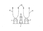
次に、カーテンを開閉するカーテン開閉装置の一例について説明する。このカーテン開閉装置117は、カーテンを巻き付けた始端側巻取ロール118と、始端巻取ロール118から引き出されるカーテンを折り返して反対方向に引き出すための第一のカウンタロール119と、第一のカウンタロール119から引き出されるカーテンを折り返して更に反対方向に引き出すための第二のカウンタロール120と、第二のカウンタロール120から引き出されるカーテンを巻き取る終端側巻取ロール121とを備え、始端側巻取ロール118と第二のカウンタロール120とを一側部に配置し、第一のカウンタロール119と終端側巻取ロール121とを対向する他側部に配置している。尚、始端側巻取ロール118の下方に第二のカウンタロール120を配置し、第一のカウンタロール119の下方に終端側巻取ロール121を配置している。尚、始端側巻取ロール118にはカーテンを巻き取る側に付勢するトルク・スプリングを設けており、終端側巻取ロール121を回転させるカーテン開閉用モータの駆動により、カーテンの開閉を制御する構成となっている。カーテンは、遮光性の高い遮光カーテン122と保温性の高い保温カーテン123とを繋ぎ合わせた構成となっており、始端側巻取ロール118から先に引き出される側に遮光カーテン122を配置し、遮光カーテン122に続いて保温カーテン123が引き出される構成となっている。尚、遮光カーテン122の引き出し側の先端には引き出し用ワイヤ124を接続しており、該引き出し用ワイヤ124の他端(遮光カーテン122とは反対側となる先端)を終端側巻取ロール121の外周に連結している。   Next, an example of a curtain opening / closing device that opens and closes the curtain will be described. The curtain opening / closing device 117 includes a start-end-side take-up roll 118 around which the curtain is wound, a first counter roll 119 for folding the curtain drawn out from the start-end take-up roll 118 and pulling it out in the opposite direction, and a first counter roll A second counter roll 120 for folding the curtain pulled out from 119 and pulling it out in the opposite direction; and a termination-side winding roll 121 for winding up the curtain pulled out from the second counter roll 120, The roll 118 and the second counter roll 120 are arranged on one side, and the first counter roll 119 and the terminal side take-up roll 121 are arranged on the other side facing each other. A second counter roll 120 is arranged below the start end side take-up roll 118, and a terminal end take-up roll 121 is arranged below the first counter roll 119. Note that the start-end side take-up roll 118 is provided with a torque spring that urges the curtain take-up side, and the curtain opening and closing motor 121 that rotates the end-side take-up roll 121 is driven to control the opening and closing of the curtain. It has a configuration. The curtain has a configuration in which a light-shielding curtain 122 having a high light-shielding property and a heat-insulating curtain 123 having a high heat-retaining property are connected to each other. A heat insulation curtain 123 is drawn out following the curtain 122. A leading wire 124 is connected to the leading end of the light shielding curtain 122, and the other end of the leading wire 124 (the tip opposite to the light shielding curtain 122) is connected to the end side winding roll 121. It is connected to the outer periphery.

従って、始端側巻取ロール118に遮光カーテン122及び保温カーテン123が巻き取られた状態では、始端側巻取ロール118から第一のカウンタロール119及び第二のカウンタロール120を介して終端側巻取ロール121まで引き出し用ワイヤ124が延びた状態となっており、カーテンが全開状態となる。そして、カーテン開閉用モータの駆動により終端側巻取ロール121を回転させると、引き出し用ワイヤ124を終端側巻取ロール121へ巻き付けながら始端側巻取ロール118から第一のカウンタロール119までの間の第一層125に遮光カーテン122を引き出した遮光状態になる。更に、カーテン開閉用モータの駆動により終端側巻取ロール121を回転させると、引き出し用ワイヤ124を終端側巻取ロール121へ巻き付けながら第一のカウンタロール119から第二のカウンタロール120までの間の第二層126に遮光カーテン122を引き出し、前記第一層125に保温カーテン123を引き出した第一保温状態になる。更に、カーテン開閉用モータの駆動により終端側巻取ロール121を回転させると、引き出し用ワイヤ124を終端側巻取ロール121へ巻き付けながら第二のカウンタロール120から終端側巻取ロール121までの間の第三層127に遮光カーテン122を引き出し、前記第一層125及び前記第二層126に保温カーテン123を引き出した第二保温状態になる。更に、カーテン開閉用モータの駆動により終端側巻取ロール121を回転させると、遮光カーテン122を終端側巻取ロール121へ巻き付けながら、前記第一層125から前記第三層127に全て保温カーテン123を引き出した第三保温状態になる。   Accordingly, in a state where the light shielding curtain 122 and the heat retaining curtain 123 are wound around the start end side winding roll 118, the end side winding is passed from the start end side winding roll 118 via the first counter roll 119 and the second counter roll 120. The drawing wire 124 is extended to the take-up roll 121, and the curtain is fully opened. Then, when the end-side winding roll 121 is rotated by driving the curtain opening / closing motor, the winding wire 124 is wound around the terminal-side winding roll 121 while the leading end-side winding roll 118 extends from the first counter roll 119. The light shielding curtain 122 is pulled out from the first layer 125 to be in a light shielding state. Further, when the end-side winding roll 121 is rotated by driving the curtain opening / closing motor, the winding wire 124 is wound around the end-side winding roll 121 and the first counter roll 119 to the second counter roll 120 are wound. Then, the light shielding curtain 122 is pulled out to the second layer 126 and the heat retaining curtain 123 is pulled out to the first layer 125, so that the first heat retaining state is obtained. Further, when the terminal winding roll 121 is rotated by driving the curtain opening / closing motor, the winding wire 124 is wound around the terminal winding roll 121 while the second counter roll 120 is connected to the terminal winding roll 121. The second curtain 127 is pulled out to the third layer 127, and the second curtain 126 is pulled out from the first layer 125 and the second layer 126. Further, when the end-side take-up roll 121 is rotated by driving the curtain opening / closing motor, all of the heat-insulating curtain 123 from the first layer 125 to the third layer 127 is wound while the light-shielding curtain 122 is wound around the end-side take-up roll 121. It becomes the third heat insulation state which pulled out.

よって、保温の必要がなく遮光のみを要するときには、前記遮光状態にする。また、ある程度保温を要するときには、前記第一保温状態にすることにより、保温カーテン123と遮光カーテン122との2層のカーテンで保温できる。以下、保温の必要の程度に対応して、第二保温状態及び第三保温状態に切り替えることができる。これにより、共通のカーテン開閉装置117(共通のカーテン開閉用モータ)により、遮光状態、保温状態及び該保温状態での保温の程度を切り替えることができ、カーテン開閉装置117を簡単な構成とすることができる。尚、遮光カーテン122を第一層125から第三層127にわたる程度に長く構成し、第一層125から第三層127まで順次遮光カーテン122を張設できる構成とすれば、日射の強度等に対応して遮光カーテン122の層の数を変更して所望の遮光度に設定することができる。また、異なる遮光率の遮光カーテン122を繋ぎ合わせた構成として、調節する遮光度を必要とする遮光度に設定できる構成とすればよい。あるいは、散乱性フィルムからなる遮光カーテン122や波長変換フィルムからなる遮光カーテン122を繋ぎ合わせた構成としてもよい。   Therefore, when there is no need for heat insulation and only light shielding is required, the light shielding state is set. Further, when it is necessary to keep the heat to some extent, the heat can be kept by the two-layer curtain of the heat-insulating curtain 123 and the light-shielding curtain 122 by setting the first heat-insulating state. Hereinafter, it can switch to a 2nd heat retention state and a 3rd heat retention state corresponding to the required grade of heat retention. As a result, the common curtain opening / closing device 117 (common curtain opening / closing motor) can be switched between the light shielding state, the heat retaining state, and the degree of heat retaining in the heat retaining state, and the curtain opening / closing device 117 has a simple configuration. Can do. In addition, if the light shielding curtain 122 is configured to be long enough to extend from the first layer 125 to the third layer 127 and the light shielding curtain 122 can be sequentially stretched from the first layer 125 to the third layer 127, the intensity of solar radiation can be increased. Correspondingly, the desired number of shades can be set by changing the number of layers of the shade curtain 122. Moreover, what is necessary is just to set it as the structure which can set to the light-blocking degree which requires the light-blocking degree to adjust as the structure which connected the light-shielding curtain 122 of a different light-shielding rate. Or it is good also as a structure which connected the light shielding curtain 122 which consists of a scattering film, and the light shielding curtain 122 which consists of a wavelength conversion film.

また、天候等により日射量が不足するとき、夜間等に栽培室1内に設けた照明装置を点灯させて植物へ補光することができる。一方、所望の収穫量を得るために、植物が光合成を行って所望の光合成産物量を得る必要がある。そこで、天気予報等の気象データから積算日射量を推定し、推定された積算日射量に基づいてその時点での積算日射量が不足すると判断するときは、照明装置により補光することができる。具体的には、収穫予定日までの日数から1日で必要な光合成産物量を演算し、この光合成産物量を得るのに必要な積算日射量に満たない日は、所望の積算日射量となるよう夜間に補光することができる。尚、日射量と光合成産物量との関係特性を予め把握し、この関係特性に基づいて前記必要な積算日射量を演算する。尚、前記気象データに代えて、日射量計により積算日射量を計測してもよい。   Further, when the amount of solar radiation is insufficient due to the weather or the like, the lighting device provided in the cultivation room 1 can be turned on at night to supplement the plant. On the other hand, in order to obtain a desired yield, a plant needs to perform photosynthesis to obtain a desired amount of photosynthesis product. Therefore, when the integrated solar radiation amount is estimated from meteorological data such as a weather forecast and it is determined that the cumulative solar radiation amount at that time is insufficient based on the estimated integrated solar radiation amount, the lighting device can supplement the light. Specifically, the amount of photosynthetic product necessary for one day is calculated from the number of days until the scheduled harvest date, and the day when the amount of accumulated solar radiation necessary to obtain this amount of photosynthetic product is not reached is the desired accumulated solar radiation amount. It can be supplemented at night. A relational characteristic between the amount of solar radiation and the amount of photosynthetic products is grasped in advance, and the necessary integrated solar radiation amount is calculated based on this relational characteristic. In addition, it may replace with the said weather data and may measure an integrated solar radiation amount with a solar radiation meter.

また、補光に際しては、青色光を補光することが望ましい。青色光により、植物の葉の気孔が開き易くなるので、光合成の促進効果を高めることができる。尚、補光中には灌水量を多く設定することにより、気孔が開くことにより植物の蒸散が高まっても植物の水分量を所望に維持することができる。   In addition, it is desirable to supplement blue light when supplementing light. The blue light makes it easy to open the pores of the plant leaves, so that the effect of promoting photosynthesis can be enhanced. It should be noted that by setting a large amount of irrigation during supplementary light, the moisture content of the plant can be maintained as desired even if the transpiration of the plant increases due to the opening of the pores.

尚、植物の呼吸量が増加すると、植物の光合成産物量の消費が大きくなるので、この呼吸量により目標とする光合成量を補正する構成とすることができる。呼吸量は、温度の上昇により多くなるので、日射量や栽培室1内の室温により推定することができる。従って、日没後の室温が低下したときに補光を行えば、効率良く光合成産物量を得ることができる。尚、呼吸量は、1日における温度変化又は日射量変化に基づいて高精度で推定することが望ましい。   In addition, since the consumption of the photosynthesis product of a plant will increase when the respiration rate of a plant increases, it can be set as the structure which correct | amends the target photosynthesis amount by this respiration rate. Since the respiration rate increases as the temperature rises, it can be estimated from the amount of solar radiation and the room temperature in the cultivation room 1. Therefore, the amount of photosynthetic product can be efficiently obtained by supplementing light when the room temperature after sunset falls. In addition, it is desirable to estimate the respiration rate with high accuracy based on the temperature change or the solar radiation amount change in one day.

また、日射量、二酸化炭素濃度及び室温から、1日の日照時間帯の各々の時間における光合成速度と呼吸速度を推定し、光合成速度による光合成産物量の増加速度が呼吸速度による光合成産物量の消化速度を下回るとき、前記増加速度と前記減少速度との差から時間的に積分して減少した光合成産物量を演算することができる。この減少した光合成産物量を得るべく、日没後に補光する。尚、日没の判断は、時刻により行ったり、栽培室1外に設けた日射量センサ(日射量が0となったとき)により行うことができる。補光に必要な時間は、前記減少した光合成産物量を、補光の強度と植物の光利用効率(1molあたりの光で同化できる二酸化炭素の量(mol))とで除する演算により求めることができる。あるいは、補光する時間を予め設定し、前記減少した光合成産物量に基づいて補光の強度を演算し、照明の点灯数の変更等により補光の強度を調節してもよい。   In addition, the photosynthetic rate and respiration rate during each day of the day's sunshine hours are estimated from the amount of solar radiation, carbon dioxide concentration, and room temperature. When the speed is lower than the speed, the amount of the photosynthetic product that is decreased by integrating over time can be calculated from the difference between the increasing speed and the decreasing speed. In order to obtain this reduced amount of photosynthetic product, the light is supplemented after sunset. The determination of sunset can be made according to the time of day or by using a solar radiation amount sensor provided outside the cultivation room 1 (when the solar radiation amount becomes 0). The time required for supplementary light is determined by calculating the reduced amount of photosynthetic product by the intensity of supplementary light and the light utilization efficiency of the plant (the amount of carbon dioxide that can be assimilated with light per mole (mol)). Can do. Alternatively, the supplementary light may be set in advance, the supplementary light intensity may be calculated based on the reduced amount of the photosynthetic product, and the supplementary light intensity may be adjusted by changing the number of lights.

尚、日の出前に補光することもできる。このとき、日の出時刻よりも補光に必要な時間前の時刻から、日の出時刻まで補光をすればよい。日没後よりも日の出前の方が室温が低下しているので、特に夏期においては、補光時の植物の呼吸量を抑えることができ、効率良く光合成産物量を得ることができる。尚、補光の開始時刻は、日の出時刻よりも一定時間前に設定してもよい。   It is also possible to supplement light before sunrise. At this time, the light supplement may be performed from the time before the sunrise time to the sunrise time from the time before the supplementary light. Since the room temperature is lower before sunrise than after sunset, especially during the summer, the respiration rate of plants during supplementary light can be suppressed, and the amount of photosynthetic product can be obtained efficiently. The supplementary light start time may be set a certain time before the sunrise time.

栽培室1内の湿度の検出に基づいて所望の湿度となるよう栽培室1内の加湿機を制御する構成とすることができる。加湿機は、細霧を噴霧する構成とすることができ、細霧冷房装置で構成することもできる。そして、日射量センサの検出等に基づいて植物の蒸散量を推定し、加湿機により必要な蒸発量に相当する細霧を噴霧すれば、栽培室1内の湿度を高精度で制御できる。これにより、湿度過多による植物の病気の発生を防止できると共に、細霧の噴霧量を抑えることによりランニングコストを低減することができる。尚、細霧の噴霧量の調節にあたっては、栽培室1内に設けた複数の噴霧ノズルのうちの一部の噴霧ノズルのみ噴霧に使用する等して調節を行うことができる。   It can be set as the structure which controls the humidifier in the cultivation room 1 so that it may become desired humidity based on the detection of the humidity in the cultivation room 1. FIG. The humidifier can be configured to spray fine mist, or can be configured with a fine mist cooling device. And if the transpiration | evaporation amount of a plant is estimated based on the detection of a solar radiation amount sensor, etc. and the fine mist equivalent to the evaporation amount required by a humidifier is sprayed, the humidity in the cultivation room 1 can be controlled with high precision. Thereby, it is possible to prevent the occurrence of plant diseases due to excessive humidity, and it is possible to reduce the running cost by suppressing the spray amount of fine mist. In addition, in adjusting the spray amount of the fine mist, the adjustment can be performed by using only some of the spray nozzles provided in the cultivation room 1 for spraying.

また、栽培室1の屋根には、天窓開閉モータの駆動により開閉する天窓を設けている。天窓が閉じた状態であることを検出する天窓閉センサを設け、通常は、天窓閉センサが天窓の閉状態を検出するまで天窓開閉モータを天窓が閉じる側へ駆動し、天窓を閉状態にする。栽培室1内の温度(室温)を測定する室温センサの検出に基づき、栽培室1内の室温が目標温度よりも高い場合には、制御装置により、室温と目標温度との差に基づいて天窓の目標開度を演算し、該目標開度に対応する必要な作動時間で天窓が開く側へ天窓開閉モータを駆動し、栽培室1内の温度を低下させるべく天窓を所望の開度で開く構成である。そして、天窓を開いた状態でも、室温と目標温度との差に基づいて天窓の目標開度を逐次演算して更新し、該目標開度に対応する必要な作動時間で天窓が開く側又は閉じる側へ天窓開閉モータを駆動し、天窓を作動させる構成となっている。但し、天窓を開いた状態から更に天窓を作動させる際、天窓の目標開度が所定開度以下(例えば、10%以下)のときは、天窓閉センサが天窓の閉状態を検出するまで天窓開閉モータを駆動して天窓を一旦閉じ、前記目標開度に対応する必要な作動時間で天窓が開く側へ天窓開閉モータを駆動し、天窓を目標開度で開く零点復帰制御を実行する構成である。これにより、天窓の開度を検出する高価なセンサが不要で、低コストで天窓の開度を高精度に制御でき、室温を良好に制御できる。特に、室温と目標温度との差が小さく、天窓の目標開度が所定開度以下のときに、天窓の開度を高精度に制御するので、天窓の開度が大きすぎることにより室温が急激に目標温度よりも低温にまで低下することを防止し、栽培植物に悪影響を与えることを防止できる。従来は、天窓の目標開度が変更される度に、現在の天窓の開度と目標開度との関係から該目標開度となる側に必要な作動時間で天窓を作動させているので、前記作動時間による実際の天窓の開度の誤差が累積し、天窓の開度が不適正になるおそれがある。尚、天窓の目標開度が所定開度以下のときに上述の零点復帰制御を実行する構成に代えて、外気温センサが検出する外気温が所定温度以下(例えば、摂氏10度以下)のときに上述の零点復帰制御を実行する構成としたり、天窓の目標開度が所定開度以下で且つ外気温センサが検出する外気温が所定温度以下のときに上述の零点復帰制御を実行する構成としたりしてもよい。また、栽培室1外の風向や風速に基づき、天窓の開口側に向かって風が吹き込むときや風速が大きいときには、上述の零点復帰制御を実行する構成としてもよい。あるいは、天窓の目標開度や外気温に基づく零点復帰制御において、風向又は風速もしくは風向と風速の両者に基づき、天窓の開口側に向かって風が吹き込むときや風速が大きいときには、天窓の目標開度の前記所定開度又は外気温の前記所定温度を大きい値に補正する構成としてもよい。風向又は風速の測定にあたっては、栽培室1外の屋根部に風向計や風速計を設ければよい。また、天窓を最大開度に開いた状態であることを検出する天窓最大開度センサを設け、天窓を最大開度にまで開くときは、天窓が最大開度に開いた状態であることを天窓最大開度センサが検出するまで天窓開閉モータを駆動する構成としてもよい。   Moreover, the roof of the cultivation room 1 is provided with a skylight that opens and closes by driving a skylight opening and closing motor. A skylight closing sensor is provided to detect that the skylight is closed. Normally, the skylight opening / closing motor is driven to close the skylight until the skylight closing sensor detects that the skylight is closed, and the skylight is closed. . When the room temperature in the cultivation room 1 is higher than the target temperature based on the detection of the room temperature sensor that measures the temperature (room temperature) in the cultivation room 1, the control device causes the skylight to be based on the difference between the room temperature and the target temperature. The target opening is calculated, and the skylight opening / closing motor is driven to the side where the skylight opens in the required operating time corresponding to the target opening, and the skylight is opened at the desired opening to lower the temperature in the cultivation room 1 It is a configuration. Even when the skylight is open, the target opening of the skylight is sequentially calculated and updated based on the difference between the room temperature and the target temperature, and the skylight is opened or closed at the required operating time corresponding to the target opening. The skylight opening / closing motor is driven to the side to operate the skylight. However, when operating the skylight further from the state where the skylight is open, if the target opening of the skylight is below a predetermined opening (for example, 10% or less), the skylight is opened and closed until the skylight closing sensor detects the skylight closed state. It is configured to drive the motor to close the skylight once, drive the skylight opening / closing motor to the side where the skylight opens in the required operating time corresponding to the target opening, and execute zero return control to open the skylight at the target opening . Thereby, an expensive sensor for detecting the opening of the skylight is unnecessary, the opening of the skylight can be controlled with high accuracy at low cost, and the room temperature can be controlled well. In particular, when the difference between the room temperature and the target temperature is small and the target opening of the skylight is less than a predetermined opening, the opening of the skylight is controlled with high accuracy. It is possible to prevent the temperature from lowering to a lower temperature than the target temperature, and to prevent adverse effects on the cultivated plants. Conventionally, every time the target opening of the skylight is changed, the skylight is operated with the required operating time on the side that becomes the target opening from the relationship between the current opening of the skylight and the target opening, Errors in the actual opening of the skylight due to the operating time may accumulate, and the opening of the skylight may become inappropriate. When the outside air temperature detected by the outside air temperature sensor is not more than the predetermined temperature (for example, not more than 10 degrees Celsius) instead of the above-described configuration in which the zero point return control is executed when the target opening of the skylight is not more than the predetermined opening. The above-described zero-point return control is executed, or the above-described zero-point return control is executed when the target opening of the skylight is not more than a predetermined opening and the outside air temperature detected by the outside air temperature sensor is not more than the predetermined temperature. Or you may. Moreover, it is good also as a structure which performs the above-mentioned zero point return control, when a wind blows toward the opening side of a skylight based on the wind direction and wind speed outside the cultivation room 1, or when a wind speed is large. Alternatively, in the zero point return control based on the target opening of the skylight and the outside air temperature, when the wind blows toward the opening side of the skylight or the wind speed is high based on the wind direction or the wind speed or both the wind direction and the wind speed, the target opening of the skylight is increased. The predetermined opening degree or the predetermined temperature of the outside air temperature may be corrected to a large value. In measuring the wind direction or wind speed, an anemometer or anemometer may be provided on the roof outside the cultivation room 1. In addition, a skylight maximum opening sensor that detects that the skylight is opened to the maximum opening is provided, and when the skylight is opened to the maximum opening, the skylight is displayed to indicate that the skylight is open to the maximum opening. It is good also as a structure which drives a skylight opening / closing motor until a maximum opening degree sensor detects.

また、栽培室1の妻部に、風力に応じて開閉する開閉窓を設けることができる。この開閉窓は、開閉窓用スプリングにより閉じる側に付勢され、通常は閉じた状態であるが、栽培室1内の風が強いと開閉窓用スプリングに抵抗して開き、栽培室1内の風を外部に逃がす構成となっている。これにより、栽培室1の隙間から栽培室1内に入り込んだ風により栽培室1が破損することを防止でき、特にビニールハウス等の軟弱な構造の栽培室1に有効である。   Moreover, the opening / closing window which opens and closes according to wind force can be provided in the wife part of the cultivation room 1. This open / close window is urged toward the closing side by the open / close window spring, and is normally closed. However, when the wind in the cultivation room 1 is strong, it opens against the open / close window spring. It is configured to let the wind escape to the outside. Thereby, it can prevent that the cultivation room 1 is damaged with the wind which entered the cultivation room 1 from the clearance gap between the cultivation rooms 1, and is effective especially for the cultivation room 1 of soft structures, such as a vinyl house.

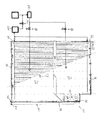
ところで、栽培ベッド5となるロックウールの底面と側方の四方を囲む発泡製の断熱体128を設けている。栽培ベッド5と断熱体128との間には防根シート129を設け、架台から防根シート129を介して栽培ベッド5を支持している。防根シート129は、根を通過させないが、栽培ベッド5からの排液を通過し得る構造となっている。断熱体128の左右中央には、長手方向に延びる排液溝130を設けている。架台には左右の断熱体支持軸を上下2段に設け、上下何れかの断熱体支持軸上に断熱体支持板を載せ、断熱体支持板上に断熱体128を載せて支持する構成となっている。従って、断熱体支持板の高さを切り替えることにより、断熱体128を、防根シート129に接触して栽培ベッド5を囲む高位と栽培ベッド5から下方に離れた低位とに高さ変更できる。これにより、例えば、夏期は、断熱体128を低位にして通風による栽培ベッド5の冷却効果及び病害発生の防止を図ることができ、冬期は、断熱体128を高位にして栽培ベッド5の保温効果を図ることができる。尚、上述では上下2段の断熱体支持軸により断熱体128の高さを変更可能に構成したが、例えばラック及びピニオン等を備える昇降装置により断熱体128の高さを変更する構成としてもよい。また、前記昇降装置を設ける場合、栽培ベッド5の温度を検出するベッド温度センサに基づき、栽培ベッド5の温度に対応して温度が高いときには断熱体128を低位にする構成としてもよい。   By the way, the foam heat insulation 128 surrounding the bottom face of rock wool used as the cultivation bed 5 and four sides is provided. A root prevention sheet 129 is provided between the cultivation bed 5 and the heat insulator 128, and the cultivation bed 5 is supported from the mount via the root prevention sheet 129. The root-preventing sheet 129 has a structure that does not allow the root to pass but allows the drainage from the cultivation bed 5 to pass. A drainage groove 130 extending in the longitudinal direction is provided at the left and right center of the heat insulator 128. The frame has a structure in which left and right heat insulator support shafts are provided in two upper and lower stages, a heat insulator support plate is placed on either the upper or lower heat insulator support shaft, and a heat insulator 128 is placed on and supported by the heat insulator support plate. ing. Therefore, by switching the height of the heat insulating support plate, the heat insulating body 128 can be changed in height between the high level surrounding the cultivation bed 5 by contacting the root-proof sheet 129 and the low level separated downward from the cultivation bed 5. Thereby, for example, in the summer season, the heat insulation body 128 can be lowered to prevent the cultivation bed 5 from being cooled and to prevent the occurrence of diseases by ventilation. In the winter season, the heat insulation body 128 can be raised to the heat insulation effect of the cultivation bed 5. Can be achieved. In the above description, the height of the heat insulator 128 can be changed by the upper and lower two-stage heat insulator support shafts. However, for example, the height of the heat insulator 128 may be changed by a lifting device including a rack and a pinion. . Moreover, when providing the said raising / lowering apparatus, based on the bed temperature sensor which detects the temperature of the cultivation bed 5, when the temperature is high corresponding to the temperature of the cultivation bed 5, it is good also as a structure which makes the heat insulation 128 low.

尚、図2では、架台により栽培ベッド5を地面から支持した構成を表しているが、吊下支持部材により栽培ベッド5を上方から吊り下げて支持する構成としてもよい。このとき、栽培ベッド5及び植物を囲む包囲フィルムを設けることにより、植物近傍のみを局所的に暖房又は冷房もしくは防除でき、暖房又は冷房もしくは防除のランニングコストを低減できる。栽培ベッド5の下方となる包囲フィルムの下部には、防除作業により包囲フィルムの内面に付着した薬液を排出する排出孔を設け、排出孔から落下する薬液を回収して再利用することもできる。尚、包囲フィルム内で植物近傍に局所的に炭酸ガスを供給することもできる。   In addition, in FIG. 2, although the structure which supported the cultivation bed 5 from the ground with the mount frame was represented, it is good also as a structure which suspends and supports the cultivation bed 5 from upper direction with a suspension support member. At this time, by providing the surrounding film surrounding the cultivation bed 5 and the plant, only the vicinity of the plant can be locally heated, cooled or controlled, and the running cost of heating, cooling or controlling can be reduced. A discharge hole for discharging the chemical solution attached to the inner surface of the surrounding film by the control operation is provided in the lower part of the surrounding film below the cultivation bed 5, and the chemical solution falling from the discharge hole can be collected and reused. In addition, carbon dioxide gas can also be supplied locally in the vicinity of the plant in the surrounding film.

以上により、この栽培施設は、降雨を検知する降雨センサ(116)と、雨水を回収する雨水回収装置(111)と、雨水回収装置で回収された雨水を栽培用の養液供給装置(7)の原水タンク(44)へ供給する雨水供給経路(114)とを設け、降雨センサ(116)が降雨を検知して所定時間後から降雨を検知しなくなるまでの間のみ、雨水回収装置(111)で回収された雨水を養液供給装置(7)の原水タンク(44)へ供給する制御装置を設けている。   As described above, this cultivation facility includes a rain sensor (116) that detects rain, a rain water collection device (111) that collects rain water, and a nutrient solution supply device (7) for cultivation of rain water collected by the rain water collection device. A rainwater supply path (114) for supplying water to the raw water tank (44) is provided, and the rainwater recovery device (111) is used only after the rain sensor (116) detects the rain and no longer detects the rain after a predetermined time. The control apparatus which supplies the rainwater collect | recovered by (4) to the raw | natural water tank (44) of a nutrient solution supply apparatus (7) is provided.

よって、降雨が始まって第一の所定時間後、雨水がある程度貯留されてから該雨水を原水タンク(44)へ供給するので、簡単で且つ低コストな構成で、雨水内の不純物を原水タンク(44)へ極力供給しないようにでき、養液供給装置(7)から植物へ適正な養液を供給でき、良好な栽培が行える。   Therefore, since rainwater is stored to some extent after the first predetermined time from the start of rainfall, the rainwater is supplied to the raw water tank (44), so that impurities in the rainwater can be removed from the raw water tank (with a simple and low-cost configuration). 44) can be prevented from being supplied as much as possible, an appropriate nutrient solution can be supplied from the nutrient solution supply device (7) to the plant, and good cultivation can be performed.

また、制御装置は、降雨センサ(116)の検知に拘らず雨水回収装置(111)で回収された雨水を原水タンク(44)へ供給せず、原水タンク(44)内の水位の所定以下の低下に伴って別の水源から原水タンク(44)へ水を供給する雨水不使用形態と、降雨センサ(116)の検知に拘らず雨水回収装置(111)で回収された雨水を原水タンク(44)へ供給し、原水タンク(44)内の水位が所定以下に低下したときには別の水源から原水タンク(44)へ水を供給する雨水優先形態と、原水タンク(44)内の水位が所定以下に低下したときに雨水回収装置(111)で回収された雨水と別の水源からの水を共に供給する雨水併用形態とに、切替可能な構成としている。   In addition, the control device does not supply the rainwater collected by the rainwater collecting device (111) to the raw water tank (44) regardless of the detection by the rain sensor (116), and the water level in the raw water tank (44) is below a predetermined level. A rainwater non-use form in which water is supplied from another water source to the raw water tank (44) in accordance with the decrease and the rainwater collected by the rainwater collecting device (111) regardless of the detection by the rain sensor (116) ) And when the water level in the raw water tank (44) drops below a predetermined level, the rainwater priority mode is to supply water from another water source to the raw water tank (44), and the water level in the raw water tank (44) is below the predetermined level. The rainwater collected by the rainwater collecting device (111) and the rainwater combined use mode for supplying water from another water source together when the rainwater drops to a rainwater collecting device (111) can be switched.

よって、雨水不使用状態に切り替えることにより、例えば雨量が少ないときや雨水に不純物が多いとき、雨水を原水タンク(44)へ供給しないようにできる。また、雨水優先状態に切り替えることにより、雨水を極力使用しながら、雨量が少なくても原水タンク(44)内に必要な水量を確保することができる。また、雨水併用状態に切り替えることにより、雨水の使用割合を抑えることができ、原水タンク(44)への不純物の混入を抑えることができる。   Therefore, by switching to the rainwater non-use state, for example, when the amount of rain is small or the rainwater has a large amount of impurities, rainwater can be prevented from being supplied to the raw water tank (44). In addition, by switching to the rainwater priority state, it is possible to secure the necessary amount of water in the raw water tank (44) even if the amount of rain is small while using rainwater as much as possible. Moreover, by switching to a rainwater combined use state, the usage rate of rainwater can be suppressed, and mixing of impurities into the raw water tank (44) can be suppressed.

また、養液供給装置(7)からの養液が植物へ給液された後の排液を回収する構成とし、養液供給装置(7)から植物への給液を開始してから給液を終了するまでの間は、雨水回収装置(111)で回収された雨水を原水タンク(44)へ供給しない構成としている。   Moreover, it is set as the structure which collect | recovers the drainage liquid after the nutrient solution from a nutrient solution supply apparatus (7) was supplied to a plant, and liquid supply after starting the liquid supply to a plant from a nutrient solution supply apparatus (7) Until the operation is terminated, the rainwater collected by the rainwater collecting device (111) is not supplied to the raw water tank (44).

よって、養液供給装置(7)が植物へ給液している間に雨水が原水タンク(44)へ供給されることにより、植物へ供給される養液が不安定になることを防止でき、養液供給装置(7)から植物へ適正な養液を供給でき、良好な栽培が行える。   Therefore, by supplying rainwater to the raw water tank (44) while the nutrient solution supply device (7) is supplying the plant, it is possible to prevent the nutrient solution supplied to the plant from becoming unstable, An appropriate nutrient solution can be supplied to the plant from the nutrient solution supply device (7), and good cultivation can be performed.

また、雨水回収装置(111)には、雨水を回収する樋(96)を備え、該樋(96)を、雨水を養液供給装置(7)へ供給しないときに、養液供給装置(7)からの養液が植物へ給液された後の排液の排出樋として兼用する構成としている。   The rainwater recovery device (111) is provided with a trough (96) for collecting rainwater, and when the rainwater is not supplied to the nutrient solution supply device (7), the nutrient solution supply device (7) is provided. ) From which the nutrient solution is supplied to the plant.

よって、雨水を回収する樋(96)を排液の排出樋として兼用でき、簡単で且つ低コストな構造とすることができる。 また、複数に区画された栽培エリア(97)のうちの一部の栽培エリア(97)へのみ養液を供給可能に構成し、前記一部の栽培エリア(97)からの排液を、当該一部の栽培エリア(97)でのみ再利用し、他の栽培エリア(97)へは供給しない構成としている。   Therefore, the dredger (96) for collecting rainwater can also be used as a drain for drainage, and a simple and low-cost structure can be achieved. Moreover, it comprises so that a nutrient solution can be supplied only to a part of cultivation area (97) among the cultivation areas (97) divided into a plurality, and the drainage from the part of the cultivation area (97) It is configured to be reused only in some cultivation areas (97) and not supplied to other cultivation areas (97).

よって、仮に排液を回収する一部の栽培エリア(97)で病害が発生したとしても、回収した排液を他の栽培エリア(97)で再利用しないので、他の栽培エリア(97)への病害の蔓延を防止できる。   Therefore, even if a disease occurs in a part of the cultivation area (97) where the drainage is collected, the collected drainage is not reused in the other cultivation area (97). Can prevent the spread of disease

Claims (6)

降雨を検知する降雨センサ(116)と、雨水を回収する雨水回収装置(111)と、雨水回収装置で回収された雨水を栽培用の養液供給装置(7)の原水タンク(44)へ供給する雨水供給経路(114)とを設け、降雨センサ(116)が降雨を検知して所定時間後から降雨を検知しなくなるまでの間のみ、雨水回収装置(111)で回収された雨水を養液供給装置(7)の原水タンク(44)へ供給する制御装置を設けた栽培施設。   A rain sensor (116) for detecting rain, a rain water recovery device (111) for recovering rain water, and supplying rain water recovered by the rain water recovery device to the raw water tank (44) of the nutrient solution supply device (7) for cultivation A rainwater supply path (114) is provided, and the rainwater collected by the rainwater recovery device (111) is nourished only after the rain sensor (116) detects the rain and until no rain is detected after a predetermined time. A cultivation facility provided with a control device for supplying the raw water tank (44) of the supply device (7). 制御装置は、降雨センサ(116)の検知に拘らず雨水回収装置(111)で回収された雨水を原水タンク(44)へ供給せず、原水タンク(44)内の水位の所定以下の低下に伴って別の水源から原水タンク(44)へ水を供給する雨水不使用形態と、降雨センサ(116)の検知に拘らず雨水回収装置(111)で回収された雨水を原水タンク(44)へ供給し、原水タンク(44)内の水位が所定以下に低下したときには別の水源から原水タンク(44)へ水を供給する雨水優先形態と、原水タンク(44)内の水位が所定以下に低下したときに雨水回収装置(111)で回収された雨水と別の水源からの水を共に供給する雨水併用形態とに、切替可能な構成とした請求項1に記載の栽培施設。   The control device does not supply the rainwater collected by the rainwater collecting device (111) to the raw water tank (44) regardless of the detection by the rain sensor (116), so that the water level in the raw water tank (44) is lowered below a predetermined level. Accordingly, the rainwater is not used to supply water from another water source to the raw water tank (44), and the rainwater collected by the rainwater collecting device (111) is detected to the raw water tank (44) regardless of the detection of the rain sensor (116). When the water level in the raw water tank (44) is reduced to a predetermined level or less, the rain water priority mode for supplying water from another water source to the raw water tank (44) and the water level in the raw water tank (44) lowers to a predetermined level or less. The cultivation facility according to claim 1, which is configured to be switchable between a rainwater collected by the rainwater collecting device (111) and a rainwater combined form for supplying water from another water source. 養液供給装置(7)からの養液が植物へ給液された後の排液を回収する構成とし、養液供給装置(7)から植物への給液を開始してから給液を終了するまでの間は、雨水回収装置(111)で回収された雨水を原水タンク(44)へ供給しない構成とした請求項1又は請求項2に記載の栽培施設。   It is set as the structure which collect | recovers the drainage liquid after the nutrient solution from a nutrient solution supply apparatus (7) was supplied to a plant, and after supplying liquid to a plant from a nutrient solution supply apparatus (7), it ends supply Until then, the cultivation facility according to claim 1 or 2, wherein rainwater collected by the rainwater collection device (111) is not supplied to the raw water tank (44). 雨水回収装置(111)には、雨水を回収する樋(96)を備え、該樋(96)を、雨水を養液供給装置(7)へ供給しないときに、養液供給装置(7)からの養液が植物へ給液された後の排液の排出樋として兼用する構成とした請求項1から請求項3の何れか1項に記載の栽培施設。   The rainwater recovery device (111) includes a trough (96) for collecting rainwater, and the trough (96) is supplied from the nutrient solution supply device (7) when rainwater is not supplied to the nutrient solution supply device (7). The cultivation facility according to any one of claims 1 to 3, wherein the nourishing solution is also used as a drain for discharging the drainage liquid after being fed to the plant. 複数に区画された栽培エリア(97)のうちの一部の栽培エリア(97)へのみ養液を供給可能に構成し、前記一部の栽培エリア(97)からの排液を、当該一部の栽培エリア(97)でのみ再利用し、他の栽培エリア(97)へは供給しない構成とした請求項1から請求項4の何れかに記載の栽培施設。   It comprises so that a nutrient solution can be supplied only to a part of cultivation area (97) in the cultivation area (97) divided into plurality, and the drainage from the part of cultivation area (97) The cultivation facility according to any one of claims 1 to 4, wherein the cultivation facility is reused only in the cultivation area (97) and not supplied to other cultivation areas (97). 前記養液供給装置(7)から供給される薬液によって作物を栽培する栽培ベッド(5)を複数配置する栽培スペース(6)を有すると共に、暖房機や加湿機等により温度及び湿度等の室内環境が管理される温室である栽培室(1)内の天井部にカーテンを設け、該カーテンを開閉するカーテン開閉装置(117)を、カーテンを巻き付けた始端側巻取ロール(118)と、始端巻取ロール(118)から引き出されるカーテンを折り返して反対方向に引き出すためのカウンタロール(119,120)と、カウンタロール(119,120)から引き出されるカーテンを巻き取る終端側巻取ロール(121)とを備えて構成し、カーテンは、遮光性のある遮光カーテン(122)と保温性のある保温カーテン(123)とを繋ぎ合わせて構成され、始端側巻取ロール(118)から先に引き出される側に遮光カーテン(122)を配置して遮光カーテン(122)に続いて保温カーテン(123)が引き出される構成とすると共に、遮光カーテン(122)の引き出し側の先端には引き出し用ワイヤ(124)を接続し、始端側巻取ロール(118)に遮光カーテン(122)及び保温カーテン(123)が巻き取られたカーテン全開状態と、始端側巻取ロール(118)から遮光カーテン(122)のみを引き出した遮光状態と、終端側巻取ロール(121)に遮光カーテン(122)を巻き取って保温カーテン(123)のみを引き出した保温状態とに切替可能に構成した請求項1から請求項5の何れかに記載の栽培施設。 It has a cultivation space (6) for arranging a plurality of cultivation beds (5) for cultivating crops with the chemical solution supplied from the nutrient solution supply device (7), and an indoor environment such as temperature and humidity by a heater or a humidifier. A curtain opening / closing device (117) for opening and closing the curtain is provided on the ceiling in the cultivation room (1), which is a greenhouse controlled by a starter winding roll (118) around which the curtain is wound, and a starter winding A counter roll (119, 120) for folding the curtain drawn from the take-up roll (118) and pulling it out in the opposite direction; and a terminal-side take-up roll (121) for taking up the curtain drawn from the counter roll (119, 120) The curtain is constructed by connecting a light shielding curtain (122) having a light shielding property and a heat retaining curtain (123) having a heat retaining property. The light-shielding curtain (122) is arranged on the side pulled out first from the start-end side take-up roll (118), and the heat-insulating curtain (123) is drawn out after the light-shielding curtain (122). 122) a drawing wire (124) is connected to the leading end of the pulling side of 122), and the curtain is fully opened in which the light-shielding curtain (122) and the heat-insulating curtain (123) are wound around the winding winding roll (118). A light-shielding state in which only the light-shielding curtain (122) is pulled out from the side winding roll (118), and a heat-insulating state in which only the heat-insulating curtain (123) is pulled out by winding the light-shielding curtain (122) around the terminal-side winding roll (121). The cultivation facility according to any one of claims 1 to 5, wherein the cultivation facility is configured to be switchable.
JP2014017422A 2014-01-31 2014-01-31 Cultivation facility Expired - Fee Related JP6056779B2 (en)

Priority Applications (1)

Application Number Priority Date Filing Date Title
JP2014017422A JP6056779B2 (en) 2014-01-31 2014-01-31 Cultivation facility

Applications Claiming Priority (1)

Application Number Priority Date Filing Date Title
JP2014017422A JP6056779B2 (en) 2014-01-31 2014-01-31 Cultivation facility

Related Child Applications (1)

Application Number Title Priority Date Filing Date
JP2016237802A Division JP6428752B2 (en) 2016-12-07 2016-12-07 Cultivation facility

Publications (3)

Publication Number Publication Date
JP2015142534A JP2015142534A (en) 2015-08-06
JP2015142534A5 JP2015142534A5 (en) 2015-12-17
JP6056779B2 true JP6056779B2 (en) 2017-01-11

Family

ID=53888091

Family Applications (1)

Application Number Title Priority Date Filing Date
JP2014017422A Expired - Fee Related JP6056779B2 (en) 2014-01-31 2014-01-31 Cultivation facility

Country Status (1)

Country Link
JP (1) JP6056779B2 (en)

Families Citing this family (2)

* Cited by examiner, † Cited by third party
Publication number Priority date Publication date Assignee Title
CN106576557B (en) * 2016-11-29 2023-08-01 四川大学 Water and fertilizer integrated drip irrigation system based on intelligent rain collecting greenhouse
JOP20190171A1 (en) * 2017-06-14 2019-07-09 Grow Solutions Tech Llc Systems and methods for providing air flow in a grow pod

Family Cites Families (7)

* Cited by examiner, † Cited by third party
Publication number Priority date Publication date Assignee Title
JPS49130039U (en) * 1973-03-13 1974-11-08
JPS632464U (en) * 1986-06-24 1988-01-09
JPS6331770U (en) * 1986-08-13 1988-03-01
JPH01112928A (en) * 1987-10-23 1989-05-01 Yanmar Agricult Equip Co Ltd Hydroponic culture apparatus
JP2948183B2 (en) * 1997-12-27 1999-09-13 株式会社石井機械製作所 Greenhouse with water storage tank
JP5085378B2 (en) * 2008-03-11 2012-11-28 株式会社 フジネット Wall greening system
JP3152366U (en) * 2009-05-15 2009-07-30 直 安里 greenhouse

Also Published As

Publication number Publication date
JP2015142534A (en) 2015-08-06

Similar Documents

Publication Publication Date Title
JP6350726B2 (en) Mobile work vehicle
JP6460161B2 (en) Mobile vehicle for cultivation facilities
JP6673442B2 (en) Fruit harvesting system
JP6123621B2 (en) Cultivation equipment
JP6256821B2 (en) Agricultural house
JP4692010B2 (en) Cultivation facility
JP5407056B2 (en) Plant cultivation equipment
CN104115705A (en) Greenhouse achieving warmth in winter
JP6428752B2 (en) Cultivation facility
JP6439294B2 (en) Cultivation facility
JP6056779B2 (en) Cultivation facility
KR101892163B1 (en) System for controlling a smart greenhouse
KR20150084103A (en) Hybrid cooling & heating system of a green house
JP2016010374A5 (en)
JP6435664B2 (en) Nutrient solution supply device
JP2014124167A (en) Cultivation facility
CN112056125A (en) Automatic exhaust system of closed big-arch shelter of agricultural
JP2015142534A5 (en)
JP2009044999A (en) Plant cultivation controller
JP6406007B2 (en) Cultivation facility
JP2012244923A (en) Cultivation facility
CN107455182A (en) A kind of multilayer vegetable plantation device
JP6673441B2 (en) Cultivation facility
JP6657777B2 (en) Cultivation facility
JP2003289728A (en) Controller of mist-type cooler for cultivation greenhouse

Legal Events

Date Code Title Description
A621 Written request for application examination

Free format text: JAPANESE INTERMEDIATE CODE: A621

Effective date: 20151026

A521 Request for written amendment filed

Free format text: JAPANESE INTERMEDIATE CODE: A523

Effective date: 20151031

A977 Report on retrieval

Free format text: JAPANESE INTERMEDIATE CODE: A971007

Effective date: 20160831

A131 Notification of reasons for refusal

Free format text: JAPANESE INTERMEDIATE CODE: A131

Effective date: 20160906

A521 Request for written amendment filed

Free format text: JAPANESE INTERMEDIATE CODE: A523

Effective date: 20161017

TRDD Decision of grant or rejection written
A01 Written decision to grant a patent or to grant a registration (utility model)

Free format text: JAPANESE INTERMEDIATE CODE: A01

Effective date: 20161108

A61 First payment of annual fees (during grant procedure)

Free format text: JAPANESE INTERMEDIATE CODE: A61

Effective date: 20161121

R150 Certificate of patent or registration of utility model

Ref document number: 6056779

Country of ref document: JP

Free format text: JAPANESE INTERMEDIATE CODE: R150

LAPS Cancellation because of no payment of annual fees