JP6048473B2 - CONTROL METHOD FOR EXTERNAL POWER SUPPLY SYSTEM AND EXTERNAL POWER SUPPLY SYSTEM USING FUEL CELL AND SECONDARY BATTERY MOUNTED ON VEHICLE - Google Patents
CONTROL METHOD FOR EXTERNAL POWER SUPPLY SYSTEM AND EXTERNAL POWER SUPPLY SYSTEM USING FUEL CELL AND SECONDARY BATTERY MOUNTED ON VEHICLE Download PDFInfo
- Publication number
- JP6048473B2 JP6048473B2 JP2014218334A JP2014218334A JP6048473B2 JP 6048473 B2 JP6048473 B2 JP 6048473B2 JP 2014218334 A JP2014218334 A JP 2014218334A JP 2014218334 A JP2014218334 A JP 2014218334A JP 6048473 B2 JP6048473 B2 JP 6048473B2
- Authority
- JP
- Japan
- Prior art keywords
- fuel cell
- power
- power supply
- soc
- amount
- Prior art date
- Legal status (The legal status is an assumption and is not a legal conclusion. Google has not performed a legal analysis and makes no representation as to the accuracy of the status listed.)
- Active
Links
- 239000000446 fuel Substances 0.000 title claims description 134
- 238000000034 method Methods 0.000 title claims description 27
- 238000010248 power generation Methods 0.000 claims description 63
- 238000012937 correction Methods 0.000 claims description 59
- 230000007423 decrease Effects 0.000 claims description 43
- 230000005856 abnormality Effects 0.000 claims description 32
- 230000005611 electricity Effects 0.000 claims description 11
- 238000001514 detection method Methods 0.000 claims description 6
- 230000002159 abnormal effect Effects 0.000 description 11
- 238000004378 air conditioning Methods 0.000 description 11
- 238000007599 discharging Methods 0.000 description 7
- 239000003507 refrigerant Substances 0.000 description 6
- 230000008859 change Effects 0.000 description 4
- 230000003247 decreasing effect Effects 0.000 description 4
- 238000010586 diagram Methods 0.000 description 4
- 239000007789 gas Substances 0.000 description 3
- 239000012495 reaction gas Substances 0.000 description 3
- HBBGRARXTFLTSG-UHFFFAOYSA-N Lithium ion Chemical compound [Li+] HBBGRARXTFLTSG-UHFFFAOYSA-N 0.000 description 2
- 238000001816 cooling Methods 0.000 description 2
- 229910001416 lithium ion Inorganic materials 0.000 description 2
- 230000007246 mechanism Effects 0.000 description 2
- 238000012986 modification Methods 0.000 description 2
- 230000004048 modification Effects 0.000 description 2
- 239000005518 polymer electrolyte Substances 0.000 description 2
- 230000001172 regenerating effect Effects 0.000 description 2
- 230000001360 synchronised effect Effects 0.000 description 2
- UFHFLCQGNIYNRP-UHFFFAOYSA-N Hydrogen Chemical compound [H][H] UFHFLCQGNIYNRP-UHFFFAOYSA-N 0.000 description 1
- 230000001133 acceleration Effects 0.000 description 1
- QVGXLLKOCUKJST-UHFFFAOYSA-N atomic oxygen Chemical compound [O] QVGXLLKOCUKJST-UHFFFAOYSA-N 0.000 description 1
- 230000008901 benefit Effects 0.000 description 1
- 230000000994 depressogenic effect Effects 0.000 description 1
- 230000006866 deterioration Effects 0.000 description 1
- 230000000694 effects Effects 0.000 description 1
- 238000012840 feeding operation Methods 0.000 description 1
- 239000002737 fuel gas Substances 0.000 description 1
- 239000001257 hydrogen Substances 0.000 description 1
- 229910052739 hydrogen Inorganic materials 0.000 description 1
- 238000004519 manufacturing process Methods 0.000 description 1
- 238000005259 measurement Methods 0.000 description 1
- 230000001590 oxidative effect Effects 0.000 description 1
- 239000001301 oxygen Substances 0.000 description 1
- 229910052760 oxygen Inorganic materials 0.000 description 1
- 230000008569 process Effects 0.000 description 1
- 230000004044 response Effects 0.000 description 1
Images


Classifications
-
- B—PERFORMING OPERATIONS; TRANSPORTING
- B60—VEHICLES IN GENERAL
- B60L—PROPULSION OF ELECTRICALLY-PROPELLED VEHICLES; SUPPLYING ELECTRIC POWER FOR AUXILIARY EQUIPMENT OF ELECTRICALLY-PROPELLED VEHICLES; ELECTRODYNAMIC BRAKE SYSTEMS FOR VEHICLES IN GENERAL; MAGNETIC SUSPENSION OR LEVITATION FOR VEHICLES; MONITORING OPERATING VARIABLES OF ELECTRICALLY-PROPELLED VEHICLES; ELECTRIC SAFETY DEVICES FOR ELECTRICALLY-PROPELLED VEHICLES
- B60L58/00—Methods or circuit arrangements for monitoring or controlling batteries or fuel cells, specially adapted for electric vehicles
- B60L58/10—Methods or circuit arrangements for monitoring or controlling batteries or fuel cells, specially adapted for electric vehicles for monitoring or controlling batteries
- B60L58/12—Methods or circuit arrangements for monitoring or controlling batteries or fuel cells, specially adapted for electric vehicles for monitoring or controlling batteries responding to state of charge [SoC]
- B60L58/13—Maintaining the SoC within a determined range
-
- H—ELECTRICITY
- H01—ELECTRIC ELEMENTS
- H01M—PROCESSES OR MEANS, e.g. BATTERIES, FOR THE DIRECT CONVERSION OF CHEMICAL ENERGY INTO ELECTRICAL ENERGY
- H01M8/00—Fuel cells; Manufacture thereof
- H01M8/04—Auxiliary arrangements, e.g. for control of pressure or for circulation of fluids
- H01M8/04298—Processes for controlling fuel cells or fuel cell systems
- H01M8/04313—Processes for controlling fuel cells or fuel cell systems characterised by the detection or assessment of variables; characterised by the detection or assessment of failure or abnormal function
- H01M8/04537—Electric variables
-
- B—PERFORMING OPERATIONS; TRANSPORTING
- B60—VEHICLES IN GENERAL
- B60L—PROPULSION OF ELECTRICALLY-PROPELLED VEHICLES; SUPPLYING ELECTRIC POWER FOR AUXILIARY EQUIPMENT OF ELECTRICALLY-PROPELLED VEHICLES; ELECTRODYNAMIC BRAKE SYSTEMS FOR VEHICLES IN GENERAL; MAGNETIC SUSPENSION OR LEVITATION FOR VEHICLES; MONITORING OPERATING VARIABLES OF ELECTRICALLY-PROPELLED VEHICLES; ELECTRIC SAFETY DEVICES FOR ELECTRICALLY-PROPELLED VEHICLES
- B60L1/00—Supplying electric power to auxiliary equipment of vehicles
- B60L1/003—Supplying electric power to auxiliary equipment of vehicles to auxiliary motors, e.g. for pumps, compressors
-
- B—PERFORMING OPERATIONS; TRANSPORTING
- B60—VEHICLES IN GENERAL
- B60L—PROPULSION OF ELECTRICALLY-PROPELLED VEHICLES; SUPPLYING ELECTRIC POWER FOR AUXILIARY EQUIPMENT OF ELECTRICALLY-PROPELLED VEHICLES; ELECTRODYNAMIC BRAKE SYSTEMS FOR VEHICLES IN GENERAL; MAGNETIC SUSPENSION OR LEVITATION FOR VEHICLES; MONITORING OPERATING VARIABLES OF ELECTRICALLY-PROPELLED VEHICLES; ELECTRIC SAFETY DEVICES FOR ELECTRICALLY-PROPELLED VEHICLES
- B60L55/00—Arrangements for supplying energy stored within a vehicle to a power network, i.e. vehicle-to-grid [V2G] arrangements
-
- B—PERFORMING OPERATIONS; TRANSPORTING
- B60—VEHICLES IN GENERAL
- B60L—PROPULSION OF ELECTRICALLY-PROPELLED VEHICLES; SUPPLYING ELECTRIC POWER FOR AUXILIARY EQUIPMENT OF ELECTRICALLY-PROPELLED VEHICLES; ELECTRODYNAMIC BRAKE SYSTEMS FOR VEHICLES IN GENERAL; MAGNETIC SUSPENSION OR LEVITATION FOR VEHICLES; MONITORING OPERATING VARIABLES OF ELECTRICALLY-PROPELLED VEHICLES; ELECTRIC SAFETY DEVICES FOR ELECTRICALLY-PROPELLED VEHICLES
- B60L58/00—Methods or circuit arrangements for monitoring or controlling batteries or fuel cells, specially adapted for electric vehicles
- B60L58/10—Methods or circuit arrangements for monitoring or controlling batteries or fuel cells, specially adapted for electric vehicles for monitoring or controlling batteries
- B60L58/12—Methods or circuit arrangements for monitoring or controlling batteries or fuel cells, specially adapted for electric vehicles for monitoring or controlling batteries responding to state of charge [SoC]
-
- B—PERFORMING OPERATIONS; TRANSPORTING
- B60—VEHICLES IN GENERAL
- B60L—PROPULSION OF ELECTRICALLY-PROPELLED VEHICLES; SUPPLYING ELECTRIC POWER FOR AUXILIARY EQUIPMENT OF ELECTRICALLY-PROPELLED VEHICLES; ELECTRODYNAMIC BRAKE SYSTEMS FOR VEHICLES IN GENERAL; MAGNETIC SUSPENSION OR LEVITATION FOR VEHICLES; MONITORING OPERATING VARIABLES OF ELECTRICALLY-PROPELLED VEHICLES; ELECTRIC SAFETY DEVICES FOR ELECTRICALLY-PROPELLED VEHICLES
- B60L58/00—Methods or circuit arrangements for monitoring or controlling batteries or fuel cells, specially adapted for electric vehicles
- B60L58/30—Methods or circuit arrangements for monitoring or controlling batteries or fuel cells, specially adapted for electric vehicles for monitoring or controlling fuel cells
- B60L58/32—Methods or circuit arrangements for monitoring or controlling batteries or fuel cells, specially adapted for electric vehicles for monitoring or controlling fuel cells for controlling the temperature of fuel cells, e.g. by controlling the electric load
- B60L58/33—Methods or circuit arrangements for monitoring or controlling batteries or fuel cells, specially adapted for electric vehicles for monitoring or controlling fuel cells for controlling the temperature of fuel cells, e.g. by controlling the electric load by cooling
-
- B—PERFORMING OPERATIONS; TRANSPORTING
- B60—VEHICLES IN GENERAL
- B60L—PROPULSION OF ELECTRICALLY-PROPELLED VEHICLES; SUPPLYING ELECTRIC POWER FOR AUXILIARY EQUIPMENT OF ELECTRICALLY-PROPELLED VEHICLES; ELECTRODYNAMIC BRAKE SYSTEMS FOR VEHICLES IN GENERAL; MAGNETIC SUSPENSION OR LEVITATION FOR VEHICLES; MONITORING OPERATING VARIABLES OF ELECTRICALLY-PROPELLED VEHICLES; ELECTRIC SAFETY DEVICES FOR ELECTRICALLY-PROPELLED VEHICLES
- B60L58/00—Methods or circuit arrangements for monitoring or controlling batteries or fuel cells, specially adapted for electric vehicles
- B60L58/40—Methods or circuit arrangements for monitoring or controlling batteries or fuel cells, specially adapted for electric vehicles for controlling a combination of batteries and fuel cells
-
- Y—GENERAL TAGGING OF NEW TECHNOLOGICAL DEVELOPMENTS; GENERAL TAGGING OF CROSS-SECTIONAL TECHNOLOGIES SPANNING OVER SEVERAL SECTIONS OF THE IPC; TECHNICAL SUBJECTS COVERED BY FORMER USPC CROSS-REFERENCE ART COLLECTIONS [XRACs] AND DIGESTS
- Y02—TECHNOLOGIES OR APPLICATIONS FOR MITIGATION OR ADAPTATION AGAINST CLIMATE CHANGE
- Y02T—CLIMATE CHANGE MITIGATION TECHNOLOGIES RELATED TO TRANSPORTATION
- Y02T10/00—Road transport of goods or passengers
- Y02T10/60—Other road transportation technologies with climate change mitigation effect
- Y02T10/70—Energy storage systems for electromobility, e.g. batteries
-
- Y—GENERAL TAGGING OF NEW TECHNOLOGICAL DEVELOPMENTS; GENERAL TAGGING OF CROSS-SECTIONAL TECHNOLOGIES SPANNING OVER SEVERAL SECTIONS OF THE IPC; TECHNICAL SUBJECTS COVERED BY FORMER USPC CROSS-REFERENCE ART COLLECTIONS [XRACs] AND DIGESTS
- Y02—TECHNOLOGIES OR APPLICATIONS FOR MITIGATION OR ADAPTATION AGAINST CLIMATE CHANGE
- Y02T—CLIMATE CHANGE MITIGATION TECHNOLOGIES RELATED TO TRANSPORTATION
- Y02T90/00—Enabling technologies or technologies with a potential or indirect contribution to GHG emissions mitigation
- Y02T90/40—Application of hydrogen technology to transportation, e.g. using fuel cells
Landscapes
- Engineering & Computer Science (AREA)
- Power Engineering (AREA)
- Transportation (AREA)
- Mechanical Engineering (AREA)
- Life Sciences & Earth Sciences (AREA)
- Sustainable Development (AREA)
- Sustainable Energy (AREA)
- Fuel Cell (AREA)
- Chemical & Material Sciences (AREA)
- Chemical Kinetics & Catalysis (AREA)
- Electrochemistry (AREA)
- General Chemical & Material Sciences (AREA)
- Manufacturing & Machinery (AREA)
- Electric Propulsion And Braking For Vehicles (AREA)
- Secondary Cells (AREA)
- Charge And Discharge Circuits For Batteries Or The Like (AREA)
Description
この発明は、車両に搭載された燃料電池及び二次電池を利用して外部に電力を供給する外部給電システムに関する。 The present invention relates to an external power supply system that supplies power to the outside using a fuel cell and a secondary battery mounted on a vehicle.
従来から、車両に搭載された燃料電池や二次電池を利用して車両の外部に電力を供給する外部給電システムが提案されている(例えば、特許文献1,2等)。
Conventionally, an external power supply system that supplies power to the outside of a vehicle using a fuel cell or a secondary battery mounted on the vehicle has been proposed (for example,
ここで、特許文献1では、車両(燃料電池自動車)に接続されるインバーター装置に搭載されている外部給電回路において異常が発生した場合に、燃料電池自動車の電源回路の高圧バッテリから外部給電回路への給電を停止させている。このように、システムの一部に生じた異常によって直ちに給電が停止してしまうことは、使用者側にとって使い勝手の点で不十分である、という問題がある。
Here, in
また、特許文献2では、二次電池からの放電によって外部への給電を行なうことを前提とし、二次電池の充電状態(SOC;State Of Charge)が所定の範囲内に収まるように、燃料電池の発電によって二次電池の充電を行なっている。従って、二次電池の充放電が多く発生し、SOCの変動が多く発生するため、二次電池の劣化の可能性が高く、二次電池の寿命向上の点で不十分である、という問題がある。
Further, in
本発明は、上述の課題の少なくとも一部を解決するためになされたものであり、以下の形態として実現することが可能である。 SUMMARY An advantage of some aspects of the invention is to solve at least a part of the problems described above, and the invention can be implemented as the following forms.
(1)本発明の一形態によれば、車両に搭載された燃料電池及び二次電池から外部に電力を供給する外部給電システムの制御方法が提供される。この制御方法は、前記燃料電池と前記二次電池とが接続可能な電力配線から外部に給電される電力を計測するセンサーの異常を検知した場合において、(a)前記二次電池の蓄電量の減少が検知される場合には、前記蓄電量の減少を止めるように前記燃料電池の発電量を増加させて外部給電を行い、(b)前記蓄電量の増加が検知される場合には、前記蓄電量の増加を止めるように前記燃料電池の発電量を減少させて外部給電を行う。
この形態の外部給電システムの制御方法によれば、外部に給電される電力を計測するセンサーに異常があった場合においても、二次電池の蓄電量が変動しないように燃料電池の発電量を制御することにより、外部に給電される電力を燃料電池から供給することができ、外部への給電を維持することができる。このため、使用者の使い勝手を向上させることができる。また、燃料電池を外部給電に利用することにより二次電池の蓄電量の変動を抑制することができるので、二次電池の寿命向上が可能である。
(1) According to one aspect of the present invention, there is provided a control method for an external power supply system that supplies electric power to the outside from a fuel cell and a secondary battery mounted on a vehicle. In this control method, when an abnormality is detected in a sensor that measures power supplied to the outside from a power wiring that can connect the fuel cell and the secondary battery, (a) When the decrease is detected, the power generation amount of the fuel cell is increased so as to stop the decrease of the storage amount, and external power feeding is performed. (B) When the increase of the storage amount is detected, External power feeding is performed by reducing the power generation amount of the fuel cell so as to stop the increase in the amount of stored electricity.
According to the control method of the external power supply system of this embodiment, even if there is an abnormality in the sensor that measures the power supplied to the outside, the power generation amount of the fuel cell is controlled so that the storage amount of the secondary battery does not fluctuate By doing so, the electric power supplied to the outside can be supplied from the fuel cell, and the electric supply to the outside can be maintained. For this reason, a user's usability can be improved. Moreover, since the fluctuation | variation of the electrical storage amount of a secondary battery can be suppressed by utilizing a fuel cell for external electric power feeding, the lifetime of a secondary battery can be improved.
(2)上記形態の外部給電システムの制御方法において、前記センサーの異常を検知した場合には、前記燃料電池の発電量のうち、前記外部への給電のための発電量分をゼロとした上で、前記(a)または前記(b)を実行するようにしてもよい。
この形態の外部給電システムの制御方法によれば、センサーの異常を検知した時点において、このセンサーの示す信頼性の低い電力分に相当する燃料電池の発電量分をゼロとすることにより、信頼性の低い電力の供給を停止したうえで、二次電池の蓄電量が変動しないように燃料電池の発電量を制御することにより、外部に給電される電力を燃料電池から供給することができ、外部への給電を維持することができる。
(2) In the control method of the external power feeding system of the above aspect, when abnormality of the sensor is detected, the power generation amount for power feeding to the outside is set to zero among the power generation amount of the fuel cell. Thus, the above (a) or (b) may be executed.
According to the control method of the external power feeding system of this embodiment, at the time when the abnormality of the sensor is detected, the power generation amount of the fuel cell corresponding to the low-reliable electric power indicated by the sensor is set to zero, thereby improving reliability By controlling the power generation amount of the fuel cell so that the storage amount of the secondary battery does not fluctuate after stopping the supply of low power, the power supplied to the outside can be supplied from the fuel cell. The power supply to can be maintained.
(3)上記形態の外部給電システムの制御方法において、前記燃料電池の発電量は、前記外部への給電のための発電量分と、前記車両内の機器で消費される車両内機器消費分と、前記蓄電量の増減に応じた補正分と、の合計として設定されるものとしてもよい。
この形態の外部給電システムの制御方法によれば、蓄電量の増減に応じた補正分により燃料電池の発電量を増減させて、二次電池の蓄電量の増減を止めるようにすることができる。
(3) In the control method of the external power feeding system of the above aspect, the power generation amount of the fuel cell includes a power generation amount for power feeding to the outside, and an in-vehicle device consumption amount consumed by the in-vehicle device. The total of the correction amount corresponding to the increase / decrease in the amount of power storage may be set.
According to the control method of the external power feeding system of this aspect, the power generation amount of the fuel cell can be increased or decreased by the correction amount corresponding to the increase or decrease of the power storage amount, and the increase or decrease of the power storage amount of the secondary battery can be stopped.
(4)上記形態の外部給電システムの制御方法において、前記センサーの異常を検知した場合における前記外部への給電電力は、前記二次電池に許容される充放電の電力の上限値に基づいて決定される値に制限されるようにしてもよい。
この形態の外部給電システムの制御方法によれば、二次電池の蓄電量の増減に応じて発生する二次電池の充放電が、二次電池に許容される充放電の電力の上限値を超えないように制御して、二次電池の蓄電量が許容される範囲内を維持しつつ、外部に給電される電力を燃料電池から供給することができ、外部への給電を維持することができる。
(4) In the control method of the external power supply system of the above aspect, the power supply to the outside when the abnormality of the sensor is detected is determined based on the upper limit value of the charge / discharge power allowed for the secondary battery. You may make it restrict | limit to the value to be performed.
According to the control method of the external power supply system of this embodiment, the charge / discharge of the secondary battery that occurs according to the increase / decrease in the storage amount of the secondary battery exceeds the upper limit value of the charge / discharge power allowed for the secondary battery. The electric power supplied to the outside can be supplied from the fuel cell while maintaining the charged amount of the secondary battery within the allowable range, and the electric power supply to the outside can be maintained. .
(5)本発明の他の形態によれば、車両に搭載された燃料電池及び二次電池から外部に電力を供給する外部給電システムが提供される。この外部給電システムは、前記燃料電池と前記二次電池とが接続可能な電力配線から外部に給電するめの外部給電部と;前記外部給電部を介して前記外部に給電される電力を計測するセンサーと;前記二次電池の蓄電量を示す値を検出する蓄電量検出部と;前記燃料電池の発電および前記二次電池の充放電を制御する制御装置とを備える。前記制御部は、前記センサーの異常を検知した場合において、(a)前記蓄電量の減少が検知される場合には、前記蓄電量の減少を止めるように前記燃料電池の発電量を増加させて外部給電を行い、(b)前記蓄電量の増加が検知される場合には、前記蓄電量の増加を止めるように前記燃料電池の発電量を減少させて外部給電を行う。
この形態の外部給電システムによれば、外部に給電される電力を計測するセンサーに異常があった場合においても、二次電池の蓄電量が変動しないように燃料電池の発電量を制御することにより、外部に給電される電力を燃料電池から供給することができ、外部への給電を維持することができる。このため、使用者の使い勝手を向上させることができる。また、燃料電池を外部給電に利用することにより二次電池の蓄電量の変動を抑制することができるので、二次電池の寿命向上が可能である。
(5) According to another aspect of the present invention, there is provided an external power supply system that supplies electric power to the outside from a fuel cell and a secondary battery mounted on a vehicle. The external power supply system includes: an external power supply unit that supplies power to the outside from a power wiring that can connect the fuel cell and the secondary battery; and a sensor that measures power supplied to the outside via the external power supply unit A storage amount detection unit that detects a value indicating a storage amount of the secondary battery; and a control device that controls power generation of the fuel cell and charge / discharge of the secondary battery. When the control unit detects an abnormality of the sensor, (a) when a decrease in the storage amount is detected, the control unit increases the power generation amount of the fuel cell so as to stop the decrease in the storage amount. (B) When an increase in the amount of stored electricity is detected, external power supply is performed by reducing the amount of power generated by the fuel cell so as to stop the increase in the amount of stored electricity.
According to the external power supply system of this aspect, by controlling the power generation amount of the fuel cell so that the storage amount of the secondary battery does not fluctuate even when there is an abnormality in the sensor that measures the power supplied to the outside. The electric power supplied to the outside can be supplied from the fuel cell, and the electric supply to the outside can be maintained. For this reason, a user's usability can be improved. Moreover, since the fluctuation | variation of the electrical storage amount of a secondary battery can be suppressed by utilizing a fuel cell for external electric power feeding, the lifetime of a secondary battery can be improved.
なお、本発明は、種々の形態で実現することが可能であり、例えば、車両に搭載された燃料電池及び二次電池を利用して外部に電力を供給する外部給電システムの制御方法の他、燃料電池及び二次電池を搭載した車両の制御方法、車両に搭載された燃料電池及び二次電池を利用して外部に電力を供給する外部給電システム、及び、燃料電池及び二次電池を搭載した車両等、様々な形態で実現することができる。 The present invention can be realized in various forms, for example, a control method of an external power feeding system that supplies power to the outside using a fuel cell and a secondary battery mounted on a vehicle, Control method for a vehicle equipped with a fuel cell and a secondary battery, an external power supply system for supplying power to the outside using the fuel cell and the secondary battery mounted on the vehicle, and a fuel cell and a secondary battery It can be realized in various forms such as a vehicle.
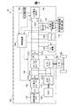
図1は本発明の一実施形態としての外部給電システム100を備える燃料電池車両10の構成を示す概略図である。燃料電池車両10は、燃料電池(Fuel Cell、「FC」とも略す)110と、二次電池(「BAT」とも略す)140とを備え、それらが出力する電力を駆動力として走行する。また、本実施形態の燃料電池車両10は、外部給電システム100としても機能し、その停車中に、外部負荷(不図示)に対して電力を供給することができる。燃料電池車両10は、具体的に、以下のような構成を有している。
FIG. 1 is a schematic diagram showing a configuration of a
なお、本明細書における「燃料電池車両10の停車中」とは、燃料電池110および二次電池140から後述するモーター136の駆動に対して電力を供給していない状態を意味する。そして、アクセル操作やシフトチェンジによって加速が開始される状態である、いわゆるアイドリング状態を含まないものとする。なお、パーキングブレーキ(いわゆる、サイドブレーキ)などの制動機構によって、燃料電池車両10の移動が固定的に制限された状態も、この状態に含まれるものとする。一方、「燃料電池車両10の走行時」とは、燃料電池110と二次電池140の少なくとも一方の電力を利用して、モーター136を駆動させている状態を意味する。そして、この状態には、上記のアイドリング状態(パーキングブレーキなどの制動機構によって固定的に移動が制限された状態を除く)が含まれるものとする。
In the present specification, “when the
燃料電池110は、反応ガスとして水素と空気(具体的には、酸素)の供給を受けて発電する固体高分子形燃料電池である。二次電池140は、例えばリチウムイオン電池で構成することができる。なお、燃料電池110や二次電池140としては、固体高分子形燃料電池やリチウムイオン電池に限らず、他の種々のタイプの燃料電池や充放電可能な電池を採用することができる。
The
燃料電池車両10は、さらに、FC昇圧コンバーター120と、パワーコントロールユニット(「PCU」とも略す)130と、モーター136と、エアーコンプレッサー(「ACP」とも略す)138と、SOC検出部142と、FC補機150と、空調装置(「エアコン」とも略す)160と、外部給電部170と、電流センサー(「DCS」とも略す)172と、制御装置180と、車輪WLと、を備える。
The
なお、燃料電池車両10は、燃料電池110の発電のための設備として反応ガスの供給部や排出部、冷媒供給部などを搭載し、車両としての種々の機器等を搭載しているが、それらの図示及び説明は省略する。但し、反応ガスの供給部に含まれる燃料ポンプやエアーコンプレッサー、及び、冷媒供給部に含まれる冷媒ポンプ等の機器(「補機」とも呼ばれる)は、燃料電池110や二次電池140の電力の一部を利用して駆動される機器であり、後述する外部給電制御に関係する。そこで、後述する低圧直流配線DCLからの電力で動作する燃料ガス用の燃料ポンプや冷媒用の冷媒ポンプは一つにまとめてFC補機150として図示し、後述する高圧直流配線DCHからの電力で動作する酸化ガス用のエアーコンプレッサー(ACP)138については、独立して図示した。
The
制御装置180は、CPUやROM、RAM等を備えるマイクロコンピューターによって構成されている。制御装置180は、運転者による運転モード切替スイッチ(不図示)を介した切り替え操作を受け付け、燃料電池車両10の運転モードを切り替える。ここで、本実施形態の燃料電池車両10は、運転モードとして、「通常走行モード」と、「電力給電モード」とを有している。
The
「通常運転モード」とは、燃料電池車両10を運転者の操作に基づき走行させるためのモードである。通常運転モードが選択されているときには、制御装置180は、運転者によるアクセル操作などの操作を受け付け、その操作内容に応じて、燃料電池110の発電や二次電池140の充放電を制御する。一方、「電力給電モード」とは、燃料電池車両10が停止した状態で、燃料電池車両10を、外部負荷に電力を供給させる外部給電システム100として機能させるモードである。なお、電力給電モードにおける具体的な制御内容については後述する。
The “normal operation mode” is a mode for causing the
燃料電池110は、FC昇圧コンバーター120を介して高圧直流配線DCHに接続され、高圧直流配線DCHを介してPCU130に含まれるモータードライバー132及びACPドライバー137に接続されている。また、二次電池140は、低圧直流配線DCLを介してPCU130に含まれるDC/DCコンバーター134に接続され、DC/DCコンバーター134が高圧直流配線DCHに接続されている。
The
FC昇圧コンバーター120は、燃料電池110の出力電圧VFCをモータードライバー132及びACPドライバー137で利用可能な高圧電圧VHに昇圧する。
The
モータードライバー132は、ギア等を介して車輪WLを駆動するモーター136に接続されている。モーター136は、三相コイルを備える同期モーターによって構成されている。モータードライバー132は、三相インバーター回路によって構成され、FC昇圧コンバーター120を介して供給される燃料電池110の出力電力およびDC/DCコンバーター134を介して供給される二次電池140の出力電力を三相交流電力に変換してモーター136に供給する。
The
ACPドライバー137は、ACP138に接続されている。ACP138は、駆動モーター136と同様に、三相コイルを備える同期モーターによって駆動される。ACPドライバー137は、モータードライバー132と同様に、三相インバーター回路によって構成され、FC昇圧コンバーター120を介して供給される燃料電池110の出力電力およびDC/DCコンバーター134を介して供給される二次電池140の出力電力を三相交流電力に変換してACP138に供給する。ACP138は、供給された電力に応じた駆動されたモーターの回転に応じて燃料電池110に空気(エアー)を供給する。
The
制御装置180は、通常走行モードのときには、モータードライバー132と、DC/DCコンバーター134とにそれぞれ、アクセル開度に応じた駆動信号を生成して送信する。モータードライバー132は、制御装置180の駆動信号に応じて、交流電圧のパルス幅を調整するなどして、モーター136にアクセル開度に応じた回転駆動をさせる。これにより、燃料電池車両10の走行が行われる。
In the normal travel mode,
DC/DCコンバーター134は、制御装置180からの駆動信号に応じて高圧直流配線DCHの電圧レベルを可変に調整し、二次電池140の充電/放電の状態を切り替える。DC/DCコンバーター134は、二次電池140が放電状態の場合には、二次電池の出力電圧VBATをモータードライバー132で利用可能な高圧電圧VHに変換し、二次電池140が充電状態の場合には、FC昇圧コンバーター120から出力される高圧電圧VHを二次電池140に充電可能な低圧電圧VLに変換する。なお、モーター136において回生電力が発生する場合には、その回生電力は、モータードライバー132によって直流電力に変換され、DC/DCコンバーター134を介して二次電池140に充電される。
The DC /
SOC検出部142は、二次電池140の充電状態(SOC)を検出し、制御装置180に送信する。なお、本明細書において「充電状態(SOC)」とは、二次電池140の満充電容量に対する現在の充電残量(蓄電量)の比率を意味する。SOC検出部142は、二次電池140の温度や、出力電圧、出力電流を検出し、それらの検出値に基づき、SOCを検出する。なお、SOC検出部142は本発明の「蓄電量検出部」に相当する。
The
制御装置180は、SOC検出部142が検出したSOCを取得し、取得したSOCに基づき、二次電池140のSOCが所定の範囲内に収まるように、二次電池140の充放電を制御する。以後、本明細書では、この制御装置180によるSOCの検出値に基づく二次電池140の充放電制御を「SOC制御」とも呼ぶ。制御装置180は、SOC制御を開始する際に、二次電池140のSOCの許容範囲を規定するための基準となるSOC目標値を予め設定する。なお、通常運転モードにおけるSOC制御については従来と同様であり、電力給電モードにおけるSOC制御に後述する特徴を有している。
The
FC補機150とエアコン160と外部給電部170は、それぞれ、低圧直流配線DCLに接続されている。FC補機150は、上述したように、燃料ポンプや冷媒ポンプ等の燃料電池110の発電のための補機類であり、燃料電池110や二次電池140から電力の一部が供給されて駆動される。エアコン160は、燃料電池車両10の空調機器であり、同様に、燃料電池110や二次電池140から電力の一部が供給されて駆動される。外部給電部170は、以下で説明するように、外部負荷へ電力を供給するための給電機器であり、同様に、燃料電池110や二次電池140から電力の一部が供給されて駆動される。
The FC
外部給電部170には、交流電力によって作動する外部負荷を接続させるための外部給電装置174が接続可能である。外部給電部170に外部給電装置174が接続されることによって、燃料電池車両10は、外部給電システム100として機能し、燃料電池110及び二次電池140から、外部給電装置174に接続された外部負荷(不図示)に電力を供給することを可能としている。なお、本実施形態の外部給電部170は、低圧直流配線DCLからの直流電力を外部給電装置174に供給する構成であり、外部給電装置174は、外部給電部170から供給される直流電力を交流100Vの交流電力に変換し、商用電源用のコンセントに接続された外部負荷へ電力を供給する構成である。
An external
外部給電部170と低圧直流配線DCLとを接続する配線には電流センサー172が設けられており、電流センサー172によって外部給電部170に供給される電流量が計測される。
A
制御装置180は、電流センサー172が計測した電流値(計測値)を取得し、取得した電流値に基づいて、外部給電部170及び外部給電装置174を介して外部負荷に供給される電力量を求めることができる。従って、電流センサー172は、外部給電部170及び外部給電装置174を介して外部負荷に供給される電力量を計測するセンサーに相当する。すなわち、電流センサー172は、本発明の外部に給電される電力を計測するセンサーに相当する。
The
なお、制御装置180は、外部給電部170を介して外部給電装置174に対して供給可能な電力(「給電許可電力」とも呼ぶ)の上限値を設定することができる。外部給電装置174は、接続された外部負荷への電力供給を設定された上限値以下に制限することができる。
Note that the
上述した燃料電池車両10の構成では、燃料電池110は、二次電池140及び外部給電部170が接続された低圧直流配線DCLに対して、FC昇圧コンバーター120、高圧直流配線DCH及びDC/DCコンバーター134を介して接続されている。しかしながら、これに限定されるものではなく、燃料電池110の出力端(燃料電池の内部を含む)からDC/DCコンバーター134の出力端(DC/DCコンバータの外部を含む)までの間に設けられたスイッチによって、低圧直流配線DCLに対する燃料電池110の接続および切り離しを可能としてもよい。また、二次電池140の出力端(二次電池の内部を含む)に設けられたスイッチによって低圧直流配線DCLに対する二次電池140の接続および切り離しを可能としてもよい。なお、低圧直流配線DCLが本発明の「電力配線」に相当する。
In the configuration of the
通常運転モードにおける燃料電池車両10の制御動作は、公知の燃料電池車両と同様であるので説明を省略し、以下では、電力給電モードにおける外部給電システム100の制御動作について説明する。
Since the control operation of the
図2は、制御装置180によって電力給電モードで実行される外部給電システム100の制御手順を示すフローチャートである。制御装置180は、まず、ステップS20において、電流センサー172が正常な場合の外部給電(「正常時外部給電」とも呼ぶ)を開始する。なお、正常時外部給電の動作については、後述する。そして、ステップS30において、電流センサー172の信頼性の有無を判定する。電流センサー172に、断線故障や地絡故障、オフセット故障等の故障による異常が発生している場合には、電流センサー172が示す値(「計測値」あるいは「電流センサー値」とも呼ぶ)が、故障状態に応じた異常値を示す。そこで、これらの異常状態の有無に基づいて電流センサー172の信頼性の有無を判定することができ、電流センサーの異常を検知することが可能である。
FIG. 2 is a flowchart showing a control procedure of the external
電流センサー172の信頼性有り(電流センサー172が正常)と判定された場合には、制御装置180は、電力給電モードの動作を終了するまで、ステップS30における電流センサー172の信頼性判定を繰り返すとともに、並行して、ステップS20で開始した正常時外部給電の動作を継続する。これに対して、電流センサー172の信頼性無し(電流センサー172が異常)と判定された場合には、制御装置180は、ステップS50において正常時外部給電の制御を終了し、ステップS60において、電流センサー172が異常な場合の外部給電(「異常時外部給電」とも呼ぶ)を開始する。なお、異常時外部給電の動作については、後述する。そして、ステップS60で開始した異常時外部給電の動作は、電力給電モードの動作を終了するまで継続される(ステップS170)。
When it is determined that the
なお、図2のステップS20の前に、ステップS30と同様に、電流センサー172の信頼性の有無を判定し、電流センサー172の信頼性有りの場合にはステップS20の正常時外部給電を開始し、電流センサー172の信頼性無しの場合にはステップS60の異常時外部給電を開始するようにしてもよい。
Before step S20 in FIG. 2, as in step S30, it is determined whether or not the
図3は、正常時外部給電の制御手順を示すフローチャートである。ステップS210において、制御装置180は、燃料電池110の発電出力(「発電電力」あるいは「発電量」とも呼ぶ)Pfcのうち、外部負荷の動作に要する電力(以下「外部要求電力Porq」とも呼ぶ)に相当する外部給電分Poを、電流センサー172の示す値(電流センサー値Idsc)に基づいて設定する。外部要求電力Porqは、低圧直流配線DCLによって外部給電部170に供給される電流量(電流センサー値Idsc)及び低圧電圧VLの積から求められる。ステップS220において、制御装置180は、ACP138およびFC補機150の動作に要する電力(以下「補機要求電力Pcrq」とも呼ぶ)に相当する補機消費分Pc、および、エアコン160の動作に要する電力(以下「空調要求電力Parq」とも呼ぶ)に相当する空調消費分Paを設定する。なお、補機要求電力PcrqはACP138の動作状態およびFC補機150の動作状態から求められ、空調要求電力Parqはエアコン160の動作状態から求められる。ステップS230において、制御装置180は、二次電池のSOC補正分Psを設定する。SOC補正分Psは、SOCの現在値が目標値よりも低いときに、目標値に戻すように2次電池を充電するのに必要な発電量である。このSOC補正分Psの設定は、後述する異常時外部給電におけるSOC補正分Psの設定においても同様であるので、その詳細については、後述する異常時外部給電において説明する。なお、ACP138とFC補機150とエアコン160は、外部給電モードにおいて動作する外部給電システム100からの給電によって動作する燃料電池車両10内の機器であるので、補機消費分Pcおよび空調消費分Paを「車両内機器消費分」とも呼ぶ。なお、本実施形態では、ACP138とFC補機150とエアコン160を車両内機器としたが、これに限定されるものではなく、エアコン160を省略してもよい。また、他の機器を車両内機器として備え、その消費分を車両内機器消費分としてもよい。
FIG. 3 is a flowchart showing a control procedure of normal external power feeding. In step S210, the
次に、制御装置180は、ステップS240において、外部給電分Poと補機消費分Pcと空調消費分PaとSOC補正分Psとを合算して、燃料電池110に要求される発電出力要求値を算出し、発電出力Pfcとして設定する。そして、制御装置180は、ステップS250において、燃料電池110の発電条件(反応ガスの供給条件、冷却条件等)を制御して、設定した発電出力Pfcに相当する電力が出力可能となるように燃料電池110の発電を制御する。
Next, in step S240, the
なお、上述した正常時外部給電制御におけるステップS210〜ステップS250による燃料電池110の制御動作は、上述した電流センサー172の異常判定時における終了指示(図2のステップS50)、及び、電力給電モードの終了指示があるまで繰り返し実行される(ステップS260)。
Note that the control operation of the
以上説明したように、電流センサー172が正常な場合における正常時外部給電において、基本的には、二次電池140のSOCはSOC目標値を維持し、二次電池140に蓄電されている電気を消費することはなく、必要な電力は燃料電池110の発電によって賄われる。但し、SOCがSOC目標値よりも高い場合には、二次電池140に蓄電されている電気が消費されてもよい。
As described above, in normal external power feeding when the
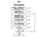
図4は、異常時外部給電の制御手順を示すフローチャートである。ステップS410において、制御装置180は、電流センサー値を無効(Idsc=0)として、燃料電池110の発電出力(発電量)Pfcのうち、外部給電分Poを0kWに設定する。この場合、上述した正常時外部給電において二次電池140のSOCがSOC目標値を維持することによってSOC補正分Psも0kWとなっているので、燃料電池110の発電出力Pfcは、補機消費分Pcと空調消費分Pa(車両内機器消費分)に対応する電力のみとなる。このため、外部給電分Poに対応する電力は、二次電池140から賄われることになる。
FIG. 4 is a flowchart showing a control procedure of external power supply during an abnormality. In step S410, the
ステップS420において、制御装置180は、外部への給電に許容できる電力(給電許可電力)Palに上限値Pulを設定し、上限ガードをかける。この上限値Pulは、外部給電部170を介して外部給電装置174に設定され、外部給電装置174から外部負荷への電力の供給が上限値Pul以下に制限される。これにより、二次電池140のSOCが、後述する二次電池140からの外部への給電によって二次電池140のSOCの許容範囲の下限値よりも下回らないように制限することができる。なお、この給電許可電力Palの上限値Pulは、SOC補正分Psの設定可能な最大値に安全係数を乗じた値に、温度条件等に依存して変化する二次電池の充電容量(電力)に関する制限や放電容量(電力)に関する制限を考慮して決定される。正常時外部給電における給電許可電力Palは、例えば10kW以下に制限される。これに対して、異常時外部給電における給電許可電力Palの上限値Pulは、例えば、3kW〜6kW程度に制限される。
In step S420, the
ステップS430において、制御装置180は、ACP138とFC補機150の補機要求電力Pcrqに相当する補機消費分Pc、及び、エアコン160の空調要求電力Parqに相当する空調消費分Paを設定する。なお、補機要求電力Pcrqは図3のステップS220と同様にACP138及びFC補機150の動作状態から求められ、空調要求電力Parqは図3のステップS220と同様にエアコン160の動作状態から求められる。
In step S430, the
そして、ステップS440において、制御装置180は、SOC検出部142によって現在のSOC値SOC(i)を取得し、取得したSOC値SOC(i)に対応する補正分Ps(i)を、予め用意したSOC補正マップに基づいて次式に示すように取得する。
Ps(i)=Pc(SOC(i)) …(1)
ここで、Pc(SOC)は、SOCとSOC補正分Psとの関係を示すSOC補正マップの特性を関数の表現形式で示したものであり、Pc(SOC(i))は、取得した現在のSOC値SOC(i)に対応するSOC補正分Ps(i)としてSOC補正マップから導き出した値を示している。
In step S440,
Ps (i) = Pc (SOC (i)) (1)
Here, Pc (SOC) indicates the characteristic of the SOC correction map indicating the relationship between the SOC and the SOC correction amount Ps in a function expression form, and Pc (SOC (i)) is the acquired current A value derived from the SOC correction map is shown as the SOC correction amount Ps (i) corresponding to the SOC value SOC (i).
図5は、SOCとSOC補正分との関係を表すSOC補正マップの例を示す説明図である。SOC補正マップの特性Pc(SOC)は、SOC目標値Tsoc(本例では60%)より上側のSOCでは、SOCが大きくなるほどSOC補正分Psが放電側に大きくなるように設定されている。また、SOC目標値Tsocより下側のSOCでは、SOC目標値Tsocから低下閾値Dth(本例では58%)までの範囲のSOC補正分Psは0に設定され、低下閾値Dthよりも下側の範囲のSOC補正分Psは、SOCが小さくなるほど充電側に大きくなるように設定されている。なお、SOC目標値Tsocは、二次電池140の使用可能な許容範囲内において、充放電の発生状態を考慮した任意の値に設定可能である。
FIG. 5 is an explanatory diagram showing an example of an SOC correction map representing the relationship between the SOC and the SOC correction amount. The SOC correction map characteristic Pc (SOC) is set so that the SOC correction amount Ps increases toward the discharge side as the SOC increases in the SOC above the SOC target value Tsoc (60% in this example). Further, in the SOC lower than the SOC target value Tsoc, the SOC correction amount Ps in the range from the SOC target value Tsoc to the decrease threshold Dth (58% in this example) is set to 0, and is lower than the decrease threshold Dth. The SOC correction amount Ps in the range is set so as to increase toward the charging side as the SOC decreases. The SOC target value Tsoc can be set to an arbitrary value in consideration of the state of occurrence of charging / discharging within the allowable range where the
SOC目標値Tsocから低下閾値DthまでのSOC補正分Psが0に設定されているのは、別に独立して実行される二次電池の充電制御によって回復可能なSOCの範囲であるので、本例の制御においては、この範囲でのSOC補正分の設定を0とすることにより、燃料電池の発電による無駄な燃料消費を抑制するためである。従って、この点について考慮しなければ、必ずしも、このような不感領域(SOC目標値Tsocから低下閾値Dthまでの範囲)を設ける必要はなく、単純に、SOC目標値Tsocより下側のSOCでは、SOCが小さくなるほどSOC補正分Psが充電側に大きくなるように設定されていてもよい。 The SOC correction amount Ps from the SOC target value Tsoc to the decrease threshold value Dth is set to 0 because this is the range of SOC that can be recovered by charge control of the secondary battery that is separately executed. In this control, by setting the SOC correction amount in this range to 0, wasteful fuel consumption due to power generation by the fuel cell is suppressed. Therefore, if this point is not taken into consideration, it is not always necessary to provide such a dead region (a range from the SOC target value Tsoc to the decrease threshold Dth). Simply, in the SOC below the SOC target value Tsoc, The SOC correction amount Ps may be set to increase toward the charging side as the SOC decreases.
例えば、取得したSOC値SOC(i)がSOC目標値Tsocから低下閾値Dthまでの範囲内であった場合には、図5のSOC補正マップに基づいて、SOC値SOC(i)に係らず、一定のPs(SOC(i))、すなわち、「0」が、SOC補正分Ps(i)として取得される。 For example, when the obtained SOC value SOC (i) is within the range from the SOC target value Tsoc to the decrease threshold Dth, regardless of the SOC value SOC (i) based on the SOC correction map of FIG. Constant Ps (SOC (i)), that is, “0” is acquired as the SOC correction amount Ps (i).
また、給電によりSOCが低下して、取得したSOC値SOC(i)が低下閾値Dthよりも下側である場合には、図5のSOC補正マップに基づいて、SOC目標値Tsocからの差に応じて充電側に大きくなった正の値のPs(SOC(i))が、SOC補正分Ps(i)として取得される。ここで、図5に示すように、取得したSOC値SOC(i)が、一つ前のサイクルで取得したSOC値SOC(i−1)よりも下側である場合、SOC目標値Tsocからの差の大きさに応じて、一つ前の値Ps(SOC(i−1))よりもさらに大きい正の値のPs(SOC(i))が、SOC補正分Ps(i)として取得される。これは、SOCの低下を検知することに相当する。この場合には、前のサイクルにおけるSOC補正分よりもさらに充電方向の正のSOC補正分が増加されることになる。また、図5に示すように、取得したSOC値SOC(i)が、低下閾値Dthよりも下側であるが、一つ前のサイクルで取得したSOC値SOC(i−1)よりも上側である場合、SOC目標値Tsocからの差の大きさに応じて充電側ではあるが、一つ前の値Ps(SOC(i−1))よりも小さい正の値のPs(SOC(i))が、SOC補正分Ps(i)として取得される。これは、SOCの上昇を検知することに相当する。この場合には、充電方向の正のSOC補正分ではあるが、前のサイクルにおけるSOC補正分よりも減少されたSOC補正分とされる。 Further, when the SOC decreases due to power supply and the acquired SOC value SOC (i) is below the decrease threshold Dth, the difference from the SOC target value Tsoc is calculated based on the SOC correction map of FIG. Accordingly, a positive value Ps (SOC (i)) that increases in response to the charging side is acquired as the SOC correction amount Ps (i). Here, as shown in FIG. 5, when the acquired SOC value SOC (i) is lower than the SOC value SOC (i−1) acquired in the previous cycle, from the SOC target value Tsoc. A positive value Ps (SOC (i)) larger than the previous value Ps (SOC (i-1)) is acquired as the SOC correction amount Ps (i) according to the magnitude of the difference. . This corresponds to detecting a decrease in SOC. In this case, the positive SOC correction amount in the charging direction is further increased than the SOC correction amount in the previous cycle. Further, as shown in FIG. 5, the acquired SOC value SOC (i) is lower than the decrease threshold Dth, but is higher than the SOC value SOC (i−1) acquired in the previous cycle. In some cases, a positive value Ps (SOC (i)) smaller than the previous value Ps (SOC (i-1)) is on the charging side depending on the magnitude of the difference from the SOC target value Tsoc. Is obtained as the SOC correction amount Ps (i). This corresponds to detecting an increase in SOC. In this case, although it is a positive SOC correction amount in the charging direction, it is an SOC correction amount that is reduced from the SOC correction amount in the previous cycle.
SOCの低下の場合と同様に、取得したSOC値SOC(i)がSOC目標値Tsocよりも上側であった場合には、図5のSOC補正マップに基づいて、SOC目標値Tsocからの差の大きさに応じて放電側に大きくなった負の値のPs(SOC(i))が、SOC補正分Ps(i)として取得される。そして、前のサイクルにおけるSOC値SOC(i−1)との大小関係によるSOCの上昇低下に応じて放電方向の負のSOC補正分が増減される。 As in the case of the decrease in the SOC, when the obtained SOC value SOC (i) is above the SOC target value Tsoc, the difference from the SOC target value Tsoc is calculated based on the SOC correction map in FIG. A negative value Ps (SOC (i)) that increases on the discharge side in accordance with the magnitude is acquired as the SOC correction amount Ps (i). Then, the negative SOC correction amount in the discharge direction is increased / decreased according to the increase / decrease in the SOC due to the magnitude relationship with the SOC value SOC (i−1) in the previous cycle.
次に、制御装置180は、ステップS450において、補機消費分Pcと空調消費分PaとSOC補正分Psとを合算して、燃料電池110に要求される発電出力要求値を算出し、発電出力Pfcとして設定する。そして、制御装置180は、ステップS460において、燃料電池110の発電条件(反応ガスの供給条件、冷却条件等)を制御して、設定した発電出力Pfcに相当する電力が出力可能となるように燃料電池110の発電量を制御する。
Next, in step S450, the
なお、上述した異常時外部給電制御におけるステップS430〜ステップS460による燃料電池110の制御動作は、上述した電力給電モードの終了指示があるまで繰り返し実行される(ステップS470)。
It should be noted that the control operation of
以上説明した異常時外部給電の制御動作では、SOCが低下した場合にはSOCの低下を止めるようにSOC補正分Psが充電方向に増加するように設定され、この増加分に応じた電力が燃料電池110で発電されて出力される。そして、この動作を繰り返し実行することにより、外部給電される電力分と釣り合いが取れてSOCの低下を止めることが可能なSOC補正分Psが設定され、これに応じた燃料電池110での発電が可能となる。これにより、電流センサー172に異常があった場合においても、外部給電を継続することが可能となる。そして、この釣り合いが取れた状態において、SOCが上昇した場合にはSOCの上昇を止めるようにSOC補正分Psが減少設定され、この減少分に応じた電力の燃料電池110での発電が減少される。そして、この動作を繰り返し実行することにより、外部給電される電力分と釣り合いが取れてSOCの上昇を止めることが可能なSOC補正分Psが設定され、これに応じた燃料電池110での発電が可能となる。
In the control operation of the external power supply at the time of abnormality described above, when the SOC decreases, the SOC correction amount Ps is set to increase in the charging direction so as to stop the decrease of the SOC, and the electric power corresponding to the increase amount is supplied to the fuel. The
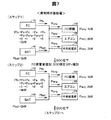
以下では、具体例に則して異常時外部給電の制御動作について説明する。図6は異常時外部給電の開始前に実行されていた正常時外部給電の状態の具体例を示す説明図である。図7及び図8は、図6に示した正常時外部給電の状態から開始された異常時外部給電の状態の具体例を示す説明図である。 Hereinafter, the control operation of the external power supply at the time of abnormality will be described according to a specific example. FIG. 6 is an explanatory diagram showing a specific example of a state of normal external power feeding that was executed before the start of abnormal external power feeding. FIGS. 7 and 8 are explanatory diagrams illustrating a specific example of the state of external power supply in an abnormal state started from the state of external power supply in a normal state illustrated in FIG. 6.
図6に示すように、異常時外部給電の開始直前の正常時外部給電において、ACP138及びFC補機150の補機要求電力Pcrq:1kw、エアコン160の空調要求電力Parq:2kW、及び、外部給電部170の外部要求電力Porq:3kWに対応して、補機消費分Pc:1kW、空調消費分Pa:2kW、及び、外部給電分Po:3kWの合計6kWが燃料電池110の発電出力Pfcとして燃料電池110から出力されている。この場合、二次電池140の蓄電量は消費されず、SOCはSOC目標値Tsocの状態が維持されている。
As shown in FIG. 6, in normal external power supply immediately before the start of abnormal external power supply, the auxiliary power requirement Pcrq of the
そして、図6に示した状態での動作中に、電流センサー172に異常が発生した場合には、まず、図7のステップ1に示したように、燃料電池110の発電出力Pfcのうち外部給電分Poが0kWとされるので(図4のステップS410参照)、燃料電池110の発電出力Pfcは3kWとなる。このため、不足する外部要求電力Porq:3kW分の電力は、二次電池140の出力Pbat:3kWによって賄われる。この結果、二次電池140の蓄電量が消費されてSOCが低下することになる。
When an abnormality occurs in the
SOCが低下すると、SOC補正分Psが増加され(図4のステップS440,図5参照)、SOCの低下が検知されることとなり、SOCの低下を止めるように燃料電池110の発電出力Pfcが増加される(図4のステップS450,S460参照)。例えば、図7のステップ2に示したように、SOC補正分Psがステップ1の0kWから1kWと増加されて、合計4kWの燃料電池110の発電出力Pfcが出力される。しかしながら、外部要求電力Porq:3kWのうち1kWは燃料電池110の発電出力Pfcで賄えることとなったが、まだ2kW分の電力が不足することになる。このため、不足する2kW分の電力は、二次電池140の出力Pbat:2kWによって賄われる。従って、この場合においても、二次電池140の蓄電量の消費は止まらず、まだSOCは低下することになる。
When the SOC decreases, the SOC correction amount Ps is increased (see step S440 in FIG. 4 and FIG. 5), and the decrease in the SOC is detected, and the power generation output Pfc of the
まだSOCが低下する場合には、さらにSOCの補正分Psが増加され、SOCの低下を止めるように燃料電池110の発電出力Pfcが増加される。例えば、図8のステップ3に示したように、SOC補正分Psがステップ2の1kWから2kWと増加されて、合計5kWの燃料電池110の発電出力Pfcが出力される。しかしながら、外部要求電力Porq:3kWのうち2kWは燃料電池110の発電出力Pfcで賄えることとなったが、まだ1kW分の電力が不足することになる。このため、不足する1kW分の電力は、二次電池140の出力Pbat:1kWによって賄われる。従って、この場合においても、二次電池140の蓄電量の消費は止まらず、SOCはさらに低下することになる。
If the SOC still decreases, the SOC correction amount Ps is further increased, and the power generation output Pfc of the
さらにまだSOCが低下する場合には、さらにSOCの補正分Psが増加され、SOCの低下を止めるように燃料電池110の発電出力Pfcが増加される。例えば、図8のステップ4に示したように、SOC補正分Psがステップ3の2kWから3kWと増加されて、合計6kWの燃料電池110の発電出力Pfcが出力される。この結果、外部要求電力Porq:3kWは全て燃料電池110の発電出力Pfcで賄えることとなり、燃料電池110の発電出力と、ACP138とFC補機150とエアコン160と外部給電部170での電力消費量が釣り合った状態となる。これにより、二次電池140からの出力Pbatは0kWとなって、二次電池140の蓄電量の消費が止まり、SOCを一定状態とすることができる。
Further, when the SOC still decreases, the SOC correction amount Ps is further increased, and the power generation output Pfc of the
以降、外部要求電力Porqが変化しない限り、図8のステップ4の状態が維持されて燃料電池110の発電出力が継続されることにより、二次電池140の電力を消費せずに、外部給電を継続することができる。そして、この状態で外部要求電力Porqが変化し、SOCが低下した場合には、SOC補正分Psが増加されて、燃料電池110の発電出力Pfcが増加され、SOCの低下が止まってSOCが一定となるように制御される。反対に、SOCが上昇した場合には、SOC補正分Psが減少されて、燃料電池110の発電出力Pfcが減少され、SOCの上昇が止まってSOCが一定となるように制御される。
Thereafter, as long as the external required power Porq does not change, the state of step 4 in FIG. 8 is maintained, and the power generation output of the
以上説明した異常時外部給電では、外部給電に要する電力を計測するための電流センサー172に異常が発生していても、一旦、二次電池140でその電力を賄いつつ、二次電池140のSOCの変動を止めるように燃料電池110の発電出力(発電量)を制御することができる。これにより、二次電池140の充放電の発生を抑制するとともに、二次電池140のSOCが許容範囲内を維持しつつ、外部給電に要する電力を燃料電池110からの発電出力で賄うように制御して、外部給電を継続して実行することが可能である。従って、使用者の使い勝手を向上させることができる。また、二次電池140の充放電の発生が抑制されるので、二次電池の劣化を抑制することが可能であり、二次電池の寿命を向上させることが可能である。
In the abnormal external power supply described above, even if an abnormality has occurred in the
なお、異常時外部給電を開始して、外部給電分Poを0kWと設定した後、二次電池140のSOCが一定に戻った際のSOC補正分Psの値は、外部要求電力Porqに対応する。また、さらにその後、SOCが変化してからSOCが一定となるまでに変化させたSOC補正分Psの変化分の値は、外部要求電力Porqの変化分に対応する。従って、電流センサー172の代わりに、SOC補正分Psの値を用いて、外部給電に要する電力を計測することが可能である。これにより、例えば、SOC補正分Psにより計測した外部給電分に要する電力を燃料電池110の外部給電分Poとして設定して、設定後のSOC補正分Psをリセットするようにしてもよい。
Note that the value of the SOC correction amount Ps when the SOC of the
上記実施形態では、外部給電部170は、低圧直流配線DCLからの直流電力を外部給電装置174に供給し、外部給電装置174は、外部給電部170から供給される直流電力を交流100Vの交流電力に変換し、商用電源用のコンセントに接続された外部負荷へ電力を供給する構成とした。しかし、これに限定されるものではなく、外部給電部170で直流電力を交流100V等の交流電力に変換し、外部給電装置174に供給する構成としてもよい。また、外部給電装置174は、商用電源用のコンセントによって外部負荷と接続しなくとも良い。
In the above embodiment, the external
上記実施形態において、燃料電池車両10は、運転モード切替スイッチによって、通常走行モードと電力給電モードとを切り替えていた。しかし、運転モード切替スイッチは省略されるものとしても良い。この場合には、制御装置180が、燃料電池車両10の運転状態や外部負荷の接続状態に基づいて、通常走行モードと電力給電モードとを切り替えるものとしても良い。例えば、制御装置180は、燃料電池車両10のアイドリング時に、外部負荷が接続されたとき、または、外部負荷による電力使用が開始されたとき、パーキングブレーキがかけられたときに、自動的に電力給電モードに移行するものとしても良い。また、制御装置180は、電力給電モードのときに、パーキングブレーキが解除されたり、アクセルペダルが踏み込まれた場合に、外部負荷の電気的接続を遮断し、通常走行モードに強制的に移行するものとしても良い。
In the above embodiment, the
本発明は、上述の実施形態や実施例、変形例に限られるものではなく、その趣旨を逸脱しない範囲において種々の構成で実現することができる。例えば、発明の概要の欄に記載した各形態中の技術的特徴に対応する実施形態、実施例、変形例中の技術的特徴は、上述の課題の一部または全部を解決するために、あるいは、上述の効果の一部または全部を達成するために、適宜、差し替えや組み合わせを行うことが可能である。また、その技術的特徴が本明細書中に必須なものとして説明されていなければ、適宜、削除することが可能である。 The present invention is not limited to the above-described embodiments, examples, and modifications, and can be realized with various configurations without departing from the spirit thereof. For example, the technical features in the embodiments, examples, and modifications corresponding to the technical features in each embodiment described in the summary section of the invention are to solve some or all of the above-described problems, or In order to achieve part or all of the above-described effects, replacement or combination can be performed as appropriate. Further, if the technical feature is not described as essential in the present specification, it can be deleted as appropriate.
10…燃料電池車両
100…外部給電システム100
110…燃料電池(FC)
120…FC昇圧コンバーター
130…パワーコントロールユニット(PCU)
132…モータードライバー
134…DC/DCコンバーター
136…モーター
137…ACPドライバー
138…エアーコンプレッサー(ACP)
140…二次電池(BAT)
142…SOC検出部
150…FC補機
160…空調装置(エアコン)
170…外部給電部
172…電流センサー(DCS)
174…外部給電装置
180…制御装置
DCL…低圧直流配線
DCH…高圧直流配線
WL…車輪
DESCRIPTION OF
110 ... Fuel cell (FC)
120 ...
132 ...
140 ... Secondary battery (BAT)
142 ...
170: External
174 ... External
Claims (5)
前記燃料電池と前記二次電池とが接続可能な電力配線から外部に給電される電力を計測するセンサーの異常を検知した場合において、
(a)前記二次電池の蓄電量の減少が検知される場合には、前記蓄電量の減少を止めるように前記燃料電池の発電量を増加させて外部給電を行い、
(b)前記蓄電量の増加が検知される場合には、前記蓄電量の増加を止めるように前記燃料電池の発電量を減少させて外部給電を行う
ことを特徴とする外部給電システムの制御方法。 A control method by a control device of an external power supply system that supplies power from a fuel cell and a secondary battery mounted on a vehicle to the outside,
In the case of detecting an abnormality of a sensor that measures power supplied to the outside from a power wiring that can connect the fuel cell and the secondary battery,
(A) When a decrease in the storage amount of the secondary battery is detected, external power feeding is performed by increasing the power generation amount of the fuel cell so as to stop the decrease in the storage amount,
(B) When an increase in the amount of stored electricity is detected, external power feeding is performed by reducing the amount of power generated by the fuel cell so as to stop the increase in the amount of stored electricity. .
前記センサーの異常を検知した場合には、前記燃料電池の発電量のうち、前記センサーが示す値から求められる前記外部への給電のための発電量分をゼロとした上で、前記(a)または前記(b)を実行することを特徴とする外部給電システムの制御方法。 It is a control method of the external electric power feeding system according to claim 1,
When an abnormality of the sensor is detected, out of the power generation amount of the fuel cell, the power generation amount for power feeding to the outside obtained from the value indicated by the sensor is set to zero, and then (a) Or the said (b) is performed, The control method of the external electric power feeding system characterized by the above-mentioned.
前記燃料電池の発電量は、前記外部への給電のための発電量分と、前記車両内の機器で消費される車両内機器消費分と、前記蓄電量の増減に応じた補正分と、の合計として設定されることを特徴とする外部給電システムの制御方法。 A method for controlling an external power feeding system according to claim 1 or 2,
The power generation amount of the fuel cell includes a power generation amount for power supply to the outside, a vehicle device consumption amount consumed by the device in the vehicle, and a correction amount according to the increase or decrease of the power storage amount. A control method for an external power supply system, wherein the control method is set as a total.
前記センサーの異常を検知した場合における前記外部への給電電力は、前記センサーが正常である場合に許容される値未満に制限されることを特徴とする外部給電システムの制御方法。 It is the control method of the external electric power feeding system as described in any one of Claim 1- Claim 3, Comprising:
The control method of the external power supply system, wherein the power supply to the outside when the abnormality of the sensor is detected is limited to a value that is allowed when the sensor is normal .
前記燃料電池と前記二次電池とが接続可能な電力配線から外部に給電するめの外部給電部と、
前記外部給電部を介して前記外部に給電される電力を計測するセンサーと、
前記二次電池の蓄電量を示す値を検出する蓄電量検出部と、
前記燃料電池の発電および前記二次電池の充放電を制御する制御装置と、
を備え、
前記制御装置は、
前記センサーの異常を検知した場合において、
(a)前記蓄電量の減少が検知される場合には、前記蓄電量の減少を止めるように前記燃料電池の発電量を増加させて外部給電を行い、
(b)前記蓄電量の増加が検知される場合には、前記蓄電量の増加を止めるように前記燃料電池の発電量を減少させて外部給電を行う
ことを特徴とする外部給電システム。 An external power supply system for supplying power from a fuel cell and a secondary battery mounted on a vehicle to the outside,
An external power feeding unit for feeding power from the power wiring to which the fuel cell and the secondary battery can be connected;
A sensor for measuring the power supplied to the outside via the external power supply unit;
A storage amount detection unit for detecting a value indicating a storage amount of the secondary battery;
A control device for controlling power generation of the fuel cell and charge / discharge of the secondary battery;
With
The controller is
When an abnormality of the sensor is detected,
(A) When a decrease in the amount of stored electricity is detected, the power generation amount of the fuel cell is increased so as to stop the decrease in the amount of stored electricity, and external power feeding is performed,
(B) When an increase in the amount of stored electricity is detected, external power feeding is performed by reducing the amount of power generated by the fuel cell so as to stop the increase in the amount of stored electricity.
Priority Applications (6)
| Application Number | Priority Date | Filing Date | Title |
|---|---|---|---|
| JP2014218334A JP6048473B2 (en) | 2014-10-27 | 2014-10-27 | CONTROL METHOD FOR EXTERNAL POWER SUPPLY SYSTEM AND EXTERNAL POWER SUPPLY SYSTEM USING FUEL CELL AND SECONDARY BATTERY MOUNTED ON VEHICLE |
| CA2907350A CA2907350C (en) | 2014-10-27 | 2015-10-05 | External power supply system of fuel cell mounted vehicle and control method therefor |
| DE102015117130.9A DE102015117130B4 (en) | 2014-10-27 | 2015-10-07 | An external power supply system for a vehicle-mounted fuel cell and control method therefor |
| KR1020150143336A KR101737227B1 (en) | 2014-10-27 | 2015-10-14 | External power supply system of fuel cell mounted vehicle and control method therefor |
| US14/883,909 US9889763B2 (en) | 2014-10-27 | 2015-10-15 | External power supply of fuel cell mounted vehicle and control method therefor |
| CN201510671154.8A CN105552400B (en) | 2014-10-27 | 2015-10-15 | The exterior power supply plant and its control method of fuel cell vehicle |
Applications Claiming Priority (1)
| Application Number | Priority Date | Filing Date | Title |
|---|---|---|---|
| JP2014218334A JP6048473B2 (en) | 2014-10-27 | 2014-10-27 | CONTROL METHOD FOR EXTERNAL POWER SUPPLY SYSTEM AND EXTERNAL POWER SUPPLY SYSTEM USING FUEL CELL AND SECONDARY BATTERY MOUNTED ON VEHICLE |
Publications (3)
| Publication Number | Publication Date |
|---|---|
| JP2016086551A JP2016086551A (en) | 2016-05-19 |
| JP2016086551A5 JP2016086551A5 (en) | 2016-09-15 |
| JP6048473B2 true JP6048473B2 (en) | 2016-12-21 |
Family
ID=55698699
Family Applications (1)
| Application Number | Title | Priority Date | Filing Date |
|---|---|---|---|
| JP2014218334A Active JP6048473B2 (en) | 2014-10-27 | 2014-10-27 | CONTROL METHOD FOR EXTERNAL POWER SUPPLY SYSTEM AND EXTERNAL POWER SUPPLY SYSTEM USING FUEL CELL AND SECONDARY BATTERY MOUNTED ON VEHICLE |
Country Status (6)
| Country | Link |
|---|---|
| US (1) | US9889763B2 (en) |
| JP (1) | JP6048473B2 (en) |
| KR (1) | KR101737227B1 (en) |
| CN (1) | CN105552400B (en) |
| CA (1) | CA2907350C (en) |
| DE (1) | DE102015117130B4 (en) |
Families Citing this family (22)
| Publication number | Priority date | Publication date | Assignee | Title |
|---|---|---|---|---|
| JP6653227B2 (en) * | 2016-07-29 | 2020-02-26 | 本田技研工業株式会社 | External power supply device, transport equipment and monitoring method |
| KR101897339B1 (en) * | 2016-09-06 | 2018-09-11 | 현대자동차주식회사 | Avilable driving distance estimation method for electric vehicle and the system thereof |
| KR102634815B1 (en) | 2016-11-22 | 2024-02-07 | 삼성전자주식회사 | Method and apparatus for estimating state of battery based on error correction |
| JP6982787B2 (en) * | 2017-02-20 | 2021-12-17 | トヨタ自動車株式会社 | Fuel cell control device and its control method, fuel cell vehicle |
| US10227067B2 (en) * | 2017-03-30 | 2019-03-12 | Ford Global Technologies, Llc | HEV battery management for generating off-board power |
| JP6904226B2 (en) | 2017-11-16 | 2021-07-14 | トヨタ自動車株式会社 | Power control system and method |
| JP7010053B2 (en) * | 2018-02-22 | 2022-02-10 | トヨタ自動車株式会社 | Fuel cell system |
| JP6671402B2 (en) * | 2018-02-22 | 2020-03-25 | 本田技研工業株式会社 | Power supply for vehicles |
| JP6744350B2 (en) * | 2018-03-19 | 2020-08-19 | 本田技研工業株式会社 | vehicle |
| JP7059761B2 (en) * | 2018-04-03 | 2022-04-26 | トヨタ自動車株式会社 | Vehicle charge / discharge control device |
| KR102551676B1 (en) * | 2018-08-17 | 2023-07-07 | 현대자동차주식회사 | External power supply system and supply method of fuel cell vehicle |
| JP7112942B2 (en) * | 2018-11-13 | 2022-08-04 | ルネサスエレクトロニクス株式会社 | Power supply circuit, power supply system, and control method for power supply circuit |
| JP7120055B2 (en) * | 2019-01-30 | 2022-08-17 | トヨタ自動車株式会社 | fuel cell system |
| JP2021057127A (en) * | 2019-09-27 | 2021-04-08 | 本田技研工業株式会社 | Fuel cell system, control method for fuel cell system, and program |
| JP7051775B2 (en) * | 2019-09-27 | 2022-04-11 | 本田技研工業株式会社 | Fuel cell system, fuel cell system control method, and program |
| JP7065064B2 (en) * | 2019-10-02 | 2022-05-11 | 本田技研工業株式会社 | How to start the fuel cell system |
| JP2021154853A (en) * | 2020-03-26 | 2021-10-07 | 本田技研工業株式会社 | Control device of hybrid vehicle |
| JP7298544B2 (en) * | 2020-05-25 | 2023-06-27 | トヨタ自動車株式会社 | fuel cell system |
| WO2022014655A1 (en) * | 2020-07-14 | 2022-01-20 | 三菱自動車工業株式会社 | Electric vehicle |
| CN112172606A (en) * | 2020-09-27 | 2021-01-05 | 武汉格罗夫氢能汽车有限公司 | External power supply system of hydrogen energy automobile |
| CN114347869A (en) * | 2022-02-10 | 2022-04-15 | 北京格睿能源科技有限公司 | Hydrogen fuel cell automobile starting idling control strategy and control system |
| CN114572056B (en) * | 2022-03-21 | 2023-12-15 | 潍柴动力股份有限公司 | Method, device and system for calculating driving range of electric automobile and storage medium |
Family Cites Families (10)
| Publication number | Priority date | Publication date | Assignee | Title |
|---|---|---|---|---|
| JP5350067B2 (en) * | 2009-04-28 | 2013-11-27 | 本田技研工業株式会社 | Power system |
| JP5101583B2 (en) | 2009-09-16 | 2012-12-19 | 本田技研工業株式会社 | Fuel cell vehicle |
| JP5360183B2 (en) | 2011-10-25 | 2013-12-04 | トヨタ自動車株式会社 | Vehicle equipped with secondary battery and method for controlling vehicle equipped with secondary battery |
| JP5780126B2 (en) * | 2011-11-17 | 2015-09-16 | トヨタ自動車株式会社 | Fuel cell system |
| JP5889683B2 (en) * | 2012-03-19 | 2016-03-22 | 本田技研工業株式会社 | Power supply system |
| JP2013198290A (en) * | 2012-03-19 | 2013-09-30 | Honda Motor Co Ltd | Power supply system |
| JP5572655B2 (en) | 2012-03-19 | 2014-08-13 | 本田技研工業株式会社 | External power supply control device for fuel cell vehicle |
| WO2014162886A1 (en) * | 2013-04-05 | 2014-10-09 | 日産自動車株式会社 | Vehicular power supply device |
| JP6236860B2 (en) | 2013-05-08 | 2017-11-29 | 株式会社リコー | Sheet folding apparatus and image forming system |
| JP2016122625A (en) * | 2014-12-25 | 2016-07-07 | 本田技研工業株式会社 | Control method of fuel cell system and fuel cell vehicle |
-
2014
- 2014-10-27 JP JP2014218334A patent/JP6048473B2/en active Active
-
2015
- 2015-10-05 CA CA2907350A patent/CA2907350C/en active Active
- 2015-10-07 DE DE102015117130.9A patent/DE102015117130B4/en active Active
- 2015-10-14 KR KR1020150143336A patent/KR101737227B1/en active IP Right Grant
- 2015-10-15 US US14/883,909 patent/US9889763B2/en active Active
- 2015-10-15 CN CN201510671154.8A patent/CN105552400B/en active Active
Also Published As
| Publication number | Publication date |
|---|---|
| DE102015117130B4 (en) | 2017-02-23 |
| US20160114690A1 (en) | 2016-04-28 |
| US9889763B2 (en) | 2018-02-13 |
| KR20160049464A (en) | 2016-05-09 |
| CN105552400A (en) | 2016-05-04 |
| JP2016086551A (en) | 2016-05-19 |
| CN105552400B (en) | 2018-02-13 |
| CA2907350C (en) | 2018-07-31 |
| DE102015117130A1 (en) | 2016-04-28 |
| CA2907350A1 (en) | 2016-04-27 |
| KR101737227B1 (en) | 2017-05-17 |
Similar Documents
| Publication | Publication Date | Title |
|---|---|---|
| JP6048473B2 (en) | CONTROL METHOD FOR EXTERNAL POWER SUPPLY SYSTEM AND EXTERNAL POWER SUPPLY SYSTEM USING FUEL CELL AND SECONDARY BATTERY MOUNTED ON VEHICLE | |
| US10071649B2 (en) | Method for controlling external electric power supply system of fuel cell-mounted vehicle, and external electric power supply system | |
| EP2771203B1 (en) | Vehicle including secondary battery and control method for vehicle including secondary battery | |
| CA2911056C (en) | Fuel cell vehicle and control method therefor | |
| US20140176085A1 (en) | Battery controller of vehicle | |
| US8501360B2 (en) | Fuel cell output control device | |
| CN107097647B (en) | Method of supplying power to and power supply system | |
| JP5762699B2 (en) | Hybrid car power supply | |
| CN105633437A (en) | Fuel cell system, fuel cell vehicle, and method of controlling fuel cell system | |
| US9713964B2 (en) | Output controller for fuel cell | |
| JP2012106581A (en) | Vehicular energy storage protection system | |
| JP5504306B2 (en) | Control method of fuel cell system | |
| JP2015231763A (en) | Hybrid electric vehicle | |
| JP7127294B2 (en) | fuel cell system | |
| JP2017191701A (en) | Controller of fuel battery vehicle | |
| JP2017103003A (en) | Fuel battery system | |
| JP5017192B2 (en) | Fuel cell system | |
| JP2019170022A (en) | vehicle | |
| JP2003187816A (en) | Power system | |
| JP2010246230A (en) | Power supply device for vehicle |
Legal Events
| Date | Code | Title | Description |
|---|---|---|---|
| A621 | Written request for application examination |
Free format text: JAPANESE INTERMEDIATE CODE: A621 Effective date: 20160211 |
|
| A521 | Request for written amendment filed |
Free format text: JAPANESE INTERMEDIATE CODE: A523 Effective date: 20160328 |
|
| A521 | Request for written amendment filed |
Free format text: JAPANESE INTERMEDIATE CODE: A523 Effective date: 20160728 |
|
| TRDD | Decision of grant or rejection written | ||
| A977 | Report on retrieval |
Free format text: JAPANESE INTERMEDIATE CODE: A971007 Effective date: 20161019 |
|
| A01 | Written decision to grant a patent or to grant a registration (utility model) |
Free format text: JAPANESE INTERMEDIATE CODE: A01 Effective date: 20161025 |
|
| A61 | First payment of annual fees (during grant procedure) |
Free format text: JAPANESE INTERMEDIATE CODE: A61 Effective date: 20161107 |
|
| R151 | Written notification of patent or utility model registration |
Ref document number: 6048473 Country of ref document: JP Free format text: JAPANESE INTERMEDIATE CODE: R151 |