JP6042873B2 - LED illuminating device having lower heat dissipation structure - Google Patents
LED illuminating device having lower heat dissipation structure Download PDFInfo
- Publication number
- JP6042873B2 JP6042873B2 JP2014506969A JP2014506969A JP6042873B2 JP 6042873 B2 JP6042873 B2 JP 6042873B2 JP 2014506969 A JP2014506969 A JP 2014506969A JP 2014506969 A JP2014506969 A JP 2014506969A JP 6042873 B2 JP6042873 B2 JP 6042873B2
- Authority
- JP
- Japan
- Prior art keywords
- heat dissipation
- led
- lighting device
- longitudinal axis
- arrangement
- Prior art date
- Legal status (The legal status is an assumption and is not a legal conclusion. Google has not performed a legal analysis and makes no representation as to the accuracy of the status listed.)
- Active
Links
- 230000017525 heat dissipation Effects 0.000 title claims description 76
- 239000004020 conductor Substances 0.000 claims description 5
- 238000005286 illumination Methods 0.000 description 22
- 230000003287 optical effect Effects 0.000 description 10
- 229910052782 aluminium Inorganic materials 0.000 description 7
- XAGFODPZIPBFFR-UHFFFAOYSA-N aluminium Chemical compound [Al] XAGFODPZIPBFFR-UHFFFAOYSA-N 0.000 description 7
- 230000005855 radiation Effects 0.000 description 6
- 238000009730 filament winding Methods 0.000 description 4
- 230000008901 benefit Effects 0.000 description 3
- 239000011248 coating agent Substances 0.000 description 3
- 238000000576 coating method Methods 0.000 description 3
- 229910052736 halogen Inorganic materials 0.000 description 3
- 150000002367 halogens Chemical class 0.000 description 3
- 239000007769 metal material Substances 0.000 description 3
- 230000007480 spreading Effects 0.000 description 3
- RYGMFSIKBFXOCR-UHFFFAOYSA-N Copper Chemical compound [Cu] RYGMFSIKBFXOCR-UHFFFAOYSA-N 0.000 description 2
- 229910052802 copper Inorganic materials 0.000 description 2
- 239000010949 copper Substances 0.000 description 2
- 230000001419 dependent effect Effects 0.000 description 2
- 230000002349 favourable effect Effects 0.000 description 2
- 230000004907 flux Effects 0.000 description 2
- 229910052751 metal Inorganic materials 0.000 description 2
- 239000002184 metal Substances 0.000 description 2
- WFKWXMTUELFFGS-UHFFFAOYSA-N tungsten Chemical compound [W] WFKWXMTUELFFGS-UHFFFAOYSA-N 0.000 description 2
- 229910052721 tungsten Inorganic materials 0.000 description 2
- 239000010937 tungsten Substances 0.000 description 2
- 238000001816 cooling Methods 0.000 description 1
- 239000004922 lacquer Substances 0.000 description 1
- 239000000463 material Substances 0.000 description 1
- 230000004048 modification Effects 0.000 description 1
- 238000012986 modification Methods 0.000 description 1
- 238000002310 reflectometry Methods 0.000 description 1
- 239000007787 solid Substances 0.000 description 1
Images


Classifications
-
- F—MECHANICAL ENGINEERING; LIGHTING; HEATING; WEAPONS; BLASTING
- F21—LIGHTING
- F21K—NON-ELECTRIC LIGHT SOURCES USING LUMINESCENCE; LIGHT SOURCES USING ELECTROCHEMILUMINESCENCE; LIGHT SOURCES USING CHARGES OF COMBUSTIBLE MATERIAL; LIGHT SOURCES USING SEMICONDUCTOR DEVICES AS LIGHT-GENERATING ELEMENTS; LIGHT SOURCES NOT OTHERWISE PROVIDED FOR
- F21K99/00—Subject matter not provided for in other groups of this subclass
-
- F—MECHANICAL ENGINEERING; LIGHTING; HEATING; WEAPONS; BLASTING
- F21—LIGHTING
- F21K—NON-ELECTRIC LIGHT SOURCES USING LUMINESCENCE; LIGHT SOURCES USING ELECTROCHEMILUMINESCENCE; LIGHT SOURCES USING CHARGES OF COMBUSTIBLE MATERIAL; LIGHT SOURCES USING SEMICONDUCTOR DEVICES AS LIGHT-GENERATING ELEMENTS; LIGHT SOURCES NOT OTHERWISE PROVIDED FOR
- F21K9/00—Light sources using semiconductor devices as light-generating elements, e.g. using light-emitting diodes [LED] or lasers
- F21K9/60—Optical arrangements integrated in the light source, e.g. for improving the colour rendering index or the light extraction
-
- F—MECHANICAL ENGINEERING; LIGHTING; HEATING; WEAPONS; BLASTING
- F21—LIGHTING
- F21K—NON-ELECTRIC LIGHT SOURCES USING LUMINESCENCE; LIGHT SOURCES USING ELECTROCHEMILUMINESCENCE; LIGHT SOURCES USING CHARGES OF COMBUSTIBLE MATERIAL; LIGHT SOURCES USING SEMICONDUCTOR DEVICES AS LIGHT-GENERATING ELEMENTS; LIGHT SOURCES NOT OTHERWISE PROVIDED FOR
- F21K9/00—Light sources using semiconductor devices as light-generating elements, e.g. using light-emitting diodes [LED] or lasers
- F21K9/20—Light sources comprising attachment means
- F21K9/23—Retrofit light sources for lighting devices with a single fitting for each light source, e.g. for substitution of incandescent lamps with bayonet or threaded fittings
- F21K9/232—Retrofit light sources for lighting devices with a single fitting for each light source, e.g. for substitution of incandescent lamps with bayonet or threaded fittings specially adapted for generating an essentially omnidirectional light distribution, e.g. with a glass bulb
-
- F—MECHANICAL ENGINEERING; LIGHTING; HEATING; WEAPONS; BLASTING
- F21—LIGHTING
- F21V—FUNCTIONAL FEATURES OR DETAILS OF LIGHTING DEVICES OR SYSTEMS THEREOF; STRUCTURAL COMBINATIONS OF LIGHTING DEVICES WITH OTHER ARTICLES, NOT OTHERWISE PROVIDED FOR
- F21V29/00—Protecting lighting devices from thermal damage; Cooling or heating arrangements specially adapted for lighting devices or systems
- F21V29/50—Cooling arrangements
- F21V29/70—Cooling arrangements characterised by passive heat-dissipating elements, e.g. heat-sinks
- F21V29/71—Cooling arrangements characterised by passive heat-dissipating elements, e.g. heat-sinks using a combination of separate elements interconnected by heat-conducting means, e.g. with heat pipes or thermally conductive bars between separate heat-sink elements
- F21V29/713—Cooling arrangements characterised by passive heat-dissipating elements, e.g. heat-sinks using a combination of separate elements interconnected by heat-conducting means, e.g. with heat pipes or thermally conductive bars between separate heat-sink elements in direct thermal and mechanical contact of each other to form a single system
-
- F—MECHANICAL ENGINEERING; LIGHTING; HEATING; WEAPONS; BLASTING
- F21—LIGHTING
- F21V—FUNCTIONAL FEATURES OR DETAILS OF LIGHTING DEVICES OR SYSTEMS THEREOF; STRUCTURAL COMBINATIONS OF LIGHTING DEVICES WITH OTHER ARTICLES, NOT OTHERWISE PROVIDED FOR
- F21V29/00—Protecting lighting devices from thermal damage; Cooling or heating arrangements specially adapted for lighting devices or systems
- F21V29/50—Cooling arrangements
- F21V29/70—Cooling arrangements characterised by passive heat-dissipating elements, e.g. heat-sinks
- F21V29/74—Cooling arrangements characterised by passive heat-dissipating elements, e.g. heat-sinks with fins or blades
- F21V29/75—Cooling arrangements characterised by passive heat-dissipating elements, e.g. heat-sinks with fins or blades with fins or blades having different shapes, thicknesses or spacing
-
- F—MECHANICAL ENGINEERING; LIGHTING; HEATING; WEAPONS; BLASTING
- F21—LIGHTING
- F21V—FUNCTIONAL FEATURES OR DETAILS OF LIGHTING DEVICES OR SYSTEMS THEREOF; STRUCTURAL COMBINATIONS OF LIGHTING DEVICES WITH OTHER ARTICLES, NOT OTHERWISE PROVIDED FOR
- F21V29/00—Protecting lighting devices from thermal damage; Cooling or heating arrangements specially adapted for lighting devices or systems
- F21V29/50—Cooling arrangements
- F21V29/70—Cooling arrangements characterised by passive heat-dissipating elements, e.g. heat-sinks
- F21V29/74—Cooling arrangements characterised by passive heat-dissipating elements, e.g. heat-sinks with fins or blades
- F21V29/76—Cooling arrangements characterised by passive heat-dissipating elements, e.g. heat-sinks with fins or blades with essentially identical parallel planar fins or blades, e.g. with comb-like cross-section
-
- F—MECHANICAL ENGINEERING; LIGHTING; HEATING; WEAPONS; BLASTING
- F21—LIGHTING
- F21V—FUNCTIONAL FEATURES OR DETAILS OF LIGHTING DEVICES OR SYSTEMS THEREOF; STRUCTURAL COMBINATIONS OF LIGHTING DEVICES WITH OTHER ARTICLES, NOT OTHERWISE PROVIDED FOR
- F21V29/00—Protecting lighting devices from thermal damage; Cooling or heating arrangements specially adapted for lighting devices or systems
- F21V29/50—Cooling arrangements
- F21V29/502—Cooling arrangements characterised by the adaptation for cooling of specific components
- F21V29/505—Cooling arrangements characterised by the adaptation for cooling of specific components of reflectors
-
- F—MECHANICAL ENGINEERING; LIGHTING; HEATING; WEAPONS; BLASTING
- F21—LIGHTING
- F21V—FUNCTIONAL FEATURES OR DETAILS OF LIGHTING DEVICES OR SYSTEMS THEREOF; STRUCTURAL COMBINATIONS OF LIGHTING DEVICES WITH OTHER ARTICLES, NOT OTHERWISE PROVIDED FOR
- F21V29/00—Protecting lighting devices from thermal damage; Cooling or heating arrangements specially adapted for lighting devices or systems
- F21V29/50—Cooling arrangements
- F21V29/70—Cooling arrangements characterised by passive heat-dissipating elements, e.g. heat-sinks
- F21V29/74—Cooling arrangements characterised by passive heat-dissipating elements, e.g. heat-sinks with fins or blades
- F21V29/77—Cooling arrangements characterised by passive heat-dissipating elements, e.g. heat-sinks with fins or blades with essentially identical diverging planar fins or blades, e.g. with fan-like or star-like cross-section
-
- F—MECHANICAL ENGINEERING; LIGHTING; HEATING; WEAPONS; BLASTING
- F21—LIGHTING
- F21V—FUNCTIONAL FEATURES OR DETAILS OF LIGHTING DEVICES OR SYSTEMS THEREOF; STRUCTURAL COMBINATIONS OF LIGHTING DEVICES WITH OTHER ARTICLES, NOT OTHERWISE PROVIDED FOR
- F21V29/00—Protecting lighting devices from thermal damage; Cooling or heating arrangements specially adapted for lighting devices or systems
- F21V29/50—Cooling arrangements
- F21V29/70—Cooling arrangements characterised by passive heat-dissipating elements, e.g. heat-sinks
- F21V29/83—Cooling arrangements characterised by passive heat-dissipating elements, e.g. heat-sinks the elements having apertures, ducts or channels, e.g. heat radiation holes
-
- F—MECHANICAL ENGINEERING; LIGHTING; HEATING; WEAPONS; BLASTING
- F21—LIGHTING
- F21V—FUNCTIONAL FEATURES OR DETAILS OF LIGHTING DEVICES OR SYSTEMS THEREOF; STRUCTURAL COMBINATIONS OF LIGHTING DEVICES WITH OTHER ARTICLES, NOT OTHERWISE PROVIDED FOR
- F21V29/00—Protecting lighting devices from thermal damage; Cooling or heating arrangements specially adapted for lighting devices or systems
- F21V29/85—Protecting lighting devices from thermal damage; Cooling or heating arrangements specially adapted for lighting devices or systems characterised by the material
- F21V29/89—Metals
-
- F—MECHANICAL ENGINEERING; LIGHTING; HEATING; WEAPONS; BLASTING
- F21—LIGHTING
- F21Y—INDEXING SCHEME ASSOCIATED WITH SUBCLASSES F21K, F21L, F21S and F21V, RELATING TO THE FORM OR THE KIND OF THE LIGHT SOURCES OR OF THE COLOUR OF THE LIGHT EMITTED
- F21Y2107/00—Light sources with three-dimensionally disposed light-generating elements
-
- F—MECHANICAL ENGINEERING; LIGHTING; HEATING; WEAPONS; BLASTING
- F21—LIGHTING
- F21Y—INDEXING SCHEME ASSOCIATED WITH SUBCLASSES F21K, F21L, F21S and F21V, RELATING TO THE FORM OR THE KIND OF THE LIGHT SOURCES OR OF THE COLOUR OF THE LIGHT EMITTED
- F21Y2115/00—Light-generating elements of semiconductor light sources
- F21Y2115/10—Light-emitting diodes [LED]
-
- Y—GENERAL TAGGING OF NEW TECHNOLOGICAL DEVELOPMENTS; GENERAL TAGGING OF CROSS-SECTIONAL TECHNOLOGIES SPANNING OVER SEVERAL SECTIONS OF THE IPC; TECHNICAL SUBJECTS COVERED BY FORMER USPC CROSS-REFERENCE ART COLLECTIONS [XRACs] AND DIGESTS
- Y02—TECHNOLOGIES OR APPLICATIONS FOR MITIGATION OR ADAPTATION AGAINST CLIMATE CHANGE
- Y02B—CLIMATE CHANGE MITIGATION TECHNOLOGIES RELATED TO BUILDINGS, e.g. HOUSING, HOUSE APPLIANCES OR RELATED END-USER APPLICATIONS
- Y02B20/00—Energy efficient lighting technologies, e.g. halogen lamps or gas discharge lamps
- Y02B20/30—Semiconductor lamps, e.g. solid state lamps [SSL] light emitting diodes [LED] or organic LED [OLED]
Landscapes
- Engineering & Computer Science (AREA)
- General Engineering & Computer Science (AREA)
- Physics & Mathematics (AREA)
- Microelectronics & Electronic Packaging (AREA)
- Optics & Photonics (AREA)
- Geometry (AREA)
- Arrangement Of Elements, Cooling, Sealing, Or The Like Of Lighting Devices (AREA)
- Non-Portable Lighting Devices Or Systems Thereof (AREA)
- Fastening Of Light Sources Or Lamp Holders (AREA)
Description
本発明は、照明装置に関するとともに、照明装置及び反射器を有する照明配置に関する。 The present invention relates to a lighting device and a lighting arrangement including a lighting device and a reflector.
電気照明の分野では、LED(発光ダイオード)素子が、高効率及び長寿命という好適な特性のために、ますます用いられている。また、LEDは、自動車用信号灯及び自動車用前方照明の両方を含む自動車用照明のために既に用いられている。 In the field of electrical lighting, LED (light emitting diode) elements are increasingly used due to their favorable properties of high efficiency and long life. Also, LEDs are already used for automotive lighting, including both automotive signal lights and automotive front lighting.
LED照明ユニットの設計における重要な側面は、機械設計、電気設計、光学設計、及び、熱設計を有する。機械設計の観点では、LED照明ユニットは、必要な安定性を持つとともに、大きさの要件を満たすべきである。電気設計の側面によれば、LED照明ユニットは、所与の電力源に適合するとともに、接続可能であるべきである。光学設計は、LED素子から生成される十分な光束、及び、特定の照明タスクに求められるような光束の空間的寄与を要求する。最後に、熱設計は、LED素子の動作において生成される熱が、安定的な熱動作状態を維持するために、散逸されることを要求する。 Important aspects in the design of LED lighting units include mechanical design, electrical design, optical design, and thermal design. From a mechanical design perspective, the LED lighting unit should have the required stability and meet the size requirements. According to an electrical design aspect, the LED lighting unit should be compatible with a given power source and be connectable. The optical design requires a sufficient luminous flux generated from the LED elements and a spatial contribution of the luminous flux as required for a particular lighting task. Finally, the thermal design requires that the heat generated in the operation of the LED element be dissipated in order to maintain a stable thermal operating state.
米国特許出願公開第2011/0050101号は、ベースモジュールに結合された交換可能な照明モジュールを含む照明システムを記述している。当該照明モジュールは、LEDなどのソリッドステート照明素子と、複数のヒートフィンを持ち得る、熱的コンタクトにおけるヒートシンクとを有する。当該ヒートシンクは、段階的なテーパ状のヒートシンクを形成するために、上記ヒートフィンを具備するとともに、各々が異なる半径を有する複数の突出部を有していてもよい。好ましい実施形態では、上記照明モジュールは、照明ソケットから電力を受けるためのベースコネクタと、ベースコネクタから電力を受けるとともに、プリント回路基板上の上記ソリッドステート照明素子に電力を供給するための駆動回路とを持つ。 US Patent Application Publication No. 2011/0050101 describes a lighting system that includes a replaceable lighting module coupled to a base module. The lighting module has a solid state lighting element, such as an LED, and a heat sink in thermal contact, which can have a plurality of heat fins. In order to form a stepped tapered heat sink, the heat sink may include the above-described heat fins and may have a plurality of protrusions each having a different radius. In a preferred embodiment, the lighting module includes a base connector for receiving power from a lighting socket, and a drive circuit for receiving power from the base connector and supplying power to the solid-state lighting element on the printed circuit board. have.
本発明の目的は、照明装置と、調和のとれた光学設計及び熱設計を具備する、即ち、効果的な熱散逸及び好適な光輝度分布の両方が達成される照明配置とを供給することである。 The object of the present invention is to provide a lighting device and a lighting arrangement with a harmonious optical and thermal design, i.e. both an effective heat dissipation and a suitable light intensity distribution are achieved. is there.
この目的は、請求項1の照明装置及び請求項8の照明配置による本発明に従って達成される。従属項は、本発明の好ましい実施形態について言及している。
This object is achieved according to the invention by the illumination device of claim 1 and the illumination arrangement of
本発明の基本的なアイデアは、LED素子から発せられる光の妨げを最小化するために空間的に選択された形状及び配置を具備し、特に、所望の放射方向に発せられる光の妨げを回避するとともに、一般的に使用されない、又は、あまり必要でない放射方向である、選択された部分に光の妨げを限定する熱散逸構造を供給することである。 The basic idea of the present invention is to have a spatially selected shape and arrangement to minimize the blockage of light emitted from the LED element, especially avoiding the blockage of light emitted in the desired radiation direction. And providing a heat dissipating structure that limits light blockage to selected parts that are generally not used or are in a less required radial direction.
本発明に従った照明装置は、電気的コンタクト及び機械的マウントのためのベース要素を有する。好ましくは、上記ベース要素は、例えば、ねじ式接続、バイオネット結合、プラグイン接続などで、照明装置が然るべきソケットにおいて交換可能にマウントできるようにする。このことは、特に、LEDレトロフィット照明装置、即ち、白熱灯などの従来技術のランプと交換するためのLED素子を具備する照明装置に適用される。LEDレトロフィット照明装置は、この場合、ベースにおいて機械的及び電気的インタフェースを交換されるランプに相応に供給すべきである。 The lighting device according to the invention has a base element for electrical contact and mechanical mounting. Preferably, the base element allows the lighting device to be mounted interchangeably in a suitable socket, for example with a screw connection, a bayonet connection, a plug-in connection or the like. This applies in particular to LED retrofit lighting devices, ie lighting devices comprising LED elements for replacement with prior art lamps such as incandescent lamps. The LED retrofit lighting device should in this case be supplied correspondingly to the lamp whose mechanical and electrical interface is exchanged in the base.
照明装置は、少なくとも1つのLED素子を具備するLED配置を更に有する。LED配置は、好ましくは、装置の中央長手方向軸である長手方向軸に沿って、ベース要素とは離れて配置される。以下の説明では、長手方向軸が鉛直方向に配向され、また、ベース要素が下側に位置されるとともに、LED配置が上側に位置する図面に示されるように、本発明に従った照明装置が説明される。当業者が理解するように、この配向は、参照を簡単にする目的のみのために用いられており、保護の範囲を限定するものとして解釈されるべきではない。 The lighting device further comprises an LED arrangement comprising at least one LED element. The LED arrangement is preferably arranged away from the base element along the longitudinal axis, which is the central longitudinal axis of the device. In the following description, the lighting device according to the present invention is shown in the drawing in which the longitudinal axis is oriented vertically and the base element is located on the lower side and the LED arrangement is located on the upper side. Explained. As those skilled in the art will appreciate, this orientation is used only for ease of reference and should not be construed as limiting the scope of protection.
LED配置は、単一のLED素子のみ、即ち、任意のタイプの発光ダイオードのみを有していてもよい。好ましい実施形態で議論されるように、特に、所望の光放射分布を得るために、異なるLED素子が異なる空間的方向へ光を発するように配置されている場合、2以上のLED素子を有するLED配置が好ましい。 The LED arrangement may have only a single LED element, ie only any type of light emitting diode. As discussed in the preferred embodiment, an LED having two or more LED elements, particularly when different LED elements are arranged to emit light in different spatial directions in order to obtain a desired light emission distribution Arrangement is preferred.
LED素子によって、また、存在する場合には照明装置内に組み込まれた駆動回路などの他の電子部品によって、動作中に生成される熱を散逸させるために、熱散逸構造が、ベース要素とLED配置との間に配置される。 In order to dissipate the heat generated during operation by the LED element and, if present, by other electronic components such as a drive circuit incorporated in the lighting device, the heat dissipating structure is connected to the base element and the LED. Arranged between.
この熱散逸構造は、議論される好ましい実施形態が、他の上位の熱散逸構造を追加的に含んでいてもよいという事実のために、以下では、「下位の」熱散逸構造として称される。 This heat dissipation structure is referred to below as the “lower” heat dissipation structure due to the fact that the preferred embodiment discussed may additionally include other upper heat dissipation structures. .
本発明に従った下位の熱散逸構造は、熱伝導材料で作られた、複数の平面熱散逸素子又はヒートフィンを有する。この熱伝導材料は、好ましくは、アルミニウム、銅などの金属材料であるが、代替的に、十分な熱伝導率及び熱放射特性を具備するプラスチック材料などの非金属材料であってもよい。かかる特性は、以下において、好ましい実施形態を参照して、詳細に議論される。 The underlying heat dissipation structure according to the present invention has a plurality of planar heat dissipation elements or heat fins made of a thermally conductive material. This thermally conductive material is preferably a metallic material such as aluminum or copper, but may alternatively be a non-metallic material such as a plastic material with sufficient thermal conductivity and thermal radiation properties. Such properties are discussed in detail below with reference to preferred embodiments.
平面熱散逸素子又はヒートフィンは、好ましくは、照明装置の長手方向軸に対して少なくとも略垂直に配置される。ここで、「少なくとも略垂直」なる用語は、90°±25°の角度、好ましくは、90°±10°の角度を意味するものとして理解されるべきである。この配置は、特に、水平方向の向きにおいて動作することを意図された、即ち、平面熱散逸素子が、効果的な冷却を可能とするための表面に沿って空気を伝達可能とするために、鉛直方向に配向される照明装置に良く適している。代替的な実施形態では、熱散逸素子が、垂直に配置されることを必要とするのではなく、例えば、長手方向軸に対して平行な配置を含む、異なる方向及び異なる角度で配置されてもよい。 The planar heat dissipating elements or heat fins are preferably arranged at least substantially perpendicular to the longitudinal axis of the lighting device. Here, the term “at least approximately perpendicular” is to be understood as meaning an angle of 90 ° ± 25 °, preferably an angle of 90 ° ± 10 °. This arrangement is especially intended to operate in a horizontal orientation, i.e. in order to allow a planar heat dissipation element to transfer air along the surface to allow effective cooling, It is well suited for lighting devices oriented in the vertical direction. In alternative embodiments, the heat dissipating elements do not need to be arranged vertically, but may be arranged in different directions and at different angles, including, for example, an arrangement parallel to the longitudinal axis. Good.
本発明によれば、下位の熱散逸構造は、断面方向における拡がりに関して、即ち、長手方向軸に対して垂直方向に、空間的形状を持つ。断面方向において少なくとも略円形状を有する好ましい場合では、直径方向で測定される、この拡がりは、全ての方向において同じである。楕円形状、矩形状、又は、他の形状などの他の可能な形状では、上記拡がりは、中心の長手方向軸からの距離として、少なくとも1つの方向において測定され得る。この方向は、光放射の方向、即ち、照明タスクを果たすためにLED配置からの光が発せられる角度であってもよい。 According to the invention, the lower heat dissipation structure has a spatial shape with respect to the spread in the cross-sectional direction, i.e. perpendicular to the longitudinal axis. In the preferred case having at least a substantially circular shape in the cross-sectional direction, this spread, measured in the diametric direction, is the same in all directions. In other possible shapes, such as an elliptical shape, a rectangular shape, or other shapes, the spread can be measured in at least one direction as a distance from the central longitudinal axis. This direction may be the direction of light emission, i.e. the angle at which light from the LED arrangement is emitted to fulfill the lighting task.
本発明によれば、この拡がりは、長手方向軸の長さ方向に亘って一定でなく、第2の長手方向位置よりLED配置に近い第1の長手方向位置における拡がりが、第2の位置における拡がりよりも小さくなるように変化する。従って、LED配置の近く、好ましくは、LED配置に隣接して配置された、第1の長手方向位置では、断面方向における拡がりが、少なくとも所望の光放射方向における、LED配置から発せられる光の妨げを最小化するために、比較的小さい。LED配置から更に離れた位置であり、光の妨げに対して重要でない第2の長手方向位置において、拡がりは、大きいので、比較的大きい表面領域及び効果的な熱散逸が達成される。 According to the present invention, this spread is not constant over the length of the longitudinal axis, and the spread at the first longitudinal position closer to the LED placement than the second longitudinal position is at the second position. It changes to be smaller than the spread. Thus, at a first longitudinal position located near the LED arrangement, preferably adjacent to the LED arrangement, the spread in the cross-sectional direction hinders light emitted from the LED arrangement at least in the desired light emission direction. Is relatively small. At a second longitudinal position that is further away from the LED placement and not critical to light blockage, the spread is large so that a relatively large surface area and effective heat dissipation is achieved.
従って、本発明に従った照明装置は、好適な光学的特性と効果的な熱散逸とを同時に達成する。下位の熱散逸構造の空間的に設計された形状は、シェーディングの最小化を可能とする。好ましくはLED配置の近くに配置される下位の熱散逸構造の上部は、発せられる光を少しだけ妨げるが、これは大部分は、ベース要素の方向に発せられ、いかなる照明のためにも用いられ得ないであろう光に作用するものである。熱設計の観点から、その空間的形状のために当該構造は、LED配置の極めて近くに配置されることができ、少なくとも第2の長手方向位置において、より大きな拡がりが大きい表面領域を供給するので、上記空間的形状は、効果的な熱散逸を可能とする。当該技術分野における当業者によって理解されるように、これらの利点は、任意の機械的な理由又は他の理由のため、たとえ下位の熱散逸構造が、第1及び第2の長手方向位置よりLED配置から更に離れたところにある他の長手方向位置において、第1及び第2の拡がりの少なくともいずれかよりも小さい拡がりを有するとしても存在するであろう。 Thus, the lighting device according to the invention simultaneously achieves favorable optical properties and effective heat dissipation. The spatially designed shape of the underlying heat dissipation structure allows for minimizing shading. The upper part of the lower heat dissipating structure, preferably located near the LED arrangement, slightly blocks the emitted light, but this is mostly emitted in the direction of the base element and is used for any lighting. It acts on the light that would not be obtained. From a thermal design point of view, because of its spatial shape, the structure can be placed very close to the LED placement, providing at least at a second longitudinal position a larger spreading surface area. The spatial shape allows for effective heat dissipation. As will be appreciated by those skilled in the art, these advantages are due to any mechanical or other reasons, even if the underlying heat dissipation structure is more LED than the first and second longitudinal positions. At other longitudinal locations further away from the arrangement, it will exist even if it has an extension smaller than at least one of the first and second extensions.
本発明の好ましい実施形態によれば、平面熱散逸素子が、共通のマウントロッドにマウントされて、好ましくは、平行な向きで、互いに離れて配置される。中央のマウントロッドは、好ましくは、長手方向軸に沿って設けられ、更に好ましくは、熱伝導材料の少なくとも一部を有する。例えば、円形状の断面又は任意の他の細長い形状を持つ共通のマウントロッドは、LED配置のLED素子にベース要素からの電気リードを接続する経路としても役立つことができる。特に、中央のロッドを通じて延在している1又は複数の電気リードによって、LED素子に電気的に接続される駆動回路が、ベース要素内に配置されることができる。組み込まれた(一体型の)ドライバエレクトロニクスの場合、LED素子によって動作中に生成される熱だけでなく、駆動回路における熱損失が、下位の熱散逸構造によって散逸され得る。 According to a preferred embodiment of the present invention, the planar heat dissipating elements are mounted on a common mounting rod and are spaced apart from each other, preferably in a parallel orientation. The central mounting rod is preferably provided along the longitudinal axis, and more preferably has at least a portion of a thermally conductive material. For example, a common mounting rod with a circular cross-section or any other elongated shape can also serve as a path for connecting electrical leads from the base element to the LED elements of the LED arrangement. In particular, a drive circuit that is electrically connected to the LED element by one or more electrical leads extending through the central rod can be arranged in the base element. In the case of integrated (integrated) driver electronics, not only the heat generated during operation by the LED element, but also the heat loss in the drive circuit can be dissipated by the underlying heat dissipation structure.
平面熱散逸素子は、円形状のディスクとして供給され得る。好ましい実施形態では、断面方向において異なる拡がりを持つ、2個乃至5個、好ましくは3個の別個の熱散逸素子が供給され得る。段階的配置で配置された、即ち、長手方向軸に沿って拡がりが減少していく、又は、最小の拡がりを有する平面熱散逸素子がLED配置の隣に配置され、最大の平面熱散逸素子がベース要素の隣に配置され、これらの間の任意の熱散逸素子が断面方向において段階的に増加していく拡がりを示す、複数の平面熱散逸素子が、更に好ましい。この好ましい実施形態では、第1のディスクに平行に隣接するが、離れて設けられるとともに、より小さな直径を有する、第2の長手方向位置における第2のディスクよりLED配置に近い、最小の直径を有するディスクの位置に、第1の長手方向位置が対応する。 The planar heat dissipation element can be supplied as a circular disk. In a preferred embodiment, two to five, preferably three, separate heat dissipation elements can be provided with different spreads in the cross-sectional direction. A planar heat dissipating element that is arranged in a stepwise arrangement, i.e., the spreading is reduced along the longitudinal axis, or has the smallest spreading, is placed next to the LED arrangement, and the largest planar heat dissipating element is More preferred are a plurality of planar heat dissipation elements which are arranged next to the base element and show an extent in which any heat dissipation element between them increases stepwise in the cross-sectional direction. In this preferred embodiment, the smallest diameter that is parallel to the first disk but spaced apart and has a smaller diameter, closer to the LED placement than the second disk in the second longitudinal position. The first longitudinal position corresponds to the position of the disc it has.
本発明の更に好ましい態様によれば、照明装置は、上位の熱散逸構造を追加的に有していてもよい。 According to a further preferred aspect of the present invention, the lighting device may additionally have an upper heat dissipation structure.
当該上位の熱散逸構造は、熱伝導材料で作られた1又は複数の熱散逸素子を有していてもよい。上位の熱散逸構造は、少なくとも第1の端部と、第1の端部と離れて設けられた第2の端部とを含むように形成される。当該構造は、第1及び第2の端部が、長手方向軸に対して少なくとも略垂直(好ましくは90°±10°)な横軸に沿って離れて設けられるように配向されている。上位の熱散逸構造は、LED配置が第1及び第2の端部間に置かれるように、LED配置に関連して配置される。従って、上位の熱散逸構造は、素晴らしい熱散逸特性のための強力な熱的コンタクトでヒートフィンを達成するために、長手方向軸に沿った配置に関して、LED配置と同じ高さで、好ましくは、LED配置の上まで延びるように、置かれる。さらに、第1及び第2の端部間に囲まれたLED配置は、機械的に保護され得る。 The upper heat dissipation structure may have one or more heat dissipation elements made of a thermally conductive material. The upper heat dissipation structure is formed to include at least a first end portion and a second end portion provided apart from the first end portion. The structure is oriented such that the first and second ends are spaced apart along a transverse axis that is at least substantially perpendicular to the longitudinal axis (preferably 90 ° ± 10 °). The upper heat dissipation structure is arranged in relation to the LED arrangement such that the LED arrangement is placed between the first and second ends. Therefore, the upper heat dissipation structure is preferably at the same height as the LED arrangement, with respect to the arrangement along the longitudinal axis, in order to achieve a heat fin with strong thermal contact for excellent heat dissipation properties, It is placed so as to extend above the LED arrangement. Further, the LED arrangement enclosed between the first and second ends can be mechanically protected.
好ましくは、上位の熱散逸構造は、細長い形状、即ち、長手方向軸に対して垂直な断面方向において見た場合、上位の熱散逸構造の幅が、第1及び第2の端部間に延在している上位の熱散逸構造の長さよりも小さい形状を持つ。特に好ましくは、全体の幅が、長さよりも大幅に小さい、即ち、外形寸法は、長さが幅の少なくとも2倍、ある実施形態では、5又は10倍である。
Preferably, the upper heat dissipation structure has an elongated shape, i.e. the width of the upper heat dissipation structure extends between the first and second ends when viewed in a cross-sectional direction perpendicular to the longitudinal axis. It has a shape smaller than the length of the existing upper heat dissipation structure. Particularly preferably, the overall width is significantly smaller than the length, i.e. the external dimensions are at least twice as long as the width, in
以下の詳細な実施形態に関連して明らかになるように、上位の熱散逸構造は、互いに離れて設けられた少なくとも2つの熱散逸素子を有していてもよく、又は、代替的に、第1及び第2の端部間に延在している1つの素子を有していてもよい。 As will become apparent in connection with the detailed embodiments below, the upper heat dissipation structure may have at least two heat dissipation elements provided apart from each other, or alternatively There may be one element extending between the first and second ends.
本発明に従った照明配置では、上記の照明装置が、反射器とともに用いられる。 In the illumination arrangement according to the invention, the illumination device described above is used with a reflector.
当該反射器は、凹状の内部反射表面を具備する空洞の反射器体を有する。上記照明装置が、そのLED配置が反射器体内に配置されるとともに、LED配置から発せられる光の放射ビームを形成するために、パラボラ形状、楕円形状、又は、空間的に設計された複雑な形状などの形状を持つ内部反射器表面を照射するようにマウントされる反射器体内に、マウント開口が設けられる。 The reflector has a hollow reflector body with a concave internal reflective surface. The lighting device has a parabolic shape, an elliptical shape, or a complex shape that is spatially designed to form a radiation beam of light emitted from the LED arrangement, the LED arrangement being arranged in the reflector body. A mount opening is provided in the reflector body that is mounted to irradiate the internal reflector surface having a shape such as.
本発明の、上記及び他の特徴、目的、利点が、好ましい実施形態についての以下の説明から明らかになるであろう。
図1乃至図4は、図14に示されるような自動車用信号灯として用いられる従来技術の白熱灯と交換することを意図された、LED照明装置10又はLEDランプ10を示している。従来技術のハロゲンランプのように、LEDランプ10は、位置決め基準を含むバイオネット結合を形成するための係合突起18を含む金属シリンダ16を具備するベース12を有している。金属シリンダ16及び他の端部コンタクト14は、ランプに電力を供給するための電気的コンタクト14,16を形成している。LEDランプ10は、図では、立位で、即ち、長手方向軸Lが鉛直方向に配向されて示されている。当業者が理解するように、当該配向は、参照のためだけに用いられており、ランプ10は、他の配向においても動作可能であり、図15に示されるように、照明ユニット50における水平方向の向きであっても好適に動作する。
1 to 4 show an
従来技術の照明ユニットでは、図15に示されるようなランプは、光が発せられるフィラメント巻8が反射器内部の特定の位置に配置されるように、内部反射器表面へ突き出て、反射器52にマウントされる。照明ユニット50から発せられるビームの所望の照明分布を達成するために必要なこの配置は、基準フランジ16に対するフィラメント巻8の特定の位置によって達成される。
In the prior art lighting unit, the lamp as shown in FIG. 15 protrudes into the internal reflector surface such that the filament winding 8 from which light is emitted is located at a specific location inside the reflector, and the
図14の従来技術のランプと交換することを意図されたLEDランプ10では、LED配置20が、長手方向軸Lに沿って、ベース12とは離れてマウントされる。LED配置20は、示されている例では、横軸Tに沿った少なくとも横方向において互いに離れて配置された2つの別個のLED素子70を有している。
In the
従来技術のランプと交換するためのLED配置20を具備するLEDランプ10を設計する際、その目的は、(自動車用規格によって与えられる限度の範囲内で)従来の照明分布に必要な限り近づけることである。一方、光を発するLED配置20は、その外形寸法において、従来技術のランプのフィラメント巻8に似ているべきであり、ベース12に対して同じ相対位置で配置されるべきである。
When designing an
従来技術のランプは、タングステンのフィラメント8を有する白熱灯である。図14の従来技術のランプを交換するために、図1乃至図4のLEDランプは、LED配置20において、2つのLED素子70を含んでいる。LED素子70の各々は、矩形状の平面担体板と、担体板上にマウントされたLEDチップとを有している。一次光学素子を有さないLED素子70の好ましい場合では、光放射は、ランバート放射に似ている、即ち、中央の主な光放射方向が担体板に対して中央で垂直である。
The prior art lamp is an incandescent lamp with a
LED素子70は、横軸Tに対して平行に、即ち、担体板の表面によって定められる平面が、図1に示されるように、軸Tに対して平行であるように、マウントされている。
The
LED素子70は、横軸Tに関して、回転角をなすように配置されている。さらに、LEDアセンブリ70は、オフセット構造で配置されている、即ち、横軸Tに対して平行な方向において線形にずらされている。示されている例では、LED素子70は、互いに隣接して配置されている、即ち、各LED素子70間のオフセットは、LED素子70の長さに略等しい。従って、LED素子70は、小型の発光構造を形成するために、互いに近接して配置されている。LED素子70が配置されてなす回転角は、各LED素子の主な光方向間で定められる照明角度をもたらす。さらに、示されている例では、LED素子70は、鏡面対称構造で配置されており、結果、各LED素子70の主な光方向は、長手方向軸Lに沿って見た場合、横軸Tを挟んだ両側で対向している。
The
図14に示される従来技術のランプと交換するためのLEDランプ10の設計において、横軸Tは、従来技術のランプのフィラメント巻8の配置に対して平行に置かれる。LED配置20は、ベース12に関して、従来技術のランプにおけるフィラメントと同じ位置に配置される。
In the design of the
適切なソケット(図示省略)に挿入されたランプ10の動作において、電力は、電気的コネクタ14、16を介して供給される。ベース12のキャビティ内に組み込まれたプリント回路基板42上の電気的駆動回路40(図4)は、DC駆動電流を供給する。LED配置20のLED素子は、マウントロッド22中央の空洞を通じて延在している導線41によって、駆動回路40に接続され、発光するように動作し得る。
In operation of the
動作の間、駆動回路40及びLED配置20における電気損失のために、熱が、LEDランプ10において生成される。この熱を散逸させるために、上位の熱散逸構造60と下位の熱散逸構造24との両方が供給される。
During operation, heat is generated in the
下位の熱散逸構造24は、ランプ10の長手方向軸Lの方向において、互いに間隔を空けて平行に配置された複数のディスク26を有している。示されている好ましい例では、3つのディスク26が供給されている。ディスク26は、マウントロッド22上にマウントされている。マウントロッド22と同様、ディスク26は、銅又はアルミニウムなどの高い熱伝導率の金属材料からなる。従って、ベース12内の駆動回路及びLED配置20において生成された熱は、マウントロッド22及び下位の熱散逸構造24の皿(dish)26を介して散逸される。
The lower
図4に示されているように、ディスク26の直径、及び、LED配置20からの距離は、障害なしに、水平面Pと光放射方向11との間に定められる照明角度αを残すように、選択されている。従って、LED配置20から発せられる光は、角度αによって定められる間隔において、平面Pより下方の方向11で、下位の熱散逸構造24によって妨げられることはない。示されている例では約60°である角度αは、要求されるLEDランプの規格に応じて選択されてもよく、例えば、20°乃至70°の範囲内であってもよい。
As shown in FIG. 4, the diameter of the
図1乃至図4に示される好ましい例では、ディスク26は、円形状の断面を持つ。従って、全ての放射方向において、拡がり、即ち、中央の長手方向軸Lから外縁までの距離は同じである。図18及び図19に示されるような代替的な実施形態では、ディスク26は、円形状とは異なる断面を持っていてもよい。
In the preferred example shown in FIGS. 1-4, the
まず、最小のディスク26が、LED配置20の近くに配置され、良好な熱的コンタクトをもたらす。このディスク26は小さな直径を有するため、光放射方向の角度αは、比較的大きな範囲で妨げられることがない。他のディスク26は、LED配置20から離れた、別個の長手方向位置に配置される。これらのディスク26はより大きな直径を有するため、良好な熱散逸のための比較的大きい表面領域を供給する。これらのディスク26の長手方向位置は、LED配置20からより遠くにあるので、より大きな直径は、より小さなα、ひいては、より大きな光妨害量につながることはない。
First, the
LED配置20の隣に、LEDランプ10は、上位の熱散逸構造60を更に有する。
Next to the
上位の熱散逸構造60は、第1の実施形態において、2つの別個の熱散逸素子62を有している。熱散逸素子62の各々は、およそ60°の角度で配置された2つの平面ヒートフィンを有している。外端において、各ヒートフィンは、アーチ型の縁64a,64bを持つ。これらの縁64a,64bは、長手方向軸Lに対して垂直な横軸Tに沿って互いに離れて配置された、上位の熱散逸構造60の外端を形成している。
The upper
上位の熱散逸構造60は、LED配置20に隣接して配置されているので、LED配置20は、2つの熱散逸素子62の間にある。従って、熱散逸素子62は、LED配置の極めて近くに配置され、良好な熱的コンタクトを供給しているので、効果的な熱散逸を供給するのに向いている。
Since the upper
長手方向位置に関して、即ち、長手方向軸Lに沿った位置に関して、上位の熱散逸構造60の熱散逸素子62は、図1乃至図4に示されるように、LED配置20自体と少なくとも同じ高さにおいて配置され、好ましくは、LED配置20を越えた高さ、即ち、LED配置20よりも高い位置に長手方向軸Lに沿って延在している。この配置によって、上位の熱散逸構造60は、LED素子からの熱を散逸させるとともに、LEDランプ10を取り扱う際の直接的な接触からLED配置20を部分的に保護し、機械的な保護を供給する。
With respect to the longitudinal position, ie with respect to the position along the longitudinal axis L, the
上位の熱散逸構造60の形状は、ランプ10から発せられる光の妨げ、特に、照明システム50において用いられる光部分の妨げを最小化するように選択されている。
The shape of the upper
LED配置20と同じ長手方向位置における上位の熱散逸構造60の配置によって、ある量のシェーディングが生じる。このことは、図1乃至図4の実施形態では、図2において、網掛けされたシェーディング領域68によって示されている。当業者が理解するように、示されているシェーディング角は、長手方向軸Lと一致するLED配置20の中心点において示されており、図1乃至図4の実施形態では、およそ50°の値を持つ。個別のLED素子70は、横軸Tに沿って、上記中心位置からわずかにずれているため、実際のシェーディングは、わずかに異なる。それでもなお、上記シェーディング角(網掛け領域68)は、上位の熱散逸構造の熱散逸素子62によるシェーディング量の尺度として役立つことができる。
The arrangement of the upper
長手方向軸Lに沿った図2の表示において特に視認できるように、熱散逸素子62の形状は、限定されたシェーディング角を達成するように、比較的狭い。この図における上位の熱散逸構造60の全体的な形状は、細長い形状であり、即ち、縁64aと縁64bとの間において横軸Tに対して平行に延在している長さは、その幅、即ち、横軸Tの両側への拡がりよりも大きい。示されている例では、長さ、即ち、縁64aと縁64bとの間の距離は、幅に対して約2.5倍の長さであり、これは、約50°の上記シェーディング角につながる。
As can be particularly seen in the representation of FIG. 2 along the longitudinal axis L, the shape of the
従来技術のランプと交換するために、LEDランプ10は、下位及び上位の熱散逸構造24,60におけるシェーディング後においても、自動車用規格の関連要件を満たすために、従来の白熱灯からの光放射に十分近いLED配置20から光放射を供給するように設計される。発光構造、即ち、LED配置20のサイズに加えて、最終的な要件は、空間的な光分布、即ち、LED配置20から発せられる光の強度が様々な照明方向に分配される仕方である。ここで、最終的なビームには実質的に寄与しない、光放射方向及びビーム部分から、最終的なビームを形成するために、図15に示されるような照明システム50において用いられる、光放射方向又はビーム部分を区別すべく、設計上、特別な注意が払われるべきである。図15は、ランプ10から発せられる光のどの部分が、最終的なビームパターンを形成するために、反射器52によって主に用いられるのかを概略的に示している。従って、示されている特定の照明タスクにとって、例えば、ランプ10から基準平面Pより下方においてαよりも大きい角度へ発せられた光の部分は、最終的なビームには実質的に寄与しないので、これらの光部分のシェーディングは許容され得ることが明らかになる。
In order to replace the prior art lamp, the
ランプ10から発せられる光の空間的分布は、水平配向の、即ち、ランプ10の長手方向軸Lに対して垂直に置かれた図1乃至図4に示されるように、基準平面Pにおいて、又は、代替的に、図3の線分A−Aによって示されるような垂直平面において、観測され得る。
The spatial distribution of light emanating from the
図17は、鉛直平面A−Aにおいて0°乃至360°の角度でLEDランプ10から発せられる光の輝度分布を示しており、図16は、水平基準平面Pにおいて0°乃至360°の角度で、対応する輝度分布を示している。従来技術のランプ(カンデラで測定された値が正規化されているので、従来技術のハロゲンランプの最大輝度が、100%の値として示されている)の輝度分布が、両方の場合において基準として点線で示されている。図16及び図17において、図1乃至図4の実施形態に従ったランプ10から発せられる光の輝度分布が、破線で示されている。水平面Pにおいて、図1乃至図4のLEDランプ10の輝度分布は、90°及び270°の角度、即ち、横軸T及びLED素子70に対して垂直な角度において、2つの最大値58を示している。熱散逸素子62によるシェーディングが、およそ0°及び180°の角度のみにおいて、即ち、光強度が既に最小である方向のみにおいて発生している。このように、水平面Pにおける輝度分布は、タングステンのフィラメント8が長手方向において比較的小さい輝度の光を発する従来技術の白熱灯(図14)の輝度分布に似ている。
FIG. 17 shows a luminance distribution of light emitted from the
長手方向軸Lに対して平行な鉛直平面(図17)において、点線で示されている第1の実施形態に従ったランプ10の光放射は、光が下位の熱散逸構造24においてシェーディングされる中央部分で最小値62を持つ。200°と330°との間の角度では、光放射が必要とされないので、このシェーディングは、問題ない。
In a vertical plane parallel to the longitudinal axis L (FIG. 17), the light emission of the
一方のLEDチップ140からの光が他方のLEDチップ140においてそれぞれシェーディングされる箇所で、追加的な落ち込み60があることが分かる。それでもなお、従来技術のランプの輝度分布(点線)が、十分な程度で近似されている。
It can be seen that there is an
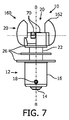
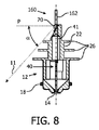
図5乃至図8は、第2の実施形態に従ったLED照明装置又はLEDランプ10を示している。以下で明らかとなるように、第2の実施形態に従ったLEDランプ10は、第1の実施形態に従ったLEDランプ10と、大部分で対応している。従って、以下の説明は、各実施形態の差異に焦点を当てている。各実施形態において同様の部分には、同一の参照符号が付されている。
5 to 8 show an LED lighting device or
第2の実施形態に従ったLEDランプ110は、図5乃至図8から分かるように、上位の熱散逸構造160の形状の点で、第1の実施形態とは異なる。第1の実施形態のように、アーチ型の縁64a,64bを具備する2つの別個の熱散逸素子162が、LED配置20の両側に備えられている。しかしながら、上位の熱散逸構造160は、特に図6において視認できるように、ずっと狭く、15°よりも大幅に小さいシェーディング角を達成する形状を持ち、結果、水平基準平面Pにおいて発せられる光のうちシェーディングされた部分68は、大幅に小さい(図6の網掛け部分参照)。
As can be seen from FIGS. 5 to 8, the LED lamp 110 according to the second embodiment differs from the first embodiment in the shape of the upper
熱散逸素子162は、それぞれ、半円型ディスクのような形状の平面素子であり、横軸Tに対して平行に配置されており、熱散逸素子162の間にLED素子70の両方が配置されている。熱散逸素子162は、LED配置20の上に長手方向に延在しているので、特定の機械的シールドも達成される。
Each of the
最終的な光分布が、図17(鉛直平面)及び図16(水平基準平面P)において、実線で示されている。ここから分かるように、0°乃至180°の角度において配置された薄い上位の熱散逸素子162による水平面(図16)における妨げは、第1の実施形態よりも大幅に少ない。鉛直平面(図17)では、上記分布は、第1の実施形態と略等しい。
The final light distribution is shown by a solid line in FIG. 17 (vertical plane) and FIG. 16 (horizontal reference plane P). As can be seen, the obstruction in the horizontal plane (FIG. 16) by the thin upper
図9乃至図13は、第3の実施形態に従ったLED照明装置又はLEDランプ210を示している。同様に、第3の実施形態と第1及び第2の実施形態との差異が、同様の部分には同様の参照符号が付されて、説明される。
9 to 13 show an LED lighting device or
第3の実施形態に従ったLEDランプ210は、2つの別個の熱散逸素子を有さず、横軸Tに沿って延在している単一の平面熱散逸素子262のみを有する上位の熱散逸構造260の形状の点で、前述の実施形態と異なる。アーチ型の縁64a,64bは、熱散逸素子262の長手方向端部を形成している。
The
前の実施形態のように、LED配置20は、互いに離れて配置された2つの個別のLED素子70を有している。LED素子70は、横軸Tに対して垂直にずらされて配置されており、熱散逸素子262の両側に配置されている。
As in the previous embodiment, the
図9乃至図13から分かるように、第3の実施形態では、LED素子70は、アーチ型の縁64a,64bを通っている横軸Tに沿って離れていない。また、平面担体板をそれぞれ具備する別個のLED素子70は、長手方向軸Lに沿って見た場合(図10)、横軸Tに対して平行な方向において、対向して配置されている。
As can be seen from FIGS. 9 to 13, in the third embodiment, the
第3の実施形態に従ったLEDランプ210において、熱散逸素子262は、熱散逸機能に加えて、シェーディング以外の光学的機能を持つ。LED素子70から発せられる光のための反射表面として機能するために、平面状の熱散逸素子262の両表面は、反射特性を得るべく高研磨されたアルミニウムである。しかしながら、高研磨されたアルミニウムは、むしろ低い熱放射係数を持つ。例えば、研磨されていないアルミニウムのヒートフィンの熱放射係数が0.8程度と高いのに対し、反射性を有するように研磨されたアルミニウムは、0.05程度の低い熱放射係数を持つ。アルミニウムの反射特性を利用できるようにするために、およそ0.6以上の熱放射係数を達成する透明被覆の薄層で表面266を被覆するのが好ましい。この透明被覆は、Rust-Oleum社の「High Temperature Top Coating 2500」などの透明なラッカーであってもよい。
In the
図13aは、熱散逸素子262の反射性側面266における単一のLED素子からの光の反射によって達成される光学的効果を概略的に示している。一方の側から見た場合、表面266における反射は、LED配置20が、2つのLED素子70を持つように見せ、表面266において反射された光を第2の光として見せ、表面266に仮想のLED素子を映す。好ましい実施形態では、LED素子70が両側に設けられるため、2つの物理的なLED素子70が熱散逸素子262によって分離されてはいるが、LED配置20は、全ての角度で、2つの別個のLED素子から光を発するようにみえる。
FIG. 13 a schematically illustrates the optical effect achieved by the reflection of light from a single LED element at the
図13bは、熱散逸素子262が、50%のミラーとして機能するように、小さな穴の構造を有する、他の実施形態の光学的効果を示している。表面266に入射する光の50%が反射される一方、他の50%が穴を通過する。この代替的な実施形態では、LED素子70の両方が、全ての光放射方向を照明する。
FIG. 13b shows the optical effect of another embodiment with a small hole structure so that the
本発明は、図面及び上記説明において、詳細に図示及び説明されてきたが、かかる図示及び説明は、例示的又は一例であって、制限的でないものと考えられるべきであり、即ち、本発明は、開示の実施形態に限定されない。 While the invention has been illustrated and described in detail in the drawings and foregoing description, such illustration and description are to be considered illustrative or exemplary and not restrictive; It is not limited to the disclosed embodiments.
例えば、1つだけのLED素子70を備えたり、又は、3以上のLED素子を備えたりするなどのLED配置20の異なる構造を用いることが可能である。上記実施形態のように2つのLED素子が用いられる場合、その配置は、例示の実施形態とは異なっていてもよい。例えば、第1及び第2の実施形態において、LED素子70は、横軸Tに対して垂直な方向にわずかにずらされているが、代替的に、横軸Tに沿って一列に正確に配置されてもよいし、又は、更にずらされていてもよい。
For example, different structures of the
上記実施形態の他の変形例として、図18乃至図20は、第1の実施形態に従ったLEDランプ10に対応しているが、下位の熱散逸構造24のディスク26の1つが異なる形状を持つ、LEDランプ310の代替的な第4の実施形態を示している。第1の実施形態とは対照的に、LED配置20の最も近くに配置されたディスク26は、円形状でなく、丸みを帯びた矩形状である。しかしながら、図19及び図20に示されるように、光放射方向11において、最も高い位置の矩形状のディスク26は、下位の円形状のディスク26より小さな拡がりを示している。従って、第1の実施形態と同様に、光放射方向11及び長手方向軸Lに対して平行な平面における照明角度αは、妨げを有しておらず、結果、光は自由に発せられる。
As another modification of the above embodiment, FIGS. 18 to 20 correspond to the
第4の実施形態において、ベース12の最も近くに配置される第3のディスク26は、図20において視認できるように、より小さな拡がりを持つ。
In the fourth embodiment, the
開示された実施形態の他の変形例が、図面、開示、及び、添付の請求項の研究から、本発明を実施する際、当該技術分野における当業者によって、理解及び実現され得る。請求項中、「有する」なる用語は、他の要素を除外せず、不定冠詞「a」又は「an」は、複数であることを除外しない。特定の特徴が相互に異なる従属項において言及されているという単なる事実、又は、特定の特徴が上記の詳細な説明における相互に異なる実施形態において開示されているという単なる事実は、これらの特徴の組み合わせが好適に用いられないということを示すものはない。請求項中の任意の参照符号は、本発明の範囲を限定するものとして解釈されるべきではない。 Other variations of the disclosed embodiments can be understood and realized by those skilled in the art in practicing the present invention from a study of the drawings, disclosure, and appended claims. In the claims, the term “comprising” does not exclude other elements and the indefinite article “a” or “an” does not exclude a plurality. The mere fact that certain features are referred to in mutually different dependent claims or the mere fact that certain features are disclosed in mutually different embodiments in the above detailed description is a combination of these features There is no indication that is not suitable for use. Any reference signs in the claims should not be construed as limiting the scope of the invention.
Claims (9)
少なくとも1つのLED素子を有するLED配置であって、長手方向軸に沿って、前記ベース要素とは離れて配置された前記LED配置と、
前記ベース要素と前記LED配置との間に配置された下位の熱散逸構造であって、当該下位の熱散逸構造は、熱伝導材料で作られた複数の平面熱散逸素子を有し、前記複数の平面熱散逸素子は、前記長手方向軸の方向に互いに離間して配置されている、下位の熱散逸構造と、を有し、
前記下位の熱散逸構造は、前記長手方向軸に沿った第1の長手方向位置において、前記長手方向軸に対して垂直な断面方向に第1の拡がりを持つとともに、第2の長手方向位置において、断面方向に第2の拡がりを持つように形成され、
前記第1の長手方向位置は、前記第2の長手方向位置よりも、前記LED配置の近くに配置され、前記第1の拡がりは、前記第2の拡がりよりも小さく、
前記平面熱散逸素子の各々が、前記長手方向軸に垂直な平面と最大で25°の角度をなす平面内に配置され、且つ
前記長手方向軸に沿って前記下位の熱散逸構造を通り抜ける通気道が存在しない、
照明装置。 Base elements for electrical contact and mechanical mounting;
An LED arrangement having at least one LED element, the LED arrangement being arranged away from the base element along a longitudinal axis;
A lower heat dissipation structure disposed between the base element and the LED arrangement, the lower heat dissipation structure having a plurality of planar heat dissipation elements made of a heat conductive material, The planar heat dissipating element has a lower heat dissipating structure , spaced apart from each other in the direction of the longitudinal axis ,
The lower heat dissipation structure has a first extension in a cross-sectional direction perpendicular to the longitudinal axis at a first longitudinal position along the longitudinal axis and a second longitudinal position. , Formed to have a second extension in the cross-sectional direction,
The first longitudinal position is located closer to the LED arrangement than the second longitudinal position, and the first spread is smaller than the second spread,
Each of the planar heat dissipation elements is disposed in a plane that forms an angle of up to 25 ° with a plane perpendicular to the longitudinal axis; and
There is no air passage through the lower heat dissipation structure along the longitudinal axis;
Lighting apparatus.
凹状の内部反射器表面及びマウント開口を具備する反射器体と、を有し、
前記照明装置は、前記LED配置が前記反射器体内に配置されるとともに、前記LED配置から発せられる光が前記内部反射器表面によって反射されるように、前記マウント開口内にマウントされる、照明配置。 The lighting device according to any one of claims 1 to 8 ,
A reflector body having a concave internal reflector surface and a mount aperture;
The lighting device is mounted in the mount opening such that the LED arrangement is disposed within the reflector body and light emitted from the LED arrangement is reflected by the internal reflector surface. .
Applications Claiming Priority (3)
| Application Number | Priority Date | Filing Date | Title |
|---|---|---|---|
| EP11305510.7 | 2011-04-29 | ||
| EP11305510 | 2011-04-29 | ||
| PCT/IB2012/052035 WO2012147026A1 (en) | 2011-04-29 | 2012-04-23 | Led lighting device with lower heat dissipating structure |
Publications (3)
| Publication Number | Publication Date |
|---|---|
| JP2014517447A JP2014517447A (en) | 2014-07-17 |
| JP2014517447A5 JP2014517447A5 (en) | 2015-06-18 |
| JP6042873B2 true JP6042873B2 (en) | 2016-12-14 |
Family
ID=46062678
Family Applications (1)
| Application Number | Title | Priority Date | Filing Date |
|---|---|---|---|
| JP2014506969A Active JP6042873B2 (en) | 2011-04-29 | 2012-04-23 | LED illuminating device having lower heat dissipation structure |
Country Status (7)
| Country | Link |
|---|---|
| US (1) | US9995438B2 (en) |
| EP (1) | EP2702315B8 (en) |
| JP (1) | JP6042873B2 (en) |
| CN (1) | CN103547849B (en) |
| BR (1) | BR112013027362A2 (en) |
| RU (1) | RU2604660C2 (en) |
| WO (1) | WO2012147026A1 (en) |
Families Citing this family (8)
| Publication number | Priority date | Publication date | Assignee | Title |
|---|---|---|---|---|
| US9797585B2 (en) | 2013-12-24 | 2017-10-24 | Amerlux Llc | Systems and methods for retrofitting existing lighting systems |
| WO2016062502A1 (en) * | 2014-10-21 | 2016-04-28 | Philips Lighting Holding B.V. | Light source assembly and method for producing the same |
| WO2016135276A1 (en) * | 2015-02-26 | 2016-09-01 | Philips Lighting Holding B.V. | Retrofit ligth bulb |
| CN105180115B (en) * | 2015-08-10 | 2018-05-01 | 漳州立达信光电子科技有限公司 | The electrical connector of LED light |
| US10627096B2 (en) * | 2015-11-26 | 2020-04-21 | Signify Holding B.V. | Lighting device |
| EP3260775B1 (en) | 2016-06-23 | 2019-03-13 | OSRAM GmbH | A heat sink, corresponding lighting device and method of use |
| SE541142C2 (en) * | 2016-09-19 | 2019-04-16 | Ikea Supply Ag | Lighting device with releasably connected shade |
| RU185884U1 (en) * | 2018-07-19 | 2018-12-24 | Артур Отарович Халатов | Plate for installing LED construction elements |
Family Cites Families (42)
| Publication number | Priority date | Publication date | Assignee | Title |
|---|---|---|---|---|
| JP3145838B2 (en) * | 1993-07-22 | 2001-03-12 | 富士写真フイルム株式会社 | Color thermal printer |
| US6796698B2 (en) * | 2002-04-01 | 2004-09-28 | Gelcore, Llc | Light emitting diode-based signal light |
| US6715900B2 (en) * | 2002-05-17 | 2004-04-06 | A L Lightech, Inc. | Light source arrangement |
| US7048412B2 (en) * | 2002-06-10 | 2006-05-23 | Lumileds Lighting U.S., Llc | Axial LED source |
| CN2699115Y (en) | 2004-05-18 | 2005-05-11 | 胡晓松 | LED luminous lamp holder |
| US7683772B2 (en) * | 2004-08-05 | 2010-03-23 | Whelen Engineering Company, Inc. | Integrated LED warning and vehicle lamp |
| JP4940883B2 (en) * | 2005-10-31 | 2012-05-30 | 豊田合成株式会社 | Light emitting device |
| US20070177392A1 (en) * | 2006-01-27 | 2007-08-02 | Vladimir Grigorik | Lighting fixture |
| CN101101090A (en) * | 2006-07-07 | 2008-01-09 | 启萌科技有限公司 | Luminaire |
| US7922359B2 (en) * | 2006-07-17 | 2011-04-12 | Liquidleds Lighting Corp. | Liquid-filled LED lamp with heat dissipation means |
| CN201028444Y (en) | 2006-10-26 | 2008-02-27 | 诸建平 | LED energy conserving lamp |
| EP1981218A1 (en) * | 2007-04-11 | 2008-10-15 | Nokia Siemens Networks Oy | Method and device for adjusting a transmission mode and system comprising such device |
| DE102007017900A1 (en) * | 2007-04-13 | 2008-10-16 | Noctron Holding S.A. | Lamp |
| DE112008002275A5 (en) * | 2007-09-19 | 2010-09-02 | Osram Gesellschaft mit beschränkter Haftung | Headlamp and its use |
| TWM334274U (en) | 2007-12-04 | 2008-06-11 | Cooler Master Co Ltd | A lighting device and cover with heat conduction structure |
| KR100972975B1 (en) | 2008-03-06 | 2010-07-29 | 삼성엘이디 주식회사 | LED Illumination Device |
| US20090273940A1 (en) * | 2008-05-01 | 2009-11-05 | Cao Group, Inc. | LED lighting device |
| KR101249609B1 (en) * | 2008-05-23 | 2013-04-01 | 후이저우 라이트 엔진 리미티드 | Non-glare reflective led lighting apparatus with heat sink mounting |
| JP5081746B2 (en) | 2008-07-04 | 2012-11-28 | パナソニック株式会社 | lamp |
| JP3145838U (en) | 2008-08-08 | 2008-10-23 | 株式会社カーメイト | LED bulb |
| DE102008047934B4 (en) | 2008-09-19 | 2015-02-26 | Osram Gmbh | Lighting device with a heat sink |
| KR101039073B1 (en) * | 2008-10-01 | 2011-06-08 | 주식회사 아모럭스 | Radiator and Bulb Type LED Lighting Apparatus Using the Same |
| DE102009008096B4 (en) | 2009-02-09 | 2016-10-27 | Osram Gmbh | Heat sink for a lighting device |
| JP2010198807A (en) * | 2009-02-23 | 2010-09-09 | Sharp Corp | Lighting device |
| DE102009011350A1 (en) | 2009-03-05 | 2010-09-09 | Osram Gesellschaft mit beschränkter Haftung | Lighting device with at least one heat sink |
| TWM362369U (en) * | 2009-03-20 | 2009-08-01 | Acpa Energy Conversion Devices Co Ltd | Reflective light wavelength modulation device |
| CN201386989Y (en) | 2009-03-26 | 2010-01-20 | 郑榕彬 | LED lighting lamp with secondary heat dissipation |
| CN101865372A (en) * | 2009-04-20 | 2010-10-20 | 富准精密工业(深圳)有限公司 | Light-emitting diode lamp |
| CN101871584A (en) * | 2009-04-23 | 2010-10-27 | 富士迈半导体精密工业(上海)有限公司 | Lighting device |
| US8952613B2 (en) * | 2009-05-12 | 2015-02-10 | Leroy E. Anderson | LED room light |
| US20110013413A1 (en) * | 2009-07-15 | 2011-01-20 | A-Sheng Yang | Vehicle lamp assembly improvement |
| CN101963337B (en) * | 2009-07-21 | 2013-04-24 | 富士迈半导体精密工业(上海)有限公司 | Lighting device |
| US20110050100A1 (en) | 2009-08-28 | 2011-03-03 | Joel Brad Bailey | Thermal Management of a Lighting System |
| US8593040B2 (en) | 2009-10-02 | 2013-11-26 | Ge Lighting Solutions Llc | LED lamp with surface area enhancing fins |
| RU93929U1 (en) * | 2009-12-15 | 2010-05-10 | Открытое акционерное общество "Завод ПРОТОН-МИЭТ" | ENERGY SAVING LIGHT |
| CN101839415B (en) | 2010-01-23 | 2013-01-09 | 鸿富锦精密工业(深圳)有限公司 | LED lighting lamp |
| RU95180U1 (en) * | 2010-01-25 | 2010-06-10 | Дмитрий Сергеевич Гвоздев | LED LAMP |
| US20110285267A1 (en) * | 2010-05-18 | 2011-11-24 | Ventiva, Inc. | Solid-state light bulb having an ion wind fan and a heat pipe |
| US20110310608A1 (en) * | 2010-06-18 | 2011-12-22 | Osram Sylvania Inc. | Led light source |
| US20120013237A1 (en) * | 2010-07-14 | 2012-01-19 | Wen-Jen Lee | Heat-dissipating structure of led bulb |
| CN102003647B (en) | 2010-12-11 | 2012-07-04 | 山东开元电子有限公司 | Omnibearing LED bulb lamp |
| US20120194054A1 (en) * | 2011-02-02 | 2012-08-02 | 3M Innovative Properties Company | Solid state light with optical diffuser and integrated thermal guide |
-
2012
- 2012-04-23 WO PCT/IB2012/052035 patent/WO2012147026A1/en active Application Filing
- 2012-04-23 EP EP12720651.4A patent/EP2702315B8/en active Active
- 2012-04-23 CN CN201280020941.0A patent/CN103547849B/en active Active
- 2012-04-23 BR BR112013027362A patent/BR112013027362A2/en not_active Application Discontinuation
- 2012-04-23 RU RU2013152949/07A patent/RU2604660C2/en active
- 2012-04-23 US US14/114,239 patent/US9995438B2/en active Active
- 2012-04-23 JP JP2014506969A patent/JP6042873B2/en active Active
Also Published As
| Publication number | Publication date |
|---|---|
| CN103547849A (en) | 2014-01-29 |
| BR112013027362A2 (en) | 2017-01-17 |
| US9995438B2 (en) | 2018-06-12 |
| US20140055998A1 (en) | 2014-02-27 |
| CN103547849B (en) | 2018-04-17 |
| WO2012147026A1 (en) | 2012-11-01 |
| EP2702315A1 (en) | 2014-03-05 |
| JP2014517447A (en) | 2014-07-17 |
| RU2013152949A (en) | 2015-06-10 |
| EP2702315B8 (en) | 2018-08-22 |
| EP2702315B1 (en) | 2018-06-13 |
| RU2604660C2 (en) | 2016-12-10 |
Similar Documents
| Publication | Publication Date | Title |
|---|---|---|
| JP6042873B2 (en) | LED illuminating device having lower heat dissipation structure | |
| JP6154373B2 (en) | LED illuminating device having upper heat dissipation structure | |
| JP6203833B2 (en) | Lamp with flexible printed circuit board | |
| JP2009129809A (en) | Lighting system | |
| US9964260B2 (en) | LED lighting device with improved light distribution | |
| US9651214B2 (en) | Light emitting diode (LED) bulb and lighting system having high and low beams | |
| JP6508552B2 (en) | LED light fixture | |
| JP3163443U (en) | LED lighting device | |
| US8789974B2 (en) | Lighting device | |
| JP6094618B2 (en) | lamp | |
| WO2013145049A1 (en) | Lamp | |
| KR102047686B1 (en) | Lighting apparatus | |
| JP6187527B2 (en) | lamp | |
| JP6137231B2 (en) | lamp | |
| JP5673705B2 (en) | Lighting device | |
| KR20140053521A (en) | Lighting apparatus | |
| KR20140136658A (en) | Lighting apparatus |
Legal Events
| Date | Code | Title | Description |
|---|---|---|---|
| A521 | Request for written amendment filed |
Free format text: JAPANESE INTERMEDIATE CODE: A523 Effective date: 20150421 |
|
| A621 | Written request for application examination |
Free format text: JAPANESE INTERMEDIATE CODE: A621 Effective date: 20150421 |
|
| RD03 | Notification of appointment of power of attorney |
Free format text: JAPANESE INTERMEDIATE CODE: A7423 Effective date: 20150604 |
|
| A977 | Report on retrieval |
Free format text: JAPANESE INTERMEDIATE CODE: A971007 Effective date: 20160218 |
|
| A131 | Notification of reasons for refusal |
Free format text: JAPANESE INTERMEDIATE CODE: A131 Effective date: 20160301 |
|
| A521 | Request for written amendment filed |
Free format text: JAPANESE INTERMEDIATE CODE: A523 Effective date: 20160531 |
|
| TRDD | Decision of grant or rejection written | ||
| A01 | Written decision to grant a patent or to grant a registration (utility model) |
Free format text: JAPANESE INTERMEDIATE CODE: A01 Effective date: 20161018 |
|
| A61 | First payment of annual fees (during grant procedure) |
Free format text: JAPANESE INTERMEDIATE CODE: A61 Effective date: 20161110 |
|
| R150 | Certificate of patent or registration of utility model |
Ref document number: 6042873 Country of ref document: JP Free format text: JAPANESE INTERMEDIATE CODE: R150 |
|
| S111 | Request for change of ownership or part of ownership |
Free format text: JAPANESE INTERMEDIATE CODE: R313113 |
|
| R350 | Written notification of registration of transfer |
Free format text: JAPANESE INTERMEDIATE CODE: R350 |
|
| R250 | Receipt of annual fees |
Free format text: JAPANESE INTERMEDIATE CODE: R250 |
|
| R250 | Receipt of annual fees |
Free format text: JAPANESE INTERMEDIATE CODE: R250 |
|
| R250 | Receipt of annual fees |
Free format text: JAPANESE INTERMEDIATE CODE: R250 |
|
| R250 | Receipt of annual fees |
Free format text: JAPANESE INTERMEDIATE CODE: R250 |
|
| R250 | Receipt of annual fees |
Free format text: JAPANESE INTERMEDIATE CODE: R250 |