EP3260775B1 - A heat sink, corresponding lighting device and method of use - Google Patents
A heat sink, corresponding lighting device and method of use Download PDFInfo
- Publication number
- EP3260775B1 EP3260775B1 EP17176359.2A EP17176359A EP3260775B1 EP 3260775 B1 EP3260775 B1 EP 3260775B1 EP 17176359 A EP17176359 A EP 17176359A EP 3260775 B1 EP3260775 B1 EP 3260775B1
- Authority
- EP
- European Patent Office
- Prior art keywords
- heat sink
- fins
- axis
- plate
- finned
- Prior art date
- Legal status (The legal status is an assumption and is not a legal conclusion. Google has not performed a legal analysis and makes no representation as to the accuracy of the status listed.)
- Not-in-force
Links
- 238000000034 method Methods 0.000 title claims description 11
- 239000012530 fluid Substances 0.000 claims description 20
- 230000005855 radiation Effects 0.000 claims description 15
- 238000001816 cooling Methods 0.000 description 7
- 230000008878 coupling Effects 0.000 description 3
- 238000010168 coupling process Methods 0.000 description 3
- 238000005859 coupling reaction Methods 0.000 description 3
- 230000007423 decrease Effects 0.000 description 3
- 239000000463 material Substances 0.000 description 3
- 239000000758 substrate Substances 0.000 description 3
- 238000009423 ventilation Methods 0.000 description 3
- 239000004020 conductor Substances 0.000 description 2
- 239000012809 cooling fluid Substances 0.000 description 2
- 229910052736 halogen Inorganic materials 0.000 description 2
- 150000002367 halogens Chemical class 0.000 description 2
- 230000007246 mechanism Effects 0.000 description 2
- 239000007769 metal material Substances 0.000 description 2
- 230000003068 static effect Effects 0.000 description 2
- 230000015572 biosynthetic process Effects 0.000 description 1
- 230000004907 flux Effects 0.000 description 1
- 210000003141 lower extremity Anatomy 0.000 description 1
- 239000002184 metal Substances 0.000 description 1
- 230000003287 optical effect Effects 0.000 description 1
- 230000009467 reduction Effects 0.000 description 1
- 238000005549 size reduction Methods 0.000 description 1
- 230000007704 transition Effects 0.000 description 1
Images


Classifications
-
- F—MECHANICAL ENGINEERING; LIGHTING; HEATING; WEAPONS; BLASTING
- F21—LIGHTING
- F21S—NON-PORTABLE LIGHTING DEVICES; SYSTEMS THEREOF; VEHICLE LIGHTING DEVICES SPECIALLY ADAPTED FOR VEHICLE EXTERIORS
- F21S41/00—Illuminating devices specially adapted for vehicle exteriors, e.g. headlamps
- F21S41/10—Illuminating devices specially adapted for vehicle exteriors, e.g. headlamps characterised by the light source
- F21S41/14—Illuminating devices specially adapted for vehicle exteriors, e.g. headlamps characterised by the light source characterised by the type of light source
- F21S41/141—Light emitting diodes [LED]
- F21S41/147—Light emitting diodes [LED] the main emission direction of the LED being angled to the optical axis of the illuminating device
- F21S41/148—Light emitting diodes [LED] the main emission direction of the LED being angled to the optical axis of the illuminating device the main emission direction of the LED being perpendicular to the optical axis
-
- B—PERFORMING OPERATIONS; TRANSPORTING
- B60—VEHICLES IN GENERAL
- B60Q—ARRANGEMENT OF SIGNALLING OR LIGHTING DEVICES, THE MOUNTING OR SUPPORTING THEREOF OR CIRCUITS THEREFOR, FOR VEHICLES IN GENERAL
- B60Q1/00—Arrangement of optical signalling or lighting devices, the mounting or supporting thereof or circuits therefor
- B60Q1/02—Arrangement of optical signalling or lighting devices, the mounting or supporting thereof or circuits therefor the devices being primarily intended to illuminate the way ahead or to illuminate other areas of way or environments
- B60Q1/04—Arrangement of optical signalling or lighting devices, the mounting or supporting thereof or circuits therefor the devices being primarily intended to illuminate the way ahead or to illuminate other areas of way or environments the devices being headlights
- B60Q1/18—Arrangement of optical signalling or lighting devices, the mounting or supporting thereof or circuits therefor the devices being primarily intended to illuminate the way ahead or to illuminate other areas of way or environments the devices being headlights being additional front lights
- B60Q1/20—Fog lights
-
- F—MECHANICAL ENGINEERING; LIGHTING; HEATING; WEAPONS; BLASTING
- F21—LIGHTING
- F21S—NON-PORTABLE LIGHTING DEVICES; SYSTEMS THEREOF; VEHICLE LIGHTING DEVICES SPECIALLY ADAPTED FOR VEHICLE EXTERIORS
- F21S41/00—Illuminating devices specially adapted for vehicle exteriors, e.g. headlamps
- F21S41/10—Illuminating devices specially adapted for vehicle exteriors, e.g. headlamps characterised by the light source
- F21S41/19—Attachment of light sources or lamp holders
- F21S41/192—Details of lamp holders, terminals or connectors
-
- F—MECHANICAL ENGINEERING; LIGHTING; HEATING; WEAPONS; BLASTING
- F21—LIGHTING
- F21V—FUNCTIONAL FEATURES OR DETAILS OF LIGHTING DEVICES OR SYSTEMS THEREOF; STRUCTURAL COMBINATIONS OF LIGHTING DEVICES WITH OTHER ARTICLES, NOT OTHERWISE PROVIDED FOR
- F21V29/00—Protecting lighting devices from thermal damage; Cooling or heating arrangements specially adapted for lighting devices or systems
- F21V29/50—Cooling arrangements
- F21V29/70—Cooling arrangements characterised by passive heat-dissipating elements, e.g. heat-sinks
- F21V29/74—Cooling arrangements characterised by passive heat-dissipating elements, e.g. heat-sinks with fins or blades
- F21V29/745—Cooling arrangements characterised by passive heat-dissipating elements, e.g. heat-sinks with fins or blades the fins or blades being planar and inclined with respect to the joining surface from which the fins or blades extend
-
- F—MECHANICAL ENGINEERING; LIGHTING; HEATING; WEAPONS; BLASTING
- F21—LIGHTING
- F21V—FUNCTIONAL FEATURES OR DETAILS OF LIGHTING DEVICES OR SYSTEMS THEREOF; STRUCTURAL COMBINATIONS OF LIGHTING DEVICES WITH OTHER ARTICLES, NOT OTHERWISE PROVIDED FOR
- F21V29/00—Protecting lighting devices from thermal damage; Cooling or heating arrangements specially adapted for lighting devices or systems
- F21V29/50—Cooling arrangements
- F21V29/70—Cooling arrangements characterised by passive heat-dissipating elements, e.g. heat-sinks
- F21V29/83—Cooling arrangements characterised by passive heat-dissipating elements, e.g. heat-sinks the elements having apertures, ducts or channels, e.g. heat radiation holes
-
- F—MECHANICAL ENGINEERING; LIGHTING; HEATING; WEAPONS; BLASTING
- F28—HEAT EXCHANGE IN GENERAL
- F28F—DETAILS OF HEAT-EXCHANGE AND HEAT-TRANSFER APPARATUS, OF GENERAL APPLICATION
- F28F13/00—Arrangements for modifying heat-transfer, e.g. increasing, decreasing
- F28F13/06—Arrangements for modifying heat-transfer, e.g. increasing, decreasing by affecting the pattern of flow of the heat-exchange media
- F28F13/08—Arrangements for modifying heat-transfer, e.g. increasing, decreasing by affecting the pattern of flow of the heat-exchange media by varying the cross-section of the flow channels
-
- F—MECHANICAL ENGINEERING; LIGHTING; HEATING; WEAPONS; BLASTING
- F21—LIGHTING
- F21S—NON-PORTABLE LIGHTING DEVICES; SYSTEMS THEREOF; VEHICLE LIGHTING DEVICES SPECIALLY ADAPTED FOR VEHICLE EXTERIORS
- F21S45/00—Arrangements within vehicle lighting devices specially adapted for vehicle exteriors, for purposes other than emission or distribution of light
- F21S45/40—Cooling of lighting devices
- F21S45/47—Passive cooling, e.g. using fins, thermal conductive elements or openings
-
- F—MECHANICAL ENGINEERING; LIGHTING; HEATING; WEAPONS; BLASTING
- F21—LIGHTING
- F21Y—INDEXING SCHEME ASSOCIATED WITH SUBCLASSES F21K, F21L, F21S and F21V, RELATING TO THE FORM OR THE KIND OF THE LIGHT SOURCES OR OF THE COLOUR OF THE LIGHT EMITTED
- F21Y2107/00—Light sources with three-dimensionally disposed light-generating elements
- F21Y2107/90—Light sources with three-dimensionally disposed light-generating elements on two opposite sides of supports or substrates
-
- F—MECHANICAL ENGINEERING; LIGHTING; HEATING; WEAPONS; BLASTING
- F21—LIGHTING
- F21Y—INDEXING SCHEME ASSOCIATED WITH SUBCLASSES F21K, F21L, F21S and F21V, RELATING TO THE FORM OR THE KIND OF THE LIGHT SOURCES OR OF THE COLOUR OF THE LIGHT EMITTED
- F21Y2115/00—Light-generating elements of semiconductor light sources
- F21Y2115/10—Light-emitting diodes [LED]
Definitions
- the description relates to heat sinks, which may find application e.g. in lighting devices.
- One or more embodiments may refer to heat sinks for lighting devices which employ electrically-powered light radiation sources such as solid-state light radiation sources, e.g. LED sources.
- electrically-powered light radiation sources such as solid-state light radiation sources, e.g. LED sources.
- Performance of LED sources may be widely affected by the temperature reached by the junction in operation. A temperature increase in the junction may lead to a reduction of the luminous flux output from the LED.
- the heat generated in operation by a light radiation source such as a LED source may be dissipated via a heat sink, which may be mounted on the rear side of the substrate carrying the source (it may be e.g. a substrate substantially similar to a Printed Circuit Board - PCB). Dissipation may be either active or passive, depending on the presence or absence of a fan or a blower.
- US 7 082 032 B1 describes a heat sink device comprising a base and a plurality of fins connected to the base, the latter fins extending away from the base at an non-orthogonal angle to the base.
- Document US 5 002 123 A describes a fluid heat exchanger for cooling an electronic component.
- the described solution comprises a plurality of spaced fins connected to the base, such fins being separated by fluid channels, wherein the cross-sectional area of the channels decreases from the inlet to the outlet.
- Document US 6 671 172 B2 describes a heat sink comprising a plurality of cooling fins, arranged about a core and coupled to a cooling device.
- the heat sink fins may have different shapes. According to one solution, the fins are curved. In another solution, the fins are knicked. In still another solution, the fins are both curved and knicked.
- the present disclosure relates to a heat sink according to the preamble of Claim 1, which is known e.g. from US 2014/055998 A1 . Also, documents US 2014/055999 A1 , DE 102007017900 , WO 2010/038982 A2 and JP 3134761 U may be of some interest for the disclosure.
- lamps or bulbs to be employed in the so-called retrofit of motor vehicle lamps i.e. bulbs adapted to replace halogen lamps.
- This may take place e.g. for front lights (e.g. fog lights) wherein, on the rear side of the bulb, apart from a reflector which may be associated to the lamp itself, a small space may be available. It is therefore desirable to achieve heat exchange structures having a high efficiency, due to the small available space and to the operating temperatures, which may be rather high.
- One or more embodiments aim at meeting such need.
- said object may be achieved thanks to a heat sink having the features set forth in the claims that follow.
- One or more embodiments may also concern a corresponding lighting device, as well as a corresponding method of use.
- One or more embodiments lead to the achievement of a heat sink adapted to work effectively even in the absence of an additional cooling system, which aims at increasing the velocity of the cooling fluid (e.g. cooling air).
- One or more embodiments may lead to a velocity increase of such a fluid by tilting the fins and by creating flow channels having a cross-section area which varies in the direction of the velocity vector of the fluid.
- a heat sink 10 may comprise a shaped body of a thermally conductive material, such as e.g. a metal material or a thermally conductive plastic material.
- heat sink 10 may be formed from one piece, or it may comprise a plurality of mutually connected elements or portions being in a thermal coupling relationship, as if they were formed as a single body.
- body 10 may include a portion 12, e.g. of a parallelepiped shape, which may include a surface sculpturing, adapted to have an elongated shape and extending along an axis X12.
- portion 12 may include two opposed faces or surfaces 12a, 12b, at least one of which may carry, arranged e.g. onto a substrate substantially similar to a Printed Circuit Board (PCB), an electrically powered light radiation source L, which in operation produces heat.
- PCB Printed Circuit Board
- mounting source(s) L onto heat sink 10 may take place according to a method as described in a Patent Application for Industrial Invention filed by the same Applicants on the same date.
- the source may be a solid-state light radiation source, e.g. a LED source.
- the light radiation source(s) L may be elements distinct from the embodiments.
- a heat sink 10 as exemplified herein may moreover comprise a finned portion 14, which is thermally coupled (e.g. made from one piece) with portion 12.
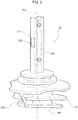
- finned portion 14 comprises a plurality of fins 140 (e.g. three fins 140a, 140b, 140c, but said number of fins is obviously not to be construed as limiting the embodiments) having an annular shape and extending around longitudinal axis X12.
- finned portion 14 may have a hollow structure, and therefore it may be traversed by an axial cavity 142 having, at the end facing towards portion 12, a flute-beak profile adapted e.g. to impart cavity 142 the shape of an axial through cavity along the length of finned portion 14, while providing a sort of cantilever formation 144 at which portion 12 is joined to portion 14 in thermal coupling conditions.
- an intermediate connecting portion denoted as 16, having a generally cylindrical shape, with the possible presence (in one or more embodiments: see for example Figure 1 and Figures 2 - 3 ) of protrusions / grooves, such as the groove denoted as 160, adapted to form cavities coupling heat sink 10 with an optical element.
- the latter may be e.g. a reflector R (see the simplified representation of the central part thereof in Figure 2 ), adapted to perform a reflection of the light radiation emitted by the light radiation source(s) L in operation.
- one or more embodiments may be used e.g. in order to obtain lighting devices which may be used in the automotive sector, e.g. as retrofit lamps or bulbs which may replace halogen lamps of motor vehicle lamps.
- heat sink 10 may support, primarily through finned portion 14, the dissipation of the heat generated in operation by light radiation source(s) L mounted on portion 12.
- Such a heat dissipating function may be performed via the fins 140 which are adapted, as previously stated, to comprise a thermally conductive material (e.g. a metal material).
- a thermally conductive material e.g. a metal material
- fins 140 may have a generally annular shape, although it is also possible to provide, as exemplified in Figure 1 , notches 146 which may lead to an overall size reduction.
- fins 140 may be arranged transversally to axis X12, i.e. approximately orthogonally to axis X12.
- At least some of the fins 140 may however be located obliquely to axis X12, as shown in Figure 2 .
- the term "obliquely” herein means that at least some of the fins 140 may be neither perpendicular nor parallel to axis X12.
- a first fin 140a, closest to portion 12 lies in a plane orthogonal or substantially orthogonal to axis X12.
- the following fins 140b, 140c etc. i.e. the fins which are located farther from portion 12, lie in planes which are oblique (tilted) to the plane orthogonal to axis X12.
- said subsequent fins 140b, 140c are parallel to each other, i.e. with the respective lying planes having the same tilting angle with respect to axis X12.
- said following fins 140b, 140c may be in turn oblique to one another, i.e. with the respective lying planes having different tilting angles to axis X12, e.g. with a tilting angle that increases with the distance from portions 12 and 16.
- fins 140 may have a generally planar shape.
- a generally annular structure may have a curved shape, such finned being ideally produced by a generating line which, instead of planar, may be curved, such as an exponential or a spline.
- pairs of fins 140 respectively define air flow channels (e.g. a first channel 1401, between fins 140a and 140b, and a second channel 1402 between fins 140b and 140c).
- such channels 1401, 1402 may have a width which varies (e.g. decreases) monotonously in a diametral direction with respect to the extension of fins 140 themselves.
- Figure 2 shows that channels 1401, 1402 have a tapered shape, e.g. with air inflow ends, at the bottom of the Figure, being wider than air outflow ends, at the top of the Figure.
- fins may be implemented so that the flow of fluid passing in the channel (e.g. 1401, 1402) defined between two adjoining fins 140 is constant along the channel; in other words, the tilting and the shape of fins 140 are defined so that the fluid velocity along the channel increases through the various sections of the fluid flow channel.
- One or more embodiments implement the operation method exemplified in Figure 2 .
- Such operation may find application e.g. in a lamp, e.g. a light of a vehicle such as a motor vehicle.
- heat sink 10 (or more generally the lighting device comprising heat sink 10 and the light radiation source(s) L mounted thereon) may be have axis X12 oriented horizontally and opposed surfaces 12a, 12b of portion 12 oriented vertically.
- flow channels 1401, 1402 of cooling fluid are oriented vertically, their "wider” ends facing downwards and their “narrower” ends facing upwards.
- a heat exchange mechanism may be achieved whereby, when ventilation air passes in channels 1401, 1402 (which may also be present in a different number from the two channels exemplified herein), it is adapted to remove the heat from heat sink 10, the air temperature being lowest at the lower extremities of fins 140 (see the four arrows at the bottom in Figure 2 ), where the channels 1401, 1402 exhibit their maximum width, and increasing while proceeding upwards, where the width of channels 1401, 1402 becomes smaller (see the two arrows at the top of Figure 2 ).
- the velocity of ventilation air may increase during the transition between the fins, because the area of the conduct decreases while the fluid temperature increases.
- fins 140 originate a movement resembling that of a blower or fan, so as to increase the efficiency of the heat exchange system. This is true also if light radiation source(s) L operate within static or nearly static air (e.g. within reflector R) and without the need of an additional cooling system.
- the heat source (s) (light radiation sources L) may be placed onto a generally plane plate structure (portion 12) arranged in a heat transfer relationship with finned portion 14, in conditions wherein fins 140 are arranged transversally to base plate 12.
- an array of fins 140 may be obtained which is adapted to originate a mechanism which gradually reduces temperature, by creating a gradient of temperature from fin 140a closest to heat source (light radiation source(s) L) towards fins 140b, 140c, i.e. proceeding towards the fins 140 which are farther away from portion 12.
- the lateral dimensions of base plate 12 are not influenced by the number of fins connected to the base: in one or more embodiments, the number of fins 140 is practically independent from the size of portion 12, because fins 140 are oriented transversally to axis X12.
- One or more embodiments may therefore concern a heat sink (e.g. 10), comprising:
- One or more embodiments may comprise a cylindrical portion (e.g. 16) arranged around said axis, between said plate-like portion and said finned portion.
- said plurality of fins may comprise at least one fin (e.g. 140a) extending orthogonally to said axis.
- said at least one fin may be arranged at the end of said plurality of fins, facing towards said plate-like portion.
- said plurality of fins may comprise at least one fin (e.g. 140b, 140c) which is oblique (i.e. neither orthogonal nor parallel) to said axis.
- said plurality of fins may comprise more than one fin oblique to said axis.
- said plurality of fins oblique to said axis are oblique to one another.
- One or more embodiments may include tapered fluid flow channels (e.g. 1401, 1402), extending between the fins of said plurality of fins, said tapered channels extending between a first side (e.g. at the bottom of Figure 2 ) and a second side (e.g. at the top of Figure 2 ) of the finned portion, said first and second sides being opposed to each other in a diametral direction with respect to said finned portion, wherein said tapered channels have wider fluid inflow ends (e.g. arrows at the bottom of Figure 2 , in the position corresponding to said first side of the finned portion), and narrower fluid outflow ends (e.g. arrows at the top of Figure 2 ) in the position corresponding to said second side of the finned portion.
- tapered fluid flow channels e.g. 1401, 1402
- the reference to relatively wider and narrower ends denotes the tapering direction of channels (e.g. 1401, 1402), with:
- said plate-like portion may extend parallel to said diametral direction (e.g. in the plane of the drawing of Figure 2 ).
- a lighting device may comprise:
- a method of using a heat sink or a lighting device may comprise arranging said heat sink with said axis oriented horizontally and said plate-like portion oriented vertically, optionally with said second side of the finned portion, wherein the fluid outflow ends may be located, arranged above said first side of finned portion, where the fluid inflow ends may be located.
Landscapes
- Engineering & Computer Science (AREA)
- General Engineering & Computer Science (AREA)
- Physics & Mathematics (AREA)
- Mechanical Engineering (AREA)
- Microelectronics & Electronic Packaging (AREA)
- Optics & Photonics (AREA)
- Thermal Sciences (AREA)
- Non-Portable Lighting Devices Or Systems Thereof (AREA)
- Cooling Or The Like Of Electrical Apparatus (AREA)
Description
- The description relates to heat sinks, which may find application e.g. in lighting devices.
- One or more embodiments may refer to heat sinks for lighting devices which employ electrically-powered light radiation sources such as solid-state light radiation sources, e.g. LED sources.
- An important issue in the operation of solid-state lighting devices, such as lighting devices employing LED sources, resides in the thermal management of the lighting device.
- Performance of LED sources may be widely affected by the temperature reached by the junction in operation. A temperature increase in the junction may lead to a reduction of the luminous flux output from the LED.
- The heat generated in operation by a light radiation source such as a LED source may be dissipated via a heat sink, which may be mounted on the rear side of the substrate carrying the source (it may be e.g. a substrate substantially similar to a Printed Circuit Board - PCB). Dissipation may be either active or passive, depending on the presence or absence of a fan or a blower.
- In automotive applications, for instance, various heat sink solutions have been proposed.
- For example,
US 7 082 032 B1 describes a heat sink device comprising a base and a plurality of fins connected to the base, the latter fins extending away from the base at an non-orthogonal angle to the base. - Document
US 6 533 028 B2 describes a heat sink having a plurality of fins disposed on a surface of a heat conducting plate, and being non-parallel to the heat receiving surface. An apparatus is also described comprising a heat sink together with a cooling device coupled to the heat sink. - Document
US 5 002 123 A describes a fluid heat exchanger for cooling an electronic component. The described solution comprises a plurality of spaced fins connected to the base, such fins being separated by fluid channels, wherein the cross-sectional area of the channels decreases from the inlet to the outlet. - Document
US 6 671 172 B2 describes a heat sink comprising a plurality of cooling fins, arranged about a core and coupled to a cooling device. The heat sink fins may have different shapes. According to one solution, the fins are curved. In another solution, the fins are knicked. In still another solution, the fins are both curved and knicked. The present disclosure relates to a heat sink according to the preamble ofClaim 1, which is known e.g. fromUS 2014/055998 A1 . Also, documentsUS 2014/055999 A1 ,DE 102007017900 ,WO 2010/038982 A2 andJP 3134761 U - Despite the extensive research and innovation in the field, which emerges e.g. from documents as previously mentioned, the need is still felt for improved solutions.
- Attention must be paid e.g. to the automotive sector, e.g. as regards lamps or bulbs to be employed in the so-called retrofit of motor vehicle lamps, i.e. bulbs adapted to replace halogen lamps. This may take place e.g. for front lights (e.g. fog lights) wherein, on the rear side of the bulb, apart from a reflector which may be associated to the lamp itself, a small space may be available. It is therefore desirable to achieve heat exchange structures having a high efficiency, due to the small available space and to the operating temperatures, which may be rather high.
- One or more embodiments aim at meeting such need.
- According to one or more embodiments, said object may be achieved thanks to a heat sink having the features set forth in the claims that follow.
- One or more embodiments may also concern a corresponding lighting device, as well as a corresponding method of use.
- The claims are an integral part of the technical description provided herein with reference to the embodiments.
- One or more embodiments lead to the achievement of a heat sink adapted to work effectively even in the absence of an additional cooling system, which aims at increasing the velocity of the cooling fluid (e.g. cooling air). One or more embodiments may lead to a velocity increase of such a fluid by tilting the fins and by creating flow channels having a cross-section area which varies in the direction of the velocity vector of the fluid.
- One or more embodiments will now be described, by way of non-limiting example only, with reference to the annexed Figures, wherein:
-
Figure 1 is an overall perspective view of a heat sink according to one or more embodiments, -
Figure 2 shows possible methods of use of a heat sink according to one or more embodiments, and -
Figure 3 is a cross-sectional view along line III-III ofFigure 2 . - It will be appreciated that, for clarity and simplicity of illustration, the various Figures may not be all drawn to the same scale, and may moreover refer to different embodiments.
- In the following description, various specific details are given to provide a thorough understanding of various exemplary embodiments of the present specification. The embodiments may be practiced without one or several specific details, or with other methods, components, materials, etc. In other instances, well-known structures, materials or operations are not shown or described in detail to avoid obscuring various aspects of the embodiments.
- Reference throughout this specification to "one embodiment" or "an embodiment" means that a particular feature, structure, or characteristic described in connection with the embodiment is included in at least one embodiment. Thus, the possible appearances of the phrases "in one embodiment" or "in an embodiment" in various places throughout this specification are not necessarily all referring to the same embodiment. Furthermore, particular features, structures, or characteristics may be combined in any suitable manner in one or more embodiments.
- The headings provided herein are for convenience only, and therefore do not interpret the extent of protection or scope of the embodiments.
- In one or more embodiments, a
heat sink 10 may comprise a shaped body of a thermally conductive material, such as e.g. a metal material or a thermally conductive plastic material. - In one or more embodiments,
heat sink 10 may be formed from one piece, or it may comprise a plurality of mutually connected elements or portions being in a thermal coupling relationship, as if they were formed as a single body. - In one or more embodiments,
body 10 may include aportion 12, e.g. of a parallelepiped shape, which may include a surface sculpturing, adapted to have an elongated shape and extending along an axis X12. - In one or more embodiments,
portion 12 may include two opposed faces orsurfaces - In one or more embodiments, mounting source(s) L onto
heat sink 10 may take place according to a method as described in a Patent Application for Industrial Invention filed by the same Applicants on the same date. - In one or more embodiments, the source may be a solid-state light radiation source, e.g. a LED source.
- It will be appreciated that the light radiation source(s) L, as well as the corresponding PCB supports, may be elements distinct from the embodiments.
- In one or more embodiments, a
heat sink 10 as exemplified herein may moreover comprise afinned portion 14, which is thermally coupled (e.g. made from one piece) withportion 12. - According to the invention,
finned portion 14 comprises a plurality of fins 140 (e.g. threefins - In one or more embodiments,
finned portion 14 may have a hollow structure, and therefore it may be traversed by anaxial cavity 142 having, at the end facing towardsportion 12, a flute-beak profile adapted e.g. to impartcavity 142 the shape of an axial through cavity along the length offinned portion 14, while providing a sort ofcantilever formation 144 at whichportion 12 is joined toportion 14 in thermal coupling conditions. - In one or more embodiments, between
portion 12 andportion 14 there may be provided an intermediate connecting portion, denoted as 16, having a generally cylindrical shape, with the possible presence (in one or more embodiments: see for exampleFigure 1 andFigures 2 - 3 ) of protrusions / grooves, such as the groove denoted as 160, adapted to form cavitiescoupling heat sink 10 with an optical element. The latter may be e.g. a reflector R (see the simplified representation of the central part thereof inFigure 2 ), adapted to perform a reflection of the light radiation emitted by the light radiation source(s) L in operation. - As stated in the foregoing, one or more embodiments may be used e.g. in order to obtain lighting devices which may be used in the automotive sector, e.g. as retrofit lamps or bulbs which may replace halogen lamps of motor vehicle lamps.
- In one or more embodiments,
heat sink 10 may support, primarily throughfinned portion 14, the dissipation of the heat generated in operation by light radiation source(s) L mounted onportion 12. - Such a heat dissipating function may be performed via the
fins 140 which are adapted, as previously stated, to comprise a thermally conductive material (e.g. a metal material). - In one or more embodiments,
fins 140 may have a generally annular shape, although it is also possible to provide, as exemplified inFigure 1 ,notches 146 which may lead to an overall size reduction. - In one or more embodiments, fins 140 may be arranged transversally to axis X12, i.e. approximately orthogonally to axis X12.
- In one or more embodiments, at least some of the
fins 140 may however be located obliquely to axis X12, as shown inFigure 2 . The term "obliquely" herein means that at least some of thefins 140 may be neither perpendicular nor parallel to axis X12. - For example, as may be seen in the view of
Figure 2 , in one or more embodiments afirst fin 140a, closest to portion 12 (e.g. adjoining intermediate portion 16) lies in a plane orthogonal or substantially orthogonal to axis X12. - On the contrary, the following
fins portion 12, lie in planes which are oblique (tilted) to the plane orthogonal to axis X12. - In one or more embodiments, said
subsequent fins - In one or more embodiments as exemplified herein, said following
fins portions - In one or more embodiments as exemplified herein
fins 140 may have a generally planar shape. - In one or more embodiments, however, while keeping a generally annular structure, they may have a curved shape, such finned being ideally produced by a generating line which, instead of planar, may be curved, such as an exponential or a spline.
- Also independently from the specific implementation details which have been previously mentioned, according to the invention the purpose is achieved of having pairs of
fins 140 respectively define air flow channels (e.g. afirst channel 1401, betweenfins second channel 1402 betweenfins - In one or more embodiments,
such channels fins 140 themselves. - According to the invention,
Figure 2 shows thatchannels - Despite the presence of such variable width, fins may be implemented so that the flow of fluid passing in the channel (e.g. 1401, 1402) defined between two adjoining
fins 140 is constant along the channel; in other words, the tilting and the shape offins 140 are defined so that the fluid velocity along the channel increases through the various sections of the fluid flow channel. - One or more embodiments implement the operation method exemplified in
Figure 2 . - Such operation may find application e.g. in a lamp, e.g. a light of a vehicle such as a motor vehicle.
- In this operating mode, heat sink 10 (or more generally the lighting device comprising
heat sink 10 and the light radiation source(s) L mounted thereon) may be have axis X12 oriented horizontally andopposed surfaces portion 12 oriented vertically. - In this situation,
flow channels - In these conditions, a heat exchange mechanism may be achieved whereby, when ventilation air passes in
channels 1401, 1402 (which may also be present in a different number from the two channels exemplified herein), it is adapted to remove the heat fromheat sink 10, the air temperature being lowest at the lower extremities of fins 140 (see the four arrows at the bottom inFigure 2 ), where thechannels channels Figure 2 ). - In this way, the velocity of ventilation air may increase during the transition between the fins, because the area of the conduct decreases while the fluid temperature increases.
- In this way,
fins 140 originate a movement resembling that of a blower or fan, so as to increase the efficiency of the heat exchange system. This is true also if light radiation source(s) L operate within static or nearly static air (e.g. within reflector R) and without the need of an additional cooling system. - In comparison with conventional solutions, e.g. the solution according to
US 5 002 123 A (wherein the heat source is located on a base plate, the fins being connected orthogonally to said base plate), or the solution according toUS 6 671 172 B2 (wherein the heat sources are located on a surface of a massive metal core, wherefrom the fins depart, subsequently growing in a radial direction), in one or more embodiments the heat source (s) (light radiation sources L) may be placed onto a generally plane plate structure (portion 12) arranged in a heat transfer relationship with finnedportion 14, in conditions whereinfins 140 are arranged transversally tobase plate 12. - In this way an array of
fins 140 may be obtained which is adapted to originate a mechanism which gradually reduces temperature, by creating a gradient of temperature fromfin 140a closest to heat source (light radiation source(s) L) towardsfins fins 140 which are farther away fromportion 12. - This enables arranging the heat source very close to (i.e., virtually contacting) the adjoining heat-sensitive parts, thus achieving a more compact heat sink.
- For example, in one or more embodiments the lateral dimensions of
base plate 12 are not influenced by the number of fins connected to the base: in one or more embodiments, the number offins 140 is practically independent from the size ofportion 12, becausefins 140 are oriented transversally to axis X12. - One or more embodiments may therefore concern a heat sink (e.g. 10), comprising:
- a plate-like portion (e.g. 12) extending along an axis (e.g. X12) with opposed surfaces (e.g. 12a, 12b) for mounting at least one heat source (e.g. L), and
- a finned portion (e.g. 14) thermally coupled with the plate-like portion and comprising a plurality of annular fins (e.g. 140) extending around said axis.
- One or more embodiments may comprise a cylindrical portion (e.g. 16) arranged around said axis, between said plate-like portion and said finned portion.
- In one or more embodiments, said plurality of fins may comprise at least one fin (e.g. 140a) extending orthogonally to said axis.
- In one or more embodiments, said at least one fin may be arranged at the end of said plurality of fins, facing towards said plate-like portion.
- In one or more embodiments, said plurality of fins may comprise at least one fin (e.g. 140b, 140c) which is oblique (i.e. neither orthogonal nor parallel) to said axis.
- In one or more embodiments, said plurality of fins may comprise more than one fin oblique to said axis.
- In one or more embodiments, said plurality of fins oblique to said axis are oblique to one another.
- One or more embodiments may include tapered fluid flow channels (e.g. 1401, 1402), extending between the fins of said plurality of fins, said tapered channels extending between a first side (e.g. at the bottom of
Figure 2 ) and a second side (e.g. at the top ofFigure 2 ) of the finned portion, said first and second sides being opposed to each other in a diametral direction with respect to said finned portion, wherein said tapered channels have wider fluid inflow ends (e.g. arrows at the bottom ofFigure 2 , in the position corresponding to said first side of the finned portion), and narrower fluid outflow ends (e.g. arrows at the top ofFigure 2 ) in the position corresponding to said second side of the finned portion. - The reference to relatively wider and narrower ends denotes the tapering direction of channels (e.g. 1401, 1402), with:
- fluid inflow ends being wider than fluid outflow ends, and
- fluid outflow ends being narrower than fluid inflow ends.
- In one or more embodiments, said plate-like portion may extend parallel to said diametral direction (e.g. in the plane of the drawing of
Figure 2 ). - In one or more embodiments, a lighting device may comprise:
- a heat sink according to one or more embodiments, and
- an electrically-powered light radiation source, optionally a LED source, adapted to constitute said heat source mounted on at least one of said opposed surfaces of the plate-like portion.
- A method of using a heat sink or a lighting device according to one or more embodiments may comprise arranging said heat sink with said axis oriented horizontally and said plate-like portion oriented vertically, optionally with said second side of the finned portion, wherein the fluid outflow ends may be located, arranged above said first side of finned portion, where the fluid inflow ends may be located.
- Without prejudice to the basic principles, the details and the embodiments may vary, even appreciably, with respect to what has been described herein by way of non-limiting example only, without departing from the extent of protection.
- The extent of protection is defined by the annexed claims.
Claims (11)
- A heat sink (10), including:- a plate-like portion (12) extending along an axis (X12) and having opposed mounting surfaces (12a, 12b) for at least one heat source (L),- a finned portion (14) thermally coupled with the plate-like portion (12) and including a plurality of annular fins (140) extending around said axis (X12),wherein the heat sink is characterized in that it includes tapered fluid flow channels (1401, 1402) between the fins of said plurality of fins (140), said tapered channels (1401, 1402) extending between first and second sides of the finned portion (14), said first and second sides opposed in a diametral direction of said finned portion (14), wherein said tapered channels (1401, 1402) have wider fluid inflow ends at said first side of the finned portion (14) and narrower fluid outflow ends at said second side of the finned portion (14) .
- The heat sink (10) of claim 1, including a cylindrical portion (16) arranged around said axis (X12) between said plate-like portion (12) and said finned portion (14).
- The heat sink (10) of claim 1 or claim 2, wherein said plurality of fins (140) include at least one fin (140a) extending orthogonal to said axis (X12).
- The heat sink (10) of claim 3, wherein said at least one fin (140a) is located at the end of said plurality of the fins (140) facing towards said plate-like portion (12).
- The heat sink (10) of any of the previous claims, wherein said plurality of fins (140) include at least one fin (140b, 140c) oblique to said axis (X12).
- The heat sink (10) of claim 5, wherein said plurality of fins (140) include plural fins (140b, 140c) oblique to said axis (X12).
- The heat sink (10) of claim 6, wherein said plural fins (140b, 140c) oblique to said axis (X12) are oblique to one another.
- The heat sink (10) of claim 1, wherein said plate-like portion (12) extends parallel to said diametral direction.
- A lighting device, including:- a heat sink (10) according to any of claims 1 to 8,- an electrically powered light radiation source (L), preferably a LED source, mounted at at least one of said opposed surfaces (12a, 12b) of the plate-like portion (12).
- A method of using the heat sink (10) of any of claims 1 to 8 or the lighting device of claim 9, the method including arranging said heat sink (10) with said axis (X12) arranged horizontally and said plate-like portion (12) arranged vertically.
- The method of claim 10, for use of a heat sink (10) according to claim 1 or claim 8, the method including arranging said heat sink (10) with said second side of the finned portion (14) arranged above said first side of the finned portion (14).
Applications Claiming Priority (1)
| Application Number | Priority Date | Filing Date | Title |
|---|---|---|---|
| ITUA20164619 | 2016-06-23 |
Publications (2)
| Publication Number | Publication Date |
|---|---|
| EP3260775A1 EP3260775A1 (en) | 2017-12-27 |
| EP3260775B1 true EP3260775B1 (en) | 2019-03-13 |
Family
ID=57209776
Family Applications (1)
| Application Number | Title | Priority Date | Filing Date |
|---|---|---|---|
| EP17176359.2A Not-in-force EP3260775B1 (en) | 2016-06-23 | 2017-06-16 | A heat sink, corresponding lighting device and method of use |
Country Status (3)
| Country | Link |
|---|---|
| US (1) | US10378751B2 (en) |
| EP (1) | EP3260775B1 (en) |
| CN (1) | CN107543120B (en) |
Families Citing this family (3)
| Publication number | Priority date | Publication date | Assignee | Title |
|---|---|---|---|---|
| US10598338B1 (en) * | 2018-12-03 | 2020-03-24 | Guangzhou Tai Da Electric Appliance Co., Ltd | Vehicle headlight and method of making the same |
| CN110500555B (en) * | 2019-08-27 | 2021-08-20 | 李居强 | Heat dissipation device and lighting device |
| USD987167S1 (en) * | 2020-03-23 | 2023-05-23 | Osram Gmbh | Heatsink for a lamp |
Family Cites Families (14)
| Publication number | Priority date | Publication date | Assignee | Title |
|---|---|---|---|---|
| US5002123A (en) | 1989-04-20 | 1991-03-26 | Microelectronics And Computer Technology Corporation | Low pressure high heat transfer fluid heat exchanger |
| JP2002368468A (en) | 2001-06-07 | 2002-12-20 | Matsushita Electric Ind Co Ltd | Heat sink, its manufacturing method and cooler using the same |
| US6671172B2 (en) | 2001-09-10 | 2003-12-30 | Intel Corporation | Electronic assemblies with high capacity curved fin heat sinks |
| US7082032B1 (en) | 2003-08-25 | 2006-07-25 | Hewlett-Packard Development Company, L.P. | Heat dissipation device with tilted fins |
| DE102007017900A1 (en) * | 2007-04-13 | 2008-10-16 | Noctron Holding S.A. | Lamp |
| JP3134761U (en) * | 2007-06-12 | 2007-08-23 | 株式会社昭電 | Lighting device |
| KR101039073B1 (en) * | 2008-10-01 | 2011-06-08 | 주식회사 아모럭스 | Radiator and Bulb Type LED Lighting Apparatus Using the Same |
| JP5381561B2 (en) * | 2008-11-28 | 2014-01-08 | 富士電機株式会社 | Semiconductor cooling device |
| CN201351897Y (en) * | 2009-02-09 | 2009-11-25 | 索士亚科技股份有限公司 | Heat dissipating structure of high power LED projecting lamp |
| DE102009011350A1 (en) * | 2009-03-05 | 2010-09-09 | Osram Gesellschaft mit beschränkter Haftung | Lighting device with at least one heat sink |
| CN102102827B (en) * | 2009-12-16 | 2012-03-28 | 杨华祥 | Novel movie and stage lighting lamp |
| US20110254421A1 (en) * | 2010-04-15 | 2011-10-20 | Novel Concepts, Inc. | Cooling Structure For Bulb Shaped Solid State Lamp |
| US9995438B2 (en) * | 2011-04-29 | 2018-06-12 | Lumileds Llc | LED lighting device with lower heat dissipating structure |
| CN103492789B (en) * | 2011-04-29 | 2016-09-07 | 皇家飞利浦有限公司 | There is the LED illumination device of top heat dissipation structure |
-
2017
- 2017-06-16 EP EP17176359.2A patent/EP3260775B1/en not_active Not-in-force
- 2017-06-22 US US15/629,811 patent/US10378751B2/en not_active Expired - Fee Related
- 2017-06-22 CN CN201710480585.5A patent/CN107543120B/en not_active Expired - Fee Related
Non-Patent Citations (1)
| Title |
|---|
| None * |
Also Published As
| Publication number | Publication date |
|---|---|
| CN107543120A (en) | 2018-01-05 |
| CN107543120B (en) | 2021-02-26 |
| US20170370552A1 (en) | 2017-12-28 |
| US10378751B2 (en) | 2019-08-13 |
| EP3260775A1 (en) | 2017-12-27 |
Similar Documents
| Publication | Publication Date | Title |
|---|---|---|
| US8911125B2 (en) | Circuit module, light emitting module, and automotive lamp | |
| EP2276973B1 (en) | Non-glare reflective led lighting apparatus with heat sink mounting | |
| JP5596328B2 (en) | Single block radiators for optical modules in automotive lighting or signaling devices | |
| JP5342553B2 (en) | Vehicle lighting | |
| US10962215B2 (en) | Active radiator with omnidirectional air convection and stage lighting fixture using the same | |
| EP3260775B1 (en) | A heat sink, corresponding lighting device and method of use | |
| US10337690B2 (en) | Automotive LED module with heat sink and fan | |
| CN104583669A (en) | Lighting device with a LED and an improved reflective collimator | |
| US20100220487A1 (en) | Lighting assembly and heat exchange apparatus for uniform heat dissipation | |
| US9857047B2 (en) | Cooling member and motor vehicle lighting or signaling device comprising such a member | |
| US8727584B2 (en) | LED bulb structure | |
| EP3578873A1 (en) | Lighting fixture for vehicle | |
| CN103827579A (en) | Heat sink and lighting apparatus having same | |
| KR101652161B1 (en) | Lighting apparatus | |
| KR101272748B1 (en) | Led headlamp for vehicle | |
| JP5902973B2 (en) | Heat sink for in-vehicle LED lamp | |
| CN108626694B (en) | Device for cooling light source | |
| CN110914590A (en) | Cooling body and vehicle searchlight | |
| KR20100094210A (en) | Heat sink and led package having the same | |
| JP2009245833A (en) | Lighting fixture for vehicle | |
| KR101548323B1 (en) | heat sink and heat radiator apparatus having thereof | |
| US10247403B2 (en) | Heat sink and lighting apparatus | |
| CN217131147U (en) | Radiator for heat source, lighting and/or signal indicating device and motor vehicle | |
| WO2010094178A1 (en) | Lighting assembly and heat exchange apparatus for uniform heat dissipation | |
| KR20150019787A (en) | Heatsink increasing heat emitting performance and Head lamp having it for vehicle |
Legal Events
| Date | Code | Title | Description |
|---|---|---|---|
| PUAI | Public reference made under article 153(3) epc to a published international application that has entered the european phase |
Free format text: ORIGINAL CODE: 0009012 |
|
| STAA | Information on the status of an ep patent application or granted ep patent |
Free format text: STATUS: THE APPLICATION HAS BEEN PUBLISHED |
|
| AK | Designated contracting states |
Kind code of ref document: A1 Designated state(s): AL AT BE BG CH CY CZ DE DK EE ES FI FR GB GR HR HU IE IS IT LI LT LU LV MC MK MT NL NO PL PT RO RS SE SI SK SM TR |
|
| AX | Request for extension of the european patent |
Extension state: BA ME |
|
| RAP1 | Party data changed (applicant data changed or rights of an application transferred) |
Owner name: OSRAM GMBH Owner name: OSRAM S.P.A. - SOCIETA' RIUNITE OSRAM EDISON CLERI |
|
| STAA | Information on the status of an ep patent application or granted ep patent |
Free format text: STATUS: REQUEST FOR EXAMINATION WAS MADE |
|
| 17P | Request for examination filed |
Effective date: 20180613 |
|
| RBV | Designated contracting states (corrected) |
Designated state(s): AL AT BE BG CH CY CZ DE DK EE ES FI FR GB GR HR HU IE IS IT LI LT LU LV MC MK MT NL NO PL PT RO RS SE SI SK SM TR |
|
| GRAP | Despatch of communication of intention to grant a patent |
Free format text: ORIGINAL CODE: EPIDOSNIGR1 |
|
| RIC1 | Information provided on ipc code assigned before grant |
Ipc: F21S 45/47 20180101ALI20180905BHEP Ipc: F21Y 107/90 20160101ALN20180905BHEP Ipc: F21V 29/74 20150101AFI20180905BHEP Ipc: F21S 41/19 20180101ALI20180905BHEP Ipc: F21S 41/148 20180101ALI20180905BHEP Ipc: F21Y 115/10 20160101ALN20180905BHEP |
|
| STAA | Information on the status of an ep patent application or granted ep patent |
Free format text: STATUS: GRANT OF PATENT IS INTENDED |
|
| INTG | Intention to grant announced |
Effective date: 20181011 |
|
| GRAS | Grant fee paid |
Free format text: ORIGINAL CODE: EPIDOSNIGR3 |
|
| GRAA | (expected) grant |
Free format text: ORIGINAL CODE: 0009210 |
|
| STAA | Information on the status of an ep patent application or granted ep patent |
Free format text: STATUS: THE PATENT HAS BEEN GRANTED |
|
| AK | Designated contracting states |
Kind code of ref document: B1 Designated state(s): AL AT BE BG CH CY CZ DE DK EE ES FI FR GB GR HR HU IE IS IT LI LT LU LV MC MK MT NL NO PL PT RO RS SE SI SK SM TR |
|
| REG | Reference to a national code |
Ref country code: GB Ref legal event code: FG4D |
|
| REG | Reference to a national code |
Ref country code: CH Ref legal event code: EP Ref country code: AT Ref legal event code: REF Ref document number: 1108207 Country of ref document: AT Kind code of ref document: T Effective date: 20190315 |
|
| REG | Reference to a national code |
Ref country code: IE Ref legal event code: FG4D |
|
| REG | Reference to a national code |
Ref country code: DE Ref legal event code: R096 Ref document number: 602017002656 Country of ref document: DE |
|
| REG | Reference to a national code |
Ref country code: NL Ref legal event code: MP Effective date: 20190313 |
|
| REG | Reference to a national code |
Ref country code: LT Ref legal event code: MG4D |
|
| PG25 | Lapsed in a contracting state [announced via postgrant information from national office to epo] |
Ref country code: NO Free format text: LAPSE BECAUSE OF FAILURE TO SUBMIT A TRANSLATION OF THE DESCRIPTION OR TO PAY THE FEE WITHIN THE PRESCRIBED TIME-LIMIT Effective date: 20190613 Ref country code: FI Free format text: LAPSE BECAUSE OF FAILURE TO SUBMIT A TRANSLATION OF THE DESCRIPTION OR TO PAY THE FEE WITHIN THE PRESCRIBED TIME-LIMIT Effective date: 20190313 Ref country code: SE Free format text: LAPSE BECAUSE OF FAILURE TO SUBMIT A TRANSLATION OF THE DESCRIPTION OR TO PAY THE FEE WITHIN THE PRESCRIBED TIME-LIMIT Effective date: 20190313 Ref country code: LT Free format text: LAPSE BECAUSE OF FAILURE TO SUBMIT A TRANSLATION OF THE DESCRIPTION OR TO PAY THE FEE WITHIN THE PRESCRIBED TIME-LIMIT Effective date: 20190313 |
|
| PG25 | Lapsed in a contracting state [announced via postgrant information from national office to epo] |
Ref country code: NL Free format text: LAPSE BECAUSE OF FAILURE TO SUBMIT A TRANSLATION OF THE DESCRIPTION OR TO PAY THE FEE WITHIN THE PRESCRIBED TIME-LIMIT Effective date: 20190313 Ref country code: BG Free format text: LAPSE BECAUSE OF FAILURE TO SUBMIT A TRANSLATION OF THE DESCRIPTION OR TO PAY THE FEE WITHIN THE PRESCRIBED TIME-LIMIT Effective date: 20190613 Ref country code: GR Free format text: LAPSE BECAUSE OF FAILURE TO SUBMIT A TRANSLATION OF THE DESCRIPTION OR TO PAY THE FEE WITHIN THE PRESCRIBED TIME-LIMIT Effective date: 20190614 Ref country code: HR Free format text: LAPSE BECAUSE OF FAILURE TO SUBMIT A TRANSLATION OF THE DESCRIPTION OR TO PAY THE FEE WITHIN THE PRESCRIBED TIME-LIMIT Effective date: 20190313 Ref country code: RS Free format text: LAPSE BECAUSE OF FAILURE TO SUBMIT A TRANSLATION OF THE DESCRIPTION OR TO PAY THE FEE WITHIN THE PRESCRIBED TIME-LIMIT Effective date: 20190313 Ref country code: LV Free format text: LAPSE BECAUSE OF FAILURE TO SUBMIT A TRANSLATION OF THE DESCRIPTION OR TO PAY THE FEE WITHIN THE PRESCRIBED TIME-LIMIT Effective date: 20190313 |
|
| REG | Reference to a national code |
Ref country code: AT Ref legal event code: MK05 Ref document number: 1108207 Country of ref document: AT Kind code of ref document: T Effective date: 20190313 |
|
| PG25 | Lapsed in a contracting state [announced via postgrant information from national office to epo] |
Ref country code: PT Free format text: LAPSE BECAUSE OF FAILURE TO SUBMIT A TRANSLATION OF THE DESCRIPTION OR TO PAY THE FEE WITHIN THE PRESCRIBED TIME-LIMIT Effective date: 20190713 Ref country code: AL Free format text: LAPSE BECAUSE OF FAILURE TO SUBMIT A TRANSLATION OF THE DESCRIPTION OR TO PAY THE FEE WITHIN THE PRESCRIBED TIME-LIMIT Effective date: 20190313 Ref country code: EE Free format text: LAPSE BECAUSE OF FAILURE TO SUBMIT A TRANSLATION OF THE DESCRIPTION OR TO PAY THE FEE WITHIN THE PRESCRIBED TIME-LIMIT Effective date: 20190313 Ref country code: IT Free format text: LAPSE BECAUSE OF FAILURE TO SUBMIT A TRANSLATION OF THE DESCRIPTION OR TO PAY THE FEE WITHIN THE PRESCRIBED TIME-LIMIT Effective date: 20190313 Ref country code: CZ Free format text: LAPSE BECAUSE OF FAILURE TO SUBMIT A TRANSLATION OF THE DESCRIPTION OR TO PAY THE FEE WITHIN THE PRESCRIBED TIME-LIMIT Effective date: 20190313 Ref country code: SK Free format text: LAPSE BECAUSE OF FAILURE TO SUBMIT A TRANSLATION OF THE DESCRIPTION OR TO PAY THE FEE WITHIN THE PRESCRIBED TIME-LIMIT Effective date: 20190313 Ref country code: RO Free format text: LAPSE BECAUSE OF FAILURE TO SUBMIT A TRANSLATION OF THE DESCRIPTION OR TO PAY THE FEE WITHIN THE PRESCRIBED TIME-LIMIT Effective date: 20190313 Ref country code: ES Free format text: LAPSE BECAUSE OF FAILURE TO SUBMIT A TRANSLATION OF THE DESCRIPTION OR TO PAY THE FEE WITHIN THE PRESCRIBED TIME-LIMIT Effective date: 20190313 |
|
| PG25 | Lapsed in a contracting state [announced via postgrant information from national office to epo] |
Ref country code: SM Free format text: LAPSE BECAUSE OF FAILURE TO SUBMIT A TRANSLATION OF THE DESCRIPTION OR TO PAY THE FEE WITHIN THE PRESCRIBED TIME-LIMIT Effective date: 20190313 Ref country code: PL Free format text: LAPSE BECAUSE OF FAILURE TO SUBMIT A TRANSLATION OF THE DESCRIPTION OR TO PAY THE FEE WITHIN THE PRESCRIBED TIME-LIMIT Effective date: 20190313 |
|
| REG | Reference to a national code |
Ref country code: DE Ref legal event code: R097 Ref document number: 602017002656 Country of ref document: DE |
|
| PG25 | Lapsed in a contracting state [announced via postgrant information from national office to epo] |
Ref country code: AT Free format text: LAPSE BECAUSE OF FAILURE TO SUBMIT A TRANSLATION OF THE DESCRIPTION OR TO PAY THE FEE WITHIN THE PRESCRIBED TIME-LIMIT Effective date: 20190313 Ref country code: IS Free format text: LAPSE BECAUSE OF FAILURE TO SUBMIT A TRANSLATION OF THE DESCRIPTION OR TO PAY THE FEE WITHIN THE PRESCRIBED TIME-LIMIT Effective date: 20190713 |
|
| PLBE | No opposition filed within time limit |
Free format text: ORIGINAL CODE: 0009261 |
|
| STAA | Information on the status of an ep patent application or granted ep patent |
Free format text: STATUS: NO OPPOSITION FILED WITHIN TIME LIMIT |
|
| PG25 | Lapsed in a contracting state [announced via postgrant information from national office to epo] |
Ref country code: DK Free format text: LAPSE BECAUSE OF FAILURE TO SUBMIT A TRANSLATION OF THE DESCRIPTION OR TO PAY THE FEE WITHIN THE PRESCRIBED TIME-LIMIT Effective date: 20190313 Ref country code: MC Free format text: LAPSE BECAUSE OF FAILURE TO SUBMIT A TRANSLATION OF THE DESCRIPTION OR TO PAY THE FEE WITHIN THE PRESCRIBED TIME-LIMIT Effective date: 20190313 |
|
| 26N | No opposition filed |
Effective date: 20191216 |
|
| PG25 | Lapsed in a contracting state [announced via postgrant information from national office to epo] |
Ref country code: SI Free format text: LAPSE BECAUSE OF FAILURE TO SUBMIT A TRANSLATION OF THE DESCRIPTION OR TO PAY THE FEE WITHIN THE PRESCRIBED TIME-LIMIT Effective date: 20190313 |
|
| REG | Reference to a national code |
Ref country code: BE Ref legal event code: MM Effective date: 20190630 |
|
| PG25 | Lapsed in a contracting state [announced via postgrant information from national office to epo] |
Ref country code: TR Free format text: LAPSE BECAUSE OF FAILURE TO SUBMIT A TRANSLATION OF THE DESCRIPTION OR TO PAY THE FEE WITHIN THE PRESCRIBED TIME-LIMIT Effective date: 20190313 |
|
| PG25 | Lapsed in a contracting state [announced via postgrant information from national office to epo] |
Ref country code: IE Free format text: LAPSE BECAUSE OF NON-PAYMENT OF DUE FEES Effective date: 20190616 |
|
| PG25 | Lapsed in a contracting state [announced via postgrant information from national office to epo] |
Ref country code: BE Free format text: LAPSE BECAUSE OF NON-PAYMENT OF DUE FEES Effective date: 20190630 Ref country code: LU Free format text: LAPSE BECAUSE OF NON-PAYMENT OF DUE FEES Effective date: 20190616 |
|
| PG25 | Lapsed in a contracting state [announced via postgrant information from national office to epo] |
Ref country code: FR Free format text: LAPSE BECAUSE OF NON-PAYMENT OF DUE FEES Effective date: 20190630 |
|
| REG | Reference to a national code |
Ref country code: CH Ref legal event code: PL |
|
| PG25 | Lapsed in a contracting state [announced via postgrant information from national office to epo] |
Ref country code: LI Free format text: LAPSE BECAUSE OF NON-PAYMENT OF DUE FEES Effective date: 20200630 Ref country code: CH Free format text: LAPSE BECAUSE OF NON-PAYMENT OF DUE FEES Effective date: 20200630 |
|
| PG25 | Lapsed in a contracting state [announced via postgrant information from national office to epo] |
Ref country code: CY Free format text: LAPSE BECAUSE OF FAILURE TO SUBMIT A TRANSLATION OF THE DESCRIPTION OR TO PAY THE FEE WITHIN THE PRESCRIBED TIME-LIMIT Effective date: 20190313 |
|
| PG25 | Lapsed in a contracting state [announced via postgrant information from national office to epo] |
Ref country code: MT Free format text: LAPSE BECAUSE OF FAILURE TO SUBMIT A TRANSLATION OF THE DESCRIPTION OR TO PAY THE FEE WITHIN THE PRESCRIBED TIME-LIMIT Effective date: 20190313 Ref country code: HU Free format text: LAPSE BECAUSE OF FAILURE TO SUBMIT A TRANSLATION OF THE DESCRIPTION OR TO PAY THE FEE WITHIN THE PRESCRIBED TIME-LIMIT; INVALID AB INITIO Effective date: 20170616 |
|
| GBPC | Gb: european patent ceased through non-payment of renewal fee |
Effective date: 20210616 |
|
| PG25 | Lapsed in a contracting state [announced via postgrant information from national office to epo] |
Ref country code: GB Free format text: LAPSE BECAUSE OF NON-PAYMENT OF DUE FEES Effective date: 20210616 |
|
| PG25 | Lapsed in a contracting state [announced via postgrant information from national office to epo] |
Ref country code: MK Free format text: LAPSE BECAUSE OF FAILURE TO SUBMIT A TRANSLATION OF THE DESCRIPTION OR TO PAY THE FEE WITHIN THE PRESCRIBED TIME-LIMIT Effective date: 20190313 |
|
| PGFP | Annual fee paid to national office [announced via postgrant information from national office to epo] |
Ref country code: DE Payment date: 20220620 Year of fee payment: 6 |
|
| P01 | Opt-out of the competence of the unified patent court (upc) registered |
Effective date: 20230821 |
|
| REG | Reference to a national code |
Ref country code: DE Ref legal event code: R119 Ref document number: 602017002656 Country of ref document: DE |
|
| PG25 | Lapsed in a contracting state [announced via postgrant information from national office to epo] |
Ref country code: DE Free format text: LAPSE BECAUSE OF NON-PAYMENT OF DUE FEES Effective date: 20240103 |