JP6039272B2 - Inkjet recording apparatus and inkjet recording method - Google Patents
Inkjet recording apparatus and inkjet recording method Download PDFInfo
- Publication number
- JP6039272B2 JP6039272B2 JP2012150636A JP2012150636A JP6039272B2 JP 6039272 B2 JP6039272 B2 JP 6039272B2 JP 2012150636 A JP2012150636 A JP 2012150636A JP 2012150636 A JP2012150636 A JP 2012150636A JP 6039272 B2 JP6039272 B2 JP 6039272B2
- Authority
- JP
- Japan
- Prior art keywords
- recording
- nozzle
- detection
- nozzles
- failure
- Prior art date
- Legal status (The legal status is an assumption and is not a legal conclusion. Google has not performed a legal analysis and makes no representation as to the accuracy of the status listed.)
- Active
Links
Images


Classifications
-
- B—PERFORMING OPERATIONS; TRANSPORTING
- B41—PRINTING; LINING MACHINES; TYPEWRITERS; STAMPS
- B41J—TYPEWRITERS; SELECTIVE PRINTING MECHANISMS, i.e. MECHANISMS PRINTING OTHERWISE THAN FROM A FORME; CORRECTION OF TYPOGRAPHICAL ERRORS
- B41J2/00—Typewriters or selective printing mechanisms characterised by the printing or marking process for which they are designed
- B41J2/005—Typewriters or selective printing mechanisms characterised by the printing or marking process for which they are designed characterised by bringing liquid or particles selectively into contact with a printing material
- B41J2/01—Ink jet
- B41J2/135—Nozzles
- B41J2/165—Preventing or detecting of nozzle clogging, e.g. cleaning, capping or moistening for nozzles
- B41J2/16517—Cleaning of print head nozzles
-
- B—PERFORMING OPERATIONS; TRANSPORTING
- B41—PRINTING; LINING MACHINES; TYPEWRITERS; STAMPS
- B41J—TYPEWRITERS; SELECTIVE PRINTING MECHANISMS, i.e. MECHANISMS PRINTING OTHERWISE THAN FROM A FORME; CORRECTION OF TYPOGRAPHICAL ERRORS
- B41J11/00—Devices or arrangements of selective printing mechanisms, e.g. ink-jet printers or thermal printers, for supporting or handling copy material in sheet or web form
- B41J11/66—Applications of cutting devices
- B41J11/70—Applications of cutting devices cutting perpendicular to the direction of paper feed
- B41J11/706—Applications of cutting devices cutting perpendicular to the direction of paper feed using a cutting tool mounted on a reciprocating carrier
-
- B—PERFORMING OPERATIONS; TRANSPORTING
- B41—PRINTING; LINING MACHINES; TYPEWRITERS; STAMPS
- B41J—TYPEWRITERS; SELECTIVE PRINTING MECHANISMS, i.e. MECHANISMS PRINTING OTHERWISE THAN FROM A FORME; CORRECTION OF TYPOGRAPHICAL ERRORS
- B41J2/00—Typewriters or selective printing mechanisms characterised by the printing or marking process for which they are designed
- B41J2/005—Typewriters or selective printing mechanisms characterised by the printing or marking process for which they are designed characterised by bringing liquid or particles selectively into contact with a printing material
- B41J2/01—Ink jet
- B41J2/21—Ink jet for multi-colour printing
- B41J2/2132—Print quality control characterised by dot disposition, e.g. for reducing white stripes or banding
- B41J2/2146—Print quality control characterised by dot disposition, e.g. for reducing white stripes or banding for line print heads
-
- B—PERFORMING OPERATIONS; TRANSPORTING
- B41—PRINTING; LINING MACHINES; TYPEWRITERS; STAMPS
- B41J—TYPEWRITERS; SELECTIVE PRINTING MECHANISMS, i.e. MECHANISMS PRINTING OTHERWISE THAN FROM A FORME; CORRECTION OF TYPOGRAPHICAL ERRORS
- B41J2/00—Typewriters or selective printing mechanisms characterised by the printing or marking process for which they are designed
- B41J2/005—Typewriters or selective printing mechanisms characterised by the printing or marking process for which they are designed characterised by bringing liquid or particles selectively into contact with a printing material
- B41J2/01—Ink jet
- B41J2/135—Nozzles
- B41J2/165—Preventing or detecting of nozzle clogging, e.g. cleaning, capping or moistening for nozzles
- B41J2/16517—Cleaning of print head nozzles
- B41J2002/16573—Cleaning process logic, e.g. for determining type or order of cleaning processes
Description
本発明は、インクジェット記録装置およびインクジェット記録方法に関する。特に、吐出不良な記録素子を検出し、吐出不良な記録素子で記録すべきデータを他の記録素子で補完する不吐補完方法に関する。 The present invention relates to an ink jet recording apparatus and an ink jet recording method. In particular, the present invention relates to a discharge failure complement method for detecting defective printing elements and supplementing data to be printed with defective printing elements with other printing elements.
インクジェット記録装置では、インクを滴として吐出するノズルを多数備えた記録ヘッドを用いているが、これら複数のノズルにおいては、記録中に突発的に吐出不良が発生し、記録した画像にスジやムラが発生することがある。このような突発的な吐出不良は、主にノズル近傍の異物やノズル内部に混入した気泡などによって引き起こされるので、ほとんどの場合、記録ヘッドに対するメンテナンス処理によって解決される。しかしながら、連続紙に記録する場合や、カット紙であっても連続印刷するような場合には、出力の高速性が重視されるので、比較的多大な時間を有するメンテナンス処理を、記録中に頻繁に行うことは現実的ではない。 Inkjet recording apparatuses use a recording head having a large number of nozzles that eject ink as droplets. However, in these nozzles, ejection failures occur suddenly during recording, resulting in streaks and unevenness in the recorded image. May occur. Such a sudden ejection failure is mainly caused by a foreign substance in the vicinity of the nozzle or bubbles mixed in the nozzle, and is almost always solved by a maintenance process for the recording head. However, when recording on continuous paper, or when continuous printing is performed even with cut paper, high-speed output is important, so maintenance processing that requires a relatively long time is frequently performed during recording. It is not realistic to do it.
このような場合、吐出不良のノズルが記録するべき記録データを他のノズルで補って記録するいわゆる不吐補完処理を行うことが出来れば、メンテナンス処理を行わなくても、画像上にスジやムラなどの弊害を招くことは無い。また、このような不吐補完処理は、突発的に発生した吐出不良だけでなく、ヒータ断線やノズル内部のごみ詰まり等に起因した通常のメンテナンス処理では回復できない吐出不良に対しても有効である。 In such a case, if the so-called non-discharge complementing process in which the recording data to be recorded by the nozzles with defective ejection is supplemented by other nozzles and recorded can be performed, streak and unevenness can be displayed on the image without performing the maintenance process. It will not cause any negative effects. Such non-discharge complementation processing is effective not only for ejection failures that occur suddenly, but also for ejection failures that cannot be recovered by normal maintenance processing due to heater disconnection or nozzle clogging. .
特許文献1には、記録動作前の吐出状態を検出して補正する比較的精度の高い第1の不吐補完処理と、記録動作中の吐出状態を検出して補正する比較的処理速度の速い第2の不吐補完処理とを実行可能なインクジェット方法が開示されている。このような2段階の不吐補完処理が用意されれば、定常的な吐出不良についても突発的な吐出不良についても適切に対応し、スジやムラのない画像を安定して出力することが出来る。 Japanese Patent Application Laid-Open No. 2004-151867 discloses a relatively high-accuracy first discharge failure complement process for detecting and correcting a discharge state before a printing operation, and a relatively high processing speed for detecting and correcting a discharge state during a printing operation. An inkjet method capable of executing the second discharge failure complement process is disclosed. If such a two-stage discharge failure complement process is prepared, it is possible to appropriately deal with both steady discharge failures and sudden discharge failures and stably output images without streaks or unevenness. .
ところで、不吐補完処理では、吐出不良と検出されたノズルの情報を何らかの記憶手段に記憶し、この情報を下に、吐出不良ノズルの記録データを他の正常ノズルの記録データに振り分ける。よって、第2の不吐補完処理を行いながら記録動作を長時間連続すると、吐出不良と認定されているノズルの数は増える一方で、吐出不良と認定されているノズルの記録を正常ノズルで補いきれなくなる場合がある。また、残された正常ノズルの吐出頻度がどんどん増加するので、その寿命を縮めてしまう懸念もある。その一方で、突発的な吐出不良は、特にメンテナンス処理を行わなくても記録動作中に自然回復することも多く、ひとたび吐出不良ノズルと判定した結果が長期間更新されないことは、正常なノズルとしての復帰を妨げる機会損失となってしまう。よって、吐出不良と検出されたノズルの情報については、適切なタイミングでリセットされることが望まれる。 By the way, in the discharge failure complement process, information on the nozzles detected as ejection failure is stored in some storage means, and the recording data of the ejection failure nozzles is distributed to the recording data of other normal nozzles based on this information. Therefore, if the recording operation is continued for a long time while performing the second discharge failure complement process, the number of nozzles that are recognized as ejection failures increases, while the recording of nozzles that are identified as ejection failures is supplemented with normal nozzles. You may not be able to understand. Further, since the discharge frequency of the remaining normal nozzles increases more and more, there is a concern that the service life may be shortened. On the other hand, sudden discharge failures often recover spontaneously during a printing operation without particularly performing maintenance processing, and the fact that the result of determining a discharge failure nozzle is not updated for a long time is a normal nozzle. It will be a loss of opportunity that hinders the return. Therefore, it is desirable to reset the information on the nozzles detected as ejection failure at an appropriate timing.
しかしながら、特許文献1に記載の不吐補完処理においては、第1の不吐補完処理で検出した吐出不良情報も第2の不吐補完処理で検出した吐出不良情報も同様に記憶し、双方の情報が合算して反映されるような不吐補完処理が行われている。よって、記録動作中に突発的に発生した吐出不良の情報をリセットすると、記録動作前から吐出不良と認定された定常的な吐出不良情報までがクリアされてしまい、リセット直後の画像において、スジやムラなどの画像弊害が現れてしまう。
However, in the discharge failure complement process described in
本発明は上記問題点を解決するためになされたものである。よって、その目的とするところは、精度の高い第1の不吐補完処理と処理速度の速い第2の不吐補完処理とを併用しながら、頻繁なメンテナンス処理を伴うことなく、定常的な吐出不良も突発的な吐出不良も適切に対応可能な不吐補完処理を実行することである。 The present invention has been made to solve the above problems. Therefore, the purpose is to use the first discharge failure complement processing with high accuracy and the second discharge failure complement processing with a high processing speed in combination, and perform steady discharge without frequent maintenance processing. This is to execute a discharge failure complement process capable of appropriately dealing with defects and sudden discharge failures.
そのために本発明は、インクを吐出する複数のノズルを配列して構成される記録ヘッドを用い、記録媒体に複数の画像を連続記録するインクジェット記録装置において、前記連続記録中ではないタイミングにおいて、吐出不良を回復するためのメンテナンス処理が行われた前記記録ヘッドにおける吐出不良のノズルを検出する第1検出手段と、該第1検出手段により検出された吐出不良のノズルに関する情報である第1検出不良ノズル情報を記憶する第1記憶手段と、前記連続記録中において、前記記録ヘッドにおける吐出不良のノズルを検出する第2検出手段と、該第2検出手段により検出された吐出不良のノズルに関する情報である第2検出不良ノズル情報を記憶する第2記憶手段と、前記第1検出不良ノズル情報と前記第2検出不良ノズル情報とに基づいて、検出された吐出不良のノズルを用いずに吐出不良でないノズルを用いて前記記録媒体に前記複数の画像を連続記録する記録手段と、前記第2検出手段によって検出された吐出不良のノズルの数が所定数を超えたタイミングで吐出不良を回復するためのメンテナンス処理が実行された後に、前記第1検出不良ノズル情報をリセットせずに前記第2検出不良ノズル情報をリセットするリセット手段とを備えることを特徴とする。 Therefore, the present invention uses an ink jet recording apparatus that continuously records a plurality of images on a recording medium using a recording head configured by arranging a plurality of nozzles that eject ink, and ejects the ink at a timing not during the continuous recording. First detection means for detecting defective nozzles in the recording head that has undergone maintenance processing for recovering defects, and first detection defects that are information relating to defective nozzles detected by the first detection means Information relating to a first storage means for storing nozzle information, a second detection means for detecting defective nozzles in the recording head during the continuous recording, and a defective nozzle detected by the second detection means. Second storage means for storing certain second detection failure nozzle information; the first detection failure nozzle information; and the second detection failure nozzle. Based on the Le information, recording means for continuously recording the plurality of images on the recording medium using the nozzles not defective ejection without using the detected discharge failure of a nozzle, thus detected to the second detecting means After the maintenance process for recovering the ejection failure is performed at the timing when the number of the ejection failure nozzles exceeds a predetermined number, the second detection failure nozzle information is not reset without resetting the first detection failure nozzle information. And resetting means for resetting.
また、インクを吐出する複数のノズルを配列して構成される記録ヘッドを用い、記録媒体に複数の画像を連続記録するインクジェット記録方法において、前記連続記録中ではないタイミングにおいて、吐出不良を回復するためのメンテナンス処理が行われた前記記録ヘッドにおける吐出不良のノズルを検出する第1検出工程と、該第1検出工程において検出された吐出不良のノズルに関する情報である第1検出不良ノズル情報を記憶する第1記憶工程と、前記連続記録中において、前記記録ヘッドにおける吐出不良のノズルを検出する第2検出工程と、該第2検出工程において検出された吐出不良のノズルに関する情報である第2検出不良ノズル情報を記憶する第2記憶工程と、前記第1検出不良ノズル情報と前記第2検出不良ノズル情報とに基づいて、検出された吐出不良のノズルを用いずに吐出不良でないノズルを用いて前記記録媒体に前記複数の画像を連続記録する記録工程と、前記第2検出工程によって検出された吐出不良のノズルの数が所定数を超えたタイミングで吐出不良を回復するためのメンテナンス処理が実行された後に、前記第1検出不良ノズル情報をリセットせずに、前記第2検出不良ノズル情報をリセットするリセット工程とを有することを特徴とする。
さらに、インクを吐出する複数のノズルを配列して構成される記録ヘッドを用い、記録媒体に複数の画像を連続記録するための記録制御装置であって、前記連続記録中ではないタイミングにおいて、吐出不良を回復するためのメンテナンス処理が行われた前記記録ヘッドにおいて検出された吐出不良のノズルの情報である第1検出不良ノズル情報と、前記連続記録中の前記記録ヘッドにおいて検出された吐出不良のノズルの情報である第2検出不良ノズル情報と、をそれぞれ記憶する記憶手段と、前記記憶手段に記憶された情報を制御する制御手段と、を備え、前記制御手段は、前記第2検出不良ノズル情報における吐出不良のノズルの数が所定数を超えたタイミングで吐出不良を回復するためのメンテナンス処理が実行された後に、前記記憶手段における前記第1検出不良ノズル情報をリセットせずに、前記第2検出不良ノズル情報をリセットすることを特徴とする。
In addition, in an inkjet recording method in which a plurality of images are continuously recorded on a recording medium using a recording head configured by arranging a plurality of nozzles that eject ink, ejection failure is recovered at a timing not during the continuous recording. A first detection step for detecting defective nozzles in the recording head for which maintenance processing has been performed, and first detection defective nozzle information that is information relating to defective nozzles detected in the first detection step. to a first storage step, during the continuous recording, the second detection step of detecting a discharge failure of a nozzle in the recording head, the second detection is information about faulty nozzles detected in the second detection step A second storage step for storing defective nozzle information; the first detection defective nozzle information; and the second detection defective nozzle information; Based on a recording step of a plurality of images continuously recorded on the recording medium using the nozzles not defective ejection without using the detected ejection failure nozzle, the second detection step to thus detected discharge failure Reset that resets the second detection failure nozzle information without resetting the first detection failure nozzle information after the maintenance process for recovering the discharge failure is executed at a timing when the number of nozzles exceeds a predetermined number. And a process.
Furthermore, the present invention is a recording control apparatus for continuously recording a plurality of images on a recording medium using a recording head configured by arranging a plurality of nozzles for discharging ink, and discharging at a timing not during the continuous recording. The first detection failure nozzle information which is information of the ejection failure nozzle detected in the recording head subjected to the maintenance process for recovering the failure, and the ejection failure detected in the recording head during the continuous recording. Storage means for storing second detection failure nozzle information which is nozzle information, and control means for controlling the information stored in the storage means, wherein the control means includes the second detection failure nozzle. After the maintenance process for recovering the ejection failure at the timing when the number of ejection failure nozzles in the information exceeds a predetermined number, Without resetting the first detecting defective nozzle information in means and resetting said second detecting defective nozzle information.
本発明によれば、連続記録中においてもメンテナンス処理などによって記録動作を中断することなく、迅速に吐出不良ノズルを検出してこれを補完することが可能となる。そして、適切なタイミングで必要最低限のメンテナンス処理を実行しながらも、メンテナンス処理によって回復不可能な吐出不良ノズルについては、その情報を維持し、その記録位置に対する補完を継続することができる。 According to the present invention, it is possible to quickly detect defective nozzles and compensate for them without interrupting the recording operation by maintenance processing or the like even during continuous recording. Then, while executing the minimum necessary maintenance process at an appropriate timing, it is possible to maintain the information about the ejection failure nozzles that cannot be recovered by the maintenance process, and continue the supplement to the recording position.
以下に図面を参照して本発明の実施形態を詳細に説明する。 Embodiments of the present invention will be described below in detail with reference to the drawings.
(第1実施形態)
図1は本実施形態に係るインクジェット記録装置1(以下、「記録装置1」という。)を示す外観図である。記録装置1内においてロール状に保持されている記録媒体3は、後述する記録部5に給紙された後、記録データに従った記録が行われる。記録後の記録媒体3は図のようにX方向に引き出される。ユーザは、操作部15に設けられた各種スイッチを用いて、記録媒体3のサイズ指定、オンライン/オフラインの切り替えなど、記録装置1に対する各種コマンドの入力を行うことができる。
(First embodiment)
FIG. 1 is an external view showing an ink jet recording apparatus 1 (hereinafter referred to as “
図2は記録装置1の内部構成を示す断面図である。同図に示すように、記録装置1は、給紙部2と記録部5と検査部6と切断部8とを備える。本実施形態において給紙部2はロール状に保持されている記録媒体3を引き出して、搬送方向の下流に配置された記録部5へこれを供給する。
FIG. 2 is a cross-sectional view showing the internal configuration of the
記録部5は給紙部2から搬送されてきた記録媒体3に対して画像および画像形成とは関係ないノズルの吐出状態を検査するための検査パターンを記録する。記録部5は記録媒体3を所定のサイズに切断するための目印となるカットマークパターン、ノズルの吐出状態を維持するためのフラッシングパターン、ノズル検査パターン等も記録する。
The
記録部5は異なる色のインクを吐出するフルライン型の記録ヘッド4a〜4dを備えており、記録ヘッド4a〜4dには記録媒体3の幅方向(Y方向)に沿ったノズル列が設けられている。本実施形態において、このようなノズル列は記録媒体3の搬送方向(X方向)へ複数配置されている。各ノズル列は、所定のピッチでY方向に配列する複数のノズルによって構成されており、Y方向と交差する方向に一定の速度で搬送される記録媒体に対し、複数のノズルからインクを吐出することによって記録媒体3にドットが形成される。本実施形態において、記録ヘッド4aはブラックインク(K)、記録ヘッド4bはシアンインク(C)、記録ヘッド4cはマゼンタインク(M)、記録ヘッド4dはイエローインク(Y)を、それぞれ吐出する。また、記録ヘッド4a〜4dには、夫々に対応するインクを貯留したインクタンクがインクチューブを介して接続されており、記録ヘッド4a〜4dからの消費に伴ってインクが供給される仕組みになっている。記録ヘッド4a〜4dの詳細については後述する。
The
記録部5には記録媒体3を搬送するための搬送機構13が設けられている。搬送機構13は複数の搬送ローラ対を備えており、それぞれの搬送ローラ対の間にある記録媒体3を支持する。1つの搬送ローラ対と他の搬送ローラ対との間には記録面の裏面から記録媒体3を支持する支持面を持ったプラテン10が配置されている。同様の搬送機構13は検査部6および切断部8にも設けられている。また、記録ヘッド4a〜4dと搬送機構13とプラテン10とは筐体の中に収容されている。
The
検査部6はスキャナ7aを有しており、このスキャナ7aによって記録部5が記録した画像および検査パターンを読み取る。読み取った情報はコントローラ17へ送られて、コントローラ17は、記録ヘッド4a〜4dのノズルの吐出状態のほか、記録媒体3の搬送状態、および記録位置等を検査する。
The
スキャナ7aは不図示の発光部および撮像素子を備えている。発光部はスキャナ7aの読み取り方向へ向かって光を反射させる位置か、又はスキャナ7aとの間に記録媒体3を挟みスキャナ7aへ向かって光を発する位置に配置される。前者の場合は発光部から照射した光の反射光を撮像素子が受光し、後者の場合は発光部から照射した光のうち記録媒体3を透過した光を撮像素子が受光する。撮像素子は受光した光を電気信号に変換して、電気信号を出力する。撮像素子としては、Charge Coupled Devices(CCD)イメージセンサまたはComplementary Metal Oxide Semiconductor(CMOS)イメージセンサ等を用いることができる。
The
本実施形態は、記録部5において、画像形成とは関係ない検査パターンを記録媒体3の非画像領域に記録する。この検査パターンを検査部6にて読み取り、解析することにより、各記録ヘッド4a〜4dに設けられている記録素子の吐出状態を検出することができる。
In the present embodiment, the
切断部8は、上述のスキャナ7aと同一構成のスキャナ7b及び記録媒体3を切断する一対の切断機構9を有している。スキャナ7bが記録部5にて記録媒体3に記録されたカットマークパターンを読み取ることにより切断位置を確認して、切断機構9が記録媒体3を挟んでこれを切断する。
The
その後、記録媒体3は不図示の乾燥部へ搬送されて、記録媒体3に記録されたインクは乾燥される。乾燥部は、熱風を記録媒体3に当てる方式、電磁波(紫外線や赤外線等)を記録媒体3に照射する方式等により、記録媒体3に記録されたインクを乾燥する。そして、乾燥部にて乾燥された記録媒体3は排紙部から排紙される。
Thereafter, the
このように、記録媒体3の搬送、記録、検査、切断、乾燥、および排紙工程を経ることにより、画像が記録された出力物を得ることができる。以上の動作はコントローラ17が給紙部2、記録部5、検査部6、切断部8、および搬送機構13等を制御することにより行われる。
In this way, an output product on which an image is recorded can be obtained through the steps of transporting, recording, inspecting, cutting, drying, and discharging the
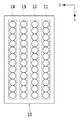
図3は、上記4つの記録ヘッド4a〜4dのうち、記録ヘッド4aを構成するチップ10の、ノズル(吐出口)の配列状態を示す図である。本実施例において、チップ10上には4列のノズル列11〜14がX方向に並列しており、個々のノズル列は同じ種類のインクを吐出するノズルがY方向に600dpiピッチで複数配列している。各ノズルは、吐出エネルギ発生素子と吐出口とから構成される。インクの吐出方式については、発熱素子を用いた方式、ピエゾ素子を用いた方式、静電素子を用いた方式、およびMicro Electro Mechanical Systems(MEMS)素子を用いた方式等を採用することができる。本実施形態では、このようなチップ10が、X方向に交互にずれながらY方向に複数配列することにより、記録媒体3のY方向の幅が600dpiピッチで配列するノズルで覆われるような記録ヘッド4aが画成されている。
FIG. 3 is a diagram illustrating an arrangement state of nozzles (ejection ports) of the
このような構成のもと、X方向に搬送される記録媒体において、X方向に延びる1ラインのドット列は、ノズル列11〜14のいずれかのノズルすなわち4つのノズルによって代わる代わる記録される。そして、いずれかのノズルが吐出不良と検出された場合には、他の3つのノズルによって補完しながら、記録を行う。
With such a configuration, on the recording medium transported in the X direction, one line of dot rows extending in the X direction is recorded in place of any of the nozzles in the
なお、記録ヘッドについては、このような複数のチップをつなぎ合わせて構成されるものでなくても構わない。記録ヘッドが、記録媒体3のY方向の幅全域に渡ってノズルが一列に配列された1つのチップによって構成された記録ヘッドであっても構わない。また、ここでは、KCMYの4色のインクに対応した記録ヘッド4a〜4dを配備した構成としているが、インクの色数および記録ヘッドの個数はこれに限定されるものではない。
The recording head does not have to be configured by connecting a plurality of such chips. The recording head may be a recording head constituted by one chip in which nozzles are arranged in a line over the entire width of the
図4は、記録装置1の制御部14の構成を示すブロック図である。制御部14は、主に、ホスト装置16とデータの授受を行うための外部インターフェイス205、記録装置全体を制御するためのコントローラ17、およびユーザインターフェースとなる操作部15とを備えている。更に、コントローラ17は、CPU201、ROM202、RAM203、HDD204、画像処理部207、エンジン制御部208、ヘッドドライバ209、スキャナドライバ211を備えている。
FIG. 4 is a block diagram illustrating a configuration of the
CPU201は、ROM202に格納されたプログラムに従い、RAM203をワークエリアとしながら、各種処理を実行する。この際、HDD204は、記録データ、および記録装置1の各種動作に必要な設定情報を記憶する領域として使用される。また、画像処理部207は、CPU201の制御の下、ホスト装置16から受信した画像データの画像処理を行って、記録ヘッド4a〜4dが記録可能な記録データを生成し、RAM203またはHDD204に格納する。CPU201は、このように格納された記録データに従って、ヘッドドライバ209を制御し、記録ヘッド4a〜4dからインクを吐出させる。この際、CPU201は、エンジン制御部208介して、給紙部2、検査部6、切断部8、および搬送機構13等を制御する。また、スキャナドライバ211を介してスキャナ7aおよび7bを駆動する。
The
操作部15は、ユーザとの入出力インターフェイスであり、入力部、および出力部から構成されている。入力部はハードキーやタッチパネル等で構成され、ユーザからの指示を受信するものである。出力部はディスプレイや音声発生装置などであり、情報を表示または発して、ユーザに対して情報を伝達するものである。
The
なお、ホスト装置16は、コンピュータ等の汎用の機器であってもよいし、画像読み取り部を有する画像キャプチャ、デジタルカメラ、およびフォトストレージ等の画像専用の機器であってもよい。ホスト装置16がコンピュータである場合、コンピュータ内の記憶装置には、オペレーションシステム、アプリケーションソフトウェア、および記録装置1用のプリンタドライバがインストールされていることが望まれる。
The host device 16 may be a general-purpose device such as a computer, or may be an image-dedicated device such as an image capture having an image reading unit, a digital camera, and a photo storage. When the host device 16 is a computer, it is desirable that an operating system, application software, and a printer driver for the
(特徴構成)
以下、本実施形態における特徴的な構成について説明する。なお、以下の説明において、記載の混同を避けるため、ノズルの吐出状態を検出するために記録する画像データを検査画像、当該検査画像に従って記録媒体に記録したものを検査パターンとする。同様に、写真など、印刷の目的となる画像のデータを実画像、当該実画像に従って記録媒体に記録したものを実画と称する。本実施形態においては、1つの記録開始コマンドによって、連続紙である記録媒体に対し、複数の実画像を連続記録する場合について説明する。
(Feature configuration)
Hereinafter, a characteristic configuration in the present embodiment will be described. In the following description, in order to avoid confusion, the image data to be recorded for detecting the ejection state of the nozzle is referred to as an inspection image, and the data recorded on the recording medium according to the inspection image is referred to as an inspection pattern. Similarly, data of an image to be printed, such as a photograph, is called a real image, and data recorded on a recording medium according to the real image is called a real image. In the present embodiment, a case will be described in which a plurality of real images are continuously recorded on a recording medium that is continuous paper by one recording start command.
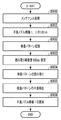
図5は、記録装置1に対しホスト装置16あるいは操作部15を介してユーザから記録開始コマンドが入力された場合にCPU201が実行するシーケンスを示すフローチャートである。
FIG. 5 is a flowchart illustrating a sequence executed by the
本処理が開始されると、CPU201は、まずステップS501において、第1検出処理を実行し、その後ホスト装置16から実画像を受信する(ステップS502)。
When this process is started, the
図6は、ステップS501で実行する第1検出処理シーケンスを説明するためのフローチャートである。本処理が開始されると、CPU201は、まず、ステップS800にて、記録ヘッドのメンテナンス処理を実行する。ここで行うメンテナンス処理は、比較的大掛かりな吸引回復処理、画像の記録にインクを吐出する予備吐出処理および記録ヘッドの吐出口面をワイパーでワイピングするワイピング処理などのうち少なくとも1つである。このメンテナンス処理を実行することにより、ヒータ断線のような半永久的な原因を有さないノズルについては、殆ど吐出状態を正常化することが出来る。
FIG. 6 is a flowchart for explaining the first detection processing sequence executed in step S501. When this process is started, the
続くステップS801において、CPU201は、HDD204に記憶されている第1検出不良ノズル情報と、第2検出不良ノズル情報をリセット(クリア)する。本実施形態において、第1検出不良ノズル情報と、第2検出不良ノズル情報は、HDD204の異なる領域に格納されており、ステップS801では、これら両方の情報をリセット、すなわち吐出不良ノズルが存在しない状態にメモリをクリアする。但し、出荷時において、既に吐出不良のノズル情報が検出されている場合には、出荷時の情報に戻すようなリセットであっても構わない。
In subsequent step S <b> 801, the
ここで、第1検出不良ノズル情報とは、第1検出処理にて不良ノズルとして検出されたノズルに関する情報であり、記録ヘッドおよび記録ヘッドにおける不良ノズルの位置が1ノズル単位で特定できる情報となっている。すなわち、この第1検出不良ノズル情報は、ステップS800のメンテナンス処理を行っても回復できなかったノズルに関する情報であり、このノズルは、今後メンテナンス処理を行っても回復できない可能性が高いことを示している。このため、後述のステップS509においてメンテナンス処理を行った後、ステップS510において吐出不良ノズル情報を更新するタイミングにおいて、この第1検出不良ノズル情報はリセットせずに吐出不良ノズルとして記憶しておく。また、後のステップS504において画像データを各ノズルに振り分ける際に、この第1検出処理において吐出不良ノズルとして検出されたノズルには画像データは振り分けず、他のノズルに振り分けることによって補完記録が行われる。 Here, the first detection failure nozzle information is information related to the nozzle detected as a failure nozzle in the first detection process, and is information that can specify the position of the failure nozzle in the recording head and the recording head in units of one nozzle. ing. That is, this first detection failure nozzle information is information relating to a nozzle that could not be recovered even after performing the maintenance process in step S800, and indicates that this nozzle is likely not to be recovered even if a maintenance process is performed in the future. ing. For this reason, after performing a maintenance process in step S509, which will be described later, at the timing of updating the ejection failure nozzle information in step S510, the first detection failure nozzle information is stored as a ejection failure nozzle without being reset. In addition, when image data is allocated to each nozzle in the subsequent step S504, the image data is not allocated to the nozzles detected as ejection failure nozzles in the first detection process, and complementary recording is performed by distributing to other nozzles. Is called.
一方、第2検出不良ノズル情報とは、ステップS507で実行する第2検出処理にて不良ノズルとして検出されたノズルに関する情報である。前述の第1検出処理において検出されたノズルは、ステップS504において他のノズルによって補完記録が行われるように処理されるため、この第2検出処理において検出された不良ノズルは、画像記録中に発生した不良ノズルである。この不良ノズルの発生原因については図14を用いて後に詳しく説明する。そして、この画像記録中に発生した不良ノズルは、メンテナンス処理を行うことによって回復するノズルであると考えられる。このため、ステップS800及びS509においてメンテナンス処理が行われると、ステップS801及びS510においてこの第2検出不良ノズル情報がリセットされる。 On the other hand, the second detection failure nozzle information is information relating to the nozzle detected as a failure nozzle in the second detection process executed in step S507. Since the nozzles detected in the first detection process described above are processed so that complementary recording is performed by other nozzles in step S504, defective nozzles detected in the second detection process occur during image recording. This is a defective nozzle. The cause of the defective nozzle will be described later in detail with reference to FIG. The defective nozzle generated during the image recording is considered to be a nozzle that is recovered by performing the maintenance process. For this reason, when the maintenance process is performed in steps S800 and S509, the second detection failure nozzle information is reset in steps S801 and S510.
次に、ステップS802において、CPU201は記録ヘッド4a〜4dを用い、予めROM202に格納されている検査画像に従って、記録媒体に対し不吐出ノズル検出用の検査パターンを記録する。その後、ステップS803において、検出パターンを読み取り部6で読み取る際の解像度を記録解像度と等しい600dpiに設定した後、更にステップS804にて、スキャナ7aを用いて検査パターンの読み取りを行う。
Next, in step S <b> 802, the
図7(a)および(b)は、第1検出処理における、検出パターンのドット配列状態と読み取り部7が読み取った結果を示す図である。図3を参照しながら説明するに、本実施形態の検査画像は、1つのノズル列に含まれる全てのノズルが4ドットずつX方向に連続して記録し、そのような4ドット連続パターンを、4つのノズル列11〜14が順番に記録するようになっている。図7(a)において、101がノズル列11によって記録されたパターン、102がノズル列12によって記録されたパターン、103がノズル列13によって記録されたパターン、104がノズル列14によって記録されたパターンである。ここでは、ノズル列14の4番目のノズルが吐出不良であった場合を示しており、当該ノズルが記録するべき箇所が白スジ901となって確認できる。なお、記録ヘッドは、白スジを検出した位置がどのノズル列のどのノズルに相当するかを判断するための基準パターン902も検出パターンの一部に記録している。
7A and 7B are diagrams showing the dot arrangement state of the detection pattern and the result read by the
図7(b)において、301がパターン101を読み取った結果の画像データ、302がパターン102を読み取った結果の画像データ、303がパターン103を読み取った結果の画像データ、304がパターン104を読み取った結果の画像データである。ここでは、記録ヘッドの記録解像度とスキャナの読み取り解像度が同じ600dpiであるので、ドットが記録されている画素の1つ1つが黒(1)と検出される中、画像データ304の4画素目のみが白(0)と検出されている。
In FIG. 7B, 301 is image data obtained by reading the
ステップS805において、CPU201は、白データが確認された位置903と基準パターンを検出した位置904とから吐出不良ノズルの位置を判断し、当該情報を第1検出不良ノズル情報としてHDD204に記憶する(ステップS806)。図7(b)の場合であれば、ノズル列14の4番目のノズルが吐出不良である旨が、HDD204の第1検出不良ノズル情報の領域に記憶される。
In step S805, the
なお、図ではドットが記録されている画素が黒(1)、記録されていない画素が白(0)と判別される場合で説明したが、実際にスキャナが取得する画像データは多値の輝度情報であり、白か黒かを簡単に判断できるものではない。よって、ステップS805においては、X方向に読み取り輝度値の移動平均を取り、Y方向に対してヒストグラム解析することによって、吐出不良ノズルの判定処理を行ってもよい。 In the figure, the pixel in which dots are recorded is described as black (1), and the pixel in which dots are not recorded is determined to be white (0). However, the image data actually acquired by the scanner is multivalued luminance. It is information and cannot be easily judged whether it is white or black. Therefore, in step S805, the defective discharge nozzle determination process may be performed by taking a moving average of the read luminance values in the X direction and performing a histogram analysis in the Y direction.
以上で第1検出処理が終了し、図5のステップS502に進む。この第1検出処理は、メンテナンスジョブとして実行され、処理終了後に検査パターンを切断し、未使用のロール紙が巻き戻される。 Thus, the first detection process ends, and the process proceeds to step S502 in FIG. This first detection process is executed as a maintenance job. After the process is completed, the inspection pattern is cut, and unused roll paper is rewound.
ステップS502において、CPU201は、通常印刷ジョブとして記録媒体3に記録すべき実画像データをホスト装置から受信して、RAM203に記憶する。本実施形態において、ホスト装置16から受信する実画像は、300dpiのRGBデータとする。
In step S <b> 502, the
ステップS503において、CPU201は画像処理部207を用い、実画像の300dpiのRGB多値データから、記録ヘッドが記録可能な600dpiのCMYK2値データを生成する。
In step S503, the
図8は、画像処理部207が実行する実画像に対する画像処理工程を説明するためのフローチャートである。本処理が開始されると、画像処理部207は、まずステップS141にて、色処理Aを実行する。色処理Aは、ホスト装置16で表現された色空間を、記録装置1で表現可能な色空間に適応させるための処理であり、300dpiの多値のRGBデータが同じく300dpiの多値のR´G´B´データに変換される。
FIG. 8 is a flowchart for explaining an image processing process for an actual image executed by the
続くステップS142において、画像処理部207は、色処理Bを実行する。色処理Bは、輝度データであるRGBデータを記録装置1で使用するインク色に対応した濃度データCMYKに変換するための処理である。具体的には、ROM202に予め格納されている3次元のルックアップテーブルを参照することにより、R´G´B´の多値データをC1、M1、Y1、K1の多値データに変換する。
In subsequent step S142, the
ステップS143では、1次元のルックアップテーブルを用い、多値データC1、M1、Y1、K1を、多値データのC2、M2、Y2、K2に変換する。ここで行うγ補正は、入力濃度信号C1、M1、Y1、K1に対し記録媒体上で実際に表現される濃度が、線形関係を得られるようにするための補正である。 In step S143, the multi-value data C1, M1, Y1, and K1 are converted into multi-value data C2, M2, Y2, and K2, using a one-dimensional lookup table. The γ correction performed here is correction for obtaining a linear relationship between the densities actually expressed on the recording medium with respect to the input density signals C1, M1, Y1, and K1.
さらに、ステップS144では、量子化処理を行い、300dpiの多値データのC2、M2、Y2、K2を、記録(1)または非記録(0)を示す600dpiの2値データC3、M3、Y3、K3に変換する。量子化の方法としては、誤差拡散法やディザ法を用いることが出来る。量子化後の2値の記録データは、ラスタ(X方向に連続する列)ごとにRAM203に記憶される。以上で、画像処理部207における画像処理が終了し、個々のノズルが記録可能な記録データC3、M3、Y3、K3が得られ、図5のステップS504に進む。
Further, in step S144, quantization processing is performed, and 300 dpi multi-value data C2, M2, Y2, and K2 are converted into 600 dpi binary data C3, M3, Y3, indicating recording (1) or non-recording (0), Convert to K3. As a quantization method, an error diffusion method or a dither method can be used. The binary recording data after quantization is stored in the
ステップS504では、RAM203に記憶された2値の記録データを、図6のステップS806で記憶した第1検出不良ノズル情報および後述する第2件出不良ノズル情報に従って、個々のノズルに振り分ける。この場合、吐出不良ノズルを含まないラスタについては、全てのノズル列11〜14に均等に記録データ(1)を振り分ける。一方、吐出不良ノズルを含むラスタについては、ノズル列11〜14のうち吐出が正常なノズル列にのみデータを振り分ける。図7(b)のような場合には、4番目のラスタにおいて、ノズル列11、12および13にのみ記録データ(1)を振り分け、ノズル列14には振り分けない。
In step S504, the binary recording data stored in the
ステップS505において、CPU201は記録ヘッド4a〜4dを用い、ステップS504で振り分けた記録データに従って1ページ分の記録を実行する。この際、ステップS501の第1検出処理にて吐出不良であると検出されたノズルが記録すべきデータは、他のノズルに振り分けられているので、白スジのない画像を出力することが出来る。
In step S505, the
続くステップS506において、CPU201は、記録部5が所定数のページの記録を行ったか否かを判断する。所定ページ数にまだ達していないと判断した場合は、ステップS511にて、実画像の全ての記録が完了したか否かを判断し、完了していなければ次ページの印刷のためにステップS502に戻る。また、完了している場合は本処理を終了する。一方、ステップS506で、所定ページ数に達したと判断した場合はステップS507に進み、第2検出処理を実行する。
In subsequent step S506,
ここで所定ページ数とは、第2検出処理を実行する間隔を規定するページ数であり、突発的な吐出不良が多数現れない程度のページ数であることが望まれる。このようなページ数は、記録状況などによって適宜設定可能な値であり、また、ユーザによって設定可能とすることも出来る。更に、第2検出処理の検査パターンを挿入する間隔は、画像のページ数(枚数)で決めなくてもよい。例えば、搬送方向の長さが所定の長さを超えるタイミングや、所定時間経過したタイミングにおいて検査パターンを挿入する形態であってもよい。 Here, the predetermined number of pages is the number of pages that defines the interval at which the second detection process is performed, and is desirably a number of pages that does not cause many sudden ejection failures. The number of pages is a value that can be set as appropriate depending on the recording status, and can also be set by the user. Further, the interval for inserting the inspection pattern of the second detection process may not be determined by the number of pages (number of pages) of the image. For example, the inspection pattern may be inserted at a timing when the length in the transport direction exceeds a predetermined length or when a predetermined time has elapsed.
図9は、ステップS507で実行する第2検出処理シーケンスを説明するためのフローチャートである。本処理が開始されると、CPU201は、まずステップS1001にて、第1検出処理と同様の検査画像に従って、不吐出ノズル検出用の検査パターンを記録する。連続記録中に行われる第2検出処理は、その処理自体を短時間で完了させる必要があるため、第1検出処理のように記録ヘッドのメンテナンス処理などを行うことなく、直ぐに検査パターンの記録を開始する。
FIG. 9 is a flowchart for explaining the second detection processing sequence executed in step S507. When this process is started, the
図10(a)および(b)は、連続紙である記録媒体3に、実画像と検査パターンが連続して記録される状態の例を示した図である。図において、検査パターンAが第1検出処理にて記録される検査パターン、検査パターンBが第2検出処理にて記録される検査パターンである。実画1、2、3は、1つの実画像に対するステップS502〜S503の工程を、3回繰り返すことによって記録される3つの実画である。この実画1、2、3は、検査パターンBの記録が完了すると、滞ることなく次の実画が連続的に記録される。このように、本実施形態において、第2検出処理による検査パターンは、実画と実画の間に時間的にも位置的にも無駄のない状態で記録されている。
FIGS. 10A and 10B are diagrams illustrating an example of a state where an actual image and an inspection pattern are continuously recorded on the
また、図10(b)のように、最初の実画1の前と最後の実画Eの後に検査パターンBを挿入することによって第2検出処理を行えば、画像記録の開始時及び終了時に吐出不良のない状態を保つことができる。
Further, as shown in FIG. 10B, when the second detection process is performed by inserting the inspection pattern B before the first
なお、第1検出処理において用いる検査パターンは、図7に示したパターンに限るものではなく、第2検出処理における検査パターンよりも高精度に吐出不良ノズルを検出可能な検査パターンであればどのようなものであってもよい。例えば、図15に示すように、ノズル111で記録するラインL111とノズル112で記録するラインL112がX方向にオフセットして記録された階段状パターンであってもよい。このような検査パターンであれば、1ノズル単位で記録を行い、隣接ノズルの影響を受けることなく1ノズル単位で吐出不良を検出することができる。図7の検査パターンでは、吐出されたインク滴がY方向にヨレて着弾した場合に、Y方向のノズル間隔が狭いと、インク滴が吐出されているにも関わらず吐出不良ノズルであると誤検出してしまう場合がある。これに対し図15のような階段状パターンを用いることで、吐出不良の誤検出を低減し、不良ノズル検出精度を上げることができる。
Note that the test pattern used in the first detection process is not limited to the pattern shown in FIG. 7, and any test pattern that can detect ejection failure nozzles with higher accuracy than the test pattern in the second detection process is used. It may be anything. For example, as shown in FIG. 15, the line L111 recorded by the
図9のフローチャートに戻る。ステップS1001にて検査パターンが記録されると、CPU201はステップS1002に進み、当該検出パターンの読み取り解像度を300dpiに設定する。この300dpiという値は、記録解像度や第1検出処理での読み取り解像度600dpiの半分に相当する。その後、ステップS1003に進み、スキャナ7aを用いて検査パターンの読み取りを行う。
Returning to the flowchart of FIG. When the inspection pattern is recorded in step S1001, the
図11(a)および(b)は、第2検出処理において、検出パターンにおけるドット配列状態と読み取り部7が読み取った結果を示す図である。第2検出処理で記録する検査パターンも、第1検出処理で記録する検査パターンと等しく、全てのノズルが4ドットずつ連続記録するパターンを、4つのノズル列11〜14で順番に記録するようになっている。
FIGS. 11A and 11B are diagrams showing the dot arrangement state in the detection pattern and the result read by the
ここで、第1検出処理において吐出不良と判断されたノズル列14の4番目のノズルが記録すべき4つのドットは、ノズル列11、12および13夫々の4番目のノズルによって記録されているので、図7(a)で示した白スジ901は現れていない。但し、実画を3ページ分記録した後の第2検査パターンでは、ノズル列12の6番目のノズルが吐出不良となり、当該ノズルが記録すべき位置が白スジ1101となっている。
Here, the four dots to be recorded by the fourth nozzle of the
図12(a)〜(c)は、第2検出処理における、記録解像度と読み取り解像度の関係を示した図である。ここでは、記録ヘッドの記録解像度600dpiに対し、スキャナの読み取り解像度がその半分の300dpiであるので、読み取り解像度の1画素領域は、記録解像度の2画素×2画素領域に相当する。 12A to 12C are diagrams illustrating the relationship between the recording resolution and the reading resolution in the second detection process. Here, since the reading resolution of the scanner is 300 dpi, which is half that of the recording resolution of the recording head of 600 dpi, one pixel area of the reading resolution corresponds to a 2 pixel × 2 pixel area of the recording resolution.
ここで、図12(a)のように、600dpiの2画素×2画素領域のうち3つの画素にドットが記録され、1つの画素には記録されていない場合を考える。このように記録された画像を、600dpiの解像度で読み取った場合、読み取りデータは図12(b)のようになる。すなわち、ドットが記録された画素の読み取り値が黒(1)、ドットが記録されていない画素の読み取り値は白(0)となり、記録の事実と同じ結果を得ることが出来る。
Here, as shown in FIG. 12A, a case is considered in which dots are recorded in three pixels of a 600
これに対し、図12(a)のように記録された画像を、300dpiの解像度で読み取った場合、読み取りデータは図12(c)のようになる。すなわち、4つのドットが記録可能な領域に3つのドットが記録されている領域全体の濃度を読み取ることになるので、ドットの有無を平均化した結果が得られることになる。詳しくは、300dpiの1画素領域にドットが記録されていない領域が含まれているという事実は得られるが、どの位置にドットが記録されていないかを限定することが出来ない。 On the other hand, when an image recorded as shown in FIG. 12A is read at a resolution of 300 dpi, the read data is as shown in FIG. That is, since the density of the entire area where three dots are recorded is read in an area where four dots can be recorded, the result of averaging the presence or absence of dots is obtained. Specifically, although it is possible to obtain the fact that an area in which dots are not recorded is included in one pixel area of 300 dpi, it is not possible to limit where the dots are not recorded.
以上のような読み取り処理を行うことにより、図11(a)で示した検査パターンを読み取った結果は図11(b)のようになる。低い濃度が検出された位置1102には、白スジ1101が含まれると判断することができる。
By performing the reading process as described above, the result of reading the inspection pattern shown in FIG. 11A is as shown in FIG. It can be determined that the
その後、ステップS1004において、CPU201は、検出濃度の低い画素が確認された位置1102と基準パターンを検出した位置1103とから吐出不良ノズルの位置を判断する。図11(b)の場合であれば、白スジ1101が含まれる領域は、低濃度が確認された領域1102に含まれること、つまりノズル列12の5番目および6番目の何れかあるいは両方に吐出不良のノズルが存在すると判断する。
Thereafter, in step S1004, the
但し、ドットの記録位置によって規定される600dpiの2×2画素領域と、スキャナが読み取る300dpiの1画素領域は、紙面上で必ずしも一致しているとは限らない。よって、本実施形態では、続くステップS1005において、吐出不良のノズルとして設定する範囲を、ステップS1004で判断した2ノズルを中心に拡張する。具体的には、ノズル列12の3〜8番目のノズルを吐出不良ノズルとする(図11(b)参照)。このような拡張処理を行うことによって、実際に吐出不良となっているノズルの記録が吐出不良と判断されず、他のノズルによって補完できないような状況を回避することが出来る。
However, the 600
その後、ステップS1006に進み、ノズル列12の3〜8番目のノズルが吐出不良ノズルである旨を、HDD204の第2検出不良ノズル情報の領域に記憶する。
Thereafter, the process proceeds to step S1006, and the fact that the 3rd to 8th nozzles in the
しかしながら、600dpiの2×2画素領域と、スキャナが読み取る300dpiの1画素領域との間で殆どずれが発生しないことが分かっている場合には、ステップS1005のような工程は必ずしも必要ない。この場合には、ステップS1004からステップS1006へ進み、ノズル列12の5番目および6番目の2ノズルが吐出不良である旨をHDD204の第2検出不良ノズル情報の領域に記憶すればよい。
以上で本処理を終了し、図5のステップS508に進む。
However, if it is known that there is almost no deviation between the 600
Thus, the present process is terminated, and the process proceeds to step S508 in FIG.
以上説明した第2検出処理は、第1検出処理に比べて、上述した様に吐出不良ノズルの検出精度は劣る。そして、個々のノズルについてではなく、ノズル群の単位吐出不良か否かが判断されるので、実際には吐出不良ではないノズルも、吐出不良と判断されて記録するべき実画像を記録しない状況が生じる。しかしながら、第2検出処理は、その解像度を半分に低減している分、画像処理の対象となる画素数が減って処理を高速に完了させ、迅速に次の実画像の記録に移行することが出来る。 As described above, the second detection process described above is inferior in detection accuracy for defective ejection nozzles as compared to the first detection process. Then, since it is determined whether or not the unit discharge failure of the nozzle group, not for each individual nozzle, there is a situation in which a nozzle that is not actually a discharge failure is determined to be a discharge failure and does not record an actual image to be recorded. Arise. However, in the second detection process, since the resolution is reduced by half, the number of pixels to be subjected to image processing is reduced, the process is completed at high speed, and the next real image can be quickly recorded. I can do it.
ステップS508では、第2検出処理において吐出不良と判断されたノズルが所定数を超えたか否かを判断する。吐出不良のノズルが所定数を超えていない場合はステップS511へ進み、所定数を超えている場合は、吐出不良のノズルのための不吐補完は限界であると判断し、ステップS509へ進む。 In step S508, it is determined whether or not the number of nozzles determined to be defective in the second detection process exceeds a predetermined number. If the number of defective nozzles does not exceed the predetermined number, the process proceeds to step S511. If the predetermined number is exceeded, it is determined that non-discharge complementation for the defective nozzles is a limit, and the process proceeds to step S509.
図13(a)および(b)は、ステップS508において、吐出不良と判断されたノズルのカウント方法を説明するための図である。ステップS508の工程は、「吐出不良のノズルの記録データを補完することが出来る正常なノズルが十分に存在するか」を判断するための工程である。よって、その判断は、吐出不良ノズルの記録データをどのノズルで補完するかによって異なる。 FIGS. 13A and 13B are diagrams for explaining a method of counting nozzles determined to be defective in step S508. The process of step S508 is a process for determining whether “there are sufficient normal nozzles capable of complementing the recording data of the nozzles with defective ejection”. Therefore, the determination differs depending on which nozzle is used to supplement the recording data of the ejection failure nozzle.
ここで、図13(a)は、吐出不良のノズルの記録位置を、本実施形態の様に、同じラスタデータを記録する別のノズル列のノズルによって補完する場合について示している。ここでは、同じラスタデータを記録する4つのノズルの中で、吐出不良のノズル数をカウントする。全ラスタについて上記カウントを行い、カウント値が閾値(例えば3)以上のラスタが1つでも存在した場合に、不吐補完は不能であると判断し、ステップS509へ進む。 Here, FIG. 13A shows a case where the recording positions of the nozzles with defective ejection are complemented by the nozzles of another nozzle row that records the same raster data as in this embodiment. Here, among the four nozzles that record the same raster data, the number of defective nozzles is counted. The above-mentioned count is performed for all rasters, and if there is at least one raster whose count value is greater than or equal to a threshold value (for example, 3), it is determined that non-discharge complementation is impossible, and the process proceeds to step S509.
一方、図13(b)は、吐出不良ノズルの記録位置を同じノズル列の両側のノズルによって補完する場合のカウント方法を示している。ここでは、連続する8ノズルのエリア中に含まれる吐出不良ノズルの数を、エリアを1ノズルずつずらしながら、カウントする。カウント値が閾値(例えば7)以上のエリアが1つでも存在した場合に、不吐補完は不能であると判断しステップS509へ進む。 On the other hand, FIG. 13B shows a counting method in a case where the recording positions of defective ejection nozzles are complemented by nozzles on both sides of the same nozzle row. Here, the number of ejection failure nozzles included in the continuous 8-nozzle area is counted while shifting the area by one nozzle. If there is even one area whose count value is equal to or greater than a threshold value (for example, 7), it is determined that non-discharge complementation is impossible and the process proceeds to step S509.
ステップS509では、記録ヘッドに対するメンテナンス処理を実行する。ここで実行するメンテナンス処理は、第1検出処理のステップS800で実行するメンテナンスシーケンスと同等であり、半永久的な原因を有する以外の吐出不良、すなわち、第2検出処理にて検出された吐出不良については、殆ど回復することが出来る。 In step S509, maintenance processing for the print head is executed. The maintenance process executed here is equivalent to the maintenance sequence executed in step S800 of the first detection process, and the discharge failure other than having a semi-permanent cause, that is, the discharge failure detected in the second detection process. Can almost recover.
図14(a)および(b)は、第2検出処理にて新たに検出される吐出不良ノズルの様子を説明する図である。第2検出処理にて新たに検出される吐出不良は、メンテナンス処理を伴わない連続記録によって発生する吐出不良であり、主に、吐出口の表面外からの紙片やノズル内の泡によって引き起こされる。例えば、図14(a)は、正常な吐出が行われていたが、吐出口に紙片等の異物が詰まり吐出口を完全に閉塞してしまった場合を示している。この場合、そのまま吐出動作を継続しても、閉塞されたノズルからはインクが吐出されないままである。一方、図14(b)は、正常な吐出が行われていたが、吐出口の一部に紙片等の異物が詰まり、吐出口を半分閉塞してしまった場合を示している。この場合は、吐出動作を継続すると、半分閉塞された吐出口からにじみ出たインクが異物の周りに固着し、徐々に成長し、隣接するノズルの吐出口まで閉塞してしまう。 FIGS. 14A and 14B are diagrams illustrating the state of a defective ejection nozzle newly detected in the second detection process. The discharge failure newly detected in the second detection process is a discharge failure that occurs due to continuous recording without a maintenance process, and is mainly caused by a piece of paper from outside the surface of the discharge port or bubbles in the nozzle. For example, FIG. 14A shows a case where normal ejection has been performed, but the ejection port is completely blocked by a foreign object such as a piece of paper clogging the ejection port. In this case, even if the ejection operation is continued as it is, ink is not ejected from the blocked nozzle. On the other hand, FIG. 14B shows a case where normal ejection was performed, but a foreign matter such as a piece of paper was clogged in a part of the ejection port, and the ejection port was half blocked. In this case, if the ejection operation is continued, the ink oozed from the half-occluded ejection port adheres around the foreign matter, grows gradually, and clogs to the ejection port of the adjacent nozzle.
そして、メンテナンス処理を実行せずに実画像の記録を継続すると、図14(a)や(b)のような吐出不良の数は、徐々に増大していく。但し、吸引回復処理、吐出口面に対するワイピング処理、予備吐出処理等の一連のメンテナンス処理を実行すれば、このような異物や固着したインクは比較的簡単に除去される。すなわち、第2検出処理にて新たに検出される吐出不良は、ステップS509によるメンテナンス処理を周期的に行えば、ほぼ完璧に回復するころが出来る。 If the recording of the actual image is continued without executing the maintenance process, the number of ejection defects as shown in FIGS. 14A and 14B gradually increases. However, if a series of maintenance processes such as a suction recovery process, a wiping process for the ejection port surface, and a preliminary ejection process are executed, such foreign matter and adhered ink can be removed relatively easily. That is, the ejection failure newly detected in the second detection process can be almost completely recovered by performing the maintenance process in step S509 periodically.
その後、ステップS510に進み、CPU201は、HDD204に記憶されている第2検出不良ノズル情報をリセットして、ステップS511へ進む。このとき、第1検出情報はリセットせずに、吐出不良ノズル情報として残す。
Thereafter, the process proceeds to step S510, where the
ステップS511では、実画像の全ての記録が完了したか否かを判断し、完了していなければ次ページの印刷のためにステップS502に戻る。また、完了している場合は本処理を終了する。 In step S511, it is determined whether or not all recording of the actual image has been completed. If not, the process returns to step S502 to print the next page. Further, if it has been completed, this processing is terminated.
以上説明したように、本実施形態によれば、精度の高い状態で吐出不良ノズルを検出する第1の検出処理と、精度は低いが吐出不良ノズルを高速に検出可能な第2の検出処理とを用意する。そして、連続記録中でない場合には、メンテナンス処理を伴いながら第1検出処理を実行し、連続記録中においてはメンテナンス処理を伴わずに所定のタイミングで第2検出処理を実行する。但し、第2検出処理で検出された吐出不良ノズルの数が所定値以上になってしまった場合には、メンテナンス処理を実行し、第2検出処理によって検出された吐出不良ノズルの情報のみをリセットする。 As described above, according to the present embodiment, the first detection process for detecting a defective discharge nozzle in a highly accurate state, and the second detection process for detecting a defective discharge nozzle at a high speed with a low accuracy. Prepare. When the continuous recording is not being performed, the first detection process is performed with the maintenance process, and during the continuous recording, the second detection process is performed at a predetermined timing without the maintenance process. However, if the number of defective ejection nozzles detected in the second detection process exceeds a predetermined value, the maintenance process is executed and only the information on the defective ejection nozzles detected in the second detection process is reset. To do.
このような本実施形態によれば、連続記録中においてもメンテナンス処理などによって記録動作を中断することなく、迅速に吐出不良ノズルを検出してこれを補完することが可能となる。そして、適切なタイミングで必要最低限のメンテナンス処理を実行しながらも、メンテナンス処理によって回復不可能な吐出不良ノズルについては、その情報を維持し、その記録位置に対する補完を継続することができる。 According to the present embodiment as described above, it is possible to quickly detect a defective ejection nozzle and complement it without interrupting the recording operation by a maintenance process or the like even during continuous recording. Then, while executing the minimum necessary maintenance process at an appropriate timing, it is possible to maintain the information about the ejection failure nozzles that cannot be recovered by the maintenance process, and continue the supplement to the recording position.
なお、以上では、記録解像度を600dpiとし、第1検出処理で読み取るための第1の解像度を600dpi、第2検出処理での読み取るための第2の解像度を300dpiとしたが、本発明はこのような解像度に限定されるものではない。例えば、第1の解像度は、記録解像度よりも高い解像度とすることも出来る。この場合、第1検出処理における検出精度は、上記実施形態よりも更に向上させることが出来る。また、第2解像度は、記録解像度の半分の解像度でなくてもよく、高速処理に影響を与えない程度の処理負荷であれば、記録解像度と等しい解像度であっても構わない。逆に、記録解像度の半分程度であっても処理の負荷が大きい場合には、更に低い解像度としてもよい。更に、吐出不良のノズル位置を検出するのに影響するのは、ノズル並び方向すなわちY方向の解像度であるので、記録媒体搬送方向(X方向)の解像度は特に指定されるものではない。 In the above description, the recording resolution is set to 600 dpi, the first resolution for reading in the first detection process is set to 600 dpi, and the second resolution for reading in the second detection process is set to 300 dpi. The resolution is not limited. For example, the first resolution can be higher than the recording resolution. In this case, the detection accuracy in the first detection process can be further improved as compared with the above embodiment. The second resolution may not be half the recording resolution, and may be the same resolution as the recording resolution as long as the processing load does not affect the high-speed processing. On the other hand, even if the recording resolution is about half, if the processing load is large, a lower resolution may be used. Further, since it is the resolution in the nozzle arrangement direction, that is, the Y direction, which affects the detection of the nozzle position of ejection failure, the resolution in the recording medium conveyance direction (X direction) is not particularly specified.
また、以上では、記録装置が記録コマンドを受信したタイミング、すなわち記録動作開始直前に第1検出処理を実行する内容で説明したが、第1検出処理を実行するタイミングはこれに限定されるものではない。第1検出処理は、記録動作を中断しなければ、装置の電源をONした時等、どのようなタイミングで実行しても構わない。例えば、ユーザが操作部15から指定したタイミングで実行するようにしてもよい。
In the above description, the timing at which the recording apparatus receives the recording command, that is, the content of executing the first detection process immediately before the start of the recording operation has been described. However, the timing of executing the first detection process is not limited to this. Absent. The first detection process may be executed at any timing such as when the apparatus is turned on as long as the recording operation is not interrupted. For example, it may be executed at a timing designated by the user from the
また、上記実施形態では、ステップS506において、記録部5が所定数のページの記録を行ったか否かによって、第2検出処理の実行タイミングを判断したが、本発明はこのような形態に限定されるものではない。ステップS506では、吐出不良が発生しうるレベルまで記録動作が継続されたかどうかが判断されれば良く、その判断基準は、ページ数でなくても構わない。様々なサイズの実画像を連続して記録するような場合には、ページ数のほか実画像のサイズも考慮に入れて判断しても良く、更に、記録動作継続時間、前回メンテナンス処理を実行してからの経過時間、搬送距離、吐出回数値などを基準に判断することも出来る。
In the above embodiment, in step S506, the execution timing of the second detection process is determined based on whether or not the
また、上記実施形態では、第1検出処理と第2検出処理とで、同じ検査画像を用いたが、精度重視の第1検出処理と処理時間重視の第2検査シーケンスでは、異なる検査画像に基づいて異なる検査パターンを記録することも有効である。 In the above embodiment, the same inspection image is used in the first detection process and the second detection process. However, the first detection process emphasizing accuracy and the second inspection sequence emphasizing processing time are based on different inspection images. It is also effective to record different inspection patterns.
更に、上記実施形態では、吐出不良と検知されたノズルと同じラスタを記録する他の3ノズルで、吐出不良ノズルの記録を補完する例で説明したが、不吐補完方法はこれに限定されるものではない。図13(b)でも説明したように、吐出不良ノズルと同じノズル列であって、吐出不良ノズルのY方向両側に位置するノズルによって吐出不良ノズルの記録位置を補完(補助する)する方法であっても構わない。 Furthermore, in the above-described embodiment, the example in which the recording of the ejection failure nozzle is complemented by the other three nozzles that record the same raster as the nozzle that has been detected as ejection failure has been described, but the ejection failure complement method is limited to this. It is not a thing. As described with reference to FIG. 13B, this is a method of complementing (assisting) the recording position of the ejection failure nozzle by using the same nozzle row as the ejection failure nozzle and located on both sides of the ejection failure nozzle in the Y direction. It doesn't matter.
更にまた、以上では、連続紙に画像を記録するフルライン型のインクジェット記録装置を例に説明したが、本発明はこのような形態に限定されるものではない。連続して複数枚のカットシートに実画を高速記録する場合であっても、またシリアル型の記録ヘッドを使用する場合であっても、本発明は有効に機能することが出来る。シリアル型の記録装置の場合はマルチパス記録を行うことが出来、この場合は、ある記録走査で吐出不良ノズルが記録すべき位置を、他の正常ノズルによって他の記録走査で記録するような補完方法を採用することも出来る。 Furthermore, in the above description, a full-line type ink jet recording apparatus that records an image on continuous paper has been described as an example, but the present invention is not limited to such a form. The present invention can function effectively even when a real image is continuously recorded on a plurality of cut sheets at a high speed or when a serial type recording head is used. In the case of a serial type printing apparatus, multi-pass printing can be performed. In this case, the position at which the ejection failure nozzle should be recorded in one printing scan is complemented by printing in another printing scan using another normal nozzle. A method can also be adopted.
1 インクジェット記録装置
2 給紙部
3 記録媒体
4a〜4d 記録ヘッド
5 記録部
6 読み取り部
11〜14 ノズル列
17 コントローラ
201 CPU
203 RAM
204 HDD
1 Inkjet recording device
2 Paper feeder
3 Recording medium 4a-4d Recording head
5 Recording section
6 Reading unit 11-14 Nozzle row
17
203 RAM
204 HDD
Claims (11)
前記連続記録中ではないタイミングにおいて、吐出不良を回復するためのメンテナンス処理が行われた前記記録ヘッドにおける吐出不良のノズルを検出する第1検出手段と、
該第1検出手段により検出された吐出不良のノズルに関する情報である第1検出不良ノズル情報を記憶する第1記憶手段と、
前記連続記録中において、前記記録ヘッドにおける吐出不良のノズルを検出する第2検出手段と、
該第2検出手段により検出された吐出不良のノズルに関する情報である第2検出不良ノズル情報を記憶する第2記憶手段と、
前記第1検出不良ノズル情報と前記第2検出不良ノズル情報とに基づいて、検出された吐出不良のノズルを用いずに吐出不良でないノズルを用いて前記記録媒体に前記複数の画像を連続記録する記録手段と、
前記第2検出手段によって検出された吐出不良のノズルの数が所定数を超えたタイミングで吐出不良を回復するためのメンテナンス処理が実行された後に、前記第1検出不良ノズル情報をリセットせずに前記第2検出不良ノズル情報をリセットするリセット手段と
を備えることを特徴とするインクジェット記録装置。 In an inkjet recording apparatus that continuously records a plurality of images on a recording medium using a recording head configured by arranging a plurality of nozzles that eject ink,
First detection means for detecting a nozzle having a defective discharge in the recording head in which a maintenance process for recovering the defective discharge is performed at a timing not during the continuous recording;
First storage means for storing first detection failure nozzle information, which is information relating to a discharge failure nozzle detected by the first detection means;
A second detecting means for detecting a defective nozzle in the recording head during the continuous recording;
Second storage means for storing second detection failure nozzle information, which is information relating to the ejection failure nozzles detected by the second detection means;
Based on the first detection failure nozzle information and the second detection failure nozzle information, the plurality of images are continuously recorded on the recording medium using a nozzle that is not a discharge failure without using a detected discharge failure nozzle. Recording means;
After maintenance operations because the number of the second to the detection means thus detected defective discharge nozzle recovers ejection failure at the timing exceeds a predetermined number is executed, without resetting the first detecting defective nozzle information An ink jet recording apparatus comprising: reset means for resetting the second detection failure nozzle information.
前記第1検出手段は、前記読み取り手段が第1の解像度で読み取った結果に基づいて前記複数のノズルの中から吐出不良のノズルを検出し、
前記第2検出手段は、前記読み取り手段が前記第1の解像度よりも低い第2の解像度で読み取った結果に基づいて前記複数のノズルの中から吐出不良のノズルを検出することを特徴とする請求項1に記載のインクジェット記録装置。 It further comprises reading means capable of reading the inspection pattern recorded on the recording medium using the recording head with a plurality of resolutions ,
The first detection means detects the ejection failure nozzle from the plurality of nozzles based on the result of said reading means is Tsu read at a first resolution,
Said second detecting means, said the previous SL reading means detects a failure of the nozzle discharge from the first of the plurality of nozzles based on the result of Tsu read at a lower second resolution than the resolution The inkjet recording apparatus according to claim 1.
前記記録手段は、前記吐出不良のノズルの記録データを該吐出不良のノズルと同じラスタデータを記録することが可能なノズルのうち、吐出不良でない他のノズルに振り分けながら、前記記録ヘッドを用いて前記記録媒体に前記複数の画像を連続記録させることを特徴とする請求項1から4のいずれか1項に記載のインクジェット記録装置。 The recording head has a plurality of nozzles that eject ink of the same color capable of recording the same raster data,
The recording means, of the nozzles capable of recording the same raster data as defective nozzle exits said discharge recording data of the nozzles of the ejection failure, while distributing the other nozzles not discharging failure, by using the recording head the ink-jet recording apparatus according to any one of claims 1 4, characterized in that for continuous recording the plurality of images on the recording medium.
前記連続記録中において、前記記録媒体は前記記録ヘッドに対して前記配列の方向と交差する方向に一定の速度で搬送される連続紙であり、
前記第2検出手段が読み取るための検査パターンは、前記複数の画像の間の領域に記録されることを特徴とする請求項2または3に記載のインクジェット記録装置。 The recording head is configured by arranging a number of nozzles corresponding to the width of the recording medium,
During the continuous recording, the recording medium is continuous paper conveyed at a constant speed in a direction intersecting the direction of the array with respect to the recording head,
4. The ink jet recording apparatus according to claim 2, wherein the inspection pattern to be read by the second detection unit is recorded in an area between the plurality of images.
前記連続記録中ではないタイミングにおいて、吐出不良を回復するためのメンテナンス処理が行われた前記記録ヘッドにおける吐出不良のノズルを検出する第1検出工程と、
該第1検出工程において検出された吐出不良のノズルに関する情報である第1検出不良ノズル情報を記憶する第1記憶工程と、
前記連続記録中において、前記記録ヘッドにおける吐出不良のノズルを検出する第2検出工程と、
該第2検出工程において検出された吐出不良のノズルに関する情報である第2検出不良ノズル情報を記憶する第2記憶工程と、
前記第1検出不良ノズル情報と前記第2検出不良ノズル情報とに基づいて、検出された吐出不良のノズルを用いずに吐出不良でないノズルを用いて前記記録媒体に前記複数の画像を連続記録する記録工程と、
前記第2検出工程によって検出された吐出不良のノズルの数が所定数を超えたタイミングで吐出不良を回復するためのメンテナンス処理が実行された後に、前記第1検出不良ノズル情報をリセットせずに、前記第2検出不良ノズル情報をリセットするリセット工程と
を有することを特徴とするインクジェット記録方法。 In an inkjet recording method for continuously recording a plurality of images on a recording medium using a recording head configured by arranging a plurality of nozzles that eject ink,
A first detection step of detecting defective nozzles in the recording head in which a maintenance process for recovering defective discharge is performed at a timing not during the continuous recording;
A first storage step of storing first detection failure nozzle information, which is information relating to a discharge failure nozzle detected in the first detection step;
A second detection step of detecting defective nozzles in the recording head during the continuous recording;
A second storage step of storing second detection failure nozzle information, which is information relating to a discharge failure nozzle detected in the second detection step;
Based on the first detection failure nozzle information and the second detection failure nozzle information, the plurality of images are continuously recorded on the recording medium using a nozzle that is not a discharge failure without using a detected discharge failure nozzle. Recording process;
After maintenance operations because the number of the second detection step to thus detected defective discharge nozzle recovers ejection failure at the timing exceeds a predetermined number is executed, without resetting the first detecting defective nozzle information And an resetting step of resetting the second detection failure nozzle information.
前記連続記録中ではないタイミングにおいて、吐出不良を回復するためのメンテナンス処理が行われた前記記録ヘッドにおいて検出された吐出不良のノズルの情報である第1検出不良ノズル情報と、前記連続記録中の前記記録ヘッドにおいて検出された吐出不良のノズルの情報である第2検出不良ノズル情報と、をそれぞれ記憶する記憶手段と、 First detection defective nozzle information, which is information on defective nozzles detected in the recording head that has undergone maintenance processing for recovering defective discharge at a timing not during the continuous recording, and during the continuous recording Storage means for storing second defective nozzle information that is information on defective nozzles detected in the recording head, respectively.
前記記憶手段に記憶された情報を制御する制御手段と、 Control means for controlling information stored in the storage means;
を備え、With
前記制御手段は、前記第2検出不良ノズル情報が示す吐出不良のノズルの数が所定数を超えたタイミングで吐出不良を回復するためのメンテナンス処理が実行された後に、前記記憶手段における前記第1検出不良ノズル情報をリセットせずに、前記第2検出不良ノズル情報をリセットすることを特徴とする記録制御装置。 The control means executes the maintenance process for recovering the ejection failure at the timing when the number of ejection failure nozzles indicated by the second detection failure nozzle information exceeds a predetermined number, and then performs the first processing in the storage means. A recording control apparatus, wherein the second detection failure nozzle information is reset without resetting the detection failure nozzle information.
Priority Applications (2)
| Application Number | Priority Date | Filing Date | Title |
|---|---|---|---|
| JP2012150636A JP6039272B2 (en) | 2012-07-04 | 2012-07-04 | Inkjet recording apparatus and inkjet recording method |
| US13/932,329 US8851618B2 (en) | 2012-07-04 | 2013-07-01 | Inkjet printing apparatus and inkjet printing method |
Applications Claiming Priority (1)
| Application Number | Priority Date | Filing Date | Title |
|---|---|---|---|
| JP2012150636A JP6039272B2 (en) | 2012-07-04 | 2012-07-04 | Inkjet recording apparatus and inkjet recording method |
Publications (2)
| Publication Number | Publication Date |
|---|---|
| JP2014012358A JP2014012358A (en) | 2014-01-23 |
| JP6039272B2 true JP6039272B2 (en) | 2016-12-07 |
Family
ID=49878223
Family Applications (1)
| Application Number | Title | Priority Date | Filing Date |
|---|---|---|---|
| JP2012150636A Active JP6039272B2 (en) | 2012-07-04 | 2012-07-04 | Inkjet recording apparatus and inkjet recording method |
Country Status (2)
| Country | Link |
|---|---|
| US (1) | US8851618B2 (en) |
| JP (1) | JP6039272B2 (en) |
Families Citing this family (19)
| Publication number | Priority date | Publication date | Assignee | Title |
|---|---|---|---|---|
| JP2015182337A (en) * | 2014-03-25 | 2015-10-22 | セイコーエプソン株式会社 | Printing device, control method, and printing system |
| JP6461488B2 (en) * | 2014-05-21 | 2019-01-30 | 株式会社ミマキエンジニアリング | Forming device for forming three-dimensional structures |
| JP6388027B2 (en) * | 2014-06-06 | 2018-09-12 | コニカミノルタ株式会社 | Image forming apparatus and image forming method |
| JP6444077B2 (en) * | 2014-07-07 | 2018-12-26 | 株式会社ミマキエンジニアリング | Three-dimensional structure forming apparatus and forming method |
| JP6415282B2 (en) * | 2014-12-05 | 2018-10-31 | キヤノン株式会社 | Image processing apparatus, image processing method, and image recording apparatus |
| JP6478840B2 (en) * | 2015-07-01 | 2019-03-06 | キヤノン株式会社 | Image processing apparatus and image processing method |
| JP2018012246A (en) | 2016-07-20 | 2018-01-25 | キヤノン株式会社 | Ink jet recording device and recovery processing method |
| JP6929637B2 (en) | 2016-12-01 | 2021-09-01 | キヤノン株式会社 | Recording device and recording method |
| JP7017160B2 (en) * | 2017-02-28 | 2022-02-08 | コニカミノルタ株式会社 | Inkjet recording device and control method of inkjet recording device |
| US11020960B2 (en) * | 2017-06-30 | 2021-06-01 | Hewlett-Packard Development Company, L.P. | Fault tolerant printhead |
| US10546160B2 (en) | 2018-01-05 | 2020-01-28 | Datamax-O'neil Corporation | Methods, apparatuses, and systems for providing print quality feedback and controlling print quality of machine-readable indicia |
| US10803264B2 (en) * | 2018-01-05 | 2020-10-13 | Datamax-O'neil Corporation | Method, apparatus, and system for characterizing an optical system |
| US10795618B2 (en) | 2018-01-05 | 2020-10-06 | Datamax-O'neil Corporation | Methods, apparatuses, and systems for verifying printed image and improving print quality |
| US10834283B2 (en) | 2018-01-05 | 2020-11-10 | Datamax-O'neil Corporation | Methods, apparatuses, and systems for detecting printing defects and contaminated components of a printer |
| JP2019162761A (en) * | 2018-03-19 | 2019-09-26 | 株式会社リコー | Manufacturing apparatus for three-dimensional structure, manufacturing method for three-dimensional structure, and three-dimensional molding program |
| US10919293B2 (en) * | 2018-07-31 | 2021-02-16 | Ricoh Company, Ltd. | Liquid discharge apparatus and liquid discharge method |
| JP7166869B2 (en) | 2018-10-05 | 2022-11-08 | キヤノン株式会社 | Recording device and recording method |
| JP7276649B2 (en) * | 2019-03-22 | 2023-05-18 | セイコーエプソン株式会社 | Recording device and recording head error determination method |
| JP2022149551A (en) * | 2021-03-25 | 2022-10-07 | セイコーエプソン株式会社 | Liquid discharge device |
Family Cites Families (8)
| Publication number | Priority date | Publication date | Assignee | Title |
|---|---|---|---|---|
| JP2002264357A (en) * | 2001-03-09 | 2002-09-18 | Canon Inc | Ink jet printer and method for detecting discharge absence of printing head for the apparatus |
| JP2007320288A (en) * | 2006-06-05 | 2007-12-13 | Canon Inc | Control method of undischarge nozzle of ink-jet printer |
| JP4881271B2 (en) * | 2007-09-27 | 2012-02-22 | 富士フイルム株式会社 | Test chart, measuring method thereof, test chart measuring apparatus and program |
| US8126199B2 (en) * | 2009-05-29 | 2012-02-28 | Xerox Corporation | Identification of faulty jets via sensing on customer images |
| JP2011046150A (en) * | 2009-08-28 | 2011-03-10 | Canon Inc | Recording apparatus and recording method |
| JP5649395B2 (en) | 2009-10-08 | 2015-01-07 | 富士フイルム株式会社 | Inkjet recording apparatus and method, and abnormal nozzle detection method |
| JP5725597B2 (en) * | 2010-03-19 | 2015-05-27 | 富士フイルム株式会社 | Fine pattern position detection method and apparatus, defective nozzle detection method and apparatus, and liquid ejection method and apparatus |
| JP5822454B2 (en) * | 2010-11-10 | 2015-11-24 | キヤノン株式会社 | Image processing apparatus and image processing method |
-
2012
- 2012-07-04 JP JP2012150636A patent/JP6039272B2/en active Active
-
2013
- 2013-07-01 US US13/932,329 patent/US8851618B2/en active Active
Also Published As
| Publication number | Publication date |
|---|---|
| JP2014012358A (en) | 2014-01-23 |
| US20140009529A1 (en) | 2014-01-09 |
| US8851618B2 (en) | 2014-10-07 |
Similar Documents
| Publication | Publication Date | Title |
|---|---|---|
| JP6039272B2 (en) | Inkjet recording apparatus and inkjet recording method | |
| JP5560253B2 (en) | Inkjet recording apparatus and method, and abnormal nozzle detection method | |
| JP5649395B2 (en) | Inkjet recording apparatus and method, and abnormal nozzle detection method | |
| JP4007357B2 (en) | Image forming apparatus and method | |
| JP2008092191A (en) | Image processing method and device, and image formation method and device | |
| JP2009083141A (en) | Test chart, measuring method thereof, test chart measuring device, and program | |
| JP2010083007A (en) | Apparatus, method and program for processing image, and image recording apparatus | |
| JP2008168629A (en) | Inkjet recorder and inkjet recording method | |
| US9050840B2 (en) | Printing apparatus and method for correcting printing position shift | |
| JP2008143065A (en) | Recorder and recording method | |
| JP5750888B2 (en) | Image forming apparatus and program | |
| US9498993B2 (en) | Image processing apparatus, image processing method, and medium storing program | |
| JP4032359B2 (en) | Image recording apparatus and method for identifying inappropriate image recording element | |
| JP3820506B2 (en) | Image recording device | |
| JP2008023759A (en) | Inkjet recording apparatus, method for recovering processing its recording head, and computer program | |
| JP2008238409A (en) | Image formation method and device | |
| JP2011121293A (en) | Printer and defective nozzle inspection method | |
| JP2008149566A (en) | Recording device, recording method, and image processor | |
| JP6168735B2 (en) | Inkjet recording apparatus and inkjet recording method | |
| JP5984553B2 (en) | Ink jet recording apparatus and non-ejection complementing method for recording head | |
| JP2020093399A (en) | Inkjet printing device and poor printing detecting method | |
| JP5958270B2 (en) | Image processing apparatus and image processing program | |
| JP2012171316A (en) | Printing device and printing failure recovery method | |
| JP6862124B2 (en) | Image processing device and image processing method | |
| JP2011230417A (en) | Inkjet recording apparatus |
Legal Events
| Date | Code | Title | Description |
|---|---|---|---|
| A621 | Written request for application examination |
Free format text: JAPANESE INTERMEDIATE CODE: A621 Effective date: 20150630 |
|
| A977 | Report on retrieval |
Free format text: JAPANESE INTERMEDIATE CODE: A971007 Effective date: 20160527 |
|
| A131 | Notification of reasons for refusal |
Free format text: JAPANESE INTERMEDIATE CODE: A131 Effective date: 20160607 |
|
| A521 | Written amendment |
Free format text: JAPANESE INTERMEDIATE CODE: A523 Effective date: 20160804 |
|
| TRDD | Decision of grant or rejection written | ||
| A01 | Written decision to grant a patent or to grant a registration (utility model) |
Free format text: JAPANESE INTERMEDIATE CODE: A01 Effective date: 20161004 |
|
| A61 | First payment of annual fees (during grant procedure) |
Free format text: JAPANESE INTERMEDIATE CODE: A61 Effective date: 20161104 |
|
| R151 | Written notification of patent or utility model registration |
Ref document number: 6039272 Country of ref document: JP Free format text: JAPANESE INTERMEDIATE CODE: R151 |