JP6032990B2 - Image forming apparatus, image forming apparatus control method, and program - Google Patents
Image forming apparatus, image forming apparatus control method, and program Download PDFInfo
- Publication number
- JP6032990B2 JP6032990B2 JP2012165943A JP2012165943A JP6032990B2 JP 6032990 B2 JP6032990 B2 JP 6032990B2 JP 2012165943 A JP2012165943 A JP 2012165943A JP 2012165943 A JP2012165943 A JP 2012165943A JP 6032990 B2 JP6032990 B2 JP 6032990B2
- Authority
- JP
- Japan
- Prior art keywords
- document
- image
- unit
- size
- printing
- Prior art date
- Legal status (The legal status is an assumption and is not a legal conclusion. Google has not performed a legal analysis and makes no representation as to the accuracy of the status listed.)
- Active
Links
Images


Classifications
-
- G—PHYSICS
- G03—PHOTOGRAPHY; CINEMATOGRAPHY; ANALOGOUS TECHNIQUES USING WAVES OTHER THAN OPTICAL WAVES; ELECTROGRAPHY; HOLOGRAPHY
- G03G—ELECTROGRAPHY; ELECTROPHOTOGRAPHY; MAGNETOGRAPHY
- G03G15/00—Apparatus for electrographic processes using a charge pattern
- G03G15/50—Machine control of apparatus for electrographic processes using a charge pattern, e.g. regulating differents parts of the machine, multimode copiers, microprocessor control
-
- H—ELECTRICITY
- H04—ELECTRIC COMMUNICATION TECHNIQUE
- H04N—PICTORIAL COMMUNICATION, e.g. TELEVISION
- H04N1/00—Scanning, transmission or reproduction of documents or the like, e.g. facsimile transmission; Details thereof
- H04N1/387—Composing, repositioning or otherwise geometrically modifying originals
- H04N1/393—Enlarging or reducing
-
- G—PHYSICS
- G03—PHOTOGRAPHY; CINEMATOGRAPHY; ANALOGOUS TECHNIQUES USING WAVES OTHER THAN OPTICAL WAVES; ELECTROGRAPHY; HOLOGRAPHY
- G03G—ELECTROGRAPHY; ELECTROPHOTOGRAPHY; MAGNETOGRAPHY
- G03G15/00—Apparatus for electrographic processes using a charge pattern
- G03G15/22—Apparatus for electrographic processes using a charge pattern involving the combination of more than one step according to groups G03G13/02 - G03G13/20
- G03G15/23—Apparatus for electrographic processes using a charge pattern involving the combination of more than one step according to groups G03G13/02 - G03G13/20 specially adapted for copying both sides of an original or for copying on both sides of a recording or image-receiving material
- G03G15/231—Arrangements for copying on both sides of a recording or image-receiving material
-
- H—ELECTRICITY
- H04—ELECTRIC COMMUNICATION TECHNIQUE
- H04N—PICTORIAL COMMUNICATION, e.g. TELEVISION
- H04N1/00—Scanning, transmission or reproduction of documents or the like, e.g. facsimile transmission; Details thereof
- H04N1/23—Reproducing arrangements
- H04N1/2307—Circuits or arrangements for the control thereof, e.g. using a programmed control device, according to a measured quantity
- H04N1/2353—Selecting a particular reproducing medium from amongst a plurality of media or from a particular tray, e.g. paper or transparency
-
- G—PHYSICS
- G03—PHOTOGRAPHY; CINEMATOGRAPHY; ANALOGOUS TECHNIQUES USING WAVES OTHER THAN OPTICAL WAVES; ELECTROGRAPHY; HOLOGRAPHY
- G03G—ELECTROGRAPHY; ELECTROPHOTOGRAPHY; MAGNETOGRAPHY
- G03G15/00—Apparatus for electrographic processes using a charge pattern
- G03G15/22—Apparatus for electrographic processes using a charge pattern involving the combination of more than one step according to groups G03G13/02 - G03G13/20
- G03G15/23—Apparatus for electrographic processes using a charge pattern involving the combination of more than one step according to groups G03G13/02 - G03G13/20 specially adapted for copying both sides of an original or for copying on both sides of a recording or image-receiving material
- G03G15/231—Arrangements for copying on both sides of a recording or image-receiving material
- G03G15/232—Arrangements for copying on both sides of a recording or image-receiving material using a single reusable electrographic recording member
- G03G15/234—Arrangements for copying on both sides of a recording or image-receiving material using a single reusable electrographic recording member by inverting and refeeding the image receiving material with an image on one face to the recording member to transfer a second image on its second face, e.g. by using a duplex tray; Details of duplex trays or inverters
Description
本発明は、画像形成装置、画像形成装置の制御方法、及びプログラムに関するものである。 The present invention relates to an image forming apparatus, a control method for the image forming apparatus, and a program.
従来、原稿台に載置された原稿のサイズを検知するセンサを持たない、コストを抑えた画像形成装置がある。このような画像形成装置を用いてコピーを行う場合、画像形成装置は、印刷用のシートのサイズを、原稿のサイズとして設定して原稿の読み取りを行う。(特許文献1参照)
例えば、ユーザは、図14(a)に示すように、原稿台のセンター1302に原稿1304の中心軸を合わせて原稿の表面の読み取りを指示する。また、原稿台のセンター1302に原稿1308の中心軸を合わせて原稿の裏面の読み取りを指示する。指示を受けた画像形成装置は、印刷用のシートのサイズ分の領域1301の画像を読み取り、読み取った画像をシートの表裏に形成する。その結果、図14(a)の印刷結果に示すように、印刷用のシートの表面の画像1309と裏面の画像1310の形成位置がシート1311のセンターに揃う。
2. Description of the Related Art Conventionally, there is an image forming apparatus that does not have a sensor for detecting the size of a document placed on a document table and that is cost effective. When copying using such an image forming apparatus, the image forming apparatus reads the original by setting the size of the sheet for printing as the size of the original. (See Patent Document 1)
For example, as shown in FIG. 14A, the user instructs the reading of the surface of the document by aligning the center axis of the document 1304 with the
また、原稿台に載置された原稿のサイズを検知するセンサを持たないこの種の画像形成装置でも、原稿台の角に原稿を突き当てて、原稿の読み取りを行う装置がある。このような画像形成装置は、図14(b)に示すように、原稿台の角に設けられた突き当て位置1402に原稿の角を突き当てるという操作で原稿の位置合わせができるので、ユーザが、原稿台のセンターに注意して原稿の中心軸を合わせる作業が必要なくなる。
Even in this type of image forming apparatus that does not have a sensor for detecting the size of a document placed on the document table, there is a device that reads the document by abutting the document against the corner of the document table. In such an image forming apparatus, as shown in FIG. 14B, the document can be aligned by the operation of abutting the corner of the document against the
しかしながら、印刷用のシートより原稿のほうが小さい場合、原稿のサイズ分の領域に絞って画像を読み取らなければ、印刷用のシートの表裏に画像を印刷した結果、表裏で画像の印刷位置がずれてしまい、見栄えが良くない。図14(b)に示す印刷結果は、表面の画像と、表面から透かして見た場合の裏面の画像を示している。この印刷結果の場合、表面の画像と裏面の画像の印刷位置がシートの表裏で異なっているため、見栄えが良くないし、表面の余白を切って使おうとすると、裏面の画像が切れてしまうため利便性に欠ける。 However, if the original is smaller than the printing sheet, the image is printed on the front and back sides of the printing sheet as a result of printing the image on the front and back sides of the printing sheet if the image is not narrowed down to the size of the original. It looks bad. The printing result shown in FIG. 14B shows a front image and a back image when viewed through the front. In the case of this print result, the printing position of the front and back images is different between the front and back of the sheet, so it does not look good, and if you try to use it with the front margin cut off, the back image will be cut off. Lack of sex.
そこで、従来、原稿を読み取る前に、必ず、原稿のサイズをユーザから受け付け、原稿を、受け付けたサイズに相当する領域分だけ読み取って、印刷用紙に印刷する方法が記載されている。この方法を用いれば、読み取った原稿の画像に余白が生じない。そのため、読み取った原稿の画像を印刷用のシートの表裏で合わせることができるので、原稿台の角に突き当てられた原稿の画像を印刷用紙の表裏に形成しても、表面の画像の位置と裏面の画像の位置はずれない。 Therefore, conventionally, a method has been described in which a document size is always received from a user before the document is read, and the document is read by an area corresponding to the received size and printed on a print sheet. If this method is used, no margin is generated in the read image of the document. Therefore, the scanned original image can be aligned on the front and back of the printing sheet, so even if the original image that is abutted against the corner of the platen is formed on the front and back of the printing paper, The position of the back side image does not shift.
しかしながら、従来の方法では、どのような場合でも、ユーザは、原稿を読み取る前に原稿のサイズを設定しなくてはならない。 However, according to the conventional method, in any case, the user must set the size of the document before reading the document.
例えば、片面印刷を実行する場合、シートの表面の画像の位置と裏面の画像の位置のずれを気にする必要はない。従来の方法の場合、そのような場合にまで、ユーザに原稿のサイズの設定を強いるため、ユーザにとって余計な手間がかかる。 For example, when performing single-sided printing, there is no need to worry about the difference between the position of the image on the front side of the sheet and the position of the image on the back side. In the case of the conventional method, the user is forced to set the size of the document until such a case, which takes extra time for the user.
本発明は上記課題を解決するためになされたものである。本発明は、片面印刷が設定された場合と両面印刷が設定された場合とで原稿の読取領域を適切に決定する仕組みを提供することを目的とする。 The present invention has been made to solve the above problems. SUMMARY OF THE INVENTION An object of the present invention is to provide a mechanism for appropriately determining a document reading area when single-sided printing is set and when double-sided printing is set .
本発明に係る画像形成装置は、原稿のサイズを検知するセンサを備えていない原稿台と、前記原稿台に載置された原稿の読取処理を実行する読取手段と、片面印刷するか両面印刷するかを設定する設定手段と、原稿のサイズを示す情報をユーザから受け付ける受付手段と、前記設定手段によって両面印刷するよう設定された場合は、前記受付手段によって受け付けた原稿のサイズを示す情報に従って読取領域を決定し、前記設定手段によって片面印刷するよう設定された場合は、印刷に用いるシートのサイズに従って読取領域を決定する決定手段と、前記決定手段によって決定された読取領域に従って原稿の読取処理を実行するよう前記読取手段を制御する制御手段と、前記読取処理によって読み取った画像をシートに印刷する印刷手段と、を備えることを特徴とする。 An image forming apparatus according to the present invention includes a document table that does not include a sensor that detects the size of a document, a reading unit that performs a reading process of the document placed on the document table, and single-sided or double-sided printing. A setting unit that sets whether or not, and a receiving unit that receives information indicating the size of the document from the user. If the setting unit is set to perform double-sided printing, reading is performed according to the information indicating the size of the document received by the receiving unit. When an area is determined and the setting unit is set to perform single-sided printing, a determination unit that determines a reading area according to the size of a sheet used for printing, and a document reading process according to the reading area determined by the determination unit Control means for controlling the reading means to execute, printing means for printing an image read by the reading process on a sheet, Characterized in that it comprises.
本発明によれば、片面印刷が設定された場合と両面印刷が設定された場合とで原稿の読取領域を適切に決定することができる。
以上
According to the present invention, it is possible to appropriately determine the reading area of a document when single-sided printing is set and when double-sided printing is set.
that's all
以下、本発明を実施するための最良の形態について図面を用いて説明する。 The best mode for carrying out the present invention will be described below with reference to the drawings.
<実施例1>
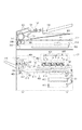
図1は、本実施形態に係る画像形成装置の一例であるMFP100を示す図である。なお、MFPは、Multi Function Peripheralの略である。
<Example 1>
FIG. 1 is a diagram illustrating an
MFP100は、コントローラ部101、印刷部107、読取部109、操作パネル110、回線I/F112、原稿台131、ADF132、原稿有無検知センサ133、原稿端検知センサ134を有する。
The MFP 100 includes a
コントローラ部101は、CPU102、RAM103、ROM104、印刷部I/F106、読取部I/F108、MODEM111、USB I/F115、ネットワークI/F118、画像処理部140、メモリ部150を有する。これらのユニットはシステムバス105によって接続されている。
The
CPU102は、各種プログラムを実行することによって、MFP100を統括的に制御する。
The
RAM103は、CPU102のワークメモリとして機能する。
The
ROM104は、CPU102によって読みだされる種々のプログラムを記憶する。
The
印刷部I/F106は、印刷部107に画像信号を出力するインタフェースである。印刷部107は、給紙カセットと、画像形成部と、排紙部とを有し、給紙カセットから給紙したシートに、画像形成部によって画像を印刷し、排紙部に当該シートを排紙する。
The printing unit I / F 106 is an interface that outputs an image signal to the
読取部I/F108は、読取部109からの読取画像信号を入力するインタフェースである。読取部109は、原稿台131に載置された原稿を読み取り、読み取った原稿の画像を示す画像データを読取部I/F108を介してCPU102に入力する。また、読取部109は、ADF(自動原稿搬送装置)132によって搬送される原稿を読み取り、読み取った原稿の画像を示す画像データを読取部I/F108を介してCPU102に入力する。CPU102は、読取部I/F109より入力された画像データをメモリ部150に記憶し、画像処理部140に処理させ、処理された画像データを、印刷用の画像データとして印刷部I/F106に出力する。なお、ADF132は、ADFに載置された原稿が有るか否かを検知するための原稿有無検知センサ133と、搬送される原稿の端を検知するための原稿端検知センサ133を有し、それぞれ、検知した信号をCPU102に伝える。
A reading unit I /
操作パネル110は、タッチパネル付きの液晶表示部を有し、操作画面やメッセージを表示する。また、操作部110は、タッチパネルまたはハードキーを介してユーザから指示を受け付ける。
The
MODEM111は、回線I/F112を介して公衆回線網114に接続されており、図示しない他の画像形成装置やファクシミリ装置、電話機などと通信処理を行う。回線I/F112は、公衆回線網114と、一般的に電話線113などで接続される。
The
USBI/F115は、USBメモリを接続するためのインタフェースである。また、USBI/F115は、外部のPCとUSBI/F115を介して接続するためにも用いられる。
The USB I /
ネットワークI/F116は、ネットワーク121との通信を制御する。
The network I /
画像処理部140は、画像データに対して変倍処理や、回転処理、消去処理等を行う。
The
メモリ部150は、画像データや、プログラムを記憶する記憶部である。メモリ部150は、HDD(Hard Disk Drive)やSSD(Solid State Drive)によって構成される。
The
次に、図2のMFP100の断面図を用いて、MFP100の構成について説明する。
Next, the configuration of
MFP100は、ADF132を有する。ADF132に積載された原稿は、その積載順に従って、先頭から順次1枚ずつプラテンガラス302上へ搬送される。その後、原稿はプラテンガラス302上でスキャンされ、排出トレイ303に排出される。
The
原稿を誘導する原稿搬送路には、ステッピングモータによって駆動される搬送ローラ305、原稿の先端及び後端を検知する原稿端検知センサ134が設けられている。
In the document conveyance path for guiding the document, a
ADF132に積載された原稿は、ステッピングモータによって駆動される搬送ローラ305によって、一定の搬送速度で搬送される。この搬送速度は、MFP100の工場出荷時に決められ、予めHDD104に記憶されているものとする。
Documents stacked on the
ここで、ADF132に載置された原稿のサイズの求め方を説明する。まず、ユーザは、ADF301に備えられた原稿の幅ガイドを原稿の幅に合わせる。原稿の幅ガイドには、原稿の主走査方向の長さをCPU102に伝えるためのセンサが備えられている。CPU102は、原稿の幅ガイドからの信号を受け取って、原稿の主走査方向の長さを取得することができる。CPUは、取得した原稿の主走査方向の長さをRAM103に記憶しておく。
Here, how to obtain the size of the document placed on the
次に、副走査方向の長さの取得の仕方を説明する。CPU102は、原稿の先端が原稿検知センサ306を通過する時刻t1をRAM103に記憶し、原稿の後端が原稿検知センサ306を通過する時刻t2をRAM103に記憶する。そして、t2からt1を減算した差を算出し、算出された差と搬送速度の積を求めることによって、原稿の副走査方向(搬送方向)の長さを取得することができる。CPUは、取得した原稿の副走査方向の長さをRAM103に記憶しておく。
Next, how to obtain the length in the sub-scanning direction will be described. The
そして、CPU102は、RAM103に記憶された原稿の主走査方向の長さと、副走査方向の長さを持つシートのサイズを特定する。特定されたシートのサイズは、HDD104に保存され、その後、CPU102は、特定されたシートのサイズ分の読取領域で、ADF132によって搬送される原稿の画像を読み取る。
Then, the
そして、原稿が、原稿流し読み位置を一定の速度で搬送される際に、光学ユニット307は、原稿流し読み位置に移動し、等速で搬送される原稿を光源によって照射する。原稿からの反射光は、複数のミラー308、309、310、及び、レンズ311を介してCCDイメージセンサ(以下、「CCD」と称する。)312へ導かれる。これにより、走査された原稿の画像がCCD312によって読み取られる。CCD312によって随時読み取ることで色ごと(R、G、B)の画像データが生成され、当該画像データは保存または印刷のためにメモリ部124に転送される。
Then, when the document is conveyed at the document flow reading position at a constant speed, the
印刷部(図1の印刷部107に対応する)は、シアン(C)、マゼンタ(M)、イエロー(Y)、ブラック(K)のトナーによって画像を形成するための4つの現像ユニットを有し、カラー画像及びモノクロ画像を形成する。
The printing unit (corresponding to the
印刷部は、レーザ露光部401、回転多面鏡(ポリゴンミラー)406、感光ドラム402、作像部403、定着部404、フラッパ405、反転用パス408を有する。また、プリンタ部は、給紙カセット410、給紙カセット411を有する。
The printing unit includes a
レーザ露光部401は、画像データに応じて変調されたレーザ光などの光線を等角速度で回転する回転多面鏡(ポリゴンミラー)406に入射させ、反射走査光として感光ドラム402に照射する。
The
作像部403は、感光ドラム402を回転駆動し、帯電器によって帯電させた後、レーザ露光部401によって感光ドラム402上に形成された潜像をトナーによって現像する。そして、そのトナー像をシートに転写し、その際に転写されずに感光ドラム402上に残った微小トナーを回収するといった一連の電子写真プロセスの現像ユニット(現像ステーション)を4つ持つことで実現している。シアン(C)、マゼンタ(M)、イエロー(Y)、ブラック(K)の順に並べられた4つの現像ユニットは、シアンの現像ユニットによる作像開始から所定時間経過後に、マゼンタ、イエロー、ブラックの現像ユニットによる作像を順次実行していく。このタイミング制御によって、シート上に色ずれのないカラー画像が転写される。
The
定着部404は、ローラやベルトの組み合わせによって構成され、ハロゲンヒータなどの熱源を内蔵し、作像部403によってトナー像が転写されたシート上のトナーを、熱と圧力によって溶解、定着させる。
The fixing
給紙カセット410〜411は、それぞれシートを保持することができる。本実施形態では、給紙カセット410及び給紙カセット411に保持可能なシートのサイズは、A5サイズ、A4サイズ、B5サイズであるものとする。なお、A5サイズは、148mm×210mmであり、A4サイズは210mm×297mmであり、B5サイズは、182mm×257mmである。
Each of the
MFP100は、給紙カセット410〜411のうちのいずれかからシートを給紙し、給紙されたシートに対して、作像部403で作像された画像を転写する。そして、転写された画像を定着部404によってシートに定着させる。そして、MFP100は、画像が形成された面を下に向けてシートを排紙する場合(フェイスダウン排紙をする場合)、フラッパ407によってシートを反転パス405に導き、反転させたシートを排紙トレイ415に排紙する。一方、画像が形成された面を上に向けてシートを排紙する場合(フェイスアップ排紙をする場合)、フラッパ407によってシートを反転パス405に導かずに排紙トレイ415に排紙する。
The
また、シートの両面に画像を印刷する場合、フラッパ407によってシートを反転パス405に導き、シートの後端をローラ409によって挟持させた後、そのシートを両面搬送パス408に導く。両面搬送パス408に導かれたシートは、再び作像部403まで搬送され、シートの裏面に作像部403によって画像が印刷される。裏面に画像が印刷されたシートは、排紙トレイ415に排紙される。
When printing images on both sides of the sheet, the sheet is guided to the
なお、センサS1〜S13は、搬送路上のシートの状態を検知するために設けられている。CPU102は、これらのセンサS1〜13からの信号に基づいて、搬送路上でシートがジャムを起こしていないかを判断している。
The sensors S1 to S13 are provided for detecting the state of the sheet on the conveyance path. The
このようにして、MFP100は、シートに画像を印刷する印刷処理を実行する。
In this way, the
次に、図3を用いて、図2に示したMFP100が有する操作パネル110について説明する。
Next,
操作パネル110は、ハードキーによるユーザ操作を受付けるキー入力部901、ソフトキー(表示キー)を表示可能で、当該ソフトキーによるユーザ操作を受付けるタッチパネル部902を有する。
The
まず、キー入力部901について説明する。図3に示すように、キー入力部901は、操作部電源スイッチ903を備える。MFP100が、スタンバイモード(通常動作状態)のときに、操作部電源スイッチ903がユーザによって押されると、CPU102は、MFP100を、スタンバイモードからスリープモード(消費電力を抑えている状態)に切り替える。一方、MFP100が、スリープモードのときに、操作部電源スイッチ903がユーザによって押されると、CPU102は、MFP100を、スリープモードからスタンバイモードに切り替える。
First, the key input unit 901 will be described. As shown in FIG. 3, the key input unit 901 includes an operation
スタートキー905は、コピー動作や、データの送信動作を、MFP100に実行させる指示をユーザから受付けるためのキーである。
A
ストップキー904は、コピー動作や、データの送信動作を中断する指示をユーザから受付けるためのキーである。
A
テンキー906は、各種設定の置数の設定をユーザにより実行するためのキーである。
A
次に、タッチパネル部902について説明する。タッチパネル部902は、LCD(Liquid Crystal Display:液晶表示部)と、その上に貼られた透明電極からなるタッチパネルシートとを有する。当該タッチパネル部902は、ユーザからの各種設定を受付ける機能と、ユーザに情報を提示する機能とを有する。
Next, the
図4は、MFP100の起動時等にタッチパネル902に表示される操作画面601である。ユーザは、この操作画面601を操作して、印刷倍率や、印刷用のシートを給紙する給紙カセット、部数等のコピーに関する設定を行う。
FIG. 4 shows an
印刷倍率には、初期値として100%(等倍)が設定されている。ユーザは、100%の表示をタッチした後、テンキー906によって、50%〜200%のうちの任意の印刷倍率を入力することによって、印刷倍率を設定することができる。コピーが開始されると、CPU102は、読み取った原稿の画像を、設定された印刷倍率で変倍して、シートに印刷する。
The print magnification is set to 100% (same size) as an initial value. The user can set the print magnification by touching the 100% display and inputting an arbitrary print magnification of 50% to 200% with the
印刷用のシートを給紙する給紙カセットには、初期値として、給紙カセット1が設定されている。ユーザは、給紙カセットの表示をタッチした後、表示される選択肢(給紙カセット1または給紙カセット2)の中から、印刷用のシートを給紙する給紙カセットとして使用したい給紙カセットを選択する。なお、給紙カセット1は、図2の給紙カセット410に対応し、給紙カセット2は、図2の給紙カセット411に対応する。コピーが開始されると、CPU102は、設定された給紙カセットからシートを給紙するよう制御する。
A
部数には、初期値として、「1」が設定されている。ユーザは、「1」の表示をタッチした後、テンキー906を操作することによって部数を設定する。コピーが開始されると、読取部109によって読み取った一連の原稿の画像を、設定された部数分、シートに印刷する。
The number of copies is set to “1” as an initial value. The user touches the display of “1” and then operates the
また、MFP100は、応用機能として、両面印刷機能、縮小レイアウト機能、枠消し機能等の複数の機能を有している。
Further, the
ユーザは、これらの機能の設定も、操作画面601を操作して行うことができる。
The user can also set these functions by operating the
両面印刷機能は、読取部109によって読み取った原稿の画像を、シートの両面に印刷する機能である。両面印刷機能には、初期値として、片面印刷を行うよう設定されている。ユーザによって、「両面:OFF」がタッチされると、CPU102は、タッチパネル部902に図5に示す画面607を表示させる。
The duplex printing function is a function for printing an image of a document read by the
図5に示す画面607には、「ON」キーと「OFF」キーが表示される。ユーザによって「ON」キーが押されると、CPU102は、両面印刷が設定されたことを示す情報をRAM103に記憶する。一方、ユーザによって「OFF」キーが押されると、CPU102は、片面印刷が設定されたことを示す情報をRAM103に記憶する。両面印刷を行うよう設定された状態でコピーが開始されると、CPU102は、シートの両面に画像を印刷するよう制御する。一方、片面印刷を行うよう設定された状態でコピーが開始されると、CPU102は、シートの片面に画像を印刷するよう制御する。
On the
縮小レイアウト機能は、読取部109によって読み取った複数ページの原稿の画像を縮小して、1枚のシートに並べて印刷する機能である。縮小レイアウト機能には、初期値としてOFFが設定されている。つまり、1ページの原稿の画像を、1枚のシートに印刷するよう設定されている。ユーザによって、「縮小レイアウト:OFF」がタッチされると、CPU102は、タッチパネル部902に図6に示す画面604を表示させる。
The reduced layout function is a function for reducing images of a plurality of pages of originals read by the
図6に示す画面604には、「2in1」キー、「4in1」キー、「OFF」キーが表示される。ユーザによって「2in1」キーが押されると、CPU102は、読み取った原稿の複数ページの画像を50%に縮小し、1枚のシートにつき2ページの画像を並べて印刷するよう設定されたことを示す情報をRAM103に記憶する。ユーザによって「4in1」キーが押されると、CPU102は、読み取った原稿の複数ページの画像を25%に縮小し、1枚のシートにつき4ページの画像を並べて印刷するよう設定されたことを示す情報をRAM103に記憶する。ユーザによって「OFF」キーが押されると、CPU102は、読み取った原稿の画像を縮小せずに、1枚のシートに印刷するよう設定されたことを示す情報をRAM103に記憶する。コピーが開始されると、CPU102は、読取部109によって読み取った原稿の複数ページの画像を、縮小レイアウトの設定に従って、シートに印刷するよう制御する。
A “2 in 1” key, a “4 in 1” key, and an “OFF” key are displayed on the
この縮小レイアウト機能を使用するために、ユーザは、原稿のサイズを設定する必要がある。その理由は、1枚のシートに複数ページの画像を並べて印刷する際に、原稿のサイズより大きな領域を読み取ると各ページの画像に余白が発生し、見栄えが良くないからである。 In order to use this reduced layout function, the user needs to set the size of the document. The reason is that when printing an image of a plurality of pages side by side on a single sheet, if an area larger than the size of the original is read, a margin is generated in the image of each page and the appearance is not good.
そこで、図6に示す画面には、「A4」キー、「B5」キー、「A5」キーが表示される。CPU102は、ユーザによって押されたサイズを、原稿のサイズとしてRAM103に記憶する。
Therefore, an “A4” key, a “B5” key, and an “A5” key are displayed on the screen shown in FIG. The
枠消し機能は、読取部109によって読み取った画像の周囲を消去し、周囲が消去された画像をシートに印刷する機能である。枠消し機能には、初期値としてOFFが設定されている。つまり、原稿の画像の周囲を消去しないよう設定されている。ユーザによって、「枠消し:OFF」がタッチされると、CPU102は、タッチパネル部902に図7に示す画面605を表示させる。
The frame erasing function is a function of erasing the periphery of the image read by the
図7に示す画面605には、枠消し機能によって消去すべき幅を設定するための幅設定領域が表示される。
A
ユーザによって幅設定領域がタッチされ、テンキー906によって消去すべき幅が設定されると、CPU102は、設定された幅分の画像を消去するよう設定した情報をRAM103に記憶する。コピーが開始されると、CPU102は、読み取った原稿の画像の周囲を、ユーザによって設定された幅分消去し、周囲が消去された画像をシートに印刷するよう制御する。
When the user touches the width setting area and the width to be deleted is set by the
この枠消し機能を使用するために、ユーザは、原稿のサイズを設定する必要がある。その理由は、原稿の画像の周囲を消去する際に、消去する基準となる原稿のサイズが決まっていないと、CPU102は、どの範囲を消去すればよいか決定できないからである。
In order to use this frame erasing function, the user needs to set the size of the document. The reason is that when erasing the periphery of the original image, the
そこで、図7に示す画面には、「A4」キー、「B5」キー、「A5」キーが表示される。CPU102は、ユーザによって押されたサイズを、原稿のサイズとしてRAM103に記憶する。
Therefore, an “A4” key, a “B5” key, and an “A5” key are displayed on the screen shown in FIG. The
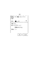
以上のように、ユーザは、コピーに関する設定を行う。そして、CPU102は、ユーザによって設定された設定内容をRAM103に記憶する。また、CPU102は、設定された内容を操作画面に反映させる。例えば、図6に示す画面604で、「2in1」が設定され、原稿サイズとして「A4」が設定され、OKキーが押された場合、CPU102は、図8に示す画面602をタッチパネル部902に表示させる。
As described above, the user performs settings related to copying. Then, the
この画面602には、縮小レイアウトとして2in1が設定され、原稿のサイズがA4に設定されていることが表示されている。ユーザは、このような画面602を見て、現在設定されている設定内容を確認することができる。
This
以上に説明したMFP100は、ADF132には原稿のサイズを検知するセンサ133を備えているが、原稿台131には原稿のサイズを検知するセンサを備えていない。それによって、MFP100のコストを抑えている。
In the
さらに、MFP100は、基本的には、原稿のサイズをユーザに入力させず、印刷に使用する給紙カセットに設定されたシートのサイズを、原稿のサイズとして用いて原稿の読み取りを行う。それによって、ユーザがコピーを取るたびにかかる負担を軽減することができる。
Furthermore, the
従来は、このような原稿のサイズを検知するセンサを持たない装置の場合、図14(a)に示すように、センター基準で原稿を読み取る。具体的に、ユーザは、図14(a)に示す原稿の基準点1302に原稿1304のセンターラインを合わせる。そして、従来の装置は、原稿の基準点1302を中心に、ユーザによって設定された記録紙サイズ分の読取領域1301を設定し、その読取領域1301の画像を読み取る。
Conventionally, in the case of an apparatus that does not have such a sensor for detecting the size of a document, the document is read on the basis of the center as shown in FIG. Specifically, the user aligns the center line of the document 1304 with the
それによって、原稿の画像は、印刷用のシートの表面の1309に示す位置に印刷され、印刷用のシートの裏面の1310に示す位置に印刷される。その結果、シートの表面に印刷された画像の位置1309と、シートの裏面に印刷された画像の位置1310とが一致する。
As a result, the image of the original is printed at a position indicated by 1309 on the front surface of the printing sheet and printed at a position indicated by 1310 on the back surface of the printing sheet. As a result, the
しかしながら、センター基準で原稿を読み取る場合、ユーザは、原稿のセンターラインを合わせるために、原稿の位置の微調整を行わなければならない。 However, when a document is read based on the center reference, the user must finely adjust the position of the document in order to align the center line of the document.
そこで、本実施形態に係るMFP100は、原稿台に原稿のサイズを検知するセンサを設けないことにより、MFP100のコストを抑えつつ、突き当て基準で原稿を読み取るようにした。それによって、ユーザは、原稿の角を、原稿台の角に付き当てるという容易な操作で原稿の位置を合わせることができる。
In view of this, the
例えば、ユーザは、図14(b)のように、原稿台の角(基準点1402)に、原稿の角を合わせる。 For example, as shown in FIG. 14B, the user aligns the corner of the document with the corner of the document table (reference point 1402).
そしてコピーを開始させるが、このときに原稿台の角を基準に、ユーザによって設定された印刷用のシートのサイズ分の読取領域1401を設定して、その読取領域1401の画像を読み取ると次のような課題が発生する。
Then, copying is started. At this time, the
原稿の画像は、印刷用のシートの表面の1409に示す位置に印刷され、印刷用のシートの裏面の1410に示す位置に印刷される。その結果、シートの表面に印刷された画像の位置1409とシートの裏面1410に印刷された画像の位置がずれてしまい、印刷物の品質が低下してしまう。
The image of the original is printed at a position indicated by 1409 on the front surface of the printing sheet, and is printed at a position indicated by 1410 on the back surface of the printing sheet. As a result, the
そこで、本実施形態に係るMFP100では、片面印刷する場合には、原稿のサイズを印刷用のシートのサイズに設定して、原稿の画像を読み取ることによって、ユーザの手間を抑える。一方、両面印刷する場合には、原稿の読取サイズをユーザに入力させ、ユーザによって入力された読取サイズに従って原稿の画像を読み取るよう制御することによって、印刷物の品質が低下してしまうことを防止することができる。つまり、原稿のサイズを検知するセンサを設けずにコストを抑え、ユーザが原稿の位置を合わせるための操作負荷を軽減しつつ、原稿の表面の画像と裏面の画像の印刷位置を同じにすることができる。
Therefore, in the
このようなMFP100の処理の詳細を図9のフローチャートを用いて説明する。図9のフローチャートに示す処理は、CPU102が、ROM104に記憶されたプログラムをRAM103に読み出して実行することによって行われる。
Details of the processing of the
まず、S901で、CPU102は、タッチパネル部902に図4に示す操作画面を表示させる。
First, in step S901, the
S902で、CPU102は、操作画面の給紙カセットの表示が押されたか否かを判定する。変更指示を受け付けたと判定した場合に、CPU102はS922に処理を進める。一方、変更指示を受け付けていないと判定した場合、CPU102はS903に処理を進める。
In step S902, the
S922で、CPU102は、給紙カセットを変更するための操作画面をタッチパネル部902に表示させる。そして、S923で、CPU102は、印刷に用いる給紙カセットの設定をユーザから受け付け、S924で、CPU102は、受け付けた設定値をRAM103に記憶する。具体的に、CPU102は、給紙カセット1または給紙カセット2を受け付け、受け付けた設定値をRAM103に記憶する。なお、給紙カセット1及び給紙カセット2のそれぞれに収納されているシートのサイズは、事前にユーザによって設定されているものとする。なお、給紙カセット1及び給紙カセット2のそれぞれに設定可能なシートのサイズは、A4、B5、A5であるものとする。給紙カセット1にA4サイズのシートが設定されている場合、CPU102は、給紙カセット1を使用するよう設定された場合に、印刷に用いるシートのサイズがA4であると認識する。また、給紙カセット1にA5サイズのシートが設定されている場合、CPU102は、給紙カセット1を使用するよう設定された場合に、印刷に用いるシートのサイズがA5であると認識する。S925で、CPU102は、受け付けた設定値を操作画面に反映させて、S906に処理を進める。
In step S922, the
S902からS903に処理を進めた場合、CPU102は、操作画面の縮小レイアウトの項目がタッチされ、縮小レイアウト機能が選択されたか否かを判定する。縮小レイアウト機能が選択されたと判定した場合にCPU102はS917に処理を進め、縮小レイアウト機能が選択されていないと判定した場合にCPU102はS904に処理を進める。
When the process proceeds from step S902 to step S903, the
S917で、CPU102は、図6に示す画面をタッチパネル部902に表示させる。S918で、CPU102は、「2in1」、「4in1」、「OFF」の中から、任意のレイアウト方法を受け付ける。S919で、CPU102は、受け付けたレイアウト方法をRAM103に記憶する。そして、S921で、CPU102は、受け付けた設定値を操作画面に反映させて、S906に処理を進める。
In step S917, the
S903からS904に処理を進めた場合、CPU102は、操作画面の枠消しの項目がタッチされ、枠消し機能が選択されたか否かを判定する。枠消し機能が選択されたと判定した場合に、CPU102はS912に処理を進め、枠消し機能が選択されていないと判定した場合に、CPU102はS905に処理を進める。
When the process proceeds from step S903 to step S904, the
S912で、CPU102は、図7に示す画面をタッチパネル部902に表示させる。S913で、CPU102は消し幅の設定を受け付け、S914で、CPU102は原稿のサイズを受け付け、S915で、それぞれの設定値をRAM103に記憶する。S916で、CPU102は、受け付けた設定値を操作画面に反映させて、S905に処理を進める。
In step S912, the
S904からS905に処理を進めた場合、CPU102は、操作画面の両面印刷機能が選択されたか否かを判定する。両面印刷機能が選択されたと判定した場合に、CPU102はS908に処理を進め、両面印刷機能が選択されていないと判定した場合に、CPU102はS906に処理を進める。
When the process proceeds from step S904 to step S905, the
S908で、CPU102は、図5に示す画面をタッチパネル部902に表示させる。S909で、CPU102は、「ON」、「OFF」のいずれかの選択を受け付ける。S910で、CPU102は、受け付けた設定値をRAM103に記憶する。S911で、CPU102は、受け付けた設定値を操作画面に反映させて、S906に処理を進める。
In step S908, the
S906で、CPU102は、ユーザによってスタートキー905が押されたか否か、つまり印刷指示を受け付けたか否かを判定する。スタートキー905が押されたと判定した場合、S907に処理を進め、スタートキー905が押されていないと判定した場合、S902に処理を進める。
In step S906, the
S907で、CPU102は、RAM103に記憶されたコピーの設定に基づいてコピーを実行する。
In step S <b> 907, the
次に、図10を用いて、S907におけるコピーの詳細を説明する。図10のフローチャートに示す処理は、CPU102が、ROM104に記憶されたプログラムをRAM103に読み出して実行することによって行われる。
Next, details of copying in S907 will be described with reference to FIG. The process shown in the flowchart of FIG. 10 is performed by the
S1001で、CPU102は、原稿有無検知センサ133からの情報に従って、MFP100のADF132に原稿がセットされているか否かを判定する。ADF132に原稿がセットされていると判定した場合、CPU102は、S1022に処理を進め、ADF132に原稿がセットされていないと判定した場合、CPU102は、S1002に処理を進める。
In step S <b> 1001, the
S1002で、CPU102は、RAM103に記憶された設定値に従って、両面印刷を行うよう設定されているか否かを判定する。両面印刷を行うよう設定されている場合に、CPU102はS1006に処理を進め、片面印刷を行うよう設定されている場合に、CPU102はS1004に処理を進める。
In step S <b> 1002, the
S1003で、CPU102は、RAM103に記憶された印刷用のシートのサイズを原稿のサイズとして決定する。そして、CPU102は、原稿台131の領域のうち、原稿台の角を基準に、決定された原稿のサイズ分の領域の画像を読取部109に読み取らせる。例えば、印刷用のシートのサイズがA4サイズであれば、CPU102は、読取部109に、原稿台の角を基準にA4サイズ(210mm×297mm)の領域の画像を読み取らせる。そして、CPU102は、読み取った画像をメモリ部150に記憶する。
In step S <b> 1003, the
S1004で、CPU102は、読取部109によって読み取られ、メモリ部150に記憶された原稿の画像を、印刷部107に印刷させる。なお、このとき、CPU102は、必要に応じて、RAM103に記憶された設定値に従って画像を処理して印刷する。例えば、2in1が設定されている場合、CPU102は、画像処理部140によって画像を50%に縮小し、縮小された画像をシートに印刷するよう制御する。また、3mmの枠消しが設定されている場合、CPU102は、原稿の上端から3mm、右端から3mm、左端から3mm、下端から3mmの画像を画像処理部140に消去させ、当該画像を印刷部107に印刷させる。また、複数部数印刷するよう設定されている場合、CPU102は、読み取られた原稿の画像を、印刷部107に設定された部数分印刷させる。そして処理を終了する。
In step S <b> 1004, the
一方、S1002からS1005に処理を進めた場合は、原稿台に載置された原稿を読み取って、読み取った原稿の画像をシートの両面に印刷する場合に相当する。この場合、印刷用のシートの表裏に印刷された画像の印刷位置がずれないように、印刷用のシートのサイズではなく、原稿のサイズを特定し、特定した原稿のサイズに従って読取領域を決めなければならない。そこで、S1005で、CPU102は、原稿のサイズが既に設定されているか否かを判断する。例えば、縮小レイアウト機能の設定過程(図9のS915)で原稿のサイズが既に設定されている場合、または、枠消し機能の設定過程(図9のS919)で原稿のサイズが既に設定されている場合には、その原稿のサイズを使用することができる。そのため、縮小レイアウト機能または枠消し機能によって、原稿のサイズが既に設定されている場合、CPU102は、原稿のサイズが既に設定されていると判定し、S1009に処理を進める。一方、縮小レイアウト機能、及び、枠消し機能のいずれの機能もOFFの状態であり、原稿のサイズがまだ設定されていない場合、CPU102は、S1006に処理を進める。
On the other hand, when the processing proceeds from S1002 to S1005, it corresponds to a case where the document placed on the document table is read and images of the read document are printed on both sides of the sheet. In this case, in order not to shift the printing position of the image printed on the front and back of the printing sheet, the size of the document must be specified, not the size of the printing sheet, and the reading area must be determined according to the specified size of the document. I must. In step S1005, the
S1006で、CPU102は、原稿のサイズを受け付けるための画面を、タッチパネル部902に表示させる。図11は、原稿のサイズを受け付ける画面の一例である。図11に示す画面701には、「A4」キー、「B4」キー、「A5」キーが表示されている。
In step S <b> 1006, the
S1007で、CPU102は、ユーザから原稿のサイズを受け付ける。ユーザによって「A4」キーが押されると、CPU102は、S1008で、原稿のサイズがA4サイズであることを示す情報をRAM103に記憶する。ユーザによって「B4」キーが押されると、CPU102は、S1008で、原稿のサイズがB4サイズであることを示す情報をRAM103に記憶する。ユーザによって「A5」キーが押されると、CPU102は、S1008で、原稿のサイズがA5サイズであることを示す情報をRAM103に記憶する。
In step S1007, the
S1009で、CPU102は、受け付けた原稿のサイズに従って読取処理を実行する。S1009の処理の詳細を図12を用いて説明する。
In step S <b> 1009, the
図12のフローチャートに示す処理は、CPU102が、ROM104に記憶されたプログラムをRAM103に読み出して実行することによって行われる。
The process shown in the flowchart of FIG. 12 is performed by the
まずS1501で、CPU102は、受け付けた原稿のサイズを読取範囲に設定する。例えば、受け付けた原稿のサイズがA4サイズであれば、CPU102は、読取部109に、A4サイズ(210mm×297mm)の領域の画像を読み取らせる。
In step S1501, the
そして、S1502で、CPU102は、原稿の表面の読み取りであるか、原稿の裏面の読み取りであるかを判定する。読取処理を開始してから、奇数枚目の読み取り処理である場合、CPU102は、原稿の表面の読み取りであると判定し、S1503に処理を進める。一方、読取処理を開始してから、偶数枚目の読取処理である場合、CPU102は、原稿の裏面の読み取りであると判定し、S1506に処理を進める。
In step S1502, the
S1503で、CPU102は、設定された読取範囲のみの原稿の画像を読み取り、S1504で、読み取った画像をメモリ部150に記憶する。そして、S1505に処理を進める。
In step S <b> 1503, the
一方、S1502からS1506に処理を進めた場合、CPU102は、設定された読取範囲のみの原稿の画像を読取、S1507で、読み取った画像をメモリ部150に記憶する。そして、S1508に処理を進める。S1508で、CPU102は、記憶した裏面の画像の印刷位置が、表面の画像と一致するように画像をずらすための制御を実行する。ずらすための制御とは、シートに印刷される画像の印刷位置がシートの表裏で一致するようメモリ上の記憶位置を変える方法である。また、ここでは、メモリ上の記憶位置を変えず、シートに印刷時にシートに印刷される画像の印刷位置がシートの表裏で一致するよう印刷開始タイミングを変えてもよい。そして、S1505に処理を進める。
On the other hand, when the processing proceeds from step S1502 to step S1506, the
S1505で、CPU102は、原稿の読み取りが完了したか否かを判定する。具体的には、原稿が1面分読まれるたびに、「次の原稿を読み取る場合、スタートキーを押してください。」というメッセージと、「読取終了」キーをタッチパネル部902に表示させる。そして、CPU102は、スタートキー905が押下された場合に、次の原稿を読み取らせ、「読取終了」キーが押下された場合に、原稿の読み取りを完了する。CPU102は、原稿の読み取りが完了したと判定した場合、S1010に処理を進め、次の原稿を読み取ると判定された場合、S1502に処理を進める。
In step S <b> 1505, the
そして、S1010で、CPU102は、読取部109によって読み取られ、メモリ部150に記憶された原稿の画像を、印刷部107に印刷させる。なお、このとき、CPU102は、原稿の表裏で、画像の印刷位置が一致するように画像を印刷するよう制御する。例えば、S1508で、シートに印刷される画像の印刷位置がシートの表裏で一致するようメモリの記憶位置が変えられている場合には、メモリ上の画像をそのままシートの表裏に印刷する。一方、S1508で、メモリ上の記憶位置を変えず、印刷開始タイミングを変えるよう決定されている場合、CPU102は、シートに印刷時にシートに印刷される画像の印刷位置がシートの表裏で一致するよう印刷開始タイミングを変える。また、必要に応じて、RAM103に記憶された設定値に従って画像を処理して印刷する。例えば、2in1が設定されている場合、CPU102は、画像処理部140によって画像を50%に縮小し、縮小された画像をシートに印刷するよう制御する。また、3mmの枠消しが設定されている場合、CPU102は、原稿の上端から3mm、右端から3mm、左端から3mm、下端から3mmの画像を画像処理部140に消去させ、当該画像を印刷部107に印刷させる。また、複数部数印刷するよう設定されている場合、CPU102は、読み取られた原稿の画像を、印刷部107に設定された部数分印刷させる。そして処理を終了する。
In step S <b> 1010, the
一方、S1002からS1011に処理を進めた場合は、原稿をADF132によって搬送し、搬送された原稿の画像を読み取る場合に相当する。この場合、ADF132はセンサ133を有しているので、ユーザが原稿のサイズを指定する操作をしていなくとも、原稿を搬送し、原稿を読み取る際に、CPU102は、原稿のサイズを認識することができる。
On the other hand, when the processing proceeds from S1002 to S1011, it corresponds to a case where the original is conveyed by the
S1011で、CPU102は、RAM103に記憶された設定値に従って、両面印刷を行うよう設定されているか否かを判定する。両面印刷を行うよう設定されている場合に、CPU102はS1012に処理を進め、片面印刷を行うよう設定されている場合に、CPU102はS1016に処理を進める。
In step S <b> 1011, the
S1012で、CPU102は、ADF132に載置された原稿を1枚ずつ搬送する。そして、S1013で、CPU102は、搬送された原稿のサイズを、センサ133からの信号によって特定する。原稿のサイズの測定の仕方は、図3を用いて説明した通りである。
In step S <b> 1012, the
S1014で、CPU102は、ADF132によって搬送される原稿を、原稿台131の領域のうち、RAM103に記憶された原稿のサイズ分の領域の画像を、読取部109に読み取らせる。例えば、印刷用のシートのサイズがA4サイズであれば、CPU102は、読取部109に、A4サイズ(210mm×297mm)の領域の画像を読み取らせる。そして、CPU102は、読み取った画像をメモリ部150に記憶する。
In step S <b> 1014, the
S1015で、CPU102は、読取部109によって読み取られ、メモリ部150に記憶された原稿の画像を、印刷部107に両面印刷させる。なお、このとき、CPU102は、必要に応じて、RAM103に記憶された設定値に従って画像を処理して印刷する。例えば、2in1が設定されている場合、CPU102は、画像処理部140によって画像を50%に縮小し、縮小された画像をシートに印刷するよう制御する。また、3mmの枠消しが設定されている場合、CPU102は、原稿の上端から3mm、右端から3mm、左端から3mm、下端から3mmの画像を画像処理部140に消去させ、当該画像を印刷部107に印刷させる。また、複数部数印刷するよう設定されている場合、CPU102は、読み取られた原稿の画像を、印刷部107に設定された部数分印刷させる。そして処理を終了する。
In step S <b> 1015, the
S1011からS1016に処理を進めた場合、S1016で、CPU102は、ADF132に載置された原稿を1枚ずつ搬送する。そして、S1017で、CPU102は、搬送された原稿のサイズを、センサ133からの信号によって特定する。原稿のサイズの測定の仕方は、図3を用いて説明した通りである。
When the process proceeds from S1011 to S1016, in S1016, the
S1018で、CPU102は、ADF132によって搬送される原稿を、原稿台131の領域のうち、RAM103に記憶された原稿のサイズ分の領域の画像を、読取部109に読み取らせる。例えば、印刷用のシートのサイズがA4サイズであれば、CPU102は、読取部109に、A4サイズ(210mm×297mm)の領域の画像を読み取らせる。そして、CPU102は、読み取った画像をメモリ部150に記憶する。
In step S <b> 1018, the
S1019で、CPU102は、読取部109によって読み取られ、メモリ部150に記憶された原稿の画像を、印刷部107に印刷させる。なお、このとき、CPU102は、必要に応じて、RAM103に記憶された設定値に従って画像を処理して印刷する。例えば、2in1が設定されている場合、CPU102は、画像処理部140によって画像を50%に縮小し、縮小された画像をシートに印刷するよう制御する。また、3mmの枠消しが設定されている場合、CPU102は、原稿の上端から3mm、右端から3mm、左端から3mm、下端から3mmの画像を画像処理部140に消去させ、当該画像を印刷部107に印刷させる。また、複数部数印刷するよう設定されている場合、CPU102は、読み取られた原稿の画像を、印刷部107に設定された部数分印刷させる。そして処理を終了する。
In step S <b> 1019, the
以上のように制御することによって、原稿台に置かれた原稿のサイズを検知するセンサを持たない装置で、原稿のサイズを必要な場合に限ってユーザに設定させることによって、ユーザの操作負荷を減らすことができる。具体的には、原稿の画像を両面印刷する場合に限って、原稿のサイズをユーザに設定させる。それによって、図13に示すように、原稿台の角の基準点1202に突き当てるように原稿1201を載置しても、原稿のない領域1204を読み取ることなく、原稿1201の画像1203を読み取ることができる。裏面に関しても同様に、原稿台の角の基準点1202に突き当てるように原稿1207を載置しても、原稿のない領域1210を読み取ることなく、原稿1207の画像1209を読み取ることができる。そして、印刷用のシートの表面の画像1211の印刷位置と裏面の画像1212の印刷位置とがずれないように印刷を実行することができる。
By controlling as described above, the user does not have a sensor for detecting the size of the document placed on the document table, and the user's operation load is reduced by allowing the user to set the size of the document only when necessary. Can be reduced. More specifically, the user is allowed to set the document size only when the original image is printed on both sides. As a result, as shown in FIG. 13, even if the original 1201 is placed so as to abut the
(その他の実施形態)
上述した実施形態では、原稿のサイズをユーザに設定された場合に、原稿のない領域を読み取らない例について説明した。しかしながら、本発明はこれに限られない。例えば、CPU102は、一旦、原稿のない領域も読み取った後、原稿のサイズに従って、原稿のない領域の画像を消去し、その領域の画像を印刷用のシートに印刷しないようにしてもよい。
(Other embodiments)
In the above-described embodiment, an example in which an area without a document is not read when the size of the document is set by the user has been described. However, the present invention is not limited to this. For example, the
本実施形態におけるフローチャートに示す機能は、ネットワーク又は各種記憶媒体を介して取得したソフトウエア(プログラム)をコンピュータパソコン等の処理装置(CPU、プロセッサ)にて実行することでも実現できる。 The functions shown in the flowchart in the present embodiment can also be realized by executing software (program) acquired via a network or various storage media by a processing device (CPU, processor) such as a computer personal computer.
102 CPU
103 RAM
104 ROM
109 読取部
131 原稿台
132 ADF
102 CPU
103 RAM
104 ROM
109
Claims (12)
前記原稿台に載置された原稿の読取処理を実行する読取手段と、
片面印刷するか両面印刷するかを設定する設定手段と、
原稿のサイズを示す情報をユーザから受け付ける受付手段と、
前記設定手段によって両面印刷するよう設定された場合は、前記受付手段によって受け付けた原稿のサイズを示す情報に従って読取領域を決定し、前記設定手段によって片面印刷するよう設定された場合は、印刷に用いるシートのサイズに従って読取領域を決定する決定手段と、
前記決定手段によって決定された読取領域に従って原稿の読取処理を実行するよう前記読取手段を制御する制御手段と、
前記読取処理によって読み取った画像をシートに印刷する印刷手段と、
を備えることを特徴とする画像形成装置。 An original platen not equipped with a sensor for detecting the original size;
Reading means for executing a reading process of a document placed on the document table ;
A setting means for setting whether single-sided printing or double-sided printing;
Receiving means for receiving information indicating the size of the document from the user;
When the setting unit is set to perform double-sided printing, the reading area is determined according to the information indicating the size of the document received by the receiving unit, and when the setting unit is set to perform single-sided printing, it is used for printing. Determining means for determining a reading area according to a sheet size;
Control means for controlling the reading means so as to execute a document reading process according to the reading area determined by the determining means;
Printing means for printing an image read by the reading process on a sheet;
An image forming apparatus comprising:
前記受付手段は、前記表示部に表示される画面を介して、前記原稿のサイズを示す情報を受け付けることを特徴とする請求項1又は2に記載の画像形成装置。 Further comprising display control means for displaying a screen for receiving information indicating the size of the document on a display unit;
The image forming apparatus according to claim 1, wherein the receiving unit receives information indicating a size of the document via a screen displayed on the display unit.
を更に備え、
前記制御手段は、ユーザによって前記原稿台に載置された原稿の読取処理を行う場合は、前記決定手段によって決定した読取領域に従って原稿の読取処理を実行し、前記原稿搬送手段によって搬送される原稿の読取処理を行う場合は、前記原稿搬送手段によって搬送される原稿のサイズを検知し、当該検知されたサイズに基づき決定した読取領域に従って読取処理を行うことを特徴とする請求項1乃至5のいずれか1項に記載の画像形成装置。 A document conveying means for conveying the document to the reading means;
When the user performs the reading process of the document placed on the document table by the user, the control unit executes the document reading process according to the reading area determined by the determining unit, and the document conveyed by the document conveying unit 6. The reading process according to claim 1, wherein the size of the document conveyed by the document conveying means is detected and the reading process is performed according to a reading area determined based on the detected size. The image forming apparatus according to claim 1.
片面印刷するか両面印刷するかを設定する設定工程と、
原稿のサイズを示す情報をユーザから受け付ける受付工程と、
前記設定工程で両面印刷するよう設定された場合は、前記受付工程で受け付けた原稿のサイズを示す情報に従って読取領域を決定し、前記設定工程で片面印刷するよう設定された場合は、印刷に用いるシートのサイズに従って読取領域を決定する決定工程と、前記決定工程で決定された読取領域に従って原稿の読取処理を実行するよう前記読取手段を制御する制御工程と、
前記読取処理によって読み取った画像をシートに印刷する印刷工程と、
を備えることを特徴とする画像形成装置の制御方法。 A method for controlling an image forming apparatus including a document table that does not include a sensor that detects the size of a document, and a reading unit that reads a document placed on the document table .
A setting process for setting whether single-sided printing or double-sided printing;
A reception process for receiving information indicating the size of the document from the user;
When it is set to print on both sides in the setting step, the reading area is determined according to the information indicating the size of the document received in the receiving step, and when it is set to print on one side in the setting step, it is used for printing. A determination step of determining a reading area according to the size of the sheet; a control step of controlling the reading unit to execute a document reading process according to the reading area determined in the determination step;
A printing step of printing an image read by the reading process on a sheet;
An image forming apparatus control method comprising:
Priority Applications (3)
| Application Number | Priority Date | Filing Date | Title |
|---|---|---|---|
| JP2012165943A JP6032990B2 (en) | 2012-07-26 | 2012-07-26 | Image forming apparatus, image forming apparatus control method, and program |
| US13/949,537 US10104268B2 (en) | 2012-07-26 | 2013-07-24 | Image forming apparatus, method for controlling same, and storage medium |
| CN201310320599.2A CN103581472B (en) | 2012-07-26 | 2013-07-26 | Image forming device and control method thereof |
Applications Claiming Priority (1)
| Application Number | Priority Date | Filing Date | Title |
|---|---|---|---|
| JP2012165943A JP6032990B2 (en) | 2012-07-26 | 2012-07-26 | Image forming apparatus, image forming apparatus control method, and program |
Publications (3)
| Publication Number | Publication Date |
|---|---|
| JP2014027461A JP2014027461A (en) | 2014-02-06 |
| JP2014027461A5 JP2014027461A5 (en) | 2015-09-10 |
| JP6032990B2 true JP6032990B2 (en) | 2016-11-30 |
Family
ID=49994591
Family Applications (1)
| Application Number | Title | Priority Date | Filing Date |
|---|---|---|---|
| JP2012165943A Active JP6032990B2 (en) | 2012-07-26 | 2012-07-26 | Image forming apparatus, image forming apparatus control method, and program |
Country Status (3)
| Country | Link |
|---|---|
| US (1) | US10104268B2 (en) |
| JP (1) | JP6032990B2 (en) |
| CN (1) | CN103581472B (en) |
Families Citing this family (9)
| Publication number | Priority date | Publication date | Assignee | Title |
|---|---|---|---|---|
| JP6107548B2 (en) * | 2013-08-30 | 2017-04-05 | ブラザー工業株式会社 | Document reading apparatus and storage medium |
| CN107005620B (en) * | 2014-12-12 | 2019-06-21 | 佳能株式会社 | Copy device, the control method of copy device and storage medium |
| JP6354638B2 (en) * | 2015-03-31 | 2018-07-11 | 京セラドキュメントソリューションズ株式会社 | Image reading apparatus, image forming apparatus, and image reading method |
| JP6354642B2 (en) * | 2015-04-06 | 2018-07-11 | 京セラドキュメントソリューションズ株式会社 | Image reading apparatus and image processing apparatus |
| JP6376169B2 (en) * | 2016-04-20 | 2018-08-22 | トヨタ自動車株式会社 | Hybrid vehicle |
| US10859959B2 (en) * | 2016-05-31 | 2020-12-08 | Kyocera Document Solutions Inc. | Image forming apparatus |
| JP6701579B2 (en) * | 2017-03-22 | 2020-05-27 | 京セラドキュメントソリューションズ株式会社 | Image forming apparatus, image forming method, and image forming program |
| JP6817901B2 (en) * | 2017-06-21 | 2021-01-20 | 株式会社沖データ | Image forming device |
| WO2023013464A1 (en) * | 2021-08-05 | 2023-02-09 | 京セラドキュメントソリューションズ株式会社 | Image forming device |
Family Cites Families (32)
| Publication number | Priority date | Publication date | Assignee | Title |
|---|---|---|---|---|
| US5010371A (en) * | 1987-05-12 | 1991-04-23 | Minolta Camera Kabushiki Kaisha | Copying apparatus provided with automatic document feeder |
| US5144372A (en) * | 1987-11-20 | 1992-09-01 | Minolta Camera Kabushiki Kaisha | Copying machine operable in simultaneous multi-color mode |
| JPH01244475A (en) | 1988-03-25 | 1989-09-28 | Ricoh Co Ltd | Copying machine controller |
| JPH10207299A (en) * | 1997-01-22 | 1998-08-07 | Toshiba Corp | Image forming device and method therefor |
| JP4054444B2 (en) * | 1997-07-30 | 2008-02-27 | キヤノン株式会社 | Print control apparatus, print control method, and storage medium |
| JP2001069318A (en) * | 1999-08-27 | 2001-03-16 | Toshiba Tec Corp | Color image forming device |
| JP4834256B2 (en) * | 2000-09-12 | 2011-12-14 | キヤノン株式会社 | Information processing apparatus, print data generation method, print control program, and storage medium |
| US7742198B2 (en) | 2001-09-12 | 2010-06-22 | Seiko Epson Corporation | Image processing apparatus and method |
| JP2004140802A (en) * | 2002-09-24 | 2004-05-13 | Ricoh Co Ltd | Image forming apparatus and printing method |
| JP2004287234A (en) * | 2003-03-24 | 2004-10-14 | Kyocera Mita Corp | Image forming apparatus |
| JP4408039B2 (en) * | 2003-11-13 | 2010-02-03 | キヤノン株式会社 | Information processing apparatus, printing system, information processing method, and printing method |
| JP4155915B2 (en) * | 2003-12-03 | 2008-09-24 | ニスカ株式会社 | Sheet post-processing apparatus and image forming apparatus |
| JP4718419B2 (en) * | 2006-01-27 | 2011-07-06 | 株式会社リコー | Image forming apparatus and file management method |
| JP2007331159A (en) * | 2006-06-13 | 2007-12-27 | Tohoku Ricoh Co Ltd | Printing equipment |
| JP4991411B2 (en) * | 2006-07-28 | 2012-08-01 | キヤノン株式会社 | Image processing method |
| JP4680217B2 (en) * | 2007-03-06 | 2011-05-11 | 京セラミタ株式会社 | Image forming apparatus |
| JP4310713B2 (en) * | 2007-04-06 | 2009-08-12 | コニカミノルタビジネステクノロジーズ株式会社 | Image forming apparatus |
| US8456666B2 (en) * | 2007-07-17 | 2013-06-04 | Xerox Corporation | Printer driver interface and methods |
| KR20090010785A (en) * | 2007-07-24 | 2009-01-30 | 삼성전자주식회사 | Image reading apparatus and controlling method thereof |
| JP4773470B2 (en) * | 2008-02-18 | 2011-09-14 | 株式会社リコー | Document search / print system, digital multi-function peripheral, document search / print method and program |
| JP5161665B2 (en) | 2008-06-17 | 2013-03-13 | キヤノン株式会社 | Image forming apparatus, control method thereof, and computer program |
| JP2010159130A (en) * | 2009-01-08 | 2010-07-22 | Oki Data Corp | Image forming device |
| JP4886053B2 (en) * | 2009-04-23 | 2012-02-29 | シャープ株式会社 | CONTROL DEVICE, IMAGE READING DEVICE, IMAGE FORMING DEVICE, IMAGE READING DEVICE CONTROL METHOD, PROGRAM, AND RECORDING MEDIUM |
| US8711439B2 (en) * | 2009-06-09 | 2014-04-29 | Xerox Corporation | High productivity single pass scanning system |
| JPWO2010150363A1 (en) * | 2009-06-24 | 2012-12-06 | キヤノン株式会社 | Image reading apparatus, image reading apparatus control method, and program |
| JP4973715B2 (en) | 2009-10-28 | 2012-07-11 | ブラザー工業株式会社 | Printing device |
| JP2011146835A (en) | 2010-01-13 | 2011-07-28 | Seiko Epson Corp | Optical reader, method of controlling the same, and program |
| JP5387464B2 (en) * | 2010-03-16 | 2014-01-15 | 株式会社リコー | Image reading apparatus and image forming apparatus |
| US8596523B2 (en) * | 2011-07-28 | 2013-12-03 | Intellectual Ventures Fund 83 Llc | Index print with machine-readable codes |
| JP5917096B2 (en) * | 2011-11-10 | 2016-05-11 | キヤノン株式会社 | Print setting apparatus, print setting method, and program |
| JP5963431B2 (en) * | 2011-12-06 | 2016-08-03 | キヤノン株式会社 | Image forming apparatus, image display method, and program |
| JP5661709B2 (en) * | 2012-09-24 | 2015-01-28 | 株式会社沖データ | Image processing apparatus and image processing method |
-
2012
- 2012-07-26 JP JP2012165943A patent/JP6032990B2/en active Active
-
2013
- 2013-07-24 US US13/949,537 patent/US10104268B2/en active Active
- 2013-07-26 CN CN201310320599.2A patent/CN103581472B/en active Active
Also Published As
| Publication number | Publication date |
|---|---|
| US10104268B2 (en) | 2018-10-16 |
| CN103581472A (en) | 2014-02-12 |
| JP2014027461A (en) | 2014-02-06 |
| CN103581472B (en) | 2017-04-19 |
| US20140029021A1 (en) | 2014-01-30 |
Similar Documents
| Publication | Publication Date | Title |
|---|---|---|
| JP6032990B2 (en) | Image forming apparatus, image forming apparatus control method, and program | |
| US8826162B2 (en) | Display input device capable of invoking workflow, image forming apparatus including the same, and display method for display input device capable of invoking workflow | |
| US8985582B2 (en) | Sheet processing apparatus, method for controlling sheet processing apparatus, and storage medium | |
| US8582177B2 (en) | Image forming apparatus and display method thereof | |
| JP6218485B2 (en) | Printing apparatus, printing apparatus control method, and program | |
| US8705060B2 (en) | Display input device for adding and displaying a setting screen, display method for a display input device for adding and displaying a setting screen, and image forming apparatus | |
| US9516182B2 (en) | Image forming apparatus that enhances operability on screen displayed as split screens | |
| US7683907B2 (en) | Image forming apparatus and display control program product | |
| JP6120578B2 (en) | Image forming apparatus, image forming apparatus control method, and program | |
| US9256818B2 (en) | Printing apparatus, method, and storage medium for controlling discharge orientation | |
| JP2013252664A (en) | Printing apparatus, method for controlling the same, and program | |
| JP6296719B2 (en) | Printing apparatus, printing apparatus control method, and program | |
| JP5960960B2 (en) | Image forming apparatus, control method thereof, and program | |
| JP5814529B2 (en) | Printing system, paper attribute setting method, program | |
| JP6587463B2 (en) | Document reader, document reader control method, and program | |
| JP2009037340A (en) | Display control device and image forming apparatus | |
| JP2012049682A (en) | Image forming apparatus | |
| JP4990732B2 (en) | Image reading apparatus and image forming apparatus | |
| JP2013059969A (en) | Data processing apparatus and data file | |
| JP2007019659A (en) | Image output apparatus and method | |
| JP5498992B2 (en) | Display control apparatus and image forming apparatus | |
| JP5481429B2 (en) | Display control apparatus and image forming apparatus | |
| JP6611496B2 (en) | Printing apparatus, printing apparatus control method, program, and storage medium | |
| JP6085585B2 (en) | Printing apparatus and printing system | |
| JP2012250463A (en) | Printing apparatus, and method for controlling printing apparatus, and program |
Legal Events
| Date | Code | Title | Description |
|---|---|---|---|
| A521 | Request for written amendment filed |
Free format text: JAPANESE INTERMEDIATE CODE: A523 Effective date: 20150727 |
|
| A621 | Written request for application examination |
Free format text: JAPANESE INTERMEDIATE CODE: A621 Effective date: 20150727 |
|
| A977 | Report on retrieval |
Free format text: JAPANESE INTERMEDIATE CODE: A971007 Effective date: 20160606 |
|
| A131 | Notification of reasons for refusal |
Free format text: JAPANESE INTERMEDIATE CODE: A131 Effective date: 20160628 |
|
| A521 | Request for written amendment filed |
Free format text: JAPANESE INTERMEDIATE CODE: A523 Effective date: 20160824 |
|
| TRDD | Decision of grant or rejection written | ||
| A01 | Written decision to grant a patent or to grant a registration (utility model) |
Free format text: JAPANESE INTERMEDIATE CODE: A01 Effective date: 20160927 |
|
| A61 | First payment of annual fees (during grant procedure) |
Free format text: JAPANESE INTERMEDIATE CODE: A61 Effective date: 20161025 |
|
| R151 | Written notification of patent or utility model registration |
Ref document number: 6032990 Country of ref document: JP Free format text: JAPANESE INTERMEDIATE CODE: R151 |