JP6296719B2 - Printing apparatus, printing apparatus control method, and program - Google Patents
Printing apparatus, printing apparatus control method, and program Download PDFInfo
- Publication number
- JP6296719B2 JP6296719B2 JP2013153614A JP2013153614A JP6296719B2 JP 6296719 B2 JP6296719 B2 JP 6296719B2 JP 2013153614 A JP2013153614 A JP 2013153614A JP 2013153614 A JP2013153614 A JP 2013153614A JP 6296719 B2 JP6296719 B2 JP 6296719B2
- Authority
- JP
- Japan
- Prior art keywords
- envelope
- flap
- unit
- image
- user
- Prior art date
- Legal status (The legal status is an assumption and is not a legal conclusion. Google has not performed a legal analysis and makes no representation as to the accuracy of the status listed.)
- Active
Links
Images


Classifications
-
- H—ELECTRICITY
- H04—ELECTRIC COMMUNICATION TECHNIQUE
- H04N—PICTORIAL COMMUNICATION, e.g. TELEVISION
- H04N1/00—Scanning, transmission or reproduction of documents or the like, e.g. facsimile transmission; Details thereof
- H04N1/00567—Handling of original or reproduction media, e.g. cutting, separating, stacking
- H04N1/00663—Indicating relating to handling of media
-
- B—PERFORMING OPERATIONS; TRANSPORTING
- B41—PRINTING; LINING MACHINES; TYPEWRITERS; STAMPS
- B41J—TYPEWRITERS; SELECTIVE PRINTING MECHANISMS, i.e. MECHANISMS PRINTING OTHERWISE THAN FROM A FORME; CORRECTION OF TYPOGRAPHICAL ERRORS
- B41J11/00—Devices or arrangements of selective printing mechanisms, e.g. ink-jet printers or thermal printers, for supporting or handling copy material in sheet or web form
- B41J11/008—Controlling printhead for accurately positioning print image on printing material, e.g. with the intention to control the width of margins
-
- B—PERFORMING OPERATIONS; TRANSPORTING
- B41—PRINTING; LINING MACHINES; TYPEWRITERS; STAMPS
- B41J—TYPEWRITERS; SELECTIVE PRINTING MECHANISMS, i.e. MECHANISMS PRINTING OTHERWISE THAN FROM A FORME; CORRECTION OF TYPOGRAPHICAL ERRORS
- B41J13/00—Devices or arrangements of selective printing mechanisms, e.g. ink-jet printers or thermal printers, specially adapted for supporting or handling copy material in short lengths, e.g. sheets
- B41J13/10—Sheet holders, retainers, movable guides, or stationary guides
- B41J13/12—Sheet holders, retainers, movable guides, or stationary guides specially adapted for small cards, envelopes, or the like, e.g. credit cards, cut visiting cards
-
- H—ELECTRICITY
- H04—ELECTRIC COMMUNICATION TECHNIQUE
- H04N—PICTORIAL COMMUNICATION, e.g. TELEVISION
- H04N1/00—Scanning, transmission or reproduction of documents or the like, e.g. facsimile transmission; Details thereof
- H04N1/0035—User-machine interface; Control console
- H04N1/00405—Output means
- H04N1/00482—Output means outputting a plurality of job set-up options, e.g. number of copies, paper size or resolution
-
- H—ELECTRICITY
- H04—ELECTRIC COMMUNICATION TECHNIQUE
- H04N—PICTORIAL COMMUNICATION, e.g. TELEVISION
- H04N1/00—Scanning, transmission or reproduction of documents or the like, e.g. facsimile transmission; Details thereof
- H04N1/23—Reproducing arrangements
- H04N1/2307—Circuits or arrangements for the control thereof, e.g. using a programmed control device, according to a measured quantity
- H04N1/2323—Circuits or arrangements for the control thereof, e.g. using a programmed control device, according to a measured quantity according to characteristics of the reproducing medium, e.g. type, size or availability
-
- H—ELECTRICITY
- H04—ELECTRIC COMMUNICATION TECHNIQUE
- H04N—PICTORIAL COMMUNICATION, e.g. TELEVISION
- H04N1/00—Scanning, transmission or reproduction of documents or the like, e.g. facsimile transmission; Details thereof
- H04N1/23—Reproducing arrangements
- H04N1/2307—Circuits or arrangements for the control thereof, e.g. using a programmed control device, according to a measured quantity
- H04N1/2338—Circuits or arrangements for the control thereof, e.g. using a programmed control device, according to a measured quantity according to user specified instructions, e.g. user selection of reproduction mode
-
- H—ELECTRICITY
- H04—ELECTRIC COMMUNICATION TECHNIQUE
- H04N—PICTORIAL COMMUNICATION, e.g. TELEVISION
- H04N1/00—Scanning, transmission or reproduction of documents or the like, e.g. facsimile transmission; Details thereof
- H04N1/23—Reproducing arrangements
- H04N1/2307—Circuits or arrangements for the control thereof, e.g. using a programmed control device, according to a measured quantity
- H04N1/2384—Circuits or arrangements for the control thereof, e.g. using a programmed control device, according to a measured quantity for fitting data onto a particular reproducing medium without modifying the image data
-
- H—ELECTRICITY
- H04—ELECTRIC COMMUNICATION TECHNIQUE
- H04N—PICTORIAL COMMUNICATION, e.g. TELEVISION
- H04N1/00—Scanning, transmission or reproduction of documents or the like, e.g. facsimile transmission; Details thereof
- H04N1/0035—User-machine interface; Control console
- H04N1/00405—Output means
- H04N1/00408—Display of information to the user, e.g. menus
- H04N1/00413—Display of information to the user, e.g. menus using menus, i.e. presenting the user with a plurality of selectable options
- H04N1/00416—Multi-level menus
- H04N1/00435—Multi-level menus arranged in a predetermined sequence, e.g. using next and previous buttons
-
- H—ELECTRICITY
- H04—ELECTRIC COMMUNICATION TECHNIQUE
- H04N—PICTORIAL COMMUNICATION, e.g. TELEVISION
- H04N2201/00—Indexing scheme relating to scanning, transmission or reproduction of documents or the like, and to details thereof
- H04N2201/0077—Types of the still picture apparatus
- H04N2201/0082—Image hardcopy reproducer
-
- H—ELECTRICITY
- H04—ELECTRIC COMMUNICATION TECHNIQUE
- H04N—PICTORIAL COMMUNICATION, e.g. TELEVISION
- H04N2201/00—Indexing scheme relating to scanning, transmission or reproduction of documents or the like, and to details thereof
- H04N2201/0077—Types of the still picture apparatus
- H04N2201/0094—Multifunctional device, i.e. a device capable of all of reading, reproducing, copying, facsimile transception, file transception
Description
本発明は、封筒に画像を印刷する印刷装置、印刷装置の制御方法、及びプログラムに関する。 The present invention relates to a printing apparatus that prints an image on an envelope, a printing apparatus control method, and a program.
従来、手差しトレイのようなシート収納部にセットされた封筒を給紙し、給紙された封筒に画像を印刷する印刷装置がある(特許文献1参照)。
封筒は、図17(a)に示すように、フラップと呼ばれる開閉可能な突起部分を有する。
そして、従来の印刷装置は、図17(b)に示すように、フラップが搬送方向の後端になるように封筒をシート収納部にセットさせている。それによって、封筒のフラップが印刷装置の内部で引っ掛かることによるジャムの発生を防いでいる。
Conventionally, there is a printing apparatus that feeds an envelope set in a sheet storage unit such as a manual feed tray and prints an image on the fed envelope (see Patent Document 1).
As shown in FIG. 17A, the envelope has an openable and closable protrusion called a flap.
In the conventional printing apparatus, as shown in FIG. 17B, the envelope is set in the sheet storage portion so that the flap is at the rear end in the transport direction. As a result, jamming due to the flap of the envelope being caught inside the printing apparatus is prevented.
従来技術では、封筒のセットの方法は、フラップが開かれた状態で、搬送方向の後端になるようにセットする方法の1種類のみであったため、他のセット方法でセットされた封筒に正しい向きで画像を印刷できなかった。 In the prior art, the envelope setting method is only one type of method for setting the envelope so that it is at the rear end in the transport direction with the flap opened, so that it is correct for envelopes set by other setting methods. The image could not be printed with the orientation.
例えば、市販の封筒の中には、フラップが開かれた状態で売られているものの他に、フラップを閉じた状態で売られているものも存在する。ユーザが、フラップを閉じた状態の封筒を購入し、従来と同様に、フラップが搬送方向後端にくるようにセットしてしまうと、印刷の開始後、閉じた状態のフラップの先端が搬送路内で引っかかり、かえってジャムが発生しやすくなってしまう。そのため、フラップが閉じた状態の封筒をセットして、その封筒に画像を印刷する場合には、封筒のフラップが搬送方向先端になるようにセットすることが好ましい。 For example, some commercially available envelopes are sold with the flaps open, and some are sold with the flaps closed. If the user purchases an envelope with the flap closed and sets it so that the flap is at the rear end in the transport direction, the front end of the flap after the start of printing is the transport path. It will be caught inside and will be more likely to jam. Therefore, when setting an envelope with the flap closed and printing an image on the envelope, it is preferable to set the envelope so that the flap of the envelope is at the leading end in the transport direction.
しかしながら、このとき、フラップが閉じた状態でセットされた封筒のフラップの位置は、フラップが開いた状態でセットされた封筒のフラップの位置とは逆になる。そのため、従来と同様の方法で、封筒に画像を印刷すると、封筒に印刷される画像の向きが正しくなくなってしまう。 However, at this time, the position of the flap of the envelope set with the flap closed is opposite to the position of the flap of the envelope set with the flap open. Therefore, when an image is printed on an envelope by a method similar to the conventional method, the orientation of the image printed on the envelope becomes incorrect.
また、封筒のセット方法として、フラップの位置が図17(b)の封筒を反時計周りに90度回転した方向で手差しトレイにセットする方法も考えられている。この場合も、従来と同様の方法で、封筒に画像を印刷すると、封筒に印刷される画像の向きが正しくなくなってしまう。 Further, as an envelope setting method, a method is considered in which the flap position is set on the manual feed tray in a direction in which the envelope of FIG. 17B is rotated 90 degrees counterclockwise. Also in this case, if an image is printed on an envelope by a method similar to the conventional method, the orientation of the image printed on the envelope becomes incorrect.
本発明は、このような課題を解決するためになされたものである。本発明は、保持される封筒のフラップの開閉状態と、ユーザから受け付けたフラップの位置に基づいて、正しい向きで画像を印刷する仕組みを提供することを目的とする。 The present invention has been made to solve such problems. An object of the present invention is to provide a mechanism for printing an image in a correct orientation based on the open / closed state of the flap of the envelope to be held and the position of the flap received from the user.
本発明に係る印刷装置は、封筒が載置される載置部と、前記載置部から搬送されてきた前記封筒に画像を印刷する印刷部と、前記載置部に載置される前記封筒のフラップの位置の選択をユーザから受け付ける操作部と、前記操作部を用いてユーザに選択された前記封筒のフラップの位置に基づき画像の回転処理を実行し、前記回転処理がされた画像を前記封筒に印刷するよう前記印刷部を制御する制御部と、を備え、前記封筒のフラップの位置は、(1)前記封筒のフラップが、前記封筒の本体部分よりも搬送方向下流側に置かれる第1のフラップ位置、または、(2)前記封筒のフラップが、前記封筒の本体部分よりも搬送方向上流側に置かれる第2のフラップ位置であり、前記制御部は、フラップが開いた状態で前記封筒が前記載置部に載置される場合は前記第1のフラップ位置の選択を不可とし、フラップが閉じた状態で前記封筒が前記載置部に載置される場合は前記第2のフラップ位置の選択を不可とするよう前記操作部を制御することを特徴とする。 The printing apparatus according to the present invention includes a placement unit on which an envelope is placed, a printing unit that prints an image on the envelope that has been conveyed from the placement unit, and the envelope that is placed on the placement unit. An operation unit that accepts selection of the flap position of the user from the user, and an image rotation process based on the flap position of the envelope selected by the user using the operation unit, and the image subjected to the rotation process is A control unit that controls the printing unit to print on an envelope, and the position of the flap of the envelope is (1) the flap of the envelope is placed downstream of the main body portion of the envelope in the transport direction. 1 flap position, or (2) the flap position of the envelope is a second flap position placed on the upstream side of the main body portion of the envelope in the transport direction, and the control unit is in a state where the flap is opened. Envelope is in the placement section The first flap position cannot be selected when placed, and the second flap position cannot be selected when the envelope is placed on the placement portion with the flap closed. The operation unit is controlled.
本発明によれば、保持される封筒のフラップの開閉状態と、ユーザから受け付けたフラップの位置に基づいて、正しい向きで画像を印刷することができる。 According to the present invention, it is possible to print an image in the correct orientation based on the opened / closed state of the flap of the envelope to be held and the position of the flap received from the user.
以下、図面を用いて本発明に係る実施形態を説明する。 Embodiments according to the present invention will be described below with reference to the drawings.
<第1の実施形態>
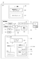
図1は、本実施形態に係る印刷システムを示す図である。本実施形態に係る印刷システムは、PC111とMFP100で構成される。
<First Embodiment>
FIG. 1 is a diagram illustrating a printing system according to the present embodiment. The printing system according to this embodiment includes a PC 111 and an
本実施形態に係るMFP(Multi Functional Peripheral)100は、制御装置110、リーダ部200、プリンタ部300を有する。なお、本実施形態では、MFPを例に説明するが、プリンタ部300による印刷機能があれば、SFP(Sigle Functional Peripheral)であってもよい。リーダ部200、制御装置110、プリンタ部300は電気的に接続されており、互いに制御コマンドやデータを送受する。また、MFP100には、フィニッシャ500を接続することができる。
An MFP (Multi Functional Peripheral) 100 according to the present embodiment includes a
制御装置110は、CPU120、画像メモリ130、不揮発性メモリ140、RAM150、ROM160、操作部170、タイマ180を有する。
The
CPU120は、ROM160に記憶されたプログラムをRAM150に読み出して実行することによってMFP100を統括的に制御する。
RAM150は、CPU120の作業領域として機能し、各種プログラムやデータを記憶する。
The
ROM160は、CPU120によって読みだされ、実行される各種プログラムを記憶しておく。
The
画像メモリ130は、画像データを記憶するメモリである。例えば、リーダ装置200によって読み取られた画像データを記憶する。また、画像メモリ130は、PC111から受信した画像データを記憶する。画像メモリ130に記憶された画像データは、CPU120からの指示によってプリンタ装置300に送られる。
The
不揮発性メモリ140は、各種プログラムや画像データを記憶する大容量のメモリである。なお、本実施形態では、不揮発性メモリ140の例としてHDDを例に説明するが、その他、ブルーレイディスク等、画像データを記憶するために十分な容量のメモリを持つものであればよい。
The
操作部170は、表示部とハードキーとを有する。表示部は、液晶表示部と当該液晶表示部に貼り付けられたタッチパネルシートとで構成され、液晶表示部には操作画面やMFP100の状態が表示される。操作部170は、当該操作画面またはハードキーを介してユーザの操作を受け付ける。なお、操作部170の全てのキーがソフトキーで構成されていてもよい。
The
タイマ180は、時間を計測するために用いられる。
The
ネットワークI/F190は、MFP100がPC111等の外部装置とネットワーク112を介して通信を行うための制御を行う。ここでは、外部装置としてPC111を例に挙げて説明するが、外部装置は他のMFPや携帯端末、ファクシミリ装置であってもよい。また、本実施形態では、MFP100と外部装置がネットワーク112を介して接続される例を説明するが、MFP100と外部装置はUSBケーブルを介して接続されてもよい。また、MFP100と外部装置は無線通信によって通信できるように構成されてもよい。
The network I /
リーダ部200は、原稿の画像を読み取り、読み取った画像を示す画像データを生成するスキャナユニット210と、スキャナユニット210によって読み取られる原稿を搬送するための原稿搬送ユニット(DFユニット)250を有する。
The
プリンタ部300は、シート(記録紙)に画像を印刷するユニットである。プリンタ部300は、給紙ユニット310に収納されたシートを1枚ずつ給紙し、マーキングユニット320に搬送する。給紙ユニット310には、カセット311〜314や手差しトレイ315が含まれる。カセット311〜314は、それぞれのカセット内にシートがあるか否かを検知するためのセンサを備える。手差しトレイ315も、手差しトレイ315にセットされたシートがあるか否かを検知するためのセンサを備える。
The
マーキングユニット320は、画像メモリ130から送られた画像データに基づいて、給紙されたシートに画像を印刷する。そして、プリンタ部300は、画像が印刷されたシートを、排紙ユニット330に排出する。なお、マーキングユニット320は、電子写真方式であっても、インクジェット方式であってもよい。また、画像を印刷することができるものであれば、その他の方法であってもよい。
The marking
次に、図1で説明したMFP100の詳細を図2を用いて説明する。
Next, details of the
リーダ部200における原稿給紙ユニット250は、原稿台にセットされた原稿を1枚ずつ給紙し、光学ユニット213まで搬送する。光学ユニット213まで搬送された原稿は排出トレイ219に排紙される。
A
原稿が光学ユニット213の上まで搬送されると、リーダ部200は、ランプ212を点灯し、光学ユニット213によって原稿に光を当てる。この時、原稿からの反射光は、ミラー214、215、216及びレンズ217によってCCDイメージセンサ(以下CCDという)218へ導かれる。そして、原稿の画像はCCD218によって読み取られる。CCD218から出力される画像データは、所定の処理が施された後、制御装置110へ転送される。
When the document is conveyed onto the
また、リーダ部200は、原稿給紙ユニット250とプラテンガラス211の間に置かれた原稿の画像を読み取る。その場合、リーダ部200は、ランプ212を点灯し、光学ユニット213を移動させる。この時の原稿からの反射光は、ミラー214、215、216及びレンズ217によってCCDイメージセンサ(以下CCDという)218へ導かれる。そして、原稿の画像はCCD218によって読み取られる。CCD218から出力される画像データは、所定の処理が施された後、制御装置110へ転送される。
In addition, the
プリンタ部300において、レーザドライバ321はレーザ発光部322を駆動するものであり、制御装置110の画像メモリ130から出力された画像データに応じたレーザ光をレーザ発光部322に発光させる。このレーザ光は感光ドラム323に照射され、感光ドラム323にはレーザ光に応じた潜像が形成される。この感光ドラム323の潜像の部分には現像器324によって現像剤が付着される。
In the
また、プリンタ部300は、給紙ユニット310として、引き出し状の形状のカセット311〜314、及び手差しトレイ315を有している。カセット311〜314は、それぞれにシートがセットされているか否かを検知するためのセンサ380を備える。また、手差しトレイ315は、手差しトレイ315にシートがセットされているか否かを検知するためのセンサ390を備える。
In addition, the
プリンタ部300は、カセット311〜314、及び手差しトレイ315のいずれかからシートを給紙し、転写部325へ搬送路331を通して搬送する。転写部325は、感光ドラム323に付着された現像剤をシートに転写する。
The
現像剤が転写されたシートは搬送ベルト326によって、定着部327に搬送される。定着部327は、熱と圧力により現像剤をシートに定着する。その後、定着部327を通過したシートは、搬送路335、搬送路334を通り排出される。シートの印字面を反転して排出する場合、シートは、搬送路336を通して搬送路338まで導かれる。そこからシートは、逆方向に搬送され、搬送路337、搬送路334を通して搬送可能である。
The sheet onto which the developer has been transferred is conveyed to the fixing
また、両面印刷が設定されている場合、シートは、定着部327を通過したあと、搬送路336を通って、フラッパ329によって搬送路333に導かれる。その後、シートは逆方向に搬送され、フラッパ329によって、搬送路338に導かれた後、再給紙搬送路332に導かれる。再給紙搬送路332に導かれたシートは、上述したタイミングで搬送路331を通り、転写部325まで搬送され、転写部325によってシートの第2面に現像剤が転写される。そして、シートは、定着部327を通して搬送路334に導かれる。
When duplex printing is set, the sheet passes through the fixing
片面印刷であるか、両面印刷であるかにかかわらず、搬送路334を通して搬送されたシートはフィニッシャ部500へ搬送される。
Regardless of single-sided printing or double-sided printing, the sheet conveyed through the
搬送されたシートは、まずバッファユニット501に送られる。ここでは、場合に応じて搬送されてきたシートを、バッファローラに巻きつけてバッファリングする。例えば、この下流で行われるステイプル等処理に時間がかかる場合は、このバッファユニットを利用することによって本体から搬送されてくるシートの搬送間隔を調整することができる。
The conveyed sheet is first sent to the
そして、シートは、この後、上流排出ローラ対502、下流排出ローラ対503によって搬送路504を経由し、スタックトレイ505に積まれる。スタックトレイ505に1部数のシート束が積載されたら、積載されたシート束は排紙トレイ507に排出される。
After that, the sheet is stacked on the
シフトするよう指定されている場合、スタックトレイ505に積載されたシートの束を、直前に排紙したシートの束に対してずらし、排出トレイ507に排出することによって部の切れ目が、ユーザにとってわかりやすくなる。
When it is designated to shift, the sheet stack stacked on the
ステイプルするよう指定されている場合、上流排出ローラ対502で搬送され、下流排出ローラ対503によって搬送路504を経由して、スタックトレイ505に積まれたシート束に対してステイプルユニット506によってステイプル処理が行われる。綴じられたシート束は、下流排出ローラ対503により排出トレイ507に排出される。
When stapling is specified, the
次に、図3を用いて、図1に示したMFP100が有する操作部170について説明する。
Next, the
操作部170は、ハードキーによるユーザ操作を受付けるキー入力部601、ソフトキー(表示キー)を表示可能で、当該ソフトキーによるユーザ操作を受付けるタッチパネル部602を有する。
The
まず、キー入力部601について説明する。図2に示すように、キー入力部601は、操作部電源スイッチ603を備える。MFP100が、スタンバイモード(通常動作状態)のときに、操作部電源スイッチ603がユーザによって押されると、CPU120は、MFP100を、スタンバイモードからスリープモード(消費電力を抑えている状態)に切り替える。一方、MFP100が、スリープモードのときに、操作部電源スイッチ603がユーザによって押されると、CPU120は、MFP100を、スリープモードからスタンバイモードに切り替える。
First, the
スタートキー605は、コピーや、データの送信を、MFP100に実行させる指示をユーザから受付けるためのキーである。
A
ストップキー604は、コピーや、データの送信を中断する指示をユーザから受付けるためのキーである。
A
テンキー606は、各種設定の置数の設定をユーザにより実行するためのキーである。
A
次に、タッチパネル部602について説明する。タッチパネル部602は、LCD(Liquid Crystal Display:液晶表示部)と、その上に貼られた透明電極からなるタッチパネルシートとを有する。このタッチパネル部602は、ユーザからの各種設定を受付ける機能と、ユーザに情報を提示する機能とを有する。
Next, the
以上の構成を有するMFP100は、複数種類のジョブを実行することができる。
例えば、MFP100は、リーダ部200によって原稿の画像を読み取り、読み取った原稿の画像を示す画像データを生成し、当該画像データと操作部170を介して受け付けた設定に基づいてシートに画像を印刷させるコピージョブを実行する。
For example, the
また、MFP100は、PC111から受信した印刷データを解析し、PC111から受け付けた印刷設定に基づいて画像データを生成し、生成した画像データに基づいてシートに画像を印刷させるプリントジョブを実行する。
Further, the
さらに、MFP100は、電話回線を介して外部のファクシミリ装置からコードデータを受信し、受信したコードデータを画像データに変換し、変換された画像データに基づいてシートに画像を印刷するファクスプリントジョブを実行する。
Further,
ここでは、MFP100が、複数種類のジョブを実行することについて説明したが、本発明はこれに限らない。MFP100は、これらの複数種類のジョブのうちの一部のジョブを実行できるものであればよい。
Although the description has been given here of the case where the
そして、MFP100は、封筒に画像を印刷することができる。ユーザは、手差しトレイ315に封筒をセットし、操作部170を介して封筒の設定を行い、MFP100にコピージョブやプリントジョブを実行させることによって、封筒に画像を印刷させることができる。
Then, the
以下に、手差しトレイ315に封筒をセットしてから、印刷を実行するまでの制御例を説明する。
Hereinafter, a control example from when an envelope is set on the
図4は、手差しトレイ315を上から見た図である。搬送方向607は、手差しトレイ315に載置されたシートが印刷時にMFP100のプリンタ部300によって給紙される方向を示す。方向641は主走査方向を示し、方向642は副走査方向を示す。また、本実施形態では、MFP100の正面(図2のMFP100の手前側)にユーザが立った時に奥になる方向を奥方向643と定義し、手前になる方向を手前方向644と定義する。
FIG. 4 is a view of the
図4に示す例では、封筒が、フラップを開いた状態で手差しトレイ315に載置されている。ユーザは、手差しトレイ315のガイド601を奥方向615または手前方向616に動かし、手差しトレイ315に載置された封筒の上端に合わせる。このとき、ガイド602も、ガイド601に連動して移動する。
In the example shown in FIG. 4, the envelope is placed on the
このように連動するガイド601及びガイド602によって手差しトレイ315にセットされた封筒を固定し、封筒を給紙するときに、封筒の斜行を抑えることができる。
The envelope set in the
手差トレイ315に用紙がセットされたことを図1に示したセンサ390で検知すると、CPU120は、図5のフローチャートに示す処理を開始する。なお、図5のフローチャートの各処理は、CPU120が、ROM160に記憶されたプログラムを実行することによって実現される。
When the
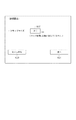
図5のS5001で、CPU120は、図7に示す用紙設定画面を操作部170に表示させる。
In S5001 of FIG. 5, the
図7に示す画面で、ユーザは、手差しトレイ315にセットした用紙のサイズを、複数のサイズの中から1つ選択する。定型サイズボタン608は、ユーザが、手差しトレイ315にA4サイズやB5サイズなどの定型サイズの用紙をセットしたときに押下するボタンである。ユーザ設定ボタン609は、ユーザが、手差しトレイ315に、不定型サイズの用紙をセットしたときに押下するボタンである。ユーザ設定ボタン609が押された場合、ユーザは、手差しトレイ315にセットしたシートの縦と横の長さを設定する。封筒ボタン610は、ユーザが、手差しトレイ315に、封筒をセットしたときに押下するボタンである。
In the screen illustrated in FIG. 7, the user selects one of a plurality of sizes as the size of the paper set on the
S5002で、CPU120は、封筒ボタン610が押されたか否かを判定する。封筒ボタン610が押されたと判定した場合、S5003に処理を進め、定型サイズボタン608やユーザ設定ボタン609が押された場合、S5009に処理を進める。定型サイズボタン608が押された場合、S5009で、CPU120は、手差しトレイ315にセットされたシートのサイズとして、押された定型サイズボタン608が示すサイズをRAM150に保存して処理を終了する。一方、ユーザ設定ボタン609が押された場合、CPU120は、手差しトレイ315にセットされたシートのサイズとして、ユーザによって設定されたシートの縦と横の長さをRAM150に保存して終了する。ここでRAM150に保存されたサイズは、プリンタ部300による画像の印刷に用いられる。
In S5002,
一方、S5002で封筒ボタン610が押されたと判定し、S5003に処理を進めた場合、CPU120は、操作部170に、図8の画面を表示させる。
On the other hand, when determining that the
S5004〜S5006で、封筒サイズの設定、坪量の設定、フラップ位置の設定を行う。ユーザは、図8の画面を介して、手差しトレイ315にセットした封筒の設定を行う。
In S5004 to S5006, the envelope size, basis weight, and flap position are set. The user sets the envelope set on the
図8の領域1001と領域1002は、封筒のサイズをユーザから受け付けるための領域である。領域1001は、封筒のフラップを天としたときの縦方向の長さであり、領域1002は、封筒のフラップを天としたときの横方向の長さである。ユーザは、領域1001にタッチし、テンキー606を使って封筒の縦の長さを示す数値を入力する。また、ユーザは、領域1002にタッチし、テンキー606を使って横の長さを示す数値を入力する。CPU120は、受け付けた数値を、封筒の縦の長さと横の長さとしてRAM150に保存する。
An
領域1003は、封筒の坪量をユーザから受け付けるための領域である。ユーザは、領域1003にタッチし、テンキー606を操作して封筒の坪量を示す数値を入力する。CPU120は、受け付けた数値を、封筒の坪量としてRAM150に保存する。坪量の設定は、封筒に画像を印刷する際の定着部327の温度や、封筒の搬送速度を決めるために用いられる。
An
先端ボタン1004、奥ボタン1005、後端ボタン1006は、手差しトレイ315にセットされた封筒のフラップの位置を受け付けるためのボタンである。先端ボタン1004は、手差しトレイ315に、封筒を、封筒のフラップの位置が搬送方向先端にくるようにセットした場合に押下されるボタンであり、封筒のフラップを閉じた状態で封筒をセットするときに用いられる。奥ボタン1005は、手差しトレイ315に、封筒を、図10に示すように、封筒のフラップの位置が奥側にくるようにセットした場合に押下されるボタンである。後端ボタン1006は、手差しトレイ315に、封筒を、封筒のフラップの位置が搬送方向後端にくるようにセットした場合に押下されるボタンであり、封筒のフラップを閉じた状態で封筒をセットするときに用いられる。
A leading
キャンセルボタン1020は、図8を介して受け付けた設定を反映せずに、図5に示す画面に表示を戻すボタンである。次へボタン1021は、図8を介して受け付けた設定を確定させて、次の画面に表示を進めるためのボタンである。なお、ここで受け付けた設定は、プリンタ部300による印刷に利用され、印刷が完了するまで、手差しトレイ315にセットされた封筒の情報としてRAM150に保持される。
The cancel
ここでは、S5004、S5005、S5006の順で設定を受け付ける例を説明したが、設定を受け付ける順はこれに限らず、ユーザは、封筒のサイズと封筒の坪量とフラップ位置を任意の順に設定できる。 Here, the example in which the settings are received in the order of S5004, S5005, and S5006 has been described. However, the order in which the settings are received is not limited to this, and the user can set the envelope size, the envelope basis weight, and the flap position in any order. .
次に、S5004〜S5006までの処理が終わり、次へボタン1011が押されると、CPU120は、S5007に処理を進め、フラップサイズの設定を行う。
Next, when the processing from S5004 to S5006 ends and the
このS5007の処理について、図6を用いて説明する。 The process of S5007 will be described with reference to FIG.
まず、S5011で、CPU120は、S5006で受け付けたフラップの位置が奥であるか否かを判定する。フラップの位置が搬送方向先端または搬送方向後端であると判定された場合、S5012に処理を進め、フラップの位置が奥であると判定した場合、S5014に処理を進める。
First, in S5011, the
S5012に処理を進めた場合、CPU120は、封筒のフラップサイズを0mmに決定し、S5013で、0mmを封筒のフラップサイズとしてRAM150に記憶する。そして、封筒の設定処理を終了する。
When the process has proceeded to S5012, the
一方、S5014に処理を進めた場合、CPU120は、封筒のフラップサイズを設定するための図9に示す画面を操作部170に表示させる。図9に示す画面の領域1007は、封筒のフラップサイズを受け付けるための領域である。ユーザは、領域1007をタッチし、テンキー606を操作して封筒のフラップサイズを示す数値を入力する。S5015で、CPU120は、ユーザによって入力されたフラップサイズを示す数値を受け付ける。そして、次へキー1021が押されると、S5016で、CPU120は、受け付けた数値を、封筒のフラップサイズとしてRAM150に保存し、封筒の設定処理を終了する。なお、キャンセルキー1020が押されると、受け付けた数値を破棄し、CPU120は、図8に示す画面を操作部170に表示させる。
On the other hand, when the process has proceeded to S5014, the
ここで、フラップの位置が奥である場合に限って、ユーザに封筒のフラップサイズを入力させる理由を説明する。フラップの位置が奥である場合、封筒は手差しトレイ315に、図10に示すような状態でセットされている。ここで、画像をフラップの長さ608だけシフトして印刷しなければ、画像がフラップにまで印刷されてしまう。そこで、封筒のフラップが奥になるようにセットされている場合、CPU120は、画像をシフトすべき長さを特定するために、図9に示す画面の領域1007でユーザに設定させるのである。
Here, the reason why the user inputs the flap size of the envelope only when the position of the flap is at the back will be described. When the flap is at the back, the envelope is set on the
一方、フラップの位置が搬送方向先端の場合、フラップは閉じられた状態でセットされており、封筒に印刷すべき画像をシフトする必要がない。そのため、封筒のフラップサイズを0mmと決定しているのである。また、フラップの位置が搬送方向後端の場合、フラップは開かれた状態でセットされるが、封筒に印刷すべき画像をシフトする必要がない。そのため、封筒のフラップサイズを0mmと決定しているのである。 On the other hand, when the flap position is the leading end in the transport direction, the flap is set in a closed state, and there is no need to shift the image to be printed on the envelope. Therefore, the flap size of the envelope is determined to be 0 mm. When the flap is at the rear end in the transport direction, the flap is set in an open state, but there is no need to shift the image to be printed on the envelope. Therefore, the flap size of the envelope is determined to be 0 mm.
次に、以上のような封筒の設定を行った後に、MFP100が封筒に画像を印刷する制御を、図11を用いて説明する。なお、図11のフローチャートの各処理は、CPU120が、ROM160に記憶されたプログラムを実行することによって実現される。
Next, a control for printing an image on the envelope after
S2001で、CPU120は、ジョブを受け付ける。ここではジョブの例として、上述したプリントジョブを例に挙げて説明する。CPU120は、プリントジョブを解析し、プリントジョブを実行することによって印刷すべき画像を画像メモリ130に記憶する。また、プリントジョブで設定された印刷設定をRAM150に記憶する。
In step S2001, the
S2002で、CPU120は、プリントジョブを実行することによって印刷すべき画像の天の位置が、封筒の天の位置と一致するか否かを判定する。ここで印刷すべき画像の天を示す情報は、PC111のアプリケーションソフトまたはプリンタドライバで指定され、印刷設定に付与されている。一方、封筒の天の位置は、S5006で指定されたフラップの位置と同じである。そして、S2002で印刷すべき画像の天の位置が、指定された封筒の天の位置と一致しないという判定された場合、CPU120は、画像を回転するためにS2003に処理を進める。一方、印刷すべき画像の天の位置が、指定された封筒の天の位置と一致するという判定の結果が得られた場合、画像を回転する必要がないため、CPU120は、S2003をスキップしてS2004に処理を進める。通常、印刷設定では、手差しトレイ315の奥方向642が画像の天になるように指定されているので、本実施形態では、画像の天が手差しトレイ315の奥方向642が画像の天になるように指定されている場合を例に説明する。印刷設定で、手差しトレイ315の奥方向642が画像の天になるように指定されている場合、S2002で、CPU120は、指定された封筒のフラップの位置が「奥」であるか否かを判定する。CPU120は、指定されたフラップの位置が「奥」であると判定した場合、画像を回転する必要がないと判断し、S2004に処理を進める。一方、CPU120は、指定されたフラップの位置が「奥」でないと判定した場合、S2003に処理を進める。
In step S2002, the
ここで、S2003の詳細について、図12を用いて説明する。図12に示す各ステップの処理は、CPU120が、ROM160内に記憶されたプログラムを読み出して実行することによって行われる。
Here, the details of S2003 will be described with reference to FIG. The processing of each step shown in FIG. 12 is performed by the
S3002で、CPU120は、指定されたフラップの位置が「搬送方向後端」であるか否かを判定する。「搬送方向後端」であると判定した場合、S3003に処理を進め、「搬送方向後端」ではないと判定した場合、つまり「搬送方向先端」である場合、S3004に処理を進める。
In S3002, the
S3003に処理を進めた場合、CPU120は、画像を時計周りに90度回転し、図11のS2004に処理を進める。
When the process has proceeded to S3003, the
S3004に処理を進めた場合、CPU120は、画像を時計周りに270度回転し、図11のS2004に処理を進める。なお、画像を反時計周りに90度回転するようにしてもよい。
When the process has proceeded to S3004, the
図11に説明を戻す。S2004で、CPU120は、指定されたフラップの位置が「奥」であるか否かを判定する。「奥」であると判定した場合、S2005に処理を進め、「奥」ではないと判定した場合、S2007に処理を進める。
Returning to FIG. In step S2004, the
S2005で、CPU120は、手差しトレイ315にセットされた封筒のフラップが開かれているか、閉じているかを判定する。ここで、CPU120は、RAM150に保存されているフラップのサイズに基づいて封筒のフラップが開かれているか、閉じているかを判定する。RAM150に保存されているフラップのサイズが0mmではない場合、フラップは開いていると判定し、0mmである場合、フラップは開いていると判定する。フラップが開かれていると判定した場合、S2006に処理を進め、フラップが閉じていると判定した場合、S2006の処理を実行せずに、S2007に処理を進める。
In step S2005, the
S2006で、CPU120は、指定されたフラップの長さだけ、画像メモリ130に記憶された画像をシフトする。このシフトは、図10の手前方向644に、指定されたフラップの長さだけ画像がずれた状態で印刷するために行われる。
In step S2006, the
S2007で、CPU120は、画像メモリ130に記憶された画像をプリンタ部300に送信し、プリンタ部300に対して画像を印刷するよう指示する。
In step S2007, the
プリンタ部300は、その指示を受け付けると、給紙ユニット310からシートを給紙し、画像メモリ130に記憶された画像データに基づいてマーキングユニット320によって画像を印刷する。プリンタ部300は、画像が印刷されたシートを、排紙ユニット330に排紙する。
Upon receiving the instruction, the
以上のように制御することで、手差しトレイ315に、フラップが開いている状態で封筒をセットして印刷する場合も、フラップが閉じている状態で封筒をセットして印刷する場合も、封筒の正しい位置に正しい向きで画像を印刷することができる。そのため、ユーザは、フラップが閉じている状態で売られている封筒のフラップを、手差しトレイ315にセットする前に開くという作業をしなくて済む。
By controlling as described above, whether the envelope is set and printed on the
<第2の実施形態>
第1の実施形態では、フラップのサイズより先にフラップの位置を指定する場合を説明した。
<Second Embodiment>
In the first embodiment, the case where the flap position is specified before the flap size has been described.
第2の実施形態では、フラップの位置より先にフラップのサイズを指定する例について説明する。フラップのサイズが先に指定されると、フラップのサイズが0mmであるか否かが決定されるので、手差しトレイ315に、フラップが開いた状態で封筒がセットされるか、フラップが閉じた状態で封筒がセットされるかも決まる。
In the second embodiment, an example in which the flap size is specified before the flap position will be described. When the flap size is specified first, it is determined whether or not the flap size is 0 mm. Therefore, the envelope is set on the
ここで、フラップが開いた状態の封筒に画像を印刷する場合には、封筒の搬送中にフラップが引っ掛からないように、封筒のフラップが搬送方向後端になるようにセットすることが好ましい。一方、フラップが閉じた状態の封筒に画像を印刷する場合には、封筒のフラップが搬送方向先端になるようにセットすることが好ましい。 Here, when printing an image on an envelope with the flap opened, it is preferable to set the envelope so that the flap is at the rear end in the transport direction so that the flap is not caught during the transport of the envelope. On the other hand, when printing an image on an envelope with the flap closed, it is preferable to set the envelope so that the flap of the envelope is at the leading end in the transport direction.
第2の実施形態では、そのような事情に鑑みて、先に指定されたフラップの開閉状態に応じて、封筒をセットできない向きをユーザが認識することができる例を説明する。それによって誤った向きで封筒が手差しトレイ315にセットされ、MFP100内でジャムが発生してしまう可能性を軽減することができる。
In the second embodiment, in view of such circumstances, an example will be described in which the user can recognize the direction in which the envelope cannot be set in accordance with the flap opening / closing state specified previously. As a result, the possibility that the envelope is set in the
MFP100の構成などについては、第1の実施形態と同様であるため、詳しい説明を省略し、差分を説明する。
Since the configuration of the
第2の実施形態では、手差しトレイ315にセットされた封筒の設定として、図5に示すフローチャートの代わりに、CPU120は、図13に示すフローチャートを実行する。図5の処理と同じ処理については、同じ符号を付けている。図5との差分は、S8001〜とS8005である。図13のフローチャートの各処理は、CPU120が、ROM160内に記憶されたプログラムを読み出して実行することによって行われる。
In the second embodiment, as the setting of the envelope set on the
第2の実施形態では、図6に示す封筒ボタン610が押された場合に、S8001で、CPU120は、図8に示す画面の代わりに、図15に示す画面を操作部170に表示させる。
In the second embodiment, when the
図15に示す操作画面には、図8と同様に、封筒のサイズを設定するための領域1001及び1002、封筒の坪量を設定するための領域1003が表示されている。
The operation screen shown in FIG. 15
図15に示す画面が図8に示す画面と異なるのは、フラップの位置の指定の代わりに、フラップのサイズを指定する領域4001が表示されている点である。S8002〜S8004で、CPU120は、ユーザから、封筒のサイズの設定、封筒の坪量の設定、封筒のフラップサイズの設定を受け付ける。封筒のフラップサイズに関して、ユーザは、領域4001をタッチし、テンキー606を操作して封筒のフラップサイズを示す数値を入力する。CPU120は、ユーザによって入力されたフラップサイズを示す数値を受け付ける。そして、CPU120は、受け付けた数値を、封筒のフラップサイズとしてRAM150に保存し、封筒の設定処理を終了する。
The screen shown in FIG. 15 is different from the screen shown in FIG. 8 in that an area 4001 for specifying the flap size is displayed instead of specifying the flap position. In steps S8002 to S8004, the
次へボタン1011が押されると、CPU120は、S8005に処理を進める。S8005の処理の詳細を図14を用いて説明する。図14に示す各ステップの処理は、CPU120が、ROM160内に記憶されたプログラムを読み出して実行することによって行われる。
When the
次に、S8010で、CPU120は、S8004で設定されたフラップのサイズとして0mmが設定されているか否かを判定する。フラップのサイズとして0mmが設定されていると判定した場合、S8011に処理を進め、フラップのサイズとして0mm以外の値が設定されている場合、S8013に処理を進める。
In step S8010, the
S8011で、CPU120は、図16(a)に示すフラップ位置設定画面を操作部170に表示させる。
In step S8011, the
図16(a)に示す画面では、フラップの位置を指定するためのボタンとして、先端ボタン4002、奥ボタン4003、後端ボタン4004が表示されている。ここで、CPU120は、封筒のフラップ位置として、先端ボタン4002による搬送方向先端の選択と、奥ボタン4003による奥が選択された場合、それぞれの位置をフラップの位置としてRAM150に保存する。一方、後端ボタン4004によって搬送方向後端が選択されても、搬送方向後端をフラップ位置としてRAM150に保存しない。また、図16(a)に示す画面は、ユーザが搬送方向後端を選択できないことを、後端ボタン4004がグレーアウトすることによって示している。そのため、ユーザは、この図16(a)に示す画面を見て、搬送方向後端を選択できないことを容易に認識し、封筒のフラップが搬送方向後端にくるように封筒をセットすべきでないことを容易に知ることができる。
In the screen shown in FIG. 16A, a
そして、S8012で、CPU120は、図16(a)に示す画面で受け付けたフラップ位置を、手差しトレイ315にセットされた封筒のフラップの位置としてRAM150に記憶し、処理を終了する。
In step S <b> 8012, the
一方、S8010からS8013に処理を進めた場合、CPU120は、図16(b)に示すフラップ位置設定画面を操作部170に表示させる。
On the other hand, when the processing proceeds from S8010 to S8013, the
図16(b)に示す画面では、フラップの位置を指定するためのボタンとして、先端ボタン4002、奥ボタン4003、後端ボタン4004が表示されている。ここで、CPU120は、封筒のフラップ位置として、奥ボタン4003による奥が選択された場合と、後端ボタン4004による搬送方向後端が選択された場合、それぞれの位置をフラップの位置としてRAM150に保存する。一方、先端ボタン4002によって搬送方向先端が選択されても、搬送方向先端をフラップ位置としてRAM150に保存しない。また、図16(b)に示す画面は、ユーザが搬送方向先端を選択できないことを、先端ボタン4002がグレーアウトすることによって示している。そのため、ユーザは、この図16(b)に示す画面を見て、搬送方向後端を選択できないことを容易に認識し、封筒のフラップが搬送方向先端にくるように封筒をセットすべきでないことを容易に知ることができる。
On the screen shown in FIG. 16B, a
そして、S8014で、CPU120は、図16(b)に示す画面で受け付けたフラップ位置を、手差しトレイ315にセットされた封筒のフラップの位置としてRAM150に記憶し、処理を終了する。
In step S <b> 8014, the
以降の処理は、第1の実施形態と同様であるため、詳しい説明を省略する。 Since the subsequent processing is the same as that of the first embodiment, detailed description thereof is omitted.
以上のような制御によって、ユーザは、先にフラップのサイズを指定した場合に、封筒を誤った向きで手差しトレイ315にセットしてしまい、MFP100内でジャムが発生してしまう可能性を軽減することができる。
With the above-described control, when the user previously specifies the flap size, the envelope is set on the
なお、本実施形態では、先に指定されたフラップの開閉状態に応じて、指定できないフラップの位置をユーザに見せることによって、ユーザは、封筒を手差しトレイ315にセットする際に、セットすべきでない封筒の向きを認識する例を説明した。しかしながら、本発明はこれに限らず、メッセージによって、セットすべきでない封筒の向きをユーザに通知しても良い。具体的には、封筒のフラップサイズが0mmではなく、封筒を開いた状態で手差しトレイ315に保持させる場合に、封筒のフラップの位置が封筒の搬送方向先端にくるように封筒をセットすべきでないことを示すメッセージを表示してユーザに通知すればよい。また、封筒のフラップサイズが0mmであり、封筒のフラップを閉じた状態で手差しトレイ315に保持させる場合に、封筒のフラップの位置が封筒の搬送方向後端にくるように封筒をセットすべきでないことを示すメッセージを表示してユーザに通知すればよい。
In this embodiment, the user should not set the envelope when setting the envelope on the
<その他の実施形態>
上述した実施形態では、S2005で、ユーザによって設定され、RAM150に保存されたフラップのサイズが0mmではない場合、フラップは開いていると判定し、0mmである場合、フラップは開いていると判定する例を説明した。しかしながら、本発明はこれに限られない。例えば、フラップが開いた状態で封筒をセットするか、フラップが閉じた状態で封筒をセットするかを、ユーザが選択するようにしてもよい。その場合、フラップが開いていると設定された場合にのみ、フラップのサイズをCPU120が操作部170を介してユーザから受け付けるようにすればよい。
<Other embodiments>
In the above-described embodiment, if the size of the flap set by the user and stored in the
また、上述した実施形態では、フラップの位置として、搬送方向先端または奥または搬送方向後端をユーザに指定させる例を説明したが、これ以外の指定ができるようにしてもよい。例えば、搬送方向先端、奥、搬送方向後端に加えて、奥とは180度回転した方向である手前を、フラップの位置として指定できるようにしてもよい。ユーザによって手前が指定された場合、フラップの開閉状態によらずに、MFP100は、奥が天である画像を180度回転して印刷するよう制御すればよい。
In the above-described embodiment, the example in which the user designates the leading end or the back in the transport direction or the rear end in the transport direction as the flap position has been described. However, other designations may be made. For example, in addition to the front end in the transport direction, the back, and the rear end in the transport direction, the front, which is the direction rotated 180 degrees, may be designated as the flap position. When the front is designated by the user, the
上述した実施形態では、手差しトレイ315に封筒をセットして印刷する場合について説明したが、本発明は、カセット311〜314のいずれかから封筒を給紙して印刷するものに適用してもよい。ただし、手差しトレイ315に封筒をセットする場合と異なり、ユーザは、カセット311〜314のいずれかに封筒の印刷面がカセットの底の面に向くように封筒をセットする必要がある。
In the above-described embodiment, the case where envelopes are set on the
また、第1の実施形態、第2の実施形態では、操作部170を介して封筒の設定画面の表示を行い、ユーザから封筒の設定を受付制御する例を説明した。しかしながら、本発明は、これに限られない。上述した各種設定画面を、MFP100が、PC111の表示部に表示するよう制御し、PC111の操作部を介してユーザから受け付けた設定をMFP100が受信して制御してもよい。また、PC111のCPUが主体的に、上述した各種設定画面の表示と、設定の受け付けを行ってもよい。
Further, in the first embodiment and the second embodiment, the example in which the envelope setting screen is displayed via the
上述した実施形態では、プリントジョブを実行する場合を例に説明したが、コピージョブやファクスプリントジョブに適用してもよい。 In the above-described embodiment, the case where a print job is executed has been described as an example, but the present invention may be applied to a copy job or a fax print job.
本実施形態におけるフローチャートに示す機能は、ネットワーク又は各種記憶媒体を介して取得したソフトウエア(プログラム)をコンピュータパソコン等の処理装置(CPU、プロセッサ)にて実行することでも実現できる。 The functions shown in the flowchart in the present embodiment can also be realized by executing software (program) acquired via a network or various storage media by a processing device (CPU, processor) such as a computer personal computer.
120 CPU
150 RAM
160 ROM
120 CPU
150 RAM
160 ROM
Claims (6)
前記載置部から搬送されてきた前記封筒に画像を印刷する印刷部と、
前記載置部に載置される前記封筒のフラップの位置の選択をユーザから受け付ける操作部と、
前記操作部を用いてユーザに選択された前記封筒のフラップの位置に基づき画像の回転処理を実行し、前記回転処理がされた画像を前記封筒に印刷するよう前記印刷部を制御する制御部と、を備え、
前記封筒のフラップの位置は、
(1)前記封筒のフラップが、前記封筒の本体部分よりも搬送方向下流側に置かれる第1のフラップ位置、または、
(2)前記封筒のフラップが、前記封筒の本体部分よりも搬送方向上流側に置かれる第2のフラップ位置であり、
前記制御部は、フラップが開いた状態で前記封筒が前記載置部に載置される場合は前記第1のフラップ位置の選択を不可とし、フラップが閉じた状態で前記封筒が前記載置部に載置される場合は前記第2の位置の選択を不可とするよう前記操作部を制御することを特徴とする印刷装置。 A placement section on which the envelope is placed;
A printing unit for printing an image on the envelope conveyed from the placement unit;
An operation unit that receives a selection of a position of the flap of the envelope placed on the placement unit from a user;
A control unit that performs image rotation processing based on the flap position of the envelope selected by the user using the operation unit, and controls the printing unit to print the image subjected to the rotation processing on the envelope; With
The position of the envelope flap is:
(1) The first flap position where the flap of the envelope is placed on the downstream side in the transport direction from the main body portion of the envelope, or
(2) The flap of the envelope is a second flap position placed on the upstream side in the transport direction from the main body portion of the envelope,
The control unit makes the selection of the first flap position impossible when the envelope is placed on the placement unit with the flap opened, and the envelope is placed on the placement unit with the flap closed. When the printer is placed on the printer, the operation unit is controlled so that the second position cannot be selected.
(3)前記フラップと前記封筒の本体部分とが、前記搬送方向に直交する方向に並ぶ第3のフラップ位置を選択可能であり、
前記制御部は、前記封筒のフラップの開閉状態に関わらず前記第3の位置は選択可能とすることを特徴とする請求項1に記載の印刷装置。 In addition to (1) and (2) as the flap position of the envelope,
(3) The third flap position in which the flap and the main body portion of the envelope are arranged in a direction orthogonal to the transport direction can be selected.
The printing apparatus according to claim 1, wherein the control unit can select the third position regardless of an open / closed state of the flap of the envelope.
Priority Applications (3)
| Application Number | Priority Date | Filing Date | Title |
|---|---|---|---|
| JP2013153614A JP6296719B2 (en) | 2013-07-24 | 2013-07-24 | Printing apparatus, printing apparatus control method, and program |
| US14/336,358 US9288352B2 (en) | 2013-07-24 | 2014-07-21 | Printing apparatus that prints an image on an envelope |
| CN201410349849.XA CN104339876B (en) | 2013-07-24 | 2014-07-22 | Printing apparatus, control method of printing apparatus, and storage medium |
Applications Claiming Priority (1)
| Application Number | Priority Date | Filing Date | Title |
|---|---|---|---|
| JP2013153614A JP6296719B2 (en) | 2013-07-24 | 2013-07-24 | Printing apparatus, printing apparatus control method, and program |
Related Child Applications (1)
| Application Number | Title | Priority Date | Filing Date |
|---|---|---|---|
| JP2017245447A Division JP2018086844A (en) | 2017-12-21 | 2017-12-21 | Printer, control method for printer, and program |
Publications (3)
| Publication Number | Publication Date |
|---|---|
| JP2015024507A JP2015024507A (en) | 2015-02-05 |
| JP2015024507A5 JP2015024507A5 (en) | 2016-09-08 |
| JP6296719B2 true JP6296719B2 (en) | 2018-03-20 |
Family
ID=52390268
Family Applications (1)
| Application Number | Title | Priority Date | Filing Date |
|---|---|---|---|
| JP2013153614A Active JP6296719B2 (en) | 2013-07-24 | 2013-07-24 | Printing apparatus, printing apparatus control method, and program |
Country Status (3)
| Country | Link |
|---|---|
| US (1) | US9288352B2 (en) |
| JP (1) | JP6296719B2 (en) |
| CN (1) | CN104339876B (en) |
Families Citing this family (4)
| Publication number | Priority date | Publication date | Assignee | Title |
|---|---|---|---|---|
| JP2015168109A (en) * | 2014-03-05 | 2015-09-28 | キヤノン株式会社 | Image processing system and image processing method |
| JP6671989B2 (en) | 2016-01-29 | 2020-03-25 | キヤノン株式会社 | Printing apparatus for rotating image data, printing method, and program. |
| JP2018099840A (en) * | 2016-12-21 | 2018-06-28 | キヤノン株式会社 | Image formation apparatus, sheet feeding control method and program |
| JP7158939B2 (en) * | 2018-07-27 | 2022-10-24 | キヤノン株式会社 | Image forming apparatus and image forming system |
Family Cites Families (12)
| Publication number | Priority date | Publication date | Assignee | Title |
|---|---|---|---|---|
| CN1180333A (en) | 1996-02-08 | 1998-04-29 | 普林斯特公司 | Printing and post-processing system and method of controlling the same |
| US5912695A (en) * | 1997-12-12 | 1999-06-15 | Pitney Bowes Inc. | System for printing pairs of envelopes or the like |
| CN2506457Y (en) | 2001-09-14 | 2002-08-21 | 徐平 | Printing and packaging integrated machine |
| JP4298409B2 (en) | 2003-08-07 | 2009-07-22 | キヤノン株式会社 | Information processing apparatus, printing method, and program |
| JP2009143682A (en) * | 2007-12-14 | 2009-07-02 | Murata Mach Ltd | Image forming device |
| CN201151240Y (en) | 2007-12-26 | 2008-11-19 | 杭州日新邮电设备有限公司 | Improved ink jet printer for envelope |
| JP6106915B2 (en) * | 2011-01-17 | 2017-04-05 | コニカミノルタ株式会社 | Image forming apparatus, image forming method, and program |
| JP5845586B2 (en) * | 2011-02-07 | 2016-01-20 | 富士ゼロックス株式会社 | Image processing apparatus and program |
| DE102011004344A1 (en) * | 2011-02-17 | 2012-08-23 | Böwe Systec Gmbh | Filling station and method for filling an envelope |
| JP6041482B2 (en) * | 2011-12-01 | 2016-12-07 | キヤノン株式会社 | Printing apparatus, control method therefor, and program |
| JP5852440B2 (en) * | 2011-12-28 | 2016-02-03 | キヤノン株式会社 | Printing apparatus, control method therefor, and program |
| US8544837B2 (en) | 2011-12-30 | 2013-10-01 | Pitney Bowes Inc. | Vacuum roller assembly |
-
2013
- 2013-07-24 JP JP2013153614A patent/JP6296719B2/en active Active
-
2014
- 2014-07-21 US US14/336,358 patent/US9288352B2/en active Active
- 2014-07-22 CN CN201410349849.XA patent/CN104339876B/en active Active
Also Published As
| Publication number | Publication date |
|---|---|
| CN104339876B (en) | 2017-04-12 |
| US20150029521A1 (en) | 2015-01-29 |
| CN104339876A (en) | 2015-02-11 |
| US9288352B2 (en) | 2016-03-15 |
| JP2015024507A (en) | 2015-02-05 |
Similar Documents
| Publication | Publication Date | Title |
|---|---|---|
| JP6218485B2 (en) | Printing apparatus, printing apparatus control method, and program | |
| US8072619B2 (en) | Printing apparatus and method for controlling the same | |
| JP6032990B2 (en) | Image forming apparatus, image forming apparatus control method, and program | |
| US11457115B2 (en) | Image reading apparatus and method for notifying user of possibility that documents with different sizes are mixed and read, and providing navigation for prompting enabling function and re-reading of documents | |
| US9516182B2 (en) | Image forming apparatus that enhances operability on screen displayed as split screens | |
| US10663904B2 (en) | Image forming apparatus | |
| JP6296719B2 (en) | Printing apparatus, printing apparatus control method, and program | |
| JP2010128364A (en) | Image forming apparatus | |
| JP2023134845A (en) | Sheet feeding device, image reading device and image forming device | |
| US7536149B2 (en) | Image forming apparatus | |
| US9843700B2 (en) | Image forming apparatus and method for controlling image forming apparatus | |
| JP2013252664A (en) | Printing apparatus, method for controlling the same, and program | |
| JP6007693B2 (en) | Image forming apparatus | |
| JP2018086844A (en) | Printer, control method for printer, and program | |
| JP2007076850A (en) | Image forming system equipped with sheet insertion device | |
| JP5286189B2 (en) | Image reading device | |
| JP3667177B2 (en) | Image forming apparatus | |
| JP2017219678A (en) | Image forming apparatus | |
| JP2007076851A (en) | Image forming system | |
| JP2013208821A (en) | Image forming apparatus system | |
| JP2012250463A (en) | Printing apparatus, and method for controlling printing apparatus, and program | |
| JP2005269173A (en) | Image forming apparatus | |
| JPH08181815A (en) | Image reader and image forming device | |
| JP2002027164A (en) | Facsimile terminal, its control method, and computer- readable storage medium for storing its control program | |
| JP2016158017A (en) | Image processing system and image processing method |
Legal Events
| Date | Code | Title | Description |
|---|---|---|---|
| A521 | Written amendment |
Free format text: JAPANESE INTERMEDIATE CODE: A523 Effective date: 20160722 |
|
| A621 | Written request for application examination |
Free format text: JAPANESE INTERMEDIATE CODE: A621 Effective date: 20160722 |
|
| A977 | Report on retrieval |
Free format text: JAPANESE INTERMEDIATE CODE: A971007 Effective date: 20170413 |
|
| A131 | Notification of reasons for refusal |
Free format text: JAPANESE INTERMEDIATE CODE: A131 Effective date: 20170516 |
|
| A521 | Written amendment |
Free format text: JAPANESE INTERMEDIATE CODE: A523 Effective date: 20170714 |
|
| A02 | Decision of refusal |
Free format text: JAPANESE INTERMEDIATE CODE: A02 Effective date: 20171003 |
|
| A521 | Written amendment |
Free format text: JAPANESE INTERMEDIATE CODE: A523 Effective date: 20171221 |
|
| A911 | Transfer of reconsideration by examiner before appeal (zenchi) |
Free format text: JAPANESE INTERMEDIATE CODE: A911 Effective date: 20171228 |
|
| TRDD | Decision of grant or rejection written | ||
| A01 | Written decision to grant a patent or to grant a registration (utility model) |
Free format text: JAPANESE INTERMEDIATE CODE: A01 Effective date: 20180123 |
|
| A61 | First payment of annual fees (during grant procedure) |
Free format text: JAPANESE INTERMEDIATE CODE: A61 Effective date: 20180220 |
|
| R151 | Written notification of patent or utility model registration |
Ref document number: 6296719 Country of ref document: JP Free format text: JAPANESE INTERMEDIATE CODE: R151 |