JP6032932B2 - Inkjet recording apparatus and recording data generation method - Google Patents
Inkjet recording apparatus and recording data generation method Download PDFInfo
- Publication number
- JP6032932B2 JP6032932B2 JP2012097899A JP2012097899A JP6032932B2 JP 6032932 B2 JP6032932 B2 JP 6032932B2 JP 2012097899 A JP2012097899 A JP 2012097899A JP 2012097899 A JP2012097899 A JP 2012097899A JP 6032932 B2 JP6032932 B2 JP 6032932B2
- Authority
- JP
- Japan
- Prior art keywords
- recording
- nozzle
- dot
- pixels
- recording head
- Prior art date
- Legal status (The legal status is an assumption and is not a legal conclusion. Google has not performed a legal analysis and makes no representation as to the accuracy of the status listed.)
- Active
Links
- 238000000034 method Methods 0.000 title claims description 93
- 238000009826 distribution Methods 0.000 claims description 79
- 230000015572 biosynthetic process Effects 0.000 claims description 7
- 239000000976 ink Substances 0.000 description 28
- 238000010586 diagram Methods 0.000 description 15
- 238000013139 quantization Methods 0.000 description 13
- 238000005304 joining Methods 0.000 description 11
- 238000006243 chemical reaction Methods 0.000 description 6
- 238000009792 diffusion process Methods 0.000 description 6
- 238000011156 evaluation Methods 0.000 description 6
- 238000003491 array Methods 0.000 description 4
- 238000003860 storage Methods 0.000 description 3
- 230000007723 transport mechanism Effects 0.000 description 3
- 239000003086 colorant Substances 0.000 description 2
- 230000000295 complement effect Effects 0.000 description 2
- 230000007547 defect Effects 0.000 description 1
- 230000007717 exclusion Effects 0.000 description 1
- 239000007788 liquid Substances 0.000 description 1
- 238000004519 manufacturing process Methods 0.000 description 1
- 230000000873 masking effect Effects 0.000 description 1
- 238000001454 recorded image Methods 0.000 description 1
- 238000000926 separation method Methods 0.000 description 1
Images


Classifications
-
- B—PERFORMING OPERATIONS; TRANSPORTING
- B41—PRINTING; LINING MACHINES; TYPEWRITERS; STAMPS
- B41J—TYPEWRITERS; SELECTIVE PRINTING MECHANISMS, i.e. MECHANISMS PRINTING OTHERWISE THAN FROM A FORME; CORRECTION OF TYPOGRAPHICAL ERRORS
- B41J2/00—Typewriters or selective printing mechanisms characterised by the printing or marking process for which they are designed
- B41J2/005—Typewriters or selective printing mechanisms characterised by the printing or marking process for which they are designed characterised by bringing liquid or particles selectively into contact with a printing material
- B41J2/01—Ink jet
- B41J2/015—Ink jet characterised by the jet generation process
- B41J2/04—Ink jet characterised by the jet generation process generating single droplets or particles on demand
- B41J2/045—Ink jet characterised by the jet generation process generating single droplets or particles on demand by pressure, e.g. electromechanical transducers
- B41J2/04501—Control methods or devices therefor, e.g. driver circuits, control circuits
- B41J2/0458—Control methods or devices therefor, e.g. driver circuits, control circuits controlling heads based on heating elements forming bubbles
-
- G—PHYSICS
- G06—COMPUTING; CALCULATING OR COUNTING
- G06K—GRAPHICAL DATA READING; PRESENTATION OF DATA; RECORD CARRIERS; HANDLING RECORD CARRIERS
- G06K15/00—Arrangements for producing a permanent visual presentation of the output data, e.g. computer output printers
- G06K15/02—Arrangements for producing a permanent visual presentation of the output data, e.g. computer output printers using printers
- G06K15/10—Arrangements for producing a permanent visual presentation of the output data, e.g. computer output printers using printers by matrix printers
- G06K15/102—Arrangements for producing a permanent visual presentation of the output data, e.g. computer output printers using printers by matrix printers using ink jet print heads
- G06K15/105—Multipass or interlaced printing
- G06K15/107—Mask selection
-
- B—PERFORMING OPERATIONS; TRANSPORTING
- B41—PRINTING; LINING MACHINES; TYPEWRITERS; STAMPS
- B41J—TYPEWRITERS; SELECTIVE PRINTING MECHANISMS, i.e. MECHANISMS PRINTING OTHERWISE THAN FROM A FORME; CORRECTION OF TYPOGRAPHICAL ERRORS
- B41J19/00—Character- or line-spacing mechanisms
- B41J19/18—Character-spacing or back-spacing mechanisms; Carriage return or release devices therefor
- B41J19/20—Positive-feed character-spacing mechanisms
- B41J19/202—Drive control means for carriage movement
-
- B—PERFORMING OPERATIONS; TRANSPORTING
- B41—PRINTING; LINING MACHINES; TYPEWRITERS; STAMPS
- B41J—TYPEWRITERS; SELECTIVE PRINTING MECHANISMS, i.e. MECHANISMS PRINTING OTHERWISE THAN FROM A FORME; CORRECTION OF TYPOGRAPHICAL ERRORS
- B41J2/00—Typewriters or selective printing mechanisms characterised by the printing or marking process for which they are designed
- B41J2/005—Typewriters or selective printing mechanisms characterised by the printing or marking process for which they are designed characterised by bringing liquid or particles selectively into contact with a printing material
- B41J2/01—Ink jet
- B41J2/015—Ink jet characterised by the jet generation process
- B41J2/04—Ink jet characterised by the jet generation process generating single droplets or particles on demand
- B41J2/045—Ink jet characterised by the jet generation process generating single droplets or particles on demand by pressure, e.g. electromechanical transducers
- B41J2/04501—Control methods or devices therefor, e.g. driver circuits, control circuits
- B41J2/04523—Control methods or devices therefor, e.g. driver circuits, control circuits reducing size of the apparatus
-
- B—PERFORMING OPERATIONS; TRANSPORTING
- B41—PRINTING; LINING MACHINES; TYPEWRITERS; STAMPS
- B41J—TYPEWRITERS; SELECTIVE PRINTING MECHANISMS, i.e. MECHANISMS PRINTING OTHERWISE THAN FROM A FORME; CORRECTION OF TYPOGRAPHICAL ERRORS
- B41J2/00—Typewriters or selective printing mechanisms characterised by the printing or marking process for which they are designed
- B41J2/005—Typewriters or selective printing mechanisms characterised by the printing or marking process for which they are designed characterised by bringing liquid or particles selectively into contact with a printing material
- B41J2/01—Ink jet
- B41J2/015—Ink jet characterised by the jet generation process
- B41J2/04—Ink jet characterised by the jet generation process generating single droplets or particles on demand
- B41J2/045—Ink jet characterised by the jet generation process generating single droplets or particles on demand by pressure, e.g. electromechanical transducers
- B41J2/04501—Control methods or devices therefor, e.g. driver circuits, control circuits
- B41J2/04525—Control methods or devices therefor, e.g. driver circuits, control circuits reducing occurrence of cross talk
-
- B—PERFORMING OPERATIONS; TRANSPORTING
- B41—PRINTING; LINING MACHINES; TYPEWRITERS; STAMPS
- B41J—TYPEWRITERS; SELECTIVE PRINTING MECHANISMS, i.e. MECHANISMS PRINTING OTHERWISE THAN FROM A FORME; CORRECTION OF TYPOGRAPHICAL ERRORS
- B41J2/00—Typewriters or selective printing mechanisms characterised by the printing or marking process for which they are designed
- B41J2/005—Typewriters or selective printing mechanisms characterised by the printing or marking process for which they are designed characterised by bringing liquid or particles selectively into contact with a printing material
- B41J2/01—Ink jet
- B41J2/135—Nozzles
- B41J2/145—Arrangement thereof
-
- B—PERFORMING OPERATIONS; TRANSPORTING
- B41—PRINTING; LINING MACHINES; TYPEWRITERS; STAMPS
- B41J—TYPEWRITERS; SELECTIVE PRINTING MECHANISMS, i.e. MECHANISMS PRINTING OTHERWISE THAN FROM A FORME; CORRECTION OF TYPOGRAPHICAL ERRORS
- B41J2/00—Typewriters or selective printing mechanisms characterised by the printing or marking process for which they are designed
- B41J2/005—Typewriters or selective printing mechanisms characterised by the printing or marking process for which they are designed characterised by bringing liquid or particles selectively into contact with a printing material
- B41J2/01—Ink jet
- B41J2/135—Nozzles
- B41J2/165—Prevention or detection of nozzle clogging, e.g. cleaning, capping or moistening for nozzles
- B41J2/16579—Detection means therefor, e.g. for nozzle clogging
-
- B—PERFORMING OPERATIONS; TRANSPORTING
- B41—PRINTING; LINING MACHINES; TYPEWRITERS; STAMPS
- B41J—TYPEWRITERS; SELECTIVE PRINTING MECHANISMS, i.e. MECHANISMS PRINTING OTHERWISE THAN FROM A FORME; CORRECTION OF TYPOGRAPHICAL ERRORS
- B41J2/00—Typewriters or selective printing mechanisms characterised by the printing or marking process for which they are designed
- B41J2/005—Typewriters or selective printing mechanisms characterised by the printing or marking process for which they are designed characterised by bringing liquid or particles selectively into contact with a printing material
- B41J2/01—Ink jet
- B41J2/205—Ink jet for printing a discrete number of tones
- B41J2/2054—Ink jet for printing a discrete number of tones by the variation of dot disposition or characteristics, e.g. dot number density, dot shape
-
- B—PERFORMING OPERATIONS; TRANSPORTING
- B41—PRINTING; LINING MACHINES; TYPEWRITERS; STAMPS
- B41J—TYPEWRITERS; SELECTIVE PRINTING MECHANISMS, i.e. MECHANISMS PRINTING OTHERWISE THAN FROM A FORME; CORRECTION OF TYPOGRAPHICAL ERRORS
- B41J2/00—Typewriters or selective printing mechanisms characterised by the printing or marking process for which they are designed
- B41J2/005—Typewriters or selective printing mechanisms characterised by the printing or marking process for which they are designed characterised by bringing liquid or particles selectively into contact with a printing material
- B41J2/01—Ink jet
- B41J2/21—Ink jet for multi-colour printing
- B41J2/2132—Print quality control characterised by dot disposition, e.g. for reducing white stripes or banding
-
- B—PERFORMING OPERATIONS; TRANSPORTING
- B41—PRINTING; LINING MACHINES; TYPEWRITERS; STAMPS
- B41J—TYPEWRITERS; SELECTIVE PRINTING MECHANISMS, i.e. MECHANISMS PRINTING OTHERWISE THAN FROM A FORME; CORRECTION OF TYPOGRAPHICAL ERRORS
- B41J25/00—Actions or mechanisms not otherwise provided for
- B41J25/001—Mechanisms for bodily moving print heads or carriages parallel to the paper surface
-
- B—PERFORMING OPERATIONS; TRANSPORTING
- B41—PRINTING; LINING MACHINES; TYPEWRITERS; STAMPS
- B41J—TYPEWRITERS; SELECTIVE PRINTING MECHANISMS, i.e. MECHANISMS PRINTING OTHERWISE THAN FROM A FORME; CORRECTION OF TYPOGRAPHICAL ERRORS
- B41J29/00—Details of, or accessories for, typewriters or selective printing mechanisms not otherwise provided for
- B41J29/38—Drives, motors, controls or automatic cut-off devices for the entire printing mechanism
- B41J29/393—Devices for controlling or analysing the entire machine ; Controlling or analysing mechanical parameters involving printing of test patterns
-
- G—PHYSICS
- G06—COMPUTING; CALCULATING OR COUNTING
- G06K—GRAPHICAL DATA READING; PRESENTATION OF DATA; RECORD CARRIERS; HANDLING RECORD CARRIERS
- G06K15/00—Arrangements for producing a permanent visual presentation of the output data, e.g. computer output printers
- G06K15/02—Arrangements for producing a permanent visual presentation of the output data, e.g. computer output printers using printers
- G06K15/10—Arrangements for producing a permanent visual presentation of the output data, e.g. computer output printers using printers by matrix printers
- G06K15/102—Arrangements for producing a permanent visual presentation of the output data, e.g. computer output printers using printers by matrix printers using ink jet print heads
-
- G—PHYSICS
- G06—COMPUTING; CALCULATING OR COUNTING
- G06K—GRAPHICAL DATA READING; PRESENTATION OF DATA; RECORD CARRIERS; HANDLING RECORD CARRIERS
- G06K2215/00—Arrangements for producing a permanent visual presentation of the output data
- G06K2215/111—Arrangements for producing a permanent visual presentation of the output data with overlapping swaths
Landscapes
- Engineering & Computer Science (AREA)
- Physics & Mathematics (AREA)
- Mathematical Physics (AREA)
- General Engineering & Computer Science (AREA)
- General Physics & Mathematics (AREA)
- Theoretical Computer Science (AREA)
- Quality & Reliability (AREA)
- Ink Jet (AREA)
- Printers Characterized By Their Purpose (AREA)
Description
本発明は、インクジェット記録装置および記録データ生成方法に関し、詳しくは、重複した記録領域を有する複数の記録ヘッドを備えた記録ヘッドユニットを用いて記録を行う際の記録データ生成に関するものである。 The present invention relates to an ink jet recording apparatus and a recording data generation method, and more particularly to generation of recording data when recording is performed using a recording head unit including a plurality of recording heads having overlapping recording areas.
プリンタなどのインクジェット記録装置で用いられる、複数の記録ヘッドを配列してそれぞれの記録ヘッドより長い一定の範囲にわたってノズルを配列した記録ヘッドユニットでは、隣接する記録ヘッドの一部が重複した記録領域を有するように記録ヘッドが配列される。そして、上記重複する記録領域を記録するそれぞれの記録ヘッドの一部の記録データは、他の重複しない部分の記録データ生成とは異なる態様で行われる。すなわち、上記重複する記録領域の記録データは、それぞれの記録ヘッドに所定の割合で分配する記録データ生成処理が行われる(以下、つなぎ処理ともいう)。 In a recording head unit that is used in an inkjet recording apparatus such as a printer and in which a plurality of recording heads are arranged and nozzles are arranged over a certain range longer than each recording head, a recording area in which a part of adjacent recording heads overlaps is used. The recording heads are arranged to have. Then, a part of the recording data of each recording head that records the overlapping recording area is performed in a different manner from the generation of the recording data of other non-overlapping parts. In other words, print data generation processing is performed in which the print data in the overlapping print areas is distributed to each print head at a predetermined ratio (hereinafter also referred to as linkage processing).
また、上述のような複数の記録ヘッドが配列して構成される記録ヘッドユニットのように多数のノズルが設けられた記録ヘッドユニットでは、複数のノズル間で吐出量などの記録特性にわずかながらばらつきがあることが多い。そして、このようなばらつきに起因した記録画像における濃度むらを低減するための提案が従来なされている。その一例として、には、複数のノズルの実際の液滴量を求め、これに基づいて、吐出液滴量の比較的多いノズルと少ないノズルの使用比率、つまり、記録データの分配率を定めることにより全体として目標平均液滴量になるようにすることが記載されている。これにより、複数のノズル間で吐出量などの記録特性にばらつきがあっても濃度むらが低減された記録を行うことができる。 In addition, in a recording head unit provided with a large number of nozzles, such as a recording head unit configured by arranging a plurality of recording heads as described above, the recording characteristics such as ejection amount vary slightly between the plurality of nozzles. There are often. There have been proposals for reducing density unevenness in a recorded image due to such variations. As an example, the actual droplet volume of a plurality of nozzles is obtained, and based on this, the usage ratio between a relatively large nozzle and a small nozzle, that is, the distribution ratio of recording data is determined. Thus, the target average droplet amount is set as a whole. As a result, it is possible to perform recording with reduced density unevenness even when there are variations in recording characteristics such as ejection amount among a plurality of nozzles.
しかしながら、に記載の技術では、記録濃度のばらつきが補正される一方、記録されるドットのパターンが変化することがある。すなわち、吐出液滴量の比較的多いノズルと少ないノズルの使用比率によっては、本来あるノズルで記録しようとしていたドットが上記分配によって他のノズルで記録されることになり、記録位置が異なってしまうことがある。このため、一定以上の大きな補正を行おうとすると、濃度は補正されるもののドットパターンの違いが視認されてしまい、画像品位が低下することになる。 However, in the technique described in the above, variations in recording density are corrected, but the pattern of dots to be recorded may change. In other words, depending on the usage ratio of a relatively large and small number of ejected liquid droplets, the dots that were originally intended to be recorded by a certain nozzle will be recorded by another nozzle due to the above distribution, and the recording position will be different. Sometimes. For this reason, if an attempt is made to make a large correction above a certain level, although the density is corrected, the difference in the dot pattern is visually recognized, and the image quality is lowered.
ところで、以上のような記録特性に応じたノズル間の記録データの分配が適切に行われてドットパターンの違いが生じないとしても、上述したつなぎ処理を適用すると、上記分配処理における記録データの排他性が損なわれるという問題がある。そして、その結果として、記録ドットの欠損や重複が発生し別の濃度むらを生じることになる。 By the way, even if the print data is properly distributed between the nozzles according to the print characteristics as described above and the difference in the dot pattern does not occur, if the above-described joining process is applied, the print data exclusivity in the distribution process is as follows. There is a problem that is damaged. As a result, recording dots are lost or overlapped, resulting in another density unevenness.
本発明の目的は、記録特性に応じたノズル間の記録データ分配によるドット記録位置の違いを生じず、またつなぎ処理を行っても記録ドットの欠損などによる濃度むらを低減することが可能なインクジェット記録装置および記録データ生成方法を提供することである。 An object of the present invention is an ink jet that does not cause a difference in dot recording position due to recording data distribution between nozzles according to recording characteristics, and can reduce density unevenness due to missing recording dots even when a linking process is performed. A recording apparatus and a recording data generation method are provided.
そのために本発明では、インクジェット記録装置において、複数の記録ヘッドを有した記録ヘッドユニットであって、前記複数の記録ヘッドそれぞれには、列方向に配列した、記録媒体上にインクによる第1のサイズのドットを形成するための第1のノズルによって形成される第1のノズル列と、前記列方向に配列した、記録媒体上にインクによる第2のサイズのドットを形成するための第2のノズルによって形成される第2のノズル列と、が設けられ、前記第2のサイズは前記第1のサイズとは異なり、かつ前記第2のサイズのドットの色は前記第1のサイズのドットの色と同じであり、それぞれの複数の前記第1および第2のノズル列は前記列方向に交差する方向に配列し、異なる前記記録ヘッドは前記列方向にずれるように配列して、当該異なる記録ヘッドの前記複数の第1および第2のノズル列のそれぞれの一部が記録媒体の重複記録領域をそれぞれ記録する、記録ヘッドユニットと、前記複数の記録ヘッドのうちの、同じ前記重複記録領域を分担して記録する第1の前記記録ヘッドと第2の前記記録ヘッドそれぞれについて、記録ヘッドに設けられた前記第1のノズル列の1つによるドット記録によって、前記重複記録領域に形成することを許容する画素を決定し、かつ、同じ記録ヘッドに設けられた前記第2のノズル列の1つによるドット記録によって前記重複記録領域に形成することを許容する他の画素を決定する第1決定手段と、前記第1および第2の記録ヘッドそれぞれの前記第1および第2のノズル列のそれぞれの一部によって前記重複領域を記録するため、前記第1の記録ヘッドの前記第1および第2のノズル列の第1の組みによるドット記録によって形成することを許容する画素を、前記第1の記録ヘッドの前記第1および第2のノズル列に関して同じ第1の分配率で決定し、かつ、前記第2の記録ヘッドの前記第1および第2のノズル列の第2の組みによるドット記録によって形成することを許容する画素を、前記第2の記録ヘッドの前記第1および第2のノズル列に関して同じ第2の分配率で決定する第2決定手段と、前記第1および第2決定手段による決定に基づき、記録ヘッドによって前記所定領域にドットを記録させる記録制御手段と、
を具えたことを特徴とする。
Therefore, according to the present invention, in the ink jet recording apparatus, a recording head unit having a plurality of recording heads, each of the plurality of recording heads being arranged in a column direction and having a first size of ink on a recording medium. A first nozzle row formed by the first nozzles for forming the dots and a second nozzle for forming dots of the second size by ink on the recording medium arranged in the row direction And the second size is different from the first size, and the color of the second size dot is the color of the first size dot. The plurality of first and second nozzle rows are arranged in a direction intersecting the row direction, and the different recording heads are arranged so as to be displaced in the row direction, Said different part of each of said plurality of first and second nozzle array of the recording head to record each of the overlapping recording area of the recording medium, a recording head unit, of the plurality of recording heads, the same the overlap For each of the first recording head and the second recording head that perform recording by sharing the recording area, formation is performed in the overlapping recording area by dot recording by one of the first nozzle rows provided in the recording head. the possible to determine the pixel to allow for, and determine other pixels that allows to form on the overlapping recording area by the dot recording according to one of the second nozzle row provided in the same recording head a first decision means for recording the overlap region by each part of the first and second of each recording head wherein the first and second nozzle array, Serial first pixel that allows to form the dot recording according to the first set of first and second nozzle array of the print head, the first and second nozzle rows of the first recording head was determined in the same first distribution rate with respect to, and the pixels that allows to form the dot recording according to a second set of said first and second nozzle array of the second recording head, the second A second determining unit that determines the first and second nozzle rows of the recording head at the same second distribution ratio; and a dot on the predetermined area by the recording head based on the determination by the first and second determining units. Recording control means for recording,
It is characterized by comprising.
以上の構成によれば、記録特性に応じたノズル間の記録データ分配によるドット記録位置の違いを生じず、またつなぎ処理を行っても記録ドットの欠損などによる濃度むらを低減することが可能となる。 According to the above configuration, there is no difference in the dot recording position due to the distribution of the recording data between the nozzles according to the recording characteristics, and it is possible to reduce density unevenness due to a recording dot defect or the like even if the connecting process is performed. Become.
以下、図面を参照して本発明の実施形態を詳細に説明する。 Hereinafter, embodiments of the present invention will be described in detail with reference to the drawings.
<ラインプリンタ概要>
図1は、本発明の一実施形態にかかるインクジェット記録装置1の概略構成を示すブロック図である。記録装置1はインクジェット式のラインプリンタであり、同図に示すように制御ユニット2、インクカートリッジ61〜64、記録ヘッドユニット7、記録媒体搬送機構8などを備えている。インクカートリッジ61〜64には、シアン(C)、マゼンタ(M)、イエロー(Y)、ブラック(K)の色を表す各インクに対応している。
<Outline of line printer>
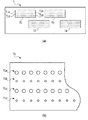
FIG. 1 is a block diagram showing a schematic configuration of an
記録ヘッドユニット7は、フルラインタイプの記録ヘッドユニットであり、記録媒体と対向する面に、記録媒体の搬送方向と直交する方向に配列した複数のノズルからなる、インク色ごとのノズル列を複数備えている。本実施形態の記録ヘッドは、熱によってインク中に発生する気泡によってノズルからインクを吐出する方式のものである。インクカートリッジ61〜64内の各インクは、インク導入管61a〜64aを通じて記録ヘッドの対応するインク色ごとの各ノズルに供給され、これらのノズルからインクが吐出されて、記録媒体100に記録が行われる。
The
記録媒体搬送機構8は、紙送りモーター81と紙送りローラー82を備えている。紙送りモーター81は紙送りローラー82を回転させることにより、記録媒体100を記録ヘッドユニット7の位置まで紙送りローラー82と直交する方向に搬送する。
The recording medium transport mechanism 8 includes a
コンピュータによって構成される制御ユニット2は、CPU3とRAM41とROM42などを有して構成されており、上述した記録ヘッドユニット7や紙送りローラー81の動作を制御する。また、CPU3は、ROM42内に記憶された制御プログラムをRAM41に展開して実行することにより、図4などを参照して後述する記録データ生成などの処理や記録媒体搬送機構8の制御などを行う。
The
図2(a)および(b)は、図1に示した記録ヘッドユニット7の詳細構成を1つのインク色について示す図である。図2(a)に示すように、本実施形態の記録ヘッドユニット7は、それぞれノズル配列方向と交差する方向に並ぶ4つのノズル列を備えた記録ヘッド(記録チップ)71〜74を千鳥状に配置して構成されるものである。すなわち、記録ヘッドユニットは、ノズルの一部同士を重複(オーバーラップ)させて、複数個が設けられている。これにより、一部重複する記録ヘッド(第1の記録ヘッドおよび第2の記録ヘッド)の記録領域が重複する。
2A and 2B are diagrams showing the detailed configuration of the
これらの千鳥状配置の記録ヘッドのノズルから吐出されるインクは、記録媒体の搬送とインク吐出のタイミングを調整することにより、記録ヘッドの配列方向に沿う1つのラスターを形成するようにドットを記録することができる。図2(b)は、記録ヘッドユニット7を構成する記録ヘッドの1つである記録ヘッド71の詳細を示す図である。記録ヘッド71は、2種類のドット径(第1のサイズと、第1のサイズより小さい第2のサイズ)を記録できるノズル列71a,71b,71c,71dから形成されている。このうち、ノズル列71aおよび71c(第1の記録素子列)は、ノズル列71bおよび71d(第2の記録素子列)より大きいドット径を記録することができる。すなわち、ノズル列71aおよび71cの各ノズルは、比較的大きい体積のインク滴を吐出し、ノズル列71bおよび71dの各ノズルは、比較的小さい体積のインク滴を吐出する。なお、本実施形態では、記録特性の異なるノズル列を71a・71cと71b・71dのように2列ずつ持つ構成としたが、それぞれ1列または3列以上としたり、千鳥配置など2次元的な配置としたりしてもよい。つまり、ノズル列が複数配列した記録ヘッドであればよい。また、本実施形態の記録ヘッドユニット7は熱により発生する気泡によってインクを吐出するものとしたが、この方式に限られるものではない。複数の記録ヘッドを搬送方向に直交する方向に配列し、さらに複数の記録特性を持つ記録ドットを同一のラスターに形成して画像データの記録を行うフルラインヘッドであればよい。例えば、ピエゾ式など他のインク吐出方式のインクジェット式記録ヘッドユニットであっても良いし、異なる記録特性を持つ記録ドットが記録可能であれば、1つのノズルから複数の異なる記録特性を持つ記録ドットを記録可能な記録ヘッドユニットでもよい。さらに、インク色についても、前述したCMYK以外のインクでもよい。
The ink ejected from the nozzles of these staggered recording heads records dots so as to form a single raster along the recording head arrangement direction by adjusting the timing of conveyance and ink ejection of the recording medium. can do. FIG. 2B is a diagram showing details of the
図3は、図1に示した制御ユニット2による、記録データ生成のための画像処理構成を示すブロック図である。また、図4は、画像処理の手順を示すフローチャートである。概略を説明すると、図3の画像入力部31によって、図4に示すステップS11の画像取得が行われる。同様に、色変換処理部32によってステップS12の色分解が行われ、量子化処理部33によってステップS13の量子化が行われる。さらに、ドット記録位置決定部34によってステップS14のドット位置決定が行われ、記録ドット配置分配処理部35によってステップS15の記録ドット分配が行われる。また、大小ノズル列ペア決定処理部36によってステップS16の大小ノズル列ペアの決定が行われる。そして、記録ドット分配処理部37は、大小ドット分配パターン記憶部41、記録特性取得部51、補正目標値設定部52、および大小ドット分配率決定部53を用いて、ステップS17のノズル吐出量補正を行う。さらに、つなぎマスク処理部38は、マスクパターン記憶部43を用いて、ステップS18、S19のつなぎ処理を行う。最後に、ステップS20で、以上の処理によって生成された記録データに基づき各ノズル列によるドットの記録、すなわち、図1にて上述した記録動作を行う。
FIG. 3 is a block diagram showing an image processing configuration for generating recording data by the
以下、図4に示した処理の詳細を以下に説明する。 Details of the processing shown in FIG. 4 will be described below.
<ドットデータ生成処理>
図4のステップS11〜S14で、ドットデータ生成処理が行われる。すなわち、例えば、メモリーカード91(図1)に保存された画像データは、図3に示す画像入力部31、色変換処理部32、量子化処理部33、ドット記録位置決定部34によって処理が施され、記録媒体上のドット配置で表される記録データに変換される。以下では、この記録ドット配置データ内の記録ドットの形成を表す記録データは記録ドットデータともいう。
<Dot data generation processing>
In steps S11 to S14 in FIG. 4, dot data generation processing is performed. That is, for example, the image data stored in the memory card 91 (FIG. 1) is processed by the
より詳細には、画像処理が開始されると、ステップS11で制御ユニット2は画像入力部31を用いてメモリーカード91より記録すべき画像データを読み込む。ここでは画像データは解像度600dpiでRGB各8bit256階調のカラー画像であるとして説明する。しかし、カラー画像によらずモノクロ画像でも同様に適用することができる。次に、ステップS12で、色変換処理部32は色変換処理を行い600dpiの解像度のCMYK各色8bit256階調の画像に変換する。この色変換処理は、R、G、Bの各階調値の組み合わせによって表現されているRGBカラー画像を、記録のために使用される各色の階調値によって表現されたデータに変換する処理である。記録装置1は、C、M、Y、Kの4色のインクを用いて画像を記録している。そこで、本実施形態の色変換処理部32は、RGBで表された画像データをC、M、Y、Kの各色の階調値によって表現されたデータに変換する処理を行う。
More specifically, when image processing is started, the
次に、ステップS13で、量子化処理部33は量子化処理を行う。この量子化処理は、8ビット256階調の階調数を持つ画像データを、記録装置1で記録可能な少ない階調(ここでは5値を例に説明する)に、階調値を低減させる処理である。一般的に、量子化処理としては誤差拡散法やディザ法が用いられることが多い。
Next, in step S13, the quantization processing unit 33 performs a quantization process. This quantization process reduces the gradation value of image data having the number of gradations of 8 bits and 256 gradations to a small number of gradations (here, 5 values will be described as an example) that can be recorded by the
図5(a)および(b)はこの量子化処理を説明する図である。図5(a)は、誤差拡散処理の概念を示し、図5(b)は、この誤差拡散おける、閾値、出力レベル、評価値の関係を示す図である。これら図に示すように、先ず、画像濃度値(In)と周辺画素からの拡散誤差値(dIn)とを加算して補正濃度値(In+dIn)を得る。そして、比較器にて、求めた補正濃度値(In+dIn)と閾値(threshold)とを比較し、補正濃度値の値に応じて閾値により定められた出力レベルを出力する。この場合において、補正濃度値(In+dIn)が“32以下”であれば、出力レベルとして“Level0”を、“32より大きく96以下”であれば、出力レベルとして“Level1”を出力する。次に、補正濃度値(In+dIn)から評価値(Evaluation)を引いた多値化誤差(Error=In+dIn-Evaluation)を算出し、誤差を周辺画素へ拡散させるために、重み付け演算を行って誤差バッファに加算する。ここで、出力Lレベルと評価値の関係は図5(b)に従い、出力レベルが”Level4“であるときは、評価値は”255“、”Level3“のときは”192“、”Level2“のときは”128“、”Level1“のときは”64“、”Level0“ときは”0“となる。最後に、注目画素位置に拡散された誤差値を誤差バッファから取り出し、重み係数の総和で正規化し、次の画素の拡散誤差(dIn)とする。以上の処理を全画素に繰り返し実行する。以上のようにして8ビット256階調のデータを5階調へと量子化する。
FIGS. 5A and 5B are diagrams for explaining this quantization process. FIG. 5A shows the concept of error diffusion processing, and FIG. 5B shows the relationship among threshold value, output level, and evaluation value in this error diffusion. As shown in these figures, first, an image density value (In) and a diffusion error value (dIn) from surrounding pixels are added to obtain a corrected density value (In + dIn). Then, the comparator compares the obtained corrected density value (In + dIn) with a threshold value (threshold), and outputs an output level determined by the threshold value according to the value of the corrected density value. In this case, if the correction density value (In + dIn) is “32 or less”, “
次に、ステップS14で、ドット記録位置決定部34は、記録画素単位で低階調に量子化された量子化後の画像データから、該記録画素内の記録ドット配置を決定する。図6は、記録画素が600dpiでLevel0〜4の5値の量子化後画像データを、記録ドット解像度1200dpiのドットパターンで表すためのドット記録位置を示したものである。例えば、量子化後の結果がLevel1の場合、600dpiの記録画素内には1ドットのみ記録され、そのドット記録位置は「左上(図6の(a))」「左下(図6の(b))」「右下(図6の(c))」「右上(図6の(d))」が繰り返される。他のレベルに対しても同様の操作を行い、画像データをドットのパターンデータに変換したデータのまとまりを記録ドット配置データとする。そして、この記録ドット配置データを、ステップS15で、記録媒体に対応した領域に配置されデータとするドット分配を行う。
Next, in step S14, the dot recording
図4に示すように、次にステップS16、S17で、ノズル吐出量補正処理、およびそれに続くステップS18、S19でつなぎ処理を行うが、これに関連して本発明が解決する問題点を、先ず、説明する。すなわち、つなぎ処理を適用することにより、ノズル吐出量補正処理における記録特性に応じた各ノズル列への記録データの分配において記録データの排他性が損なわれるという問題について説明する。 As shown in FIG. 4, the nozzle discharge amount correction process is performed in steps S16 and S17, and the connection process is performed in subsequent steps S18 and S19. ,explain. That is, the problem that the exclusivity of print data is lost in the distribution of print data to each nozzle row according to the print characteristics in the nozzle discharge amount correction process by applying the linkage process will be described.
図2(a)に示す、複数の記録ヘッドを配列したラインタイプの記録ヘッドユニットでは、隣り合う記録ヘッド間の重なり部分において、記録データをそれぞれの記録ヘッドでどのように分担して記録するのかを決める処理を行う(本明細書では、つなぎ処理という)。このつなぎ処理の1つの方法として、記録ヘッドのノズル列ごとにつなぎ処理を行う領域をずらす方法がある。図7は、隣接する記録ヘッド1,2の複数のノズル列A、B、C、Dの各列同士でのつなぎ処理をずらして行う方法を説明する図である。中央のマス目はノズル列を複数のノズルのブロックに分けた際の記録媒体上の位置に対応し、塗りつぶされたマスは記録に使用することを表している。図7示すように、記録ヘッド1、2の同じローマ字で示される列が使用される領域でそのノズル列のつなぎ処理が行われ、2ブロックずつずらしながらA〜D列のつなぎ処理が行われる。例えば、A列のつなぎ処理領域では、記録ヘッド1、2それぞれのノズル列A同士について、図8(c)、(d)で後述されるような記録データの振り分けが行われる。また、ノズル列B、C、Dについては、それぞれのノズル列に分配された記録データがそのままそのノズル列の記録データとされる。 In the line type recording head unit shown in FIG. 2A in which a plurality of recording heads are arranged, how the recording data is divided and recorded by the respective recording heads in the overlapping portion between adjacent recording heads. (In this specification, it is called a linkage process). As one method of this connection processing, there is a method of shifting the region for performing the connection processing for each nozzle row of the recording head. FIG. 7 is a diagram for explaining a method in which the connecting process between the plurality of nozzle arrays A, B, C, and D of the adjacent recording heads 1 and 2 is shifted. The central square corresponds to the position on the recording medium when the nozzle row is divided into a plurality of nozzle blocks, and the filled square represents that it is used for recording. As shown in FIG. 7, the nozzle row connection processing is performed in an area where the same roman letters of the recording heads 1 and 2 are used, and the A to D row connection processing is performed while shifting by two blocks. For example, in the connection processing area of row A, the print data is distributed as described later with reference to FIGS. 8C and 8D for the nozzle rows A of the print heads 1 and 2. For the nozzle rows B, C, and D, the print data distributed to the respective nozzle rows is directly used as print data for the nozzle rows.
ノズル吐出量補正を行った後、このつなぎ処理を行うと、ノズル吐出量補正において記録ヘッドごとに複数のノズル列に分配した記録データについて、記録ヘッド間相互の排他性が損なわれ、結果として、記録データの欠損や重複による濃度むらを生じることがある。すなわち、ノズル吐出量補正処理では、記録ヘッドごとにそれぞれの複数のノズル列に所定の分配率で記録データの分配が行われるが、分配された記録ヘッドごとの記録データは、複数のノズル間で排他性を持っている。そして、分配された記録データがそのまま個別に記録に用いられれば、そもそも排他性が損なわれることはない。しかし、その後に、各記録ヘッドの記録データのうちつなぎ処理に供される記録データについては、記録ヘッド間で関連づけられため、記録ヘッド間相互で排他性が損なわれる場合がある。 When this splicing process is performed after the nozzle discharge amount correction, the mutual exclusion between the print heads is lost for the print data distributed to the plurality of nozzle arrays for each print head in the nozzle discharge amount correction. Concentration unevenness may occur due to data loss or duplication. That is, in the nozzle discharge amount correction process, the print data is distributed to each of the plurality of nozzle rows for each print head at a predetermined distribution ratio. The print data for each distributed print head is distributed between the plurality of nozzles. Has exclusivity. If the distributed recording data is directly used for recording as it is, the exclusivity is not lost in the first place. However, since the recording data to be subjected to the splicing process among the recording data of each recording head is associated with each other between the recording heads, the mutual exclusivity may be lost between the recording heads.
図8(a)〜(d)は、記録データの欠損や重複による濃度むらの発生を説明する図である。説明を容易にするため記録ヘッド1、2が2列のノズル列を持つ場合を例にして説明する。図8(a)に示す1つのマス目は記録媒体上の画素に対応し、黒丸は記録データ(以下、記録ドットともいう)配置を表す。図8(a)に示すようにつなぎ領域ではすべての画素にドットが記録される記録ドット配置であるとする。図8(b)は、ノズル吐出量補正を行った記録ヘッド1、2の各ノズル列の記録ドット配置を示している。図8(b)は、一例として記録ヘッド1では各ノズル列への記録ドットの分配率が1:1、記録ヘッド2では1:3の場合を示している。図8(b)に示されるように、記録ヘッド1、2において記録ドットの分配率が異なるためつなぎ処理を行う記録ヘッド1のノズル列1−aと記録ヘッド2のノズル列2−aの記録ドット配置は一致していない。図8(c)は、つなぎ処理で記録ドットの分配を行うマスクを示している。図8(d)はノズル列1−aおよび2−aによりつなぎ処理が行われる領域で使用されるノズル列を示している。塗りつぶされたマスが使用されるノズル列を表しており、このつなぎ処理では、ノズル列1−a、2−a、2−bが使用される。
FIGS. 8A to 8D are diagrams for explaining the occurrence of density unevenness due to missing or overlapping recording data. For ease of explanation, the case where the recording heads 1 and 2 have two nozzle rows will be described as an example. One square shown in FIG. 8A corresponds to a pixel on the recording medium, and a black circle represents an arrangement of recording data (hereinafter also referred to as recording dots). As shown in FIG. 8A, it is assumed that the recording dot arrangement is such that dots are recorded in all pixels in the connection area. FIG. 8B shows a recording dot arrangement of each nozzle row of the recording heads 1 and 2 that has performed nozzle discharge amount correction. FIG. 8B shows, as an example, a case where the
図9(a)は、図8(c)に示すマスクAによって分配されたノズル列1−aの記録ドットおよびマスクBによって分配されたノズル列2−aの記録ドットの配置を示している。この結果、図8(d)に示されるつなぎ領域に使用されるすべてのノズル列の記録ドット配置(図8(b)の2−b、図9(a)の1−a、2−a)を合わせると、図9(b)で表される記録ドット配置となる。すなわち、図9(b)において、二重丸は2つのドットを記録することを表しており、空白はドットが記録されないことを表しており、記録ドットの欠損や重複が発生していることが分かる。この場合、図8(b)において、同じ記録ヘッドのノズル列1−aとノズル列1−bの記録データは、ノズル吐出量補正処理による分配によって相互に排他性を持っている。同じく、記録ヘッド2のノズル列2−aとノズル列2−bの記録データは、ノズル吐出量補正処理による分配によって相互に排他性を持っている。この状態に対して、つなぎ処理を行う領域では、上述のように、ノズル列1−a、ノズル列2−a、およびノズル列2−bの記録データが用いられる。この際、ノズル列1−aとノズル列2−aの記録データは、つなぎ処理のマスクA、Bによって相互に排他性がある。従って、ノズル列1−aとノズル列2−bの記録データの間で排他性がない状態となることがある。
FIG. 9A shows the arrangement of the recording dots of the nozzle array 1-a distributed by the mask A and the recording dots of the nozzle array 2-a distributed by the mask B shown in FIG. As a result, the recording dot arrangement of all the nozzle rows used in the connection area shown in FIG. 8D (2-b in FIG. 8B, 1-a, 2-a in FIG. 9A). Are combined, the recording dot arrangement shown in FIG. 9B is obtained. That is, in FIG. 9B, double circles indicate that two dots are recorded, blanks indicate that dots are not recorded, and recording dots are missing or overlapped. I understand. In this case, in FIG. 8B, the print data of the nozzle row 1-a and the nozzle row 1-b of the same print head are mutually exclusive due to the distribution by the nozzle discharge amount correction processing. Similarly, the print data of the nozzle row 2-a and the nozzle row 2-b of the
本発明は、以上のような、ノズル吐出量補正処理の後つなぎ処理を行うことによって生じ得る記録データの排他性の欠如による記録ドットの欠損や重複の発生を防止するものである。以下では、先ず、本実施形態に係るノズル吐出量補正およびつなぎ処理の概要について説明する。 The present invention prevents the occurrence of recording dot loss or duplication due to the lack of recording data exclusivity, which may occur by performing the linkage processing after the nozzle discharge amount correction processing as described above. In the following, first, an outline of nozzle discharge amount correction and connection processing according to the present embodiment will be described.
<ノズル吐出量補正>
ノズル吐出量補正は、図4におけるステップS16の大小ノズル列ペア決定処理の後、ステップS17で行われる。ステップS16の大小ノズル列ペア決定処理については、本発明のいくつかの実施形態として後述する。
<Nozzle discharge correction>
The nozzle discharge amount correction is performed in step S17 after the large / small nozzle row pair determination process in step S16 in FIG. The large / small nozzle row pair determination processing in step S16 will be described later as some embodiments of the present invention.
本実施形態のノズル吐出量補正における記録特性は、記録ヘッドユニット7の各記録ヘッド(71,72,73,74)のノズルの吐出量とする。
The recording characteristics in the nozzle discharge amount correction of the present embodiment are the discharge amounts of the nozzles of the recording heads (71, 72, 73, 74) of the
図10は、ノズル吐出量補正処理における、記録データを大小ノズルへ分配するための分配率を決定する処理を示すフローチャートである。ステップS01で、記録特性取得部51によって記録ヘッド71〜74それぞれにおける大ノズル列(記録ヘッド71の71aおよび71c)および小ノズル列(同71bおよび71d)の吐出量情報を得る。次に、ステップS02で、補正目標値設定部52によって、各記録ヘッド71〜74のノズルで吐出すべき目標吐出量を設定する。次に、ステップS03で、大小ドット分配率決定部53によって、記録ヘッドごとに読み取った吐出量と設定した補正目標吐出量とから、大、小ノズルに対する記録データの分配率を決定する。本実施形態では、ノズル列71aおよび71cの各ノズル平均吐出量が3ng、ノズル列71bおよび71dの各ノズル平均吐出量が2ng、目標吐出量が2.5ngであるから、記録ヘッド71の分配率は大ノズル列(3ng):小ノズル列(2ng)=1:1とする。
FIG. 10 is a flowchart showing a process of determining a distribution rate for distributing print data to large and small nozzles in the nozzle discharge amount correction process. In step S01, the recording
次に、以上のように決定された分配率で大、小ノズル列に分配する処理を説明する。図3に示す記録ドット分配処理部37は、大小ドット分配率決定部53に記録ドットを記録するノズル位置に関する情報(本実施形態ではどの記録ヘッドで記録されるかの情報)を伝達した後、記録ヘッドの記録特性情報に応じて決定された分配率情報を受け取る。続いて、その分配率情報を大小ドット分配パターン記憶部41に伝達した後、大小ドット分配パターンを受け取る。そして、その大小分配パターンを用いて、図4のステップS14で決定された記録ドット配置データ内の各記録ドットデータを、異なる記録特性を持つ記録ドットデータに分配して異なる記録特性のそれぞれの記録データを生成する。本実施形態では、3ngと2ngの2種類の記録ドットを用いて、それぞれの記録ドット数が1:1になるよう分配された大小それぞれの1200dpi、2値の大小記録ドット配置データを得る。
Next, a process of distributing the large and small nozzle rows with the distribution rate determined as described above will be described. The recording dot distribution processing unit 37 shown in FIG. 3 transmits information about the nozzle positions for recording the recording dots (information about which recording head is used for recording in this embodiment) to the large / small dot distribution
上記大小ドット分配パターン生成の一例としての処理を説明する。図11は、斥力ポテンシャルを用いた大小ドット分配パターン生成処理を示すフローチャートである。図11において、ステップS101で大小ドット分配パターンを生成したい量子化Levelの記録ドット配置を入力する。本説明では、量子化Level1として図12(a)の記録ドット配置を例に説明する。図12(a)の記録ドット配置は記録ドット配置データを記録媒体上のドットイメージとして表したものである。黒丸はドットの形成を表し、記録ドットデータのイメージに対応する。マス目は記録媒体上の画素を表す。次に、ステップS102で大小ドット分配率と、前記入力された量子化Levelの記録ドット数から必要な大ドット数を計算する。本実施形態では、図12(a)の記録ドット数が16で、大小ドット分配率が1:1のため、必要な大ドット数は16×0.5=8ドットとなる。次に、ステップS103で記録ドット配置のうち“斥力ポテンシャル_積算値”が最小の記録ドットを選択する。1ドット目の分配については、“斥力ポテンシャル_積算値”はいずれの位置も“0”であるため、任意の記録ドットを選択する。本説明では{X,Y}={7,4}(図12(b)の星印の位置)が選択されたものとする。次に、ステップS104で、選択した記録ドットを大ドットに分配する(図12(c−1)の二重丸印)。次に、ステップS105で“斥力ポテンシャル_積算値”に、分配された大ドットの斥力ポテンシャルを加算する。 A process as an example of generating the large and small dot distribution pattern will be described. FIG. 11 is a flowchart showing a large / small dot distribution pattern generation process using a repulsive potential. In FIG. 11, the recording dot arrangement of the quantization level for which a large and small dot distribution pattern is to be generated is input in step S101. In this description, the recording dot arrangement in FIG. 12A will be described as an example of quantization Level1. The recording dot arrangement in FIG. 12A represents the recording dot arrangement data as a dot image on the recording medium. Black circles indicate dot formation and correspond to the image of the recorded dot data. The squares represent pixels on the recording medium. Next, in step S102, the necessary number of large dots is calculated from the large and small dot distribution ratio and the number of recorded dots of the inputted quantization level. In the present embodiment, since the number of recording dots in FIG. 12A is 16 and the large / small dot distribution ratio is 1: 1, the required large number of dots is 16 × 0.5 = 8 dots. Next, in step S103, a recording dot having the smallest “repulsive potential_integrated value” is selected from the recording dot arrangement. Regarding the distribution of the first dot, since “repulsive potential_integrated value” is “0” at any position, an arbitrary recording dot is selected. In this description, it is assumed that {X, Y} = {7, 4} (the position of the star in FIG. 12B) is selected. Next, in step S104, the selected recording dots are distributed to large dots (double circles in FIG. 12C-1). Next, in step S105, the repulsive potential of the distributed large dots is added to “repulsive potential_integrated value”.
図13は、この斥力ポテンシャルを説明する図である。本実施形態では、配置ドットを中心により傾きの大きい斥力ポテンシャルを得るため、配置ドットの中心が“50000”、それ以外の点では、「10000÷距離の4乗」の等方的な斥力ポテンシャルを用いている。図13(a−1)はポテンシャルをグラフ化したもの、図13(a−2)は横軸X座標(0〜7)、縦軸Y座標(0〜7)の各座標の斥力ポテンシャルを表した表である。図13(a−1)、(a−2)から明らかなように、{4,4}を中心に急激な傾きをもったポテンシャルが得られている。この図13(a−1)、(a−2)に示すポテンシャルの中心を{0,0}に移したのが、図13(b−1)、(b−2)に示すものである。この単ドットの斥力ポテンシャルをPot_aloneとすると、位置{x,y}のポテンシャルは、
Pot_alone=50000 {x=0、y=0}
10000÷(x^2+y^2)^2 {x≠0、y≠0}
境界条件を満たすために、斜め方向も含む上下左右にも同じパターンが連続するとして、位置{x,y}における斥力ポテンシャルPot{x,y}は、
Pot_0(x,y)=Pot_alone(x+array_X、y+arrya_Y)
+Pot_alone(x 、y+arrya_Y)
+Pot_alone(x−array_X、y+arrya_Y)
+Pot_alone(x+array_X、y)
+Pot_alone(x 、y)
+Pot_alone(x−array_X、y)
+Pot_alone(x+array_X、y−array_Y)
+Pot_alone(x 、y−array_Y)
+Pot_alone(x−array_X、y−array_Y)
array_X:記録ドットパターンのXサイズ(本実施形態では8)
array_Y:記録ドットパターンのYサイズ(本実施形態では8)
となる。この時の斥力ポテンシャルの状態を図13(c−1)、(c−2)に示す。
FIG. 13 is a diagram for explaining this repulsive potential. In this embodiment, in order to obtain a repulsive potential having a large inclination with the arrangement dot as the center, the center of the arrangement dot is “50000”, and at other points, an isotropic repulsion potential of “10000 ÷ fourth of distance” is obtained. Used. FIG. 13 (a-1) is a graph of the potential. FIG. 13 (a-2) shows the repulsive potential at each coordinate of the horizontal axis X coordinate (0 to 7) and the vertical axis Y coordinate (0 to 7). It is a table. As is clear from FIGS. 13A-1 and 13A-2, a potential having a steep slope around {4, 4} is obtained. FIGS. 13B-1 and 13B-2 show the potential centers shown in FIGS. 13A-1 and 13A-2 moved to {0, 0}. If the repulsive potential of this single dot is Pot_alone, the potential at position {x, y} is
Pot_alone = 50000 {x = 0, y = 0}
10000 ÷ (x ^ 2 + y ^ 2) ^ 2 {x ≠ 0, y ≠ 0}
In order to satisfy the boundary condition, assuming that the same pattern continues in the vertical and horizontal directions including the diagonal direction, the repulsive potential Pot {x, y} at the position {x, y} is
Pot_0 (x, y) = Pot_alone (x + array_X, y + arrya_Y)
+ Pot_alone (x, y + arrya_Y)
+ Pot_alone (x−array_X, y + arrya_Y)
+ Pot_alone (x + array_X, y)
+ Pot_alone (x, y)
+ Pot_alone (x−array_X, y)
+ Pot_alone (x + array_X, y−array_Y)
+ Pot_alone (x, y−array_Y)
+ Pot_alone (x−array_X, y−array_Y)
array_X: X size of the recording dot pattern (8 in this embodiment)
array_Y: Y size of the recording dot pattern (8 in this embodiment)
It becomes. The state of the repulsive potential at this time is shown in FIGS. 13 (c-1) and (c-2).
任意の位置{a,b}に大ドットが配置された場合の{x,y}の斥力ポテンシャルは{a,b}からの相対位置を前記Pot_0(x,y)に代入すればよいので、斥力ポテンシャルは、
Pot_ab(x,y)=Pot_0( Pos_x, Pos_y)
Pos_x=x−a {x≧aの場合}、 a−x{x≦aの場合}
Pos_y=y−b {y≧bの場合}、 b−y{y≦bの場合}
となる。
Since the repulsive potential of {x, y} when a large dot is arranged at an arbitrary position {a, b}, the relative position from {a, b} may be substituted into the above Pot_0 (x, y). The repulsive potential is
Pot_ab (x, y) = Pot_0 (Pos_x, Pos_y)
Pos_x = x−a {if x ≧ a}, a−x {if x ≦ a}
Pos_y = y−b {if y ≧ b}, b−y {if y ≦ b}
It becomes.
図12(c−2)にステップS105で座標{7,4}に斥力ポテンシャルを加算した“斥力ポテンシャル_積算値”の積算値を示す。図12(c−3)は、このときの“斥力ポテンシャル_積算値”の等高線グラフである。図に示すように、大ドットを配置した{X,Y}={7,4}の位置を中心に斥力ポテンシャルの数値が積算されていることがわかる。 FIG. 12C-2 shows an integrated value of “repulsive potential_integrated value” obtained by adding the repulsive potential to the coordinates {7, 4} in step S105. FIG. 12C-3 is a contour graph of “repulsive potential_integrated value” at this time. As shown in the figure, it can be seen that the value of the repulsive potential is integrated around the position of {X, Y} = {7, 4} where the large dots are arranged.
次に、図11のステップS106で、大ドットを配置した位置の記録ドットを未配分から配分済みに変更する。次に、ステップS107で、配置済み大ドット数と先にステップS102で求めた必要大ドット数とを比較し、未達の場合にはステップS103に戻って繰り返す。 Next, in step S106 in FIG. 11, the recording dot at the position where the large dot is arranged is changed from unallocated to allocated. Next, in step S107, the number of arranged large dots is compared with the required number of large dots previously obtained in step S102, and if not reached, the process returns to step S103 and is repeated.
2ドット目の大ドット配置について引き続き説明する。図12(c−2)で“網掛け部分”が、記録ドットが配置されている箇所を示している。ステップS103でその“網掛け部分”から最も“斥力ポテンシャル_積算値”の小さい箇所を探し、該当箇所の記録ドットを選択する。図12(c−2)では、{2,1}および{2,7}が同じ値のため、乱数でどちらを選択するか決定し、本実施形態では{2,7}が選択されたものとする。記録ドットが選択されると、1ドット目と同様にステップS104、S105で選択ドットを大ドットに分配し、さらに“斥力ポテンシャル_積算値”に新しい大ドットの斥力ポテンシャルを加算する。図12(d−1)は{2,7}に大ドットを配分した様子、図12(d−2)は{2,7}に新たに配分された大ドットの斥力ポテンシャルを加算したときの“斥力ポテンシャル_積算値“を示す。また、図12(d−3)は”斥力ポテンシャル_積算値“の等高線グラフを示す。以上、配置済み大ドット数が必要大ドット数に達するまで上記処理は繰り返し実施される。図12(e)は大小分配率が1:1のとき、大ドットが全体の半分の8個配置された状態を示す説明図である。次に、必要大ドット数に達すると、図11のステップS108で残りの未配分の記録ドットは、小ドットに分配され、記録ドット配置および大小分配率に沿った大小分配パターンを得ることができる。図12(f)は本実施形態で斥力ポテンシャルを用いて大小分配パターンを生成した例である。このように斥力ポテンシャルを用いて大ドットを配置することにより、記録ドット配置の中で、大ドットがより分散されて配置される。大ドットが分散配置されると、大小分配率による濃度補正の位置によるばらつきが抑えられるとともに、より視認されやすい大ドットの粗密差がなくなるため、粒状性や一様性についても良好な結果が得られる。 Next, the arrangement of the second large dot will be described. In FIG. 12C-2, “shaded part” indicates a place where a recording dot is arranged. In step S103, a portion having the smallest “repulsive potential_integrated value” is searched from the “shaded portion”, and a recording dot at the corresponding portion is selected. In FIG. 12C-2, since {2, 1} and {2, 7} are the same value, it is determined which one to select with a random number, and {2, 7} is selected in this embodiment. And When a recording dot is selected, the selected dots are distributed to large dots in steps S104 and S105, and the repulsive potential of the new large dot is added to “repulsive potential_integrated value” in the same manner as the first dot. 12 (d-1) shows a state where large dots are allocated to {2, 7}, and FIG. 12 (d-2) shows a case where the repulsive potential of the large dots newly allocated to {2, 7} is added. “Repulsive potential_integrated value” is shown. FIG. 12D-3 shows a contour graph of “repulsive potential_integrated value”. As described above, the above process is repeated until the number of arranged large dots reaches the required number of large dots. FIG. 12E is an explanatory diagram showing a state in which eight large dots are arranged when the large / small distribution ratio is 1: 1. Next, when the required number of large dots is reached, the remaining undistributed recording dots are distributed to small dots in step S108 of FIG. 11, and a large / small distribution pattern according to the recording dot arrangement and the large / small distribution ratio can be obtained. . FIG. 12F shows an example in which a large and small distribution pattern is generated using a repulsive potential in this embodiment. By arranging the large dots using the repulsive potential in this way, the large dots are more dispersed in the recording dot arrangement. When large dots are distributed, variations due to density correction positions due to large and small distribution ratios are suppressed, and there is no difference in density between large dots that are more easily visible, resulting in good results for graininess and uniformity. It is done.
<つなぎ処理>
図14(a)〜(c)は、本発明の実施形態に係るつなぎ処理の概略を説明する図である。このつなぎ処理は、図3に示したつなぎ部マスク処理部37が主に実行する。図14(a)の中央部に示すように、つなぎ領域の記録データが記録媒体上の記録ドットの配置として表されるものとする。黒丸は、ドットの形成を表し、また、マス目は記録媒体上の画素を表す。図14(a)は、記録ヘッド71、72のつなぎ領域の記録データが、すべての画素にドットが形成されるデータである例を示している。本実施形態では、つなぎ処理に際して、つなぎ領域の各記録ヘッドに記録ドットデータを振り分けるために、マスクを利用する。図14(b)はその一例を示しており、ノズル列方向に記録ドットの濃度が変わる振り分けパターンである。つなぎ処理は、マスクと記録ドット配置データとの論理積を求める処理であり、図14(b)中の黒で示される四角と記録ドット配置データ内の記録ドットデータ(黒丸)との論理積を対応する画素ごとにとるものである。より具体的には、図14(b)に示すように、記録を許容するマスク画素について互いに排他関係にあるマスクAとマスクBが用いられる。マスクAを記録ヘッド71の記録データに、マスクBを記録ヘッド72の記録データに適用して、上記論理積演算を行うことにより、図14(c)に示すような、各記録ヘッドのつなぎ領域の記録データを得ることができる。図14(c)において、左側が記録ヘッド72に振り分けられた記録データを、右側が記録ヘッド71に振り分けられる記録データをそれぞれ示している。すなわち、所定領域内の複数の画素ごとに記録を許容するか否かを定めたマスクパターンを利用して分配を行う。
<Connection processing>
FIGS. 14A to 14C are diagrams for explaining the outline of the connection processing according to the embodiment of the present invention. This connecting process is mainly executed by the connecting part mask processing unit 37 shown in FIG. As shown in the central part of FIG. 14A, it is assumed that the recording data in the connection area is represented as an arrangement of recording dots on the recording medium. Black circles represent dot formation, and squares represent pixels on the recording medium. FIG. 14A shows an example in which the recording data in the connection area of the recording heads 71 and 72 is data in which dots are formed in all pixels. In the present embodiment, a mask is used to distribute the recording dot data to the recording heads in the connection area during the connection process. FIG. 14B shows an example thereof, which is a distribution pattern in which the density of recording dots changes in the nozzle row direction. The joining process is a process for obtaining a logical product of the mask and the recording dot arrangement data, and calculates a logical product of the square indicated by black in FIG. 14B and the recording dot data (black circle) in the recording dot arrangement data. This is taken for each corresponding pixel. More specifically, as shown in FIG. 14B, a mask A and a mask B that are mutually exclusive with respect to mask pixels that allow printing are used. By applying the above AND operation by applying the mask A to the recording data of the
以上、概略を説明したノズル吐出量補正処理およびつなぎ処理に関連して行われる大小ノズル列ペアの決定処理の実施形態について次に説明する。 Next, a description will be given of an embodiment of the large / small nozzle row pair determination process performed in association with the nozzle discharge amount correction process and the connection process as outlined above.
(第1実施形態)
<大小ノズル列ペア決定処理>
本処理は、図4に示すステップS15〜S16の処理に関連し、図3に示す大小ノズル列ペア決定処理部36によって実行されるものである。図15(a)〜(d)は、本発明の第1の実施形態に係る大小ノズル列ペアを決定する処理の詳細を説明する図である。
(First embodiment)
<Large and small nozzle row pair determination processing>
This processing is related to the processing in steps S15 to S16 shown in FIG. 4 and is executed by the large / small nozzle row pair
記録ドット配置分配処理部35(図3)は、ステップS11〜S14(図4)のドットデータ生成処理により生成された記録データを、図15(a)に示すような、相互に補完(排他)関係にある複数の記録データに分配する(ステップS15)。同図は、総ての画素にドットを記録する記録データを2つの記録データA、Bに分配する例を示している。続いて、ステップS16で、大小ノズル列ペア決定処理部36が、記録ヘッド71、72それぞれに対して記録データAの記録を行う大小ノズル列ペア、記録データBの記録を行う大小ノズル列ペアをそれぞれ決定する。本実施形態では、記録データAの記録を行う大小ノズル列ペアとして、ノズル列71a−71bペアおよびノズル列72a−72bペアを定め、記録データBの記録を行う大小ノズル列ペアとして、ノズル列71c−71dペアおよびノズル列72c−72dペアを定める。
The recording dot arrangement distribution processing unit 35 (FIG. 3) complements (excludes) the recording data generated by the dot data generation processing in steps S11 to S14 (FIG. 4) as shown in FIG. 15 (a). Distribute to a plurality of related recording data (step S15). This figure shows an example in which print data for printing dots on all pixels is distributed to two print data A and B. Subsequently, in step S16, the large / small nozzle array pair
次に、記録ドット分配処理部37は、ステップS17において、記録ヘッド71、72それぞれについて、大小ノズル列ペアの記録特性(吐出量の大小)に基づいて記録データA、Bそれぞれにノズル吐出量補正を行い、図15(b)に示す各ノズル列の記録データを生成する。図15(b)は、記録ヘッド71の大小分配率が1:1、記録ヘッド72の大小分配率が1:3の例を示している。
Next, in step S17, the recording dot distribution processing unit 37 corrects the nozzle ejection amount for each of the recording data A and B based on the recording characteristics (the magnitude of the ejection amount) of the large and small nozzle row pairs for each of the recording heads 71 and 72. To generate print data for each nozzle array shown in FIG. FIG. 15B shows an example in which the size distribution ratio of the
以上のように求められた、大小ノズルペア決定処理およびそれに基づくノズル吐出量補正処理の結果の記録データに対して、つなぎ部マスク処理部38は、大小ノズル列ペアに対するつなぎ処理を行う(図4のステップS18、S19)。本実施形態では、ノズル列71a−71bペアとノズル列72a−72bペア、ノズル列71c−71dペアとノズル列72c−72dペアによりつなぎ処理が行われる。図15(c)は、つなぎ処理で用いるマスクの一部を示す図である。大小のノズル列ペア71a−71bペアとノズル列72a−72bペアに対してつなぎ処理を行う場合、ノズル列71a−71bペアにマスクAを、ノズル列72a−72bペアにマスクBを用い、つなぎ領域の記録データ図15(d)が得られる。ノズル列71c−71dペアとノズル列72c−72dペアについても同様に、大小ノズルペア決定処理、ノズル吐出量補正処理およびつなぎ処理が行われる。すなわち、大小のノズル列ペア71c−71dペアとノズル列72c−72dペアに対してつなぎ処理を行う場合、ノズル列71c−71dペアにマスクAを、ノズル列72c−72dペアにマスクBを用いる。すなわち、オーバーラップする記録領域内の所定の部分内の複数の画素ごとに記録を許容するか否かを定めたマスクパターンを利用して分配の比率が決定される。
With respect to the print data obtained as a result of the large / small nozzle pair determination process and the nozzle discharge amount correction process based on the large / small nozzle pair determination process, the connection
以上のように生成されたつなぎ領域の記録データを用いて、ステップS20(図4)によって記録媒体上のつなぎ領域にドットが記録される。 Using the recording data of the connection area generated as described above, dots are recorded in the connection area on the recording medium in step S20 (FIG. 4).
以上の実施形態によれば、つなぎ処理を行う直前のノズル列71a−71bペアの各ノズル列の記録データ(図15(b))を合わせたドット配置は、図15(a)に示す記録データAと同じものである。また、ノズル列72a−72bペアの各ノズル列の記録データ(図15(b))を合わせたドット配置も、図15(a)に示す記録データAと同じものである。つまり、本発明において、記録ヘッドごとにつなぎ処理に用いられるノズル列の記録データを合わせた記録データで示される、つなぎ領域のドット配置は、つなぎ処理を行う直前において記録ヘッド間で同一になる。
According to the above embodiment, the dot arrangement obtained by combining the print data (FIG. 15B) of each nozzle row of the
換言すれば、つなぎ領域の記録に用いられる、ノズル列71a−71bペアとノズル列72a−72bペアの組の記録データと、ノズル列71c−71dペアとノズル列72c−72dペアの組の記録データとは、図15(a)に示す記録データAと記録データBにそれぞれ基づくものである。すなわち、これら記録データAと記録データBは互いに補完(排他)の関係にあることから、ノズル列71a−71bペアおよびノズル列72a−72bペアの組の記録データと、ノズル列71c−71dペアおよびノズル列72c−72dペアの組の記録データとは排他関係にあり、かつ記録ヘッド間で同じ排他関係にある。従って、マスク処理を経て最終的に得られるつなぎ領域の、記録ヘッド間の記録データも互いに(同じ)排他関係を有することになり、記録データの重複や欠損を生じることがない。
In other words, recording data of a set of
(第2実施形態)
図16、図17および図18は、本発明の第2の実施形態に係る、それぞれ画像処理の構成、手順および記録データの変化を説明する図であり、第1実施形態に係る図3、図4および図15と同様の図である。本実施形態は、ドットデータ生成処理、ノズル吐出量補正およびつなぎ処理は、第1実施形態と同様であるため、ここでは大小ノズル列ペアの決定処理の第1実施形態との違いを主に説明する。
(Second Embodiment)
16, FIG. 17, and FIG. 18 are diagrams for explaining the image processing configuration, procedure, and changes in recording data, respectively, according to the second embodiment of the present invention. FIG. 16 is a diagram similar to FIG. 15. In this embodiment, the dot data generation process, the nozzle discharge amount correction, and the connection process are the same as those in the first embodiment. Therefore, here, the differences from the first embodiment in the large / small nozzle row pair determination process are mainly described. To do.
<大小ノズル列ペア決定処理>
本実施形態の大小ノズル列ペア決定処理は、図17のステップS216〜S217において、図16に示す大小ノズル列ペア決定処理部237によって実行される。つなぎを行う記録ヘッドとして記録ヘッド71、72の場合を例に説明する。
<Large and small nozzle row pair determination processing>
The large / small nozzle row pair determination processing of the present embodiment is executed by the large / small nozzle row pair determination processing unit 237 shown in FIG. 16 in steps S216 to S217 of FIG. The case of the recording heads 71 and 72 as the recording heads to be connected will be described as an example.
図18(a)は、ステップS211〜S214のドット生成処理により生成された記録データ(図18(a)の記録ドット配置)を、記録ヘッド71、72の記録特性(吐出量の大小)に基づいてノズル吐出量補正(S215)を施した結果を示している。第1実施形態同様、記録ヘッド71の大小分配率が1:1、記録ヘッド72の大小分配比率が1:3の例を示している。
18A shows the print data generated by the dot generation processing in steps S211 to S214 (printed dot arrangement in FIG. 18A) based on the print characteristics of the print heads 71 and 72 (the magnitude of the discharge amount). The result of performing nozzle discharge amount correction (S215) is shown. As in the first embodiment, an example is shown in which the size distribution ratio of the
次に、図16の記録ドット配置分配処理部236は、記録ドット配置データを補完関係のある複数の記録ドット配置データに分配するために複数の分配マスクパターン(以下分配マスクと称する)を持つ。本実施形態では、図18(b)に示す2つの分配マスク(分配マスクA、B)を用いる。記録ドット配置分配処理部236は、記録ヘッド71、72ごとにノズル吐出量補正をした大小ドット記録データそれぞれを、分配マスクA、Bにより分配する。そして、大小ノズル列ペア決定処理部237は、分配された各記録データのドット記録を担当するノズル列を決める(図18(c))。分配マスクの働きはつなぎ部のマスクと同様である。 Next, the recording dot arrangement distribution processing unit 236 in FIG. 16 has a plurality of distribution mask patterns (hereinafter referred to as distribution masks) in order to distribute the recording dot arrangement data to a plurality of recording dot arrangement data having a complementary relationship. In this embodiment, two distribution masks (distribution masks A and B) shown in FIG. 18B are used. The recording dot arrangement / distribution processing unit 236 distributes the large and small dot recording data corrected for the nozzle discharge amount for each of the recording heads 71 and 72 by the distribution masks A and B, respectively. Then, the large / small nozzle row pair determination processing unit 237 determines a nozzle row in charge of dot recording of each distributed print data (FIG. 18C). The function of the distribution mask is the same as that of the joint mask.
図18(c)において、記録ヘッド71の大小ドット記録データ(図18(a)に示す71−大ドット、71−小ドット)それぞれに分配マスクAを適用して生成した記録データの担当ノズル列を、ノズル列71a、ノズル列71bに決定する。また、記録ヘッド71の大小ドット記録データ(図18(a)に示す71−大ドット、71−小ドット)それぞれに分配マスクBを適用して生成した記録データの担当ノズル列を、ノズル列71c、ノズル列71dに決定する。記録ヘッド72に対しても同様の方法で各記録ドット分配データの担当ノズル列を決定する。すなわち、記録ヘッド72の大小ドット記録データ(図18(a)に示す72−大ドット、72−小ドット)それぞれに分配マスクAを適用して生成した記録データの担当ノズル列を、ノズル列72a、ノズル列72bに決定する。また、記録ヘッド72の大小ドット記録データ(図18(a)に示す72−大ドット、72−小ドット)それぞれに分配マスクBを適用して生成した記録データの担当ノズル列を、ノズル列72c、ノズル列72dに決定する。
In FIG. 18C, the nozzle array in charge of the recording data generated by applying the distribution mask A to each of the large and small dot recording data of the recording head 71 (71-large dot, 71-small dot shown in FIG. 18A). Are determined as the
次に、大小ノズル列ペア決定処理部237は、同じ分配マスクを用いて分配された記録データを担当する大小ノズル列をペアとする(S217)。図18(c)において、ノズル列71aとノズル列71b、ノズル列71cとノズル列71d、ノズル列72aとノズル列72b、ノズル列72cとノズル列72dを、それぞれ大小ノズル列ペアとする。つなぎ処理は第1実施形態と同様にノズル列71a−71bペアとノズル列72a−72bペア、71c−71dペアとノズル列72c−72dペアによって行われる。
Next, the large / small nozzle row pair determination processing unit 237 sets a pair of large / small nozzle rows in charge of print data distributed using the same distribution mask (S217). In FIG. 18C, a
以上の処理の結果得られる、図18(c)に示す記録データ71a、71bを足し合わせた記録データのドット配置と、記録データ72a、72bを足し合わせた記録データのドット配置は一致している。すなわち、第2実施形態においても記録ヘッドごとにつなぎ処理に用いられるノズル列の記録ドット配置データを合わせた記録ドット配置データのつなぎ領域のドット形成位置は、つなぎ処理を行う直前において記録ヘッド間で同一になる。
The dot arrangement of the recording data obtained by adding the
換言すれば、つなぎ領域の記録に用いられる、ノズル列71a−71bペアとノズル列72a−72bペアの組の記録データと、ノズル列71c−71dペアとノズル列72c−72dペアの組の記録データとは、図18(a)に示すマスクA、Bの処理によって相互に同じ排他関係となる。従って、最終的に得られるつなぎ領域の、記録ヘッド間の記録データも互いに排他関係を有することになり、記録データの重複や欠損を生じることがない。
In other words, recording data of a set of
(他の実施形態)
図8に示した、記録ヘッドが2列のノズル列を有する場合も同様に本発明を適用することができる。例えば、図8(b)に示す記録ヘッド1の記録データ1−aに対して図18(a)に示すマスクAを適用し、記録ヘッド1の記録データ1−bに対して図18(a)に示すマスクBを適用する。同様に、記録ヘッド2の記録データ2−aに対してマスクAを適用し、記録データ2−bに対してマスクBを適用する。これにより、最終的に得られるつなぎ領域の、記録ヘッド間の記録データも互いに排他関係を有することになり、記録データの重複や欠損が生じることを防止できる。
(Other embodiments)
The present invention can be similarly applied to the case where the recording head shown in FIG. 8 has two nozzle rows. For example, the mask A shown in FIG. 18A is applied to the recording data 1-a of the
1 記録装置
7 記録ヘッド
34 ドット記録位置決定部
35 記録ドット配置分配処理部
36 大小ノズル列ペア決定処理部
37 記録ドット分配処理部
38 つなぎ部マスク処理部
53 0大小ドット分配率決定部
DESCRIPTION OF
Claims (10)
前記複数の記録ヘッドのうちの、同じ前記重複記録領域を分担して記録する第1の前記記録ヘッドと第2の前記記録ヘッドそれぞれについて、記録ヘッドに設けられた前記第1のノズル列の1つによるドット記録によって、前記重複記録領域に形成することを許容する画素を決定し、かつ、同じ記録ヘッドに設けられた前記第2のノズル列の1つによるドット記録によって前記重複記録領域に形成することを許容する他の画素を決定する第1決定手段と、
前記第1および第2の記録ヘッドそれぞれの前記第1および第2のノズル列のそれぞれの一部によって前記重複領域を記録するため、前記第1の記録ヘッドの前記第1および第2のノズル列の第1の組みによるドット記録によって形成することを許容する画素を、前記第1の記録ヘッドの前記第1および第2のノズル列に関して同じ第1の分配率で決定し、かつ、前記第2の記録ヘッドの前記第1および第2のノズル列の第2の組みによるドット記録によって形成することを許容する画素を、前記第2の記録ヘッドの前記第1および第2のノズル列に関して同じ第2の分配率で決定する第2決定手段と、
前記第1および第2決定手段による決定に基づき、記録ヘッドによって前記所定領域にドットを記録させる記録制御手段と、
を具えたことを特徴とするインクジェット記録装置。 A recording head unit having a plurality of recording heads, each of the plurality of recording heads being arranged in a column direction, and a first nozzle for forming dots of a first size by ink on a recording medium A first nozzle row formed by the second nozzle row formed by the second nozzles for forming dots of the second size by ink on the recording medium arranged in the row direction; The second size is different from the first size, and the color of the second size dot is the same as the color of the first size dot. The first and second nozzle rows are arranged in a direction intersecting the row direction, and the different recording heads are arranged so as to be displaced in the row direction, and the plurality of first and second nozzles of the different recording heads Each part is respectively recorded overlap recording region of the recording medium, a recording head unit,
For each of the first recording head and the second recording head that share the same overlapping recording area among the plurality of recording heads, one of the first nozzle rows provided in the recording head. the dot recording according to one, the overlap recording to determine the pixel to allow the formation in the region, and, formed on the overlapping recording area by one of the second nozzle row provided in the same recording head by the dot recording First determining means for determining other pixels to be allowed to do ;
For recording the overlap region by each part of the first and second recording heads each of said first and second nozzle rows, the first and second nozzle rows of the first recording head Pixels that are allowed to be formed by dot recording according to the first set of the first set and the second nozzle row of the first recording head are determined at the same first distribution ratio , and the second The pixels that are allowed to be formed by dot recording by the second set of the first and second nozzle rows of the recording head are the same as those of the first and second nozzle rows of the second recording head. A second determining means for determining at a distribution ratio of 2;
Recording control means for recording dots in the predetermined area by a recording head based on the determination by the first and second determining means;
An ink jet recording apparatus comprising:
前記複数の記録ヘッドのうちの、同じ前記重複記録領域を分担して記録する第1の前記記録ヘッドと第2の前記記録ヘッドそれぞれについて、記録ヘッドに設けられた前記第1のノズル列の1つによるドット記録によって、前記重複記録領域に形成することを許容する画素を決定し、かつ、同じ記録ヘッドに設けられた前記第2のノズル列の1つによるドット記録によって前記重複記録領域に形成することを許容する他の画素を決定する第1決定工程と、
前記第1および第2の記録ヘッドそれぞれの前記第1および第2のノズル列のそれぞれの一部によって前記重複領域を記録するため、前記第1の記録ヘッドの前記第1および第2のノズル列の第1の組みによるドット記録によって形成することを許容する画素を、前記第1の記録ヘッドの前記第1および第2のノズル列に関して同じ第1の分配率で決定し、かつ、前記第2の記録ヘッドの前記第1および第2のノズル列の第2の組みによるドット記録によって形成することを許容する画素を、前記第2の記録ヘッドの前記第1および第2のノズル列に関して同じ第2の分配率で決定する第2決定工程と、
前記第1および第2決定工程による決定に基づき、記録ヘッドによって前記所定領域にドットを記録させる記録制御工程と、
を有したことを特徴とする記録データ生成方法。 A recording head unit having a plurality of recording heads, each of the plurality of recording heads being arranged in a column direction, and a first nozzle for forming dots of a first size by ink on a recording medium A first nozzle row formed by the second nozzle row formed by the second nozzles for forming dots of the second size by ink on the recording medium arranged in the row direction; The second size is different from the first size, and the color of the second size dot is the same as the color of the first size dot. The first and second nozzle rows are arranged in a direction intersecting the row direction, and the different recording heads are arranged so as to be displaced in the row direction, and the plurality of first and second nozzle rows of the different printing heads are arranged. Each part is recorded respectively overlapping recording area of the recording medium, a recording head unit and a recording data generation method for generating a recording data used for recording by the use of,
For each of the first recording head and the second recording head that share the same overlapping recording area among the plurality of recording heads, one of the first nozzle rows provided in the recording head. the dot recording according to one, the overlap recording to determine the pixel to allow the formation in the region, and, formed on the overlapping recording area by one of the second nozzle row provided in the same recording head by the dot recording A first determining step of determining other pixels that are allowed to do ;
For recording the overlap region by each part of the first and second recording heads each of said first and second nozzle rows, the first and second nozzle rows of the first recording head Pixels that are allowed to be formed by dot recording according to the first set of the first set and the second nozzle row of the first recording head are determined at the same first distribution ratio , and the second The pixels that are allowed to be formed by dot recording by the second set of the first and second nozzle rows of the recording head are the same as those of the first and second nozzle rows of the second recording head. A second determination step of determining with a distribution ratio of 2;
A recording control step of recording dots in the predetermined area by a recording head based on the determination by the first and second determination steps;
A recording data generation method characterized by comprising:
Priority Applications (1)
| Application Number | Priority Date | Filing Date | Title |
|---|---|---|---|
| JP2012097899A JP6032932B2 (en) | 2011-04-27 | 2012-04-23 | Inkjet recording apparatus and recording data generation method |
Applications Claiming Priority (3)
| Application Number | Priority Date | Filing Date | Title |
|---|---|---|---|
| JP2011099989 | 2011-04-27 | ||
| JP2011099989 | 2011-04-27 | ||
| JP2012097899A JP6032932B2 (en) | 2011-04-27 | 2012-04-23 | Inkjet recording apparatus and recording data generation method |
Publications (3)
| Publication Number | Publication Date |
|---|---|
| JP2012236409A JP2012236409A (en) | 2012-12-06 |
| JP2012236409A5 JP2012236409A5 (en) | 2015-05-28 |
| JP6032932B2 true JP6032932B2 (en) | 2016-11-30 |
Family
ID=45954290
Family Applications (1)
| Application Number | Title | Priority Date | Filing Date |
|---|---|---|---|
| JP2012097899A Active JP6032932B2 (en) | 2011-04-27 | 2012-04-23 | Inkjet recording apparatus and recording data generation method |
Country Status (5)
| Country | Link |
|---|---|
| US (1) | US8705111B2 (en) |
| EP (1) | EP2518664B1 (en) |
| JP (1) | JP6032932B2 (en) |
| KR (1) | KR101513778B1 (en) |
| CN (1) | CN102756555B (en) |
Cited By (1)
| Publication number | Priority date | Publication date | Assignee | Title |
|---|---|---|---|---|
| US12045521B1 (en) | 2023-02-21 | 2024-07-23 | Ricoh Company, Ltd. | Halftone modification mechanism |
Families Citing this family (5)
| Publication number | Priority date | Publication date | Assignee | Title |
|---|---|---|---|---|
| JP6255976B2 (en) * | 2013-12-19 | 2018-01-10 | セイコーエプソン株式会社 | Print control apparatus and printer adjustment method |
| JP6397299B2 (en) * | 2014-10-07 | 2018-09-26 | キヤノン株式会社 | Recording apparatus and recording head drive control method |
| JP6957182B2 (en) * | 2017-03-31 | 2021-11-02 | キヤノン株式会社 | Recording device and recording method |
| JP7205223B2 (en) * | 2018-12-28 | 2023-01-17 | コニカミノルタ株式会社 | Image forming apparatus and image forming control method |
| CN115503345B (en) * | 2021-06-23 | 2023-08-15 | 深圳市汉森软件有限公司 | Method, device, equipment and storage medium for calibrating positions of two adjacent rows of nozzles |
Family Cites Families (14)
| Publication number | Priority date | Publication date | Assignee | Title |
|---|---|---|---|---|
| JP3029165B2 (en) * | 1992-12-04 | 2000-04-04 | キヤノン株式会社 | Ink jet recording device |
| JP3471482B2 (en) * | 1995-03-30 | 2003-12-02 | 株式会社東芝 | Plant data printing device |
| US6900907B2 (en) * | 2000-12-08 | 2005-05-31 | Xerox Corporation | Overlapping drop assignment for multi-level ink jet printing |
| JP4027135B2 (en) * | 2002-03-25 | 2007-12-26 | キヤノン株式会社 | Inkjet recording device |
| JP4366046B2 (en) * | 2002-06-20 | 2009-11-18 | キヤノン株式会社 | Image processing apparatus, image processing method, program, storage medium, and ink jet recording apparatus |
| JP2004142452A (en) * | 2002-10-03 | 2004-05-20 | Canon Inc | Method and apparatus for inkjet recording, and program |
| US7249815B2 (en) * | 2004-01-30 | 2007-07-31 | Hewlett-Packard Development Company, L.P. | Nozzle distribution |
| JP4307319B2 (en) * | 2004-04-30 | 2009-08-05 | キヤノン株式会社 | Recording apparatus and recording method |
| KR100612022B1 (en) | 2004-11-04 | 2006-08-11 | 삼성전자주식회사 | Method of printing ink-jet printer having wide printhead and the apparatus thereof |
| US7350902B2 (en) * | 2004-11-18 | 2008-04-01 | Eastman Kodak Company | Fluid ejection device nozzle array configuration |
| JP5213317B2 (en) * | 2006-08-22 | 2013-06-19 | キヤノン株式会社 | Inkjet recording apparatus and inkjet recording method |
| JP5147260B2 (en) * | 2007-02-23 | 2013-02-20 | キヤノン株式会社 | Data processing method, data processing apparatus, and data recording method |
| JP5121437B2 (en) * | 2007-12-20 | 2013-01-16 | キヤノン株式会社 | Inkjet recording device |
| JP5328247B2 (en) * | 2008-07-11 | 2013-10-30 | キヤノン株式会社 | Image forming apparatus, control method therefor, image processing apparatus, and program |
-
2012
- 2012-03-30 EP EP12002319.7A patent/EP2518664B1/en active Active
- 2012-04-09 US US13/442,197 patent/US8705111B2/en active Active
- 2012-04-19 KR KR1020120040896A patent/KR101513778B1/en active IP Right Grant
- 2012-04-23 JP JP2012097899A patent/JP6032932B2/en active Active
- 2012-04-27 CN CN201210129920.4A patent/CN102756555B/en active Active
Cited By (1)
| Publication number | Priority date | Publication date | Assignee | Title |
|---|---|---|---|---|
| US12045521B1 (en) | 2023-02-21 | 2024-07-23 | Ricoh Company, Ltd. | Halftone modification mechanism |
Also Published As
| Publication number | Publication date |
|---|---|
| EP2518664A2 (en) | 2012-10-31 |
| JP2012236409A (en) | 2012-12-06 |
| CN102756555B (en) | 2015-01-07 |
| CN102756555A (en) | 2012-10-31 |
| US20120274949A1 (en) | 2012-11-01 |
| KR101513778B1 (en) | 2015-04-20 |
| KR20120121842A (en) | 2012-11-06 |
| EP2518664A3 (en) | 2016-12-14 |
| US8705111B2 (en) | 2014-04-22 |
| EP2518664B1 (en) | 2018-09-12 |
Similar Documents
| Publication | Publication Date | Title |
|---|---|---|
| JP6032932B2 (en) | Inkjet recording apparatus and recording data generation method | |
| US8777343B2 (en) | Image processor, image processing method and inkjet printer involving a print head with parallel nozzle arrays | |
| JP5995642B2 (en) | Recording apparatus and recording method | |
| US8864266B2 (en) | Printing device and printing method | |
| JP6351342B2 (en) | Method for creating dot arrangement or threshold matrix, image processing apparatus, and storage medium | |
| JP5473420B2 (en) | DATA GENERATION DEVICE, INKJET RECORDING DEVICE, PROGRAM, AND DATA GENERATION METHOD | |
| JP4419947B2 (en) | Printing apparatus, printing apparatus control program, printing apparatus control method, printing data generation apparatus, printing data generation program, and printing data generation method | |
| JP4428362B2 (en) | Printing apparatus, printing program, printing method and printing control apparatus, printing control program, printing control method, and recording medium recording the program | |
| US20100245871A1 (en) | Method of correcting pixel data and fluid ejecting apparatus | |
| JP4385626B2 (en) | Image processing apparatus, image processing method, and image processing program | |
| JP2012232444A (en) | Inkjet recording apparatus and inkjet recording method | |
| US7497538B2 (en) | Method of multipass printing using a plurality of halftone patterns of dots | |
| US8998367B2 (en) | Image processing apparatus and image processing method | |
| US8052242B2 (en) | Image forming apparatus and image forming method | |
| JP5268875B2 (en) | Image forming apparatus and image forming method | |
| US20060109308A1 (en) | Image processing device and image processing method | |
| JP4983982B2 (en) | Image recording method and image recording apparatus | |
| US7433083B2 (en) | Halftone-image processing device | |
| JP6372410B2 (en) | Data correction method, correction function acquisition method, and inkjet printer. | |
| US20100245441A1 (en) | Fluid ejecting apparatus and method of correcting pixel data | |
| JP2006212907A (en) | Printing apparatus, printing program, printing method and image processing apparatus, image processing program, image processing method, and recording medium recorded with the same | |
| JP2007008176A (en) | Printer, printer control program, printer control method, apparatus for generating printing data, program for generating printing data, and method for generating printing data | |
| US11648782B2 (en) | Image processing apparatus, image processing method, and storage medium | |
| JP2007015397A (en) | Printing device, printing device control program, printing device control method, printing data generating device, printing data generating program, and printing data generating method | |
| JP2015074086A (en) | Ink jet recorder and record density unevenness correction method for the same |
Legal Events
| Date | Code | Title | Description |
|---|---|---|---|
| A521 | Request for written amendment filed |
Free format text: JAPANESE INTERMEDIATE CODE: A523 Effective date: 20150409 |
|
| A621 | Written request for application examination |
Free format text: JAPANESE INTERMEDIATE CODE: A621 Effective date: 20150409 |
|
| A977 | Report on retrieval |
Free format text: JAPANESE INTERMEDIATE CODE: A971007 Effective date: 20160224 |
|
| A131 | Notification of reasons for refusal |
Free format text: JAPANESE INTERMEDIATE CODE: A131 Effective date: 20160308 |
|
| A521 | Request for written amendment filed |
Free format text: JAPANESE INTERMEDIATE CODE: A523 Effective date: 20160428 |
|
| TRDD | Decision of grant or rejection written | ||
| A01 | Written decision to grant a patent or to grant a registration (utility model) |
Free format text: JAPANESE INTERMEDIATE CODE: A01 Effective date: 20160927 |
|
| A61 | First payment of annual fees (during grant procedure) |
Free format text: JAPANESE INTERMEDIATE CODE: A61 Effective date: 20161025 |
|
| R151 | Written notification of patent or utility model registration |
Ref document number: 6032932 Country of ref document: JP Free format text: JAPANESE INTERMEDIATE CODE: R151 |