JP5328247B2 - Image forming apparatus, control method therefor, image processing apparatus, and program - Google Patents
Image forming apparatus, control method therefor, image processing apparatus, and program Download PDFInfo
- Publication number
- JP5328247B2 JP5328247B2 JP2008182035A JP2008182035A JP5328247B2 JP 5328247 B2 JP5328247 B2 JP 5328247B2 JP 2008182035 A JP2008182035 A JP 2008182035A JP 2008182035 A JP2008182035 A JP 2008182035A JP 5328247 B2 JP5328247 B2 JP 5328247B2
- Authority
- JP
- Japan
- Prior art keywords
- recording
- discharge port
- ejection
- image
- binary
- Prior art date
- Legal status (The legal status is an assumption and is not a legal conclusion. Google has not performed a legal analysis and makes no representation as to the accuracy of the status listed.)
- Expired - Fee Related
Links
Images


Abstract
Description
本発明は、記録媒体上の同一領域に対して、同色の画像を形成する略平行に配列された第1の吐出口列と第2の吐出口列を有する記録ヘッドを備えた画像形成装置、その制御方法、プログラム及び画像処理装置に関する。 The present invention is, for the same area on the recording medium, an image forming apparatus including a first ejection outlet array and the recording head having a second ejection outlet arrays which are arranged substantially parallel to the formation of the same color image, The present invention relates to a control method , a program, and an image processing apparatus .
プリンタや複写機等、或いはコンピュータやワードプロセッサ等を含む複合電子機器やワークステーション等の出力機器として用いられる記録装置は、記録情報に基づいて用紙等の記録媒体に画像(文字や記号等を含む)を記録するように構成されている。このような記録装置は、記録方式によって、インクジェット式、ワイヤドット式、サーマル式、レーザービーム式等に分類される。 A recording device used as an output device such as a printer, a copying machine, or a composite electronic device including a computer or a word processor, or a workstation, has an image (including characters and symbols) on a recording medium such as paper based on the recorded information. Is configured to record. Such a recording apparatus is classified into an ink jet type, a wire dot type, a thermal type, a laser beam type, and the like according to a recording method.
各方式の記録装置のうち、インクジェット式の記録装置(インクジェット記録装置)は、記録手段としてインクジェット記録ヘッド(以下、記録ヘッド)を用い、その記録ヘッドの吐出口から記録媒体に向かってインクを吐出して記録を行うものである。このようなインクジェット記録装置は、記録ヘッドのコンパクト化が容易であること、高精細の画像を高速に形成できること、いわゆる普通紙に特別の処理を必要とせずに記録することができランニングコストが低廉であるという利点を有している。また、ノンインパクト方式であるので騒音が小さいこと、多色のインクを使用してカラー画像を形成するための構成を採るのが容易であること、サイズの大きな記録媒体への記録に対応した構成とし易い等の利点も有している。 Among the recording apparatuses of each type, an ink jet recording apparatus (ink jet recording apparatus) uses an ink jet recording head (hereinafter referred to as a recording head) as a recording unit, and ejects ink from a discharge port of the recording head toward a recording medium. And recording. Such an ink jet recording apparatus is easy to downsize the recording head, can form high-definition images at high speed, can record on so-called plain paper without requiring special processing, and has low running cost. It has the advantage of being. In addition, since it is a non-impact method, noise is low, it is easy to adopt a configuration for forming a color image using multi-color ink, and a configuration corresponding to recording on a large recording medium It has the advantage that it is easy to.
記録媒体の搬送方向(副走査方向)と交差する主走査方向に走査しながら記録を行ういわゆるシリアルタイプのインクジェット記録装置においては、記録媒体に沿って移動する記録ヘッドを用いて画像を記録する。すなわち、記録ヘッドによって1主走査分の記録動作を終了する毎に記録媒体を所定量ずつ搬送する動作を繰り返すことにより、記録媒体全域に対する記録を行う。 In a so-called serial type inkjet recording apparatus that performs recording while scanning in the main scanning direction that intersects the conveyance direction (sub-scanning direction) of the recording medium, an image is recorded using a recording head that moves along the recording medium. That is, every time the recording operation for one main scan is completed by the recording head, the recording medium is conveyed by a predetermined amount, thereby performing recording on the entire recording medium.
一方、記録ヘッドが記録媒体の幅に相当する記録幅をもち、記録媒体の搬送方向の移動のみを伴ういわゆるフルラインタイプのインクジェット記録装置においては、記録媒体を所定位置にセットし、記録媒体を搬送しながら1ライン分の記録動作を連続して行うことにより、記録媒体全域に対する記録を行う。このようなフルラインタイプのインクジェット記録装置は、画像形成の一層の高速化が可能であり、最近ニーズが高まっているオンデマンド記録用の記録装置としての可能性が注目されている(例えば特許文献1参照)。 On the other hand, in a so-called full-line type ink jet recording apparatus in which the recording head has a recording width corresponding to the width of the recording medium and involves only movement in the conveying direction of the recording medium, the recording medium is set at a predetermined position, and the recording medium is Recording is performed on the entire recording medium by continuously performing a recording operation for one line while being conveyed. Such a full-line type ink jet recording apparatus is capable of further increasing the speed of image formation, and has recently attracted attention as a recording apparatus for on-demand recording, for which demand is increasing (for example, Patent Documents). 1).
このようなオンデマンド記録用のフルラインタイプの記録装置において、文章等モノカラーの記録には、例えば解像度600×600dpi(ドット/インチ)以上の解像度でA3サイズの記録媒体に毎分30頁以上で記録することが求められる。また、写真のようなフルカラー画像の記録には、例えば1200×1200dpi以上の高い解像度でA3サイズの記録媒体に毎分30頁以上で記録することが求められる。 In such a full-line type recording apparatus for on-demand recording, for mono-color recording such as text, for example, 30 pages or more per minute on an A3 size recording medium with a resolution of 600 × 600 dpi (dots / inch) or more. Recording is required. For recording a full-color image such as a photograph, it is required to record at a high resolution of, for example, 1200 × 1200 dpi on an A3 size recording medium at 30 pages or more per minute.
ところで、フルラインタイプの記録装置に用いられる記録ヘッドにおいて、記録媒体の記録領域の全幅に渡って位置するインクジェット記録素子、特にインクジェット記録素子の一部を成す吐出口を全て欠陥なく加工することは現状難しい。例えば、フルラインタイプの記録装置において、A3サイズの用紙に1200dpiの解像度の記録を行うためには、記録ヘッドに約1万4千個の吐出口(記録幅約280mm)を形成することが必要となる。このような多数の吐出口の全てを一つの欠陥もなく加工することは、その製造プロセス上困難を伴う。また、このような記録ヘッドを製造できたとしても、良品率が低く製造コストが多大となってしまう。 By the way, in a recording head used in a full-line type recording apparatus, it is possible to process all of the ink jet recording elements positioned over the entire width of the recording area of the recording medium, in particular, all the ejection openings forming part of the ink jet recording elements without any defects. Currently difficult. For example, in a full-line type recording apparatus, in order to perform recording at a resolution of 1200 dpi on A3 size paper, it is necessary to form about 14,000 discharge ports (recording width about 280 mm) in the recording head. It becomes. Processing all of such a large number of discharge ports without one defect is difficult in terms of the manufacturing process. Even if such a recording head can be manufactured, the yield rate is low and the manufacturing cost is high.
上述したような理由から、フルラインタイプの記録ヘッドとして、いわゆる長尺つなぎヘッドが提案されている。つなぎヘッドは、複数の記録素子が配列された吐出口列を略平行に複数列配した記録チップを、前記吐出口列方向につなげてなる記録ヘッドである。つまり、シリアルタイプにおいて用いられているような比較的安価な短尺チップ形態の記録ヘッドを吐出口列方向に複数個つなぎ合わせるように、それらのチップを高精度に配列することによって長尺化を実現する記録ヘッドである。 For the reasons described above, a so-called long connecting head has been proposed as a full-line type recording head. The connecting head is a recording head formed by connecting, in the direction of the discharge port array, a plurality of recording chips in which a plurality of discharge port arrays in which a plurality of recording elements are arranged are arranged substantially in parallel. In other words, a longer length is realized by arranging these chips with high accuracy so that a plurality of relatively inexpensive short-chip-type recording heads used in the serial type are connected in the direction of the discharge port array. Recording head.
なお、ここでは、フルラインタイプの記録ヘッドとしてのつなぎヘッド構成に関して述べたが、いわゆるシリアルタイプの記録ヘッドにおいても、つなぎヘッド構成により長尺化を実現することができる。 Although the connection head configuration as a full-line type recording head has been described here, a so-called serial type recording head can also be made longer by the connection head configuration.
しかしながら、つなぎヘッドは、その構成上、いわゆるつなぎスジが発生しやすいという課題がある。つなぎスジとは、記録チップ間で吐出口列の端部が互いに隣り合う部分における画質劣化のことである。その原因としては、記録装置の記録媒体の搬送バラツキ(いわゆる搬送蛇行)や、フルラインタイプの記録ヘッドと記録媒体との相対位置関係に発生する傾きがある。これらの影響のため、つなぎ部分において隣り合う記録素子の吐出口によって形成される吐出口ピッチが、他の吐出口ピッチと同一とならず、記録された画像上に、記録チップのつなぎ部分に対応したスジ(つなぎスジ)が発生することがあった。 However, the connection head has a problem that a so-called connection streak is likely to occur due to its configuration. The connecting stripe is a deterioration in image quality at a portion where the end portions of the ejection port array are adjacent to each other between the recording chips. This is caused by variations in the conveyance of the recording medium of the recording apparatus (so-called conveyance meandering) and an inclination that occurs in the relative positional relationship between the full-line type recording head and the recording medium. Because of these effects, the discharge port pitch formed by the discharge ports of the adjacent recording elements in the connection portion is not the same as the other discharge port pitch, and corresponds to the connection portion of the recording chip on the recorded image. May occur.
つなぎヘッドの構成上、つなぎ部分で記録に使用される吐出口列の吐出口列方向に対する列間距離が、非つなぎ部分で記録に使用される吐出口列よりも大きくなってしまう場合が多い。このため、つなぎ部分において、上記搬送蛇行や傾き等の影響を受けやすいことが一因として考えられる。 Due to the structure of the connection head, the distance between the discharge port arrays used for recording at the connection portion in the discharge port array direction is often larger than the discharge port array used for recording at the non-connection portion. For this reason, it is considered that one of the reasons is that the connecting portion is easily influenced by the above-described meandering and tilting.
また、上述の列間距離が大きくなるほどそれに応じてつなぎスジがより顕著に発生し易いことを確認している。図7は、つなぎ部分における列間距離の大小とつなぎスジの発生の程度を表わす説明図である。図7(a)、(b)において、つなぎ部分の列間距離が小さい場合と大きな場合についてそれぞれ示している。図7(a)は傾きなし(記録ヘッドと記録媒体間の関係)の場合であり、傾きがなければ、つなぎスジの原因となる着弾位置ズレは列間距離の影響では生じない。一方、図7(b)は傾きあり(記録ヘッドと記録媒体間の関係)の場合であり、つなぎ部分の列間距離が大きい方が、同じ程度の傾きによってつなぎ部分のズレが大きくなってしまうことがわかる。すなわち、つなぎ部分の列間距離に比例して、つなぎ部分のズレが増大してしまう。図7(b)では、つなぎ部分の記録濃度が低くなる場合のスジとなる場合の傾きの例を示したが、反対側の傾きが生じた場合につなぎ部分の記録濃度が高くなる場合のスジとなる場合においても、列間距離に比例して、つなぎ部分のズレが増大してしまうことは言うまでもない。 In addition, it has been confirmed that as the above-described inter-column distance is increased, the connecting streaks are more prominently generated accordingly. FIG. 7 is an explanatory diagram showing the magnitude of the inter-column distance in the connecting portion and the degree of occurrence of connecting stripes. FIGS. 7A and 7B respectively show a case where the distance between the columns of the connecting portion is small and a case where the distance is large. FIG. 7A shows a case where there is no inclination (relationship between the recording head and the recording medium). If there is no inclination, the landing position deviation that causes the connecting stripe does not occur due to the effect of the inter-column distance. On the other hand, FIG. 7B shows a case where there is an inclination (relationship between the recording head and the recording medium). As the inter-column distance of the connecting portion is larger, the displacement of the connecting portion becomes larger due to the same degree of inclination. I understand that. That is, the shift of the connecting portion increases in proportion to the distance between the rows of the connecting portion. FIG. 7B shows an example of the slope when the recording density of the joint portion is low, but the stripe when the recording density of the joint portion is high when the opposite slope occurs is shown. Even in such a case, it goes without saying that the shift of the connecting portion increases in proportion to the inter-column distance.
この課題を解決するためには、上述の列間距離をできるだけ小さくすれば、その分、つなぎスジの発生を抑制することができると考えられる。しかしながら、吐出口の配置や吐出口を備える記録素子の配線レイアウト、及び、記録ヘッドとそれを保護するキャップとが接触するスペース部の確保等の兼ね合いから、つなぎ部分での列間距離を近づけるのは難しい。 In order to solve this problem, it is considered that if the above-described inter-column distance is made as small as possible, the generation of connecting stripes can be suppressed accordingly. However, the distance between the columns at the connecting portion is reduced from the viewpoint of the arrangement of the ejection openings, the wiring layout of the recording element including the ejection openings, and the securing of the space portion where the recording head and the cap protecting the recording head come into contact. Is difficult.
このようなつなぎヘッドによって生じるつなぎスジに対しては、特許文献1でも開示されているとおり、これまで改善策がいくつか提案されている。例えば、つなぎ部分のチップ配列を高精度に行うための配列方法や配列装置を用いて、吐出口ピッチのズレを小さくする方法がある。
As disclosed in
また、他の対策としては、チップのつなぎ部分において、それぞれのチップ端の吐出口を吐出列方向に隣接させるように配列させず、それぞれのチップ端における所定数ずつの吐出口を記録媒体の搬送方向に並べてオーバーラップさせて配列する方法がある。この場合、記録時には、互いにオーバーラップする両方の吐出口からインクを吐出させることによって、つなぎスジを目立たなくする。具体的には、互いにオーバーラップする両方の吐出口にオーバーラップ部分で記録すべき吐出データのパターンが互いに排他となるように割り振る。このような割り振りは、データ割り振りマスク等の処理を施すことで実現できる。 Further, as another countermeasure, in the connecting portion of the chips, the discharge ports at the respective chip ends are not arranged so as to be adjacent to each other in the discharge row direction, and a predetermined number of the discharge ports at the respective chip ends are conveyed. There is a method of arranging in an overlapping manner in the direction. In this case, at the time of recording, ink is ejected from both ejection ports that overlap each other, thereby making the connecting stripe inconspicuous. Specifically, the ejection data patterns to be recorded in the overlapping portion are allocated to both ejection ports that overlap each other so that they are mutually exclusive. Such allocation can be realized by performing processing such as data allocation masking.
また、つなぎ部を構成する各吐出口列が記録を行うドットの数を適宜増減させて補正を行うことで、つなぎスジを目立たなくする方法もある。 There is also a method of making the connecting stripes inconspicuous by making corrections by appropriately increasing or decreasing the number of dots to be recorded by each ejection port array constituting the connecting portion.
しかしながら、これらの対策は、いずれも写真調の記録を行う際に発生するつなぎスジに対しては、決して十分とはいえないものであった。 However, none of these measures can be said to be sufficient with respect to the connecting stripes generated when recording a photographic tone.
本願発明者が鋭意検討した結果、つなぎ部において、互いにオーバーラップする吐出口列のそれぞれで記録を担う記録パターン同士のドット配置の関係を工夫することで、つなぎ部でのズレが発生した場合に、つなぎスジを目立ちにくくすることが可能であることが明らかとなった。つなぎ部を構成する記録パターン同士は排他関係とするのが一般的だが、その関係を崩し、敢えていくつかのドットは同位置に記録するようにし記録パターン間同士の記録位置のズレが生じたとしても、つなぎ部の画質の変動を少なくできることがわかった。加えて、つなぎ部の列間距離に応じて、変動に対する強さを変化させるべく記録パターン同士のドット配置の関係を変化させれば、つなぎ部の列間距離が離れた場合でもつなぎスジの発生の程度を緩和し得ることがわかった。 As a result of intensive studies by the inventor of the present application, by devising the relationship between the dot arrangements of the recording patterns responsible for recording in each of the overlapping discharge port arrays in the connecting portion, when a shift occurs in the connecting portion It has become clear that the connecting stripes can be made inconspicuous. It is common for the recording patterns that make up the joints to be in an exclusive relationship, but this relationship was broken, and some dots were recorded at the same position, and there was a shift in the recording position between the recording patterns. However, it was found that fluctuations in image quality at the joint could be reduced. In addition, if the dot arrangement relationship between the recording patterns is changed to change the strength against fluctuations according to the distance between the rows of the joint portion, the connecting stripe is generated even if the distance between the rows of the joint portion is separated. It was found that the degree of can be relaxed.
本発明は、上述のような課題を鑑みてなされたものであり、つなぎ構成によって長尺化した記録ヘッドを用いて記録の高速化を維持しつつ、つなぎスジの発生を抑制して記録画像の高画質化を達成できるようにすることを目的とする。 The present invention has been made in view of the above-described problems, and while maintaining a high-speed recording using a recording head that is elongated by a connection configuration, the occurrence of connection stripes is suppressed and the recorded image is recorded. The purpose is to achieve high image quality.
本発明の画像形成装置は、記録媒体上の同一領域に対して、同色の画像を形成する略平行に配列された第1の吐出口列と第2の吐出口列を有する記録ヘッドを、前記吐出口列方向と略直行する方向に記録媒体上を相対的に移動させることにより画像を形成させる画像形成装置であって、画像データに基づいて、前記吐出口列それぞれに対応する2値の吐出データを生成する生成手段を有し、前記生成手段は、前記第1の吐出口列と前記第2の吐出口列との列間距離が小さいほど、前記第1の吐出口列に対応する2値の吐出データと前記第2の吐出口列に対応する2値の吐出データとの排他関係が強くなるように、前記吐出口列それぞれに対応する2値の吐出データを生成することを特徴とする。
本発明の画像形成装置の制御方法は、記録媒体上の同一領域に対して、同色の画像を形成する略平行に配列された第1の吐出口列と第2の吐出口列を有する記録ヘッドを、前記吐出口列方向と略直行する方向に記録媒体上を相対的に移動させることにより画像を形成させる画像形成装置の制御方法であって、画像データに基づいて、前記吐出口列それぞれに対応する2値の吐出データを生成する生成ステップを有し、前記生成ステップは、前記第1の吐出口列と前記第2の吐出口列との列間距離が小さいほど、前記第1の吐出口列に対応する2値の吐出データと前記第2の吐出口列に対応する2値の吐出データとの排他関係が強くなるように、前記吐出口列それぞれに対応する2値の吐出データを生成することを特徴とする。
本発明のプログラムは、記録媒体上の同一領域に対して、同色の画像を形成する略平行に配列された第1の吐出口列と第2の吐出口列を有する記録ヘッドを、前記吐出口列方向と略直行する方向に記録媒体上を相対的に移動させることにより画像を形成させる画像形成装置を制御するためのプログラムであって、画像データに基づいて、前記吐出口列それぞれに対応する2値の吐出データを生成する生成処理をコンピュータに実行させ、前記生成処理は、前記第1の吐出口列と前記第2の吐出口列との列間距離が小さいほど、前記第1の吐出口列に対応する2値の吐出データと前記第2の吐出口列に対応する2値の吐出データとの排他関係が強くなるように、前記吐出口列それぞれに対応する2値の吐出データを生成することを特徴とする。
本発明の画像処理装置は、記録媒体上の同一領域に対して、同色の画像を形成する略平行に配列された第1の吐出口列と第2の吐出口列を有する記録ヘッドを、前記吐出口列方向と略直行する方向に記録媒体上を相対的に移動させることにより画像を形成させる画像形成装置のための画像処理装置であって、画像データに基づいて、前記吐出口列それぞれに対応する2値の吐出データを生成する生成手段を有し、前記生成手段は、前記第1の吐出口列と前記第2の吐出口列との列間距離が小さいほど、前記第1の吐出口列に対応する2値の吐出データと前記第2の吐出口列に対応する2値の吐出データとの排他関係が強くなるように、前記吐出口列それぞれに対応する2値の吐出データを生成することを特徴とする。
The image forming apparatus of the present invention, for the same area on the recording medium, a first outlet row and the recording head having a second ejection outlet arrays which are arranged substantially parallel to the formation of the same color image, the An image forming apparatus for forming an image by relatively moving on a recording medium in a direction substantially perpendicular to a discharge port array direction, and binary discharge corresponding to each of the discharge port arrays based on image data The generating unit generates data, and the generating unit corresponds to the first discharge port array as the distance between the first discharge port row and the second discharge port row is smaller. Generating binary ejection data corresponding to each of the ejection port arrays so that an exclusive relationship between the ejection data of the value and the binary ejection data corresponding to the second ejection port array is strengthened. To do.
Method of controlling an image forming apparatus of the present invention, a recording head having on the same area on the recording medium, a first outlet row and the second ejection outlet arrays which are arranged substantially parallel to the formation of the same color image and a said ejection opening row direction and control method for substantially the image forming apparatus Ru to form an image by relatively moving over the recording medium in a direction perpendicular to, on the basis of the image data, the discharge port array, respectively A generating step for generating binary discharge data corresponding to the first discharge port row, the smaller the inter-column distance between the first discharge port row and the second discharge port row, the lower the first step. Binary ejection data corresponding to each of the ejection port arrays so that an exclusive relationship between the binary ejection data corresponding to the ejection port array and the binary ejection data corresponding to the second ejection port array becomes stronger. Is generated .
Program of the present invention, for the same area on the recording medium, a first outlet row and the recording head having a second ejection outlet arrays which are arranged substantially parallel to the formation of the same color image, the discharge port a program for controlling an image forming apparatus which Ru is formed an image by relatively moving over the recording medium in a direction perpendicular to the column direction and substantially, based on the image data, corresponding to each of the ejection opening array The computer executes a generation process for generating binary discharge data to be performed. In the generation process, as the inter-column distance between the first discharge port array and the second discharge port array is smaller, the first process is performed. Binary ejection data corresponding to each of the ejection port arrays so that an exclusive relationship between the binary ejection data corresponding to the ejection port array and the binary ejection data corresponding to the second ejection port array becomes stronger. Is generated.
The image processing apparatus of the present invention includes a recording head having a first ejection port array and a second ejection port array arranged substantially in parallel to form an image of the same color with respect to the same area on a recording medium. An image processing apparatus for an image forming apparatus that forms an image by relatively moving on a recording medium in a direction substantially perpendicular to a discharge port array direction, and each of the discharge port arrays based on image data A generating unit configured to generate corresponding binary discharge data, wherein the generating unit reduces the first discharge port as the inter-column distance between the first discharge port column and the second discharge port column decreases. The binary discharge data corresponding to each of the discharge port arrays is set so that the exclusive relationship between the binary discharge data corresponding to the outlet array and the binary discharge data corresponding to the second discharge port array becomes stronger. It is characterized by generating.
本発明によれば、つなぎ構成によって長尺化した記録ヘッドを用いて記録の高速化を維持しつつ、つなぎスジの発生を抑制して記録画像の高画質化を達成することができる。 According to the present invention, it is possible to achieve high image quality of a recorded image by suppressing the generation of connecting stripes while maintaining high-speed recording using a recording head that is elongated by a connecting configuration.
以下、添付図面を参照して、本発明の好適な実施形態について説明する。
(第1の実施形態)
<インクジェット記録装置の基本構成(図1)>
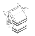
図1は、本発明を適用した実施形態に係るインクジェット方式のプリンタ(インクジェット記録装置)IJRAの主要部の構成を示す外観斜視図である。本実施形態に係るインクジェット方式のプリンタは、図1に示すように、記録媒体P(ここでは折畳可能な連続シート)の全幅にわたる範囲にインクを吐出するフルライン記録ヘッドIJHを配置した構成となっている。記録ヘッドIJHの記録ヘッドチップITの吐出口からはインクが所定のタイミングで記録媒体Pに向けて吐出される。
Preferred embodiments of the present invention will be described below with reference to the accompanying drawings.
(First embodiment)
<Basic Configuration of Inkjet Recording Apparatus (FIG. 1)>
FIG. 1 is an external perspective view showing a configuration of a main part of an ink jet printer (ink jet recording apparatus) IJRA according to an embodiment to which the present invention is applied. As shown in FIG. 1, the inkjet printer according to the present embodiment has a configuration in which a full-line recording head IJH that discharges ink is disposed over the entire width of a recording medium P (here, a foldable continuous sheet). It has become. Ink is ejected toward the recording medium P from the ejection port of the recording head chip IT of the recording head IJH at a predetermined timing.
このようにした記録ヘッドIJHを、記録媒体Pと相対的に移動させて記録を行う。本実施形態では、以下に説明する制御回路による制御によって搬送モータを駆動することにより、記録用紙Pが図1に示すVS方向(フルラインタイプでいう主走査方向)に搬送され、記録用紙P上に画像記録がなされる。図1において、5018は搬送ローラである。5019は排出側のローラであり、搬送ローラ5018と共に記録媒体Pを記録位置に保持すると共に、駆動モータ(不図示)によって駆動される搬送ローラ5018に連動して記録媒体Pを矢印VS方向に搬送する。
The recording head IJH thus configured is moved relative to the recording medium P to perform recording. In the present embodiment, the recording paper P is conveyed in the VS direction shown in FIG. 1 (main scanning direction in the full-line type) by driving the conveyance motor under the control of the control circuit described below. An image is recorded. In FIG. 1,
なお、記録ヘッドIJHには不図示のインク供給チューブが接続され、インクジェット記録素子からインクが吐出される。本例のインクジェット記録素子は、インク吐出口に連通する内部(液路)に、インク吐出に利用される熱エネルギーを発生する発熱素子(電気・熱エネルギー変換体)が設けられている。 An ink supply tube (not shown) is connected to the recording head IJH, and ink is ejected from the ink jet recording element. In the ink jet recording element of this example, a heating element (electric / thermal energy converter) that generates thermal energy used for ink ejection is provided in the interior (liquid path) communicating with the ink ejection port.
記録ヘッドIJHは、記録を行わないときに、不図示のキャッピング手段のキャップ部によってインク吐出口面が密閉されることにより、インク溶剤の蒸発に起因するインクの固着、或いは塵埃等の異物の付着等による目詰まりが防止される。また、キャッピング手段のキャップ部は、使用頻度の低いインク吐出口の吐出不良や目詰まりを解消するための空吐出(予備吐出)、つまりインク吐出口から、画像の記録に寄与しないインクをキャップ部に向かって吐出させるために利用することができる。また、キャッピング状態のキャップ部の内部に、不図示のポンプによって発生させた負圧を導入し、記録ヘッドIJHのインク吐出口から、画像の記録に寄与しないインクをキャップ部内に吸引排出させて、吐出不良を起こしたインク吐出口を回復させることもできる。また、キャップ部の隣接位置に、不図示のブレード(拭き部材)を配置することにより、記録ヘッドIJHにおけるインク吐出口の形成面をクリーニング(ワイピング)することも可能である。 When the recording head IJH does not perform recording, the ink discharge port surface is sealed by a cap portion (not shown) of the capping unit, so that the ink sticks due to evaporation of the ink solvent or the adhering foreign matter such as dust. Clogging due to such as is prevented. Further, the cap portion of the capping means is a cap portion for discharging ink that does not contribute to image recording from the ink discharge port (preliminary discharge) for eliminating discharge defects and clogging of the ink discharge port that is not frequently used. It can be used for discharging toward the water. Further, a negative pressure generated by a pump (not shown) is introduced into the cap portion in the capping state, and ink that does not contribute to image recording is sucked and discharged into the cap portion from the ink discharge port of the recording head IJH. It is also possible to recover the ink ejection port that caused the ejection failure. Further, by disposing a blade (wiping member) (not shown) at a position adjacent to the cap portion, it is possible to clean (wipe) the formation surface of the ink discharge port in the recording head IJH.
なお、図1では、記録媒体Pとして折畳可能な連続シートを図示したが、カットシートであっても何ら問題ない。また、1つのフルライン記録ヘッドIJHが備えられた構成を図示したが、高画質記録や高速記録のために、同じ構成のフルライン記録ヘッドを例えば2個備えるような構成としても良い。 In FIG. 1, a foldable continuous sheet is illustrated as the recording medium P, but there is no problem even if it is a cut sheet. In addition, although a configuration including one full line recording head IJH is illustrated, a configuration in which, for example, two full line recording heads having the same configuration are provided for high-quality recording and high-speed recording.
<記録ヘッドの基本構成(図2)>
図2は、上述した記録ヘッドIJHの要部の構成例を示す分解斜視図である。記録ヘッドIJHは、インクを加熱するための複数のヒータ(発熱素子)22が形成された基板であるヒータボード23と、このヒータボード23の上に被せられる天板24と、を主要素として構成される。天板24には複数の吐出口25が形成されており、各吐出口25の後方には、各吐出口25に連通するトンネル状の液路26が形成されている。各液路26は、その後方において1つのインク液室に共通に接続されている。そして、インク液室にはインク供給口を介してインクが供給され、このインクがインク液室から各液路26に供給される。吐出口25は、インクの吐出が可能な吐出口を形成する。
<Basic configuration of recording head (FIG. 2)>
FIG. 2 is an exploded perspective view illustrating a configuration example of a main part of the above-described recording head IJH. The recording head IJH includes a
ヒータボード23と天板24は、図2に示すように、各液路26に対応した位置に各ヒータ22が位置するように組み立てられる。図2においては、吐出口25、ヒータ22、及び液路26が4つずつ代表的に示されており、ヒータ22は、それぞれの液路26に対応して1つずつ配置される。そして、図2に示すように組み立てられた記録ヘッドIJHは、ヒータ22に所定の駆動パルスが供給されることにより、そのヒータ22上のインクが沸騰して気泡を形成し、この気泡の体積膨張によりインクが吐出口25から押し出されて吐出される。
As shown in FIG. 2, the
なお、本発明を適用可能なインクジェット記録方式は、図2に示したような発熱素子(ヒータ)を使用したバブルジェット(登録商標)方式に限られるものではない。例えば、ピエゾ素子による機械的圧力を利用してインクを吐出するインクジェット方式にも本発明を適用することができる。例えば、インク滴を連続噴射して粒子化するコンティニュアス型の場合には荷電制御型や発散制御型等がある。また、必要に応じてインク滴を吐出するオンデマンド型の場合には、ピエゾ振動素子の機械的振動によりオリフィスからインク滴を吐出する圧力制御方式等にも適用可能である。このように、種々のインクジェット記録素子を備えた記録ヘッドに対して本発明は適用可能である。 The ink jet recording system to which the present invention can be applied is not limited to the bubble jet (registered trademark) system using a heating element (heater) as shown in FIG. For example, the present invention can be applied to an ink jet system that ejects ink using mechanical pressure by a piezoelectric element. For example, in the case of a continuous type in which ink droplets are continuously ejected into particles, there are a charge control type and a divergence control type. Further, in the case of an on-demand type that ejects ink droplets as necessary, it can also be applied to a pressure control system that ejects ink droplets from an orifice by mechanical vibration of a piezoelectric vibration element. As described above, the present invention is applicable to a recording head including various ink jet recording elements.
<インクジェット記録装置の制御構成(図3)>
図3は、本実施形態に係るインクジェット方式のプリンタにおける制御系の構成例を示すブロック図である。図3において、31は画像データ入力部、32は操作部、33は各種処理を行うCPU部、34は各種データを記憶する記憶媒体である。記憶媒体34のプリント情報格納メモリには、記録媒体の主に種類に関する情報34a、プリントに用いるインクに関する情報34b、記録時の温度、湿度等の環境に関する情報34cが格納される。また、記憶媒体34には、各種制御プログラム群34dが格納される。更に、35はRAM、36は画像データ処理部、37は画像出力を行う画像記録部、38は各種データを転送するバス部である。
<Control Configuration of Inkjet Recording Apparatus (FIG. 3)>
FIG. 3 is a block diagram illustrating a configuration example of a control system in the ink jet printer according to the present embodiment. In FIG. 3, 31 is an image data input unit, 32 is an operation unit, 33 is a CPU unit for performing various processes, and 34 is a storage medium for storing various data. The print information storage memory of the
更に詳述すると、画像データ入力部31は、スキャナやデジタルカメラ等の画像入力機器からの多値画像データやパーソナルコンピュータのハードディスク等に保存されている多値画像データを入力する。操作部32は、各種パラメータの設定及び記録開始を指示する各種キーを備えている。
More specifically, the image
CPU33は、記憶媒体中の各種プログラムに従って本プリンタ全体を制御する。記憶媒体34は、制御プログラムやエラー処理プログラムに従って本プリンタを動作させるためのプログラム等を格納している。本例の動作は、全てこのプログラムに従う動作である。このようなプログラムを格納する記憶媒体34としては、ROM、FD、CD−ROM、HD、メモリカード、光磁気ディスク等を用いることができる。RAM35は、記憶媒体34中の各種プログラムのワークエリア、エラー処理時の一時待避エリア、及び画像処理時のワークエリアとして用いられる。また、RAM35は、記憶媒体34の中の各種テーブルをコピーした後、そのテーブルの内容を変更し、この変更したテーブルを参照しながら画像処理を進めることも可能である。
The
画像データ処理部36は、画像データ入力部31で入力されたデータに対して、カラーマッチング処理、色分解処理、出力γ補正、解像度変換等の各種画像処理を適用した後、入力された多値画像データをN値の画像データに各画素毎に量子化する。次いで、量子化された各画素が示す階調値"N"に基づいてその階調値に対応するドット配置パターンを選択する。このドット配置パターンはドットの記録の有無を示す2値のパターンであるので、ドット配置パターンの選択によって2値の吐出データを得ることができる。
The image
このように、画像データ処理部36は、入力された多値画像データをN値化処理した後、そのN値の画像データに基づいて2値の吐出データを作成する。例えば8bit(256階調)で表現される多値画像データが画像データ入力部31に入力される場合、画像データ処理部36においては出力する画像データの階調値を25値に量子化する。次いで、画像データ処理部36では、25値の画像データにドット配置パターンが割り当てられ、これにより、インクの吐出・非吐出を示す2値の吐出データが作成される。その後、2値の吐出データが複数の吐出口列に分配され、各吐出口列の吐出口に対応する2値の吐出データが決定される。なお、本例においては、入力階調画像データのN値化処理に多値誤差拡散法を用いるが、これに限らず、平均濃度保存法やディザマトリックス法等、任意の中間調処理方法を用いることができる。また、画像データ処理部36は、多値画像データから最終的に2値の吐出データを作成できればよく、上述したようにN値化処理を介在させることは必須ではない。例えば、画像データ処理部36に入力された多値画像データを直接2値の吐出データに変換するような2値化処理を行っても良い。
As described above, the image
画像記録部37は、画像データ処理部36で作成された2値の吐出データに基づいて、対応する吐出口25からインクを吐出して、記録媒体上にドット画像を形成する。バスライン38は、本装置内のアドレス信号、データ、制御信号等を伝送する。
The
<ヘッド構成(図4〜図6)>
図4は、記録ヘッドIJHの概略構成を示す図であり、記録ヘッドIJHに配置される複数の記録ヘッドチップ及び各記録ヘッドチップの吐出口列を示している。本実施形態の記録ヘッドIJHは、吐出口列方向の長さが比較的短いチップ状の構成部品(以下、記録チップという)41〜46を備える。
<Head configuration (FIGS. 4 to 6)>
FIG. 4 is a diagram showing a schematic configuration of the recording head IJH, and shows a plurality of recording head chips arranged in the recording head IJH and an ejection port array of each recording head chip. The recording head IJH of the present embodiment includes chip-shaped components (hereinafter referred to as recording chips) 41 to 46 having a relatively short length in the ejection port array direction.
記録ヘッドIJHは、一列あたり一色分のインクを吐出する吐出口列(A列、B列、C列、D列)を略平行に複数列配した記録チップ41〜46を、吐出口列方向に複数つなげてなる。各吐出口列は、直線上に吐出口が配置されたものであり、図中では、例えば記録チップ41であれば41A、41B、41C、41Dのように記載する。
The recording head IJH has
本実施形態では、記録チップ41〜46を吐出口列方向に千鳥状に配置配列することによって、長尺の記録ヘッドIJHを形成している。すなわち、記録チップとそれにつなげる記録チップとを吐出口列方向と略直交する方向(主走査方向)にずらして配置するとともに、吐出口列方向において吐出口列が一部オーバーラップするように構成されている。 In the present embodiment, the long recording head IJH is formed by arranging the recording chips 41 to 46 in a staggered manner in the discharge port array direction. That is, the recording chip and the recording chip connected to the recording chip are arranged so as to be shifted in a direction substantially orthogonal to the ejection port array direction (main scanning direction), and the ejection port arrays partially overlap in the ejection port array direction. ing.
各記録チップ41〜46の吐出口列の構成はいずれも同じであることから、記録チップ41を例にその構成を説明する。記録チップ41は、上述の通り、4列の吐出口列(41A、41B、41C、41D)を有しており、各列とも1200dpiの解像度で配列された複数の吐出口を有している。
Since the configuration of the ejection port arrays of the
また、各記録チップ41〜46に設けられた、吐出口列であるA列、B列、C列、D列は、記録ヘッドIJHにおいて、それぞれの吐出口列毎にそれぞれ同一色(種類)のインクを吐出する。ここでは、記録チップ41〜46のそれぞれにおいて、A列はイエロー(Y)、B列はマゼンタ(M)、C列はシアン(C)、D列はブラック(Bk)のインクを記録するように構成されている。
Further, the A, B, C, and D columns, which are the ejection port arrays provided in the
なお、本実施形態では、各記録チップが4列の吐出口列から構成され、4色のインクで記録する場合を述べているが、各記録チップの吐出口列の数、インクの数は任意とすることができる。例えば、図5に示すように、隣り合う記録チップ51と記録チップ52とが6列の吐出口列からそれぞれ構成され、C、M、Y、Bk、LC(淡シアン)、LM(淡マゼンタ)の6色のインクで記録するような構成でも良い。他にも、レッド、ブルー、グリーン等、淡グレー等、特色が含まれていても良い。
In the present embodiment, each recording chip is composed of four ejection port arrays and recording is performed with four colors of ink. However, the number of ejection port arrays and the number of inks in each recording chip are arbitrary. It can be. For example, as shown in FIG. 5,
なお、上述の例では、吐出口列がインクの色に応じて入れ子の状態となったヘッド構成の場合で説明したが、つなぎ部の吐出口列間の距離が異なる関係が含まれる構成であれば、入れ子の状態である必要はなく、本発明を適用可能である。更に言うと、つなぎ部を構成する吐出口列同士は、同一の記録ヘッド内でもよいし、同一でない記録ヘッド同士であっても構わない。加えて、1記録ヘッド内における記録チップの個数、すなわち、つなぎ部に相当する部分の数は任意であってよい。 In the above example, the description has been given of the case of the head configuration in which the ejection port arrays are nested according to the color of the ink. However, the configuration may include a relationship in which the distance between the ejection port arrays in the joint portion is different. For example, it is not necessary to be in a nested state, and the present invention can be applied. Furthermore, the ejection port arrays constituting the connecting portion may be in the same recording head or may be non-identical recording heads. In addition, the number of recording chips in one recording head, that is, the number of portions corresponding to the connecting portion may be arbitrary.
図6は、隣り合う記録チップ41と記録チップ42の吐出口列の状態を詳細に表わした模式図である。記録チップ41と記録チップ42とは、所定の吐出口が吐出口列向にオーバーラップするように配置されている。このオーバーラップ部分を、つなぎ部と称する。一方、つなぎ部以外の部分を非つなぎ部と称する。
FIG. 6 is a schematic diagram showing in detail the state of the ejection port arrays of the
このように配置することによって、記録を行った際に、記録チップ同士のつなぎ目の位置に対応する記録媒体上の白スジの発生を防止している。本実施形態では、記録チップ41と記録チップ42とで、吐出口列方向の端部に位置する吐出口から、吐出口列方向に32個分の吐出口が互いに重なるように構成されている(図は一部省略)。
By arranging in this way, white stripes on the recording medium corresponding to the position of the joint between the recording chips are prevented when recording is performed. In the present embodiment, the
なお、図示例では、つなぎ部においてオーバーラップする部分の吐出口同士が、同一記録ライン上となる場合を説明したが、必ずしもこの構成である必要はない。例えば、それぞれ半ピッチずつずらすことで、つなぎ部の記録解像度を2倍に高めた構成や、つなぎ部の吐出口の解像度が位置によって変わっているような特殊な構成であっても、本発明の範疇に含まれれば何ら問題なく本発明を適用可能である。 In the illustrated example, the case has been described in which the discharge ports of the overlapping portions in the connecting portion are on the same recording line, but this configuration is not necessarily required. For example, even in a configuration in which the recording resolution of the joint portion is doubled by shifting each half pitch, or a special configuration in which the resolution of the discharge port of the joint portion changes depending on the position, The present invention can be applied without any problem as long as it is included in the category.
<画像データ処理方法(図8)>
図8は、本実施形態におけるつなぎ部に対する画像データ処理を説明するブロック図である。この画像データ処理の流れに従って、つなぎ部における各吐出口列の記録データ(2値の吐出データ)が決定される。なお、ここでの画像データ処理は、CPU33の制御の下で、画像データ処理部36において実行される。
<Image Data Processing Method (FIG. 8)>
FIG. 8 is a block diagram for explaining image data processing for the connecting portion in the present embodiment. According to the flow of this image data processing, the recording data (binary discharge data) of each discharge port array in the connecting portion is determined. Note that the image data processing here is executed in the image
まず、ステップS101では、入力されたカラー画像を各インク色へと色分解した後の多値データに対して、つなぎ部の吐出口列へのデータ分配が適用される。色分解処理は、別途設けた色分解用ルックアップテーブル(LUT)を参照して行われる。ここでは、多値データが、データ分配後多値データ(つなぎ部X)とデータ分配後多値データ(つなぎ部Y)の2つに分配される。つなぎ部X、つなぎ部Yの組み合わせとしては、例えば、吐出口列41Aと42A、41Bと42B、41Cと42C、41Dと42Dのように、同色のインクの吐出を担う、つなぎ部を構成する組の吐出口列を表わしている。その他の吐出列の組についても同様である。
First, in step S101, data distribution to the discharge port array of the joint portion is applied to the multivalued data after color separation of the input color image into each ink color. The color separation processing is performed with reference to a separately provided color separation lookup table (LUT). Here, the multi-value data is distributed into two: multi-value data after data distribution (connecting portion X) and multi-value data after data distribution (connecting portion Y). As a combination of the connecting portion X and the connecting portion Y, for example, a set constituting a connecting portion that is responsible for discharging the same color ink, such as the
ステップS102では、データ分配後多値データ(つなぎ部X)Aに対して所定のフィルタF_mにてフィルタ処理を行い、下式(1)のようにAfを算出する。
Af=A*F_m・・・(1)
:コンボリューション
In step S102, filter processing is performed on the multi-valued data (joint portion X) A after data distribution using a predetermined filter F_m, and Af is calculated as in the following equation (1).
Af = A * F_m (1)
: Convolution
本実施形態では、フィルタF_mとして、下式(2)のような2次元のガウシアンフィルタを用いて、フィルタ係数の設定を行う。式(2)において、(σx,σy)は2次元正規分布の標準偏差、ρはx,yの相関係数である。 In the present embodiment, a filter coefficient is set using a two-dimensional Gaussian filter such as the following expression (2) as the filter F_m. In Expression (2), (σ x , σ y ) is a standard deviation of a two-dimensional normal distribution, and ρ is a correlation coefficient of x and y.

本実施形態では、フィルタ係数を、つなぎ部を構成する吐出口列間の距離に応じて、設定する。具体的に、つなぎヘッドにおける記録チップ41と42を一例として以下に説明する。つなぎ部を構成する、吐出口列41Aと42A、41Bと42B、41Cと42C、41Dと42Dのそれぞれにおいて、吐出口列間の列間距離が離れるほど(距離が大きいほど)、標準偏差(σx,σy)が大きな値となるように設定する。例えば、以下のような設定値とすることができる。また、このときのフィルタサイズは5×5とする。
41Aと42A :σx=σy=0.5
41Bと42B :σx=σy=0.5
41Cと42C :σx=σy=1.5
41Dと42D :σx=σy=1.5
このときのフィルタ係数を図9〜図10に示す。
In the present embodiment, the filter coefficient is set according to the distance between the discharge port arrays constituting the connecting portion. Specifically, the recording chips 41 and 42 in the connecting head will be described below as an example. In each of the
41A and 42A: σ x = σ y = 0.5
41B and 42B: σ x = σ y = 0.5
41C and 42C: σ x = σ y = 1.5
41D and 42D: σ x = σ y = 1.5
The filter coefficients at this time are shown in FIGS.
ステップS103では、データ分配後多値データ(つなぎ部X)に対して2値化処理を適用する。2値化の手法は特に問わないが、具体的には、例えばR.Floyd等による誤差拡散法を用いる(非特許文献1を参照)。 In step S103, binarization processing is applied to the multi-valued data after data distribution (connecting portion X). The binarization method is not particularly limited. Specifically, for example, an error diffusion method by R. Floyd or the like is used (see Non-Patent Document 1).
その後、ステップS104では、ステップS103で得られた2値データに対してローパスフィルタ処理を適用する。ここでの出力は、以降説明する、データ分配後多値データ(つなぎ部Y)から2値データを求める際に用いられるものであって、データ分配後多値データ(つなぎ部Y)のドット配置を決める上で、ドットが打たれやすいか否かの情報となる。 Thereafter, in step S104, low-pass filter processing is applied to the binary data obtained in step S103. The output here is used when binary data is obtained from multi-value data after data distribution (connecting portion Y), which will be described later, and the dot arrangement of multi-value data after data distribution (connecting portion Y). This is information about whether or not dots are likely to be hit.
具体的に、ステップS104では、ステップS103で得られる2値データBに対して所定のローバスフィルタLPF_bにてフィルタ処理を行い、下式(3)のようにBfを算出する。
Bf=A*LPF_b・・・(3)
Specifically, in step S104, the binary data B obtained in step S103 is filtered by a predetermined low-pass filter LPF_b, and Bf is calculated as in the following equation (3).
Bf = A * LPF_b (3)
本実施形態におけるLPF_bの係数も、上述のF_mと同様、つなぎ部を構成する吐出口列間の距離に応じて設定する。本実施形態では、F_mとLPF_bを同じとするが、異なる係数であっても良い。 The coefficient of LPF_b in the present embodiment is also set according to the distance between the ejection port arrays constituting the connecting portion, as in the case of F_m described above. In this embodiment, F_m and LPF_b are the same, but different coefficients may be used.
ここで、フィルタで指定する標準偏差(σx,σy)の大小における効果について以下説明する。標準偏差(σx,σy)を大きくするほど、ガウシアンフィルタの強度が高まり、効果として、データ分配後多値データ(つなぎ部X)とデータ分配後多値データ(つなぎ部Y)とのドット配置の関係が、排他とならない(排他関係が弱い)。すなわち、両者のドットが重なり合うようになる。このような理由から、つなぎ部での吐出口列の列間距離が大きくつなぎスジが発生しやすい吐出口列間に対しては、標準偏差(σx,σy)を大きくすることで、プリンタ変動(ズレ)に対するロバスト性を高くすることができる。 Here, the effect on the magnitude of the standard deviation (σ x , σ y ) specified by the filter will be described below. As the standard deviation (σ x , σ y ) increases, the strength of the Gaussian filter increases. Placement relationship is not exclusive (exclusion relationship is weak). That is, the two dots overlap. For these reasons, by increasing the standard deviation (σ x , σ y ) for the discharge port arrays where the distance between the discharge port arrays at the connection part is large and the streak lines are likely to occur, the printer Robustness against fluctuation can be increased.
一方、標準偏差(σx,σy)を小さくするほど、ガウシアンフィルタの強度が低くなり、効果として、データ分配後多値データ(つなぎ部X)とデータ分配後多値データ(つなぎ部Y)とのドット配置の関係が、排他となる(排他関係が強い)。すなわち、両者のドットが重複しないようになる。このことは、一般的なつなぎ部マスクのようにドット同士が排他となることを意味する。このような理由から、つなぎ部での吐出口列の列間距離が小さくつなぎスジが発生し難い吐出口列間に対しては、標準偏差(σx,σy)を小さくすることで、プリンタ変動(ズレ)に対するロバスト性を重視するのではなく、つなぎ部での画質を高くすることができる。 On the other hand, the smaller the standard deviation (σ x , σ y ), the lower the strength of the Gaussian filter. As an effect, multi-value data after data distribution (connecting portion X) and multi-value data after data distribution (connecting portion Y) The dot arrangement relationship is exclusive (the exclusive relationship is strong). That is, the two dots do not overlap. This means that dots are mutually exclusive like a general joint mask. For this reason, by reducing the standard deviation (σ x , σ y ) for the discharge port arrays where the distance between the discharge port arrays at the connection portion is small and the connection streak is difficult to occur, the printer Rather than emphasizing robustness against fluctuations, it is possible to increase the image quality at the joint.
なお、フィルタの形状は正方形でなく、長方形であっても良い。つなぎ部のズレの発生の程度によって、非等方的な形状としてもよい。 Note that the shape of the filter is not square but may be rectangular. An anisotropic shape may be used depending on the degree of occurrence of misalignment of the joint portion.
ステップS105では、つなぎ部Yの入力データ補正を行う。具体的には、データ分配後多値データ(つなぎ部Y)に対して、ステップS102で得られた2値データAfを加算し、ステップS104で得られた2値データBfを減算することで得られる。 In step S105, the input data of the joint Y is corrected. Specifically, it is obtained by adding the binary data Af obtained in step S102 and subtracting the binary data Bf obtained in step S104 to the post-data distribution multi-value data (connecting portion Y). It is done.
ステップS106では、ステップS105で得られた多値データに対して2値化処理を適用し、2値データ(つなぎ部Y)を得る。 In step S106, a binarization process is applied to the multi-value data obtained in step S105 to obtain binary data (joint portion Y).
以上のような手順でつなぎ部を構成する2値データが得られ次第、記録ヘッドにデータが転送され、記録が行われる。 As soon as the binary data constituting the connecting portion is obtained by the procedure as described above, the data is transferred to the recording head and recording is performed.
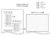
図12は、本実施形態におけるつなぎ部の2値パターンと、それら2値パターン間のクロススペクトルの一例を示した図である。図中(a)は吐出口列41A並びに41B、図中(b)は吐出口列42A並びに42B、図中(c)は吐出口列41C、図中(d)は吐出口列42C、図中(e)は吐出口列41D、図中(f)は吐出口列42Dにおける2値パターンの一例を表している。なお、図12は模式的に図示したものであり、厳密に再現しているわけではない。
FIG. 12 is a diagram illustrating an example of a binary pattern of a connecting portion and a cross spectrum between the binary patterns in the present embodiment. In the figure, (a) is the
このとき、上述のように標準偏差を変化させることにより、図中(a)、(b)ではパターン間が完全排他(高周波排他、低周波排他)、図中(e)、(f)ではロバスト性を重視したパターン関係(高周波ランダム、低周波排他)となっている。図中(c)、(d)については、それらの中間のパターン関係である。 At this time, by changing the standard deviation as described above, the patterns are completely exclusive (high frequency exclusive, low frequency exclusive) in the diagrams (a) and (b), and robust in the diagrams (e) and (f). It is a pattern relationship (high frequency random, low frequency exclusive) that emphasizes the nature. In the figure, (c) and (d) are intermediate pattern relationships between them.
また、図12の下方に示すグラフは、クロススペクトル算出した際のradial frequencyと位相差をグラフ化したものである。右のグラフになるほど、高周波側の位相差が低い、すなわちパターン間の排他関係が弱くなり、メカズレに対するロバスト性を重視したパターン同士となることを表わしている。 The graph shown in the lower part of FIG. 12 is a graph showing the radial frequency and the phase difference when the cross spectrum is calculated. The graph on the right indicates that the phase difference on the high frequency side is lower, that is, the exclusive relationship between patterns becomes weaker, and the patterns emphasize the robustness against mechanical misalignment.
なお、以上の説明においては、本発明の特徴的な部分である、つなぎ部における画像データ処理方法について記録チップ41と記録チップ42でのつなぎ部について代表として述べたが、その他のチップ間においても同様な処理を適用可能である。また、つなぎ部以外の画像データ処理方法に関しては、従来技術と同様に処理すればよい。
In the above description, the image data processing method in the connecting portion, which is a characteristic part of the present invention, has been described as a representative of the connecting portion between the
<実施例>
以下、具体的な実施例を示す。記録に際しては、上述した図1と同様の構成のプリンタを用い、図4で示した記録ヘッドIJHを備えた。1つの吐出口からの1回の吐出量が2.8plとなるように記録ヘッドを駆動した。色材を含有するインクとしては、市販のインクジェットプリンタPIXUS iP7100(キヤノン株式会社製)用のインクBCI−7を用いた。なお、各吐出口列とインクの色の関係は、上述の通り、記録チップ41〜46のそれぞれにおいて、A列はイエロー(Y)、B列はマゼンタ(M)、C列はシアン(C)、D列はブラック(Bk)のインクを記録するようにインクを充填した。記録媒体P5としては、インクジェット専用フォト光沢紙(プロフォトペーパー、PR−101:キヤノン株式会社製)を用意した。
<Example>
Specific examples will be described below. For recording, a printer having the same configuration as that of FIG. 1 described above was used, and the recording head IJH shown in FIG. 4 was provided. The recording head was driven so that the amount of ejection from one ejection port was 2.8 pl. As an ink containing a coloring material, a commercially available ink BCI-7 for an inkjet printer PIXUS iP7100 (manufactured by Canon Inc.) was used. As described above, the relationship between the ejection port arrays and the ink colors is as follows. In each of the recording chips 41 to 46, the A column is yellow (Y), the B column is magenta (M), and the C column is cyan (C). , D row was filled with ink so as to record black (Bk) ink. As the recording medium P5, an inkjet-dedicated photo glossy paper (Pro Photo Paper, PR-101: manufactured by Canon Inc.) was prepared.
更に詳細には、インク滴の吐出駆動周波数を8kHzとし、記録解像度としては主走査方向(記録媒体の搬送方向)が1200dpi、副走査方向(吐出口列方向)が1200dpiとした。また、テスト画像のデータとして、記録デューティを振った階調パッチ画像データ(0〜255までを17階調分に分けたもの)を用意した。また、上記17種のデューティ以外の様々なディーティも含んだ写真調の画像データを用意した。このとき、ある一つの階調においては、各インク色とも同じデューティとした。 More specifically, the ink droplet ejection drive frequency was 8 kHz, and the recording resolution was 1200 dpi in the main scanning direction (printing medium conveyance direction) and 1200 dpi in the sub-scanning direction (ejection port array direction). Also, as test image data, gradation patch image data (recording 0 to 255 divided into 17 gradations) with a recording duty was prepared. Also, photographic image data including various duties other than the above 17 types of duty were prepared. At this time, the duty is the same for each ink color in a certain gradation.
以上のような設定条件下において、用意したパッチ画像データを、記録ヘッドと記録媒体との一度の相対移動(主走査)で記録した。その際、パッチ画像データの2値化処理及びデータ分配処理は図8の流れに従って実行し、インクを吐出して上記パッチ画像を記録した。 Under the set conditions as described above, the prepared patch image data was recorded by one relative movement (main scanning) between the recording head and the recording medium. At that time, the binarization processing and data distribution processing of the patch image data were executed according to the flow of FIG. 8, and ink was ejected to record the patch image.
その結果、いずれの階調においても、記録チップ間でのつなぎスジはほとんど視認されず、画質劣化の見られない満足のいく画質の画像が記録できた。図13は、この記録によって得られたパッチ画像のうち、中間調の一階調分の印字画像の様子の概略図を、ヘッド構成の図と合わせて示したものである。図13から分かるように、上述の記録方法によれば、記録チップ間でのつなぎスジの発生を抑制できる。 As a result, in any gradation, the connecting streak between the recording chips was hardly visually recognized, and a satisfactory image quality image with no image quality degradation could be recorded. FIG. 13 shows a schematic view of a print image for one gradation of halftones in a patch image obtained by this recording, together with a head configuration diagram. As can be seen from FIG. 13, according to the above-described recording method, it is possible to suppress the generation of connecting stripes between the recording chips.
次に、上記17種のデューティ以外の様々なディーティを含んだ写真調の画像データを記録した。その際も、画像データの2値化処理及びデータ分配処理は図8の流れに従って実行した。この場合でも、上記パッチ画像を記録したときと同様、記録チップ間でのつなぎスジはほとんど視認されず、画質劣化の少ない満足のいく画質の画像を記録することができた。 Next, photographic image data including various duties other than the 17 types of duty was recorded. Also at that time, the binarization processing and data distribution processing of the image data were executed according to the flow of FIG. Even in this case, as in the case of recording the patch image, the connecting stripes between the recording chips were hardly visually recognized, and an image with satisfactory image quality with little image quality deterioration could be recorded.
<比較例>
本発明の実施例と比較するための比較例を説明する。本比較例においても、図4で示したものと同様の記録ヘッドを用いるが、上述の式(1)、(3)のフィルタ処理の際に用いる標準偏差の値が、つなぎ部を構成する吐出口列41Aと42A、41Bと42B、41Cと42C、41Dと42Dのいずれにおいても、σx=σy=0.5とする。このときのフィルタサイズは5×5とし、フィルタ係数を図9に示したものとする。
<Comparative example>
The comparative example for comparing with the Example of this invention is demonstrated. In this comparative example, a recording head similar to that shown in FIG. 4 is used. However, the standard deviation value used in the filter processing of the above-described equations (1) and (3) is the discharge constituting the connecting portion. In any of the
以下、具体的な比較例を示す。記録に際しての諸条件は上述の内容以外は、実施例と同じである。すなわち、上述した図1と同様の構成のプリンタを用い、図4で示した記録ヘッドIJHを備えた。1つの吐出口からの1回の吐出量が2.8plとなるように記録ヘッドを駆動した。色材を含有するインクとしては、市販のインクジェットプリンタPIXUS iP7100(キヤノン株式会社製)用のインクBCI−7を用いた。記録媒体Pとしては、インクジェット専用フォト光沢紙(プロフォトペーパー、PR−101:キヤノン株式会社製)を用意した。 A specific comparative example is shown below. Various conditions for recording are the same as those in the example except for the contents described above. That is, the printer having the same configuration as that of FIG. 1 described above was used, and the recording head IJH shown in FIG. 4 was provided. The recording head was driven so that the amount of ejection from one ejection port was 2.8 pl. As an ink containing a coloring material, a commercially available ink BCI-7 for an inkjet printer PIXUS iP7100 (manufactured by Canon Inc.) was used. As the recording medium P, ink-dedicated photo glossy paper (Pro Photo Paper, PR-101: manufactured by Canon Inc.) was prepared.
更に詳細には、インク滴の吐出駆動周波数を8kHzとし、記録解像度としては主走査方向(記録媒体の搬送方向)が1200dpi、副走査方向(吐出口列方向)が1200dpiとした。また、テスト画像のデータとして、記録デューティを振った階調パッチ画像データ(0〜255までを17階調分に分けたもの)を用意した。このとき、ある一つの階調においては、各インク色とも同じデューティとした。また、上記17種のデューティ以外の様々なディーティも含んだ写真調の画像データを用意した。 More specifically, the ink droplet ejection drive frequency was 8 kHz, and the recording resolution was 1200 dpi in the main scanning direction (printing medium conveyance direction) and 1200 dpi in the sub-scanning direction (ejection port array direction). Also, as test image data, gradation patch image data (recording 0 to 255 divided into 17 gradations) with a recording duty was prepared. At this time, the duty is the same for each ink color in a certain gradation. Also, photographic image data including various duties other than the above 17 types of duty were prepared.
以上のような設定条件下において、用意したパッチ画像データを、記録ヘッドと記録媒体との一度の相対移動(主走査)で記録した。 Under the set conditions as described above, the prepared patch image data was recorded by one relative movement (main scanning) between the recording head and the recording medium.
その結果、ほとんどの階調、特に中間調から高濃度部にかけて、記録ヘッドにおける記録チップ間でのつなぎスジが視認され、画質が劣化した満足のいかない画質の画像となった。図14は、この記録によって得られたパッチ画像のうち、中間調の一階調分の印字画像の様子の概略図を、ヘッド構成の図と合わせて示したものである。図14から分かるように、本比較例では、記録チップ間でのつなぎスジの発生が確認される。なお、図面上はつなぎスジの見え方を概略図として示したものであって、実際の見え方を必ずしも厳密に再現しているわけではない。 As a result, from almost all gradations, particularly from the halftone to the high density portion, the connecting streaks between the recording chips in the recording head were visually recognized, resulting in an unsatisfactory image quality with degraded image quality. FIG. 14 shows a schematic view of a print image for one gradation of halftones in a patch image obtained by this recording, together with a head configuration diagram. As can be seen from FIG. 14, in this comparative example, the generation of connecting stripes between the recording chips is confirmed. In the drawings, the appearance of the connecting stripes is shown as a schematic diagram, and the actual appearance is not necessarily reproduced exactly.
次に、上記17種のデューティ以外の様々なディーティを含んだ写真調の画像データを記録した。この場合も、上記パッチ画像を記録したときと同様、主走査方向に対する記録チップ間でのつなぎスジが一部視認され、画質が劣化した満足のいかない画質の画像となってしまった。 Next, photographic image data including various duties other than the 17 types of duty was recorded. In this case as well, as in the case of recording the patch image, a part of the connecting stripes between the recording chips in the main scanning direction was visually recognized, resulting in an unsatisfactory image quality with degraded image quality.
以上説明したように、主走査方向における吐出口列間の距離が大きくなるつなぎ部ほど、つなぎ部で印字するパターン間同士の配置関係の排他性を崩し、ドットの重複を認めるようにパターンを決めるようにした。これにより、メカ変動等の影響によって発生し易いつなぎスジの発生を抑制し、高品位な記録を得ることができた。言うまでもなく、記録装置のズレの状態や、つなぎヘッド構成における吐出口列間の距離はプリンタ構成や環境によって変動するものであって、それに合わせて、適宜最適な構成とすればよい。 As described above, as the connecting portion where the distance between the ejection port arrays in the main scanning direction becomes larger, the exclusivity of the arrangement relationship between the patterns printed at the connecting portion is broken, and the pattern is determined so as to recognize the overlap of dots. I made it. As a result, it was possible to suppress the generation of connecting stripes that are likely to occur due to the influence of mechanical fluctuations, and to obtain high-quality records. Needless to say, the displacement state of the recording apparatus and the distance between the ejection port arrays in the connecting head configuration vary depending on the printer configuration and the environment, and an optimal configuration may be appropriately set according to the variation.
一方、主走査方向における吐出口列間の距離が小さいつなぎ部においては、メカ変動等の影響によるつなぎスジが発生し難いため、従来通り、つなぎ部で印字するパターン間同士の配置関係を排他とすることで、つなぎ部での画質を高画質化するようにすればよい。 On the other hand, at the connecting part where the distance between the ejection port arrays in the main scanning direction is small, a connecting line is hardly generated due to the influence of mechanical fluctuations. Thus, the image quality at the connecting portion may be improved.
なお、上述の実施形態では、1列ずつの吐出口列でつなぎ部が構成された例について説明したが、画質向上を目的として複数列でつなぎ部を構成するような形態においても、同様な構成を取ることができる。例えば、つなぎ部が3列で構成される場合においては、例えば、3列目のパターンを決定する際、1、2列目の吐出口列に打たれたドットとの排他関係を制御すればよい。 In the above-described embodiment, the example in which the connecting portion is configured by the ejection port array for each row has been described. However, the same configuration is applied to an embodiment in which the connecting portion is configured by a plurality of rows for the purpose of improving image quality. Can take. For example, in the case where the connecting portion is composed of three rows, for example, when determining the pattern of the third row, it is only necessary to control the exclusive relationship with the dots placed on the first and second discharge port rows. .
また、上述の実施形態では、つなぎ部のグラデーションマスクのない場合の例について述べたが、図8におけるデータ分配処理で出力される各多値データに対して、フルラインヘッドにおいて一般的に用いられるつなぎ部のマスク、例えば端部ほど打ち込み量が少なくなる、いわゆるグラデーション状のマスク等を適用した上で、本実施形態での処理を適用しても何ら問題ない。 In the above-described embodiment, an example in which there is no gradation mask at the joint portion has been described. However, the multiline data output by the data distribution processing in FIG. 8 is generally used in a full line head. There is no problem even if the processing in the present embodiment is applied after applying a mask at the joint portion, for example, a so-called gradation-like mask in which the amount of implantation is reduced toward the end portion.
(第2の実施形態)
第1の実施形態では、吐出口列のつなぎ部の位置が、いずれのインク色においても吐出口列方向において同一となるヘッド構成である記録ヘッドにおける形態を示したが、つなぎ部の位置は、それぞれのインク色毎に異なるようなヘッド構成である記録ヘッドであっても、本発明を適用することができる。
(Second Embodiment)
In the first embodiment, the form of the recording head having a head configuration in which the position of the connecting portion of the ejection port array is the same in the direction of the ejection port array in any ink color is shown. The present invention can be applied even to a recording head having a different head configuration for each ink color.
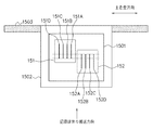
図15は、つなぎ部の位置がインク色毎に、すなわち、吐出口列131A〜131D、132A〜132D毎に異なるヘッド構成の概略図である。ヘッドの構成が異なる以外は、第1の実施形態と同様である。
FIG. 15 is a schematic diagram of a head configuration in which the position of the connecting portion is different for each ink color, that is, for each of the
また、吐出口列自体のヘッド構成は図4のように各吐出口列の端部が副走査方向に並んだ構成において、使用する吐出口を適宜制限することで、図15と同様に、つなぎ部の位置を、それぞれのインク色毎に異ならせたような構成であっても、何ら構わない。この方法を取ることで、汎用的な記録チップを流用できるという利点がある。 Further, the head configuration of the ejection port array itself is connected in the same manner as in FIG. 15 by appropriately limiting the ejection ports to be used in the configuration in which the ends of the ejection port arrays are arranged in the sub-scanning direction as shown in FIG. Even if the positions of the portions are different for each ink color, there is no problem. By taking this method, there is an advantage that a general-purpose recording chip can be diverted.
なお、つなぎ部の記録位置をずらすと、ヘッド構成がより大きくなってしまうため、例えば、つなぎスジが目立ち難い、イエローとマゼンタはつなぎ位置を同じとする等、一部の色のつなぎ部を同一とする場合もある。この場合においても、本発明の範疇であり、その他構成であっても何ら問題ない。 If the recording position of the connecting part is shifted, the head configuration becomes larger.For example, the connecting line is less noticeable, and the connecting part of some colors is the same, for example, yellow and magenta have the same connecting position. In some cases. Even in this case, it is within the scope of the present invention, and there is no problem with other configurations.
(第3の実施形態)
以上の実施形態においては、画像データを各インク色へと色分解した後の多値データに対して前記つなぎ部の吐出口列へのデータ分配を行い、分配された多値データを排他関係を制御しつつ2値の吐出データとする例を説明したが、画像データを各インク色へと色分解した後の多値データを2値の吐出データとし、2値の吐出データに対して排他関係を制御しつつつなぎ部の吐出口列へのデータ分配を行うようにしてもよい。すなわち、以上の実施形態においては、各つなぎ部に多値データを割り振り、2値化を適用する形態について説明したが、つなぎ部のドットパターン間の排他関係をつなぎ部のデータ分配マスクとして実装する形態をとることも可能である。
(Third embodiment)
In the above embodiment, data distribution is performed on the multi-value data after color separation of the image data into each ink color to the discharge port array of the connecting portion, and the distributed multi-value data is in an exclusive relationship. Although an example in which binary discharge data is used while being controlled has been described, multi-value data after color separation of image data into ink colors is set as binary discharge data and is exclusive to the binary discharge data. It is also possible to perform data distribution to the discharge port array of the connecting portion while controlling the above. That is, in the above embodiment, the multi-value data is allocated to each joint portion and binarization is applied. However, the exclusive relationship between the dot patterns of the joint portion is implemented as the data distribution mask of the joint portion. It can also take a form.
以下、本実施形態においても図4に示したヘッド構成を用い、つなぎ部を構成する。ここでは、代表として、記録チップ41と記録チップ42との間のつなぎ部において説明する。その他のつなぎ部に対する処理も同様である。
Hereinafter, also in the present embodiment, the head configuration shown in FIG. Here, as a representative, a description will be given at a connecting portion between the
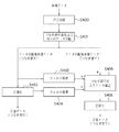
図16は、本実施形態におけるつなぎ部に対する画像データ処理のフローチャートである。ステップS301では、色分解後の多値データに対して2値化処理を適用する。2値化手法としては、誤差拡散法、INDEX展開法等、特に問わないが、ここでは、多値データを誤差拡散法によりN値データに量子化し、そのN値データにドット配置パターンを割り当てることで2値化する。 FIG. 16 is a flowchart of image data processing for the connecting portion in the present embodiment. In step S301, binarization processing is applied to the multivalued data after color separation. The binarization method is not particularly limited, such as an error diffusion method or an INDEX expansion method, but here, the multi-value data is quantized into N-value data by the error diffusion method, and a dot arrangement pattern is assigned to the N-value data. To binarize.
次に、ステップS302では、つなぎ部データ分配マスク処理を適用する。具体的には、吐出口列41Aと42A、41Bと42B、41Cと42C、41Dと42Dのそれぞれのつなぎ部において、事前に用意されたつなぎ部データ分配マスクを用いて、つなぎ部データの分配を行う。
Next, in step S302, a joint data distribution mask process is applied. Specifically, at the connecting portions of the
つなぎ部データ分配マスクは、第1の実施形態で説明した手順に従い、事前に設計されたものを記録装置がメモリ等で保持、或いは記録媒体やPC等から設定する等で指定するものを使用する。 The connecting portion data distribution mask is a mask that is specified in advance by the recording device that is stored in the memory or set by the recording device or the PC in accordance with the procedure described in the first embodiment. .
ここでは、つなぎ部データ分配マスクとして、図12で説明したものと同様のものを用いる。すなわち、図中(a)は吐出口列41A並びに41B、図中(b)は吐出口列42A並びに42B、図中(c)は吐出口列41C、図中(d)は吐出口列42C、図中(e)は吐出口列41D、図中(f)は吐出口列42Dにおけるつなぎ部データ分配マスクの一例を表わしている。このとき、つなぎ部を記録する総ドット数はデューティー100%に相当する。
Here, the same connection portion data distribution mask as that described in FIG. 12 is used. That is, (a) is a
なお、第1の実施形態と同じく、つなぎ部を構成する、吐出口列41Aと42A、41Bと42B、41Cと42C、41Dと42Dのそれぞれにおいて、吐出口列間の距離が離れるほど、標準偏差(σx,σy)が大きな値となるように設定する。例えば、以下のような設定値とすることができる。また、このときのフィルタサイズは5×5とする。
41Aと42A :σx=σy=0.5
41Bと42B :σx=σy=0.5
41Cと42C :σx=σy=1.5
41Dと42D :σx=σy=1.5
As in the first embodiment, in each of the
41A and 42A: σ x = σ y = 0.5
41B and 42B: σ x = σ y = 0.5
41C and 42C: σ x = σ y = 1.5
41D and 42D: σ x = σ y = 1.5
(第4の実施形態)
第1〜3の実施形態では、フルラインタイプのインクジェット記録装置の記録ヘッドにおけるつなぎヘッド構成について説明した。本発明は、キャリッジを主走査方向に走査しつつ、記録媒体を排紙させる方式であるシリアルタイプのインクジェット記録装置の記録ヘッドにおいてつなぎヘッド構成を採用する場合であっても適用可能である。
(Fourth embodiment)
In the first to third embodiments, the connection head configuration in the recording head of the full-line type inkjet recording apparatus has been described. The present invention can also be applied to a case where a connection head configuration is adopted in a recording head of a serial type ink jet recording apparatus that discharges a recording medium while scanning the carriage in the main scanning direction.
図17は、シリアルタイプのインクジェット記録装置の一構成を示す概略図である。シリアルタイプの記録ヘッド1501は、キャリッジ1502がシャフト1503に支持されつつ主走査方向に往復移動をすることで記録が行われる。
FIG. 17 is a schematic view showing one configuration of a serial type ink jet recording apparatus. The serial
本実施形態の記録ヘッド1501は、吐出口列方向の長さが比較的短いチップ状の構成部品(以下、記録チップという)151、152を備える。
The
記録ヘッド1501は、一列あたり一色分のインクを吐出する吐出口列(A列、B列、C列、D列)を略平行に複数列配した記録チップ151、152を、吐出口列方向につなげてなる。各吐出口列は、直線上に吐出口が配列されたものであり、図中では、例えば記録チップ151であれば151A、151B、151C、151Dのように記載する。
The
本実施形態では、記録チップ151と記録チップ152とを吐出口列方向と略直交する方向(主走査方向)にずらして配置するとともに、吐出口列方向において吐出口列が一部オーバーラップするように構成されている。
In the present embodiment, the
各記録チップ151、152の吐出口列の構成はいずれも同じであることから、記録チップ151を例にその構成を説明する。記録チップ151は、上述の通り、4列の吐出口列(151A、151B、151C、151D)を有しており、各列とも1200dpiの解像度で配列された複数の吐出口を有している。
Since the configuration of the ejection port arrays of the
また、各記録チップ151、152に設けられた、吐出口列であるA列、B列、C列、D列は、記録ヘッド1501において、それぞれの吐出口列毎にそれぞれ同一色(種類)のインクを吐出する。ここでは、記録チップ151、152のそれぞれにおいて、A列はイエロー(Y)、B列はマゼンタ(M)、C列はシアン(C)、D列はブラック(Bk)のインクを記録するように構成されている。
In addition, the A, B, C, and D rows, which are ejection port arrays provided in the
なお、本実施形態では、各記録チップが4列の吐出口列から構成され、4色のインクで記録する場合を述べているが、各記録チップの吐出口列の数、インクの数は任意とすることができる。例えば、図5に示すように、隣り合う記録チップ51と記録チップ52とが6列の吐出口列からそれぞれ構成され、C、M、Y、Bk、LC(淡シアン)、LM(淡マゼンタ)の6色のインクで記録するような構成でも良い。他にも、レッド、ブルー、グリーン等、淡グレー等、特色が含まれていても良い。
In the present embodiment, each recording chip is composed of four ejection port arrays and recording is performed with four colors of ink. However, the number of ejection port arrays and the number of inks in each recording chip are arbitrary. It can be. For example, as shown in FIG. 5,
なお、上述の例では、吐出口列がインクの色に応じて入れ子の状態となったヘッド構成の場合で説明したが、つなぎ部の吐出口列間の距離が異なる関係が含まれる構成であれば、入れ子の状態である必要はなく、本発明を適用可能である。更に言うと、つなぎ部を構成する吐出口列同士は、同一の記録ヘッド内でもよいし、同一でない記録ヘッド同士であっても構わない。加えて、1記録ヘッド内における記録チップの個数、すなわち、つなぎ部に相当する部分の数は任意であってよい。 In the above example, the description has been given of the case of the head configuration in which the ejection port arrays are nested according to the color of the ink. However, the configuration may include a relationship in which the distance between the ejection port arrays in the joint portion is different. For example, it is not necessary to be in a nested state, and the present invention can be applied. Furthermore, the ejection port arrays constituting the connecting portion may be in the same recording head or may be non-identical recording heads. In addition, the number of recording chips in one recording head, that is, the number of portions corresponding to the connecting portion may be arbitrary.
図18は、隣り合う記録チップ151と記録チップ152の吐出口列の状態を詳細に表わした模式図である。記録チップ151と記録チップ152とは、所定の吐出口が吐出口列向にオーバーラップするように配置されている。このオーバーラップ部分を、つなぎ部と称する。一方、つなぎ部以外の部分を非つなぎ部と称する。
FIG. 18 is a schematic diagram showing in detail the state of the ejection port arrays of the
このように配置することによって、記録を行った際に、記録チップ同士のつなぎ目の位置に対応する記録媒体上の白スジの発生を防止している。本実施形態では、記録チップ151と記録チップ152とで、吐出口列方向の端部に位置する吐出口から、吐出口列方向に32個分の吐出口が互いに重なるように構成されている(図は一部省略)。
By arranging in this way, white stripes on the recording medium corresponding to the position of the joint between the recording chips are prevented when recording is performed. In the present embodiment, the
なお、図示例では、つなぎ部においてオーバーラップする部分の吐出口同士が、同一記録ライン上となる場合を説明したが、必ずしもこの構成である必要はない。例えば、それぞれ半ピッチずつずらすことで、つなぎ部の記録解像度を2倍に高めた構成や、つなぎ部の吐出口の解像度が位置によって変わっているような特殊な構成であっても、本発明の範疇に含まれれば何ら問題なく本発明を適用可能である。 In the illustrated example, the case has been described in which the discharge ports of the overlapping portions in the connecting portion are on the same recording line, but this configuration is not necessarily required. For example, even in a configuration in which the recording resolution of the joint portion is doubled by shifting each half pitch, or a special configuration in which the resolution of the discharge port of the joint portion changes depending on the position, The present invention can be applied without any problem as long as it is included in the category.
<画像データ処理方法(図19)>
図19は、本実施形態におけるつなぎ部に対する画像データ処理を説明するブロック図である。この画像データ処理の流れに従って、つなぎ部における各吐出口列の記録データ(2値の吐出データ)が決定される。基本的には第1の実施形態で説明した画像データ処理と同様であるが、シリアルタイプの記録装置に特有のマルチパス記録におけるパス分解処理が加わる。
<Image Data Processing Method (FIG. 19)>
FIG. 19 is a block diagram for explaining the image data processing for the connecting portion in the present embodiment. According to the flow of this image data processing, the recording data (binary discharge data) of each discharge port array in the connecting portion is determined. Basically, it is the same as the image data processing described in the first embodiment, but a pass decomposition process in multi-pass printing unique to a serial type printing apparatus is added.
まず、ステップS400では、入力されたカラー画像を各インク色へと色分解した後の多値データに対して、パス分解を適用する。色分解処理は、別途設けた色分解用ルックアップテーブル(LUT)を参照して行われる。 First, in step S400, path separation is applied to multi-value data after color separation of an input color image into ink colors. The color separation processing is performed with reference to a separately provided color separation lookup table (LUT).
ステップS401では、ステップS400で得られたパス分解後の多値データに対して、つなぎ部の吐出口列へのデータ分配が適用される。ここでは、多値データが、データ分配後多値データ(つなぎ部X)とデータ分配後多値データ(つなぎ部Y)の2つに分配される。つなぎ部X、つなぎ部Yの組み合わせとしては、例えば、吐出口列151Aと152A、151Bと152B、151Cと152C、151Dと152Dのように、同色のインクの吐出を担う、つなぎ部を構成する組の吐出口列を表わしている。その他の吐出列の組についても同様である。
In step S401, data distribution to the discharge port array of the joint portion is applied to the multivalued data after the pass decomposition obtained in step S400. Here, the multi-value data is distributed into two: multi-value data after data distribution (connecting portion X) and multi-value data after data distribution (connecting portion Y). As a combination of the connecting portion X and the connecting portion Y, for example, a set constituting a connecting portion that is responsible for discharging the same color of ink, such as the
ステップS402では、データ分配後多値データ(つなぎ部X)Aに対して所定のフィルタF_mにてフィルタ処理を行い、第1の実施形態で述べた式(1)のようにAfを算出する。 In step S402, post-data distribution multi-valued data (connecting portion X) A is subjected to filter processing with a predetermined filter F_m, and Af is calculated as in Expression (1) described in the first embodiment.
本実施形態では、フィルタF_mとして、第1の実施形態で述べた式(2)のような2次元のガウシアンフィルタを用いて、フィルタ係数の設定を行う。 In the present embodiment, the filter coefficient is set using a two-dimensional Gaussian filter such as Expression (2) described in the first embodiment as the filter F_m.
本実施形態では、フィルタ係数を、つなぎ部を構成する吐出口列間の距離に応じて、設定する。具体的に、つなぎヘッドにおける記録チップ151と152を一例として以下に説明する。つなぎ部を構成する、吐出口列151Aと152A、151Bと152B、151Cと152C、151Dと152Dのそれぞれにおいて、吐出口列間の距離が離れる(距離が大きいほど)ほど、標準偏差(σx,σy)が大きな値となるように設定する。例えば、以下のような設定値とすることができる。また、このときのフィルタサイズは5×5とする。
151Aと152A :σx=σy=0.5
151Bと152B :σx=σy=0.5
151Cと152C :σx=σy=1.5
151Dと152D :σx=σy=1.5
In the present embodiment, the filter coefficient is set according to the distance between the discharge port arrays constituting the connecting portion. Specifically, the
151A and 152A: σ x = σ y = 0.5
151B and 152B: σ x = σ y = 0.5
151C and 152C: σ x = σ y = 1.5
151D and 152D: σ x = σ y = 1.5
ステップS403では、データ分配後多値データ(つなぎ部X)に対して2値化処理を適用する。2値化の手法は特に問わないが、具体的には、例えばR.Floyd等による誤差拡散法を用いる(非特許文献1を参照)。 In step S403, binarization processing is applied to the multi-valued data after data distribution (connecting portion X). The binarization method is not particularly limited. Specifically, for example, an error diffusion method by R. Floyd or the like is used (see Non-Patent Document 1).
その後、ステップS404では、ステップS403で得られた2値データに対してローパスフィルタ処理を適用する。ここでの出力は、以降説明する、データ分配後多値データ(つなぎ部Y)から2値データを求める際に用いられるものであって、データ分配後多値データ(つなぎ部Y)のドット配置を決める上で、ドットが打たれやすいか否かの情報となる。 Thereafter, in step S404, low-pass filter processing is applied to the binary data obtained in step S403. The output here is used when binary data is obtained from multi-value data after data distribution (connecting portion Y), which will be described later, and the dot arrangement of multi-value data after data distribution (connecting portion Y). This is information about whether or not dots are likely to be hit.
具体的に、ステップS404では、ステップS403で得られる2値データBに対して所定のローバスフィルタLPF_bにてフィルタ処理を行い、第1の実施形態で述べた式(3)のようにBfを算出する。本実施形態におけるLPF_bの係数も、上述のF_mと同様、つなぎ部を構成する吐出口列間の距離に応じて設定する。本実施形態では、F_mとLPF_bを同じとするが、異なる係数であっても良い。 Specifically, in step S404, the binary data B obtained in step S403 is filtered by a predetermined low-pass filter LPF_b, and Bf is expressed as in equation (3) described in the first embodiment. calculate. The coefficient of LPF_b in the present embodiment is also set according to the distance between the ejection port arrays constituting the connecting portion, as in the case of F_m described above. In this embodiment, F_m and LPF_b are the same, but different coefficients may be used.
ここで、フィルタで指定する標準偏差(σx,σy)の大小における効果について以下説明する。標準偏差(σx,σy)を大きくするほど、ガウシアンフィルタの強度が高まり、効果として、データ分配後多値データ(つなぎ部X)とデータ分配後多値データ(つなぎ部Y)とのドット配置の関係が、排他とならない(排他関係が弱い)。すなわち、両者のドットが重なり合うようになる。このような理由から、つなぎ部での吐出口列の列間距離が大きくつなぎスジが発生しやすい吐出口列間に対しては、標準偏差(σx,σy)を大きくすることで、プリンタ変動(ズレ)に対するロバスト性を高くすることができる。 Here, the effect on the magnitude of the standard deviation (σ x , σ y ) specified by the filter will be described below. As the standard deviation (σ x , σ y ) increases, the strength of the Gaussian filter increases. As an effect, the dots of the multi-value data after data distribution (connecting portion X) and the multi-value data after data distribution (connecting portion Y) are effective. Placement relationship is not exclusive (exclusion relationship is weak). That is, the two dots overlap. For these reasons, by increasing the standard deviation (σ x , σ y ) for the discharge port arrays where the distance between the discharge port arrays at the connection part is large and the streak lines are likely to occur, the printer Robustness against fluctuation can be increased.
一方、標準偏差(σx,σy)を小さくするほど、ガウシアンフィルタの強度が低くなり、効果として、データ分配後多値データ(つなぎ部X)とデータ分配後多値データ(つなぎ部Y)とのドット配置の関係が、排他となる(排他関係が強い)。すなわち、両者のドットが重複しないようになる。このことは、一般的なつなぎ部マスクのようにドット同士が排他となることを意味する。このような理由から、つなぎ部での吐出口列の列間距離が小さくつなぎスジが発生し難い吐出口列間に対しては、標準偏差(σx,σy)を小さくすることで、プリンタ変動(ズレ)に対するロバスト性を重視するのではなく、つなぎ部での画質を高くすることができる。 On the other hand, the smaller the standard deviation (σ x , σ y ), the lower the strength of the Gaussian filter. As an effect, multi-value data after data distribution (connecting portion X) and multi-value data after data distribution (connecting portion Y) The dot arrangement relationship is exclusive (the exclusive relationship is strong). That is, the two dots do not overlap. This means that dots are mutually exclusive like a general joint mask. For this reason, by reducing the standard deviation (σ x , σ y ) for the discharge port arrays where the distance between the discharge port arrays at the connection portion is small and the connection streak is difficult to occur, the printer Rather than emphasizing robustness against fluctuations, it is possible to increase the image quality at the joint.
なお、フィルタの形状は正方形でなく、長方形であっても良い。つなぎ部のズレの発生の程度によって、非等方的な形状としてもよい。 Note that the shape of the filter is not square but may be rectangular. An anisotropic shape may be used depending on the degree of occurrence of misalignment of the joint portion.
ステップS405では、つなぎ部Yの入力データ補正を行う。具体的に歯、データ分配後多値データ(つなぎ部Y)に対して、ステップS402で得られた2値データAfを加算し、ステップS404で得られた2値データBfを減算することで得られる。 In step S405, the input data of the joint Y is corrected. Specifically, it is obtained by adding the binary data Af obtained in step S402 and subtracting the binary data Bf obtained in step S404 to the tooth and post-distribution multi-value data (joint portion Y). It is done.
ステップS406では、ステップS405で得られた多値データに対して2値化処理を適用し、2値データ(つなぎ部Y)を得る。 In step S406, a binarization process is applied to the multivalued data obtained in step S405 to obtain binary data (connecting portion Y).
以上のような手順でつなぎ部を構成する2値データが得られ次第、記録ヘッドにデータが転送され、記録が行われる。 As soon as the binary data constituting the connecting portion is obtained by the procedure as described above, the data is transferred to the recording head and recording is performed.
第4の実施形態においても、上述の実施形態と同じく、つなぎ部の吐出口列間の距離が大きくなるほど、プリンタ変動(ズレ)のロバスト性を重視しパターン間の排他関係を弱め、一方、つなぎ部の吐出口列間の距離が小さくなるほど、パターン間の排他関係を強くすることで、プリンタ変動(ズレ)が生じた場合でもつなぎスジによる画質劣化を目立ち難くすることが可能となる。 Also in the fourth embodiment, as in the above-described embodiment, as the distance between the discharge port arrays in the connecting portion increases, the robustness of printer fluctuation (displacement) is emphasized, and the exclusive relationship between the patterns is weakened. As the distance between the discharge port arrays of the part becomes smaller, the exclusive relationship between the patterns is strengthened, so that it is possible to make the image quality deterioration due to the connecting stripe less noticeable when the printer fluctuation (deviation) occurs.
<他の実施形態>
以上述べた各実施形態は一例であり、本発明の範囲を逸脱しなければ異なる実施形態であっても構わない。
<Other embodiments>
Each embodiment described above is an example, and different embodiments may be used without departing from the scope of the present invention.
本発明は、複数の機器(例えばホストコンピュータ、インタフェース機器、リーダ、プリンタ等)から構成されるシステムに適用しても、一つの機器(例えば複写機、ファクシミリ装置)からなる装置に適用してもよい。また、画像データ処理は、上述したように記録装置内で実行する場合には限られず、記録装置を制御するための外部装置(コンピュータ)において実行してもよい。この場合、外部装置において各吐出口列の2値データの決定処理まで実行し、これら2値データを記録装置へ転送し、記録装置ではその転送データに基づいて記録を行う。従って、上述した特徴的な画像データ処理を記録装置で行う場合、その記録装置が本発明の画像処理装置を構成し、上記特徴的な画像データ処理を外部装置で行う場合、その外部装置が本発明の画像処理装置を構成することになる。 The present invention can be applied to a system composed of a plurality of devices (for example, a host computer, interface device, reader, printer, etc.) or to an apparatus composed of a single device (for example, a copying machine, a facsimile machine). Good. Further, the image data processing is not limited to being executed in the recording apparatus as described above, and may be executed in an external device (computer) for controlling the recording apparatus. In this case, the processing up to the binary data determination process of each ejection port array is executed in the external device, and these binary data are transferred to the recording device, and the recording device performs recording based on the transfer data. Therefore, when the characteristic image data processing described above is performed by a recording apparatus, the recording apparatus constitutes the image processing apparatus of the present invention. When the characteristic image data processing is performed by an external apparatus, the external apparatus is The image processing apparatus of the invention is configured.
また、記録装置と接続された外部装置(例えばコンピュータ)に、上述の実施形態の機能を実現するソフトウェアプログラムコードを供給し、そのプログラムに従って外部装置が記録装置を制御して実施したものも本発明の範疇に含まれる。この場合、ソフトウェアプログラムコード自体が上述した実施形態の機能を実現することになり、そのプログラムコード自体及びそのプログラムコードを外部装置(コンピュータ)に供給する手段(例えばかかるプログラムコードを格納した記憶媒体)は本発明を構成する。かかるプログラムコードを格納する記憶媒体としては例えばフロッピー(登録商標)ディスク、ハードディスク、光ディスク、光磁気ディスク、CD−ROM、磁気テープ、不揮発性のメモリカード、ROM等を用いることができる。 Further, the present invention is also implemented by supplying software program code for realizing the functions of the above-described embodiment to an external device (for example, a computer) connected to the recording device, and controlling the recording device by the external device according to the program. Included in the category. In this case, the software program code itself realizes the functions of the above-described embodiments, and the program code itself and means for supplying the program code to an external device (computer) (for example, a storage medium storing the program code) Constitutes the present invention. As a storage medium for storing the program code, for example, a floppy (registered trademark) disk, a hard disk, an optical disk, a magneto-optical disk, a CD-ROM, a magnetic tape, a nonvolatile memory card, a ROM, or the like can be used.
またコンピュータが、供給されたプログラムコードを実行することで、上述の実施形態の機能が実現される場合に限らない。つまり、そのプログラムコードがコンピュータにおいて稼働しているOS、或いは他のアプリケーションソフト等と共同して上述の実施形態の機能が実現される場合にもかかるプログラムコードは本発明の実施形態に含まれることは言うまでもない。 The computer is not limited to the case where the functions of the above-described embodiments are realized by executing the supplied program code. In other words, the program code is included in the embodiment of the present invention even when the function of the above-described embodiment is realized in cooperation with the OS running on the computer or other application software. Needless to say.
更に、供給されたプログラムコードが、コンピュータの機能拡張ボードやコンピュータに接続された機能拡張ユニットに備わるメモリに格納された後、その機能拡張ボードや機能拡張ユニットに備わるCPU等が実際の処理の一部または全部を行ってもよい。つまり、そのCPU等による処理によって上述した実施形態の機能が実現される場合も本発明に含まれることは言うまでもない。 Further, after the supplied program code is stored in a memory provided in a function expansion board of a computer or a function expansion unit connected to the computer, the CPU or the like provided in the function expansion board or function expansion unit performs an actual process. You may do part or all. That is, it is needless to say that the present invention includes the case where the functions of the above-described embodiment are realized by the processing by the CPU or the like.
本明細書において、「記録(プリント)」とは、文字、図形等有意の情報を形成する場合のみならず、有意無意を問わず、広く記録媒体上に画像、模様、パターン等を形成する、又は媒体の加工を行う場合も表わすものとする。また、人間が視覚で知覚し得るように顕在化したものであるか否かも問わない。 In this specification, “recording (printing)” not only forms significant information such as characters and figures, but also forms images, patterns, patterns, etc. on a wide range of recording media, regardless of significance. Or it shall represent also when processing a medium. It does not matter whether it has been made obvious so that humans can perceive it visually.
また、「記録媒体」とは、一般的な記録装置で用いられる紙のみならず、広く、布、プラスチック・フィルム、金属板、ガラス、セラミックス、木材、皮革等、インクを受容可能なものも表わすものとする。 “Recording medium” is not only paper used in general recording apparatuses, but also widely represents cloth, plastic film, metal plate, glass, ceramics, wood, leather, etc. that can accept ink. Shall.
更に、「インク」とは、上記「記録(プリント)」の定義と同様広く解釈されるべきもので、記録媒体上に付与されることによって、画像、模様、パターン等の形成又は記録媒体の加工、或いはインクの処理に供され得る液体を表わすものとする。また、インクの処理に供され得る例としては、記録媒体に付与されるインク中の色剤の凝固又は不溶化がある。 Further, the term “ink” should be interpreted broadly in the same way as the definition of “recording (printing)” above, and when applied to a recording medium, it forms an image, a pattern, a pattern, etc., or processes the recording medium. Or a liquid that can be subjected to ink processing. Examples of the ink that can be used for the ink treatment include solidification or insolubilization of the colorant in the ink applied to the recording medium.
IJH 記録ヘッド
31 画像データ入力部
32 操作部
33 CPU
34 記憶媒体
34a 記録媒体情報
34b インク情報
34c 環境情報
34d 制御プログラム群
35 RAM
36 画像データ処理部
37 画像記録部
38 データバス
5018 搬送ローラ
5019 排出ローラ
P 記録媒体
41、42、43、44、45、46 記録チップ
1501 記録ヘッド
151、152 記録チップ
34
36 Image
Claims (9)
画像データに基づいて、前記吐出口列それぞれに対応する2値の吐出データを生成する生成手段を有し、
前記生成手段は、前記第1の吐出口列と前記第2の吐出口列との列間距離が小さいほど、前記第1の吐出口列に対応する2値の吐出データと前記第2の吐出口列に対応する2値の吐出データとの排他関係が強くなるように、前記吐出口列それぞれに対応する2値の吐出データを生成することを特徴とする画像形成装置。 A recording head having a first ejection port array and a second ejection port array that are arranged substantially in parallel to form an image of the same color with respect to the same area on the recording medium is substantially perpendicular to the ejection port array direction. An image forming apparatus for forming an image by relatively moving on a recording medium in a direction,
Generating means for generating binary discharge data corresponding to each of the discharge port arrays based on image data;
The generation unit may generate binary discharge data corresponding to the first discharge port row and the second discharge port as the inter-column distance between the first discharge port row and the second discharge port row is smaller. An image forming apparatus , wherein binary discharge data corresponding to each of the discharge port arrays is generated so that an exclusive relationship with binary discharge data corresponding to an outlet array becomes strong .
前記画像データを前記2つの吐出口列へのデータ分配を行う分配手段と、
前記分配手段により分配された多値データを前記排他関係を制御しつつ2値の吐出データとする2値化手段とを備えることを特徴とする請求項1に記載の画像形成装置。 The generating means includes
And distribution means for performing data distribution of the image data to the two outlet rows,
The image forming apparatus according to claim 1, characterized in that Ru and a binarizing means for the binary ejection data while controlling the exclusive relationship multivalued data distributed by said distributing means.
前記画像データを2値の吐出データに変換する2値化手段と、
前記2値化手段により2値化された2値の吐出データに対して前記排他関係を制御しつつ前記2つの吐出口列へのデータ分配を行う分配手段とを備えることを特徴とする請求項1に記載の画像形成装置。 The generating means includes
Binarization means for converting the image data into binary ejection data,
Claims, characterized in that Ru and a distributing means for performing data distribution of the by the binarization means to binarized binary said two outlet rows while controlling the exclusive relationship with respect to ejection data Item 2. The image forming apparatus according to Item 1.
画像データに基づいて、前記吐出口列それぞれに対応する2値の吐出データを生成する生成ステップを有し、
前記生成ステップは、前記第1の吐出口列と前記第2の吐出口列との列間距離が小さいほど、前記第1の吐出口列に対応する2値の吐出データと前記第2の吐出口列に対応する2値の吐出データとの排他関係が強くなるように、前記吐出口列それぞれに対応する2値の吐出データを生成することを特徴とする画像形成装置の制御方法。 A recording head having a first ejection port array and a second ejection port array that are arranged substantially in parallel to form an image of the same color with respect to the same area on the recording medium is substantially perpendicular to the ejection port array direction. a method of controlling an image forming apparatus Ru to form an image by relatively moving over the recording medium in the direction,
A generation step of generating binary discharge data corresponding to each of the discharge port arrays based on image data;
In the generating step, as the inter-column distance between the first discharge port array and the second discharge port array is smaller, the binary discharge data corresponding to the first discharge port array and the second discharge data are reduced. A control method for an image forming apparatus, characterized in that binary discharge data corresponding to each of the discharge port arrays is generated so that an exclusive relationship with binary discharge data corresponding to an outlet array becomes stronger .
画像データに基づいて、前記吐出口列それぞれに対応する2値の吐出データを生成する生成処理をコンピュータに実行させ、
前記生成処理は、前記第1の吐出口列と前記第2の吐出口列との列間距離が小さいほど、前記第1の吐出口列に対応する2値の吐出データと前記第2の吐出口列に対応する2値の吐出データとの排他関係が強くなるように、前記吐出口列それぞれに対応する2値の吐出データを生成することを特徴とするプログラム。 A recording head having a first ejection port array and a second ejection port array that are arranged substantially in parallel to form an image of the same color with respect to the same area on the recording medium is substantially perpendicular to the ejection port array direction. a program for controlling an image forming apparatus which Ru is formed an image by relatively moving over the recording medium in the direction,
Based on the image data, let the computer execute a generation process for generating binary discharge data corresponding to each of the discharge port arrays ,
In the generation process, as the inter-column distance between the first ejection port array and the second ejection port array is smaller, the binary ejection data corresponding to the first ejection port array and the second ejection data are reduced. A program for generating binary ejection data corresponding to each of the ejection port arrays so that an exclusive relationship with the binary ejection data corresponding to the outlet array is strengthened .
画像データに基づいて、前記吐出口列それぞれに対応する2値の吐出データを生成する生成手段を有し、Generating means for generating binary discharge data corresponding to each of the discharge port arrays based on image data;
前記生成手段は、前記第1の吐出口列と前記第2の吐出口列との列間距離が小さいほど、前記第1の吐出口列に対応する2値の吐出データと前記第2の吐出口列に対応する2値の吐出データとの排他関係が強くなるように、前記吐出口列それぞれに対応する2値の吐出データを生成することを特徴とする画像処理装置。The generation unit may generate binary discharge data corresponding to the first discharge port row and the second discharge port as the inter-column distance between the first discharge port row and the second discharge port row is smaller. An image processing apparatus that generates binary ejection data corresponding to each of the ejection port arrays so that an exclusive relationship with binary ejection data corresponding to an outlet array becomes stronger.
前記画像データを画素毎に分配することにより、前記第1の吐出口列に対応する多値データと前記第2の吐出口列に対応する多値データとを生成する分配手段と、Distributing means for generating multi-value data corresponding to the first ejection port array and multi-value data corresponding to the second ejection port array by distributing the image data for each pixel;
前記第1の吐出口列に対応する多値データを二値化する第1の二値化手段と、First binarizing means for binarizing multi-value data corresponding to the first ejection port array;
前記第1の吐出口列に対応する多値データに対してローパスフィルタを用いたフィルタ処理する第1フィルタ処理手段と、First filter processing means for performing a filtering process using a low-pass filter for multi-value data corresponding to the first ejection port array;
前記第1の二値化手段から出力される前記第1の吐出口列に対応する2値の吐出データに対してローパスフィルタを用いたフィルタ処理する第2フィルタ処理手段と、Second filter processing means for performing a filtering process using a low-pass filter on binary discharge data corresponding to the first discharge port array output from the first binarization means;
前記第1フィルタ処理手段と前記第2フィルタ処理手段との結果に基づいて、前記第2の吐出口列に対応する多値データを補正する補正手段と、Correction means for correcting multi-value data corresponding to the second ejection port array based on the results of the first filter processing means and the second filter processing means;
前記補正手段により補正された第2の吐出口列に対応する多値データを二値化する第2の二値化手段とを有し、Second binarizing means for binarizing the multi-value data corresponding to the second ejection port array corrected by the correcting means;
前記第1の吐出口列と前記第2の吐出口列との距離に応じて、前記第1フィルタ処理手段と前記第2フィルタ処理手段において用いられるローパスフィルタが設定されることを特徴とする請求項8に記載の画像処理装置。The low-pass filter used in the first filter processing unit and the second filter processing unit is set according to a distance between the first discharge port row and the second discharge port row. Item 9. The image processing apparatus according to Item 8.
Priority Applications (1)
| Application Number | Priority Date | Filing Date | Title |
|---|---|---|---|
| JP2008182035A JP5328247B2 (en) | 2008-07-11 | 2008-07-11 | Image forming apparatus, control method therefor, image processing apparatus, and program |
Applications Claiming Priority (1)
| Application Number | Priority Date | Filing Date | Title |
|---|---|---|---|
| JP2008182035A JP5328247B2 (en) | 2008-07-11 | 2008-07-11 | Image forming apparatus, control method therefor, image processing apparatus, and program |
Publications (3)
| Publication Number | Publication Date |
|---|---|
| JP2010017977A JP2010017977A (en) | 2010-01-28 |
| JP2010017977A5 JP2010017977A5 (en) | 2011-08-25 |
| JP5328247B2 true JP5328247B2 (en) | 2013-10-30 |
Family
ID=41703336
Family Applications (1)
| Application Number | Title | Priority Date | Filing Date |
|---|---|---|---|
| JP2008182035A Expired - Fee Related JP5328247B2 (en) | 2008-07-11 | 2008-07-11 | Image forming apparatus, control method therefor, image processing apparatus, and program |
Country Status (1)
| Country | Link |
|---|---|
| JP (1) | JP5328247B2 (en) |
Families Citing this family (7)
| Publication number | Priority date | Publication date | Assignee | Title |
|---|---|---|---|---|
| JP5587055B2 (en) * | 2010-06-24 | 2014-09-10 | キヤノン株式会社 | Image processing apparatus and image processing method |
| JP5665386B2 (en) * | 2010-06-24 | 2015-02-04 | キヤノン株式会社 | Image processing apparatus and image processing method |
| EP2518664B1 (en) * | 2011-04-27 | 2018-09-12 | Canon Kabushiki Kaisha | Inkjet printing apparatus and print data generating method |
| JP6029343B2 (en) * | 2012-06-19 | 2016-11-24 | キヤノン株式会社 | Image processing apparatus and control method thereof |
| JP6498019B2 (en) * | 2015-04-10 | 2019-04-10 | キヤノン株式会社 | Image recording apparatus and control method thereof |
| JP6869750B2 (en) * | 2017-02-28 | 2021-05-12 | キヤノン株式会社 | Image processing device and image processing method |
| EP4121296A1 (en) * | 2020-03-20 | 2023-01-25 | Memjet Technology Limited | Method of dithering for high-speed single-pass printing |
Family Cites Families (4)
| Publication number | Priority date | Publication date | Assignee | Title |
|---|---|---|---|---|
| JP2980429B2 (en) * | 1991-09-02 | 1999-11-22 | キヤノン株式会社 | Image forming device |
| JP2001150701A (en) * | 1999-11-29 | 2001-06-05 | Canon Inc | Image-forming apparatus, method for forming image and method for processing image |
| JP2005297236A (en) * | 2004-04-07 | 2005-10-27 | Canon Inc | Inkjet recorder, its controlling method and medium with control program of inkjet recorder recorded therein |
| JP2007175870A (en) * | 2005-12-26 | 2007-07-12 | Olympus Corp | Image recorder and recording method |
-
2008
- 2008-07-11 JP JP2008182035A patent/JP5328247B2/en not_active Expired - Fee Related
Also Published As
| Publication number | Publication date |
|---|---|
| JP2010017977A (en) | 2010-01-28 |
Similar Documents
| Publication | Publication Date | Title |
|---|---|---|
| JP5132294B2 (en) | Image processing apparatus, image processing method, and program | |
| JP5178071B2 (en) | Inkjet recording apparatus and inkjet recording method | |
| JP4018598B2 (en) | Inkjet recording apparatus and inkjet recording method | |
| JP5213317B2 (en) | Inkjet recording apparatus and inkjet recording method | |
| JP5063323B2 (en) | Inkjet recording apparatus and inkjet recording method | |
| US7296868B2 (en) | Ink jet printing system | |
| JP4994819B2 (en) | Recording apparatus and data generation method | |
| US7278700B2 (en) | Printing apparatus and printing method | |
| JP4298334B2 (en) | Recording method and recording apparatus | |
| JP5328247B2 (en) | Image forming apparatus, control method therefor, image processing apparatus, and program | |
| JP5517833B2 (en) | Image processing apparatus and image processing method | |
| JP2007152582A (en) | Recorder and recording method | |
| WO2010001896A1 (en) | Inkjet recording device and control method and program for same | |
| JP2009066972A (en) | Inkjet recording apparatus and inkjet recording method | |
| JP5072349B2 (en) | Image forming apparatus and control method thereof | |
| JP4850626B2 (en) | Image recording apparatus and image recording method | |
| JP5675072B2 (en) | Information processing apparatus, information processing method, and program | |
| JP5871501B2 (en) | Image processing apparatus, image processing method, and recording apparatus | |
| JP2008162096A (en) | Image forming apparatus and its control method | |
| JP2005088579A (en) | Inkjet recording method, inkjet recording apparatus and inkjet recording system | |
| JP5781189B2 (en) | Recording apparatus, recording method, and control apparatus | |
| JP2004209915A (en) | Density correcting method | |
| JP2010194822A (en) | Inkjet recording device and data generating device | |
| JP2005074972A (en) | Recorder and recording method | |
| JP2006137115A (en) | Recording system, image processing device and image processing method |
Legal Events
| Date | Code | Title | Description |
|---|---|---|---|
| A521 | Written amendment |
Free format text: JAPANESE INTERMEDIATE CODE: A523 Effective date: 20110708 |
|
| A621 | Written request for application examination |
Free format text: JAPANESE INTERMEDIATE CODE: A621 Effective date: 20110708 |
|
| A131 | Notification of reasons for refusal |
Free format text: JAPANESE INTERMEDIATE CODE: A131 Effective date: 20120918 |
|
| A977 | Report on retrieval |
Free format text: JAPANESE INTERMEDIATE CODE: A971007 Effective date: 20120919 |
|
| A521 | Written amendment |
Free format text: JAPANESE INTERMEDIATE CODE: A523 Effective date: 20121115 |
|
| TRDD | Decision of grant or rejection written | ||
| A01 | Written decision to grant a patent or to grant a registration (utility model) |
Free format text: JAPANESE INTERMEDIATE CODE: A01 Effective date: 20130625 |
|
| A61 | First payment of annual fees (during grant procedure) |
Free format text: JAPANESE INTERMEDIATE CODE: A61 Effective date: 20130723 |
|
| R151 | Written notification of patent or utility model registration |
Ref document number: 5328247 Country of ref document: JP Free format text: JAPANESE INTERMEDIATE CODE: R151 |
|
| LAPS | Cancellation because of no payment of annual fees |