JP5268875B2 - Image forming apparatus and image forming method - Google Patents
Image forming apparatus and image forming method Download PDFInfo
- Publication number
- JP5268875B2 JP5268875B2 JP2009280687A JP2009280687A JP5268875B2 JP 5268875 B2 JP5268875 B2 JP 5268875B2 JP 2009280687 A JP2009280687 A JP 2009280687A JP 2009280687 A JP2009280687 A JP 2009280687A JP 5268875 B2 JP5268875 B2 JP 5268875B2
- Authority
- JP
- Japan
- Prior art keywords
- image
- recording
- dots
- dot
- image data
- Prior art date
- Legal status (The legal status is an assumption and is not a legal conclusion. Google has not performed a legal analysis and makes no representation as to the accuracy of the status listed.)
- Expired - Fee Related
Links
Images


Classifications
-
- H—ELECTRICITY
- H04—ELECTRIC COMMUNICATION TECHNIQUE
- H04N—PICTORIAL COMMUNICATION, e.g. TELEVISION
- H04N1/00—Scanning, transmission or reproduction of documents or the like, e.g. facsimile transmission; Details thereof
- H04N1/40—Picture signal circuits
- H04N1/405—Halftoning, i.e. converting the picture signal of a continuous-tone original into a corresponding signal showing only two levels
- H04N1/4055—Halftoning, i.e. converting the picture signal of a continuous-tone original into a corresponding signal showing only two levels producing a clustered dots or a size modulated halftone pattern
Landscapes
- Engineering & Computer Science (AREA)
- Multimedia (AREA)
- Signal Processing (AREA)
- Ink Jet (AREA)
- Color, Gradation (AREA)
- Facsimile Image Signal Circuits (AREA)
Abstract
Description
本発明は、複数回走査により画像形成を行う画像形成装置及び画像形成方法等に関する。 The present invention relates to an image forming apparatus and an image forming method for forming an image by scanning a plurality of times.
従来、スキャナ等の画像入力装置を用いて読み取った多階調画像データ、あるいはコンピュータを用いて演算された多階調グラフィック画像データ等の再生表示が行われている。このような再生表示は、ディスプレイ、プリンタ、ファクシミリあるいはデジタル複写機等の画像出力装置を用いて行われている。また、このような画像出力装置に多階調データを保存したり、転送したりする際に、そのデータの量を減らすことも行われており、この場合には、各画素の階調を減らす階調変換処理が行われている。階調変換処理の方法としては、例えば誤差拡散法、あるいはこれとほぼ等価な平均誤差最小法が、好ましい画質を実現する方法として用いられている。 Conventionally, reproduction display of multi-gradation image data read using an image input device such as a scanner or multi-gradation graphic image data calculated using a computer has been performed. Such reproduction display is performed using an image output device such as a display, a printer, a facsimile, or a digital copying machine. In addition, when storing or transferring multi-gradation data in such an image output apparatus, the amount of the data is also reduced. In this case, the gradation of each pixel is reduced. A gradation conversion process is performed. As a gradation conversion processing method, for example, an error diffusion method or an average error minimum method substantially equivalent to this is used as a method for realizing a preferable image quality.
また、インクジェットプリンタでは、いわゆるマルチパス記録方式が広く採用されている。マルチパス記録方式は、画像の任意の領域を見たときに、その領域の画像を構成するインクドットを記録ヘッドの複数回の走査に分割して形成する方式である。この方式によれば、インクを吐出するノズル(又は吐出口)ごとのインク吐出方向等の吐出性能のばらつき及び記録用紙の搬送誤差等に起因した濃度むら等を複数回の走査に分散することができる。これにより、濃度むらが目立たない高品位の画像を記録することができる。
記録画像を構成する複数のインクドットを複数回の走査に分割して形成するための記録素子割り当てには、一般にはマスクパターン(単に「マスク」ともいう)を用いたマスク処理により行う。マスクパターンとは、記録を許容する画素と、記録を許容しない画素とを配列したものである。このマスクパターンにおける記録許容画素の配置を工夫することによって、複数回の夫々の走査で記録するドット数を調整したり、濃度むらを解消したりする等、様々多目的に応じた形態をとることができる。
In the ink jet printer, a so-called multi-pass recording method is widely adopted. The multi-pass printing method is a method in which when an arbitrary area of an image is viewed, ink dots constituting the image of that area are divided into a plurality of scans of the print head. According to this method, it is possible to disperse unevenness due to variations in ejection performance such as the ink ejection direction for each nozzle (or ejection port) that ejects ink, and unevenness in density due to recording paper conveyance errors, etc., to a plurality of scans. it can. Thereby, it is possible to record a high-quality image in which density unevenness is not noticeable.
Recording element assignment for forming a plurality of ink dots constituting a recording image by dividing it into a plurality of scans is generally performed by masking using a mask pattern (also simply referred to as “mask”). A mask pattern is an array of pixels that allow printing and pixels that do not allow printing. By devising the arrangement of print permitting pixels in this mask pattern, it is possible to take various forms for various purposes, such as adjusting the number of dots to be printed in each of a plurality of scans and eliminating uneven density. it can.
一般的に、これらの階調変換処理の方法及びマルチパス記録方法においては、印刷物の粒状感を低減するため、空間周波数が高周波成分を多く含むドット配置を理想として設計されている。また、濃度むらを低減するため、偏りのないドット配置を理想として設計されている。 In general, in these gradation conversion processing methods and multi-pass recording methods, in order to reduce the graininess of printed matter, a dot arrangement whose spatial frequency contains many high-frequency components is designed as an ideal. Further, in order to reduce density unevenness, an ideal dot arrangement is designed.
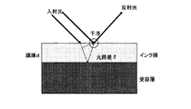
しかしながら、従来の設計方針では、正反射光の色づき現象(以下、単に「干渉色」ということがある)を防止することができない。干渉色とは、図11に示すように、光路差δに基づく光の位相ずれにより、特定の波長が強めあったり弱めあったりする結果、反射光に色がつく現象である。
このような現象は、印字物の表面が十分に平滑である場合にのみ起きるため、表面形状が平滑ではなく荒れるような特性のインクを使用すれば問題にならないことが知られている。しかし一方で、このような特性のインクを用いた場合には印刷物全体の光沢の鮮鋭性が低下してしまう。
However, the conventional design policy cannot prevent the coloring phenomenon of the regular reflected light (hereinafter, simply referred to as “interference color”). As shown in FIG. 11, the interference color is a phenomenon in which reflected light is colored as a result of a specific wavelength becoming stronger or weaker due to a phase shift of light based on an optical path difference δ.
Since such a phenomenon occurs only when the surface of the printed matter is sufficiently smooth, it is known that there will be no problem if ink having such characteristics that the surface shape is not smooth but rough. On the other hand, however, when ink having such characteristics is used, the sharpness of the gloss of the entire printed matter is lowered.
本発明は、光沢の鮮鋭性を維持したまま干渉色を低減することができる画像形成装置及び画像形成方法等を提供することを目的とする。 An object of the present invention is to provide an image forming apparatus, an image forming method, and the like that can reduce interference colors while maintaining the sharpness of gloss.
本発明に係る画像形成装置は、色材として顔料を含有する複数の色材を用いて、記録媒体の搬送方向に並ぶ複数の記録素子で構成される記録素子列を前記色材の数分備える記録ヘッドを、前記記録媒体上の同一画像領域において前記搬送方向とは交差する方向に複数回記録走査させることにより画像を形成する画像形成装置であって、画像を表す画像データを入力する入力手段と、前記画像データを、前記画像を複数のドットによって表したドットデータに変換する変換手段と、前記ドットデータに対し、前記複数回の記録走査の各々に対する前記記録素子を割り当てる割り当て手段と、前記画像データに対し、階調を低下させながら量子化する量子化手段と、を有し、前記割り当て手段は、前記同一画像領域において、前記ドットが所定の大きさのクラスタを形成するように集中させ、かつ、少なくとも1つの前記ドットが重なるように割り当て、前記量子化手段は、量子化後の信号を空間的に集中させ、前記割り当て手段により重なるドットの情報に基づき、量子化誤差を補正することを特徴とする。 The image forming apparatus according to the present invention includes a plurality of recording elements arranged in the transport direction of the recording medium, using a plurality of recording elements arranged in the conveyance direction of the recording medium, by the number of the coloring materials. An image forming apparatus for forming an image by causing a recording head to perform recording scanning a plurality of times in a direction intersecting the conveyance direction in the same image area on the recording medium, and for inputting image data representing the image When, the image data, a conversion means for converting the image into dot data expressed by a plurality of dots, the relative dot data, and assignment means for assigning the recording element for each of said plurality of printing scans, the the image data comprises quantizing means for quantizing while reducing the tone, wherein the assigning means, in the same image region, the dot is given Concentrated to to form a can of the cluster, and assigned to at least one of the dots overlap, the quantization means, spatially concentrate the signal after quantization, the dots overlap by said assigning means The quantization error is corrected based on the information .
本発明によれば、光沢の鮮鋭性を維持しながら、干渉色を低減することができる。 According to the present invention, it is possible to reduce interference colors while maintaining the sharpness of gloss.
以下、本発明の実施形態について添付の図面を参照して具体的に説明する。 Hereinafter, embodiments of the present invention will be specifically described with reference to the accompanying drawings.
(第1の実施形態)
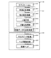
先ず、本発明の第1の実施形態について説明する。図1は、本発明の第1の実施形態に係る画像形成装置を備えた画像形成システムの構成を示すブロック図である。
この画像形成システムには、インクジェットプリンタ等のプリンタ(画像形成装置)104、プリンタ104に画像データを供給するパーソナルコンピュータ(PC)100、及びPC100が出力する映像データを表示するモニタ106が含まれている。
(First embodiment)
First, a first embodiment of the present invention will be described. FIG. 1 is a block diagram illustrating a configuration of an image forming system including an image forming apparatus according to a first embodiment of the present invention.
The image forming system includes a printer (image forming apparatus) 104 such as an ink jet printer, a personal computer (PC) 100 that supplies image data to the
PC100には、ハードウェアとして、ハードディスク(HD)107、中央処理装置(CPU)108、ランダムアクセスメモリ(RAM)109及びリードオンリーメモリ(ROM)110等が設けられている。そして、例えばHD107又はROM110に、オペレーティングシステム(OS)102、アプリケーションソフトウェア101、プリンタドライバ103及びモニタドライバ105が格納されている。
アプリケーションソフトウェア101は、ワードプロセッサ(ワープロ)、表計算及び/又はインターネットブラウザ等に関する処理を行う。モニタドライバ105は、モニタ106に表示する画像データの作成等の処理を実行する。プリンタドライバ103は、アプリケーションソフトウェア101からOS102へ発行される各種描画命令(イメージ描画命令、テキスト描画命令、グラフィック描画命令等)を描画処理して、プリンタ104で用いる2値の画像データを生成する。詳細は後述するが、プリンタドライバ103は、所定の画像処理を実行することにより、プリンタ104で用いる複数のインク色夫々の2値の画像データを生成する。
CPU108は、HD107又はROM110に格納されているソフトウェアに従ってその処理を実行し、その処理実行の際にRAM109をワークエリアとして用いる。このように、PC100は、オペレーティングシステム(OS)102によって、アプリケーションソフトウェア101、プリンタドライバ103及びモニタドライバ105の各ソフトウェアを動作させ、ホストコンピュータとして機能する。
The PC 100 is provided with a hard disk (HD) 107, a central processing unit (CPU) 108, a random access memory (RAM) 109, a read only memory (ROM) 110, and the like as hardware. For example, an operating system (OS) 102,
The
The
プリンタ104は、例えば、インクを吐出する記録ヘッドを記録媒体に対して走査し、その間にインクを吐出して記録を行う所謂シリアル方式のプリンタである。C(シアン)、M(マゼンダ)、Y(イエロー)、K(ブラック)夫々のインクに対応して各色の記録ヘッドが設けられており、各記録ヘッドがキャリッジに装着されている。キャリッジの記録用紙等の記録媒体に対する走査に伴って、各記録ヘッドも走査を行う。各記録ヘッドの吐出口の配列密度は、例えば1200dpiであり、夫々の吐出口から3ピコリットルのインク滴が吐出される。また、各記録ヘッドの吐出口の数は、例えば768個である。
また、プリンタ104にはメモリが設けられており、このメモリに後述の走査及びインク色毎に定められたマスクパターンが格納されている。そして、プリンタ104は、このマスクパターンを用いて2値の分割画像データを生成しながら、又は生成した上で、画像形成を行う。従って、プリンタ104は、マルチパス記録を実行することが可能である。
The
The
図2は、プリンタ104による画像形成に関するPC100及びプリンタ104の主な機能構成を示す機能ブロック図である。
FIG. 2 is a functional block diagram showing main functional configurations of the PC 100 and the
PC100のアプリケーションソフトウェア101は、ユーザがプリンタ104で画像形成する画像データを作成することができるように構成されている。そして、画像形成が行われる際には、アプリケーションソフトウェア101で作成された画像データがプリンタドライバ103に渡される。
The
プリンタドライバ103は、色補正処理部J001、色分解処理部J002、γ補正部J003、2値化処理部J004及び印刷データ作成処理部J005として機能する。
色補正処理部J001は、アプリケーションソフトウェア101で作成された画像データを表示するモニタ106の色域をプリンタ104の色域に変換する色域変換を行う。具体的には、R(レッド)、G(グリーン)、B(ブルー)夫々が8ビットで表現された画像データを3次元LUT(ルックアップテーブル)により、プリンタ104の色域内の8ビットデータR、G、Bに変換する。
色分解処理部J002は、色補正処理部J001により変換された色域を再現する色をインク色に分解する。具体的には、色補正処理部J001によって得られた8ビットデータR、G、Bが表す色を再現するためのインクの組み合わせに対応した8ビットデータC、M、Y、Kを求める処理を行う。
γ補正部J003は、色分解処理部J002によって得られたC、M、Y、Kのデータ夫々について、γ補正を行う。具体的には、色分解処理部J002によって8ビットデータC、M、Y、K夫々がプリンタ104の階調特性に線形に対応付けられるような変換を行う。
2値化処理部J004は、γ補正がなされた8ビットデータC、M、Y、K夫々を1ビットC、M、Y、Kに変換する階調変換処理を行う。つまり、量子化部として、階調を低下させながら量子化する。また、この際に、量子化後の信号を空間的に集中させる。
印刷データ作成処理部J005は、2値化された1ビットC、M、Y、Kを内容とする2値の画像データに印刷制御データ等を付して印刷データを作成する。ここで、2値の画像データは、ドットの記録を示すドット記録データ、及びドットの非記録を表すドット非記録データを含む。なお、印刷制御データには、記録媒体情報、記録品位情報及び給紙方法等の制御情報が含まれる。
そして、色補正処理部J001、色分解処理部J002、γ補正部J003、2値化処理部J004及び印刷データ作成処理部J005による一連の処理を経て作成された印刷データが、プリンタ104へ供給される。
The
The color correction processing unit J001 performs color gamut conversion that converts the color gamut of the
The color separation processing unit J002 separates the color that reproduces the color gamut converted by the color correction processing unit J001 into ink colors. Specifically, a process for obtaining 8-bit data C, M, Y, K corresponding to a combination of inks for reproducing the colors represented by the 8-bit data R, G, B obtained by the color correction processing unit J001. Do.
The γ correction unit J003 performs γ correction on each of the C, M, Y, and K data obtained by the color separation processing unit J002. Specifically, the color separation processing unit J002 performs conversion such that each of the 8-bit data C, M, Y, and K is linearly associated with the gradation characteristics of the
The binarization processing unit J004 performs gradation conversion processing for converting 8-bit data C, M, Y, and K that have been subjected to γ correction into 1-bit C, M, Y, and K, respectively. That is, the quantization unit performs quantization while reducing the gradation. At this time, the quantized signal is spatially concentrated.
The print data creation processing unit J005 creates print data by attaching print control data or the like to binary image data containing 1-bit C, M, Y, and K that are binarized. Here, the binary image data includes dot recording data indicating dot recording and dot non-recording data indicating dot non-recording. The print control data includes control information such as recording medium information, recording quality information, and paper feeding method.
Print data created through a series of processing by the color correction processing unit J001, color separation processing unit J002, γ correction unit J003, binarization processing unit J004, and print data creation processing unit J005 is supplied to the
プリンタ104は、入力された印刷データに含まれる2値の画像データに対し、マスクデータ変換処理を行うマスクデータ変換処理部J006として機能する。マスクデータ変換処理部J006は、予めプリンタ104の所定のメモリに格納されているマスクパターンを用いて、入力された2値の画像データに対し論理積を計算する。この結果、マルチパス記録における夫々の走査で用いられる2値の分割画像データ(ドットデータ)が生成され、また、実際にインクが吐出されるタイミングが決定される。なお、2値の分割画像データには、上述のように、ドット記録データ及びドット非記録データが含まれる。
The
また、プリンタ104には、上述の4色のインクを吐出する記録ヘッドとして、色毎に記録ヘッドJ008が設けられている。更に、プリンタ104にはヘッド駆動回路J007が含まれており、ヘッド駆動回路J007は、記録ヘッドJ008に2値の分割画像データに基づき所定のタイミングでインクを吐出させる。C、M、Y、K各インクを記録するための記録ヘッド及びインクタンクが搭載されたヘッドによる1回の主走査を終了すると、記録媒体が副走査方向(主走査方向と垂直方向)に所定量だけ搬送される。このような主走査及び副走査を交互に繰り返すことにより、マルチパス記録(画像形成)により画像が順次形成されていく。
Further, the
次に、第1の実施形態で用いられるマスクパターン(パスマスク)について説明する。第1の実施形態では、量子化後の信号を空間的に集中させる、つまり「ドットをクラスタ化」させ、かつ「ドットonドット」にするマスクパターンが用いられる。このマスクパターンは、上述のように、所定のメモリに予め格納されており、マスクデータ変換処理部J006がマスクデータ変換処理を行う際にこのマスクパターンを用いる。
マスクデータ変換処理部J006は、変換部及び割り当て部として、2値画像データB(x,y)に、マルチパス記録のマスクパターンM(i,j)を適用することにより、各ドットを記録する記録素子及び記録順序を制御する。ここで、(x,y)は画像の画素位置を示す座標であり、2値画像データB(x,y)は画素位置(x,y)における濃度値を示す。即ち、2値のインクジェットプリンタにおいては、B(x,y)=1ならば黒ドット(ドットON)、B(x,y)=0ならば白ドット(ドットOFF)であることを意味する。
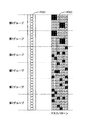
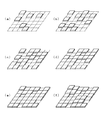
図3は、マスクパターンの一例を示す模式図である。この例では、マルチパス記録の走査回数が6回とされている。また、記録ヘッドP001のノズル数は36個であり、ノズルは第1から第6までのグループに分割され、各グループには夫々6つのノズルが含まれている。また、各グループは、1主走査の画像形成に対応している。記録ヘッドの構造は、C、M、Y、K間で共通であり、記録ヘッドP001は、そのうちの1つに該当する。また、2値画像データB(x,y)の画像サイズは6×6である。そして、各グループのノズル列に夫々対応してマスクパターンP003が設定されている。夫々のマスクパターンP003では、記録許容画素が黒塗りで1、非記録許容画素が白塗りで0として示されている。
本実施形態では、図3に示すように、第1〜第4グループには、ドットの分散性の高いマスクパターンが設定され、第5〜第6グループには、2×2の領域に集中したマスクパターンが設定されている。従って、第4パス目までは分散性が高くなるようにドットが記録され、第5パス目では2×2の領域に集中してドットが記録され、第6パス目では第5パス目と同じ2×2の領域に集中してドットが重ねられる。
Next, a mask pattern (pass mask) used in the first embodiment will be described. In the first embodiment, a mask pattern is used in which the quantized signals are spatially concentrated, that is, “dots are clustered” and “dots on dots” are used. As described above, this mask pattern is stored in advance in a predetermined memory, and this mask pattern is used when the mask data conversion processing unit J006 performs the mask data conversion process.
The mask data conversion processing unit J006 records each dot by applying the multi-pass printing mask pattern M (i, j) to the binary image data B (x, y) as the conversion unit and the allocation unit. Control recording elements and recording order. Here, (x, y) is a coordinate indicating the pixel position of the image, and the binary image data B (x, y) indicates a density value at the pixel position (x, y). That is, in a binary ink jet printer, B (x, y) = 1 means black dots (dots ON), and B (x, y) = 0 means white dots (dots OFF).
FIG. 3 is a schematic diagram showing an example of a mask pattern. In this example, the number of scans for multipass printing is six. The number of nozzles of the recording head P001 is 36, and the nozzles are divided into first to sixth groups, and each group includes six nozzles. Each group corresponds to image formation of one main scan. The structure of the recording head is common among C, M, Y, and K, and the recording head P001 corresponds to one of them. The image size of the binary image data B (x, y) is 6 × 6. A mask pattern P003 is set corresponding to each group of nozzle rows. In each mask pattern P003, the print permitting pixel is shown as 1 in black, and the non-printing allowance pixel is shown as 0 in white.
In this embodiment, as shown in FIG. 3, mask patterns with high dot dispersion are set in the first to fourth groups, and concentrated in a 2 × 2 region in the fifth to sixth groups. A mask pattern is set. Therefore, the dots are recorded so that the dispersibility is high until the fourth pass, the dots are recorded concentrated on the 2 × 2 area in the fifth pass, and the same as the fifth pass in the sixth pass. Dots are superimposed on the 2 × 2 area.
ここで、本実施形態におけるマスクパターンP003と従来のマスクパターンとの相違について説明する。
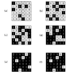
図4(a)は、従来のマスクパターンの一例を示し、図4(b)は、本実施形態におけるマスクパターンP003を示す。
いずれのマスクパターンも、縦方向に6つの領域に等分割され、各領域の縦方向画素数はインクジェットプリンタのヘッドのノズル数に等しい。そして、各領域の黒ドットにより、各パスの記録における記録素子の割り当てが決定される。即ち、各パスの記録において、マスクパターンの対応する領域(1パス目であれば、下部1/6の領域)と、2値画像B(x,y)との論理積をとり、出力するドットが決定される。
但し、図4(a)と図4(b)とを比較すると明確なように、従来のマスクパターンでは、各グループ間でマスクパターンがほぼ等しいのに対し、マスクパターンP003では、第5パス、第6パスに相当する第5及び第6グループにおいて、ドットが所定の大きさのクラスタになるように集中している。また、マスクパターンP003では、第5グループ及び第6グループの間で、マスクパターンが同一となっている。但し、第5グループ及び第6グループの間でマスクパターンが完全に同一でなくてもよく、一定の割合で同一位置に記録されるようになっていればよい。また、ドットにより所定の大きさのクラスタを形成し、かつ、パターンを同一にするグループは、任意のグループであってもよい。但し、本願発明者らの実験によると、後半に記録されるパス(6パス記録の場合は第5、第6パス目)に相当するグループで同一になっている場合に最も効果が大きいことがわかっている。
Here, the difference between the mask pattern P003 in the present embodiment and the conventional mask pattern will be described.
FIG. 4A shows an example of a conventional mask pattern, and FIG. 4B shows a mask pattern P003 in the present embodiment.
Each mask pattern is equally divided into six regions in the vertical direction, and the number of vertical pixels in each region is equal to the number of nozzles of the head of the inkjet printer. Then, the allocation of printing elements in printing in each pass is determined by the black dots in each area. That is, in printing each pass, a dot that is output by taking the logical product of the corresponding region of the mask pattern (the lower 1/6 region if it is the first pass) and the binary image B (x, y). Is determined.
However, as is clear when comparing FIG. 4A and FIG. 4B, in the conventional mask pattern, the mask pattern is almost equal between the groups, whereas in the mask pattern P003, the fifth pass, In the fifth and sixth groups corresponding to the sixth pass, the dots are concentrated so as to form clusters of a predetermined size. In the mask pattern P003, the mask pattern is the same between the fifth group and the sixth group. However, the mask patterns may not be completely the same between the fifth group and the sixth group, and it is only necessary that they are recorded at the same position at a certain rate. In addition, a group in which a cluster having a predetermined size is formed by dots and the pattern is the same may be an arbitrary group. However, according to the experiments by the inventors of the present application, it is most effective when the groups corresponding to the passes recorded in the second half (the fifth and sixth passes in the case of 6-pass printing) are the same. know.
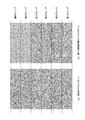
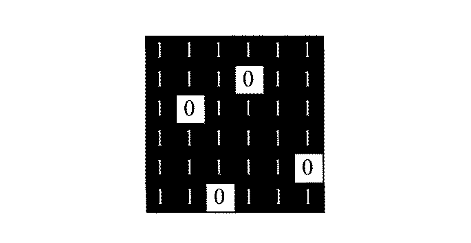
次に、マスクパターンP003を用いたマスクデータ変換処理について説明する。図5は、サイズが6×6の2値画像データB(x,y)の一例を示す模式図である。
マスクデータ変換処理では、マスクパターンP003の各グループのマスクパターンM(i,j)と2値画像データB(x,y)との論理積が演算され、その結果が累積されていく。つまり、先ず、第1パス目で、第1グループのマスクパターンM(i,j)と2値画像データB(x,y)との論理積が演算され、図6(a)に示すドットが配置される。次いで、第2パス目で、第2グループのマスクパターンM(i,j)と2値画像データB(x,y)との論理積が演算され、この結果が図6(a)に示すドットに加算されて図6(b)に示すドットが配置される。このような処理が繰り返されて、順次、図6(c)、図6(d)、図6(e)、図6(f)に示すドットが配置されていく。なお、図6では、画素にドットが1個配置される場合は1、ドットが2個配置される場合は2、3個配置される場合は3、と示している。このように、各グループにおける、図5に示す2値画像データB(x,y)とマスクパターンM(i,j)との論理積を、逐次加算することにより、図6(f)に示す画像が形成される。
Next, a mask data conversion process using the mask pattern P003 will be described. FIG. 5 is a schematic diagram illustrating an example of binary image data B (x, y) having a size of 6 × 6.
In the mask data conversion process, the logical product of the mask pattern M (i, j) of each group of the mask pattern P003 and the binary image data B (x, y) is calculated, and the results are accumulated. That is, first, in the first pass, the logical product of the mask pattern M (i, j) of the first group and the binary image data B (x, y) is calculated, and the dots shown in FIG. Be placed. Next, in the second pass, the logical product of the second group mask pattern M (i, j) and the binary image data B (x, y) is calculated, and the result is the dot shown in FIG. To the dots shown in FIG. 6B. Such processing is repeated, and the dots shown in FIG. 6C, FIG. 6D, FIG. 6E, and FIG. 6F are sequentially arranged. In FIG. 6, 1 is shown when one dot is arranged in a pixel, 2 is shown when two dots are arranged, and 3 is shown when three dots are arranged. In this way, by sequentially adding the logical product of the binary image data B (x, y) and the mask pattern M (i, j) shown in FIG. 5 in each group, the result shown in FIG. An image is formed.
図7は、上述のマルチパス記録の結果を示す模式図である。図7には、図6(f)に示すドットの配置を立体的に示している。図7に示すように、このような第1の実施形態によれば、印刷物の表面形状が荒れるようなインクを用いずとも、印刷物の表面に微小な凹凸が形成される。このため、光路差にばらつきを生じさせて、干渉色を抑制することができる。なお、実際には、図7のようにドットを直方体にすることは困難であり、その必要もない。ドット形状が円柱であっても第1の実施形態の効果が失われることはなく、印字ドットの形状は限定されない。 FIG. 7 is a schematic diagram showing a result of the above-described multipass recording. FIG. 7 shows a three-dimensional arrangement of the dots shown in FIG. As shown in FIG. 7, according to the first embodiment, minute irregularities are formed on the surface of the printed material without using ink that causes the surface shape of the printed material to be rough. For this reason, variation in the optical path difference can be caused and interference colors can be suppressed. In practice, it is difficult to form dots in a rectangular parallelepiped as shown in FIG. Even if the dot shape is a cylinder, the effect of the first embodiment is not lost, and the shape of the print dot is not limited.
ここで、マスクパターンP003(パスマスク)を設計する方法について説明する。ここでは、斥力ポテンシャルの概念を用いたマスクパターン設計技術を基とし、上述のようなマスクパターンM(i,j)を作成する方法について説明する。なお、斥力ポテンシャルの概念を用いたマスクパターン設計技術は公知であり、例えば、特開2002−144552号公報及び特開2006−44258号公報に記載されている。
先ず、クラスタサイズ及びどのパスを重ねるかを決定する。本実施形態では、クラスタサイズを2×2とし、第5パス目と第6パス目とを重ねることとする。
次いで、斥力ポテンシャルを用い、第5パス目のマスクパターンのみを設計する。この際に、生成されるドットは2×2のクラスタになるように制約を設ける。なお、制約の設け方については、例えば2×2領域の画素を1画素とみなして設計すればよい。
その後、第6パス目のマスクパターンとして、第5パス目と同一のものを設計する。但し、上述のように、完全に同一でなくてもよく、一定の割合で同一位置に画像形成されるようなマスクパターンであればよい。
続いて、第1パス目から第4パス目までのマスクパターンを、例えば特開2002−144552号公報及び特開2006−44258号公報に記載された斥力ポテンシャルの概念を用いたマスクパターン設計技術に基づいて作成する。この際には、既に作成してある第5パス目及び第6パス目からの斥力ポテンシャルを考慮して設計することが好ましい。
このような方法により、第1の実施形態における各グループのマスクパターンM(i,j)を設計することができる。なお、ここでは基となるマスクパターン設計技術として斥力ポテンシャルを用いた技術を挙げているが、所定のグループにおいてドットをクラスタ化して重ねることが可能であれば、基となるマスクパターン設計技術は特定のものに限定されない。
Here, a method for designing the mask pattern P003 (pass mask) will be described. Here, a method for creating the above-described mask pattern M (i, j) based on the mask pattern design technique using the concept of repulsive potential will be described. Note that a mask pattern design technique using the concept of repulsive potential is known, and is described in, for example, Japanese Patent Application Laid-Open Nos. 2002-144552 and 2006-44258.
First, the cluster size and which path is to be overlapped are determined. In the present embodiment, the cluster size is 2 × 2, and the fifth pass and the sixth pass are overlapped.
Next, only the mask pattern of the fifth pass is designed using the repulsive potential. At this time, a restriction is provided so that the generated dots are 2 × 2 clusters. Note that the method of providing the constraints may be designed, for example, by regarding a pixel in a 2 × 2 region as one pixel.
Thereafter, the same mask pattern as the fifth pass is designed as the sixth pass mask pattern. However, as described above, it is not necessary to be completely the same, and any mask pattern may be used as long as an image is formed at the same position at a constant rate.
Subsequently, the mask pattern from the first pass to the fourth pass is applied to a mask pattern design technique using the concept of repulsive potential described in, for example, Japanese Patent Application Laid-Open Nos. 2002-144552 and 2006-44258. Create based on. In this case, it is preferable to design in consideration of the repulsive potential from the fifth pass and the sixth pass already created.
By such a method, the mask pattern M (i, j) of each group in the first embodiment can be designed. Here, the technology using repulsive potential is cited as the base mask pattern design technology, but if the dots can be clustered and stacked in a given group, the base mask pattern design technology is specified. It is not limited to those.
なお、本実施形態では4色のインク全てのパスマスクについて上記で生成されたパスマスクを適用したが、インクの種類に応じて、インク毎に選択的に適用することがより好ましい。特に、例えばイエローのインク、淡インク(例えば淡シアン、淡マゼンタ、及び淡グレイ等)、並びにクリアインク等のような低濃度インクに選択的に適用することが好ましい。なぜならば、低濃度インクは高濃度インクに比較して干渉色が発生しやすいためである。更に、ドットのクラスタ化による粒状感の劣化の程度が少ないことも理由である。
また、上記で生成されたパスマスクの適用は、出力モードに応じて選択的に適用してもよい。例えば、ユーザが出力モードとして干渉色の低減を優先させる干渉色低減優先モードを選択した場合に適用することができる。また、出力する画像の種類(例えば写真及び文書等)、並びに用紙の種類等に応じて自動的に切り替える構成としてもよい。
なお、本実施形態では4色のインクを用いた例を用いて説明したが、4色以上のインクを用いてもよく、3色以下のインクを用いてもよい。即ち、インク数は4色のインクに限定されない。
なお、本実施形態ではカラー印刷の例を用いて説明したが、モノクロ印刷に適用しても良い。その場合には、特に淡グレイインクに選択的に適用することが好ましい。
なお、本実施形態ではマルチパス記録の走査回数を6回としたが、その回数は限定されない。また、画像データは2値でなくてもよく、その階調数は限定されない。
なお、マスクパターンP003が所定のメモリに予め格納されて、PC100がマスク生成のデータ処理装置として機能してもよい。この場合、PC100が上述のマスクパターンP003(パスマスク)の生成を行い、この結果得られたマスクパターンP003がプリンタ104の所定のメモリに格納される。
In the present embodiment, the pass mask generated above is applied to the pass masks for all the four color inks. However, it is more preferable to apply the pass mask selectively for each ink according to the type of ink. In particular, it is preferable to selectively apply to low density inks such as yellow ink, light ink (for example, light cyan, light magenta, and light gray), and clear ink. This is because low density ink tends to generate interference colors compared to high density ink. Another reason is that the degree of graininess deterioration due to dot clustering is small.
The application of the path mask generated above may be selectively applied according to the output mode. For example, the present invention can be applied when the user selects an interference color reduction priority mode that prioritizes reduction of interference colors as an output mode. Further, a configuration may be adopted in which switching is automatically performed according to the type of image to be output (for example, a photograph and a document) and the type of paper.
In this embodiment, an example using four colors of ink has been described. However, four or more colors of ink may be used, or three or less colors of ink may be used. That is, the number of inks is not limited to four color inks.
In the present embodiment, the example of color printing has been described, but it may be applied to monochrome printing. In that case, it is particularly preferable to selectively apply to light gray ink.
In the present embodiment, the number of scans for multipass printing is six, but the number of scans is not limited. The image data may not be binary, and the number of gradations is not limited.
Note that the mask pattern P003 may be stored in advance in a predetermined memory, and the
(第2の実施形態)
次に、本発明の第2の実施形態について説明する。第1の実施形態では、マスクパターンM(i,j)において同一位置にドットを形成しているため、画像全体の濃度保存性が問題となる虞もある。そこで、第2の実施形態では、階調変換の際にマスクパターンM(i,j)に応じた補正をかけることにより、このような問題の発生を予め抑制する。従って、2値化処理部J004の動作が第1の実施形態と相違している。他の構成及び動作は第1の実施形態と同様である。
(Second Embodiment)
Next, a second embodiment of the present invention will be described. In the first embodiment, since dots are formed at the same position in the mask pattern M (i, j), there is a possibility that the density conservation of the entire image may become a problem. Therefore, in the second embodiment, the occurrence of such a problem is suppressed in advance by applying correction according to the mask pattern M (i, j) at the time of gradation conversion. Therefore, the operation of the binarization processing unit J004 is different from that of the first embodiment. Other configurations and operations are the same as those in the first embodiment.
本実施形態でも、2値化処理部J004が2値画像データB(x,y)を生成する。上述のように、2値画像データB(x,y)は画素位置(x,y)における濃度値を示す。そして、本実施形態では、第1の実施形態と同様にして作成され、プリンタ104の所定のメモリに格納されるマスクパターンM(i,j)を参照して、階調変換に補正をかける。ここでは、階調変換方法として誤差拡散法を用いた場合の量子化誤差の補正処理について説明する。
一般的な2値の誤差拡散法では、数1及び数2により2値出力画像B(x,y)を決定する。
Also in this embodiment, the binarization processing unit J004 generates binary image data B (x, y). As described above, the binary image data B (x, y) indicates the density value at the pixel position (x, y). In this embodiment, gradation conversion is corrected with reference to a mask pattern M (i, j) created in the same manner as in the first embodiment and stored in a predetermined memory of the
In a general binary error diffusion method, a binary output image B (x, y) is determined by
ここで、I(x,y)は階調変換前の入力画像の濃度値であり、T(x,y)は任意の閾値である。また、D(x,y)は拡散誤差積算であり、数2により定義される誤差E(x,y)が近傍画素に拡散された値である。なお、誤差拡散の割合は、図8に示すような誤差拡散係数によって決定される。図8に示す拡散係数を適用した場合には、任意の画素は、近傍の4画素から拡散された誤差を全て受け取ることになる(但し、画像端は例外である)。
これに対し、本実施形態では、数1の代わりに数3を用いる。
Here, I (x, y) is a density value of the input image before gradation conversion, and T (x, y) is an arbitrary threshold value. D (x, y) is a diffusion error integration, and is a value obtained by diffusing the error E (x, y) defined by
On the other hand, in this embodiment,
ここで、cは、マスクパターンM(i,j)において、画素位置(x,y)に対応する各パスのドットがONになっている数である。なお、B(x,y)≧2の場合も、B(x,y)=1の場合と同様、単に黒ドット(ドットON)であることを意味する。但し、B(x,y)≧2である場合、数2により算出される誤差E(x,y)の値には影響が及ぶ。
上記の数3を用いることにより、画像全体の濃度を保存したまま階調変換することができる。例えば、マスクパターンM(i,j)によって必ずOFFになってしまうドットがあったとしても、階調変換後の値を0にし、誤差を周囲に拡散することができる。
Here, c is the number of dots in each pass corresponding to the pixel position (x, y) in the mask pattern M (i, j). Note that even when B (x, y) ≧ 2, as in the case of B (x, y) = 1, it simply means a black dot (dot ON). However, when B (x, y) ≧ 2, the value of the error E (x, y) calculated by
By using
このように、第2の実施形態では、「ハーフトーン」でマスクパターンの「ドットonドット」を考慮して濃度保存し、2値画像データB(x,y)の生成の際に、マスクパターンM(i,j)に応じた補正をかけている。このため、第1の実施形態と同様の効果が得られるだけでなく、画像全体の濃度保存性の問題の発生を予め抑制することができる。 As described above, in the second embodiment, the density is stored in consideration of “dot on dot” of the mask pattern in “halftone”, and the mask pattern is generated when the binary image data B (x, y) is generated. Correction according to M (i, j) is applied. For this reason, not only the effect similar to 1st Embodiment is acquired but generation | occurrence | production of the problem of the density preservation property of the whole image can be suppressed previously.
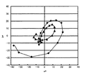
ここで、第2の実施形態により干渉色が低減されたことを示す実験結果について説明する。第1の実験では、ある階調パッチを印刷し、正反射光の分光特性をLab*値に変換した結果を得た。これをプロットしたものを図9に示す。図9中の破線及び◆で示す結果が、従来のマスクパターンを用いた場合のものであり、実線及び▲で示す結果が、第2の実施形態におけるマスクパターンM(i,j)を用いた場合のものである。
図9に示すように、第2の実施形態におけるマスクパターンM(i,j)を用いた場合には、従来のマスクパターンを用いた場合と比較して正反射光のa*b*値が0に近づいた。このことは、干渉色が抑制されていることを示している。このような効果は、第1の実施形態と同様に、印刷物の表面形状に微小な凹凸が形成されたために、光路差にばらつきが生じ、干渉の効果が弱まったためである。
Here, an experimental result indicating that the interference color is reduced by the second embodiment will be described. In the first experiment, a tone patch was printed, and the spectral characteristics of specularly reflected light were converted into Lab * values. A plot of this is shown in FIG. The results indicated by broken lines and ◆ in FIG. 9 are obtained when the conventional mask pattern is used, and the results indicated by solid lines and ▲ are obtained by using the mask pattern M (i, j) in the second embodiment. Is the case.
As shown in FIG. 9, when the mask pattern M (i, j) in the second embodiment is used, the a * b * value of the specularly reflected light is higher than when the conventional mask pattern is used. I approached zero. This indicates that the interference color is suppressed. Such an effect is because, as in the first embodiment, since minute irregularities are formed on the surface shape of the printed matter, the optical path difference varies and the interference effect is weakened.
第2の実験では、同階調パッチの光沢鮮鋭性を評価した。この結果を図10に示す。図9と同様に、図10中の破線及び◆で示す結果が、従来のマスクパターンを用いた場合のものであり、実線及び▲で示す結果が、第2の実施形態におけるマスクパターンM(i,j)を用いた場合のものである。
図10に示すように、第2の実施形態におけるマスクパターンM(i,j)を用いた場合の光沢鮮鋭性は従来のものと同等であり、光沢鮮鋭性の低下を回避できたといえる。これは、表面形状の法線ベクトルの分布がほとんど変化していないためである。なお、本評価に用いた光沢鮮鋭性評価値においては2.0程度の差は主観的に差異が判別できない程度である。
In the second experiment, the gloss sharpness of the same gradation patch was evaluated. The result is shown in FIG. As in FIG. 9, the results indicated by broken lines and ◆ in FIG. 10 are obtained when a conventional mask pattern is used, and the results indicated by solid lines and ▲ indicate the mask pattern M (i in the second embodiment. , J).
As shown in FIG. 10, the gloss sharpness when using the mask pattern M (i, j) in the second embodiment is equivalent to the conventional one, and it can be said that the reduction of the gloss sharpness can be avoided. This is because the distribution of the normal vector of the surface shape has hardly changed. In the gloss sharpness evaluation value used in this evaluation, a difference of about 2.0 is such that the difference cannot be determined subjectively.
なお、同一位置にドットを複数回記録した際の濃度増加は、一般に非線形であるため、数3に、更に非線形の補正をかけることがより好ましい。
また、第2の実施形態では、階調変換方法として2値の誤差拡散法が採用されているが、基本となる階調変換方法はこれに限定されない。
Note that the increase in density when dots are recorded a plurality of times at the same position is generally non-linear. Therefore, it is more preferable to further apply non-linear correction to equation (3).
In the second embodiment, the binary error diffusion method is adopted as the gradation conversion method, but the basic gradation conversion method is not limited to this.
(第3の実施形態)
次に、本発明の第3の実施形態について説明する。第1の実施形態では、パスマスクによって集中させられるドットの集中度合いであるドット集中性に着目した処理を行っているが、ハーフトーンについてもドット集中性を制御することが好適である。また、ハーフトーンのドット集中性については、入力画像の階調に応じて選択的に変更することが好適である。その理由は、図9中の破線及び実線で示す結果から読み取ることができる。原点からの距離で表される干渉色の強さは、始めに原点から大きく離れた(図9中の中央から右上へかけての変化)後、いったん近づき(図9中の右下領域)、再び大きく離れている(図9中の左下領域)。
このように、干渉色の強さは階調によって変動するため、干渉色低減処理についても、階調に応じて選択的に切り替えることが望ましい。例えば、正反射光のa*b*の原点からの距離に応じて、干渉色低減処理の強さを変えることが好適である。ここで、干渉色低減処理の強さを変更する方法としては、ハーフトーンにおけるドットの集中度を制御する方法を用いることができる。
そこで以下では、階調に応じた選択的なドット集中型ハーフトーンを用いる例について説明する。第1の実施形態と同様である処理については説明を省略する。
本実施形態では、図2における2値化処理部J004は、5値データP(x,y)を生成した後、5値データP(x,y)を元に2値画像データB(x,y)を生成する。5値データP(x,y)の生成には、公知の手法である5値の誤差拡散法を用いる。また、5値データP(x,y)から2値データB(x,y)を生成する際には、濃度パターン法を用いる。ここで、濃度パターン法とは、特定の階調に対して定められたドットパターンを割り当てる方法である。本実施形態では、以下に示すように、画素位置(x,y)に応じて割り当てるドットパターンを変更する例について説明するが、この例に限定されるものではない。
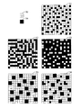
図12はドットパターンの一例を示す図であり、ドットパターン50は出力階調の階調レベルが0である場合に対応するドットパターンの例である。以下同様に、ドットパターン51は出力階調1/4に対応し、ドットパターン52は出力階調2/4に対応し、ドットパターン53は出力階調3/4に対応し、ドットパターン54は出力階調1に対応する。
図12に示された各マス目は出力ドット領域に対応し、黒のマス目は当該ドットを記録することを、白のマス目は当該ドットを記録しないことを表す。ここで、2値化処理部J004は、5値データP(x,y)に応じて、ドットパターン50、51、52、53、又は54のいずれかを選択する。更に、ドットパターン51、52、又は53を選択した場合には、画素位置(x,y)を用いて、選択したドットパターンの縦横2画素の領域を選択し、その領域のドットパターンを出力画素とする。例えば、ドットパターン51、52、又は53の横画素数をw、縦画素数をhとしたとき、以下の座標で示される2×2画素を出力ドットパターンとして選択する。
((2x)%w、(2y)%h)
((2x)%w+1、(2y)%h)
((2x)%w、(2y)%h+1)
((2x)%w+1、(2y)%h+1)
ここで、%はモジュロ(剰余)演算を表す。
(Third embodiment)
Next, a third embodiment of the present invention will be described. In the first embodiment, processing focusing on dot concentration, which is the degree of concentration of dots concentrated by the pass mask, is performed, but it is preferable to control dot concentration for halftones. Further, it is preferable that the halftone dot concentration is selectively changed according to the gradation of the input image. The reason can be read from the results shown by the broken line and the solid line in FIG. The intensity of the interference color represented by the distance from the origin is first greatly separated from the origin (change from the center to the upper right in FIG. 9), and then approached (lower right area in FIG. 9). It is greatly separated again (lower left area in FIG. 9).
As described above, since the intensity of the interference color varies depending on the gradation, it is desirable to selectively switch the interference color reduction processing according to the gradation. For example, it is preferable to change the intensity of the interference color reduction process according to the distance from the origin of the a * b * of the regular reflection light. Here, as a method of changing the intensity of the interference color reduction process, a method of controlling the degree of dot concentration in the halftone can be used.
Therefore, in the following, an example using a selective dot concentration type halftone according to the gradation will be described. A description of processing that is the same as in the first embodiment will be omitted.
In this embodiment, the binarization processing unit J004 in FIG. 2 generates the quinary data P (x, y), and then generates the binary image data B (x, y) based on the quinary data P (x, y). y) is generated. For the generation of the quinary data P (x, y), a quinary error diffusion method which is a known method is used. Further, when generating binary data B (x, y) from quinary data P (x, y), a density pattern method is used. Here, the density pattern method is a method of assigning a dot pattern determined for a specific gradation. In the present embodiment, as will be described below, an example in which the dot pattern to be assigned is changed according to the pixel position (x, y) will be described, but the present invention is not limited to this example.
FIG. 12 is a diagram illustrating an example of a dot pattern, and the
Each square shown in FIG. 12 corresponds to an output dot area. A black square represents that the dot is recorded, and a white square represents that the dot is not recorded. Here, the binarization processing unit J004 selects one of the
((2x)% w, (2y)% h)
((2x)% w + 1, (2y)% h)
((2x)% w, (2y)% h + 1)
((2x)% w + 1, (2y)% h + 1)
Here,% represents a modulo (remainder) operation.
本実施形態では、ドットパターン51、52、又は53として、ドット集中するパターンを少なくとも1つ以上選択することにより、階調に応じてドットの集中性を異ならせる。例えば、出力階調1/4に対応するドットパターンとして、ドット集中度の高いドットパターン55を用いる。また、ドット集中性の異なるドットパターンは任意のものを用いてよく、例えばドットパターン56のように一部のドットを出力が素から分離させて分散配置したパターンを用いてもよい。これにより、階調に応じた選択的なドット集中性について制御が可能となる。
In the present embodiment, at least one dot-concentrating pattern is selected as the
なお、ドットパターンの作成手法としては、公知のドット集中型ハーフトーン手法、ディザマトリクス作成手法を用いてもよい。
また、本実施形態では、中間データとして5値データP(x、y)を生成する構成としたが、中間データの階調数は限定されない。
また、本実施形態では、多値誤差拡散法及び濃度パターン法を組み合わせて用いることによりドット集中性を制御する例を説明したが、他の方法を用いてもよい。例えば、特開2007−129446号公報に記載されているようなドット集中型の誤差拡散法を用いてもよく、ディザマトリクス法を用いてもよい。更に、これらに改良を加えた方法を用いてもよい。
なお、上記実施形態において「空間的に集中させる」とは、紙面上の近接位置に複数のドットを集中させることと、複数のドットを重ねて形成することの両方を意味する。特に区別する場合には、前者を「クラスタ化」、後者を「ドット重なり」又は「ドットonドット」と呼称する。
また、本発明は、複数の機器(例えばホストコンピュータ、インターフェイス機器、リーダ、プリンタなど)から構成されるシステムによって実現しても、一つの機器からなる装置(例えば、複写機、ファクシミリ装置等)によって実現してもよい。
また、これらの実施形態では記録媒体(印刷媒体)として用紙が用いられているが、これに限るものではなく、OHP、及びCD−ROMのラベル面が記録媒体として用いられてもよい。
また、これらの実施形態ではプリンタを例に色材としてインクを示したが、これに限るものではなく、複写機を例にトナーを色材としてもよい。
また、本発明の各工程は、ネットワーク又は各種コンピュータ読取り可能な記憶媒体を介して取得したソフトウェア(プログラム)をパーソナルコンピュータ等の処理装置(CPU、プロセッサ)にて実行することでも実現できる。
As a dot pattern creation method, a known dot concentration type halftone method or dither matrix creation method may be used.
In the present embodiment, ternary data P (x, y) is generated as intermediate data, but the number of gradations of the intermediate data is not limited.
In this embodiment, the example in which the dot concentration is controlled by using a combination of the multi-value error diffusion method and the density pattern method has been described. However, other methods may be used. For example, a dot concentration type error diffusion method described in Japanese Patent Application Laid-Open No. 2007-129446 may be used, or a dither matrix method may be used. Furthermore, a method obtained by adding improvements to these may be used.
In the above embodiment, “spatial concentration” means both of concentrating a plurality of dots at close positions on the paper surface and forming a plurality of dots in an overlapping manner. In particular, the former is referred to as “clustering” and the latter as “dot overlap” or “dot on dot”.
Further, the present invention can be realized by a system composed of a plurality of devices (for example, a host computer, an interface device, a reader, a printer, etc.) or by a device (for example, a copier, a facsimile device, etc.) composed of a single device. It may be realized.
In these embodiments, paper is used as a recording medium (printing medium). However, the present invention is not limited to this, and the OHP and CD-ROM label surfaces may be used as the recording medium.
In these embodiments, ink is shown as a color material using a printer as an example. However, the present invention is not limited to this, and toner may be used as a color material using a copying machine as an example.
Each step of the present invention can also be realized by executing software (program) acquired via a network or various computer-readable storage media by a processing device (CPU, processor) such as a personal computer.
101:アプリケーション、103:プリンタドライバ、104:プリンタ、J001:色補正処理部、J002:色分解処理部、J003:γ補正部、J004:2値化処理部、J005:印刷データ作成処理部、J006:マスクデータ変換部、J007:ヘッド駆動回路、J008:記録ヘッド 101: application, 103: printer driver, 104: printer, J001: color correction processing unit, J002: color separation processing unit, J003: γ correction unit, J004: binarization processing unit, J005: print data creation processing unit, J006 : Mask data conversion unit, J007: Head drive circuit, J008: Print head
Claims (3)
画像を表す画像データを入力する入力手段と、
前記画像データを、前記画像を複数のドットによって表したドットデータに変換する変換手段と、
前記ドットデータに対し、前記複数回の記録走査の各々に対する前記記録素子を割り当てる割り当て手段と、
前記画像データに対し、階調を低下させながら量子化する量子化手段と、
を有し、
前記割り当て手段は、前記同一画像領域において、前記ドットが所定の大きさのクラスタを形成するように集中させ、かつ、少なくとも1つの前記ドットが重なるように割り当て、
前記量子化手段は、量子化後の信号を空間的に集中させ、前記割り当て手段により重なるドットの情報に基づき、量子化誤差を補正することを特徴とする画像形成装置。 Using a plurality of color materials containing pigment as a color material, a recording head provided with a number of recording element arrays composed of a plurality of recording elements arranged in the conveyance direction of the recording medium on the recording medium An image forming apparatus for forming an image by performing a recording scan a plurality of times in a direction intersecting the transport direction in the same image area,
Input means for inputting image data representing an image;
Conversion means for converting the image data into dot data representing the image by a plurality of dots;
Assigning means for allocating the recording elements for each of the plurality of recording scans to the dot data;
Quantization means for quantizing the image data while reducing gradation,
Have
The assigning means concentrates the dots so as to form a cluster having a predetermined size in the same image area, and assigns at least one of the dots to overlap .
The image forming apparatus , wherein the quantizing unit spatially concentrates the quantized signal and corrects a quantization error based on information of dots overlapped by the assigning unit .
画像を表す画像データを入力する入力工程と、
前記画像データを、前記画像を複数のドットによって表したドットデータに変換する変換工程と、
前記ドットデータに対し、前記複数回の記録走査の各々に対する前記記録素子を割り当てる割り当て工程と、
前記画像データに対し、階調を低下させながら量子化する量子化工程と、
を有し、
前記割り当て工程において、前記同一画像領域において、前記ドットが所定の大きさのクラスタを形成するように集中させ、かつ、少なくとも1つの前記ドットが重なるように割り当て、
前記量子化工程においては、量子化後の信号を空間的に集中させ、前記割り当て工程により重なるドットの情報に基づき、量子化誤差を補正することを特徴とする画像形成方法。 Using a plurality of color materials containing pigment as a color material, a recording head provided with a number of recording element arrays composed of a plurality of recording elements arranged in the conveyance direction of the recording medium on the recording medium An image forming method for forming an image by performing a recording scan a plurality of times in a direction orthogonal to the transport direction in the same image area,
An input process for inputting image data representing an image;
A conversion step of converting the image data into dot data representing the image by a plurality of dots;
An assigning step of assigning the recording elements for each of the plurality of recording scans to the dot data;
A quantization step for quantizing the image data while reducing the gradation;
Have
In the assigning step, in the same image area, the dots are concentrated so as to form a cluster of a predetermined size, and at least one of the dots is assigned so as to overlap .
In the quantization step, the quantized signal is spatially concentrated, and a quantization error is corrected based on information of dots that overlap in the assignment step .
コンピュータを、
画像を表す画像データを入力する入力手段、
前記画像データを、前記画像を複数のドットによって表したドットデータに変換する変換手段、
前記ドットデータに対し、前記複数回の記録走査の各々に対する前記記録素子を割り当てる割り当て手段、及び
前記画像データに対し、階調を低下させながら量子化する量子化手段、
として機能させ、
前記割り当て手段は、前記同一画像領域において、前記ドットが所定の大きさのクラスタを形成するように集中させ、かつ、少なくとも1つの前記ドットが重なるように割り当て、
前記量子化手段は、量子化後の信号を空間的に集中させ、前記割り当て手段により重なるドットの情報に基づき、量子化誤差を補正することを特徴とするプログラム。 Using a plurality of color materials containing pigment as a color material, a recording head provided with a number of recording element arrays composed of a plurality of recording elements arranged in the conveyance direction of the recording medium on the recording medium A program for controlling an image forming apparatus that forms an image by performing a recording scan a plurality of times in a direction intersecting the transport direction in the same image area,
Computer
Input means for inputting image data representing an image;
Conversion means for converting the image data into dot data representing the image by a plurality of dots;
Allocating means for allocating the printing element for each of the plurality of printing scans to the dot data; and
Quantization means for quantizing the image data while reducing gradation,
Function as
The assigning means concentrates the dots so as to form a cluster having a predetermined size in the same image area, and assigns at least one of the dots to overlap.
The quantization means spatially concentrates the quantized signal and corrects a quantization error based on information of dots overlapped by the assigning means .
Priority Applications (3)
| Application Number | Priority Date | Filing Date | Title |
|---|---|---|---|
| JP2009280687A JP5268875B2 (en) | 2009-06-23 | 2009-12-10 | Image forming apparatus and image forming method |
| US13/379,766 US20120113448A1 (en) | 2009-06-23 | 2010-05-18 | Image forming apparatus and image forming method |
| PCT/JP2010/003328 WO2010150456A1 (en) | 2009-06-23 | 2010-05-18 | Image forming apparatus and image forming method |
Applications Claiming Priority (3)
| Application Number | Priority Date | Filing Date | Title |
|---|---|---|---|
| JP2009149165 | 2009-06-23 | ||
| JP2009149165 | 2009-06-23 | ||
| JP2009280687A JP5268875B2 (en) | 2009-06-23 | 2009-12-10 | Image forming apparatus and image forming method |
Publications (3)
| Publication Number | Publication Date |
|---|---|
| JP2011025658A JP2011025658A (en) | 2011-02-10 |
| JP2011025658A5 JP2011025658A5 (en) | 2013-01-31 |
| JP5268875B2 true JP5268875B2 (en) | 2013-08-21 |
Family
ID=43386246
Family Applications (1)
| Application Number | Title | Priority Date | Filing Date |
|---|---|---|---|
| JP2009280687A Expired - Fee Related JP5268875B2 (en) | 2009-06-23 | 2009-12-10 | Image forming apparatus and image forming method |
Country Status (3)
| Country | Link |
|---|---|
| US (1) | US20120113448A1 (en) |
| JP (1) | JP5268875B2 (en) |
| WO (1) | WO2010150456A1 (en) |
Families Citing this family (6)
| Publication number | Priority date | Publication date | Assignee | Title |
|---|---|---|---|---|
| US8794729B2 (en) * | 2012-06-08 | 2014-08-05 | Canon Kabushiki Kaisha | Image recording apparatus, image recording method, and data generation apparatus |
| US9168757B2 (en) | 2013-08-22 | 2015-10-27 | Canon Kabushiki Kaisha | Image processing apparatus and image processing method |
| JP6405637B2 (en) * | 2014-02-03 | 2018-10-17 | セイコーエプソン株式会社 | Image forming apparatus and dot pattern determination method |
| US9313365B2 (en) * | 2014-04-07 | 2016-04-12 | Canon Kabushiki Kaisha | Image processing apparatus, image processing method, and image recording apparatus |
| US11345116B2 (en) * | 2016-07-18 | 2022-05-31 | Beaulieu International Group Nv | Multi-layered sheet suitable as floor or wall covering exhibiting a three-dimensional relief and a decorative image |
| JP7469146B2 (en) * | 2020-06-01 | 2024-04-16 | 住友重機械工業株式会社 | Image data generating device |
Family Cites Families (5)
| Publication number | Priority date | Publication date | Assignee | Title |
|---|---|---|---|---|
| JP3925431B2 (en) * | 2003-02-28 | 2007-06-06 | セイコーエプソン株式会社 | Separation processing into a plurality of ink components including chromatic primary color ink and chromatic secondary color ink |
| JP4338183B2 (en) * | 2003-08-11 | 2009-10-07 | キヤノン株式会社 | Color separation data generation method and image processing apparatus |
| JP4669249B2 (en) * | 2004-08-30 | 2011-04-13 | キヤノン株式会社 | Inkjet recording method, inkjet recording system, and inkjet recording apparatus |
| JP2008229864A (en) * | 2007-03-16 | 2008-10-02 | Canon Inc | Inkjet recording method and image processing apparatus |
| JP5388655B2 (en) * | 2009-03-31 | 2014-01-15 | キヤノン株式会社 | Recording apparatus and recording method |
-
2009
- 2009-12-10 JP JP2009280687A patent/JP5268875B2/en not_active Expired - Fee Related
-
2010
- 2010-05-18 US US13/379,766 patent/US20120113448A1/en not_active Abandoned
- 2010-05-18 WO PCT/JP2010/003328 patent/WO2010150456A1/en not_active Ceased
Also Published As
| Publication number | Publication date |
|---|---|
| US20120113448A1 (en) | 2012-05-10 |
| JP2011025658A (en) | 2011-02-10 |
| WO2010150456A1 (en) | 2010-12-29 |
Similar Documents
| Publication | Publication Date | Title |
|---|---|---|
| US8777343B2 (en) | Image processor, image processing method and inkjet printer involving a print head with parallel nozzle arrays | |
| JP4669249B2 (en) | Inkjet recording method, inkjet recording system, and inkjet recording apparatus | |
| JP4519876B2 (en) | Data processing apparatus, data processing method and program | |
| US8366226B2 (en) | Data generation apparatus, inkjet recording apparatus, and data generation method | |
| JP5188533B2 (en) | Data processing method, data processing apparatus, and dither pattern | |
| JP5268875B2 (en) | Image forming apparatus and image forming method | |
| JP2004284279A (en) | Image processing device/method and image processing program | |
| US10022980B2 (en) | Recording head and inkjet recording apparatus | |
| JP2016198967A (en) | Image recording device and control method for the same | |
| JP4564979B2 (en) | Data processing apparatus, recording apparatus, and mask pattern manufacturing method | |
| US12236297B2 (en) | Image processing method, image processing apparatus and storage medium generating a first dot pattern and a second dot pattern printed to overlap the first dot pattern by quantizing image data based on a threshold matrix | |
| JP4586712B2 (en) | Printing device | |
| US20150062656A1 (en) | Image data generation method, image recording method, image data generation apparatus, and image recording apparatus | |
| JP6259951B2 (en) | Image forming method | |
| JP4333990B2 (en) | Inkjet recording apparatus and inkjet recording method | |
| JP5843472B2 (en) | Image processing apparatus, image processing method, and program | |
| JP2008155474A (en) | Inkjet recording method and inkjet recording apparatus | |
| JP4501826B2 (en) | Printing device | |
| JP2019107810A (en) | Image processing device, image processing method and inkjet recording device | |
| JP2006224616A (en) | Recording method and recording system | |
| JP2019030973A (en) | Image processing device and image processing method | |
| JP2024025162A (en) | Recording device and recording method | |
| JP5812670B2 (en) | Image processing apparatus, image processing method, and image recording apparatus | |
| JP2021187100A (en) | Image processing device and image processing method | |
| JP2010130073A (en) | Printing device and dither mask |
Legal Events
| Date | Code | Title | Description |
|---|---|---|---|
| A521 | Written amendment |
Free format text: JAPANESE INTERMEDIATE CODE: A523 Effective date: 20121206 |
|
| A621 | Written request for application examination |
Free format text: JAPANESE INTERMEDIATE CODE: A621 Effective date: 20121206 |
|
| A131 | Notification of reasons for refusal |
Free format text: JAPANESE INTERMEDIATE CODE: A131 Effective date: 20130122 |
|
| A521 | Written amendment |
Free format text: JAPANESE INTERMEDIATE CODE: A523 Effective date: 20130322 |
|
| TRDD | Decision of grant or rejection written | ||
| A01 | Written decision to grant a patent or to grant a registration (utility model) |
Free format text: JAPANESE INTERMEDIATE CODE: A01 Effective date: 20130409 |
|
| A61 | First payment of annual fees (during grant procedure) |
Free format text: JAPANESE INTERMEDIATE CODE: A61 Effective date: 20130507 |
|
| R151 | Written notification of patent or utility model registration |
Ref document number: 5268875 Country of ref document: JP Free format text: JAPANESE INTERMEDIATE CODE: R151 |
|
| LAPS | Cancellation because of no payment of annual fees |