JP6032582B2 - Manufacturing method of steel material for mold - Google Patents
Manufacturing method of steel material for mold Download PDFInfo
- Publication number
- JP6032582B2 JP6032582B2 JP2015508213A JP2015508213A JP6032582B2 JP 6032582 B2 JP6032582 B2 JP 6032582B2 JP 2015508213 A JP2015508213 A JP 2015508213A JP 2015508213 A JP2015508213 A JP 2015508213A JP 6032582 B2 JP6032582 B2 JP 6032582B2
- Authority
- JP
- Japan
- Prior art keywords
- steel
- steel material
- cutting
- mold
- hardness
- Prior art date
- Legal status (The legal status is an assumption and is not a legal conclusion. Google has not performed a legal analysis and makes no representation as to the accuracy of the status listed.)
- Active
Links
Images


Classifications
-
- B—PERFORMING OPERATIONS; TRANSPORTING
- B21—MECHANICAL METAL-WORKING WITHOUT ESSENTIALLY REMOVING MATERIAL; PUNCHING METAL
- B21D—WORKING OR PROCESSING OF SHEET METAL OR METAL TUBES, RODS OR PROFILES WITHOUT ESSENTIALLY REMOVING MATERIAL; PUNCHING METAL
- B21D37/00—Tools as parts of machines covered by this subclass
- B21D37/01—Selection of materials
-
- C—CHEMISTRY; METALLURGY
- C21—METALLURGY OF IRON
- C21D—MODIFYING THE PHYSICAL STRUCTURE OF FERROUS METALS; GENERAL DEVICES FOR HEAT TREATMENT OF FERROUS OR NON-FERROUS METALS OR ALLOYS; MAKING METAL MALLEABLE, e.g. BY DECARBURISATION OR TEMPERING
- C21D1/00—General methods or devices for heat treatment, e.g. annealing, hardening, quenching or tempering
- C21D1/18—Hardening; Quenching with or without subsequent tempering
- C21D1/25—Hardening, combined with annealing between 300 degrees Celsius and 600 degrees Celsius, i.e. heat refining ("Vergüten")
-
- C—CHEMISTRY; METALLURGY
- C21—METALLURGY OF IRON
- C21D—MODIFYING THE PHYSICAL STRUCTURE OF FERROUS METALS; GENERAL DEVICES FOR HEAT TREATMENT OF FERROUS OR NON-FERROUS METALS OR ALLOYS; MAKING METAL MALLEABLE, e.g. BY DECARBURISATION OR TEMPERING
- C21D9/00—Heat treatment, e.g. annealing, hardening, quenching or tempering, adapted for particular articles; Furnaces therefor
- C21D9/0068—Heat treatment, e.g. annealing, hardening, quenching or tempering, adapted for particular articles; Furnaces therefor for particular articles not mentioned below
-
- C—CHEMISTRY; METALLURGY
- C22—METALLURGY; FERROUS OR NON-FERROUS ALLOYS; TREATMENT OF ALLOYS OR NON-FERROUS METALS
- C22C—ALLOYS
- C22C38/00—Ferrous alloys, e.g. steel alloys
-
- C—CHEMISTRY; METALLURGY
- C22—METALLURGY; FERROUS OR NON-FERROUS ALLOYS; TREATMENT OF ALLOYS OR NON-FERROUS METALS
- C22C—ALLOYS
- C22C38/00—Ferrous alloys, e.g. steel alloys
- C22C38/02—Ferrous alloys, e.g. steel alloys containing silicon
-
- C—CHEMISTRY; METALLURGY
- C22—METALLURGY; FERROUS OR NON-FERROUS ALLOYS; TREATMENT OF ALLOYS OR NON-FERROUS METALS
- C22C—ALLOYS
- C22C38/00—Ferrous alloys, e.g. steel alloys
- C22C38/04—Ferrous alloys, e.g. steel alloys containing manganese
-
- C—CHEMISTRY; METALLURGY
- C22—METALLURGY; FERROUS OR NON-FERROUS ALLOYS; TREATMENT OF ALLOYS OR NON-FERROUS METALS
- C22C—ALLOYS
- C22C38/00—Ferrous alloys, e.g. steel alloys
- C22C38/06—Ferrous alloys, e.g. steel alloys containing aluminium
-
- C—CHEMISTRY; METALLURGY
- C22—METALLURGY; FERROUS OR NON-FERROUS ALLOYS; TREATMENT OF ALLOYS OR NON-FERROUS METALS
- C22C—ALLOYS
- C22C38/00—Ferrous alloys, e.g. steel alloys
- C22C38/18—Ferrous alloys, e.g. steel alloys containing chromium
- C22C38/34—Ferrous alloys, e.g. steel alloys containing chromium with more than 1.5% by weight of silicon
-
- C—CHEMISTRY; METALLURGY
- C22—METALLURGY; FERROUS OR NON-FERROUS ALLOYS; TREATMENT OF ALLOYS OR NON-FERROUS METALS
- C22C—ALLOYS
- C22C38/00—Ferrous alloys, e.g. steel alloys
- C22C38/18—Ferrous alloys, e.g. steel alloys containing chromium
- C22C38/40—Ferrous alloys, e.g. steel alloys containing chromium with nickel
- C22C38/42—Ferrous alloys, e.g. steel alloys containing chromium with nickel with copper
-
- C—CHEMISTRY; METALLURGY
- C22—METALLURGY; FERROUS OR NON-FERROUS ALLOYS; TREATMENT OF ALLOYS OR NON-FERROUS METALS
- C22C—ALLOYS
- C22C38/00—Ferrous alloys, e.g. steel alloys
- C22C38/18—Ferrous alloys, e.g. steel alloys containing chromium
- C22C38/40—Ferrous alloys, e.g. steel alloys containing chromium with nickel
- C22C38/44—Ferrous alloys, e.g. steel alloys containing chromium with nickel with molybdenum or tungsten
-
- C—CHEMISTRY; METALLURGY
- C22—METALLURGY; FERROUS OR NON-FERROUS ALLOYS; TREATMENT OF ALLOYS OR NON-FERROUS METALS
- C22C—ALLOYS
- C22C38/00—Ferrous alloys, e.g. steel alloys
- C22C38/18—Ferrous alloys, e.g. steel alloys containing chromium
- C22C38/40—Ferrous alloys, e.g. steel alloys containing chromium with nickel
- C22C38/46—Ferrous alloys, e.g. steel alloys containing chromium with nickel with vanadium
-
- C—CHEMISTRY; METALLURGY
- C22—METALLURGY; FERROUS OR NON-FERROUS ALLOYS; TREATMENT OF ALLOYS OR NON-FERROUS METALS
- C22C—ALLOYS
- C22C38/00—Ferrous alloys, e.g. steel alloys
- C22C38/18—Ferrous alloys, e.g. steel alloys containing chromium
- C22C38/40—Ferrous alloys, e.g. steel alloys containing chromium with nickel
- C22C38/48—Ferrous alloys, e.g. steel alloys containing chromium with nickel with niobium or tantalum
-
- C—CHEMISTRY; METALLURGY
- C22—METALLURGY; FERROUS OR NON-FERROUS ALLOYS; TREATMENT OF ALLOYS OR NON-FERROUS METALS
- C22C—ALLOYS
- C22C38/00—Ferrous alloys, e.g. steel alloys
- C22C38/60—Ferrous alloys, e.g. steel alloys containing lead, selenium, tellurium, or antimony, or more than 0.04% by weight of sulfur
-
- C—CHEMISTRY; METALLURGY
- C21—METALLURGY OF IRON
- C21D—MODIFYING THE PHYSICAL STRUCTURE OF FERROUS METALS; GENERAL DEVICES FOR HEAT TREATMENT OF FERROUS OR NON-FERROUS METALS OR ALLOYS; MAKING METAL MALLEABLE, e.g. BY DECARBURISATION OR TEMPERING
- C21D2211/00—Microstructure comprising significant phases
- C21D2211/004—Dispersions; Precipitations
Description
本発明は、例えば、家電、携帯電話や自動車等の関連部品の成形に用いられる冷間加工用金型において、該金型用鋼素材およびその製造方法、該金型用プリハードン鋼材の製造方法に関するものである。そして、冷間加工用金型の製造方法に関するものである。 The present invention relates to a die for cold working used for molding of related parts such as home appliances, mobile phones, automobiles, etc., and a method for producing the pre-hardened steel material for the die, and a method for producing the die steel material. Is. And it is related with the manufacturing method of the metal mold | die for cold processing.
板材の曲げ、絞り、抜きといったプレス成形等に用いられる冷間加工用金型は、その全体の寸法に対応した鋼材を予め準備してから、この鋼材に穴あけや切削等の機械加工を行うことで、金型の形状に整えられる。また、冷間加工用金型は、その使用時の耐摩耗性を付与するために、金型作製時の焼入れ焼戻し処理によって所望の硬さに調整される。そして、最近の被成形材の高強度化によって、上記金型の焼入れ焼戻し硬さには58HRC以上、更には60HRC以上の高硬度が求められている。 For cold working molds used for press forming such as bending, drawing, and punching of plate materials, a steel material corresponding to the overall dimensions is prepared in advance, and then machining such as drilling and cutting is performed on this steel material. Then, it is arranged in the shape of the mold. In addition, the cold working mold is adjusted to a desired hardness by quenching and tempering treatment at the time of mold production in order to provide wear resistance during use. With the recent increase in strength of the material to be molded, the quenching and tempering hardness of the mold is required to have a high hardness of 58 HRC or more, and further 60 HRC or more.
58HRC以上にも及ぶ高硬度の金型を製造する場合、前記高硬度に調整された後の鋼材を金型形状に機械加工することは容易でない。よって、通常、高硬度の冷間加工用金型の製造工程は、硬さの低い焼鈍状態の鋼材を最終の金型形状に近い形状にまで粗機械加工してから、焼入れ焼戻し処理を実施している。そして、焼入れ焼戻し処理後には、該処理で生じた変形を修正するため等の仕上げ機械加工を施して、最終の金型形状に整えられている(特許文献1〜3)。 When manufacturing a high-hardness mold having a hardness of 58 HRC or more, it is not easy to machine the steel material adjusted to the high hardness into a mold shape. Therefore, normally, the manufacturing process of a high-hardness cold-working mold is performed by roughly machining the annealed steel material with low hardness to a shape close to the final mold shape, and then performing quenching and tempering treatment. ing. Then, after the quenching and tempering process, finishing machining such as correction of deformation caused by the process is performed to prepare a final mold shape (Patent Documents 1 to 3).
金型の製作に用いられる上記鋼材は、ハンドリングを容易にして、かつ、次工程である切削加工での削り代を少なくするために、鋼素材を金型寸法に対応した丁度よい大きさに調整して提供される。そして、その丁度よい大きさへの調整は、専ら切断によって行われる。つまり、鋼塊に分塊圧延や鍛造等の熱間加工を行って得たスラブ、ブルーム、ビレット等の大型の鋼片を鋼素材として、この鋼素材を帯鋸や丸鋸等の鋸刃によって個々の鋼材に切断する工程である。そして、熱間加工後の鋼素材(つまり、鋼片)は、通常、焼入れ焼戻し前の硬度の低い焼鈍状態にあるので、上記の切断は容易である。 The above steel materials used in the manufacture of molds are adjusted to just the right size corresponding to the mold dimensions in order to facilitate handling and reduce the machining allowance in the next cutting process. Provided. And the adjustment to the just right size is performed exclusively by cutting. In other words, large steel pieces such as slabs, blooms, billets, etc. obtained by performing hot rolling such as split rolling and forging on steel ingots are used as steel materials. It is the process of cutting into steel materials. And since the steel raw material (namely, steel slab) after hot processing is in the annealing state with the low hardness before quenching and tempering normally, said cutting | disconnection is easy.
ところで、上記の冷間加工用金型の製作工程において、最近、その工数を短縮するために、プリハードン鋼材の使用が増えている(特許文献4〜10)。プリハードン鋼材とは、予め所望の硬さに焼入れ焼戻しされた鋼材であり、その硬さにおいて穴あけや切削等の機械加工性を向上した鋼材である。プリハードン鋼材を使用すれば、これを最終の金型形状にまで一括して機械加工した後には、焼入れ焼戻しの必要がないので、仕上げ機械加工を省略することができる。 By the way, in the manufacturing process of the above-described cold working mold, recently, the use of pre-hardened steel has been increased in order to shorten the man-hours (Patent Documents 4 to 10). The pre-hardened steel material is a steel material that has been previously tempered and tempered to a desired hardness, and is a steel material that has improved machinability such as drilling and cutting. If pre-hardened steel is used, it is not necessary to quench and temper after it is machined all the way to the final mold shape, so finishing machining can be omitted.
プリハードン鋼材も、焼鈍状態で供給される上記鋼材と同様、鋼素材を切断して得られる。そして、プリハードン化のための焼入れ焼戻しは、焼鈍状態にある鋼素材(鋼片)を個々の鋼材に切断してから実施すること以外に、切断前の鋼素材の時点で、その全体に実施しておくことが提案されている(特許文献11、12)。この場合、全体がプリハードン化された鋼素材を、個々の鋼材に切断することとなる。この事前にプリハードン化された鋼素材は、全体が一括して焼入れ焼戻しされたものであるから、これを個々の鋼材に切断することで、例えば機械的特性のばらつきが少ない複数個の鋼材を一度に得ることができる。また、鋼素材メーカーから鋼素材の供給を受けて、この鋼素材を鋼材に切断し、機械加工して金型を作製する金型メーカー側においては、焼入れ焼戻しを実施する必要がないので、熱処理の設備や手間を省略することができる。 The pre-hardened steel material is also obtained by cutting a steel material in the same manner as the steel material supplied in the annealed state. Quenching and tempering for pre-hardening is performed on the entire steel material at the time of the steel material before cutting, in addition to cutting the steel material (steel piece) in an annealed state into individual steel materials. It has been proposed to keep (Patent Documents 11 and 12). In this case, the steel material that has been pre-hardened as a whole is cut into individual steel materials. This pre-hardened steel material is all hardened and tempered all at once, so by cutting it into individual steel materials, for example, a plurality of steel materials with little variation in mechanical properties can be obtained once. Can get to. In addition, it is not necessary to perform quenching and tempering on the mold maker side, which receives the supply of steel material from a steel material manufacturer, cuts this steel material into steel material, and machines it to produce a mold. This eliminates the need for equipment and labor.
事前にプリハードン化された鋼素材を切断する場合、鋼素材の硬度が高いと、切断は容易でない。この切断に関係しては、切断工具の鋸刃を改良して耐久性を持たせたことで、プリハードン化された金型用鋼素材の切断を容易にする手法が提案されている(特許文献11、12)。しかし、この手法であっても、切断できるプリハードン鋼材の硬さは高々35HRC程度である。
一方、冷間加工用金型の用途においては、焼入れ焼戻しによって58HRC以上、更には60HRC以上の高硬度を達成できるプリハードン鋼材が多く提案されている。しかし、これらの高硬度プリハードン鋼材を用いる場合、高硬度(58HRC以上)に調整してから鋼素材を切断し、その後機械加工して金型を得るという冷間加工用金型の製造方法は用いられていなかった。When cutting a pre-hardened steel material in advance, if the steel material has a high hardness, cutting is not easy. In relation to this cutting, a technique has been proposed that makes it easy to cut a pre-hardened steel material for molds by improving the saw blade of the cutting tool to provide durability (Patent Document). 11, 12). However, even with this method, the hardness of the pre-hardened steel that can be cut is at most about 35 HRC.
On the other hand, for cold working mold applications, many pre-hardened steel materials have been proposed that can achieve high hardness of 58 HRC or higher, and further 60 HRC or higher by quenching and tempering. However, when these high-hardness pre-hardened steel materials are used, a cold-working die manufacturing method in which a steel material is cut after being adjusted to a high hardness (58 HRC or more) and then machined to obtain a die is used. It was not done.
本発明の目的は、58HRC以上の高硬度において切断性に優れた鋼素材およびその製造方法を提供することである。そして、このような鋼素材を確立することで、この事前にプリハードン化された鋼素材から直接にプリハードン鋼材を製造する方法と、このプリハードン鋼材を得て、これを機械加工する冷間加工用金型の製造方法を提供することである。 An object of the present invention is to provide a steel material excellent in cutability at a high hardness of 58 HRC or higher and a method for producing the same. Then, by establishing such a steel material, a method for producing pre-hardened steel directly from this pre-hardened steel material, and a cold working gold for obtaining this pre-hardened steel material and machining it. It is to provide a mold manufacturing method.
本発明者は、焼入れ焼戻しによって58HRC以上の高硬度を達成できる様々な鋼素材について、その切断性に影響を及ぼす要因を調査した。その結果、58HRC以上の高硬度を付与するために利用されてきた様々な合金設計の手法において、特に組織中に炭化物を付与する手法は切断性を劣化させることを知見した。そして、58HRC以上の高硬度を達成できた上では、特定の炭化物量を規制した鋼素材であれば、各種鋸刃等による従来の切断条件に特段の改良を施さなくても切断が可能であることを突きとめ、本発明に到達した。 This inventor investigated the factor which affects the cutting property about the various steel materials which can achieve high hardness of 58HRC or more by quenching and tempering. As a result, it has been found that, in various alloy design techniques that have been used for imparting a high hardness of 58 HRC or higher, especially the technique of imparting carbide in the structure deteriorates the cutting ability. And after achieving high hardness of 58HRC or higher, cutting can be performed without special improvement on conventional cutting conditions such as various types of saw blades as long as it is a steel material with a specific amount of carbide regulated. As a result, the present invention has been reached.
すなわち、本発明は、58HRC以上の硬さを有する冷間加工用金型の製造に供される鋼素材であり、前記冷間加工用金型の寸法に対応した大きさのプリハードン鋼材に切断されて使用される鋼素材であって、
該鋼素材は、焼入れおよび焼戻しされた組織を有し、硬さが58HRC以上であり、断面組織中における円相当径で5μm以上の一次炭化物が2面積%以下であることを特徴とする金型用鋼素材である。前記鋼素材の硬さは、60HRC以上であることが好ましい。That is, the present invention is a steel material used for manufacturing a cold working mold having a hardness of 58 HRC or higher, and is cut into a pre-hardened steel material having a size corresponding to the dimensions of the cold working mold. Steel material used,
The steel material has a hardened and tempered structure, has a hardness of 58 HRC or more, and a primary carbide having an equivalent circle diameter of 5 μm or more in a cross-sectional structure is 2 area% or less. Steel material. The steel material preferably has a hardness of 60 HRC or more.
そして、本発明は、58HRC以上の硬さを有する冷間加工用金型の製造に供される鋼素材の製造方法であり、前記冷間加工用金型の寸法に対応した大きさのプリハードン鋼材に切断されて使用される鋼素材の製造方法であって、
鋼塊を熱間加工して、鋼片を得る第1工程と、
前記第1工程で得た鋼片に焼入れおよび焼戻しを実施して、硬さが58HRC以上であり、断面組織中における円相当径で5μm以上の一次炭化物が2面積%以下である鋼素材を得る第2工程と、
を備えることを特徴とする金型用鋼素材の製造方法である。And this invention is a manufacturing method of the steel raw material used for manufacture of the metal mold | die for cold work which has the hardness of 58HRC or more, The prehardened steel material of the magnitude | size corresponding to the dimension of the said metal mold | die for cold work A method of manufacturing a steel material that is used after being cut into
A first step of hot working a steel ingot to obtain a steel piece;
The steel piece obtained in the first step is quenched and tempered to obtain a steel material having a hardness of 58 HRC or more and a primary carbide of 5 μm or more in a cross-sectional structure with an equivalent circle diameter of 2 μm or less. A second step;
It is a manufacturing method of the steel raw material for metal mold | dies characterized by including.
また、本発明は、58HRC以上の硬さを有する冷間加工用金型の製造に供されるプリハードン鋼材の製造方法であって、
鋼塊を熱間加工して、鋼片を得る第1工程と、
前記第1工程で得た鋼片に焼入れおよび焼戻しを実施して、硬さが58HRC以上であり、断面組織中における円相当径で5μm以上の一次炭化物が2面積%以下である鋼素材を得る第2工程と、
前記第2工程で得た鋼素材を切断して、冷間加工用金型の寸法に対応した大きさのプリハードン鋼材を得る第3工程と、
を備えることを特徴とする金型用プリハードン鋼材の製造方法である。Further, the present invention is a method for producing a pre-hardened steel material used for producing a cold working mold having a hardness of 58 HRC or more,
A first step of hot working a steel ingot to obtain a steel piece;
The steel piece obtained in the first step is quenched and tempered to obtain a steel material having a hardness of 58 HRC or more and a primary carbide of 5 μm or more in a cross-sectional structure with an equivalent circle diameter of 2 μm or less. A second step;
A third step of cutting the steel material obtained in the second step to obtain a pre-hardened steel material having a size corresponding to the dimensions of the cold working mold;
It is a manufacturing method of the prehardened steel materials for metal mold | dies characterized by including.
さらに、本発明は、58HRC以上の硬さを有する冷間加工用金型の製造方法であって、
鋼塊を熱間加工して、鋼片を得る第1工程と、
前記第1工程で得た鋼片に焼入れおよび焼戻しを実施して、硬さが58HRC以上であり、断面組織中における円相当径で5μm以上の一次炭化物が2面積%以下である鋼素材を得る第2工程と、
前記第2工程で得た鋼素材を切断して、冷間加工用金型の寸法に対応した大きさのプリハードン鋼材を得る第3工程と、
前記第3工程で得たプリハードン鋼材を金型の形状に機械加工して、冷間加工用金型を得る第4工程と、
を備えることを特徴とする冷間加工用金型の製造方法である。Furthermore, this invention is a manufacturing method of the metal mold | die for cold processing which has the hardness of 58HRC or more,
A first step of hot working a steel ingot to obtain a steel piece;
The steel piece obtained in the first step is quenched and tempered to obtain a steel material having a hardness of 58 HRC or more and a primary carbide of 5 μm or more in a cross-sectional structure with an equivalent circle diameter of 2 μm or less. A second step;
A third step of cutting the steel material obtained in the second step to obtain a pre-hardened steel material having a size corresponding to the dimensions of the cold working mold;
A fourth step of machining the pre-hardened steel material obtained in the third step into a mold shape to obtain a cold working die; and
It is a manufacturing method of the metal mold | die for cold processing characterized by including these.
上記本発明において、前記第2工程での鋼素材の硬さは60HRC以上であることが好ましい。また、前記第2工程で実施する鋼片への焼入れは、前記第1工程で鋼塊を熱間加工して得た鋼片に焼鈍を行ってから実施することが可能である。または、前記第2工程で実施する鋼片への焼入れは、前記第1工程で鋼塊を熱間加工して得た鋼片に続けて実施する直接焼入れとすることも可能である。 In the present invention, the hardness of the steel material in the second step is preferably 60 HRC or more. Moreover, quenching to the steel slab performed in the second step can be performed after annealing the steel slab obtained by hot working the steel ingot in the first step. Alternatively, the quenching to the steel slab performed in the second step may be a direct quenching performed after the steel slab obtained by hot working the steel ingot in the first step.
上記本発明は、前記第1工程から第4工程までを備えることに加えて、さらに、前記第4工程で得た冷間加工用金型の表面に、表面処理を実施する第5工程と、を備えることができる。 In addition to providing the first step to the fourth step, the present invention further includes a fifth step of performing a surface treatment on the surface of the cold working mold obtained in the fourth step, Can be provided.
本発明によれば、事前に58HRC以上の高硬度にプリハードン化した鋼素材から鋼材を切り出せることによって、例えば機械的特性のばらつきが少ない複数個のプリハードン鋼材を一度に得ることができる。また、これらのプリハードン鋼材を用いることで、これを機械加工して得た金型には焼入れ焼戻しを省略することができる。したがって、58HRC以上の高硬度を有した冷間加工用金型の機械的特性を安定化して、かつ、その総合的な製造効率を向上することができる。 According to the present invention, by cutting a steel material from a steel material pre-hardened to a high hardness of 58 HRC or higher in advance, for example, a plurality of pre-hardened steel materials with little variation in mechanical properties can be obtained at a time. Moreover, by using these pre-hardened steel materials, quenching and tempering can be omitted for a mold obtained by machining the pre-hardened steel materials. Therefore, it is possible to stabilize the mechanical characteristics of the cold working mold having a high hardness of 58 HRC or higher and improve the overall manufacturing efficiency.
本発明の特徴は、鋼素材の切断性を劣化させている直接的な要因が、組織中の特定の炭化物にあることを突きとめた点にある。そして、その特定の炭化物に係る分布状態を最適に調整したことで、58HRC以上の高硬度の鋼素材であっても切断を容易に行うことができ、プリハードン鋼材を用いた冷間加工用金型の総合的な製造効率を向上できる点にある。以下、本発明の鋼素材から、金型用プリハードン鋼材を経て、冷間加工用金型に至るまでの製造方法について説明する。 The feature of the present invention is that it has been found that a direct factor that deteriorates the cutting property of the steel material is a specific carbide in the structure. And by optimally adjusting the distribution state related to the specific carbide, even a high hardness steel material of 58HRC or higher can be easily cut, and a cold working die using pre-hardened steel The overall production efficiency can be improved. Hereinafter, the manufacturing method from the steel material of the present invention to the die for cold working through the pre-hardened steel material for the die will be described.
(1)第1工程:鋼塊を熱間加工して、鋼片を得る。
第1工程は、鋼塊の鋳造組織を改善すること等を目的として、鋼塊を熱間加工する工程である。そして、第1工程は、従来の方法等に従うことができる。例えば、鋼塊を得る手法は、インゴットケースを使用した普通造塊法の他に、連続鋳造法や、一旦鋳造後の鋼塊に実施する真空アーク再溶解法やエレクトロスラグ再溶解法等、その手法を問わない。そして、熱間加工は、分塊圧延や鍛造等によって、鋼塊をスラブ、ブルーム、ビレット等の鋼片の形状に整えるものである。なお、前記鋼塊や鋼片には、例えば後述するような、一定の温度および時間で保持する均熱処理(ソーキング処理)を、必要に応じて行ってもよい。(1) 1st process: A steel ingot is hot-worked and a steel piece is obtained.
The first step is a step of hot working the ingot for the purpose of improving the cast structure of the ingot. And a 1st process can follow the conventional method etc. For example, in addition to the ordinary ingot method using an ingot case, methods for obtaining steel ingots include continuous casting methods, vacuum arc remelting methods and electroslag remelting methods that are performed once on steel ingots. Regardless of the method. In the hot working, the steel ingot is adjusted to the shape of a steel slab such as a slab, a bloom, or a billet by partial rolling or forging. Note that the steel ingot or steel slab may be subjected to a soaking treatment (soaking treatment) held at a constant temperature and time as described below, for example, as described later.
(2)第2工程:前記第1工程で得た鋼片に焼入れおよび焼戻しを実施して、硬さが58HRC以上であり、断面組織中における円相当径で5μm以上の一次炭化物量が2面積%以下である鋼素材を得る。
第2工程は、第1工程で得た鋼片を後述する第3工程で切断する前に、その鋼片を予めプリハードン化しておくことで、所望される金型の硬度に事前に調整された鋼素材を得る工程である。そして、この鋼素材に優れた切断性を付与するための、本発明にとっての重要な工程である。(2) Second step: The steel slab obtained in the first step is quenched and tempered, the hardness is 58 HRC or more, and the amount of primary carbide in the cross-sectional structure is 5 μm or more with a circle equivalent diameter of 2 areas. % Steel or less is obtained.
The second step was pre-adjusted to the desired mold hardness by pre-hardening the steel piece before cutting the steel piece obtained in the first step in the third step described later. This is a process for obtaining a steel material. And it is an important process for the present invention to impart excellent cutting properties to this steel material.
冷間加工用金型の用途において、焼入れ焼戻しによって58HRC以上、更には60HRC以上の高硬度を達成できるプリハードン鋼材が求められていることは、上述の通りである。そして、このプリハードン鋼材を得るために、58HRC以上に調整した従来の鋼素材を切断すると、切断工具の刃部には摩耗や欠け等の損耗が進んで、かつ、切断抵抗も大きかった。切断工具の刃部の損耗が進むと、切断工具本来の切断能が失われて、切断後の切断ラインが曲がってしまう「切り曲がり」が発生する。そして、この切り曲がりが過度に大きくなると(一般的には、所望の切断ラインに対して1mmを超えると)、切断面の平坦度が損なわれて、後工程で余計かつ大幅な形状修正が必要となり得て、金型の生産性が低下する。さらに、切断抵抗が著しく大きくなると、切断機のモーターに過大な負荷が掛かる。その結果、切断が中断に至ると、切断機のメンテナンスに余計な工数が掛かって、やはり金型の生産性を著しく阻害する。 As described above, there is a need for a pre-hardened steel material that can achieve a high hardness of 58 HRC or higher, or even 60 HRC or higher by quenching and tempering in cold working mold applications. And in order to obtain this prehardened steel material, when the conventional steel material adjusted to 58HRC or more was cut | disconnected, wear, such as a wear and a chip | tip, progressed at the blade part of the cutting tool, and cutting resistance was also large. When the blade portion of the cutting tool is worn out, the cutting ability inherent to the cutting tool is lost, and a “bending” occurs in which the cutting line after cutting is bent. And if this bend becomes excessively large (generally, when it exceeds 1 mm with respect to the desired cutting line), the flatness of the cut surface is impaired, and additional and significant shape correction is necessary in the subsequent process. This can reduce the productivity of the mold. Furthermore, if the cutting resistance is significantly increased, an excessive load is applied to the motor of the cutting machine. As a result, if the cutting is interrupted, an extra man-hour is required for the maintenance of the cutting machine, which significantly impairs the productivity of the mold.
そこで、本発明者は、58HRC以上に調整された鋼素材について、その切断性の劣化要因を調査した。その結果、切断性を劣化させている直接的要因は、その58HRC以上という硬度の値自体ではなくて、その焼入れ焼戻し後の組織中に多く分布している粗大な一次炭化物であることを突きとめた。つまり、鋼素材中の一次炭化物は、鋼素材を切断する切断工具の刃部を構成する超硬合金や硬質皮膜に匹敵する硬度を有するため、切断中の刃部の損耗に直接的に影響する。そして、一次炭化物の中でも、光学顕微鏡による観察で大きさを確認できる程の、大きさが数十ミクロンにも及ぶ粗大な一次炭化物は、刃部に及ぼす損耗の程度が特に大きい。したがって、本発明の鋼素材では、上記組織中に占める粗大な一次炭化物の面積量を低減すれば、58HRC以上の硬度を有した鋼素材であっても、その切断性を向上させることができる。そして、具体的には、58HRC以上の硬度を有する鋼素材の断面組織中において、円相当径が5μm以上の一次炭化物を2面積%以下にすれば、切り曲がりや切断抵抗の増加を抑制でき、切断性を向上することができる。好ましくは1.5面積%以下、より好ましくは1面積%以下である。円相当径が5μm以上の一次炭化物は、刃部に及ぼす損耗の程度が特に大きい。そして、この円相当径の一次炭化物の面積率が2面積%を超えると、切断工具の刃部に進む損耗が顕著になる。 Then, this inventor investigated the deterioration factor of the cutting property about the steel raw material adjusted to 58HRC or more. As a result, it has been found that the direct factor that deteriorates the cutting performance is not the hardness value itself of 58 HRC or higher, but coarse primary carbides distributed in the structure after quenching and tempering. It was. That is, the primary carbide in the steel material has a hardness comparable to the cemented carbide or hard coating that forms the blade part of the cutting tool that cuts the steel material, and thus directly affects the wear of the blade part during cutting. . Among primary carbides, coarse primary carbides with a size as large as several tens of microns that can be confirmed by observation with an optical microscope have a particularly large degree of wear on the blade. Therefore, in the steel material of the present invention, cutting ability can be improved even if the steel material has a hardness of 58 HRC or more by reducing the area amount of coarse primary carbides in the structure. And specifically, in the cross-sectional structure of a steel material having a hardness of 58 HRC or more, if the primary carbide of the equivalent circle diameter of 5 μm or more is 2 area% or less, the increase in bending and cutting resistance can be suppressed, Cutting property can be improved. Preferably it is 1.5 area% or less, More preferably, it is 1 area% or less. The primary carbide having an equivalent circle diameter of 5 μm or more has a particularly large degree of wear on the blade. And when the area ratio of the primary carbide of this equivalent circle diameter exceeds 2 area%, the wear which progresses to the blade part of a cutting tool will become remarkable.
本発明の鋼素材は、切断性に優れることから、その切断前の鋼素材の時点で大きさに制約を受けない。したがって、本発明の鋼素材の寸法は、自動車関連部品等を成形するための大型のプレス金型用鋼材等にも対応できるような、厚み300mm、幅700mmの寸法にも及ぶ鋼材を切り出せるほどの大型にすることができる。 Since the steel material of the present invention is excellent in cutability, the size is not restricted at the time of the steel material before cutting. Therefore, the steel material according to the present invention has a size that can cut out a steel material having a thickness of 300 mm and a width of 700 mm so that it can be applied to a large steel material for press dies for forming automobile-related parts and the like. Can be made large.
本発明の鋼素材の上記一次炭化物の面積率は、例えば、前記第1工程で得た鋼片に実施する焼入れや、必要に応じて実施する固溶化熱処理等で得ることができる。固溶化熱処理によって、粗大な一次炭化物を基地中に固溶させることができる。また、前記第1工程において、熱間加工前の鋼塊や熱間加工の途中の鋼塊に前記均熱処理等を実施することで、得ることができる。そして、粗大な一次炭化物を低減した本発明の鋼素材(すなわち、これを切断して得たプリハードン鋼材)の成分組成は、その焼入れ焼戻し後の硬度を58HRC以上に維持できる等の点において、従来提案されている冷間ダイス鋼のものを適用できる。そして、本発明においては、以下に調整することが好ましい。 The area ratio of the primary carbide of the steel material of the present invention can be obtained by, for example, quenching performed on the steel piece obtained in the first step, solution heat treatment performed as necessary, or the like. By the solution heat treatment, coarse primary carbides can be dissolved in the matrix. Moreover, in the said 1st process, it can obtain by implementing the said soaking process etc. to the steel ingot before hot processing, or the steel ingot in the middle of hot processing. And the component composition of the steel material of the present invention (that is, the pre-hardened steel material obtained by cutting this) in which coarse primary carbides are reduced is conventional in that the hardness after quenching and tempering can be maintained at 58 HRC or higher. The proposed cold die steel can be applied. And in this invention, it is preferable to adjust to the following.
Cは、鋼中に固溶し、かつ、鋼中の炭化物形成元素と炭化物を形成して、冷間加工用金型に58HRC以上の硬度を付与する重要な元素である。しかし、過多に含有すると、組織中に粗大な一次炭化物が増加して、鋼素材の切断性が低下する。また、冷間加工用金型の表面にPVD(物理蒸着法)による表面被覆処理を実施する場合は、その表面被覆処理性が低下する。したがって、Cの含有量は0.6質量%以上が好ましく、また、1.2質量%以下が好ましい。 C is an important element that provides a hardness of 58 HRC or higher to the cold working mold by forming a solid solution with steel and forming a carbide and a carbide forming element in the steel. However, if contained excessively, coarse primary carbides increase in the structure, and the cutting performance of the steel material decreases. Moreover, when the surface coating process by PVD (physical vapor deposition) is performed on the surface of the cold working mold, the surface coating processability is lowered. Accordingly, the C content is preferably 0.6% by mass or more, and preferably 1.2% by mass or less.
Crは、上記Cと一次炭化物であるM7C3炭化物を形成することで、冷間加工用金型に硬度を付与する。そして、58HRC以上の高硬度の達成のためには、3.0質量%以上の添加が好ましい。しかし、過多に添加すると、粗大な一次炭化物量が増加して、鋼素材の切断性が低下するので、9.0質量%以下が好ましい。より好ましくは7.0質量%以下であり、さらに好ましくは5.0質量%以下である。Cr imparts hardness to the cold working mold by forming C and M 7 C 3 carbide which is a primary carbide. In order to achieve a high hardness of 58 HRC or higher, addition of 3.0% by mass or more is preferable. However, if added in excess, the amount of coarse primary carbide increases and the cutting performance of the steel material decreases, so 9.0 mass% or less is preferable. More preferably, it is 7.0 mass% or less, More preferably, it is 5.0 mass% or less.
V、Nbは、焼入れ焼戻し後の組織中に一次炭化物であるMC炭化物を形成して、58HRC以上の冷間加工用金型の硬度を達成するのに効果的な元素である。しかし、一次炭化物の中でもMC炭化物は非常に硬い。よって、V、Nbを過多に含有すると、MC炭化物が多く形成されて、鋼素材の切断性が著しく低下する。また、VとNbは、上記の点において同様の効果を有するが、その効果の程度は、同一の含有量において、VのそれがNbの概ね半分である。したがって、これらの含有量は(Nb+1/2V)の関係で総合的に扱うことができる。そして、その(Nb+1/2V)の関係式で、VおよびNbの1種または2種を1.0質量%以下含有することが好ましい。より好ましくは0.8質量%以下である。
以上をもって、本発明の鋼素材(プリハードン鋼材)の成分組成は、質量%で、C:0.6〜1.2%、Cr:3.0〜9.0%を含有し、選択的にはVおよびNbの1種または2種を(Nb+1/2V)の関係式で1.0質量%以下含有することを基本とする冷間ダイス鋼の成分組成であることが好ましい。V and Nb are effective elements for forming MC carbide, which is a primary carbide, in the structure after quenching and tempering, and achieving a hardness of a cold working die of 58 HRC or higher. However, MC carbide is very hard among primary carbides. Therefore, when V and Nb are contained excessively, a lot of MC carbides are formed, and the cutability of the steel material is significantly lowered. V and Nb have the same effect in the above points, but the degree of the effect is approximately half that of Nb in the same content. Therefore, these contents can be comprehensively handled in the relationship of (Nb + 1 / 2V). And it is preferable to contain 1.0 mass% or less of 1 type or 2 types of V and Nb by the relational expression of (Nb + 1 / 2V). More preferably, it is 0.8 mass% or less.
With the above, the component composition of the steel material (pre-hardened steel material) of the present invention is, in mass%, C: 0.6-1.2%, Cr: 3.0-9.0%, and selectively It is preferable that the component composition of the cold die steel is based on containing one or two of V and Nb in a relational expression of (Nb + 1 / 2V) of 1.0% by mass or less.
その他、本発明の鋼素材(プリハードン鋼材)は、Si、Mn、Mo、W等を添加してもよい。Mnは、鋼中に固溶して、焼入れ性を付与するのに効果的な元素である。Siは、鋼中に固溶して、硬さを付与するのに効果的な元素である。Mo、Wは、微細な炭化物を形成して、焼戻し硬さを付与するのに効果的な元素である。さらに、本発明の鋼素材(プリハードン鋼材)は、Al、S、Ni、Cu等を添加することもできる。AlおよびSは、後述する第4工程において、58HRC以上に調整されたプリハードン鋼材を機械加工するときの機械加工性の向上に寄与する。また、Al、Ni、Cuは、冷間加工用金型の硬度や靱性の向上に寄与する。さらに、一次炭化物の微細分散化のために、適当量のCa、Ti、Zr、希土類金属等を添加することもできる。本発明の鋼素材(プリハードン鋼材)の成分組成には、例えば、特許文献5、6に係る冷間工具鋼の成分組成を適用することができる。
In addition, Si, Mn, Mo, W, etc. may be added to the steel material (pre-hardened steel material) of the present invention. Mn is an element effective for providing a hardenability by dissolving in steel. Si is an element effective for solidifying and imparting hardness in steel. Mo and W are effective elements for forming fine carbides and imparting tempering hardness. Furthermore, Al, S, Ni, Cu etc. can also be added to the steel raw material (prehardened steel material) of this invention. Al and S contribute to improvement of machinability when machining a pre-hardened steel material adjusted to 58 HRC or higher in the fourth step described later. Further, Al, Ni, and Cu contribute to improvement of the hardness and toughness of the cold working mold. Further, an appropriate amount of Ca, Ti, Zr, rare earth metal, etc. can be added for fine dispersion of the primary carbide. For example, the component composition of cold tool steel according to
また、本発明の鋼素材は、硬度が低いゆえに切断が容易である焼鈍状態を経る必要がない。よって、第2工程で実施する鋼片への焼入れには、前記第1工程で鋼塊を熱間加工して得た鋼片に焼鈍を行ってから実施すること以外に、前記第1工程で鋼塊を熱間加工して得た鋼片に続けて実施する「直接焼入れ」を適用することができる。そして、焼入れ後には、焼戻しを行うことによって、58HRC以上の高硬度を有した鋼素材を製造することができるので、通常、熱間加工後の鋼片に実施される焼鈍工程を省略することができる。 Further, the steel material of the present invention does not need to go through an annealed state that is easy to cut because of its low hardness. Therefore, in the quenching to the steel slab carried out in the second step, in addition to performing after annealing the steel slab obtained by hot working the steel ingot in the first step, “Direct quenching” can be applied to a steel piece obtained by hot working a steel ingot. And after quenching, by performing tempering, a steel material having a high hardness of 58 HRC or higher can be produced, so that the annealing step performed on the steel pieces after hot working is usually omitted. it can.
(3)第3工程:前記第2工程で得た鋼素材を切断して、冷間加工用金型の寸法に対応した大きさのプリハードン鋼材を得る。
第3工程で実施する鋼素材の切断には、特別の工夫を要しない。従来の切断方法等に従って、例えば帯鋸や丸鋸等の鋸刃によって、鋼素材を個々の要望に適した寸法のプリハードン鋼材に切断すればよい。通常、熱間加工後の鋼片表面には硬質の酸化皮膜が形成されている。しかし、この酸化被膜が鋼素材の切断性に与える影響は小さいものである。したがって、本発明においては、鋼素材の切断時に、切断機への鋼素材の位置決めを正確に行う等の目的を除いて、上記酸化被膜の全部を除去しなくてもよい。そして、前記第2工程で焼入れ前に除去しておく必要もないから、焼入れには上記直接焼入れを適用することができる。(3) Third step: The steel material obtained in the second step is cut to obtain a pre-hardened steel material having a size corresponding to the dimensions of the cold working mold.
No special device is required for cutting the steel material in the third step. According to a conventional cutting method or the like, the steel material may be cut into a pre-hardened steel material having a size suitable for each request by using a saw blade such as a band saw or a circular saw. Usually, a hard oxide film is formed on the surface of the steel piece after hot working. However, the influence of this oxide film on the cutting property of the steel material is small. Therefore, in the present invention, when cutting the steel material, it is not necessary to remove the entire oxide film except for the purpose of accurately positioning the steel material with respect to the cutting machine. And since it is not necessary to remove before hardening at the said 2nd process, the said direct hardening can be applied to hardening.
(4)第4工程:前記第3工程で得たプリハードン鋼材を金型の形状に機械加工して、冷間加工用金型を得る。
既に個々の冷間加工用金型の寸法に切断された後の「プリハードン鋼材」の時点において、本発明に係るプリハードン鋼材を、従来のプリハードン鋼材と区別して取り扱う必要はない。したがって、第4工程以降では、従来の機械加工等によって、プリハードン鋼を冷間加工用金型の形状に仕上げればよい。金型用鋼材にプリハードン鋼材を用いることによって、これを最終の金型形状にまで一括して機械加工した後には、焼入れ焼戻しに起因する熱処理変形の心配がないから、仕上げ機械加工を省略することができる。(4) Fourth step: The pre-hardened steel material obtained in the third step is machined into the shape of a die to obtain a cold working die.
At the time of “pre-hardened steel material” after being cut into the dimensions of individual cold-working molds, it is not necessary to handle the pre-hardened steel material according to the present invention separately from the conventional pre-hardened steel material. Therefore, after the fourth step, the pre-hardened steel may be finished in the shape of a cold working mold by conventional machining or the like. By using pre-hardened steel as the mold steel, after finishing it to the final mold shape, there is no fear of heat treatment deformation due to quenching and tempering, so finish machining is omitted. Can do.
(5)第5工程:必要であれば、前記第4工程で得た冷間加工用金型の表面に、表面処理を実施する。
これについても、所望の形状に仕上げた後の「冷間加工用金型」の時点において、本発明に係る冷間加工用金型を、従来の冷間加工用金型と区別して取り扱う必要はない。したがって、必要であれば、従来の表面処理方法等によって、冷間加工用金型の表面に、窒化層や酸化層などを形成する表面硬化処理や、PVD、CVD(化学蒸着法)等による各種の硬質皮膜、潤滑皮膜等を形成する表面被覆処理等を、実施すればよい。(5) Fifth step: If necessary, surface treatment is performed on the surface of the cold working mold obtained in the fourth step.
Also in this regard, at the time of “cold working mold” after finishing in a desired shape, it is necessary to handle the cold working mold according to the present invention separately from the conventional cold working mold. Absent. Therefore, if necessary, various methods such as surface hardening treatment for forming a nitrided layer or an oxide layer on the surface of the cold working mold by conventional surface treatment methods, PVD, CVD (chemical vapor deposition), etc. A surface coating treatment or the like for forming a hard film, a lubricating film, or the like may be performed.
表1の成分組成を有した鋼塊No.1〜4を作製した。 Steel ingot No. 1 having the component composition of Table 1. 1-4 were produced.

次に、これらの鋼塊に鍛造比が10程度の熱間鍛造を行って、鋼片を得た。そして、鋼片を冷却後、860℃で焼鈍した。そして、焼鈍後の鋼片から、切断性を評価するための試験片(つまり、切断前の鋼素材)No.1〜4を作製した。試験片の寸法は、長さ500mm(上記鍛造による展伸方向である)、幅300mm、厚さ75〜150mmとした。試験片の表面は、500mm×300mmの2面を除いた4面を研削して、前記4面の酸化膜を除去した。そして、前記研削後に、1030℃からの空冷による焼入れ処理と、500〜540℃で2回の焼戻し処理を実施して、60HRCの狙い硬度に調整した。 Next, hot forging with a forging ratio of about 10 was performed on these steel ingots to obtain steel pieces. And the steel slab was cooled and then annealed at 860 ° C. And the test piece (namely, steel material before a cutting | disconnection) No. for evaluating cutting property from the steel piece after annealing. 1-4 were produced. The test piece had a length of 500 mm (in the extending direction by the forging), a width of 300 mm, and a thickness of 75 to 150 mm. As for the surface of the test piece, four surfaces except two surfaces of 500 mm × 300 mm were ground to remove the oxide film on the four surfaces. And after the said grinding, the quenching process by air cooling from 1030 degreeC and the tempering process twice at 500-540 degreeC were implemented, and it adjusted to the target hardness of 60 HRC.
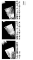
そして、試験片No.1〜4の組織中に分布する一次炭化物を評価した。まず、試験片の長さ方向(展伸方向)に対して平行である15mm×15mmの断面を指定して、この断面を、ダイヤモンドスラリーを用いて鏡面に研磨した。次に、この断面組織を観察したときの一次炭化物と基地との境界が明瞭になるように、10%ナイタールを用いて前記断面を腐食した。そして、この腐食後の断面を倍率200倍の光学顕微鏡で観察して、877μm×661μmの領域でなる1視野を20視野撮影した。図1は、試験片No.1〜4のそれぞれの断面を撮影した組織写真の一例である(一次炭化物は、白色の分布で示されている)。そして、この組織写真を画像処理することで、断面組織中に観察される円相当径が5μm以上の一次炭化物を抽出し、該断面組織中に占める一次炭化物の面積率を20視野分の平均値として求めた。 And test piece No. Primary carbides distributed in 1-4 structures were evaluated. First, a 15 mm × 15 mm cross section parallel to the length direction (stretching direction) of the test piece was specified, and this cross section was polished into a mirror surface using diamond slurry. Next, the cross section was corroded using 10% nital so that the boundary between the primary carbide and the base when the cross sectional structure was observed became clear. Then, the cross section after the corrosion was observed with an optical microscope having a magnification of 200 times, and 20 fields of view of a field of 877 μm × 661 μm were photographed. FIG. It is an example of the structure | tissue photograph which image | photographed each cross section of 1-4 (a primary carbide is shown by white distribution). Then, by processing this tissue photograph, primary carbides having an equivalent circle diameter of 5 μm or more observed in the cross-sectional structure are extracted, and the area ratio of the primary carbides in the cross-sectional structure is an average value for 20 fields of view. As sought.
そして、一次炭化物の分布状況を測定した後の試験片に対して、鋸刃による切断試験を実施して、その切断性を評価した。切断機には、株式会社アマダ製の鋸切断機PCSAW530AXを用いた。そして、鋸刃には、同社コーティング超硬合金製バンドソーブレードAXCELA G−NBN3Nを用いた。切断条件は、切削率16cm2/min、鋸速50m/min、送り5mm/minとした。And the cutting test by a saw blade was implemented with respect to the test piece after measuring the distribution condition of a primary carbide, and the cutting property was evaluated. As a cutting machine, a saw cutting machine PCSAW530AX manufactured by Amada Co., Ltd. was used. As the saw blade, a band saw blade AXCELA G-NBN3N made of the same coated cemented carbide was used. Cutting conditions were a cutting rate of 16 cm 2 / min, a sawing speed of 50 m / min, and a feed of 5 mm / min.
切断性の評価は、以下の手順により行った。まず、未使用の鋸刃を鋸切断機にセットした状態で、鋸刃の外観をマイクロスコープによって観察して、鋸刃に欠け等のないことを確認した。次に、ならし運転として、JIS−SKD11相当鋼の焼鈍材(硬さ20HRC)を累積切断面積が2000cm2に達するまで切断した。切断条件は、上記と同じとした。そして、ならし運転後の鋸刃の外観を再度観察して、鋸刃に摩耗や欠けが殆どないことを確認した後に、上記試験片の切断試験を実施した。尚、これを試験片毎に実施した。切断試験は、累積切断面積が4500cm2に達するまでを目標にして、連続して切断を行うものとし、累積切断面積が300cm2に達した毎に、切り曲がりを測定した。ここで、切り曲がりは、鋸全長の両端を結んだ直線(すなわち、所望の切断ライン)に対する、切断中の該直線と鋸刃(すなわち、実際の切断ライン)との隙間量(鋸刃のたわみ量)に反映されている。よって、本実施例では、前記切り曲がりの測定は、切断中の前記隙間量の測定に替えて、その最大および平均の隙間量(切り曲がり)を測定した。最大の隙間量とは、累積切断面積が300cm2に達した毎に測定して得た複数の最大隙間量のうちで、最も値の大きい隙間量である。平均の隙間量とは、前記複数の最大隙間量を平均した隙間量である。切り曲がりの測定結果を、上記試験片の硬度および一次炭化物の面積率と共に、表2に示す。The evaluation of cutting property was performed according to the following procedure. First, with an unused saw blade set in a saw cutter, the appearance of the saw blade was observed with a microscope, and it was confirmed that the saw blade was free of chipping. Next, as a leveling operation, an annealed material (hardness 20 HRC) of JIS-SKD11 equivalent steel was cut until the cumulative cutting area reached 2000 cm 2 . The cutting conditions were the same as above. Then, the appearance of the saw blade after the leveling operation was observed again, and it was confirmed that the saw blade had almost no wear or chipping, and then the above test piece was subjected to a cutting test. In addition, this was implemented for every test piece. In the cutting test, continuous cutting was performed until the cumulative cutting area reached 4500 cm 2 , and the bending was measured every time the cumulative cutting area reached 300 cm 2 . Here, the bending is the amount of gap between the straight line being cut and the saw blade (that is, the actual cutting line) with respect to the straight line that connects both ends of the entire length of the saw (that is, the desired cutting line) (the deflection of the saw blade). Amount). Therefore, in the present Example, the measurement of the said bending was replaced with the measurement of the said gap | interval amount during cutting | disconnection, and measured the maximum and the average gap | interval amount (bending). The maximum gap amount is a gap amount having the largest value among a plurality of maximum gap amounts obtained by measurement every time the cumulative cutting area reaches 300 cm 2 . The average gap amount is a gap amount obtained by averaging the plurality of maximum gap amounts. The measurement results of the bending are shown in Table 2 together with the hardness of the test piece and the area ratio of the primary carbide.
本発明例である試験片No.1、2は、その焼入れ焼戻し後の組織中において円相当径が5μm以上の一次炭化物が2面積%以下であった。そして、58HRC以上の高硬度の状態において、切断時の切り曲がりが最大値でも1mm未満に抑えられて、かつ、4500cm2の累積切断面積も達成され、良好な切断性を示した。これに対して、比較例である試験片No.3は、上記一次炭化物の面積率が2面積%を超えていた。そして、58HRC以上の高硬度の状態において、累積切断面積が4500cm2に達するまでの連続切断は可能であったが、切断時の切り曲がりが最大、平均の両値で1mm以上であった。さらに、比較例である試験片No.4は、上記一次炭化物の面積率が7面積%以上にも及んだ。そして、切断時には、その初期において、切断抵抗の上昇によって切断機のモーターに過大な負荷が掛かり、累計切断面積が480cm2に達した時点で切断機が停止し、事実上、切断が不可能であった。Test piece No. which is an example of the present invention. In Nos. 1 and 2, primary carbides having an equivalent circle diameter of 5 μm or more were 2 area% or less in the structure after quenching and tempering. And in the state of high hardness of 58HRC or more, the bending at the time of cutting was suppressed to less than 1 mm even at the maximum value, and a cumulative cutting area of 4500 cm 2 was achieved, showing good cutting properties. On the other hand, test piece No. which is a comparative example. In No. 3, the area ratio of the primary carbide exceeded 2 area%. In a state of high hardness of 58 HRC or higher, continuous cutting was possible until the cumulative cutting area reached 4500 cm 2 , but the bending at the time of cutting was the maximum, and the average value was 1 mm or more. Furthermore, test piece No. which is a comparative example. In No. 4, the area ratio of the primary carbide reached 7 area% or more. At the initial stage of cutting, an excessive load is applied to the motor of the cutting machine due to an increase in cutting resistance. When the cumulative cutting area reaches 480 cm 2 , the cutting machine stops, and cutting is virtually impossible. there were.
図2は、各試験片の切断に用いた鋸刃について、その切断試験終了後の逃げ面の1つをデジタルマイクロスコープで観察した写真である(但し、試験片No.4については、上記切断機が停止した時点での鋸刃の逃げ面である)。図2には、ならし運転後の鋸刃の逃げ面も示しておく。試験片No.1、2を切断した後の鋸刃の逃げ面は、試験片No.3のそれと比較して、摩耗が少なかった。そして、試験片No.4を切断した後の鋸刃の逃げ面は、切断試験が中断した時点で、既に著しい摩耗が生じていた。また、鋸刃の一部は欠けて、滅失していた。 2 is a photograph of one of the flank faces after the cutting test of the saw blade used for cutting each test piece observed with a digital microscope (however, for test piece No. 4, the above cutting is performed). This is the flank of the saw blade when the machine stops). FIG. 2 also shows the flank face of the saw blade after the leveling operation. Specimen No. The flank face of the saw blade after cutting 1 and 2 is the test piece no. Compared with that of No. 3, there was less wear. And test piece No. The flank of the saw blade after cutting 4 had already suffered significant wear when the cutting test was interrupted. Also, part of the saw blade was missing and lost.
表3の成分組成(つまり、表1の鋼塊No.3の成分組成)を有した鋼塊No.5を作製した。 Steel ingot Nos. Having the composition of Table 3 (that is, the composition of steel ingot No. 3 in Table 1). 5 was produced.
次に、鋼塊No.5に鍛造比が10程度の熱間鍛造を行って、鋼片を得た。そして、鋼片を冷却後、860℃で焼鈍した。そして、焼鈍後の鋼片から、切断性を評価するための試験片(つまり、切断前の鋼素材)No.5−A、5−Bを作製した。試験片の寸法は、長さ250mm(上記鍛造による展伸方向である)、幅300mm、厚さ150mmとした。次に、試験片No.5−Aには1170℃で10時間保持する固溶化熱処理を、試験片No.5−Bには1170℃で5時間保持する固溶化熱処理を、それぞれ実施した。そして、固溶化熱処理後の試験片において、その表面のうちの250mm×300mmの2面を除いた4面を研削して、前記4面の酸化膜を除去した。そして、前記研削後に、1030℃からの空冷による焼入れ処理と、500〜540℃で2回の焼戻し処理を実施して、60HRCの狙い硬度に調整した。 Next, the steel ingot No. 5 was subjected to hot forging with a forging ratio of about 10 to obtain a steel slab. And the steel slab was cooled and then annealed at 860 ° C. And the test piece (namely, steel material before a cutting | disconnection) No. for evaluating cutting property from the steel piece after annealing. 5-A and 5-B were produced. The dimensions of the test piece were 250 mm in length (in the extending direction by forging), 300 mm in width, and 150 mm in thickness. Next, test piece No. 5-A was subjected to a solution heat treatment that was maintained at 1170 ° C. for 10 hours. 5-B was subjected to a solid solution heat treatment at 1170 ° C. for 5 hours. Then, in the test piece after the solution heat treatment, four surfaces of the surface except for two surfaces of 250 mm × 300 mm were ground to remove the oxide film on the four surfaces. And after the said grinding, the quenching process by air cooling from 1030 degreeC and the tempering process twice at 500-540 degreeC were implemented, and it adjusted to the target hardness of 60 HRC.
前記硬度に調整した試験片No.5−A、5−Bの組織中に分布する一次炭化物を評価した。組織観察の要領は、前記実施例1と同じである。図3は、試験片No.5−A、5−Bのそれぞれの断面を撮影した組織写真の一例である(一次炭化物は、白色の分布で示されている)。そして、この組織写真を画像処理することで、断面組織中に観察される円相当径が5μm以上の一次炭化物を抽出し、該断面組織中に占める一次炭化物の面積率を20視野分の平均値として求めた。 Specimen No. adjusted to the hardness Primary carbides distributed in the 5-A and 5-B tissues were evaluated. The procedure for tissue observation is the same as in the first embodiment. FIG. It is an example of the structure | tissue photograph which image | photographed each cross section of 5-A and 5-B (a primary carbide is shown by white distribution). Then, by processing this tissue photograph, primary carbides having an equivalent circle diameter of 5 μm or more observed in the cross-sectional structure are extracted, and the area ratio of the primary carbides in the cross-sectional structure is an average value for 20 fields of view. As sought.
そして、一次炭化物の分布状況を測定した後の試験片に対して、鋸刃による切断試験を実施して、その切断性を評価した。切断試験の条件および切断性の評価要領は、前記実施例1のものに準じた。所定の累積切断面積に達したときの切り曲がりの測定結果を、上記試験片の硬度および一次炭化物の面積率と共に、表4に示す。 And the cutting test by a saw blade was implemented with respect to the test piece after measuring the distribution condition of a primary carbide, and the cutting property was evaluated. The conditions for the cutting test and the evaluation procedure for the cutting ability were the same as those in Example 1. Table 4 shows the measurement results of the bending when the predetermined cumulative cutting area is reached, together with the hardness of the test piece and the area ratio of the primary carbide.
本発明例である試験片No.5−A、5−Bは、共に、その焼入れ焼戻し後の組織中において円相当径が5μm以上の一次炭化物が2面積%以下であった。そして、58HRC以上の高硬度の状態において、切断時の切り曲がりが平均値で1mm未満に抑えられており、最大値でも1mm程度に抑えられており、かつ、累積切断面積も3600cm2以上を達成して、良好な切断性を示した。なお、試験片No.5−Bは、前記5μm以上の一次炭化物の面積率が高めであったことから、切断抵抗の上昇を考慮して、累計切断面積が3600cm2に達した時点で切断試験を終了した。そして、それまでの切断時における切り曲がりは、最大値でも0.25mmに留まっていた。ここで、実施例1で行った比較例である試験片No.3の切断結果は、その累積切断面積が3600cm2に達したときの切り曲がりが平均値で1.06mm、最大値で1.57mmであった。このことと比較して、試験片No.5−Bであっても、良好な切断性を有していることを確認できた。Test piece No. which is an example of the present invention. In 5-A and 5-B, primary carbides having an equivalent circle diameter of 5 μm or more were 2 area% or less in the structure after quenching and tempering. In a high hardness state of 58HRC or higher, the bending at the time of cutting is suppressed to an average value of less than 1 mm, the maximum value is suppressed to about 1 mm, and the cumulative cutting area is also 3600 cm 2 or more. As a result, good cutting properties were shown. The test piece No. In 5-B, since the area ratio of the primary carbide of 5 μm or more was high, the cutting test was finished when the cumulative cutting area reached 3600 cm 2 in consideration of the increase in cutting resistance. And the bending at the time of cutting until then has remained at 0.25 mm even at the maximum value. Here, test piece No. which is a comparative example performed in Example 1. As for the cutting result of No. 3 , when the cumulative cutting area reached 3600 cm 2 , the average bending was 1.06 mm and the maximum was 1.57 mm. In comparison with this, test piece No. Even if it was 5-B, it has confirmed that it had favorable cutting property.
図4は、試験片No.5−A、5−Bの切断に用いた鋸刃について、その切断試験終了後の逃げ面の1つをデジタルマイクロスコープで観察した写真である。図4には、ならし運転後の鋸刃の逃げ面も示しておく。試験片No.5−A、5−Bを切断した後の鋸刃の逃げ面は、摩耗が少なかった。そして、4500cm2の同じ累積切断面積に達するまで切断したときの前記逃げ面の間で比較すると、試験片No.5−Aを切断した後の鋸刃の逃げ面は、実施例1における試験片No.1、2(本発明例)の前記逃げ面より、摩耗が多めであった。しかし、試験片No.3(比較例)の前記逃げ面と比較すると、摩耗は少なかった。FIG. It is the photograph which observed one of the flank after the end of the cutting test about the saw blade used for the cutting of 5-A and 5-B with a digital microscope. FIG. 4 also shows the flank face of the saw blade after the leveling operation. Specimen No. The flank of the saw blade after cutting 5-A and 5-B was less worn. And when it compares between the said flank when it cut | disconnects until it reaches the same cumulative cutting area of 4500 cm < 2 >, test piece No.1. The flank face of the saw blade after cutting 5-A is the test piece No. 1 in Example 1. There was much wear from the said flank of 1 and 2 (invention example). However, specimen no. There was little abrasion compared with the said flank of 3 (comparative example).
図5は、実施例1、2で各試験片を切断した後の上記鋸刃について、その逃げ面1つあたりに生じた平均の摩耗面積を示したグラフ図である。なお、図5では、試験片No.1、2、3、4、5−A、5−Bのそれぞれを切断した鋸刃の逃げ面に対して、逃げ面1、2、3、4、5−A、5−Bと表記している。鋸刃の逃げ面の摩耗面積は、切断した試験片組織中の上記一次炭化物量の減少に従って、少なくなる傾向であった。以上の結果より、切断後の鋼素材に生じた切り曲がりや、鋸刃の損耗の程度は、切断した鋼素材中の粗大な一次炭化物の面積率と相関があることが認められた。 FIG. 5 is a graph showing the average wear area generated per flank for the saw blade after cutting each test piece in Examples 1 and 2. FIG. In addition, in FIG. 1, 2, 3, 4, 5-A, and 5-B, the flank face of the saw blade cut, and the flank face 1, 2, 3, 4, 5-A, 5-B. Yes. The wear area of the flank face of the saw blade tended to decrease as the amount of primary carbide in the cut specimen structure decreased. From the above results, it was recognized that the degree of bending and saw blade wear generated in the steel material after cutting correlated with the area ratio of coarse primary carbides in the cut steel material.
Claims (5)
鋼塊を熱間加工して、鋼片を得る第1工程と、
前記第1工程で得た鋼片の表面には酸化被膜が形成されており、前記酸化被膜の少なくとも一部が残存する鋼片に焼入れおよび焼戻しを実施して、硬さが58HRC以上であり、断面組織中における円相当径で5μm以上の一次炭化物が2面積%以下である鋼素材を得る第2工程と、
を備えることを特徴とする金型用鋼素材の製造方法。 A method of manufacturing a steel material used for manufacturing a cold working mold having a hardness of 58 HRC or more, which is used after being cut into a pre-hardened steel material having a size corresponding to the dimensions of the cold working mold. A method of manufacturing a steel material,
A first step of hot working a steel ingot to obtain a steel piece;
An oxide film is formed on the surface of the steel piece obtained in the first step, the steel piece where at least a part of the oxide film remains is quenched and tempered, and the hardness is 58 HRC or more, A second step of obtaining a steel material in which the primary carbide in the cross-sectional structure has a circle equivalent diameter of 5 μm or more and 2% by area or less;
A method for producing a steel material for a mold, comprising:
Applications Claiming Priority (3)
| Application Number | Priority Date | Filing Date | Title |
|---|---|---|---|
| JP2013074239 | 2013-03-29 | ||
| JP2013074239 | 2013-03-29 | ||
| PCT/JP2014/055274 WO2014156487A1 (en) | 2013-03-29 | 2014-03-03 | Steel material for die and process for producing same, process for producing prehardened steel product for die, and process for producing cold working die |
Related Child Applications (1)
| Application Number | Title | Priority Date | Filing Date |
|---|---|---|---|
| JP2015227417A Division JP6041231B2 (en) | 2013-03-29 | 2015-11-20 | Manufacturing method of pre-hardened steel for mold and manufacturing method of cold working mold |
Publications (2)
| Publication Number | Publication Date |
|---|---|
| JP6032582B2 true JP6032582B2 (en) | 2016-11-30 |
| JPWO2014156487A1 JPWO2014156487A1 (en) | 2017-02-16 |
Family
ID=51623478
Family Applications (2)
| Application Number | Title | Priority Date | Filing Date |
|---|---|---|---|
| JP2015508213A Active JP6032582B2 (en) | 2013-03-29 | 2014-03-03 | Manufacturing method of steel material for mold |
| JP2015227417A Active JP6041231B2 (en) | 2013-03-29 | 2015-11-20 | Manufacturing method of pre-hardened steel for mold and manufacturing method of cold working mold |
Family Applications After (1)
| Application Number | Title | Priority Date | Filing Date |
|---|---|---|---|
| JP2015227417A Active JP6041231B2 (en) | 2013-03-29 | 2015-11-20 | Manufacturing method of pre-hardened steel for mold and manufacturing method of cold working mold |
Country Status (3)
| Country | Link |
|---|---|
| EP (1) | EP2979772B1 (en) |
| JP (2) | JP6032582B2 (en) |
| WO (1) | WO2014156487A1 (en) |
Cited By (1)
| Publication number | Priority date | Publication date | Assignee | Title |
|---|---|---|---|---|
| CN109280849A (en) * | 2018-10-26 | 2019-01-29 | 如皋市宏茂重型锻压有限公司 | A kind of high performance hot-work die steel and its manufacturing process |
Families Citing this family (5)
| Publication number | Priority date | Publication date | Assignee | Title |
|---|---|---|---|---|
| JP6519226B2 (en) * | 2015-02-26 | 2019-05-29 | 大同特殊鋼株式会社 | Alloy tool steel |
| CN107427893B (en) * | 2015-03-26 | 2019-06-11 | 日立金属株式会社 | Cold-working tool and its manufacturing method |
| CN111229950A (en) * | 2018-11-29 | 2020-06-05 | 苏州玉田精密模具有限公司 | Processing technique for punching female die core rod of discharge hole collecting pipe |
| CN111940611A (en) * | 2020-08-07 | 2020-11-17 | 和县卜集振兴标准件厂 | Method for improving precision of alloy steel stamping die |
| CN117660734A (en) * | 2024-01-31 | 2024-03-08 | 成都先进金属材料产业技术研究院股份有限公司 | Cold work die steel surface strengthening treatment method and cold work die steel |
Citations (7)
| Publication number | Priority date | Publication date | Assignee | Title |
|---|---|---|---|---|
| JPH0892657A (en) * | 1994-09-29 | 1996-04-09 | Daido Steel Co Ltd | Production of prehardened steel bar and apparatus for producing the same |
| JP2001020041A (en) * | 1999-07-08 | 2001-01-23 | Hitachi Metals Ltd | Tool steel excellent in weldability and machinability and tool and die |
| JP2001049394A (en) * | 1999-08-17 | 2001-02-20 | Hitachi Metals Ltd | Tool steel excellent in weldability and machinability, and die using the same |
| JP2001294974A (en) * | 2000-04-12 | 2001-10-26 | Hitachi Metals Ltd | Tool steel excellent in machinability and small in dimensional change cause by heat treatment and its producing method |
| JP2006150487A (en) * | 2004-11-29 | 2006-06-15 | Nachi Fujikoshi Corp | Saw blade |
| WO2012043228A1 (en) * | 2010-09-27 | 2012-04-05 | 日立金属株式会社 | High-hardness pre-hardened cold-rolled tool steel for surface pvd, method for producing same, and surface pvd method for same |
| WO2012115025A1 (en) * | 2011-02-21 | 2012-08-30 | 日立金属株式会社 | Manufacturing method for cold-working die |
Family Cites Families (11)
| Publication number | Priority date | Publication date | Assignee | Title |
|---|---|---|---|---|
| CN1097642C (en) * | 1999-07-30 | 2003-01-01 | 日立金属株式会社 | Tool steel with good weldability, machinability and thermal treatment property, and metallic mould made of same |
| JP3365624B2 (en) | 1999-07-30 | 2003-01-14 | 日立金属株式会社 | Tool steel with excellent machinability and heat treatment and mold using the tool steel |
| JP2001129722A (en) | 1999-11-01 | 2001-05-15 | Amada Eng Center Co Ltd | Saw blade |
| JP2001316769A (en) | 2000-05-10 | 2001-11-16 | Daido Steel Co Ltd | Cold tool steel |
| JP3883788B2 (en) | 2000-06-29 | 2007-02-21 | 山陽特殊製鋼株式会社 | Cold tool steel for molds with excellent toughness and wear resistance |
| JP3830030B2 (en) * | 2000-12-13 | 2006-10-04 | 日立金属株式会社 | High-hardness pre-hardened steel for cold working with excellent machinability, cold working mold using the same, and method for machining steel |
| JP4093978B2 (en) | 2004-03-23 | 2008-06-04 | 日本高周波鋼業株式会社 | Tool steel with self-lubricating properties |
| JP2006193790A (en) | 2005-01-14 | 2006-07-27 | Daido Steel Co Ltd | Cold working tool steel |
| JP2008189982A (en) | 2007-02-02 | 2008-08-21 | Daido Steel Co Ltd | Tool steel |
| JP5338188B2 (en) | 2007-10-31 | 2013-11-13 | 大同特殊鋼株式会社 | Alloy tool steel and manufacturing method thereof |
| JP5672466B2 (en) | 2011-02-21 | 2015-02-18 | 日立金属株式会社 | Cold work tool steel with excellent machinability |
-
2014
- 2014-03-03 JP JP2015508213A patent/JP6032582B2/en active Active
- 2014-03-03 EP EP14776113.4A patent/EP2979772B1/en active Active
- 2014-03-03 WO PCT/JP2014/055274 patent/WO2014156487A1/en active Application Filing
-
2015
- 2015-11-20 JP JP2015227417A patent/JP6041231B2/en active Active
Patent Citations (7)
| Publication number | Priority date | Publication date | Assignee | Title |
|---|---|---|---|---|
| JPH0892657A (en) * | 1994-09-29 | 1996-04-09 | Daido Steel Co Ltd | Production of prehardened steel bar and apparatus for producing the same |
| JP2001020041A (en) * | 1999-07-08 | 2001-01-23 | Hitachi Metals Ltd | Tool steel excellent in weldability and machinability and tool and die |
| JP2001049394A (en) * | 1999-08-17 | 2001-02-20 | Hitachi Metals Ltd | Tool steel excellent in weldability and machinability, and die using the same |
| JP2001294974A (en) * | 2000-04-12 | 2001-10-26 | Hitachi Metals Ltd | Tool steel excellent in machinability and small in dimensional change cause by heat treatment and its producing method |
| JP2006150487A (en) * | 2004-11-29 | 2006-06-15 | Nachi Fujikoshi Corp | Saw blade |
| WO2012043228A1 (en) * | 2010-09-27 | 2012-04-05 | 日立金属株式会社 | High-hardness pre-hardened cold-rolled tool steel for surface pvd, method for producing same, and surface pvd method for same |
| WO2012115025A1 (en) * | 2011-02-21 | 2012-08-30 | 日立金属株式会社 | Manufacturing method for cold-working die |
Cited By (1)
| Publication number | Priority date | Publication date | Assignee | Title |
|---|---|---|---|---|
| CN109280849A (en) * | 2018-10-26 | 2019-01-29 | 如皋市宏茂重型锻压有限公司 | A kind of high performance hot-work die steel and its manufacturing process |
Also Published As
| Publication number | Publication date |
|---|---|
| JPWO2014156487A1 (en) | 2017-02-16 |
| JP6041231B2 (en) | 2016-12-07 |
| EP2979772B1 (en) | 2018-09-05 |
| JP2016106176A (en) | 2016-06-16 |
| WO2014156487A1 (en) | 2014-10-02 |
| EP2979772A1 (en) | 2016-02-03 |
| EP2979772A4 (en) | 2016-10-12 |
Similar Documents
| Publication | Publication Date | Title |
|---|---|---|
| JP6041231B2 (en) | Manufacturing method of pre-hardened steel for mold and manufacturing method of cold working mold | |
| JP5843173B2 (en) | Manufacturing method of cold working mold | |
| JP2007009321A (en) | Steel for plastic molding die | |
| JP2007197746A (en) | Tool steel | |
| JP4737606B2 (en) | Cold die steel with excellent deformation suppression characteristics and galling resistance | |
| JP2006328521A (en) | Tool for precision working and tool steel | |
| JP2008189982A (en) | Tool steel | |
| JPWO2016208571A1 (en) | Method for producing high-speed tool steel material, method for producing high-speed tool steel product, and high-speed tool steel product | |
| KR20180072778A (en) | Steel, carburizing steel parts and manufacturing method of carburizing steel parts | |
| JP2019116678A (en) | Prehardened steel material, mold and mold component | |
| JP5186878B2 (en) | Steel for plastic molds and plastic molds | |
| JP6590213B2 (en) | Manufacturing method of cold working mold | |
| JP4860774B1 (en) | Cold work tool steel | |
| WO2016075951A1 (en) | Hot work tool steel | |
| JP2014031575A (en) | Steel for high hardness cold die and manufacturing method thereof | |
| JP5273952B2 (en) | Hot forging die and manufacturing method thereof | |
| JP4984321B2 (en) | Pre-hardened steel excellent in machinability and toughness and method for producing the same | |
| JP6597078B2 (en) | Steel pipe for machine structural members with excellent machinability and manufacturing method thereof | |
| JP2005082813A (en) | Prehardened steel for plastic molding die | |
| JP5668942B2 (en) | Die steel excellent in hole workability and suppression of machining strain and method for producing the same | |
| JP5597999B2 (en) | Cold work tool steel with excellent machinability | |
| JP6650104B2 (en) | Cold tool material and cold tool manufacturing method | |
| JP6416624B2 (en) | Method for cutting cold tool steel and method for producing cold mold material | |
| TWI647318B (en) | Steel for cold working tool | |
| JP2016156081A (en) | Alloy tool steel |
Legal Events
| Date | Code | Title | Description |
|---|---|---|---|
| A521 | Request for written amendment filed |
Free format text: JAPANESE INTERMEDIATE CODE: A523 Effective date: 20160826 |
|
| TRDD | Decision of grant or rejection written | ||
| A01 | Written decision to grant a patent or to grant a registration (utility model) |
Free format text: JAPANESE INTERMEDIATE CODE: A01 Effective date: 20160930 |
|
| A61 | First payment of annual fees (during grant procedure) |
Free format text: JAPANESE INTERMEDIATE CODE: A61 Effective date: 20161013 |
|
| R150 | Certificate of patent or registration of utility model |
Ref document number: 6032582 Country of ref document: JP Free format text: JAPANESE INTERMEDIATE CODE: R150 |
|
| S531 | Written request for registration of change of domicile |
Free format text: JAPANESE INTERMEDIATE CODE: R313531 |
|
| S533 | Written request for registration of change of name |
Free format text: JAPANESE INTERMEDIATE CODE: R313533 |
|
| R350 | Written notification of registration of transfer |
Free format text: JAPANESE INTERMEDIATE CODE: R350 |