JP6032233B2 - Solid battery and manufacturing method thereof, and assembled battery and manufacturing method thereof - Google Patents
Solid battery and manufacturing method thereof, and assembled battery and manufacturing method thereof Download PDFInfo
- Publication number
- JP6032233B2 JP6032233B2 JP2014055299A JP2014055299A JP6032233B2 JP 6032233 B2 JP6032233 B2 JP 6032233B2 JP 2014055299 A JP2014055299 A JP 2014055299A JP 2014055299 A JP2014055299 A JP 2014055299A JP 6032233 B2 JP6032233 B2 JP 6032233B2
- Authority
- JP
- Japan
- Prior art keywords
- solid
- battery
- pressure
- electrode layer
- pressure receiving
- Prior art date
- Legal status (The legal status is an assumption and is not a legal conclusion. Google has not performed a legal analysis and makes no representation as to the accuracy of the status listed.)
- Active
Links
Images


Classifications
-
- H—ELECTRICITY
- H01—ELECTRIC ELEMENTS
- H01M—PROCESSES OR MEANS, e.g. BATTERIES, FOR THE DIRECT CONVERSION OF CHEMICAL ENERGY INTO ELECTRICAL ENERGY
- H01M10/00—Secondary cells; Manufacture thereof
- H01M10/04—Construction or manufacture in general
- H01M10/0413—Large-sized flat cells or batteries for motive or stationary systems with plate-like electrodes
-
- H—ELECTRICITY
- H01—ELECTRIC ELEMENTS
- H01M—PROCESSES OR MEANS, e.g. BATTERIES, FOR THE DIRECT CONVERSION OF CHEMICAL ENERGY INTO ELECTRICAL ENERGY
- H01M10/00—Secondary cells; Manufacture thereof
- H01M10/04—Construction or manufacture in general
- H01M10/0468—Compression means for stacks of electrodes and separators
-
- H—ELECTRICITY
- H01—ELECTRIC ELEMENTS
- H01M—PROCESSES OR MEANS, e.g. BATTERIES, FOR THE DIRECT CONVERSION OF CHEMICAL ENERGY INTO ELECTRICAL ENERGY
- H01M10/00—Secondary cells; Manufacture thereof
- H01M10/42—Methods or arrangements for servicing or maintenance of secondary cells or secondary half-cells
- H01M10/48—Accumulators combined with arrangements for measuring, testing or indicating the condition of cells, e.g. the level or density of the electrolyte
- H01M10/482—Accumulators combined with arrangements for measuring, testing or indicating the condition of cells, e.g. the level or density of the electrolyte for several batteries or cells simultaneously or sequentially
-
- H—ELECTRICITY
- H01—ELECTRIC ELEMENTS
- H01M—PROCESSES OR MEANS, e.g. BATTERIES, FOR THE DIRECT CONVERSION OF CHEMICAL ENERGY INTO ELECTRICAL ENERGY
- H01M10/00—Secondary cells; Manufacture thereof
- H01M10/05—Accumulators with non-aqueous electrolyte
- H01M10/052—Li-accumulators
-
- H—ELECTRICITY
- H01—ELECTRIC ELEMENTS
- H01M—PROCESSES OR MEANS, e.g. BATTERIES, FOR THE DIRECT CONVERSION OF CHEMICAL ENERGY INTO ELECTRICAL ENERGY
- H01M10/00—Secondary cells; Manufacture thereof
- H01M10/05—Accumulators with non-aqueous electrolyte
- H01M10/056—Accumulators with non-aqueous electrolyte characterised by the materials used as electrolytes, e.g. mixed inorganic/organic electrolytes
- H01M10/0561—Accumulators with non-aqueous electrolyte characterised by the materials used as electrolytes, e.g. mixed inorganic/organic electrolytes the electrolyte being constituted of inorganic materials only
- H01M10/0562—Solid materials
-
- H—ELECTRICITY
- H01—ELECTRIC ELEMENTS
- H01M—PROCESSES OR MEANS, e.g. BATTERIES, FOR THE DIRECT CONVERSION OF CHEMICAL ENERGY INTO ELECTRICAL ENERGY
- H01M10/00—Secondary cells; Manufacture thereof
- H01M10/05—Accumulators with non-aqueous electrolyte
- H01M10/058—Construction or manufacture
- H01M10/0585—Construction or manufacture of accumulators having only flat construction elements, i.e. flat positive electrodes, flat negative electrodes and flat separators
-
- H—ELECTRICITY
- H01—ELECTRIC ELEMENTS
- H01M—PROCESSES OR MEANS, e.g. BATTERIES, FOR THE DIRECT CONVERSION OF CHEMICAL ENERGY INTO ELECTRICAL ENERGY
- H01M2220/00—Batteries for particular applications
- H01M2220/20—Batteries in motive systems, e.g. vehicle, ship, plane
-
- H—ELECTRICITY
- H01—ELECTRIC ELEMENTS
- H01M—PROCESSES OR MEANS, e.g. BATTERIES, FOR THE DIRECT CONVERSION OF CHEMICAL ENERGY INTO ELECTRICAL ENERGY
- H01M2300/00—Electrolytes
- H01M2300/0017—Non-aqueous electrolytes
- H01M2300/0065—Solid electrolytes
-
- H—ELECTRICITY
- H01—ELECTRIC ELEMENTS
- H01M—PROCESSES OR MEANS, e.g. BATTERIES, FOR THE DIRECT CONVERSION OF CHEMICAL ENERGY INTO ELECTRICAL ENERGY
- H01M50/00—Constructional details or processes of manufacture of the non-active parts of electrochemical cells other than fuel cells, e.g. hybrid cells
- H01M50/10—Primary casings, jackets or wrappings of a single cell or a single battery
- H01M50/102—Primary casings, jackets or wrappings of a single cell or a single battery characterised by their shape or physical structure
- H01M50/103—Primary casings, jackets or wrappings of a single cell or a single battery characterised by their shape or physical structure prismatic or rectangular
-
- H—ELECTRICITY
- H01—ELECTRIC ELEMENTS
- H01M—PROCESSES OR MEANS, e.g. BATTERIES, FOR THE DIRECT CONVERSION OF CHEMICAL ENERGY INTO ELECTRICAL ENERGY
- H01M50/00—Constructional details or processes of manufacture of the non-active parts of electrochemical cells other than fuel cells, e.g. hybrid cells
- H01M50/20—Mountings; Secondary casings or frames; Racks, modules or packs; Suspension devices; Shock absorbers; Transport or carrying devices; Holders
- H01M50/204—Racks, modules or packs for multiple batteries or multiple cells
- H01M50/207—Racks, modules or packs for multiple batteries or multiple cells characterised by their shape
- H01M50/209—Racks, modules or packs for multiple batteries or multiple cells characterised by their shape adapted for prismatic or rectangular cells
-
- H—ELECTRICITY
- H01—ELECTRIC ELEMENTS
- H01M—PROCESSES OR MEANS, e.g. BATTERIES, FOR THE DIRECT CONVERSION OF CHEMICAL ENERGY INTO ELECTRICAL ENERGY
- H01M50/00—Constructional details or processes of manufacture of the non-active parts of electrochemical cells other than fuel cells, e.g. hybrid cells
- H01M50/20—Mountings; Secondary casings or frames; Racks, modules or packs; Suspension devices; Shock absorbers; Transport or carrying devices; Holders
- H01M50/218—Mountings; Secondary casings or frames; Racks, modules or packs; Suspension devices; Shock absorbers; Transport or carrying devices; Holders characterised by the material
- H01M50/22—Mountings; Secondary casings or frames; Racks, modules or packs; Suspension devices; Shock absorbers; Transport or carrying devices; Holders characterised by the material of the casings or racks
- H01M50/227—Organic material
-
- Y—GENERAL TAGGING OF NEW TECHNOLOGICAL DEVELOPMENTS; GENERAL TAGGING OF CROSS-SECTIONAL TECHNOLOGIES SPANNING OVER SEVERAL SECTIONS OF THE IPC; TECHNICAL SUBJECTS COVERED BY FORMER USPC CROSS-REFERENCE ART COLLECTIONS [XRACs] AND DIGESTS
- Y02—TECHNOLOGIES OR APPLICATIONS FOR MITIGATION OR ADAPTATION AGAINST CLIMATE CHANGE
- Y02E—REDUCTION OF GREENHOUSE GAS [GHG] EMISSIONS, RELATED TO ENERGY GENERATION, TRANSMISSION OR DISTRIBUTION
- Y02E60/00—Enabling technologies; Technologies with a potential or indirect contribution to GHG emissions mitigation
- Y02E60/10—Energy storage using batteries
-
- Y—GENERAL TAGGING OF NEW TECHNOLOGICAL DEVELOPMENTS; GENERAL TAGGING OF CROSS-SECTIONAL TECHNOLOGIES SPANNING OVER SEVERAL SECTIONS OF THE IPC; TECHNICAL SUBJECTS COVERED BY FORMER USPC CROSS-REFERENCE ART COLLECTIONS [XRACs] AND DIGESTS
- Y02—TECHNOLOGIES OR APPLICATIONS FOR MITIGATION OR ADAPTATION AGAINST CLIMATE CHANGE
- Y02P—CLIMATE CHANGE MITIGATION TECHNOLOGIES IN THE PRODUCTION OR PROCESSING OF GOODS
- Y02P70/00—Climate change mitigation technologies in the production process for final industrial or consumer products
- Y02P70/50—Manufacturing or production processes characterised by the final manufactured product
-
- Y—GENERAL TAGGING OF NEW TECHNOLOGICAL DEVELOPMENTS; GENERAL TAGGING OF CROSS-SECTIONAL TECHNOLOGIES SPANNING OVER SEVERAL SECTIONS OF THE IPC; TECHNICAL SUBJECTS COVERED BY FORMER USPC CROSS-REFERENCE ART COLLECTIONS [XRACs] AND DIGESTS
- Y10—TECHNICAL SUBJECTS COVERED BY FORMER USPC
- Y10T—TECHNICAL SUBJECTS COVERED BY FORMER US CLASSIFICATION
- Y10T29/00—Metal working
- Y10T29/49—Method of mechanical manufacture
- Y10T29/49002—Electrical device making
- Y10T29/49108—Electric battery cell making
Landscapes
- Engineering & Computer Science (AREA)
- Manufacturing & Machinery (AREA)
- Chemical & Material Sciences (AREA)
- Chemical Kinetics & Catalysis (AREA)
- Electrochemistry (AREA)
- General Chemical & Material Sciences (AREA)
- Secondary Cells (AREA)
- Battery Mounting, Suspending (AREA)
- Primary Cells (AREA)
Description
本発明は、固体電池及びその製造方法並びに複数の固体電池を含む組電池及びその製造方法に関する。 The present invention relates to a solid battery, a manufacturing method thereof, an assembled battery including a plurality of solid batteries, and a manufacturing method thereof.
電解質が固体電解質から成る固体電池は、電池内に可燃性の有機溶媒を用いないため、安全装置の簡素化が図れ、製造コストや生産性に優れると考えられている。特に、近年、ハイブリッド自動車、電気自動車等の需要が高まるにつれて、固体電池について、安全性に加えて容量及び出力の向上を図ることが求められている。固体電池の製造方法として、特許文献1には、集電体と正極層又は負極層との間の剥離を防止するために、正極集電体、正極層、電解質層、負極層、及び負極集電体をこの順序で積層することにより積層体を作製した後、この積層体を積層方向に加圧したまま拘束することを含む方法が提案されている。また、特許文献2には、正極と負極と正極及び負極の間に介在する電解質を有する発電要素(単電池)に対する加圧力を、発電要素を収容する密閉容器内に充填された流体により調整することが提案されている。さらに、特許文献3には、車両の走行状態に応じて、蓄電池に加える圧力を圧力調整装置により調整することにより、蓄電池の放電電流を最大値に調整する走行制御手段を備えた車両駆動装置が提案されている。
A solid battery in which the electrolyte is a solid electrolyte does not use a flammable organic solvent in the battery, so that it is considered that the safety device can be simplified and that the manufacturing cost and productivity are excellent. In particular, as demand for hybrid vehicles, electric vehicles, and the like increases in recent years, it is required to improve the capacity and output of solid batteries in addition to safety. As a method for producing a solid state battery,
上記のように、電池の製造時又は使用時(車両の走行時)に、正極層、電解質層及び負極層の積層体を加圧することが提案されているが、かかる積層体を含む固体電池を複数積層した組電池の製造の際又はそれらの固体電池もしくは組電池の使用の際に、製造装置又は圧力調整装置の制御システムなどの障害によりかかる積層体又は固体電池が過剰に加圧された場合に、電池の破壊、過剰出力などの不具合が発生するおそれがあった。 As described above, it has been proposed to pressurize the laminate of the positive electrode layer, the electrolyte layer, and the negative electrode layer at the time of manufacturing or using the battery (during vehicle travel). When a laminated battery or a solid battery is excessively pressed due to a failure of a control system of a manufacturing apparatus or a pressure regulator, when manufacturing a plurality of laminated batteries or using those solid batteries or assembled batteries In addition, there is a risk of problems such as battery destruction and excessive output.
本発明は、上記の課題に鑑みてなされたものであり、電池の製造時又は使用時に、正極層、電解質層及び負極層の積層体が過剰に加圧されることを防止することによって、電池の破壊、過剰出力などの不具合が発生することを防止し、高い容量及び出力密度を有することに加えて、信頼性、耐久性などの性能特性に優れた固体電池及びその製造方法を提供することを目的とする。
本発明は、複数の固体電池を含む組電池及びその製造方法を提供することを目的とする。
The present invention has been made in view of the above-described problems, and prevents the battery stack from being over-pressurized during manufacture or use of the battery, thereby preventing the battery from being excessively pressurized. In addition to having a high capacity and output density, it is possible to provide a solid battery with excellent performance characteristics such as reliability and durability, and a method for manufacturing the same. With the goal.
An object of this invention is to provide the assembled battery containing a some solid battery, and its manufacturing method.
すなわち、本発明は、一実施形態において、正極活物質を含む正極層と、負極活物質を含む負極層と、正極層と負極層の間に積層された固体電解質層とを含む単電池を少なくとも1つ含む積層体と、当該積層体を収容する外装体を含む固体電池であって、当該固体電池は、さらに、外装体の周縁部の少なくとも一部に設けられた受圧部を含み、当該受圧部が、単電池の積層方向において積層体と外装体の合計厚み未満の厚みを有することを特徴とする固体電池を提供する。 That is, in one embodiment, the present invention provides at least a unit cell including a positive electrode layer including a positive electrode active material, a negative electrode layer including a negative electrode active material, and a solid electrolyte layer laminated between the positive electrode layer and the negative electrode layer. A solid battery including a laminated body including one and an exterior body that accommodates the laminated body, wherein the solid battery further includes a pressure receiving portion provided in at least a part of a peripheral portion of the exterior body, The solid battery is characterized in that the portion has a thickness less than the total thickness of the laminate and the outer package in the stacking direction of the unit cells.
本発明は、別の実施形態において、上記固体電池の製造方法であって、
(a)正極活物質を含む正極層と、負極活物質を含む負極層と、正極層と負極層の間に積層された固体電解質層とを含む単電池を少なくとも1つ含む積層体を形成する工程;
(b)上記積層体を外装体に収容する工程;及び
(c)上記外装体の周縁部の少なくとも一部に、上記単電池の積層方向において上記積層体と外装体の合計厚み未満の厚みを有する受圧部を形成する工程;
を含む方法を提供する。
In another embodiment, the present invention provides a method for producing the above solid battery,
(A) A laminate including at least one unit cell including a positive electrode layer including a positive electrode active material, a negative electrode layer including a negative electrode active material, and a solid electrolyte layer stacked between the positive electrode layer and the negative electrode layer is formed. Process;
(B) a step of accommodating the laminated body in an exterior body; and (c) a thickness less than a total thickness of the laminated body and the exterior body in at least a part of a peripheral portion of the exterior body in the stacking direction of the unit cells. Forming a pressure receiving portion having:
A method comprising:
本発明は、別の実施形態において、上記固体電池を複数含み、固体電池が上記積層体の積層方向と同一方向に積層されている組電池を提供する。 In another embodiment, the present invention provides an assembled battery including a plurality of the solid batteries, wherein the solid batteries are stacked in the same direction as the stacking direction of the stacked body.
本発明は、別の実施形態において、複数の固体電池を含む組電池の製造方法であって、
(i)正極活物質を含む正極層と、負極活物質を含む負極層と、正極層と負極層の間に積層された固体電解質層とを含む単電池を少なくとも1つ含む積層体と、
上記積層体を収容する外装体、
を含む固体電池であって、当該固体電池は、さらに、上記外装体の周縁部の少なくとも一部に設けられた受圧部を含み、当該受圧部が、上記単電池の積層方向において上記積層体と外装体の合計厚み未満の厚みを有する固体電池を複数用意する工程;
(ii)上記複数の固体電池を、当該複数の固体電池の受圧部が積層方向に沿って互いに間隔を開けて直列に並んで配置されるように積層する工程、ここで、複数の固体電池の各々を構成する正極層と固体電解質層と負極層の積層方向と複数の固体電池の積層方向は同一である;及び
(iii)上記複数の固体電池を積層方向に加圧する工程;
を含む方法を提供する。
In another embodiment, the present invention is a method of manufacturing an assembled battery including a plurality of solid state batteries,
(I) a laminate including at least one unit cell including a positive electrode layer including a positive electrode active material, a negative electrode layer including a negative electrode active material, and a solid electrolyte layer stacked between the positive electrode layer and the negative electrode layer;
An exterior body that houses the laminate,
The solid battery further includes a pressure receiving portion provided in at least a part of the peripheral portion of the exterior body, and the pressure receiving portion is the same as the stacked body in the stacking direction of the unit cells. Preparing a plurality of solid batteries having a thickness less than the total thickness of the outer package;
(Ii) a step of stacking the plurality of solid state batteries so that the pressure receiving portions of the plurality of solid state batteries are arranged in series at intervals from each other in the stacking direction, The stacking direction of each of the positive electrode layer, the solid electrolyte layer, and the negative electrode layer and the stacking direction of the plurality of solid batteries are the same; and (iii) a step of pressing the plurality of solid batteries in the stacking direction;
A method comprising:
本発明は、さらに別の実施形態において、
上記の組電池と、
組電池を構成する複数の固体電池の積層方向に組電池を加圧するための加圧装置と、
組電池を構成する複数の固体電池が積層方向に加圧されることにより圧縮されたことに応じて複数の固体電池の複数の受圧部が互いに接触したことを積層方向における複数の受圧部の通電により検知するための通電検知装置と、
を含む蓄電装置を提供する。
In yet another embodiment, the present invention provides:
The above assembled battery;
A pressurizing device for pressurizing the assembled battery in the stacking direction of a plurality of solid state batteries constituting the assembled battery;
Energization of the plurality of pressure-receiving portions in the stacking direction indicates that the plurality of pressure-receiving portions of the plurality of solid-state batteries are in contact with each other in response to the compression of the plurality of solid-state batteries constituting the assembled battery in the stacking direction. An energization detection device for detecting by,
A power storage device including the above is provided.
以下、本発明の実施形態について、図面を参照して説明する。なお、以下で参照する図面では、同一又は対応する要素には同じ参照番号が付されている。
[固体電池]
本発明の固体電池は、上記のとおり、正極層と、負極層と、正極層と負極層の間に積層された固体電解質層とを含む単電池を少なくとも1つ含む積層体を含む固体電池であって、さらに、単電池の積層方向に積層体に対して過剰な圧力が加わるのを防止するための受圧部を有することを特徴とするものである。
Hereinafter, embodiments of the present invention will be described with reference to the drawings. In the drawings referred to below, the same or corresponding elements are given the same reference numerals.
[Solid battery]
As described above, the solid battery of the present invention is a solid battery including a laminate including at least one unit cell including a positive electrode layer, a negative electrode layer, and a solid electrolyte layer laminated between the positive electrode layer and the negative electrode layer. Further, it is characterized by having a pressure receiving portion for preventing an excessive pressure from being applied to the stacked body in the stacking direction of the single cells.
図1(a)は、本発明の固体電池の一実施形態の概略正面図である。図1(a)に示す実施形態では、固体電池100は、少なくとも1つの単電池を含む積層体130を収容した外装体110と、一対の受圧部120を含み、一対の受圧部120は、それぞれ、外装体の周縁部112の少なくとも一部に設けられている。図1(a)では、網掛けされた領域112は外装体110の周縁部の封止領域を指し、外装体110内の積層体130の位置が破線により示されている。図1(b)は、図1(a)のA−A線における断面図である。図1(b)では、外装体110の周縁部の封止領域112の一部が受圧部120に挟持された状態で概略的に示されている。さらに、図1(b)では、積層体130を構成する複数の単電池140が、積層した状態で概略的に示されている。複数の単電池140は、図3(b)及び(c)に関して説明するように、集電体(図示せず)を介して積層される。
Fig.1 (a) is a schematic front view of one Embodiment of the solid battery of this invention. In the embodiment shown in FIG. 1 (a), the
図2(a)は、本発明の固体電池の別の実施形態の概略正面図である。図2(a)に示す実施形態では、図1(a)に示した実施形態と同様に、固体電池100は、少なくとも1つの単電池を含む積層体130を収容した外装体110と、一対の受圧部120を含み、一対の受圧部120は、それぞれ、外装体の周縁部112の少なくとも一部に設けられている。図2(a)では、網掛けされた領域112は外装体110の周縁部の封止領域を指し、外装体110内の積層体130の位置が破線により示されている。図2(b)は、図2(a)のA−A線における断面図である。図2(b)では、外装体110の周縁部の封止領域112の一部が受圧部120に挟持された状態で概略的に示されている。図1(b)に示した実施形態と同様に、図2(b)には、積層体130を構成する複数の単電池140が、積層した状態で概略的に示されている。複数の単電池140は、図3(b)及び(c)に関して説明するように、集電体(図示せず)を介して積層される。図2(a)及び(b)に概略的に示す実施形態では、図1(a)及び(b)に示した実施形態と比べて、受圧部120は、それぞれ、封止領域112と積層体130の間の外装体110の外面の位置まで延在している。
FIG. 2A is a schematic front view of another embodiment of the solid state battery of the present invention. In the embodiment shown in FIG. 2 (a), as in the embodiment shown in FIG. 1 (a), the
上記のように、外装体110の周縁部112の少なくとも一部が受圧部(120、121)に挟持されることによって、受圧部を外装体110の周縁部112に強固に固定することができる。受圧部は、後述するように、例えば外装体の周縁部の少なくとも一部とともに熱可塑性材料又は熱硬化性材料を成形型内に充填することを含む成形方法により外装体の周縁部と一体的に形成することができる。あるいは、例えば、予め形成した受圧部を外装体110の周縁部112の少なくとも一部の片面又は両面に接着剤(例えば、感圧接着剤、熱硬化性接着剤、ホットメルト接着剤など)により接着してもよい。
As described above, at least a part of the
図1(a)及び(b)並びに図2(a)及び(b)に示す実施形態では、外装体110の周縁部112の互いに反対側の2つの領域にそれぞれ受圧部が設けられているが、受圧部が、少なくとも1つの単電池140を含む積層体130に対して積層方向にかかる過剰な圧力を受けることができる限り、受圧部の個数及び寸法並びに受圧部が設けられる位置は限定されない。例えば、積層体130を取り囲むように外装体110の周縁部112に受圧部が設けられていてもよい。また、例えば外装体110の各隅部に受圧部が設けられていてもよい。受圧部が複数設けられる場合、設けられた複数の受圧部のそれぞれに圧力ができるだけ均等にかかるように、受圧部の個数及び位置を適宜調整することができる。
In the embodiment shown in FIGS. 1A and 1B and FIGS. 2A and 2B, the pressure receiving portions are provided in two regions on the opposite sides of the
図3(a)は、本発明の固体電池における単電池の例を模式的に示す断面図である。図3(a)に示す単電池140は、正極層141、負極層142、及び正極層141と負極層142の間に積層された固体電解質層143を含む。外装体に収容される積層体は、1つの単電池の正極層141の上面及び負極層142の下面にそれぞれ正極集電体及び負極集電体が設けられたものであることができる。あるいは、図3(b)に参照番号130Aで示すように、外装体に収容される積層体は、複数の単電池を集電体144を介して積層し、最上部の単電池の上面及び最下部の単電池の下面に、それぞれ、さらに集電体144が設けられたものであることができる。
Fig.3 (a) is sectional drawing which shows typically the example of the cell in the solid battery of this invention. The
図3(c)は、本発明の固体電池における積層体の別の例を模式的に示す断面図である。図3(c)に示す積層体130Bは、正極集電体144aの両面に正極層141を有し、負極集電体144bの両面に負極層142を有し、固体電解質層143が正極集電体144aの片面に形成された正極層141と負極集電体144bの片面に形成された負極層142の間に存在する。隣接する正極層、固体電解質層及び負極層が単電池を構成している。最も外側に位置する負極集電体144cは、片面のみに負極層142が設けられており、最も外側に位置する正極集電体144dには、片面のみに正極層141が設けられている。なお、図3(a)、(b)及び(c)において、正極集電タブ及び負極集電タブは、図面の簡略化と明瞭化のために省略されている。本発明の固体電池における積層体を構成する単電池及び集電体の個数は図3(b)及び(c)に示した実施形態に限定されない。
FIG.3 (c) is sectional drawing which shows typically another example of the laminated body in the solid battery of this invention. 3C has a
正極層及び負極層は、それぞれ、少なくとも電極活物質を含む。正極層及び負極層において、電極活物質としては、例えば、リチウムイオン電池において使用可能な電極活物質が挙げられる。リチウムイオン電池に使用可能な電極活物質としては、例えば、コバルト酸リチウム(LiCoO2);ニッケル酸リチウム(LiNiO2);Li1+xNi1/3Mn1/3Co1/3O2(0≦x≦1);マンガン酸リチウム(LiMn2O4);Li1+xMn2−x−yMyO4(MがAl、Mg、Co、Fe、Ni及びZnから選ばれる1種以上であり、0≦x≦0.06、0.03≦y≦0.15)で表される組成の異種元素置換Li−Mnスピネル;チタン酸リチウム(LixTiOy、0.36≦x≦2、1.8≦y≦3);リン酸金属リチウム(LiMPO4、MはFe、Mn、Co及びNiから選ばれる1種以上);酸化バナジウム(V2O5)、酸化モリブデン(MoO3)等の遷移金属酸化物;硫化チタン(TiS2);グラファイト、ハードカーボン等の炭素材料(C);リチウムコバルト窒化物(LiCoN);リチウムシリコン酸化物(LixSiyOz、x+4y−2z=0);リチウム金属(Li);リチウム合金(LiM;MはSn、Si、Al、Ge,Sb、P等から選ばれる1種以上);リチウム貯蔵性金属間化合物(MgxM;MはSn、Ge及びSbから選ばれる1種以上、又は、NySb;NはIn、Cu及びMnから選ばれる1種以上);これらの誘導体等が挙げられるが、これらに限定されない。ここで、正極活物質及び負極活物質それぞれには、明確な区別はなく、2種類の化合物の充放電電位を比較し、貴な電位を示すものを正極活物質として、また、卑な電位を示すものを負極活物質として、組み合わせることで、任意の電圧の電池を構成することができる。 Each of the positive electrode layer and the negative electrode layer contains at least an electrode active material. In the positive electrode layer and the negative electrode layer, examples of the electrode active material include an electrode active material that can be used in a lithium ion battery. Examples of the electrode active material that can be used for the lithium ion battery include lithium cobaltate (LiCoO 2 ); lithium nickelate (LiNiO 2 ); Li 1 + x Ni 1/3 Mn 1/3 Co 1/3 O 2 (0 ≦ x ≦ 1); lithium manganate (LiMn 2 O 4 ); Li 1 + x Mn 2−xy M y O 4 (M is one or more selected from Al, Mg, Co, Fe, Ni, and Zn, Heteroelement-substituted Li—Mn spinel having a composition represented by 0 ≦ x ≦ 0.06, 0.03 ≦ y ≦ 0.15); lithium titanate (Li x TiO y , 0.36 ≦ x ≦ 2, 1 8 ≦ y ≦ 3); lithium metal phosphate (LiMPO 4 , M is one or more selected from Fe, Mn, Co and Ni); vanadium oxide (V 2 O 5 ), molybdenum oxide (MoO 3 ), etc. Transition money Oxides; titanium sulfide (TiS 2); graphite, carbon materials such as hard carbon (C); lithium cobalt nitride (LiCoN); lithium silicon oxide (Li x Si y O z, x + 4y-2z = 0); lithium Metal (Li); Lithium alloy (LiM; M is one or more selected from Sn, Si, Al, Ge, Sb, P, etc.); Lithium-storable intermetallic compound (Mg x M; M is Sn, Ge and Sb) Or one or more selected from N y Sb; N is one or more selected from In, Cu and Mn); and derivatives thereof, but are not limited thereto. Here, there is no clear distinction between each of the positive electrode active material and the negative electrode active material, and the charge / discharge potentials of the two types of compounds are compared. A battery having an arbitrary voltage can be formed by combining the illustrated materials as the negative electrode active material.
正極層及び負極層は、電極活物質の他、正極層及び負極層へのイオン伝導性付与、導電性付与、可撓性付与等を目的として、それぞれ、固体電解質、導電材、バインダー等を含有していてもよい。正極層及び負極層に含まれるバインダーの例としては、ポリフッ化ビニリデン(PVDF)などのフッ素含有樹脂が挙げられる。 The positive electrode layer and the negative electrode layer contain, in addition to the electrode active material, a solid electrolyte, a conductive material, a binder, etc., for the purpose of imparting ion conductivity, imparting conductivity, imparting flexibility to the positive electrode layer and the negative electrode layer, respectively. You may do it. Examples of the binder contained in the positive electrode layer and the negative electrode layer include fluorine-containing resins such as polyvinylidene fluoride (PVDF).
正極層及び負極層に含まれる固体電解質としては、正極層及び負極層にイオン伝導性を付与できるものであればよく、特に限定されない。正極層及び負極層において使用できる固体電解質としては、固体電解質層を構成する固体電解質として下記に例示するものが挙げられる。例えば、正極層に含まれる固体電解質としては、Li2SとP2S5を、Li2S:P2S5=50:50〜100:0(例えばLi2S:P2S5=70:30)の質量比で混合することにより調製された硫化物系固体電解質が挙げられる。負極層に含まれる固体電解質としては、正極層に含まれる固体電解質と同様の物質を使用できる。 The solid electrolyte contained in the positive electrode layer and the negative electrode layer is not particularly limited as long as it can impart ion conductivity to the positive electrode layer and the negative electrode layer. Examples of the solid electrolyte that can be used in the positive electrode layer and the negative electrode layer include those exemplified below as the solid electrolyte constituting the solid electrolyte layer. For example, as a solid electrolyte contained in the positive electrode layer, Li 2 S and P 2 S 5 may be Li 2 S: P 2 S 5 = 50: 50 to 100: 0 (for example, Li 2 S: P 2 S 5 = 70). : 30) and a sulfide-based solid electrolyte prepared by mixing at a mass ratio of 30). As the solid electrolyte contained in the negative electrode layer, the same substance as the solid electrolyte contained in the positive electrode layer can be used.
正極層及び負極層に含まれる導電材としては、正極層及び負極層に電子伝導性を付与できれば、特に限定されず、例えば、リチウムイオン電池において使用可能なものが挙げられる。導電材の例としては、アセチレンブラック、ケッチェンブラック、VGCF(気相成長炭素繊維)、カーボンナノチューブ等の導電性炭素材料等が挙げられる。
正極層及び負極層を構成する各成分の比率は特に限定されない。正極層及び負極層の厚みは特に限定されないが、通常、0.1〜1000μmの範囲内であることが好ましい。
The conductive material contained in the positive electrode layer and the negative electrode layer is not particularly limited as long as it can impart electronic conductivity to the positive electrode layer and the negative electrode layer, and examples thereof include materials that can be used in lithium ion batteries. Examples of the conductive material include conductive carbon materials such as acetylene black, ketjen black, VGCF (vapor growth carbon fiber), and carbon nanotube.
The ratio of each component which comprises a positive electrode layer and a negative electrode layer is not specifically limited. Although the thickness of a positive electrode layer and a negative electrode layer is not specifically limited, Usually, it is preferable to exist in the range of 0.1-1000 micrometers.
固体電解質層は、少なくとも固体電解質を含む。固体電解質層に用いられる固体電解質としては、電池に使用可能な公知の固体電解質であれば特に限定されず、正極層や負極層に用いることが可能な上記固体電解質と同様の物質を用いることができる。固体電解質は無機固体電解質、有機固体電解質、及びそれらの2種以上の組み合わせであることができる。固体電解質の例としては、リチウムイオン電池に使用可能なものが挙げられる。リチウムイオン電池の固体電解質の例としては、Li2O−B2O3−P2O5、Li2O−SiO2、Li2O−B2O3、Li2O−B2O3−ZnO等の酸化物系非晶質固体電解質、Li2S−SiS2、LiI−Li2S−SiS2、LiI−Li2S−P2S5、LiI−Li2S−B2S3、Li3PO4−Li2S−Si2S、Li3PO4−Li2S−SiS2、LiPO4−Li2S−SiS、LiI−Li2S−P2O5、LiI−Li3PO4−P2S5、Li2S−P2S5等の硫化物系非晶質固体電解質、LiI、LiI−Al2O3、Li3N、Li3N−LiI−LiOH、Li1.3Al0.3Ti0.7(PO4)3、Li1+x+yAlxTi2−xSiyP3−yO12(AはAl及びGaから選ばれる少なくとも1種、0≦x≦0.4、0<y≦0.6)、[(B1/2Li1/2)1−zCz]TiO3(BはLa、Pr、Nd及びSmから選ばれる少なくとも1種、CはSr及びBaから選ばれる少なくとも1種、0≦z≦0.5)、Li5La3Ta2O12、Li7La3Zr2O12、Li6BaLa2Ta2O12、Li3PO(4−3/2w)Nw(w<1)、Li3.6Si0.6P0.4O4等の結晶質酸化物及び酸窒化物が挙げられるが、これらに限定されない。
The solid electrolyte layer includes at least a solid electrolyte. The solid electrolyte used for the solid electrolyte layer is not particularly limited as long as it is a known solid electrolyte that can be used for a battery, and the same material as the solid electrolyte that can be used for the positive electrode layer and the negative electrode layer is used. it can. The solid electrolyte can be an inorganic solid electrolyte, an organic solid electrolyte, and a combination of two or more thereof. Examples of solid electrolytes include those that can be used for lithium ion batteries. Examples of the solid electrolyte of a lithium ion battery, Li 2 O-B 2 O 3 -P 2 O 5, Li 2 O-SiO 2, Li 2 O-B 2 O 3, Li 2 O-B 2 O 3 - oxide-based amorphous solid electrolytes such as ZnO, Li 2 S-SiS 2 , LiI-Li 2 S-SiS 2, LiI-Li 2 S-P 2 S 5, LiI-Li 2 S-B 2 S 3, Li 3 PO 4 -Li 2 S- Si 2 S, Li 3 PO 4 -Li 2 S-SiS 2, LiPO 4 -Li 2 S-SiS, LiI-Li 2 S-P 2 O 5, LiI-Li 3 PO 4 -P 2 S 5, Li 2 S-P 2 S 5 or the like sulfide-based amorphous solid electrolyte, LiI, LiI-Al 2 O 3, Li 3 N, Li 3 N-LiI-LiOH, Li 1. 3 Al 0.3 Ti 0.7 (PO 4 ) 3, Li 1 x + y Al x Ti 2- x Si y P 3-y O 12 ( at least one A is selected from Al and Ga, 0 ≦ x ≦ 0.4,0 < y ≦ 0.6), [(
固体電解質層には、固体電解質層の可撓性等の観点から、バインダーが含まれることが好ましい。バインダーとしては、例えば、ポリフッ化ビニリデン(PVDF)等のフッ素樹脂、ブタジエンゴム(BR)、スチレンブタジエンゴム(SBR)等のゴム性状樹脂等が挙げられるが、これらに限定されない。固体電解質層において、固体電解質層を構成する各成分の比率は特に限定されない。固体電解質層の厚みは特に限定されず、電解質の種類や電池の構成等に依存して様々な値をとりうる。固体電解質層は、例えば、0.1μm〜1000μmの範囲内の厚みを有し、好ましくは0.1μm〜300μmの範囲内の厚みを有する。 The solid electrolyte layer preferably contains a binder from the viewpoint of flexibility of the solid electrolyte layer. Examples of the binder include fluorine resins such as polyvinylidene fluoride (PVDF), rubber-like resins such as butadiene rubber (BR) and styrene butadiene rubber (SBR), but are not limited thereto. In the solid electrolyte layer, the ratio of each component constituting the solid electrolyte layer is not particularly limited. The thickness of the solid electrolyte layer is not particularly limited, and can take various values depending on the type of electrolyte, the configuration of the battery, and the like. The solid electrolyte layer has, for example, a thickness in the range of 0.1 μm to 1000 μm, and preferably has a thickness in the range of 0.1 μm to 300 μm.
集電体を構成する材料は、集電体として機能できるものとして一般的に知られているものであれば特に限定されないが、集電体を構成する材料の例としては、例えば、アルミニウム、ステンレス(SUS)、鉄、銅などの材料が挙げられる。集電体の厚みは、それら集電体の構成材料や、意図する用途などに応じて変えることができ、特に限定されない。正極集電体及び負極集電体は、それぞれ、集電用リードなどを介して正極端子及び負極端子に接続することができる。 The material constituting the current collector is not particularly limited as long as it is generally known as a material that can function as a current collector. Examples of the material constituting the current collector include, for example, aluminum and stainless steel. (SUS), iron, copper, etc. are mentioned. The thickness of the current collector can be changed according to the constituent material of the current collector, the intended use, and the like, and is not particularly limited. The positive electrode current collector and the negative electrode current collector can be connected to the positive electrode terminal and the negative electrode terminal through current collecting leads, respectively.
本発明の固体電池において、受圧部は、単電池を少なくとも1つ含む積層体を、単電池の積層方向に過剰に加圧するのを防止するためのものである。なお、本発明において、「加圧」とは、加圧前の単電池又は少なくとも1つの単電池の積層体の厚みと比べて単電池の積層方向に積層体が圧縮されるように単電池又は積層体に圧力を加えることを意味する。受圧部は、上記積層体を所定の圧力で加圧する際に、加圧装置の不具合などにより意図せずして発生した過剰な圧力を受け、その過剰な圧力に耐えて、上記積層体に過剰な圧力が加わるのを防止することができるものであれば、その材料、寸法及び形状は特に限定されない。受圧部を構成する材料の例としては、熱硬化性樹脂、例えばフェノール樹脂、エポキシ樹脂など、及び熱可塑性樹脂、例えばポリエチレン、ポリプロピレンなどのポリオレフィン系樹脂などが挙げられる。後述するように、受圧部が導電性である実施形態では、受圧部は、導電性の樹脂を含むものであっても、カーボン、金属フィラーなどの導電性付与材料を含むものであってもよい。受圧部は、カーボン、金属フィラーなどの導電性付与材料を含むことが好ましい。 In the solid state battery of the present invention, the pressure receiving portion is for preventing excessive pressurization of the laminate including at least one unit cell in the unit cell stacking direction. In the present invention, the term “pressurization” refers to a unit cell or a unit cell so that the stack is compressed in the stacking direction of the unit cell compared to the thickness of the unit cell before pressurization or the stack of at least one unit cell. It means applying pressure to the laminate. The pressure receiving part receives an excessive pressure generated unintentionally due to a malfunction of a pressurizing device when the laminated body is pressurized at a predetermined pressure, and withstands the excessive pressure, The material, dimensions, and shape are not particularly limited as long as it is possible to prevent application of excessive pressure. Examples of the material constituting the pressure receiving portion include thermosetting resins such as phenol resins and epoxy resins, and thermoplastic resins such as polyolefin resins such as polyethylene and polypropylene. As will be described later, in the embodiment in which the pressure receiving portion is conductive, the pressure receiving portion may include a conductive resin or may include a conductivity imparting material such as carbon or a metal filler. . The pressure receiving part preferably includes a conductivity imparting material such as carbon or a metal filler.
外装体は、外部から加圧された場合に、その圧力を上記積層体に伝達することができるように任意の可撓性材料から構成することができる。かかる外装体は、従来の電池に使用されている公知の外装体から適宜選択できる。外装体の例としては、金属箔の片面に外装体に耐衝撃性や補強性を付与する樹脂層(例えばポリエチレンテレフタレート、ナイロンなど)が積層され、金属箔のもう一方の表面に熱融着性樹脂層が積層されたヒートシール可能なラミネートフィルムが挙げられる。熱融着性樹脂層は、例えば、ポリエチレン、エチレンビニルアセテート共重合体、エチレンビニルアルコール共重合体、ポリプロピレン等の樹脂から成るものであることができるが、これらに限定されない。金属箔の例としては、ステンレス、Cu、Ni、Al、Fe等が挙げられるが、これらに限定されない。外装体の寸法及び形状は、上記積層体や、固体電池の意図する用途などに応じて適宜選択することができる。 An exterior body can be comprised from arbitrary flexible materials so that the pressure can be transmitted to the said laminated body, when it pressurizes from the outside. Such an exterior body can be appropriately selected from known exterior bodies used in conventional batteries. As an example of an exterior body, a resin layer (for example, polyethylene terephthalate, nylon, etc.) that imparts impact resistance or reinforcement to the exterior body is laminated on one side of a metal foil, and heat-fusible on the other surface of the metal foil Examples thereof include a heat-sealable laminate film in which a resin layer is laminated. The heat-fusible resin layer can be made of a resin such as polyethylene, ethylene vinyl acetate copolymer, ethylene vinyl alcohol copolymer, or polypropylene, but is not limited thereto. Examples of the metal foil include, but are not limited to, stainless steel, Cu, Ni, Al, Fe, and the like. The dimensions and shape of the outer package can be appropriately selected according to the intended use of the laminate or the solid battery.
上記の積層体及び後述する複数の固体電池の積層体の加圧方法としては、例えば、機械的に生成させた圧力を利用して加圧を行う機械加圧法、及びガス圧を利用して加圧を行うガス加圧法が挙げられるが、これらに限定されない。機械加圧法としては、例えば、モーターを駆動し、ボールネジを介して積層体の積層方向に加圧する方法や、モーターを駆動して油圧を介して積層体の積層方向に加圧する方法が挙げられる。所定の圧力まで加圧した後、メカニカルストッパーで稼働部を固定することによりモーターの駆動に伴うエネルギー消費を必要最低限に抑制することができる。ガス加圧法としては、例えば、ガスボンベから加圧ガスを介して積層体を加圧する方法が挙げられる。なお、所定の圧力まで加圧する際に、意図せずに、所定の圧力を超えるレベルであって、電池が破損しない許容範囲内にあるレベルまで圧力が増加した場合には、圧力を所定の圧力まで低下させる。以下、積層体と外装体の組み合わせにおいて、積層体と外装体が互いに接しており、積層方向に加圧される部分を積層部と呼ぶ。 Examples of the pressurization method for the laminate and the laminate of a plurality of solid state batteries described later include, for example, a mechanical pressurization method in which pressurization is performed using a mechanically generated pressure, and gas pressure is used. Although the gas pressurization method which performs pressure is mentioned, it is not limited to these. Examples of the mechanical pressurizing method include a method of driving a motor and pressurizing in the stacking direction of the laminate through a ball screw, and a method of driving the motor and pressurizing in the stacking direction of the stack through hydraulic pressure. After pressurizing to a predetermined pressure, the energy consumption accompanying the drive of a motor can be suppressed to the minimum necessary by fixing an operation part with a mechanical stopper. Examples of the gas pressurizing method include a method of pressurizing the laminate from a gas cylinder through a pressurized gas. In addition, when pressurizing up to a predetermined pressure, if the pressure increases unintentionally to a level that exceeds the predetermined pressure and is within an allowable range that does not damage the battery, the pressure is increased to the predetermined pressure. To lower. Hereinafter, in the combination of the laminated body and the exterior body, a portion where the laminated body and the exterior body are in contact with each other and pressed in the laminating direction is referred to as a laminated portion.
本発明の固体電池及び組電池は、非使用状態で、積層部に加えられる圧力が1気圧〜1MPaであることが好ましい。本発明の固体電池及び組電池は、電源として使用される際に、その積層部に加えられる圧力が1MPa〜45MPaであることが好ましい。 The solid battery and the assembled battery of the present invention are preferably in a non-use state, and the pressure applied to the laminated part is preferably 1 atm to 1 MPa. When the solid battery and the assembled battery of the present invention are used as a power source, the pressure applied to the laminated portion is preferably 1 MPa to 45 MPa.
[固体電池の製造方法]
次に、図面を参照して固体電池の製造方法の具体例を説明する。
本発明の固体電池の製造方法は、(a)正極活物質を含む正極層と、負極活物質を含む負極層と、正極層と負極層の間に積層された固体電解質層とを含む単電池を少なくとも1つ含む積層体を形成する工程;及び(b)受圧部を形成する工程を含む。
固体電池を構成する単電池及び積層体は、一般的な方法を用いて製造することができる。例えば、負極層は、溶媒中に負極活物質と必要に応じてさらに固体電解質、導電材、バインダーその他の添加剤を含む負極材ペーストを集電体又は剥離可能な支持体の片面に塗布し、乾燥させることにより形成することができる。正極層は、溶媒中に正極活物質と必要に応じてさらに固体電解質、導電材、バインダーその他の添加剤を含む正極材ペーストを集電体又は剥離可能な支持体の片面に塗布し、乾燥させることにより形成することができる。固体電解質層は、上記のように形成された負極層又は正極層の表面に固体電解質ペーストを塗布し、乾燥させることにより形成することができ、この場合、負極層又は正極層の表面上に形成された固体電解質層上に正極層又は負極層を積層し、積層方向に加圧して負極層と固体電解質層と正極層とを一体化することによって、単電池を含む積層体を得ることができる。固体電解質層は、固体電解質ペーストを剥離可能な支持体の表面に塗布し、乾燥させることにより形成することもでき、この場合、剥離可能な支持体から固体電解質層を剥離した後、負極層と正極層の間に配置し、負極層と固体電解質層と正極層の積層体を積層方向に加圧して負極層と固体電解質層と正極層とを一体化することによって、単電池を含む積層体を得ることができる。当業者は、単電池を少なくとも1つ含む積層体の所望の構造に応じて、負極層、正極層、集電体及び固体電解質層の積層方法を選択することができる。図3(c)に示したような構造の積層体は、例えば、負極集電体の両面に負極材ペーストを塗布し乾燥させることにより負極集電体の両面に負極層を形成し、正極集電体の両面に正極材ペーストを塗布し乾燥させることにより正極集電体の両面に正極層を形成し、得られた負極層と正極層の間に固体電解質層を配置し、積層方向に加圧して負極層と固体電解質層と正極層とを一体化することができる。単電池を少なくとも1つ含む積層体を形成する際の一体化工程で使用される加圧力は、負極層及び正極層における電極活物質の充填率を高めるとともに、固体電解質層における固体電解質の充填率を高めることを目的とする。。負極材ペースト、正極材ペースト及び固体電解質ペーストの溶媒は特に限定されず、飽和炭化水素系溶媒、芳香族炭化水素系溶媒などの炭化水素系溶媒を使用できる。負極材ペースト、正極材ペースト及び固体電解質ペーストの塗布方法は特に限定されず、例えばドクターブレード法、ダイコート法、グラビアコート法などの当該技術分野で知られている任意の方法を採用できる。なお、正極層及び負極層並びに固体電解質層は、それぞれ、上記のようにペーストから形成する方法の他に、正極材粉末及び負極材粉末並びに固体電解質粉末を粉末成形法により加圧成形することによっても形成できる。
[Method of manufacturing solid battery]
Next, a specific example of a method for manufacturing a solid battery will be described with reference to the drawings.
A method for producing a solid battery according to the present invention includes: (a) a positive electrode layer including a positive electrode active material; a negative electrode layer including a negative electrode active material; and a solid electrolyte layer laminated between the positive electrode layer and the negative electrode layer. Forming a laminate including at least one of the above; and (b) forming a pressure receiving portion.
The single battery and the laminate constituting the solid battery can be produced using a general method. For example, the negative electrode layer is applied to one side of a current collector or a peelable support with a negative electrode material paste containing a negative electrode active material and, if necessary, a solid electrolyte, a conductive material, a binder and other additives in a solvent. It can be formed by drying. For the positive electrode layer, a positive electrode material paste containing a positive electrode active material and, if necessary, a solid electrolyte, a conductive material, a binder and other additives in a solvent is applied to one side of a current collector or a peelable support and dried. Can be formed. The solid electrolyte layer can be formed by applying a solid electrolyte paste to the surface of the negative electrode layer or the positive electrode layer formed as described above and drying it. In this case, the solid electrolyte layer is formed on the surface of the negative electrode layer or the positive electrode layer. A laminate including a single cell can be obtained by laminating a positive electrode layer or a negative electrode layer on the solid electrolyte layer and pressurizing in the laminating direction to integrate the negative electrode layer, the solid electrolyte layer, and the positive electrode layer. . The solid electrolyte layer can also be formed by applying a solid electrolyte paste to the surface of a peelable support and drying it. In this case, after peeling the solid electrolyte layer from the peelable support, A laminated body including a single cell, which is disposed between the positive electrode layers and presses the laminated body of the negative electrode layer, the solid electrolyte layer, and the positive electrode layer in the laminating direction to integrate the negative electrode layer, the solid electrolyte layer, and the positive electrode layer. Can be obtained. A person skilled in the art can select a method for laminating the negative electrode layer, the positive electrode layer, the current collector, and the solid electrolyte layer according to the desired structure of the laminate including at least one unit cell. In the laminate having the structure as shown in FIG. 3C, for example, a negative electrode material paste is applied to both sides of the negative electrode current collector and dried to form a negative electrode layer on both sides of the negative electrode current collector. A positive electrode material paste is applied to both sides of the electric body and dried to form a positive electrode layer on both sides of the positive electrode current collector, and a solid electrolyte layer is disposed between the obtained negative electrode layer and the positive electrode layer and applied in the stacking direction. The negative electrode layer, the solid electrolyte layer, and the positive electrode layer can be integrated by pressing. The applied pressure used in the integration step when forming a laminate including at least one unit cell increases the filling rate of the electrode active material in the negative electrode layer and the positive electrode layer, and the filling rate of the solid electrolyte in the solid electrolyte layer The purpose is to increase. . The solvent of the negative electrode material paste, the positive electrode material paste, and the solid electrolyte paste is not particularly limited, and a hydrocarbon solvent such as a saturated hydrocarbon solvent or an aromatic hydrocarbon solvent can be used. The application method of the negative electrode material paste, the positive electrode material paste, and the solid electrolyte paste is not particularly limited, and any method known in the technical field such as a doctor blade method, a die coating method, or a gravure coating method can be employed. The positive electrode layer, the negative electrode layer, and the solid electrolyte layer are formed by pressing the positive electrode material powder, the negative electrode material powder, and the solid electrolyte powder by a powder molding method, in addition to the method of forming from the paste as described above. Can also be formed.
外装体110に受圧部120を設けた後に外装体110に積層体130を収容しても、外装体110に積層体130を収容した後に外装体110に受圧部120を設けてもよい。外装体110が、その少なくとも一部に一体的に形成された受圧部120を有する場合には、かかる外装体110に積層体130を収容してもよい。外装体110を2枚のヒートシール可能なラミネートフィルムにより形成する場合、2枚のヒートシール可能なラミネートフィルムの間に積層体130を配置した後、これらのラミネートフィルムの周縁部をヒートシールなどの方法により接合し、周縁部の互いに反対側の2つの領域に受圧部を設けることによって、図1(a)及び(b)並びに図2(a)及び(b)に示した形態の固体電池を得ることができる。外装体としてヒートシール可能なチューブ状又は袋状のラミネートフィルムに積層体130を収容した後に、チューブ状のラミネートフィルムの両開口部又は袋状のラミネートフィルムの開口部をヒートシールし、次いで外装体の周縁部の少なくとも一部に受圧部を設けてもよい。受圧部を形成後、積層体を積層方向に所定の圧力で加圧したまま固体電池を拘束することができる。あるいは、受圧部が形成された複数の固体電池を積層し、積層方向に所定の圧力で加圧したまま複数の固体電池を拘束して組電池を得ることができる。
The
本発明の固体電池の製造方法の一実施形態を図4(a)及び(b)により例示する。図4(a)及び(b)は、積層体130を外装体110に収容した後に、外装体110の外部から積層体130の積層方向に積層体130及び外装体110を一対の加圧プレート311及び312により所定の圧力で加圧している間に外装体110の周縁部の少なくとも一部に受圧部を形成する工程を例示する概略図である。
One embodiment of the method for producing a solid state battery of the present invention is illustrated in FIGS. 4 (a) and 4 (b). 4A and 4B, after the
受圧部を形成する際に積層部に加えられる所定の圧力は、(1)積層部の厚みを実質的に減少させずに積層部を単に保持するのに必要な圧力であってもよく、あるいは、(2)積層部を圧縮して、各単電池内の正極活物質を含む正極層と、負極活物質を含む負極層と、正極層と負極層の間に積層された固体電解質層との間の密着性を高めるのに十分な圧力であってもよい。積層部に加えられる所定の圧力が、(1)積層部の厚みを実質的に減少させずに積層部を単に保持するのに必要な圧力である場合には、形成されるべき受圧部の厚みは、加圧前の積層部の厚みに応じて予め設定された所定値をとることができる。例えば、受圧部の形成後であって、固体電池の製造中及び/又は稼働中に積層部に圧力が加えられることが想定される場合に、積層部に加えられる想定圧力が積層部を破壊するレベル以上の圧力にならないように、受圧部の厚みの所定値を決定することができる。形成されるべき受圧部の厚みの所定値は、所定の厚み及び構成を有する積層部を形成した後、積層部を加圧して予備実験やシミュレーションを行うことにより決定することができる。また、固体電池を大量生産する場合に、積層部の厚みの統計的なばらつきを考慮して、所定値を決定することができる。積層部に加えられる所定の圧力が、(2)積層部を圧縮して、各単電池内の正極活物質を含む正極層と、負極活物質を含む負極層と、正極層と負極層の間に積層された固体電解質層との間の密着性を高めるのに十分な圧力である場合には、形成されるべき受圧部の厚みは、積層部に加える圧力を増加させて圧力が所定の圧力に達したときの積層部の厚みに応じた値(例えば所定の圧力下での積層部の厚みに等しい値)をとることができる。受圧部を形成する際に積層部に加えられる所定の圧力は、固体電池が使用時に拘束された状態で拘束圧力により破損するおそれがあるレベル未満の値を許容最大値とする。 The predetermined pressure applied to the laminated portion when forming the pressure receiving portion may be (1) a pressure required to simply hold the laminated portion without substantially reducing the thickness of the laminated portion, or (2) Compressing the laminated portion to form a positive electrode layer containing a positive electrode active material in each unit cell, a negative electrode layer containing a negative electrode active material, and a solid electrolyte layer laminated between the positive electrode layer and the negative electrode layer The pressure may be sufficient to increase the adhesion between them. When the predetermined pressure applied to the laminated portion is (1) a pressure necessary to simply hold the laminated portion without substantially reducing the thickness of the laminated portion, the thickness of the pressure receiving portion to be formed Can take a predetermined value set in advance according to the thickness of the laminated portion before pressurization. For example, when it is assumed that pressure is applied to the laminated part after the formation of the pressure receiving part and during the manufacture and / or operation of the solid battery, the assumed pressure applied to the laminated part destroys the laminated part. The predetermined value of the thickness of the pressure receiving portion can be determined so that the pressure does not exceed the level. The predetermined value of the thickness of the pressure receiving portion to be formed can be determined by forming a laminated portion having a predetermined thickness and configuration and then pressurizing the laminated portion to perform a preliminary experiment or simulation. Further, when mass-producing solid batteries, the predetermined value can be determined in consideration of statistical variation in the thickness of the stacked portion. Predetermined pressure applied to the stacking part is (2) compressing the stacking part, the positive electrode layer containing the positive electrode active material in each unit cell, the negative electrode layer containing the negative electrode active material, and between the positive electrode layer and the negative electrode layer If the pressure is sufficient to increase the adhesion between the laminated solid electrolyte layers, the thickness of the pressure-receiving part to be formed is increased by increasing the pressure applied to the laminated part. A value corresponding to the thickness of the laminated portion when reaching (for example, a value equal to the thickness of the laminated portion under a predetermined pressure) can be taken. The predetermined pressure applied to the stacked portion when forming the pressure receiving portion is set to a value less than a level at which the solid battery may be damaged by the restraining pressure in a state where the solid battery is restrained during use.
図4(a)及び(b)では、積層部は、参照番号150で示されている。図4(b)は、積層部150を所定の圧力で加圧している間に、加圧されている積層部150の厚み(すなわち、積層体130の厚みと外装体110の厚みの合計値)に等しい厚みを有するように受圧部を形成する工程を例示する概略図である。複数の単電池の積層体130を積層方向に加圧することによって、単電池間の密着性を向上することができる。さらに、固体電池の体積あたりの最大出力が増加することから、高い出力密度の固体電池を得ることができる。図4(a)及び(b)において、積層部150を加圧するための加圧装置(図示せず)の一対の加圧プレート(すなわち第1の加圧プレート及び第2の加圧プレート)が参照番号311及び312で示されており、受圧部を成形するための第1の成形装置及び第2の成形装置が参照番号320及び330で示されている。図4(a)及び(b)では、第1の成形装置及び第2の成形装置として、射出成形装置を例にとり本発明を説明する。積層部150の加圧後の厚みに応じた厚みの受圧部を形成できる限り、射出成形法の他に、注型、圧縮成形、トランスファー成形などの方法を使用して受圧部を形成することができる。本発明において、受圧部を形成するための装置は、図示されている装置に限定されない。図4(a)において、第1の加圧プレート311及び第2の加圧プレート312により加圧される前の積層部150の厚み(すなわち、積層体130及び外装体110の合計厚み)がb0で示されており、図4(b)において、加圧後の積層体130及び外装体の合計厚みがb1で示されている。積層部150の厚みb0と積層部150が第1の加圧プレートと第2の加圧プレートにより加圧される際の圧力及び厚みの変化は、例えば、第1の加圧プレートと第2の加圧プレートに加わる圧力を求めることができる圧力センサー(図示せず)と、第1の加圧プレートと第2の加圧プレートの間隔を求めることができる距離センサー(図示せず)を使用して求めることができる。かかる圧力センサー及び距離センサーの形態や位置は特に限定されない。
In FIGS. 4 (a) and (b), the stack is indicated by
第1の成形装置320は、上型枠321、下型枠322、上側加圧プレート323及び下側加圧プレート324を有し、さらに、上型枠321と下型枠322と上側加圧プレート323と下側加圧プレート324とにより規定されるキャビティ325を有する。第1の供給装置326から液状の成形材料をキャビティ325に注入するための注入路327が下側加圧プレート324内を通っている。第2の成形装置330は、上型枠331、下型枠332、上側加圧プレート333及び下側加圧プレート334を有し、さらに、上型枠331と下型枠332と上側加圧プレート333と下側加圧プレート334とにより規定されるキャビティ335を有する。図4(a)及び(b)において、各成形装置は、上型枠と下型枠が型締めされた状態で図示されている。第2の供給装置336から液状の成形材料をキャビティ335に注入するための注入路337が下側加圧プレート334内を通っている。第1の成形装置及び第2の成形装置は、必要に応じてキャビティ内の空気を外部に排出するための空気抜き孔(図示せず)を有していてもよい。かかる空気抜き孔は、例えば上側加圧プレートに設けることができる。第1の成形装置320及び第2の成形装置330において、上側加圧プレートと下側加圧プレートの間の間隔は、例えば距離センサー(図示せず)により求めることができる。かかる距離センサーの形態や位置は特に限定されない。
The
図4(a)に示す第1の成形装置320において、上型枠321と下型枠322とは、接合部328で接しており、上型枠321と下型枠322は、図示したように互いに接合した状態で、外装体の周縁部の少なくとも一部をキャビティ325内に導入するための導入口329を形成する。受圧部を成形した後、型開き、すなわち上型枠と下型枠とを分離することによって、形成された受圧部を取り出すことができる。同様に、第2の成形装置330において、上型枠331と下型枠332とは、接合部338で接しており、上型枠331と下型枠332は、図示したように互いに接合した状態で、外装体の周縁部の少なくとも一部をキャビティ335内に導入するための導入口339を形成する。受圧部を成形した後、第1及び第2の成形装置の上型枠と下型枠とを分離することにより受圧部を第1及び第2の成形装置から取り出すことができ、加圧プレート311及び312を開放することにより積層部を加圧機から取り出すことができる。図4(a)及び(b)に示した実施形態では、成形材料をキャビティに注入するための注入路が下側加圧プレートに設けられているが、本発明は図4(a)及び(b)に示した実施形態に限定されず、成形材料をキャビティに注入するための注入路は、例えば、上側加圧プレート、上型枠及び/又は下型枠に設けることができる。
In the
図4(a)に示す第1及び第2の成形装置のそれぞれにおいて、上側加圧プレートと下側加圧プレートはそれぞれ上下に移動可能であり、上側加圧プレートと下側加圧プレートの間の間隔が成形しようとする受圧部の厚みに等しくなるように上側加圧プレートと下側加圧プレートの間の間隔を調整することができる。受圧部の成形材料が熱硬化性であり、熱硬化により体積が収縮する材料である場合、又は受圧部の成形材料が熱可塑性であり、冷却されて固化する際に体積が収縮する材料である場合には、熱硬化又は冷却後の受圧部の厚みが収縮率を考慮して上側加圧プレートと下側加圧プレートの間の間隔を設定することができる。以下の本発明の説明では、簡略化及び明瞭化のために、熱硬化又は冷却による成形材料の体積収縮は考慮しない。 In each of the first and second molding apparatuses shown in FIG. 4 (a), the upper pressure plate and the lower pressure plate can be moved up and down, and between the upper pressure plate and the lower pressure plate. The distance between the upper pressure plate and the lower pressure plate can be adjusted so that the distance between the upper pressure plate and the lower pressure plate is equal to the thickness of the pressure receiving portion to be molded. When the molding material of the pressure receiving part is thermosetting and the volume shrinks by thermosetting, or the molding material of the pressure receiving part is thermoplastic and the material shrinks when cooled and solidified. In this case, the distance between the upper pressure plate and the lower pressure plate can be set in consideration of the shrinkage rate of the pressure receiving portion after thermosetting or cooling. In the following description of the invention, for the sake of simplicity and clarity, volume shrinkage of the molding material due to thermosetting or cooling is not considered.
図4(a)には、第1の成形装置と第2の成形装置の2つの成形装置が示されているが、成形装置の数や構造は、図示されているものに限定されず、所望の受圧部の個数、寸法及び形状などに応じて適宜変更することができる。例えば、積層体130を取り囲むように外装体の周縁部に受圧部を形成する場合には、成形材料が導入されるキャビティが環状である1つの成形装置を使用して実施することができる。例えば、受圧部の成形材料として熱硬化性材料が使用される場合には、キャビティに熱硬化性材料を導入した後に、熱硬化性材料の熱硬化反応を引き起こすために、成形装置は、成形材料を加熱するための温度調節装置を備えることができる。熱硬化性材料が固体状(例えば粉末状、ペレット状など)である場合には、熱硬化性材料を熱硬化温度未満の温度であって、熱硬化性材料が流動性になる温度に熱硬化性材料を加熱し、キャビティに熱硬化性材料を導入する。熱硬化性材料が液状である場合には、熱硬化性材料を加熱せずにキャビティに導入することができる。例えば、受圧部の成形材料として熱可塑性材料が使用される場合には、キャビティに熱可塑化された熱可塑性材料を導入した後に、熱可塑性材料を冷却して硬化させるための温度調節装置を型枠と上型と下型の少なくとも1つに備えることができる。受圧部の成形材料として熱硬化性材料を使用する場合に、温度調節装置は、キャビティ内に導入された成形材料を加熱する機能だけでなく、必要に応じて保温及び/又は冷却する機能を有していてもよい。受圧部の成形材料として熱可塑性材料を使用する場合に、温度調節装置は、キャビティ内に導入された成形材料を冷却する機能だけでなく、必要に応じて保温及び/又は加熱する機能を有していてもよい。
FIG. 4A shows two molding apparatuses, a first molding apparatus and a second molding apparatus. However, the number and structure of the molding apparatuses are not limited to those shown in the figure, and may be as desired. The pressure receiving portion can be appropriately changed according to the number, size, shape, and the like. For example, when the pressure receiving portion is formed on the peripheral edge portion of the exterior body so as to surround the
図4(b)及び以下で説明する図6において、図面の簡略化と明瞭化のために、積層体及び外装体の片側と加圧装置の一対の加圧プレートが図示されている。図4(b)では、さらに、一組の供給装置及び成形装置が示されている。図4(b)において、一対の加圧プレート311及び312により積層部150を加圧し、圧力が所定の圧力P1に達したときの積層部の厚みがb1で示されている。所定の圧力P1は、本発明の固体電池を使用する際又は本発明の固体電池を複数積層して組電池を製造する際に、圧力調整装置又は製造装置の制御システムなどの障害によりかかる積層体又は電池が過剰に加圧された場合に、電池の破壊、過剰出力などの不具合が発生するおそれがある圧力未満の圧力であることができる。次に、成形装置の上側加圧プレート333と下側加圧プレート334の間の間隔aが厚みb1に等しくなるように上側加圧プレート333と下側加圧プレート334の位置を調節した後、供給装置336から注入路337を介してキャビティ335に成形材料を導入し、成形材料を硬化させて厚みb1の受圧部を形成することができる。厚みb1の受圧部の形成によって、厚みb0から厚みb1に厚みが減少するまで積層部を加圧することができるため、電池を除圧後に積層部の厚みがb2(b1<b2≦b0)に増大したとしても、厚みb1の受圧部を有する除圧後の電池(厚みb2)は積層部の積層方向にb2−b1の潰れ代を有する。
In FIG. 4B and FIG. 6 described below, for simplification and clarification of the drawing, one side of the laminated body and the exterior body and a pair of pressure plates of the pressure device are shown. FIG. 4B further shows a set of supply device and molding device. In FIG. 4 (b), is shown pressing the
本発明の固体電池の製造方法の別の実施形態を図5(a)及び(b)により例示する。図5(a)及び(b)に示す実施形態の製造方法によれば、図2(a)及び(b)に示した実施形態の固体電池を製造することができる。図5(a)及び(b)に示す実施形態では、積層体130を外装体110に収容した後に、外装体110に収容した積層体130を、第1の上型410、第2の上型420及び下型430より構成されるキャビティ内で第1の上型410及び下型430により所定の圧力で加圧している間に外装体110の周縁部の少なくとも一部に受圧部を形成することができる。第1の上型410は、凹部412と、液状の成形材料を型締め後に形成されるキャビティ240に注入するための開閉可能な注入路414とを有し、下型430は凹部432を有する。第1の上型410の凹部412と下型430の凹部432は、互いに対向する位置に設けられているため、第1の上型410の凹部412と下型430の凹部432の間に外装体110に収容した積層体130を嵌め込んだ状態で積層体を加圧することが可能である。第1の上型410と第2の上型420と下型430は型締め装置(図示せず)により相対的に移動可能であり、型締め及び型開き可能に構成されている。注入路414は、外装体110の周縁部の封止領域112の周囲に成形材料を供給可能な位置に設けられている。図5(a)では、外装体110に収容された積層体130が、下型430の凹部432に嵌め込むことができるため、積層体が位置ずれするのを防止することができる。型締め装置による型締め圧力により型締め後にキャビティ440に成形材料を注入する。キャビティ440に注入された成形材料を硬化させることにより受圧部を形成した後、型開きし、受圧部を有する固体電池を取り出す。
Another embodiment of the method for producing a solid state battery of the present invention is illustrated in FIGS. 5 (a) and 5 (b). According to the manufacturing method of the embodiment shown in FIGS. 5A and 5B, the solid state battery of the embodiment shown in FIGS. 2A and 2B can be manufactured. In the embodiment shown in FIGS. 5A and 5B, after the
上記のように積層部150に加える圧力が所定の圧力に達したときの積層部150の厚みに等しくなるように受圧部を形成することができるため、加圧前の積層部が予め設定した厚みよりも薄い場合又は厚い場合でも、積層部を過剰に加圧することなく、積層部に対して積層方向に加える圧力を許容最大圧力まで増加させて、積層部に許容最大圧力が加わった状態での積層部の厚みに等しい厚みの受圧部を形成することができる。従って、積層部の厚みが設計値からばらついた場合でも、積層部を過剰に加圧せずに、許容最大圧力まで加圧可能な固体電池を得ることができる。また、各積層部の加圧時の厚みに応じて受圧部を形成できるため、各積層部に対する受圧部の寸法精度を向上することができる。
Since the pressure receiving part can be formed so as to be equal to the thickness of the
本発明の固体電池の製造方法は、工程(a)と工程(b)の間に、さらに、固体電池の所定の最低充電状態に固体電池を充電する工程を含むことができ、工程(b)を、固体電池を所定の最低充電状態に保った状態で実施することができる。所定の最低充電状態は、固体電池の製造の際に使用される充電状態(SOC0%)又は固体電池が電源(例えば車両走行中の電源)として使用される際の最低充電状態(例えばSOC20%)であることができる。ここで、「充電状態(SOC:State of Charge)」は、電池の充電状態を示す指標であり、可逆的に充放電可能な稼働電圧の範囲において電池の容量に対する充電量を百分率(%)で表したものである。0%のSOCは、空充電状態を意味し、100%のSOCは満充電状態を意味する。固体電池が電源として使用される際の最低充電状態、例えばSOC20%まで固体電池を充電した後の積層部の厚みは、一般的に、SOC0まで充電した後の積層部の厚みよりも厚いために、SOC0%に充電した後の積層部の厚みに等しい厚みを有する受圧部を形成した固体電池は、SOC20%まで充電した状態で積層部に過剰な圧力が加わった場合に、許容最大圧力を超える圧力まで加圧されるおそれがある。従って、工程(b)は、固体電池が電源として使用される際の最低充電状態、例えばSOC20%に固体電池を保った状態で実施されることが好ましい。使用時の最低充電状態を模した充電状態に固体電池を充電した後に積層部に対して積層方向に許容最大圧力まで加圧し、積層部に許容最大圧力が加わった状態での積層部の厚みに等しい厚みの受圧部を形成することができる。 The method for producing a solid battery of the present invention may further include a step of charging the solid battery to a predetermined minimum charge state of the solid battery between the steps (a) and (b), and the step (b). Can be carried out in a state where the solid state battery is kept at a predetermined minimum charged state. The predetermined minimum charging state is a charging state (SOC 0%) used in manufacturing the solid battery or a minimum charging state (for example, SOC 20%) when the solid battery is used as a power source (for example, a power source during vehicle travel). Can be. Here, “State of Charge (SOC)” is an index indicating the state of charge of the battery, and the amount of charge with respect to the capacity of the battery in terms of percentage (%) in the operating voltage range that can be reversibly charged and discharged. It is a representation. An SOC of 0% means an empty charge state, and an SOC of 100% means a fully charged state. Because the thickness of the stacked portion after charging the solid battery to the lowest charge state when the solid battery is used as a power source, for example, SOC 20% is generally thicker than the thickness of the stacked portion after charging to SOC0 A solid battery having a pressure receiving portion having a thickness equal to the thickness of the laminated portion after being charged to SOC 0% exceeds the allowable maximum pressure when an excessive pressure is applied to the laminated portion with the SOC charged to 20%. There is a risk of being pressurized to pressure. Therefore, it is preferable that the step (b) is performed in a state where the solid state battery is kept at a minimum charged state when the solid state battery is used as a power source, for example, SOC 20%. After charging the solid state battery to a charged state simulating the minimum charged state at the time of use, pressurize the stacked part to the maximum allowable pressure in the stacking direction, and the thickness of the stacked part with the allowable maximum pressure applied to the stacked part A pressure receiving portion having an equal thickness can be formed.
[組電池の製造方法及び使用方法]
上記のとおりの受圧部を含む固体電池を組電池の構成要素として使用することによって、組電池の製造時又は使用時に、組電池を構成する積層した複数の固体電池が積層方向に過剰に加圧されることを防止することができる。さらに、組電池を構成する固体電池間の密着性を向上することができ、高い出力密度の組電池を得ることができる。図6(a)及び(b)を参照して、上記固体電池を複数積層した組電池を説明する。図6(a)及び(b)は、(1)複数の固体電池から組電池を製造する方法において複数の固体電池を加圧する工程、及び(2)得られた組電池を稼働する際に組電池を構成する複数の固体電池を加圧する工程を示す概略図である。図6(a)には、厚みb3の積層部と厚みb1の受圧部120を有する複数の固体電池100が、積層部において積層した状態で示されている。受圧部が形成された複数の固体電池を積層し、積層方向に所定の圧力で加圧したまま複数の固体電池を拘束して組電池を得ることができる。複数の固体電池を拘束する際の圧力は、固体電池の数などに応じて選択される。
[Production method and usage of assembled battery]
By using a solid battery including a pressure receiving portion as described above as a constituent element of an assembled battery, a plurality of stacked solid batteries constituting the assembled battery are excessively pressurized in the stacking direction when the assembled battery is manufactured or used. Can be prevented. Furthermore, the adhesiveness between the solid batteries which comprise an assembled battery can be improved, and an assembled battery with a high output density can be obtained. With reference to FIG. 6 (a) and (b), the assembled battery which laminated | stacked the said solid battery in multiple numbers is demonstrated. 6 (a) and 6 (b) are (1) a step of pressurizing a plurality of solid batteries in a method of manufacturing the assembled battery from a plurality of solid batteries, and (2) a set when operating the obtained assembled battery. It is the schematic which shows the process of pressurizing the some solid battery which comprises a battery. In FIG. 6 (a), a plurality of solid-
図6(a)に示す実施形態では、複数の固体電池100の受圧部120は、積層方向に沿って互いに間隔を開けて直列に並んで配置されている。複数の固体電池100は、受圧部を形成する際に、図4(b)について説明したように積層部150が厚みb1まで加圧され、加圧後に厚みがb2(b1<b2≦b0)に増加したものであっても、あるいは、積層部150の作製後から複数の固体電池を互いに積層するまでに、積層部が加圧されていないものであってもよい。従って、図6(a)に示す加圧前の各固体電池の厚みb3は、b0又はb2(b1<b2≦b0)に等しい厚みであることができる。複数の固体電池100は、それぞれ、加圧後に得られる組電池が電源として使用される際の最低充電状態に充電されたものであってもよい。
In the embodiment shown in FIG. 6A, the
図6(b)は、図6(a)に示した複数の固体電池100の積層体を積層方向に所定の圧力P2まで加圧することにより各固体電池の厚みがb4(b1<b4<b3)まで減少した状態を示す。図6(b)は、圧力をP3までさらに増加させることによって、各固体電池における積層部の厚みがb1まで減少すると、積層方向に沿って互いに間隔を開けて直列に並んで配置されていた厚みb1の受圧部120が、図6(c)に示すように、加圧プレート311及び312の間で互いに接触した状態になることを示す。従って、複数の固体電池100の受圧部120が加圧プレート311及び312の間で互いに接触したことを検知することができれば、複数の固体電池の積層体を過剰に加圧することによる受圧部の破損、及び受圧部の破損により過剰な圧力が積層部に加わる結果として起こるおそれのある積層部の破損を防止することができる。複数の固体電池100の受圧部120が加圧プレート311及び312の間で互いに接触した状態にあるか否かを判断することは、例えば、受圧部が導電性材料により形成されたものであり、最上部の受圧部から最下部の受圧部までの複数の受圧部120を介して加圧プレート311と加圧プレート312の間が通電したか否かを監視し、通電を検知した場合に、受圧部120が互いに接触していると判断し、通電を検知しなかった場合に、受圧部120が互いに接触していないと判断することにより行うことができる。複数の固体電池100の受圧部120が加圧プレート311及び312の間で互いに接触した状態(又は通電した状態)を異常状態とし、互いに接触していない状態(又は通電していない状態)と設定することができる。複数の受圧部120を介して加圧プレート311と加圧プレート312の間が通電したか否かを監視する通電検知手段として通電検知センサー(図示せず)を加圧プレート311及び312に設けることにより通電を監視することができる。誤判断をできるだけ少なくすることが望ましいため、通電を所定時間検知した場合に、受圧部120が加圧プレート311及び312の間で互いに接触したと判断することが好ましい。この所定時間は、受圧部や積層部が過剰な加圧により損傷しない範囲で、予め決定することができる。通電を検知しなかった場合(すなわち組電池の製造工程が正常であると判断した場合)には、加圧後に得られた複数の固体電池の積層体を、例えば、適切な拘束装置により拘束することができる。通電を所定時間検知した場合には、所定の工程、例えば、複数の固体電池の積層体を加圧することを停止する工程、及び通電が検知されないレベルまで加圧力を減少させる工程から選択された工程を実施することができる。
FIG. 6B shows that the thickness of each solid battery is b 4 (b 1 <b) by pressurizing the stacked body of the plurality of
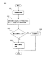
上記の組電池の製造方法の一実施形態に含まれる工程を示すフローチャートを図7に示す。まず、図6(a)に示したように、複数の固体電池100の受圧部120が固体電池の積層方向に沿って互いに間隔を開けて直列に並んで配置されるように、複数の固体電池100を積層する(ステップS101)。次に、ステップS101により得られた固体電池の積層体を積層方向に所定の圧力まで加圧装置により加圧するとともに、所定の圧力に達するまで、複数の固体電池の受圧部を介して加圧プレート間が通電したか否かを監視する(ステップS102)。所定の圧力に達するまでに加圧プレート間が通電したことを所定の時間検知した場合には異常と判断し、通電を検知しなかった場合には加圧が正常に行われたと判断する(ステップS103)。ステップS103において通電を検知しなかった場合、加圧された複数の固体電池の積層体を、例えば、適切な拘束装置により加圧したまま拘束して組電池を提供することができる(ステップS104)。ステップS103において通電を検知した場合、加圧装置を非常停止するか、又は通電が検知されないレベルまで加圧力を強制的に減少させる(ステップS105)。ステップS105において、複数の固体電池の積層体を加圧することを停止するか、又は通電が検知されないレベルまで加圧力を減少させた後、加圧プレート間から複数の固体電池の積層体を取り出し、加圧プレート間に新たに複数の固体電池を積層することで、組電池の製造を再開することができる。ステップS103において通電を検知した場合に、加圧プレート間から取り出された複数の固体電池は、各固体電池について個別に破損しているか否かを検査することにより再使用できるか否か判定することができる。
FIG. 7 is a flowchart showing steps included in an embodiment of the method for manufacturing the assembled battery. First, as shown in FIG. 6 (a), the plurality of solid state batteries are arranged such that the
本発明の上記の実施形態の組電池と組電池を構成する複数の固体電池の積層方向に組電池を加圧するための加圧装置と、組電池を構成する複数の固体電池が積層方向に加圧されることにより圧縮されたことに応じて複数の固体電池の複数の受圧部が互いに接触したことを積層方向における複数の受圧部の通電により検知するための通電検知装置とを含む蓄電装置を搭載した車両の走行制御のフローチャートを図8に示す。なお、本発明の組電池を加圧する方向は、当該組電池を構成する複数の固体電池の積層方向である。本発明の組電池とそれを加圧するための加圧装置を搭載した車両では、車両の走行状態及び組電池の充電状態に応じて、組電池の放電電流を、組電池に加える圧力を調整することにより制御できる。組電池に加える圧力の上限値は、組電池が破損するおそれのない値に設定することができる。この上限値を所定の圧力として、この上限値以下の圧力で組電池を加圧することができる。さらに、かかる車両では、図7の実施形態に関して説明したように、複数の固体電池の受圧部を介して加圧プレート間が通電したか否かを監視することによって、上記の組電池に加わる圧力が、例えば制御システムの故障により組電池が破損するおそれがあるレベルを超える過剰に高い圧力まで増加することを防止することができる。図8において、ステップS201は、車両の走行を開始するステップである。ステップS202は、例えば制御システムの故障により組電池が破損するおそれがあるレベルを超える過剰に高いレベルまで圧力が増加した結果、複数の固体電池の受圧部を介して加圧プレート間が通電したか否かを監視するステップである。所定の圧力に達するまでに加圧プレート間が通電したことを所定の時間検知した場合には異常と判断し、通電を検知しなかった場合には加圧が正常に行われたと判断する(ステップS203)。ステップS203において通電を所定の時間検知しなかった場合、車両の運転を継続する(ステップS204)。ステップS203において通電を検知した場合、通電が検知されないレベルまで組電池への加圧力を強制的に減少させて車両を停止する(ステップS205)。ステップS203において通電を検知した場合に、制御システムを修復し、また、組電池についても破損しているか否かを検査することにより再使用できるか否か判定することができる。 The pressurization device for pressurizing the assembled battery in the stacking direction of the assembled battery and the plurality of solid batteries constituting the assembled battery of the above embodiment of the present invention, and the plurality of solid batteries constituting the assembled battery are added in the stacking direction. A power storage device including an energization detection device for detecting, by energization of the plurality of pressure receiving portions in the stacking direction, that the plurality of pressure receiving portions of the plurality of solid state batteries are in contact with each other in response to being compressed by being pressed FIG. 8 shows a flowchart of the travel control of the mounted vehicle. In addition, the direction which pressurizes the assembled battery of this invention is a lamination direction of the some solid battery which comprises the said assembled battery. In a vehicle equipped with the assembled battery of the present invention and a pressure device for pressurizing the assembled battery, the pressure applied to the assembled battery by adjusting the discharge current of the assembled battery is adjusted according to the running state of the vehicle and the charged state of the assembled battery. Can be controlled. The upper limit value of the pressure applied to the assembled battery can be set to a value that does not cause the assembled battery to be damaged. With this upper limit as a predetermined pressure, the assembled battery can be pressurized at a pressure equal to or lower than the upper limit. Furthermore, in such a vehicle, as described with reference to the embodiment of FIG. 7, the pressure applied to the assembled battery is monitored by monitoring whether or not the pressure plates are energized via the pressure receiving portions of the plurality of solid state batteries. However, for example, it is possible to prevent the battery pack from increasing to an excessively high pressure exceeding a level at which the assembled battery may be damaged due to a failure of the control system. In FIG. 8, step S201 is a step of starting the running of the vehicle. In step S202, for example, whether the pressure plates are energized through the pressure receiving portions of the plurality of solid state batteries as a result of the pressure increasing to an excessively high level exceeding the level at which the assembled battery may be damaged due to a failure of the control system. This is a step for monitoring whether or not. If it is detected for a predetermined time that the pressure plate has been energized until the predetermined pressure is reached, it is determined to be abnormal, and if no current is detected, it is determined that pressurization has been normally performed (step). S203). If energization is not detected for a predetermined time in step S203, the vehicle continues to operate (step S204). When energization is detected in step S203, the vehicle is stopped by forcibly reducing the pressure applied to the assembled battery to a level where energization is not detected (step S205). When energization is detected in step S203, it is possible to determine whether or not the control system can be reused by repairing the control system and checking whether or not the assembled battery is also damaged.
以上、本発明の実施形態を、図面を参照して説明したが、これらの実施形態は例示のためのものであり、本発明は図面に示した実施形態に限定されない。 As mentioned above, although embodiment of this invention was described with reference to drawings, these embodiment is for illustration and this invention is not limited to embodiment shown on drawing.
本発明の固体電池及び組電池は、高い容量及び出力密度を有することに加えて、信頼性、耐久性などの性能特性に優れ、ハイブリッド自動車、電気自動車などの車両に搭載されるモーター用の電源として有用である。 The solid battery and the assembled battery of the present invention have a high capacity and output density, as well as excellent performance characteristics such as reliability and durability, and a power source for a motor mounted on a vehicle such as a hybrid vehicle or an electric vehicle. Useful as.
100 固体電池
110 外装体
112 外装体の周縁部の封止領域
120 受圧部
130、130A、130B 積層体
140 単電池
141 正極層
142 負極層
143 固体電解質層
144、144a〜d 集電体
150 積層部
410 第1の上型
420 第2の上型
430 下型
311、312 加圧プレート
320、330 成形装置
321、331 上型枠
322、332 下型枠
323、333 上側加圧プレート
324、334 下側加圧プレート
325、335 キャビティ
326、336 供給装置
327、337 注入路
328、338 接合部
329、339 導入口
DESCRIPTION OF
Claims (9)
前記積層体を収容する外装体、
を含む固体電池であって、前記固体電池は、さらに、前記外装体の周縁部の少なくとも一部に設けられた受圧部を含み、
前記受圧部が、前記単電池の積層方向に前記積層体を前記固体電池の使用時における許容最大圧力で加圧したときの前記積層体と前記外装体が互いに接している部分での前記積層体と前記外装体の合計厚みに等しい厚みを有し、
前記外装体は、樹脂層と金属箔と熱融着性樹脂層とが積層されたものであるヒートシール可能なラミネートフィルムから構成され、前記積層体は前記ヒートシール可能なラミネートフィルムに挟まれており、
前記外装体の周縁部において、前記ヒートシール可能なラミネートフィルムは封止されており、
前記受圧部は、前記外装体の周縁部の前記少なくとも一部を挟持していることを特徴とする固体電池。 A laminate including at least one unit cell including a positive electrode layer including a positive electrode active material, a negative electrode layer including a negative electrode active material, and a solid electrolyte layer stacked between the positive electrode layer and the negative electrode layer;
An exterior body that houses the laminate,
The solid battery further includes a pressure receiving portion provided on at least a part of a peripheral portion of the exterior body,
The laminated body at a portion where the laminated body and the exterior body are in contact with each other when the pressure receiving part pressurizes the laminated body at an allowable maximum pressure when the solid battery is used in the stacking direction of the unit cells. And having a thickness equal to the total thickness of the exterior body,
The exterior body is composed of a heat-sealable laminate film in which a resin layer, a metal foil, and a heat-fusible resin layer are laminated, and the laminate is sandwiched between the heat-sealable laminate films. And
In the periphery of the exterior body, the heat-sealable laminate film is sealed,
The solid pressure battery , wherein the pressure receiving portion sandwiches at least a part of a peripheral edge portion of the exterior body .
(a)正極活物質を含む正極層と、負極活物質を含む負極層と、前記正極層と前記負極層の間に積層された固体電解質層とを含む単電池を少なくとも1つ含む積層体を形成する工程;
(b)前記積層体を前記外装体に収容する工程;及び
(c)前記外装体の周縁部の少なくとも一部に、前記単電池の積層方向に前記積層体を前記固体電池の使用時における許容最大圧力で加圧したときの前記積層体と前記外装体が互いに接している部分での前記積層体と前記外装体の合計厚みに等しい厚みを有する受圧部を形成する工程;
を含む方法。 It is a manufacturing method of the solid battery according to claim 1,
(A) A laminate including at least one unit cell including a positive electrode layer including a positive electrode active material, a negative electrode layer including a negative electrode active material, and a solid electrolyte layer stacked between the positive electrode layer and the negative electrode layer. Forming step;
(B) said laminate is accommodated in the outer body step; at least a portion of the periphery of and (c) said outer body, acceptable in use of the solid-state battery of the laminate in the laminating direction of the unit cells Forming a pressure receiving portion having a thickness equal to a total thickness of the laminate and the exterior body at a portion where the laminate and the exterior body are in contact with each other when pressurized at a maximum pressure ;
Including methods.
(i)正極活物質を含む正極層と、負極活物質を含む負極層と、前記正極層と負極層の間に積層された固体電解質層とを含む単電池を少なくとも1つ含む積層体と、
前記積層体を収容する外装体、
を含む固体電池であって、前記固体電池は、さらに、前記外装体の周縁部の少なくとも一部に設けられた受圧部を含み、前記受圧部が、前記単電池の積層方向に前記積層体を前記固体電池の使用時における許容最大圧力で加圧したときの前記積層体と前記外装体が互いに接している部分での前記積層体と前記外装体の合計厚みに等しい厚みを有する固体電池を複数用意する工程;
(ii)前記複数の固体電池を、当該複数の固体電池の受圧部が積層方向に沿って互いに間隔を開けて並んで配置されるように積層する工程、ここで、前記複数の固体電池の各々を構成する正極層と固体電解質層と負極層の積層方向と前記複数の固体電池の積層方向は同一である;及び
(iii)前記複数の固体電池を積層方向に加圧する工程;
を含み、
前記外装体は、樹脂層と金属箔と熱融着性樹脂層とが積層されたものであるヒートシール可能なラミネートフィルムから構成され、前記積層体は前記ヒートシール可能なラミネートフィルムに挟まれており、
前記外装体の周縁部において、前記ヒートシール可能なラミネートフィルムは封止されており、
前記受圧部は、前記外装体の周縁部の前記少なくとも一部を挟持している、方法。 A method for producing an assembled battery including a plurality of solid state batteries,
(I) a laminate including at least one unit cell including a positive electrode layer including a positive electrode active material, a negative electrode layer including a negative electrode active material, and a solid electrolyte layer stacked between the positive electrode layer and the negative electrode layer;
An exterior body that houses the laminate,
The solid battery further includes a pressure receiving portion provided on at least a part of a peripheral portion of the exterior body, and the pressure receiving portion extends the stacked body in the stacking direction of the unit cells. A plurality of solid batteries having a thickness equal to the total thickness of the laminate and the exterior body at a portion where the laminate and the exterior body are in contact with each other when pressurized at an allowable maximum pressure when the solid battery is used. Preparing step;
(Ii) laminating the plurality of solid state batteries so that the pressure receiving portions of the plurality of solid state batteries are arranged side by side along the lamination direction, wherein each of the plurality of solid state batteries The stacking direction of the positive electrode layer, the solid electrolyte layer, and the negative electrode layer constituting the same and the stacking direction of the plurality of solid batteries are the same; and
(Iii) pressing the plurality of solid state batteries in the stacking direction;
Including
The exterior body is composed of a heat-sealable laminate film in which a resin layer, a metal foil, and a heat-fusible resin layer are laminated, and the laminate is sandwiched between the heat-sealable laminate films. And
In the periphery of the exterior body, the heat-sealable laminate film is sealed,
The pressure receiving part is a method of sandwiching at least a part of a peripheral part of the exterior body .
組電池を構成する複数の固体電池の積層方向に組電池を加圧するための加圧装置と、A pressurizing device for pressurizing the assembled battery in the stacking direction of a plurality of solid state batteries constituting the assembled battery;
組電池を構成する複数の固体電池が積層方向に加圧されることにより圧縮されたことに応じて複数の固体電池の複数の受圧部が互いに接触したことを積層方向における複数の受圧部の通電により検知するための通電検知装置と、Energization of the plurality of pressure-receiving portions in the stacking direction indicates that the plurality of pressure-receiving portions of the plurality of solid-state batteries are in contact with each other in response to the compression of the plurality of solid-state batteries constituting the assembled battery in the stacking direction. An energization detection device for detecting by,
を含み、前記複数の固体電池の受圧部がそれぞれ導電性を有する、蓄電装置。And the pressure receiving portions of the plurality of solid state batteries each have conductivity.
Priority Applications (3)
| Application Number | Priority Date | Filing Date | Title |
|---|---|---|---|
| JP2014055299A JP6032233B2 (en) | 2014-03-18 | 2014-03-18 | Solid battery and manufacturing method thereof, and assembled battery and manufacturing method thereof |
| US14/661,541 US9786946B2 (en) | 2014-03-18 | 2015-03-18 | Solid-state battery and method for producing the same, and assembled battery and method for producing the same |
| CN201510118039.8A CN104934649B (en) | 2014-03-18 | 2015-03-18 | Solid state battery and its manufacture method and Battery pack and its manufacture method |
Applications Claiming Priority (1)
| Application Number | Priority Date | Filing Date | Title |
|---|---|---|---|
| JP2014055299A JP6032233B2 (en) | 2014-03-18 | 2014-03-18 | Solid battery and manufacturing method thereof, and assembled battery and manufacturing method thereof |
Publications (2)
| Publication Number | Publication Date |
|---|---|
| JP2015179566A JP2015179566A (en) | 2015-10-08 |
| JP6032233B2 true JP6032233B2 (en) | 2016-11-24 |
Family
ID=54121706
Family Applications (1)
| Application Number | Title | Priority Date | Filing Date |
|---|---|---|---|
| JP2014055299A Active JP6032233B2 (en) | 2014-03-18 | 2014-03-18 | Solid battery and manufacturing method thereof, and assembled battery and manufacturing method thereof |
Country Status (3)
| Country | Link |
|---|---|
| US (1) | US9786946B2 (en) |
| JP (1) | JP6032233B2 (en) |
| CN (1) | CN104934649B (en) |
Families Citing this family (14)
| Publication number | Priority date | Publication date | Assignee | Title |
|---|---|---|---|---|
| JP6641814B2 (en) | 2015-09-11 | 2020-02-05 | 住友電気工業株式会社 | Silicon carbide epitaxial substrate and method for manufacturing silicon carbide semiconductor device |
| KR101836581B1 (en) * | 2015-12-10 | 2018-03-08 | 현대자동차주식회사 | A solid-state battery and preparation thereof |
| JP6607959B2 (en) * | 2015-12-16 | 2019-11-20 | 富士フイルム株式会社 | Electrode material, electrode sheet for all-solid-state secondary battery, all-solid-state secondary battery, electrode sheet for all-solid-state secondary battery, and method for producing all-solid-state secondary battery |
| TWI638475B (en) * | 2016-08-02 | 2018-10-11 | 財團法人工業技術研究院 | Sulfur doped oxide solid electrolyte powder and solid state battery containing the same |
| JP6673249B2 (en) * | 2017-02-14 | 2020-03-25 | トヨタ自動車株式会社 | Manufacturing method of laminated all solid state battery |
| JP6839264B2 (en) * | 2017-03-08 | 2021-03-03 | 富士フイルム株式会社 | A method for producing a solid electrolyte-containing sheet, a solid electrolyte composition and an all-solid-state secondary battery, and a solid electrolyte-containing sheet and an all-solid-state secondary battery. |
| JP6943699B2 (en) * | 2017-09-14 | 2021-10-06 | 株式会社エンビジョンAescジャパン | Stacked batteries and battery modules |
| US11264641B2 (en) | 2018-01-10 | 2022-03-01 | Samsung Electronics Co., Ltd. | All-solid secondary battery, multilayered all-solid secondary battery, and method of manufacturing all-solid secondary battery |
| JP7085390B2 (en) * | 2018-04-09 | 2022-06-16 | 日産自動車株式会社 | Battery manufacturing method |
| JP6916151B2 (en) * | 2018-06-26 | 2021-08-11 | トヨタ自動車株式会社 | Manufacturing method of all-solid-state battery |
| KR20210071023A (en) * | 2018-10-02 | 2021-06-15 | 퀀텀스케이프 배터리, 인코포레이티드 | Methods of Making and Using Electrochemical Cells Comprising Interlayers |
| JP7221019B2 (en) * | 2018-10-15 | 2023-02-13 | 現代自動車株式会社 | Method for manufacturing all-solid-state battery |
| JP2021190282A (en) * | 2020-05-29 | 2021-12-13 | 本田技研工業株式会社 | Solid-state battery module and solid-state battery cell |
| JP2022000840A (en) * | 2020-06-19 | 2022-01-04 | トヨタ自動車株式会社 | Stacked battery |
Family Cites Families (15)
| Publication number | Priority date | Publication date | Assignee | Title |
|---|---|---|---|---|
| US6558438B1 (en) * | 1999-07-23 | 2003-05-06 | Nec Corporation | Method for producing a pressurized package for a film packed battery |
| JP3533117B2 (en) * | 1999-07-23 | 2004-05-31 | 日本電気株式会社 | Method of manufacturing film-covered battery |
| JP3594023B2 (en) * | 2002-07-30 | 2004-11-24 | 日産自動車株式会社 | Battery module |
| JP4687052B2 (en) * | 2004-09-29 | 2011-05-25 | トヨタ自動車株式会社 | Sheet material type battery manufacturing method and sheet material type battery |
| KR100870846B1 (en) * | 2005-01-04 | 2008-11-27 | 닛본 덴끼 가부시끼가이샤 | Case for film-packed electrical device and film-packed electrical device assembly |
| JP2006313655A (en) * | 2005-05-06 | 2006-11-16 | Ngk Spark Plug Co Ltd | Thin battery |
| US20080057390A1 (en) * | 2006-08-31 | 2008-03-06 | Seiko Epson Corporation | Secondary battery |
| JP4501080B2 (en) * | 2006-10-23 | 2010-07-14 | トヨタ自動車株式会社 | Battery pack and manufacturing method thereof |
| JP2009252670A (en) * | 2008-04-10 | 2009-10-29 | Toyota Motor Corp | Method for manufacturing all-solid lithium secondary battery |
| JP5382130B2 (en) * | 2009-11-02 | 2014-01-08 | トヨタ自動車株式会社 | Method for producing solid electrolyte battery |
| JP2011100693A (en) * | 2009-11-09 | 2011-05-19 | Toyota Motor Corp | Current collector and laminated battery |
| JP5636965B2 (en) | 2011-01-05 | 2014-12-10 | トヨタ自動車株式会社 | Method for producing electrode body for lithium ion secondary battery and method for producing lithium ion secondary battery |
| JP2012222981A (en) | 2011-04-11 | 2012-11-12 | Toyota Motor Corp | Vehicle drive device |
| KR101371040B1 (en) * | 2011-06-16 | 2014-03-10 | 에스케이이노베이션 주식회사 | Pouch type secondary battery and methods for producing it |
| JP2013045556A (en) | 2011-08-23 | 2013-03-04 | Toyota Motor Corp | Secondary battery system |
-
2014
- 2014-03-18 JP JP2014055299A patent/JP6032233B2/en active Active
-
2015
- 2015-03-18 CN CN201510118039.8A patent/CN104934649B/en active Active
- 2015-03-18 US US14/661,541 patent/US9786946B2/en active Active
Also Published As
| Publication number | Publication date |
|---|---|
| CN104934649B (en) | 2018-01-02 |
| JP2015179566A (en) | 2015-10-08 |
| CN104934649A (en) | 2015-09-23 |
| US20150270585A1 (en) | 2015-09-24 |
| US9786946B2 (en) | 2017-10-10 |
Similar Documents
| Publication | Publication Date | Title |
|---|---|---|
| JP6032233B2 (en) | Solid battery and manufacturing method thereof, and assembled battery and manufacturing method thereof | |
| JP6673249B2 (en) | Manufacturing method of laminated all solid state battery | |
| EP2214247B1 (en) | Manufacturing method of bipolar cell and bipolar cell | |
| JP5365619B2 (en) | Bipolar battery | |
| JP5573954B2 (en) | Bipolar electrode, bipolar secondary battery using the same, and method of manufacturing bipolar electrode | |
| KR100987849B1 (en) | Bipolar battery and manufacturing method for the same | |
| JP2005183287A (en) | Method for manufacturing solid electrolyte battery | |
| JP4529516B2 (en) | Power supply | |
| WO2010047079A1 (en) | Multilayer lithium-ion secondary battery | |
| US20140248526A1 (en) | Galvanic element with enhanced safety properties | |
| WO2016132444A1 (en) | Lithium ion secondary battery production method and lithium ion secondary battery | |
| KR20030074219A (en) | Method for fabricating lithium ion seconda ry battery | |
| JP2006120577A (en) | Polymer battery | |
| JP2015128020A (en) | Bipolar secondary battery, bipolar secondary battery module, and method for manufacturing bipolar secondary battery | |
| JP2004253155A (en) | Bipolar battery | |
| JP2012038584A (en) | Battery and manufacturing method thereof | |
| JP4178926B2 (en) | Bipolar battery, bipolar battery manufacturing method, battery pack and vehicle | |
| JP5631537B2 (en) | Bipolar secondary battery | |
| US11876173B2 (en) | All-solid-state battery, method of producing battery element, and method of producing all-solid-state battery | |
| JP5343663B2 (en) | Method and apparatus for manufacturing bipolar secondary battery | |
| CN111819726A (en) | Stacking type electrode assembly for alleviating bending phenomenon and method for manufacturing the same | |
| JP2015032495A (en) | Manufacturing method of solid-state battery | |
| JP2006173000A (en) | Method for manufacturing lithium polymer battery and battery obtained by the same | |
| JP5375263B2 (en) | Battery manufacturing method and manufacturing apparatus | |
| WO2019189860A1 (en) | Secondary battery and manufacturing method therefor |
Legal Events
| Date | Code | Title | Description |
|---|---|---|---|
| A977 | Report on retrieval |
Free format text: JAPANESE INTERMEDIATE CODE: A971007 Effective date: 20160223 |
|
| A131 | Notification of reasons for refusal |
Free format text: JAPANESE INTERMEDIATE CODE: A131 Effective date: 20160308 |
|
| A601 | Written request for extension of time |
Free format text: JAPANESE INTERMEDIATE CODE: A601 Effective date: 20160506 |
|
| A521 | Request for written amendment filed |
Free format text: JAPANESE INTERMEDIATE CODE: A523 Effective date: 20160526 |
|
| TRDD | Decision of grant or rejection written | ||
| A01 | Written decision to grant a patent or to grant a registration (utility model) |
Free format text: JAPANESE INTERMEDIATE CODE: A01 Effective date: 20160927 |
|
| A61 | First payment of annual fees (during grant procedure) |
Free format text: JAPANESE INTERMEDIATE CODE: A61 Effective date: 20161010 |
|
| R151 | Written notification of patent or utility model registration |
Ref document number: 6032233 Country of ref document: JP Free format text: JAPANESE INTERMEDIATE CODE: R151 |