JP6030833B2 - X-ray inspection equipment - Google Patents
X-ray inspection equipment Download PDFInfo
- Publication number
- JP6030833B2 JP6030833B2 JP2011273791A JP2011273791A JP6030833B2 JP 6030833 B2 JP6030833 B2 JP 6030833B2 JP 2011273791 A JP2011273791 A JP 2011273791A JP 2011273791 A JP2011273791 A JP 2011273791A JP 6030833 B2 JP6030833 B2 JP 6030833B2
- Authority
- JP
- Japan
- Prior art keywords
- ray
- inspection
- substrate
- optical
- camera
- Prior art date
- Legal status (The legal status is an assumption and is not a legal conclusion. Google has not performed a legal analysis and makes no representation as to the accuracy of the status listed.)
- Active
Links
Images

Landscapes
- Analysing Materials By The Use Of Radiation (AREA)
Description
本発明は、X線検査装置に関し、特に、光学撮像部を備えたX線検査装置に関する。 The present invention relates to an X-ray inspection apparatus, and more particularly to an X-ray inspection apparatus provided with an optical imaging unit.
従来、光学撮像部を備えたX線検査装置が知られている(たとえば、特許文献1参照)。 Conventionally, an X-ray inspection apparatus including an optical imaging unit is known (for example, see Patent Document 1).
上記特許文献1には、可視光が照射される基板(検査対象物)を撮像する可視光撮像部(光学撮像部)と、X線源から照射されて基板を透過したX線を撮像するX線撮像部とを備えた基板検査装置(X線検査装置)が開示されている。このX線撮像部は、可視光撮像部により撮像される側から見て基板の後方(下方)に配置されており、可視光撮像部による撮像と同一視野でX線撮像を行うことが可能に構成されている。
In
しかしながら、上記特許文献1の基板検査装置(X線検査装置)では、X線撮像部が可視光撮像部により撮像される側から見て基板の後方(下方)に配置されているので、可視光撮像部により貫通孔を有する基板を撮像する場合に、貫通孔を介して基板の後方のX線撮像部が写り込んでしまい、その結果、基板の貫通孔を精度よく識別することができない場合があるという不都合がある。このため、上記特許文献1の基板検査装置(X線検査装置)では、基板(検査対象物)の状態を精度よく検査することができない場合があるという問題点がある。
However, in the substrate inspection apparatus (X-ray inspection apparatus) of
この発明は、上記のような課題を解決するためになされたものであり、この発明の1つの目的は、検査対象物の状態を精度よく検査することが可能なX線検査装置を提供することである。 The present invention has been made to solve the above-described problems, and an object of the present invention is to provide an X-ray inspection apparatus capable of inspecting the state of an inspection object with high accuracy. It is.
上記目的を達成するために、この発明の一の局面におけるX線検査装置は、可視光が照射される検査対象物を撮像する光学撮像部と、光学撮像部による撮像結果に基づいて検査対象物の状態を検査する光学検査部と、光学撮像部により撮像される側から見て検査対象物の後方に配置される背景部材と、検査対象物を境として光学撮像部と同じ側に配置され、検査対象物にX線を照射するX線源と、検査対象物を境としてX線源と反対側に配置され、X線源により照射されて検査対象物を透過したX線を撮像するX線撮像部とを備え、背景部材は、X線撮像部とは別体で、かつ、X線源から照射されるX線を透過可能な素材により構成され、光学撮像部により撮像される側から見て検査対象物の後方でかつX線撮像部の前方に配置されるとともに、光学検査部により検査対象物との識別が可能な表面色を有している。 In order to achieve the above object, an X-ray inspection apparatus according to one aspect of the present invention includes an optical imaging unit that images an inspection target irradiated with visible light, and an inspection target based on an imaging result of the optical imaging unit. An optical inspection unit that inspects the state of the above, a background member that is arranged behind the inspection object as viewed from the side imaged by the optical imaging unit, and an optical imaging unit that is disposed on the same side as the inspection object, An X-ray source that irradiates the inspection object with X-rays and an X-ray that is disposed on the opposite side of the X-ray source with the inspection object as a boundary, and that images the X-rays that are irradiated by the X-ray source and transmitted through the inspection object The background member is made of a material that is separate from the X-ray imaging unit and can transmit X-rays emitted from the X-ray source, and is viewed from the side imaged by the optical imaging unit. Arranged behind the inspection object and in front of the X-ray imaging unit. Furthermore, it has a surface color that can be distinguished from the inspection object by the optical inspection unit.
この発明の一の局面によるX線検査装置では、上記のように、光学撮像部により撮像される側から見て検査対象物の後方に配置される背景部材を、光学検査部により検査対象物との識別が可能な表面色を有するように構成することによって、光学撮像部により貫通孔を有する検査対象物を撮像する場合に、検査対象物との識別が可能な上記表面色を有する背景部材が検査対象物の貫通孔を介して写り込むので、光学検査部により、上記表面色を有する背景部材が写り込んだ部分を検査対象物に形成された貫通孔として精度よく識別することができる。これにより、検査対象物の状態を精度よく検査することができる。また、光学撮像部により検査対象物を光学撮像する際に、検査対象物の貫通孔を介してX線撮像部ではなく背景部材を写り込ませることができるので、X線撮像部の表面色に関わらず、背景部材が写り込んだ部分を検査対象物に形成された貫通孔として精度よく識別することができる。また、X線源から照射されるX線を透過可能な素材により背景部材を構成することによって、背景部材が平面視でX線撮像部による撮像視野内に位置する場合でも、X線撮像部により検査対象物をX線撮像することができるので、光学撮像部による光学撮像とX線撮像部によるX線撮像とを互いに並行して行うことができる。 In the X-ray inspection apparatus according to one aspect of the present invention, as described above, the background member arranged behind the inspection object as viewed from the side imaged by the optical imaging unit is used as the inspection object by the optical inspection unit. The background member having the surface color that can be distinguished from the inspection object when the inspection object having the through hole is imaged by the optical imaging unit. Since the image is reflected through the through hole of the inspection object, the portion where the background member having the surface color is reflected can be accurately identified as the through hole formed in the inspection object by the optical inspection unit. Thereby, the state of the inspection object can be inspected with high accuracy. In addition, when the optical imaging unit optically images the inspection object, the background member can be reflected instead of the X-ray imaging unit through the through hole of the inspection object, so that the surface color of the X-ray imaging unit can be reflected. Regardless, the portion in which the background member is reflected can be accurately identified as a through-hole formed in the inspection object. In addition, by configuring the background member with a material that can transmit X-rays emitted from the X-ray source, even when the background member is located in the imaging field of view by the X-ray imaging unit in plan view, the X-ray imaging unit Since the inspection object can be X-ray imaged, optical imaging by the optical imaging unit and X-ray imaging by the X-ray imaging unit can be performed in parallel with each other.
上記一の局面によるX線検査装置において、好ましくは、背景部材は、検査対象物に対して光学検査部により検査対象物との識別が可能な階調または輝度の表面色を有している。このように構成すれば、光学検査部により、貫通孔を介して写り込む背景部材と検査対象物とを、それぞれの階調または輝度に基づいて容易に識別することができる。 In X-ray inspecting apparatus according to the first aspect, preferably, the background member has a surface color of possible gradation or luminance identifying the test object by the optical inspection unit relative to test object. If comprised in this way, the background member and inspection object which are reflected via a through-hole by an optical inspection part can be easily identified based on each gradation or brightness | luminance.
上記一の局面によるX線検査装置において、好ましくは、X線撮像部は、光学撮像部が検査対象物を光学撮像する際に並行して検査対象物をX線撮像可能なように構成されている。このように構成すれば、光学撮像部による光学撮像とX線撮像部によるX線撮像とを互いに並行して行うことができるので、光学撮像とX線撮像とを互いにずらして異なる時間に行う場合とは異なり、光学撮像とX線撮像との両方を含む撮像動作をより短時間で行うことができる。これにより、X線検査装置による検査作業時間を短縮することができる。 In X-ray inspecting apparatus according to the aforementioned aspect preferably, the X-ray imaging unit is configured to test object in parallel when the optical imaging unit is optically imaging an inspection object so as to allow X-ray imaging Yes. With this configuration, optical imaging by the optical imaging unit and X-ray imaging by the X-ray imaging unit can be performed in parallel with each other, so that optical imaging and X-ray imaging are performed at different times while being shifted from each other. Unlike the above, an imaging operation including both optical imaging and X-ray imaging can be performed in a shorter time. Thereby, the inspection work time by the X-ray inspection apparatus can be shortened.
上記一の局面によるX線検査装置において、好ましくは、検査対象物は、貫通孔が形成された基板を含み、背景部材は、光学撮像部により撮像される側から見て、表面色を有する領域が基板の貫通孔を介して露出されるように構成されている。このように構成すれば、光学撮像部による光学撮像により、背景部材の上記表面色を有する領域が検査対象物の貫通孔を介して写り込むので、光学検査部により、背景部材の上記表面色を有する領域が写り込んだ部分を検査対象物の貫通孔として容易に識別することができる。
In X-ray inspecting apparatus according to the aforementioned aspect, the area preferably inspected object comprises a substrate having a through hole formed, the background member, when viewed from the side to be imaged by the optical imaging unit, having a surface color Is exposed through the through hole of the substrate. If comprised in this way, since the area | region which has the said surface color of a background member will be reflected through the through-hole of a test object by the optical imaging by an optical imaging part, the said surface color of a background member will be reflected by the optical inspection part. The portion in which the region that is included can be easily identified as the through hole of the inspection object.
本発明によれば、上記のように、検査対象物の状態を精度よく検査することができる。 According to the present invention, as described above, the state of the inspection object can be accurately inspected.
以下、本発明の実施形態を図面に基づいて説明する。 Hereinafter, embodiments of the present invention will be described with reference to the drawings.
(第1実施形態)
図1〜図4を参照して、本発明の第1実施形態によるX線検査装置100の構成について説明する。
(First embodiment)
With reference to FIGS. 1-4, the structure of the
第1実施形態によるX線検査装置100は、図示しない電子部品が搭載された基板110において、基板110に対する電子部品の接続状態を主に検査するものである。また、X線検査装置100は、基板110に対する電子部品の接続状態を、X線撮像および光学撮像の両方の撮像結果に基づいて検査することが可能に構成されている。なお、基板110は、本発明の「検査対象物」の一例である。
The
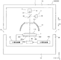
具体的には、X線検査装置100は、図1に示すように、X線検査装置100の各部を内部に収容するハウジング1(基台1A、側壁部材1B、および天井部材1Cとから構成される)と、XY駆動テーブル2と、光学撮像装置3と、X線撮像装置4と、コントローラ5(図2参照)とを備えている。X線検査装置100は、ハウジング1の側壁部材1Bに設けられた搬入口11から搬入された基板110に対して検査を行い、検査終了後に基板110を側壁部材1Bに設けられた搬出口12から搬出するように構成されている。
Specifically, as shown in FIG. 1, the
基台1A上に配置されるXY駆動テーブル2は、基板110の周辺部を支持する機能を有し、基板110の周辺部を支持する支持部の内側は、X線が邪魔されずに透過可能となるようにされている。また、XY駆動テーブル2は、水平面内のX方向およびY方向に移動可能に構成されている。また、XY駆動テーブル2は、サーボモータなどからなり基台1A上に固定されるXY駆動機構21により駆動されるように構成されている。具体的には、XY駆動テーブル2は、ハウジング1の搬入口11まで移動して基板110を受け取るように構成されている。また、XY駆動テーブル2は、受け取った基板110を所定の検査位置まで搬送して位置決めするように構成されている。また、XY駆動テーブル2は、検査済みの基板110をハウジング1の搬出口12まで搬送するように構成されている。また、XY駆動テーブル2により基板110を水平面内で移動させることによって、後述の光学カメラ33およびX線カメラ42による撮像視野を変えたり、後述のX線源41から照射されるX線の基板110への入射角度を変えたりすることが可能である。
The XY drive table 2 disposed on the
光学撮像装置3は、側壁部材1Bまたは天井部材1Cに支持され、図1に示すように、照明31と、ミラー32と、光学カメラ33とにより構成されている。照明31は、下方に向かって広がるドーム形状のカバー部材と、このカバー部材内側に配置され可視光を照射する複数のLEDを含んでいる。ドーム形状の照明31は、検査位置に位置する基板110を上方(Z1方向)から覆うように設けられており、基板110の上面(Z1方向側の表面)に可視光を照射するように構成されている。また、ドーム形状の照明31の天井部には、上下方向に貫通する開口311が形成されている。なお、光学カメラ33は、本発明の「光学撮像部」の一例である。
The
ミラー32は、照明31の上方で開口311に対応する位置に配置されている。これにより、ミラー32には、照明31の可視光により照らされた基板110が開口311を介して写される。また、ミラー32は、後述のX線源41から照射されたX線を透過可能に構成されている。光学カメラ33は、カラー画像に対応した光学CCD(Charge Coupled Device)カメラからなる。また、光学カメラ33は、ミラー32の近傍に配置されており、ミラー32に写された像を撮像するように構成されている。すなわち、光学カメラ33は、照明31により可視光が照射された基板110をミラー32を介して撮像するように構成されている。また、図3に示すように、光学カメラ33による撮像視野33aの中心は、後述のX線源41から照射されるX線の中心軸C1上に配置されている。また、撮像視野33aは、36mm×44mmの矩形視野である。
The
X線撮像装置4は、側壁部材1B、あるいは天井部材1Cに支持されたX線源41と、基台1A上に支持されたX線カメラ42とにより構成されている。X線源41は、基板110を境として光学カメラ33と同じ側(Z1方向側)で、かつ、ミラー32の上方に配置されている。また、X線源41は、基板110に対して開口311を通過してX線を照射可能に構成されている。また、X線源41は、中心軸C1を中心に下方に向かって放射状にX線を照射するように構成されている。X線カメラ42は、X線CCDカメラからなり、略直方体形状に形成されている。また、X線カメラ42は、基板110を境としてX線源41と反対側(Z2方向側)に配置されている。具体的には、X線カメラ42は、基板110の下方(Z2方向)の基台1A上に配置されている。言い換えると、X線カメラ42は、光学カメラ33により撮像される側(Z1方向側)から見て基板110の後方(Z2方向)に配置されている。また、X線カメラ42は、X線源41により照射されて開口311を通過し基板110を透過したX線を撮像するように構成されている。なお、X線カメラ42は、本発明の「X線撮像部」および「背景部材」の一例である。
The X-ray imaging apparatus 4 includes an
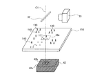
また、X線カメラ42は、基台1A上において水平面内のX方向およびY方向に移動可能であり、基板110に沿う方向にX線源41に対して相対移動可能に構成されている。また、X線カメラ42は、水平面内で移動することにより、傾斜した方向から基板110に入射したX線を検知することが可能である。すなわち、X線カメラ42により、X線斜視画像を撮像することが可能である。また、X線カメラ42は、サーボモータなどからなり基台1A上に固定されるXY駆動機構422により駆動されるように構成されている。また、X線カメラ42は、光学カメラ33により基板110が光学撮像される際に、X線の中心軸C1上に配置されるように構成されている。詳細には、X線カメラ42は、図3に示すように、光学カメラ33により基板110が光学撮像される際に、光学カメラ33による撮像視野33a内に移動されるように構成されている。また、X線カメラ42は、光学カメラ33が基板110を光学撮像する際に並行して基板110をX線撮像することが可能に構成されている。また、X線カメラ42は、光学カメラ33による撮像視野33aと同軸の撮像視野でX線撮像することが可能に構成されている。
Further, the
また、X線カメラ42は、図3に示すように、光学カメラ33により撮像される側(Z1方向側)から見て、光学カメラ33による撮像視野33aよりも大きい面積を有するように形成されている。すなわち、X線カメラ42の上面(Z1方向の表面)42aは、光学カメラ33による撮像視野33aよりも大きい面積を有している。また、X線カメラ42は、外表面の全域にわたって黒色の表面色を有している。詳細には、X線カメラ42は、図示しない撮像素子が配置される素子設置領域42bも含む外表面の全域にわたって黒色の表面色を有している。また、図4に示すように、黒色の表面色を有するX線カメラ42は、光学カメラ33により撮像される側から見て、基板110に形成されたスルーホール111を介して露出されるように構成されている。これにより、X線カメラ42は、スルーホール111を介して光学カメラ33による光学撮像画像に写り込む。なお、X線カメラ42の黒色の表面色については以下で詳細に説明する。また、スルーホール111は、本発明の「貫通孔」の一例である。
Further, as shown in FIG. 3, the
コントローラ5は、光学撮像装置3およびX線撮像装置4からそれぞれ光学撮像結果およびX線撮像結果を取得するように構成されている。そして、コントローラ5は、取得した光学撮像結果およびX線撮像結果に基づいて、基板110に対する電子部品の接続状態(たとえば、半田の塗布状態など)を確認する機能を有している。また、コントローラ5は、図2に示すように、コントローラ5により実行される制御動作を統括的に管理するCPU51と、モータ制御部52と、画像処理部53と、検査判定処理部54とを含んでいる。なお、検査判定処理部54は、本発明の「光学検査部」の一例である。
The
モータ制御部52は、XY駆動テーブル2のXY駆動機構21およびX線カメラ42のXY駆動機構422を制御するように構成されている。画像処理部53は、検査判定処理部54により判定可能なように、光学撮像装置3およびX線撮像装置4からそれぞれ取得した光学撮像結果(光学撮像画像)およびX線撮像結果(X線撮像画像)に対して所定の画像処理を行うように構成されている。
The
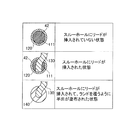
検査判定処理部54は、画像処理部53により画像処理された光学撮像画像およびX線撮像画像に基づいて、基板110に対する電子部品の接続状態の良否を判定(検査)する機能を有している。具体的には、検査判定処理部54は、光学撮像画像に基づいて、電子部品の接続状態の外観検査としての良否を判定するように構成されている。検査判定処理部54は、光学撮像画像の色情報に基づいて、電子部品の接続状態の外観検査としての良否を判定する。詳細には、検査判定処理部54は、画像処理部53により画像処理された光学撮像画像に基づいて、各画素の色をR(赤)G(緑)B(青)に分割して、RGBそれぞれの階調を算出するように構成されている。そして、検査判定処理部54は、RGBそれぞれの階調に基づいて、撮像されたものを特定して接続状態の良否を判定する。具体的には、図4に示すように、検査判定処理部54は、RGBそれぞれの階調に基づいて、少なくとも、基板110に設けられたランド120、電子部品のリード130および半田140を互いに識別可能に構成されている。
The inspection
次に、第1実施形態におけるX線カメラ42の表面色について説明する。第1実施形態では、X線カメラ42は、上記のとおり、外表面の全域にわたって黒色の表面色を有している。具体的には、X線カメラ42の表面色は、検査判定処理部54により、基板110(緑色)、ランド120(銅色)、リード130(銀色)および半田140(銀色)との識別が可能な階調を有する黒色である。
Next, the surface color of the
ここで、図4に示すように、基板110に形成されたスルーホール111にリード130が挿入されていない場合、および、スルーホール111にリード130が挿入された状態で半田が塗布されていない場合には、基板110は、スルーホール111を介して黒色の表面色を有するX線カメラ42が露出された状態で光学カメラ33により光学撮像される。この際、スルーホール111を介して露出されたX線カメラ42の黒色の表面色が基板110、ランド120、リード130および半田140との識別が可能な階調を有しているため、検査判定処理部54により、基板110、ランド120、リード130および半田140に対してスルーホール111を精度よく識別することが可能である。そして、スルーホール111が確認された場合は、スルーホール111に半田140が充填されていない状態を示しており、検査判定処理部54は、外観検査結果として、基板110に対する電子部品の接続状態が不良であると判定する。一方、検査判定処理部54は、図4に示すように、ランド120およびスルーホール111の全体が半田140により覆われている場合には、外観検査結果として、基板110に対する電子部品の接続状態が良好であると判定するように構成されている。なお、ランド120およびスルーホール111の全体が半田140により覆われていても、リード130が識別できない場合、スルーホール111に挿入されたリード130および充填された半田140が識別されても、充填された半田140に所定以上の大きさの貫通孔が識別される場合、さらには、リード130が挿入されないで半田140が充填される基板110の表裏導通用のスルーホール111では、充填された半田140に所定以上の大きさの貫通孔が識別される場合、検査判定処理部54は、外観検査結果として、基板110に対する電子部品の接続状態が不良であると判定する。
Here, as shown in FIG. 4, when the
また、検査判定処理部54は、X線撮像画像に基づいて、電子部品の接続状態の内部検査としての良否を判定するように構成されている。具体的には、検査判定処理部54は、X線撮像画像から得られる断層画像に基づいて、塗布された半田の内部を確認して良否を判定する。このように検査判定処理部54は、光学撮像画像に基づく外観検査に加えて、X線撮像画像に基づく内部検査も行うことが可能である。
Further, the inspection
また、コントローラ5は、モデリング演算処理部55と、配置情報記憶部56とを含んでいる。モデリング演算処理部55は、断層画像を構成する複数枚のX線撮像画像の撮像条件(撮像角度など)を演算により求める機能を有している。配置情報記憶部56は、基板110に搭載される電子部品等の配置情報(形状や寸法、配置位置などの情報)を記憶する機能を有している。モデリング演算処理部55は、配置情報記憶部56に記憶された配置情報に基づいて、撮像条件を求めるように構成されている。
The
第1実施形態では、上記のように、光学カメラ33により撮像される側(Z1方向側)から見て基板110の後方に配置されたX線カメラ42を、検査判定処理部54により基板110との識別が可能な表面色(黒色)を有するように構成することによって、光学カメラ33によりスルーホール111を有する基板110を撮像する場合に、基板110との識別が可能な上記表面色(黒色)を有するX線カメラ42が基板110のスルーホール111を介して写り込むので、検査判定処理部54により、上記表面色(黒色)を有するX線カメラ42が写り込んだ部分を基板110に形成されたスルーホール111として精度よく識別することができる。これにより、基板110の状態を精度よく検査することができる。
In the first embodiment, as described above, the
また、第1実施形態では、光学カメラ33により撮像される側(Z1方向側)から見て光学カメラ33による撮像視野33aよりも大きい領域において上記表面色(黒色)を有するようにX線カメラ42を構成する。これにより、光学カメラ33による撮像視野33aの全域にわたって、スルーホール111を介してX線カメラ42の上記表面色(黒色)を有する領域を写り込ませることができるので、光学カメラ33による撮像視野33aの全域にわたって基板110のスルーホール111を精度よく識別することができる。
In the first embodiment, the
また、第1実施形態では、光学カメラ33により基板110を光学撮像する際に、光学カメラ33による撮像視野33a内に移動されるようにX線カメラ42を構成する。これにより、光学カメラ33により基板110を光学撮像する際に、光学カメラ33による撮像視野33a内で平面視で基板110の後方に重なるようにX線カメラ42が移動されるので、上記表面色(黒色)を有するX線カメラ42を基板110のスルーホール111を介して確実に写り込ませることができる。
In the first embodiment, the
また、第1実施形態では、X線カメラ42を、基板110に対して検査判定処理部54により基板110との識別が可能な階調の表面色(黒色)を有するように構成する。これにより、検査判定処理部54により、スルーホール111を介して写り込むX線カメラ42と基板110とを、それぞれの階調に基づいて容易に識別することができる。
In the first embodiment, the
また、第1実施形態では、光学カメラ33が基板110を光学撮像する際に、並行して基板110をX線撮像可能なようにX線カメラ42を構成する。これにより、光学カメラ33による光学撮像とX線カメラ42によるX線撮像とを互いに並行して行うことができるので、光学撮像とX線撮像とを互いにずらして異なる時間に行う場合とは異なり、光学撮像とX線撮像との両方を含む撮像動作をより短時間で行うことができる。これにより、X線検査装置100による検査作業時間を短縮することができる。
In the first embodiment, when the
また、第1実施形態では、光学カメラ33により撮像される側(Z1方向側)から見て、上記表面色(黒色)を有する領域が基板のスルーホール111を介して露出されるようにX線カメラ42を構成する。これにより、光学カメラ33による光学撮像により、X線カメラ42の上記表面色(黒色)を有する領域が基板110のスルーホール111を介して写り込むので、検査判定処理部54により、X線カメラ42の上記表面色(黒色)を有する領域が写り込んだ部分を基板110のスルーホール111として容易に識別することができる。
In the first embodiment, the X-ray is so exposed that the region having the surface color (black) is exposed through the through-
(第2実施形態)
次に、図1を参照して、本発明の第2実施形態によるX線検査装置200について説明する。この第2実施形態では、上記第1実施形態と異なり、基板110とX線カメラ42との間に黒色の表面色を有する背景部材201(図1において2点鎖線で表示)を備えた構成について説明する。
(Second Embodiment)
Next, an
第2実施形態によるX線検査装置200は、光学カメラ33により撮像される側から見て、基板110の後方(Z2方向)でかつX線カメラ42の前方(Z1方向)に配置される背景部材201を備えている。背景部材201は、X線カメラ42とは別体である。また、背景部材201は、取付部材202を介してXY駆動テーブル2により支持されている。これにより、背景部材201は、基板110とともにXY駆動テーブル2の移動に連動して移動する。なお、XY駆動テーブル2は、本発明の「支持部」の一例である。
The
また、背景部材201は、平面視で略矩形形状を有する板状部材である。また、背景部材201は、基板110に平行に配置されている。また、背景部材201は、光学カメラ33により撮像される側から見て基板110よりも大きい面積の外形形状を有している。すなわち、背景部材201の上面(Z1方向の表面)201aは、平面視で基板110よりも大きい面積を有している。また、背景部材201の上面201aは、光学カメラ33による撮像視野33aよりも大きい面積を有している。
The
ここで、第2実施形態では、背景部材201は、外表面の全域にわたって黒色の表面色を有している。背景部材201の表面色は、検査判定処理部54により基板110、ランド120、リード130および半田140との識別が可能な階調を有する黒色である。また、背景部材201は、光学カメラ33により撮像される側から見て、基板110に形成されたスルーホール111(図4参照)を介して露出されるように構成されている。これにより、黒色の表面色を有する背景部材201が、スルーホール111を介して光学カメラ33による光学撮像画像に写り込む。このため、第2実施形態では、第1実施形態とは異なり、X線カメラ42の表面色を黒色にすることなく、光学撮像画像において基板110のスルーホール111に対応する部分に基板110の他の部分とは識別可能な黒色を写り込ませることが可能である。また、背景部材201は、X線源41から照射されるX線を透過可能なカーボンパネルにより構成されている。このように軽量でかつ剛性が高いカーボンパネルを背景部材201の素材として用いることによって、背景部材201の軽量化および薄肉化を図ることが可能である。
Here, in the second embodiment, the
なお、第2実施形態のその他の構成は、上記第1実施形態と同様である。 In addition, the other structure of 2nd Embodiment is the same as that of the said 1st Embodiment.
第2実施形態では、上記のように、光学カメラ33により撮像される側(Z1方向側)から見て基板110の後方に配置される背景部材201を、検査判定処理部54により基板110との識別が可能な表面色(黒色)を有するように構成することによって、光学カメラ33によりスルーホール111等を有する基板110を撮像する場合に、基板110との識別が可能な上記表面色(黒色)を有する背景部材201が基板110のスルーホール111を介して写り込むので、検査判定処理部54により、上記表面色(黒色)を有する背景部材201が写り込んだ部分を基板110に形成されたスルーホール111として精度よく識別することができる。これにより、基板110の状態を精度よく検査することができる。
In the second embodiment, as described above, the
また、第2実施形態では、背景部材201を、光学カメラ33により撮像される側(Z1方向側)から見て基板110の後方でかつX線カメラ42の前方に配置する。このように構成すれば、光学カメラ33により基板110を光学撮像する際に、基板110のスルーホール111を介してX線カメラ42ではなく背景部材201を写り込ませることができるので、X線カメラ42の表面色(黒色)に関わらず、背景部材201が写り込んだ部分を基板110に形成されたスルーホール111として精度よく識別することができる。また、X線源41から照射されるX線を透過可能なカーボンパネルにより背景部材201を構成することによって、背景部材201が平面視でX線カメラ42による撮像視野内に位置する場合でも、X線カメラ42により基板110をX線撮像することができるので、光学カメラ33による光学撮像とX線カメラ42によるX線撮像とを互いに並行して行うことができる。
In the second embodiment, the
なお、第2実施形態のその他の効果は、上記第1実施形態と同様である。 The remaining effects of the second embodiment are similar to those of the aforementioned first embodiment.
なお、今回開示された実施形態は、すべての点で例示であって制限的なものではないと考えられるべきである。本発明の範囲は、上記した実施形態の説明ではなく特許請求の範囲によって示され、さらに特許請求の範囲と均等の意味および範囲内でのすべての変更が含まれる。 The embodiment disclosed this time should be considered as illustrative in all points and not restrictive. The scope of the present invention is shown not by the above description of the embodiments but by the scope of claims for patent, and further includes all modifications within the meaning and scope equivalent to the scope of claims for patent.
たとえば、上記第1および第2実施形態では、本発明の表面色の一例として、黒色を示したが、本発明はこれに限られない。本発明では、光学検査部により検査対象物との識別が可能な階調または輝度の表面色であれば、黒色以外の表面色であってもよい。この場合、濃いグレーなど、基板などの検査対象物との階調差または輝度差がより大きくなる表面色が好ましい。 For example, in the first and second embodiments, black is shown as an example of the surface color of the present invention, but the present invention is not limited to this. In the present invention, a surface color other than black may be used as long as the surface color has a gradation or luminance that can be distinguished from the inspection object by the optical inspection unit. In this case, a surface color that has a larger gradation difference or luminance difference from an inspection target such as a substrate such as dark gray is preferable.
また、上記第1および第2実施形態では、検査判定処理部(光学検査部)により基板(検査対象物)との識別が可能な階調の表面色を有するようにX線カメラ(X線撮像部)または背景部材を構成する例を示したが、本発明はこれに限られない。本発明では、光学検査部により検査対象物との識別が可能な輝度の表面色を有するようにX線撮像部および背景部材の少なくとも一方を構成し、光学検査部により、輝度に基づいて撮像されたものを特定してもよい。 In the first and second embodiments, the X-ray camera (X-ray imaging) has a gradation surface color that can be distinguished from the substrate (inspection object) by the inspection determination processing unit (optical inspection unit). Part) or the background member is shown, but the present invention is not limited to this. In the present invention, at least one of the X-ray imaging unit and the background member is configured to have a luminance surface color that can be distinguished from the inspection object by the optical inspection unit, and the optical inspection unit captures an image based on the luminance. May be identified.
また、上記第1および第2実施形態では、本発明の検査対象物の一例として、基板を示したが、本発明はこれに限られない。本発明では、たとえば、電子部品自体など、基板以外の検査対象物であってもよい。 Moreover, in the said 1st and 2nd embodiment, although the board | substrate was shown as an example of the test target object of this invention, this invention is not limited to this. In the present invention, for example, an inspection object other than a substrate, such as an electronic component itself, may be used.
また、上記第1および第2実施形態では、外表面の全域にわたって本発明の表面色としての黒色を有するようにX線カメラ(X線撮像部)または背景部材を構成する例を示したが、本発明はこれに限られない。本発明では、光学撮像部により撮像される側(Z1方向側)から見て光学撮像部による撮像視野よりも大きい領域において本発明の表面色を有していれば、たとえば、X線撮像部または背景部材の上面のみや上面の一部など、外表面の一部のみに本発明の表面色を有するようにX線撮像部または背景部材を構成してもよい。 In the first and second embodiments, the example in which the X-ray camera (X-ray imaging unit) or the background member is configured to have black as the surface color of the present invention over the entire outer surface is shown. The present invention is not limited to this. In the present invention, if the surface color of the present invention is present in a region larger than the imaging field of view by the optical imaging unit when viewed from the side imaged by the optical imaging unit (Z1 direction side), for example, an X-ray imaging unit or The X-ray imaging unit or the background member may be configured so that only a part of the outer surface such as only the upper surface of the background member or a part of the upper surface has the surface color of the present invention.
また、上記第1および第2実施形態では、本発明の貫通孔の一例として、基板のスルーホールを示したが、本発明はこれに限られない。本発明では、たとえば、基板を分割するためのスリットなど、スルーホール以外の貫通孔であってもよい。 Moreover, in the said 1st and 2nd embodiment, although the through-hole of the board | substrate was shown as an example of the through-hole of this invention, this invention is not limited to this. In the present invention, for example, a through hole other than a through hole such as a slit for dividing the substrate may be used.
また、上記第2実施形態では、X線を透過可能な背景部材の素材の一例として、カーボンパネルを示したが、本発明はこれに限られない。本発明では、たとえば、X線を透過可能なアルミニウム、合成樹脂やシリコンなど、背景部材の素材としてカーボンパネル以外の素材を用いてもよい。 Moreover, in the said 2nd Embodiment, although the carbon panel was shown as an example of the material of the background member which can permeate | transmit X-ray | X_line, this invention is not limited to this. In the present invention, for example, a material other than the carbon panel may be used as a material for the background member, such as aluminum that can transmit X-rays, synthetic resin, or silicon.
また、上記第2実施形態では、X線カメラ(X線撮像部)を本発明の表面色を有するように構成することなく、背景部材のみを本発明の表面色を有するように構成する例を示したが、本発明はこれに限られない。本発明では、X線撮像部および背景部材の両方を、本発明の表面色を有するように構成してもよい。 In the second embodiment, the X-ray camera (X-ray imaging unit) is not configured to have the surface color of the present invention, and only the background member is configured to have the surface color of the present invention. Although shown, the present invention is not limited to this. In the present invention, both the X-ray imaging unit and the background member may be configured to have the surface color of the present invention.
また、上記第1および第2実施形態では、本発明の光学撮像部およびX線撮像部の一例として、それぞれ、光学CCDカメラおよびX線CCDカメラを示したが、本発明はこれに限られない。本発明では、光学CCDカメラ以外の光学撮像部およびX線CCDカメラ以外のX線撮像部であってもよい。 In the first and second embodiments, an optical CCD camera and an X-ray CCD camera are shown as examples of the optical imaging unit and the X-ray imaging unit of the present invention, respectively, but the present invention is not limited to this. . In the present invention, an optical imaging unit other than the optical CCD camera and an X-ray imaging unit other than the X-ray CCD camera may be used.
2 XY駆動テーブル(支持部)
33 光学カメラ(光学撮像部)
41 X線源
42 X線カメラ(X線撮像部、背景部材)
54 検査判定処理部(光学検査部)
100、200 X線検査装置
110 基板(検査対象物)
111 スルーホール(貫通孔)
201 背景部材
2 XY drive table (supporting part)
33 Optical camera (optical imaging unit)
41
54 Inspection judgment processing part (optical inspection part)
100, 200
111 Through hole (through hole)
201 Background Member
Claims (4)
前記光学撮像部による撮像結果に基づいて前記検査対象物の状態を検査する光学検査部と、
前記光学撮像部により撮像される側から見て前記検査対象物の後方に配置される背景部材と、
前記検査対象物を境として前記光学撮像部と同じ側に配置され、前記検査対象物にX線を照射するX線源と、
前記検査対象物を境として前記X線源と反対側に配置され、前記X線源により照射されて前記検査対象物を透過したX線を撮像するX線撮像部とを備え、
前記背景部材は、前記X線撮像部とは別体で、かつ、前記X線源から照射されるX線を透過可能な素材により構成され、前記光学撮像部により撮像される側から見て前記検査対象物の後方でかつ前記X線撮像部の前方に配置されるとともに、前記光学検査部により前記検査対象物との識別が可能な表面色を有している、X線検査装置。 An optical imaging unit for imaging an inspection object irradiated with visible light;
An optical inspection unit that inspects the state of the inspection object based on the imaging result of the optical imaging unit;
A background member arranged behind the inspection object as seen from the side imaged by the optical imaging unit;
An X-ray source disposed on the same side as the optical imaging unit with the inspection object as a boundary, and irradiating the inspection object with X-rays;
An X-ray imaging unit that is arranged on the opposite side of the X-ray source with the inspection object as a boundary, and that images X-rays that are irradiated by the X-ray source and transmitted through the inspection object;
The background member is separate from the X-ray imaging unit and is made of a material that can transmit X-rays emitted from the X-ray source, and is viewed from the side imaged by the optical imaging unit. An X-ray inspection apparatus that is disposed behind an inspection object and in front of the X-ray imaging unit and has a surface color that can be distinguished from the inspection object by the optical inspection unit.
前記背景部材は、前記光学撮像部により撮像される側から見て、前記表面色を有する領域が前記基板の貫通孔を介して露出されるように構成されている、請求項1〜3のいずれか1項に記載のX線検査装置。 The inspection object includes a substrate in which a through hole is formed,
Said background member, when viewed from the side to be imaged by the optical imaging unit, a region having the surface color is configured to be exposed through the through hole of the substrate, any of claim 1-3 The X-ray inspection apparatus according to claim 1.
Priority Applications (1)
| Application Number | Priority Date | Filing Date | Title |
|---|---|---|---|
| JP2011273791A JP6030833B2 (en) | 2011-12-14 | 2011-12-14 | X-ray inspection equipment |
Applications Claiming Priority (1)
| Application Number | Priority Date | Filing Date | Title |
|---|---|---|---|
| JP2011273791A JP6030833B2 (en) | 2011-12-14 | 2011-12-14 | X-ray inspection equipment |
Publications (2)
| Publication Number | Publication Date |
|---|---|
| JP2013124930A JP2013124930A (en) | 2013-06-24 |
| JP6030833B2 true JP6030833B2 (en) | 2016-11-24 |
Family
ID=48776261
Family Applications (1)
| Application Number | Title | Priority Date | Filing Date |
|---|---|---|---|
| JP2011273791A Active JP6030833B2 (en) | 2011-12-14 | 2011-12-14 | X-ray inspection equipment |
Country Status (1)
| Country | Link |
|---|---|
| JP (1) | JP6030833B2 (en) |
Families Citing this family (1)
| Publication number | Priority date | Publication date | Assignee | Title |
|---|---|---|---|---|
| CN116794077A (en) * | 2023-06-28 | 2023-09-22 | 康湃医疗科技(苏州)有限公司 | Camera movable device |
Family Cites Families (7)
| Publication number | Priority date | Publication date | Assignee | Title |
|---|---|---|---|---|
| JP2696471B2 (en) * | 1993-05-25 | 1998-01-14 | 株式会社シム | Board soldering condition inspection device |
| JP4175172B2 (en) * | 2003-05-13 | 2008-11-05 | ソニー株式会社 | Board inspection equipment |
| JP4228773B2 (en) * | 2003-05-13 | 2009-02-25 | ソニー株式会社 | Board inspection equipment |
| JP4828234B2 (en) * | 2006-01-17 | 2011-11-30 | 株式会社サキコーポレーション | Inspection device for inspection object |
| JP2009082169A (en) * | 2007-09-27 | 2009-04-23 | Fujifilm Corp | Radiation imaging apparatus and imaging method |
| JP5209935B2 (en) * | 2007-10-23 | 2013-06-12 | キヤノン株式会社 | X-ray imaging apparatus, control method for X-ray imaging apparatus, program, and storage medium |
| JP2009294047A (en) * | 2008-06-04 | 2009-12-17 | Shimadzu Corp | X-ray inspection device |
-
2011
- 2011-12-14 JP JP2011273791A patent/JP6030833B2/en active Active
Also Published As
| Publication number | Publication date |
|---|---|
| JP2013124930A (en) | 2013-06-24 |
Similar Documents
| Publication | Publication Date | Title |
|---|---|---|
| CN105979706B (en) | Manufacturing method and inspection method of printed circuit board | |
| JP6605318B2 (en) | Three-dimensional object inspection device | |
| JP2008235892A (en) | Apparatus and method for evaluation of defect in edge region of wafer | |
| EP2685242A1 (en) | Vision testing device with enhanced image clarity | |
| JP6322335B2 (en) | Appearance inspection device | |
| CN106662537A (en) | Optical appearance inspection device and optical appearance inspection system using same | |
| TW201020511A (en) | Method of measuring a three-dimensional shape | |
| EP2685208A2 (en) | Vision testing device using multigrid pattern | |
| JP6759812B2 (en) | Defect inspection equipment and defect inspection method | |
| KR101960916B1 (en) | Inspection apparatus for FPCB's chip lead bonding | |
| JP5580220B2 (en) | Radiation inspection apparatus and radiation inspection method | |
| TWI495867B (en) | Application of repeated exposure to multiple exposure image blending detection method | |
| CN116457645A (en) | Appearance inspection device, appearance inspection method, and appearance inspection program | |
| JPWO2022113369A5 (en) | ||
| CN101520309A (en) | Imaging device | |
| JP2011089939A (en) | Appearance inspection apparatus and printed solder inspection apparatus | |
| JP2007256106A (en) | Display panel inspection apparatus and display panel inspection method using the same | |
| JP2009092485A (en) | Print solder inspection device | |
| JP6030833B2 (en) | X-ray inspection equipment | |
| JP2010190668A (en) | Method of optical inspection and optical inspection device | |
| JP6196684B2 (en) | Inspection device | |
| JP2021110551A (en) | Substrate edge inspection apparatus | |
| JP3741287B1 (en) | Mounting board inspection method and inspection apparatus | |
| US11410297B2 (en) | Method of verifying fault of inspection unit, inspection apparatus and inspection system | |
| KR101442666B1 (en) | Vision inspection apparatus comprising light part of plural line |
Legal Events
| Date | Code | Title | Description |
|---|---|---|---|
| A621 | Written request for application examination |
Free format text: JAPANESE INTERMEDIATE CODE: A621 Effective date: 20140805 |
|
| A977 | Report on retrieval |
Free format text: JAPANESE INTERMEDIATE CODE: A971007 Effective date: 20150424 |
|
| A131 | Notification of reasons for refusal |
Free format text: JAPANESE INTERMEDIATE CODE: A131 Effective date: 20150512 |
|
| A521 | Request for written amendment filed |
Free format text: JAPANESE INTERMEDIATE CODE: A523 Effective date: 20150622 |
|
| A131 | Notification of reasons for refusal |
Free format text: JAPANESE INTERMEDIATE CODE: A131 Effective date: 20151117 |
|
| A521 | Request for written amendment filed |
Free format text: JAPANESE INTERMEDIATE CODE: A523 Effective date: 20160108 |
|
| A02 | Decision of refusal |
Free format text: JAPANESE INTERMEDIATE CODE: A02 Effective date: 20160614 |
|
| A521 | Request for written amendment filed |
Free format text: JAPANESE INTERMEDIATE CODE: A523 Effective date: 20160817 |
|
| A911 | Transfer to examiner for re-examination before appeal (zenchi) |
Free format text: JAPANESE INTERMEDIATE CODE: A911 Effective date: 20160825 |
|
| TRDD | Decision of grant or rejection written | ||
| A01 | Written decision to grant a patent or to grant a registration (utility model) |
Free format text: JAPANESE INTERMEDIATE CODE: A01 Effective date: 20161018 |
|
| A61 | First payment of annual fees (during grant procedure) |
Free format text: JAPANESE INTERMEDIATE CODE: A61 Effective date: 20161021 |
|
| R150 | Certificate of patent or registration of utility model |
Ref document number: 6030833 Country of ref document: JP Free format text: JAPANESE INTERMEDIATE CODE: R150 |
|
| R250 | Receipt of annual fees |
Free format text: JAPANESE INTERMEDIATE CODE: R250 |
|
| R250 | Receipt of annual fees |
Free format text: JAPANESE INTERMEDIATE CODE: R250 |
|
| R250 | Receipt of annual fees |
Free format text: JAPANESE INTERMEDIATE CODE: R250 |
|
| R250 | Receipt of annual fees |
Free format text: JAPANESE INTERMEDIATE CODE: R250 |
|
| R250 | Receipt of annual fees |
Free format text: JAPANESE INTERMEDIATE CODE: R250 |
|
| R250 | Receipt of annual fees |
Free format text: JAPANESE INTERMEDIATE CODE: R250 |
|
| R250 | Receipt of annual fees |
Free format text: JAPANESE INTERMEDIATE CODE: R250 |