JP6030129B2 - Ergonomically improved delivery vehicle and method - Google Patents
Ergonomically improved delivery vehicle and method Download PDFInfo
- Publication number
- JP6030129B2 JP6030129B2 JP2014521756A JP2014521756A JP6030129B2 JP 6030129 B2 JP6030129 B2 JP 6030129B2 JP 2014521756 A JP2014521756 A JP 2014521756A JP 2014521756 A JP2014521756 A JP 2014521756A JP 6030129 B2 JP6030129 B2 JP 6030129B2
- Authority
- JP
- Japan
- Prior art keywords
- motor
- frame
- horizontal
- belt
- product
- Prior art date
- Legal status (The legal status is an assumption and is not a legal conclusion. Google has not performed a legal analysis and makes no representation as to the accuracy of the status listed.)
- Active
Links
- 238000012384 transportation and delivery Methods 0.000 title claims description 105
- 238000000034 method Methods 0.000 title claims description 27
- 230000007246 mechanism Effects 0.000 claims description 13
- 230000014759 maintenance of location Effects 0.000 claims description 3
- 230000008569 process Effects 0.000 description 9
- 238000010586 diagram Methods 0.000 description 8
- 230000006378 damage Effects 0.000 description 7
- 208000027418 Wounds and injury Diseases 0.000 description 6
- 230000037396 body weight Effects 0.000 description 6
- 208000014674 injury Diseases 0.000 description 6
- 235000013361 beverage Nutrition 0.000 description 5
- 235000013365 dairy product Nutrition 0.000 description 4
- 235000013305 food Nutrition 0.000 description 4
- 235000011888 snacks Nutrition 0.000 description 4
- 230000007704 transition Effects 0.000 description 4
- 238000005516 engineering process Methods 0.000 description 3
- 238000007726 management method Methods 0.000 description 3
- 230000000712 assembly Effects 0.000 description 2
- 238000000429 assembly Methods 0.000 description 2
- 230000015572 biosynthetic process Effects 0.000 description 2
- 230000008859 change Effects 0.000 description 2
- 238000004806 packaging method and process Methods 0.000 description 2
- 229910000831 Steel Inorganic materials 0.000 description 1
- 238000009825 accumulation Methods 0.000 description 1
- 235000013405 beer Nutrition 0.000 description 1
- 235000008429 bread Nutrition 0.000 description 1
- 244000309464 bull Species 0.000 description 1
- 230000008602 contraction Effects 0.000 description 1
- 238000002716 delivery method Methods 0.000 description 1
- 230000000694 effects Effects 0.000 description 1
- 235000015897 energy drink Nutrition 0.000 description 1
- 230000006870 function Effects 0.000 description 1
- 230000002452 interceptive effect Effects 0.000 description 1
- 210000003141 lower extremity Anatomy 0.000 description 1
- 238000012423 maintenance Methods 0.000 description 1
- 239000000463 material Substances 0.000 description 1
- 230000004048 modification Effects 0.000 description 1
- 238000012986 modification Methods 0.000 description 1
- 230000009467 reduction Effects 0.000 description 1
- 230000003252 repetitive effect Effects 0.000 description 1
- 238000005096 rolling process Methods 0.000 description 1
- 238000000926 separation method Methods 0.000 description 1
- 239000010959 steel Substances 0.000 description 1
- 210000001364 upper extremity Anatomy 0.000 description 1
Images


Classifications
-
- B—PERFORMING OPERATIONS; TRANSPORTING
- B60—VEHICLES IN GENERAL
- B60P—VEHICLES ADAPTED FOR LOAD TRANSPORTATION OR TO TRANSPORT, TO CARRY, OR TO COMPRISE SPECIAL LOADS OR OBJECTS
- B60P1/00—Vehicles predominantly for transporting loads and modified to facilitate loading, consolidating the load, or unloading
- B60P1/02—Vehicles predominantly for transporting loads and modified to facilitate loading, consolidating the load, or unloading with parallel up-and-down movement of load supporting or containing element
-
- B—PERFORMING OPERATIONS; TRANSPORTING
- B60—VEHICLES IN GENERAL
- B60P—VEHICLES ADAPTED FOR LOAD TRANSPORTATION OR TO TRANSPORT, TO CARRY, OR TO COMPRISE SPECIAL LOADS OR OBJECTS
- B60P1/00—Vehicles predominantly for transporting loads and modified to facilitate loading, consolidating the load, or unloading
- B60P1/36—Vehicles predominantly for transporting loads and modified to facilitate loading, consolidating the load, or unloading using endless chains or belts thereon
- B60P1/38—Vehicles predominantly for transporting loads and modified to facilitate loading, consolidating the load, or unloading using endless chains or belts thereon forming the main load-transporting element or part thereof
-
- B—PERFORMING OPERATIONS; TRANSPORTING
- B60—VEHICLES IN GENERAL
- B60P—VEHICLES ADAPTED FOR LOAD TRANSPORTATION OR TO TRANSPORT, TO CARRY, OR TO COMPRISE SPECIAL LOADS OR OBJECTS
- B60P3/00—Vehicles adapted to transport, to carry or to comprise special loads or objects
- B60P3/007—Vehicles adapted to transport, to carry or to comprise special loads or objects for delivery of small articles, e.g. milk, frozen articles
-
- G—PHYSICS
- G06—COMPUTING; CALCULATING OR COUNTING
- G06Q—INFORMATION AND COMMUNICATION TECHNOLOGY [ICT] SPECIALLY ADAPTED FOR ADMINISTRATIVE, COMMERCIAL, FINANCIAL, MANAGERIAL OR SUPERVISORY PURPOSES; SYSTEMS OR METHODS SPECIALLY ADAPTED FOR ADMINISTRATIVE, COMMERCIAL, FINANCIAL, MANAGERIAL OR SUPERVISORY PURPOSES, NOT OTHERWISE PROVIDED FOR
- G06Q10/00—Administration; Management
- G06Q10/08—Logistics, e.g. warehousing, loading or distribution; Inventory or stock management
- G06Q10/083—Shipping
- G06Q10/0833—Tracking
Landscapes
- Engineering & Computer Science (AREA)
- Business, Economics & Management (AREA)
- Transportation (AREA)
- Mechanical Engineering (AREA)
- Economics (AREA)
- Public Health (AREA)
- Health & Medical Sciences (AREA)
- Quality & Reliability (AREA)
- General Business, Economics & Management (AREA)
- Operations Research (AREA)
- Human Resources & Organizations (AREA)
- Strategic Management (AREA)
- Tourism & Hospitality (AREA)
- Physics & Mathematics (AREA)
- Marketing (AREA)
- General Physics & Mathematics (AREA)
- Theoretical Computer Science (AREA)
- Entrepreneurship & Innovation (AREA)
- Development Economics (AREA)
- Management, Administration, Business Operations System, And Electronic Commerce (AREA)
- Warehouses Or Storage Devices (AREA)
- Handcart (AREA)
Description
本発明の主題は、配送車両に関する。さらに詳しくは、本発明の主題は、積み込みおよび配送の目的のために後部または側面ドアを通じてアクセスすることができる複数の収容列を有する配送車両に関する。 The subject of the present invention relates to a delivery vehicle. More particularly, the present subject matter relates to a delivery vehicle having a plurality of containment rows that can be accessed through a rear or side door for loading and delivery purposes.
車両の内部空間の効率的な使用を可能にできるよう、幅広く様々な貨物を、複数の収容列を有する車両に収容して輸送することが望ましい。多くの流通産業において、単列の配送車両は、貨物の領域の全容量を使い切ることができないという結果につながり、運転者が怪我をする可能性があり、積み込みおよび配送のプロセスが全体として非効率になるという結果につながるいくつかの欠点を抱えている。例えば、そのような欠点の1つは、貨物または製品が過度に高く積み重ねられることで、荷物の不安定および/またはそれぞれの貨物または製品の破損の可能性が生じることである。貨物、製品、およびケースという用語は、本明細書において互いに入れ換え可能に使用でき、そのような使用は、添付の特許請求の範囲の技術的範囲を限定するものではない。他の欠点は、過度または非効率的な積み重ねの結果として、手作業での積み下ろしのためのアクセスが面倒になりかねない点にある。 In order to enable efficient use of the interior space of the vehicle, it is desirable to transport a wide variety of cargo in a vehicle having a plurality of storage rows. In many distribution industries, single row delivery vehicles can result in the inability to use up the full capacity of the cargo area, which can result in injury to the driver, and the overall loading and delivery process is inefficient. Has some drawbacks that lead to the result. For example, one such disadvantage is that the cargo or product is stacked too high, resulting in instability of the package and / or possible damage to the respective cargo or product. The terms cargo, product, and case may be used interchangeably herein, and such use does not limit the scope of the appended claims. Another drawback is that access for manual loading and unloading can be cumbersome as a result of excessive or inefficient stacking.
したがって、特定の収容列についてその下方の高さから積み込みまたは積み下ろしを行なうことができるよう、貨物または製品を昇降させるためのシステムを設けることが望ましい。貨物または製品の複数の収容列への収容は、技術的に公知である。例えば、Murphyの米国特許第4,139,109号明細書およびGibsonの米国特許第3,929,371号明細書に記載のように、複数の貨物収容列を有する車両に上方および下方の固定の収容プラットフォームを設けることが知られている。Harrisの米国特許第2,779,487号明細書、Blackの米国特許第2,832,636号明細書、Thorndykeの米国特許第4,701,086号明細書、Greenlawの米国特許第5,931,262号明細書、およびPrinceの米国特許第5,092,721号明細書に開示のように、複数の収容列による収容に関して、固定された収容列のいくつかの欠点を克服するために、種々の構成が開発されている。しかしながら、これらの文献は、上述の積み込みおよび配送のプロセスに存在するいくつかの非効率に対処できておらず、製品の配送および積み下ろしを担当する場合がある個人の負傷の問題に対処できていない。 Accordingly, it is desirable to provide a system for raising and lowering cargo or product so that a particular containment row can be loaded or unloaded from a lower height. The storage of cargo or products in multiple storage rows is known in the art. For example, as shown in Murphy U.S. Pat. No. 4,139,109 and Gibson U.S. Pat. No. 3,929,371, a vehicle having a plurality of cargo storage rows can be fixed up and down. It is known to provide a containment platform. Harris US Pat. No. 2,779,487, Black US Pat. No. 2,832,636, Thorndyke US Pat. No. 4,701,086, Greenlaw US Pat. No. 5,931. 262, and Prince US Pat. No. 5,092,721 in order to overcome some of the disadvantages of a fixed containment row with respect to containment by multiple containment rows, Various configurations have been developed. However, these references do not address some of the inefficiencies that exist in the loading and delivery process described above, and do not address the problem of personal injury that may be responsible for product delivery and unloading. .
例えば、従来の配送または店舗直送(DSD:direct−store−delivery)の個人は、一般に、積み込み済みのルート配送車両を倉庫から顧客まで運転し、種々の製品を車両から下ろし、製品を顧客の事業所へと届け、顧客の場所において棚および陳列場所を満たし、POS(point−of−sale)資料、配送容器、および傷んだ製品を含む企業の品物を回収することを担当することができる。これらの個人は、典型的には、1日につき8〜10時間働いて、これらに限られるわけではないが食料品店、コンビニエンスストア、病院、学校、などの様々な場所へと配送を行い、典型的な一日において、製品の200〜600個のケースを1つずつ手作業で持ち上げ、台車または他の装置に載せる可能性がある。台車を顧客の場所に移動させた後で、個人は、台車から棚および/または保管領域に製品を手作業で下ろす可能性がある。このプロセスの全体が、流通システムに多数の非効率をもたらしている。 For example, conventional delivery or direct-store-delivery (DSD) individuals typically drive a pre-loaded route delivery vehicle from the warehouse to the customer, take various products off the vehicle, and take the product to the customer's business. Can be responsible for delivering to the office, filling the shelves and display locations at the customer's location, and collecting the company's items including point-of-sale (POS) materials, shipping containers, and damaged products. These individuals typically work 8-10 hours per day and deliver to various locations such as, but not limited to, grocery stores, convenience stores, hospitals, schools, In a typical day, 200-600 cases of product may be manually lifted one by one and placed on a cart or other device. After moving the trolley to the customer location, the individual may manually drop the product from the trolley to shelves and / or storage areas. The entire process brings numerous inefficiencies to the distribution system.
さらに、従来の配送車両は、通常は背が高く、奥行きおよび高さの大きい貨物ベイを含む。これらの従来のベイは、多くの場合、高さが7フィートであり、幅が40インチであり、奥行きが40インチである。したがって、ベイの寸法が、それだけで、製品の取り出し、ドアの開閉、および背の高い車両に関係する他の人間工学的な問題などの人間工学的な問題をもたらす。また、さらなる問題が、成果、生産性、容量、および/または積載の問題に関係し得る。 In addition, conventional delivery vehicles are typically tall and include cargo bays that are large in depth and height. These conventional bays are often 7 feet high, 40 inches wide, and 40 inches deep. Thus, the size of the bay alone poses ergonomic issues such as product removal, door opening and closing, and other ergonomic issues related to tall vehicles. Further issues may also relate to performance, productivity, capacity, and / or loading issues.
例えば、製品の取り出しの人間工学的な問題に関して、個人は、車両のベイにアクセスして製品を持ち上げるために、何度も長時間にわたって高いところに手を伸ばさなければならない。ドアの開閉の人間工学的な問題に関して、個人は、大きくて重いベイのドアを開閉するために、何度も長時間にわたって高いところに手を伸ばさなければならない。背の高い車両の人間工学的な問題に関しては、配送に使用される車両ゆえに、個人が背伸びをして飲料を下ろさなければならず、高い場所から荷物を持ち上げて地面に下ろさなければならず、空の容器を車両に持ち上げなければならない可能性がある。これらの動作の各々が、個人の肩、肘、および背中にかなりのストレスを及ぼす。この繰り返しの動作が、個人に、この業界において報告されている負傷のうちの60%についての主たる負傷状態である過度の緊張および挫創を引き起こす。これらの報告されている負傷のうちで、50%が個人の背中および胴体の他の部分に関係し、20%が下肢に関係し、20%が上肢に関係する。最近行われた事例研究において、独立系のビール流通業者における労働者の補償の請求のうちの61%が、これらの配送の個人に関係するものであり、12ヵ月の労働者の補償の請求の合計が478,000ドルになり、配送1ケースにつき0.048ドルに相当することが明らかになっている。 For example, with respect to ergonomic issues with product removal, an individual must reach a high place over and over again in order to access the vehicle bay and lift the product. With regard to the ergonomic problems of opening and closing doors, individuals have to reach a high place over and over again to open and close large and heavy bay doors. Regarding the ergonomic issues of tall vehicles, because of the vehicles used for delivery, individuals must stretch their backs to drop beverages, lift their luggage from high places and drop them to the ground, It may be necessary to lift an empty container onto the vehicle. Each of these movements puts considerable stress on the individual's shoulders, elbows, and back. This repetitive action causes individuals to be overstrained and wounded, which is a major injury state for 60% of the reported injuries in the industry. Of these reported injuries, 50% are related to the individual's back and other parts of the torso, 20% are related to the lower limbs, and 20% are related to the upper limbs. In a recent case study, 61% of workers 'compensation claims in independent beer distributors are related to these delivery individuals, and 12 months of workers' compensation claims The total is $ 478,000, which has been shown to be equivalent to $ 0.048 per delivery case.
成果および生産性の問題に関して、この業界における供給区域が、配送の立ち寄り先において必要とされる時間に起因して限定されることが明らかになっている。従来の配送車両を用いた配送に関して、種々の作業に要する時間を明らかにする個々の時間研究を実行した。下記の表1が、1つのそのような典型的な時間研究を示す。
(表1)
仕事 時間 尺度
注文品をトラックから取り出す 0:05 ケース
倉庫に置く 0:05 ユニット
倉庫に置く 0:05 ユニット
展示品を補充する 0:05 ケース
クーラーに置く 0:06 ユニット
ドアを開閉する 0:07 出来事
事務処理する 0:07 出来事
空の入れ物を分解する 0:30 停止
製品を内側/ステージに転がす 0:34 スタック
集金する 1:10 出来事
注文品を経営者と確認する 1:42 出来事
請求書を印刷する 2:00 出来事
歩行する 3:34 停止
価格注文する 4:37 停止
With regard to performance and productivity issues, it has become clear that the supply area in this industry is limited due to the time required at the point of delivery. Individual time studies were carried out to clarify the time required for various tasks for delivery using conventional delivery vehicles. Table 1 below shows one such typical time study.
(Table 1)
Work time scale
Remove the order from the truck 0:05 Place it in the case warehouse 0:05 Place it in the unit warehouse 0:05 Refill the unit display 0:05 Place it in the case cooler 0:06 Open and close the unit door 0:07 0:07 Disassembling Event Empty Containers 0:30 Rolling Stopped Products Inside / Stage 0:34 Collecting Stacks 1:10 Checking Event Orders with Management 1:42 Printing Event Invoices 2 : 00 Walking Event 3:34 Stop Price Order 4:37 Stop
上記の表1を参照すると、ドアの開閉および車両からのケースの引き出しについてケース当たりの時間を短縮することで、立ち寄り先ごとの全体としての時間を短縮でき、したがって企業にとって1台のトラックでより多くの場所に製品を配送できるようになることが明らかである。 Referring to Table 1 above, by reducing the time per case for opening and closing the door and pulling the case out of the vehicle, the overall time for each stop can be reduced. It is clear that the product can be delivered to many places.
容量および積載の問題に関しては、従来の配送車両の設計では、車両に載せられるケースの数が限られる。特定の事例においては、労働協約によって、ケースの積載量が車両の容量の半分未満に制限されることもある。さらに、従来の配送車両の設計では、車両に載せられる異なる最小在庫管理単位(SKU)の数が限られる。多くの配送および流通会社によって提供されるSKUの数が近年において3倍に増えた一方で、従来の配送車両の設計は不変のままであるため、流通システムが大いに非効率になっている。さらに、ケースのサイズが多くの産業において急増しているため、従来の配送車両の容量の使用が、さらに制約されるようになってきている。 Regarding capacity and loading issues, conventional delivery vehicle designs limit the number of cases that can be placed on the vehicle. In certain cases, collective agreements may limit the case load to less than half of the vehicle capacity. Furthermore, conventional delivery vehicle designs limit the number of different minimum inventory management units (SKUs) that can be placed on a vehicle. While the number of SKUs offered by many delivery and distribution companies has tripled in recent years, the design of conventional delivery vehicles remains unchanged, making distribution systems much inefficient. In addition, the use of the capacity of conventional delivery vehicles is becoming more constrained as case sizes are rapidly increasing in many industries.
横ベイおよび後部配送車両の使用に関係する歴史的な問題ならびに企業にとっての関連のコストに鑑み、上述の問題を解消するための多数の試みが存在するが、それらの試みは、現行の配送車両の設計の些細な人間工学的変更(例えば、運転者の座席、ベイの裏地、などの変更)、ベイに基づく(build−by−bay)配送プロセスから立ち寄り先に基づく(build−by−stop)配送プロセスへの移行、ならびに代替の配送方法を用いた顧客配送(customer delivery)の後方配送(rear delivery)への移行に限られている。立ち寄り先に基づくプロセスへの移行に関し、企業は、歴史的に、1つの梱包のための量を集め、その量の100%をただ1つのベイに配置することで、各々の個別の立ち寄り先において該当の量を取り出すための運転者によるトラックの「ショッピング(shopping)」をもたらしている。立ち寄り先に基づくプロセスへの移行により、各々のベイが顧客におけるただ1つの立ち寄り先のために利用され、したがってドアの開閉の事象の回数が少なくなる。しかしながら、立ち寄り先に基づくプロセスは、他の人間工学的な問題に対処できていないだけでなく、配送車両の容量が小さくなる。後端配送への以降に関しては、外部のエレベータ、異なるカート、台車、などといった異なる配送技術が、後方からの荷物の配送と併せて使用されるように導入されている。これらの技術は、特定の配送車両に関連する人間工学的な問題の多くを軽減できるが、この後方配送への移行は、必ずしも顧客のすべての現場が後端積み込みの車両を受け入れるわけではないという点で、追加の制約を持ち込むことになり、顧客ごとの特有の注文を生成することによって倉庫作業にかなりのコストが加わる可能性があり、新規な配送設備の購入、保管、および維持のための追加のコスト、ならびにより小さな注文量へと向かう現在の傾向が、一般的に、これらの技術を時代遅れにしている。 In view of the historical problems associated with the use of side bays and rear delivery vehicles and the associated costs for businesses, there are numerous attempts to overcome the above-mentioned problems, but these attempts are based on current delivery vehicles. Minor ergonomic changes in the design of the vehicle (eg changes in driver's seat, bay lining, etc.), build-by-bay from the bay-by-bay delivery process It is limited to the transition to the delivery process and the transition of customer delivery using alternative delivery methods to rear delivery. With regard to the transition to a stop-based process, companies have historically collected quantities for a single package and placed 100% of that quantity in a single bay so that each individual stop This results in a “shopping” of the truck by the driver to retrieve the appropriate amount. With the transition to a stop-based process, each bay is utilized for only one stop at the customer, thus reducing the number of door opening and closing events. However, the stop-based process not only does not address other ergonomic issues, but also reduces the capacity of the delivery vehicle. For subsequent to the rear end delivery, different delivery technologies such as external elevators, different carts, trolleys, etc. have been introduced to be used in conjunction with package delivery from the rear. While these technologies can alleviate many of the ergonomic issues associated with specific delivery vehicles, this shift to backward delivery does not necessarily mean that all customer sites will accept rear-end loading vehicles. In that respect, it introduces additional constraints and can generate significant orders for warehouse operations by generating unique orders for each customer, for the purchase, storage and maintenance of new delivery facilities. Additional costs, as well as current trends towards smaller order volumes, generally make these technologies obsolete.
明らかに、非効率および技術的問題を克服する技術的な必要性が存在する。したがって、従来の配送車両の機械的な設計について実質的な変化をもたらす技術的な必要性が存在する。また、人間工学、成果、生産性、容量、および積載量の問題、ならびに業界に存在する課題に対処する技術的な必要性も存在する。 Clearly, there is a technical need to overcome inefficiencies and technical problems. Accordingly, there is a technical need to provide a substantial change in the mechanical design of conventional delivery vehicles. There is also a technical need to address ergonomics, performance, productivity, capacity, and load issues, as well as challenges that exist in the industry.
したがって、本発明の主題の一実施形態は、2つの平行な矩形フレームを有するベイを備え、各々のフレームが2つの水平部材および2つの垂直部材を有し、各々のフレームが互いに対面し、前記垂直部材のうちの少なくとも2つが、それぞれの垂直部材の全長のうちの一部分に取り付けられた直線ギアを備える配送車両を提供する。さらにベイが、前記両方の矩形フレームに係合した保持構造を備える。この保持構造は、角において前記2つの矩形フレームの前記垂直部材の各々に隣接する第1の水平フレームと、シャフトに係合するように構成された第1のモータとを備えることができ、前記シャフトが、このシャフトの両端にギアを有し、各々のギアが、それぞれの垂直部材の前記直線ギアに回転可能に係合する。さらにベイは、前記2つの矩形フレームの前記下方の水平部材の間に配置された第1のベルトを備えることができ、前記第1のモータの動作が、前記2つの矩形フレームからなる境界の内側での前記保持構造の垂直移動をもたらし、前記第1のベルトの動作が、前記2つの矩形フレームからなる境界の内側での横移動をもたらす。 Thus, one embodiment of the present inventive subject matter comprises bays having two parallel rectangular frames, each frame having two horizontal members and two vertical members, each frame facing each other, At least two of the vertical members provide a delivery vehicle with linear gears attached to a portion of the total length of each vertical member. The bay further comprises a retaining structure engaged with both rectangular frames. The holding structure may comprise a first horizontal frame adjacent to each of the vertical members of the two rectangular frames at a corner, and a first motor configured to engage a shaft, The shaft has gears at both ends of the shaft, and each gear is rotatably engaged with the linear gear of the respective vertical member. The bay may further include a first belt disposed between the lower horizontal members of the two rectangular frames, and the operation of the first motor is inside a boundary formed by the two rectangular frames. The movement of the first belt results in a lateral movement inside the boundary consisting of the two rectangular frames.
本発明の主題の別の実施形態は、1つ以上の配送ベイを有する車輪付きの車両から製品を配送するためのシステムを提供する。このシステムは、前記ベイのうちの少なくとも1つに垂直フレームを備えることができ、該フレームが、車両内での製品の垂直移動をもたらす保持構造を支持することができる。このシステムが、車両内での製品の横移動をもたらすベルトアセンブリを備えることができる。 Another embodiment of the present inventive subject matter provides a system for delivering a product from a wheeled vehicle having one or more delivery bays. The system can include a vertical frame in at least one of the bays, and the frame can support a holding structure that provides vertical movement of the product within the vehicle. The system can include a belt assembly that provides lateral movement of the product within the vehicle.
本発明の主題のさらなる実施形態は、複数のベイを備え、該複数のベイのうちの少なくとも1つが2つの矩形フレームを備え、各々のフレームが2つの水平部材および2つの垂直部材を有し、各々のフレームが互いに対面する配送車両を提供することができる。この車両が、前記両方の矩形フレームに係合する保持構造をさらに備えることができ、該構造が、複数のトレイを備え、前記2つの矩形フレームからなる境界の内側における前記複数のトレイの垂直移動をもたらすように構成される。さらに車両が、前記2つの矩形フレームの前記下方の水平部材の間に配置され、前記2つの矩形フレームからなる境界の内側における横移動をもたらすように構成された1つ以上の機構を備えることができる。 Further embodiments of the present inventive subject matter comprise a plurality of bays, at least one of the plurality of bays comprising two rectangular frames, each frame having two horizontal members and two vertical members, A delivery vehicle in which each frame faces each other can be provided. The vehicle may further include a holding structure that engages both the rectangular frames, the structure including a plurality of trays, and the vertical movement of the plurality of trays inside the boundary of the two rectangular frames. Configured to bring about. The vehicle further comprises one or more mechanisms disposed between the lower horizontal members of the two rectangular frames and configured to provide lateral movement inside the boundary of the two rectangular frames. it can.
本発明の主題のさらなる実施形態は、車両に製品を積み込み、あるいは製品を車両から個人へと届ける方法を提供する。この方法は、1つ以上の機構を動作させるステップと、前記1つ以上の機構を使用して前記車両のベイにおいて製品に垂直および横移動を付与するステップとを含むことができる。典型的な車両は、2つの矩形フレームを有する少なくとも1つのベイを備えることができ、各々のフレームが2つの水平部材および2つの垂直部材を有し、各々のフレームが互いに対面する。この車両が、前記両方の矩形フレームに係合した保持構造をさらに備えることができ、該構造が、製品が載せられる1つ以上の水平トレイを備える。 Further embodiments of the present inventive subject matter provide a method for loading a product into a vehicle or delivering a product from a vehicle to an individual. The method can include operating one or more mechanisms and using the one or more mechanisms to impart vertical and lateral movement to a product in the vehicle bay. A typical vehicle may comprise at least one bay having two rectangular frames, each frame having two horizontal members and two vertical members, each frame facing each other. The vehicle may further comprise a retaining structure engaged with both rectangular frames, the structure comprising one or more horizontal trays on which products are placed.
本発明の主題のさらに別の実施形態は、顧客への製品の配送を追跡する方法を提供することができる。この方法は、製品を特定するための符号を割り当てるステップと、製品を1つ以上の配送ベイを有する配送車両に積み込むステップとを含むことができ、前記1つ以上の配送ベイが、保持構造を支持する垂直フレームと、ベルトアセンブリとを有する。さらに、この方法が、前記配送車両から製品を下ろすステップと、前記符号を使用して製品の配送を追跡するステップとを含むことができ、前記積み込むステップまたは下ろすステップの少なくとも一方が、前記車両の前記1つ以上の配送ベイにおいて、前記保持構造を使用して製品の垂直移動をもたらし、前記ベルトアセンブリを使用して横移動をもたらすことをさらに含む。 Yet another embodiment of the present inventive subject matter can provide a method for tracking the delivery of a product to a customer. The method can include assigning a code for identifying a product and loading the product into a delivery vehicle having one or more delivery bays, the one or more delivery bays having a retaining structure. A supporting vertical frame and a belt assembly; Further, the method can include the step of unloading the product from the delivery vehicle and the step of tracking the delivery of the product using the sign, wherein at least one of the loading or unloading step is performed on the vehicle. The method further includes providing vertical movement of the product using the retaining structure and lateral movement using the belt assembly in the one or more delivery bays.
これらの実施形態ならびにこれらの実施形態の多数の他の目的および利点が、特許請求の範囲、添付の図面、および実施形態の以下の詳細な説明を詳細に検討することで、本発明に関連する技術の当業者にとって容易に明らかであろう。 These embodiments, as well as numerous other objects and advantages of these embodiments, are relevant to the present invention by studying in detail the claims, the accompanying drawings, and the following detailed description of the embodiments. It will be readily apparent to those skilled in the art.
図面を参照し、人間工学的に改良された配送車両および方法の種々の実施形態を、本明細書において説明するが、図面においては、本発明の主題の理解を容易にするために、同様の構成要素には同様の参照番号が与えられている。 Various embodiments of ergonomically improved delivery vehicles and methods are described herein with reference to the drawings, where like reference numerals are used to facilitate the understanding of the subject matter of the present invention. Components are given similar reference numbers.
以下の説明においては、トラックまたは横ベイ型の配送車両に言及する場合があるが、以下の説明を、決して添付の特許請求の範囲の技術的範囲を限定するものとして解釈してはならない。当業者にとって公知である通り、他の配送車両として、後ろ積みもしくは横ベイならびに/あるいは後ろベイまたは後ろ積みの組み合わせの車両(例えば、ハイブリッド)、トラック、バン、および他のそのような車輪付きの車両を挙げることができる。さらに、以下の説明においては、飲料の容器およびケースなどに言及する場合があるが、これも、添付の特許請求の範囲の技術的範囲を限定するものではない。なぜならば、本発明の主題の実施形態は、乳業、自動販売機産業、製パン業、スナック食品産業、ならびに消耗品であっても、消耗品でなくても、横ベイおよび/または後ろ積みの配送車両を利用することができる任意の産業において、配送車両のための容器、ケース、製品、および/または貨物に等しく適用可能であるからである。 In the following description, reference may be made to a truck or side bay type delivery vehicle, but the following description should in no way be construed as limiting the scope of the appended claims. As is known to those skilled in the art, other delivery vehicles include back-loaded or side bays and / or rear bay or back-loaded combinations of vehicles (eg, hybrids), trucks, vans, and other such wheels. A vehicle can be mentioned. Furthermore, in the following description, a beverage container and a case may be referred to, but this also does not limit the technical scope of the appended claims. Because embodiments of the present inventive subject matter can be found in the dairy industry, vending machine industry, bakery industry, snack food industry, and horizontal bays and / or backpacks, whether consumable or non-consumable. This is because in any industry where delivery vehicles can be utilized, it is equally applicable to containers, cases, products, and / or cargo for delivery vehicles.
図1は、本発明の主題の一実施形態による横ベイ型の配送車両の図である。図1を参照すると、典型的な横ベイ型の配送車両100は、10個のベイ110を備えることができ、すなわち車両100の片側の5つのベイと、車両100の反対側の5つのベイ(不図示)とを備えることができる。これらのベイのうちの任意の1つまたは複数は、標準型、絶縁式、および/または隔離式であってよく、ならびに/あるいはベイへのアクセスを、側面の巻き上げドアまたはスイングドアを介して実現することができる。不図示であるが、その構成に応じて、これらのベイ110のうちの任意の数のベイが、後部の巻き上げドアまたはスイングドアを介してアクセス可能であってよい。下記の表2が、このような車両100について、典型的な容量、積載量、および重量のデータを示す。
(表2)
車体形式 車体重量 ケース容 積載量 典型的な重量分布
ポンド 量 ポンド (各軸の総荷重)
[kg] [kg]
12オンス 12オンス 前車軸 後車軸 車両総重
缶 缶 ポンド ポンド 量
[kg] [kg] ポンド
[kg]
10ベイ(52 3810 1170 25320 12824 26549 39373
インチ) [1728] [11483] [5816] [12040] [17856]
FIG. 1 is a diagram of a horizontal bay delivery vehicle according to one embodiment of the present subject matter. Referring to FIG. 1, a typical horizontal
(Table 2)
Car body type Car body weight Case capacity Load capacity Typical weight distribution
Pound Amount Pound (total load of each axis)
[kg] [kg]
12 ounces 12 ounces front axle rear axle total vehicle weight
Can can pound pound quantity
[kg] [kg] Pound
[kg]
10 bays (52 3810 1170 25320 12824 26549 39373
Inches) [1728] [11483] [5816] [12040] [17856]
表2の上記のデータは、あくまでも例にすぎず、添付の特許請求の範囲の技術的範囲を限定するものではない。図1を参照すると、各々のベイ110が、約52インチの幅であってよく、8つのベイ111が、約82インチの高さを有することができ、後車軸104の上方に位置する2つのベイ112が、約59インチの高さを有することができる。車両100の典型的な車体重量は、3,180ポンドであってよく、12オンスの缶の1,170個のケースという容量をもたらすことができ、したがって約25,230ポンドという積載量をもたらすことができる。満載状態の車両100の前車軸102と後車軸104との間の重量分布は、約前車軸102に32.6%および後車軸104に67.4%であってよい。
The above data in Table 2 is merely an example and does not limit the technical scope of the appended claims. Referring to FIG. 1, each
図2は、本発明の主題の別の実施形態による横ベイ型の配送車両の図である。図2を参照すると、典型的な横ベイ型の配送車両200は、16個のベイ210を備えることができ、すなわち車両200の片側の8つのベイと、車両200の反対側の8つのベイ(不図示)とを備えることができる。これらのベイのうちの任意の1つまたは複数は、標準型、絶縁式、および/または隔離式であってよく、ならびに/あるいはベイへのアクセスを、側面の巻き上げドアまたはスイングドアを介して実現することができる。不図示であるが、その構成に応じて、これらのベイ210のうちの任意の数のベイが、後部の巻き上げドアまたはスイングドアを介してアクセス可能であってよい。下記の表3が、このような車両200について、典型的な容量、積載量、および重量のデータを示す。
(表3)
車体形式 車体重量 ケース 積載量 典型的な重量分布
ポンド 容量 ポンド (各軸の総荷重)
[kg] [kg]
12オン 12オン 前車軸 駆動軸 トレーラ 編成
ス缶 ス缶 ポンド ポンド 軸 総重量
[kg] [kg] ポンド ポンド
[kg] [kg]
16ベイ(40 9872 1512 32552 8233 22480 22701 53414
インチ)の [4477] [14763] [3734] [10295] [17856] [24224]
Dockmaster
FIG. 2 is a diagram of a horizontal bay-type delivery vehicle according to another embodiment of the present inventive subject matter. Referring to FIG. 2, a typical lateral
(Table 3)
Car body type Car body weight Case Loading capacity Typical weight distribution
Pound Capacity Pound (Total load of each axis)
[kg] [kg]
12 on 12 on front axle drive shaft trailer formation
Cans cans pounds pounds pounds shaft gross weight
[kg] [kg] Pound Pound
[kg] [kg]
16 bays (40 9872 1512 32552 8233 22480 22701 53414
Inch) [4477] [14763] [3734] [10295] [17856] [24224]
Dockmaster
表3の上記のデータは、あくまでも例にすぎず、添付の特許請求の範囲の技術的範囲を限定するものではない。図2を参照すると、各々のベイ210が、約40インチの幅であってよく、2つのベイ211が、約100インチの高さを有することができ、残りの14個のベイ214が、約68インチの高さを有することができる。車両200の典型的な車体重量は、9,872ポンドであってよく、12オンスの缶の1,512個のケースという容量をもたらすことができ、したがって約32,552ポンドという積載量をもたらすことができる。満載状態の車両200の前車軸202、駆動軸203、および後車軸204の間の重量分布は、約前車軸202に15.4%、駆動軸203に42.1%、および後車軸204に42.5%であってよい。
The above data in Table 3 is merely an example, and does not limit the technical scope of the appended claims. Referring to FIG. 2, each
図3は、本発明の主題のさらなる実施形態による横ベイ型の配送車両の図である。図3を参照すると、典型的な横ベイ型の配送車両300は、16個のベイ310を備えることができ、すなわち車両300の片側の8つのベイと、車両300の反対側の8つのベイ(不図示)とを備えることができる。これらのベイのうちの任意の1つまたは複数は、標準型、絶縁式、および/または隔離式であってよく、ならびに/あるいはベイへのアクセスを、側面の巻き上げドアまたはスイングドアを介して実現することができる。不図示であるが、その構成に応じて、これらのベイ310のうちの任意の数のベイが、後部の巻き上げドアまたはスイングドアを介してアクセス可能であってよい。下記の表4が、このような車両300について、典型的な容量、積載量、および重量のデータを示す。
(表4)
車体形式 車体重量 ケース 積載量 典型的な重量分布
ポンド 容量 ポンド (各軸の総荷重)
[kg] [kg]
12オン 12オン 前車軸 駆動軸 トレーラ 編成
ス缶 ス缶 ポンド ポンド 軸 総重量
[kg] [kg] ポンド ポンド
[kg] [kg]
16ベイ(43 9033 1472 31712 7300 21131 22748 51179
インチ) [4097] [14382] [3310] [9583] [10317] [23210]
FIG. 3 is a diagram of a horizontal bay delivery vehicle according to a further embodiment of the present inventive subject matter. Referring to FIG. 3, a typical lateral
(Table 4)
Car body type Car body weight Case Loading capacity Typical weight distribution
Pound Capacity Pound (Total load of each axis)
[kg] [kg]
12 on 12 on front axle drive shaft trailer formation
Cans cans pounds pounds pounds shaft gross weight
[kg] [kg] Pound Pound
[kg] [kg]
16 bays (43 9033 1472 31712 7300 21131 22748 51179
Inches) [4097] [14382] [3310] [9583] [10317] [23210]
表4の上記のデータは、あくまでも例にすぎず、添付の特許請求の範囲の技術的範囲を限定するものではない。図3を参照すると、各々のベイ310が、約40インチの幅であってよく、4つのベイ312が、約13インチの高さを有することができ、残りの12個のベイ314が、約82インチの高さを有することができる。車両300の典型的な車体重量は、9,033ポンドであってよく、12オンスの缶の1,472個のケースという容量をもたらすことができ、したがって約31,712ポンドという積載量をもたらすことができる。満載状態の車両300の前車軸302、駆動軸303、および後車軸304の間の重量分布は、約前車軸302に14.3%、駆動軸303に41.3%、および後車軸304に44.4%であってよい。
The above data in Table 4 is merely an example, and does not limit the technical scope of the appended claims. Referring to FIG. 3, each
しかしながら、本発明の主題を、ベイの数が異なっており、ベイの寸法が幅広く様々である無数の配送車両において使用できることを、当業者であれば理解できると考えられるため、図1〜3に示した配送車両100、200、300があくまでも例にすぎず、添付の特許請求の範囲の技術的範囲を限定するものではないことに、注意すべきである。簡潔さの目的で、下記の表5に、本発明の主題の実施形態を採用することができるさらなる配送車両を列挙する(ただし、これですべてではない)。
(表5)
種類 説明
12.5ベイ 単車軸またはタンデム車軸であってよい。単車軸は、4つの全
高さのベイと、2つの低いベイと、1つの低い半幅のベイとを各
側に有することができる。タンデム車軸は、3つの全高さのベ
イと、3つの低いベイと、キング・ピン・プレートの上方の1
つの半幅ベイとを各側に有することができる。
14ベイ このトレーラは、4つの全高さのベイと、3つの低いベイとを
各側に有することができる。
14.5ベイ このトレーラは、5つの全高さのベイと、2つの低いベイと、1
つの半ベイとを各側に有することができる。
16ベイ 単車軸またはタンデム車軸であってよい。単車軸が、今日使用
されている一般的なトレーラである。タンデム車軸は、4つの
全高さのベイと、4つの低いベイとを各側に有することができ
る。
18ベイ 単車軸またはタンデム車軸であってよい。単車軸は、6つの全
高さのベイと、3つの低いベイとを各側に有することができる。
タンデム車軸は、5つの全高さのベイと、4つの低いベイとを各
側に有することができる。
20ベイ タンデム車軸。このトレーラは、6つの全高さのベイと、4つ
の低いベイとを各側に有することができる。
22ベイ タンデム車軸。このトレーラは、7つの全高さのベイと、4つ
の低いベイとを各側に有することができる。
24ベイ タンデム車軸。このトレーラは、7つの全高さのベイと、5つ
の低いベイとを各側に有することができる。
ストレッチ これらのトレーラは、様々なサイズであってよい(16ベイが最
も一般的である)。通常は、標準的なトレーラにおけるキング・
ピン・プレートの上方の2つの低いベイのうちの1つを全高さ
のベイに変換するための充分な隙間を可能にするように、キン
グピンを前方に約12インチ延ばすことによって変更可能であ
る。
組み合わせ これらのトレーラは、通常は以下のうちの1つ、すなわち多数
のベイ幅、巻き上げおよびスイングの両方のドア、ならびに標
準型および絶縁型/隔離型のベイのうちの1つを有する。
However, since it will be understood by those skilled in the art that the subject matter of the present invention can be used in a myriad of delivery vehicles having different numbers of bays and a wide variety of bay dimensions, FIGS. It should be noted that the
(Table 5)
Type Description
12.5 bay may be a single axle or a tandem axle. A single axle has all four
Each with a high bay, two low bays and one low half-width bay
Can have on the side. The tandem axle has three full height bases.
Lee, three low bays, and 1 above the king pin plate
There can be two half-width bays on each side.
14 Bay This trailer has four full height bays and three low bays.
Can have on each side.
14.5 Bay This trailer has 5 full height bays, 2 low bays, 1
There can be two half bays on each side.
It can be a 16-bay single axle or a tandem axle. Single axle used today
It is a general trailer. The tandem axle has four
Can have a full height bay and four low bays on each side
The
It can be an 18-bay single axle or a tandem axle. A single axle has all six
There can be a height bay and three low bays on each side.
Tandem axles have five full height bays and four low bays each.
Can have on the side.
20-bay tandem axle. This trailer has six full-height bays and four
Low bays on each side.
22-bay tandem axle. This trailer has seven full-height bays and four
Low bays on each side.
24-bay tandem axle. This trailer has seven full-height bays and five
Low bays on each side.
Stretch These trailers can be of various sizes (16 bay is the best)
Is also common). Usually the king / standard trailer
Height of one of the two lower bays above the pin plate
To allow enough clearance for the bay to convert
It can be changed by extending the gupin forward about 12 inches
The
Combination These trailers are usually one of the following:
Bay width, both roll-up and swing doors, and marks
Has one of quasi-type and isolated / isolated bays.
当然ながら、表5の上記のデータは、あくまでも例にすぎず、添付の特許請求の範囲の技術的範囲を限定するものではない。例えば、典型的なベイの幅は、例えば全幅において40インチ未満から52インチ超までなど、様々であってよいと考えられ、特定の典型的な車両は、複数のベイ幅を用意してもよく、ならびに/あるいは他のベイの全幅の分数または倍数のベイを用意してもよいと考えられる。さらに、典型的なベイの高さは、例えば全高において82インチ未満から90インチ超までなど、様々であってよいと考えられ、特定の典型的な車両は、複数のベイ高さを用意してもよく、ならびに/あるいは他のベイの高さの分数または倍数のベイを用意してもよいと考えられる。さらに、典型的なベイの奥行きは、例えば最大の奥行きにおいて40インチ未満から45インチ超までなど、様々であってよいと考えられ、特定の典型的な車両は、複数のベイの奥行きを用意してもよく、ならびに/あるいは他のベイの奥行きの分数または倍数のベイを用意してもよいと考えられる。また、本発明の主題の実施形態を、ただ1つのドア(後ろから入り、あるいは横から入る)を有し、したがってベイが1つだけである配送車両にも適用できると考えられる。当然ながら、任意の数のベイおよび/またはドアを有する配送車両が、添付の特許請求の範囲の技術的範囲に包含されると考えられる。 Of course, the above data in Table 5 are merely examples, and do not limit the technical scope of the appended claims. For example, it is contemplated that typical bay widths may vary, for example, from less than 40 inches to more than 52 inches in total width, and certain typical vehicles may provide multiple bay widths. It is contemplated that bays with fractions or multiples of the full width of other bays may be provided. Further, it is contemplated that typical bay heights may vary, for example, from less than 82 inches to more than 90 inches in total height, and certain typical vehicles provide multiple bay heights. And / or other bay height fractional or multiple bays could be provided. Further, it is contemplated that typical bay depths may vary, for example, from less than 40 inches to more than 45 inches at the maximum depth, and certain typical vehicles provide multiple bay depths. It is contemplated that bays with fractions or multiples of other bay depths may be provided. It is also contemplated that embodiments of the present inventive subject matter can be applied to a delivery vehicle that has only one door (entering from behind or entering from the side) and thus has only one bay. Of course, delivery vehicles having any number of bays and / or doors are considered to be within the scope of the appended claims.
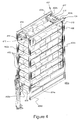
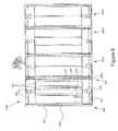
図4は、本発明の主題の一実施形態の斜視図である。図5は、本発明の主題の別の実施形態の斜視図である。図6は、図5の実施形態の上面図である。図7は、図5の実施形態の正面図である。図8は、図5の実施形態のさらなる斜視図である。参照および図示を容易にするために、図4〜8においては、車両の壁が省略されている。さらに、図5〜8が、複数のフレームおよび/またはベイ400a〜400dを有する実施形態を示し、図4が、ただ1つのベイ400aを有する実施形態を示すことに、注意すべきである。図4を参照すると、図1〜3に図示および/または上述した典型的な配送車両のいずれも、そのそれぞれのベイのうちの任意の1つまたは複数に、第1の矩形フレーム402および第2の矩形フレーム404を備えることができる。図4〜8を参照すると、これらの矩形フレーム402、404は、実質的に平行かつ互いに対面することができ、各々が2つの垂直部材402a、402b、404a、404bおよび2つの水平部材402c、402d、404c、404dを備えることができる。図5〜8のように、複数のベイ400a〜400dを有する実施形態においては、隣り合うベイが、矩形フレームを共有しても、しなくてもよい。典型的なベイは、所望の設計に応じて、標準型のベイ、絶縁式のベイ、または隔離式のベイであってよい。さらには、これらの矩形フレームを、他の矩形フレームに折り畳むことが可能であってよく、ならびに/あるいは他の矩形フレームと入れ子にできてもよいと考えられる。そのような実施形態においては、矩形フレームをトラック機構に可動に取り付けることができ、さらに後述されるように、一旦第1組のフレームまたはベイの製品が空になったならば、隣のベイまたはフレームを第1のフレームに畳み、隣のフレームの製品を送り出すことができる。
FIG. 4 is a perspective view of one embodiment of the present subject matter. FIG. 5 is a perspective view of another embodiment of the present inventive subject matter. 6 is a top view of the embodiment of FIG. FIG. 7 is a front view of the embodiment of FIG. FIG. 8 is a further perspective view of the embodiment of FIG. For ease of reference and illustration, the walls of the vehicle are omitted in FIGS. Furthermore, it should be noted that FIGS. 5-8 show an embodiment with multiple frames and / or
垂直部材402a、402b、404a、404bのいずれか、または各々に、直線ギア406が取り付けられてよい。直線ギア406は、それぞれの垂直部材の任意の部分または全長にわたって延びていてよい。2つの矩形フレーム402、404の内側に、保持構造410を収めることができる。好ましくは、両方の矩形フレーム402、404が保持構造410に係合し、保持構造410は、角において矩形フレーム402、404の垂直部材402a、402b、404a、404bの各々に隣接する水平フレーム412またはトレイを備えることができる。当然ながら、複数の水平フレーム412またはトレイが、本発明の主題の実施形態に含まれてよく、図4における8つのトレイの図示は、決して添付の特許請求の範囲の技術的範囲を限定するものではない。さらに、水平フレーム412のうちの任意の数の水平フレームを、いくつかの水平ビン(horizontal bin)413に仕切ることができる。例えば、一実施形態においては、水平フレーム412が、3つのビンを含むことができる。水平フレーム412のさらなる実施形態は、1つ、2つ、または4つ以上のビンを含むことができる。
A
保持構造410は、それぞれのシャフト416、417に係合する1つ以上のモータ414、415も備えることができる。モータ414、415を、一番上の水平フレーム412またはトレイに取り付けられたモータ保持アセンブリ440、441に着脱可能に取り付けることができる。典型的なモータは、電動モータ、油圧モータなどであってよいが、これらに限られるわけではない。シャフト416、417の各々の端部が、該当および/または隣接の垂直部材402a、402b、404a、404bの直線ギア406に回転可能に係合するギア419を受けることができる。シャフト416、417は、アセンブリ440、441の一部分の穿孔または穴を通って延びることができる。当然ながら、モータ、ギア、シャフトまたはリンク、ならびにモータ保持アセンブリの図示、構成、および空間的関係は、あくまでも例示にすぎず、添付の特許請求の範囲の技術的範囲を限定するものではない。複数の水平フレームまたはトレイ412を有する本発明の主題の実施形態においては、図4〜8のベイ400aに示されているように、1つ以上のモータ414、415の動作により、垂直運動の方向に応じて、隣接する水平フレーム412を残りの水平フレームに対して伸縮させることができる。例えば、複数の水平フレーム412を有する実施形態において、水平フレーム412の適切な伸縮を補助するために、各々のフレームに、先端部が球状またはストッパを有する案内ピンまたはロッド460を取り付けることができる。案内ピン460を、同じベイ400aに含まれる各々のフレーム412の穴464を通って延ばすことができる。このようにして、例えばモータ414、415が保持構造410の高さを増加させるように作動されるとき、一番上のフレームが上昇し、一番上のフレームの直下に位置する第2のフレームに取り付けられたロッド460の先端部のストッパと係合する。この第2のフレームがやはり上昇するとき、この第2のフレームが、最終的に、この第2のフレームの直下に位置する第3のフレームに取り付けられた別のロッド460の先端部462のストッパに係合し、以下同様である。同じことが、逆ではあるが、フレームを互いに畳む場合にも当てはまる。当然ながら、案内ピン460の長さを、最終的な高さまたは隣接するフレーム間の間隔を変更するために調節することができ、ピン460の先端部462のストッパまたは球のサイズを、所定のフレームだけの係合を保証し、あるいは該当のフレームの昇降を可能にするように変えることができる。
The retaining
さらに、2つの矩形フレーム402、404の内側に、1つ以上のベルト420を収めることができる。ベルト420を、2つの矩形フレーム402、404の下方の水平部材402d、404dの間に配置することができる。当然ながら、水平フレーム412におけるビン413の数に応じて、対応する数のベルト420が、それぞれのフレーム404、404の間に配置されると考えられる。例えば、図4が、3つのビン413を、該当の水平フレーム412および対応する数(各々のビンに1つずつ)のベルト420とともに示す。しかしながら、この例は、添付の特許請求の範囲の技術的範囲を限定するものではない。なぜならば、任意の数の該当の水平フレーム412およびそれらのそれぞれのビン413について、任意の数のベルトを利用できると考えられるからである。このようにして、モータ414、415の動作が、2つの矩形フレーム402、404からなる境界の内側での保持構造410の垂直移動をもたらすことができ、ベルト420の動作が、2つの矩形フレーム402、404からなる境界の内側での横移動または水平移動、したがってそれぞれの水平フレーム412またはビン413から個人への製品または貨物の移動をもたらすことができる。当然ながら、各々のベルト420の運動は、他のベルトの運動と無関係であってよく、そのような運動を、モータ、電気、油圧、または他の方法で達成することができる。モータ414、415の動作、したがって垂直移動は、自動化されても、手動であってもよいと考えられる。さらに、ベルト420の動作も、自動化されても、手動であってもよいと考えられる。例えば、下方の高さの製品が空になったときに、保持構造を(自動または手動で)畳んで、次の高さの製品を下方の高さにもたらすことができる。本発明の主題の実施形態を、上述の保持構造を利用するものとして説明したが、プーリ機構、チェーンまたはチェーン機構、油圧機構およびリフト、など、他の機械的なアセンブリも考えられるため、添付の特許請求の範囲は、上述の保持構造の利用に限られない。さらに、図4〜8のベイ400a〜400dへのアクセスは、側面からのアクセスと解釈することができるが、1つ以上のベイを有する実施形態が、貨物へのアクセスが後方からのアクセスに限られる車両に含まれる可能性があるため、添付の特許請求の範囲は、側面からのアクセスに限られない。当然ながら、ベイ400a〜400dへのアクセスは、巻き上げドアまたはスイングドアを介することができる。
Furthermore, one or
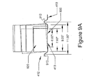
図9Aおよび9Bは、本発明の主題の実施形態による水平フレームの図である。図9Aおよび9Bを参照すると、典型的な水平フレーム412またはトレイは、水平フレーム412上に位置する貨物または製品920を保持するためのリッジ(ridge)または隆起部910を備えることができる。水平フレーム412が複数のビン413を備える本発明の主題の実施形態においては、隣接するビンの製品を互いに干渉することがないように保持するために、ビン413の間に分離用のリッジ912を設けることができる。下方のベルト420(不図示)に対応するために、水平フレーム412および個々のビン413は、ベルト420を水平フレーム412またはビン413に位置する製品920に接触させて、そのような製品920の横移動をもたらすことができる開口930を備えることができる。当然ながら、開口930の幅は、種々の寸法の製品(例えば、ケースなど)に対応するように調節可能であってよい。開口930の幅は、固定されていて調節不可能であってもよい。図10は、本発明の主題の実施形態が対応可能な製品920または貨物の典型的な寸法の斜視図である。図9A、9B、および10を参照すると、開口930の幅の調節を通じて、本発明の主題の実施形態が、幅広く様々な寸法を有する製品920または貨物を受け入れ、収容し、個人にもたらすことができることが明らかである。当然ながら、図9A、9B、および10に示した製品は、あくまでも例示にすぎず、添付の特許請求の範囲の技術的範囲を限定するものではない。例えば、下記の表6が、この業界において利用されるいくつかの飲料製品の一般的な寸法を示す。通常は、これらの製品は、5.5インチ〜約12.5インチの範囲の高さを有する。
(表6)
製品 1日当たり 1日当たり 1日当たり ケース幅 ケース
のケース のケース のケース (インチ)長さ
数 数 数 (インチ)
% 累積%
Lite 24pk can 574 8.5 8.5 10.8 16.1
Corona 12pk ln 2 245 3.6 12.1 11.0 16.0
Lite 6pk ln 4 231 3.4 15.5 10.5 15.5
High Life 24pk can 211 3.1 18.6 10.8 16.1
Steel reserve 24oz 175 2.6 21.2 9.0 12.0
can 12pk
Best lt. 24pk can 172 2.5 23.7 10.8 16.1
Lite 12pk ln2 166 2.4 26.2 10.5 15.5
High Life 12pk ln2 165 2.4 28.6 10.5 15.5
Lite 18pk can 162 2.4 31.0 7.9 15.6
Lite 20/12 lnnr 160 2.4 33.3 10.3 12.9
Lite Fridge 12pk can 138 2.0 35.4 10.8 16.1
Best Ice 24pk can 125 1.9 37.2 10.8 16.1
Red Bull Energy Drink 123 1.8 39.1 9.0 13.0
Corona 6pk ln/4 122 1.8 40.9 11.0 16.0
High Life 40 oz nr 12 106 1.6 42.4 11.8 15.4
Best Ice 12pk can 2 96 1.4 43.8 7.9 10.5
Icehouse 24oz can/12 88 1.3 45.1 9.0 12.0
Best 24pk cans 85 1.3 46.4 10.8 16.1
Icehouse 12pk ln 2 74 1.1 48.7 10.5 15.5
Icehouse 22oz nr 15 73 1.1 49.8 9.0 15.0
Best lt. 12pk can 2 70 1.0 50.8 7.9 10.5
Icehouse 18/12 lnnr 69 1.0 51.8 7.8 15.0
High Life Fridge pack
(2/12) 67 1.0 52.8 10.8 16.1
Canada Dry Ginger Ale
8/2L 66 1.0 53.8 10.0 19.0
High Life 6pk ln 4 65 1.0 54.7 10.5 15.5
Icehouse 6pk ln 63 0.9 55.7 10.5 15.5
9A and 9B are illustrations of horizontal frames according to embodiments of the present inventive subject matter. With reference to FIGS. 9A and 9B, a typical
(Table 6)
Product Per day Per day Per day Case width Case
Case Case Case Case (inch) Length
Number Number Number (inch)
% Accumulation%
Lite 24pk can 574 8.5 8.5 10.8 16.1
Corona 12pk ln 2 245 3.6 12.1 11.0 16.0
Lite 6pk ln 4 231 3.4 15.5 10.5 15.5
High Life 24pk can 211 3.1 18.6 10.8 16.1
Steel reserve 24oz 175 2.6 21.2 9.0 12.0
can 12pk
Best lt. 24pk can 172 2.5 23.7 10.8 16.1
Lite 12pk ln2 166 2.4 26.2 10.5 15.5
High Life 12pk ln2 165 2.4 28.6 10.5 15.5
Lite 18pk can 162 2.4 31.0 7.9 15.6
Lite Fridge 12pk can 138 2.0 35.4 10.8 16.1
Best Ice 24pk can 125 1.9 37.2 10.8 16.1
Red Bull Energy Drink 123 1.8 39.1 9.0 13.0
Corona 6pk ln / 4 122 1.8 40.9 11.0 16.0
Best Ice 12pk can 2 96 1.4 43.8 7.9 10.5
Icehouse 24oz can / 12 88 1.3 45.1 9.0 12.0
Best 24pk cans 85 1.3 46.4 10.8 16.1
Icehouse 12pk ln 2 74 1.1 48.7 10.5 15.5
Icehouse 22oz nr 15 73 1.1 49.8 9.0 15.0
Best lt. 12pk can 2 70 1.0 50.8 7.9 10.5
Icehouse 18/12 lnnr 69 1.0 51.8 7.8 15.0
High Life Fridge pack
(2/12) 67 1.0 52.8 10.8 16.1
Canada Dry Ginger Ale
8 / 2L 66 1.0 53.8 10.0 19.0
High Life 6pk ln 4 65 1.0 54.7 10.5 15.5
Icehouse 6pk ln 63 0.9 55.7 10.5 15.5
当然ながら、本発明の主題の実施形態は、様々な寸法を有する様々な産業(乳業、自動販売機産業、製パン業、スナック食品産業、など)からの貨物および製品に対応することができるため、表6の上記のデータはあくまでも例示にすぎず、添付の特許請求の範囲の技術的範囲を限定するものではない。 Of course, embodiments of the present inventive subject matter can accommodate cargo and products from different industries (dairy, vending machine industry, bakery industry, snack food industry, etc.) having different dimensions. The above data in Table 6 is merely an example, and does not limit the technical scope of the appended claims.
図11は、本発明の主題の一実施形態のブロック図である。図11を参照すると、車両に製品を積み込み、ならびに/あるいは製品を個人または顧客に届ける方法1100が、ステップ1110において、1つ以上の機構を動作させることを含むことができ、ステップ1120において、前記1つ以上の機構を使用して車両のベイ内で製品を垂直方向および横方向に移動させることを含むことができる。典型的な車両は、既に言及および説明した配送車両のいずれかを含むことができ、上述の通りの2つの典型的な矩形フレームを有し、各々のフレームが2つの水平部材および2つの垂直部材を有し、各々のフレームが互いに向かい合っている少なくとも1つのベイを備えることができる。さらにベイは、上述のように、製品を載せる1つ以上の水平トレイを備える典型的な保持構造を両方の矩形フレームに係合させて備えることができる。一実施形態においては、前記機構のうちの1つがモータであってよく、モータの動作が、1つ以上の水平トレイを垂直移動にて伸縮させると考えられる。別の実施形態においては、前記機構のうちの1つがベルトであってよく、ベルトの動作が、1つ以上の水平トレイから製品を横方向に移動させると考えられる。当然ながら、この横方向および/または垂直方向の移動は、自動または手動であってよい。
FIG. 11 is a block diagram of one embodiment of the present subject matter. Referring to FIG. 11, a
図12は、本発明の主題の別の実施形態のブロック図である。図12を参照すると、顧客への製品の配送を追跡する方法1200が、ステップ1210において、製品を特定するための符号を割り当てることを含むことができ、ステップ1220において、製品を配送車両に積み込むことを含むことができる。車両は、上述のように、保持構造を支える垂直フレームとベルトアセンブリとを有する1つ以上の配送ベイを備えることができる。典型的な符号は、これらに限られるわけではないが、最小在庫管理単位(Stock−Keeping Unit:SKU)、統一商品コード(Universal Product Code:UPC)、欧州物品番号(European Article Number:EAN)、国際取引品番号(Global Trade Item Number:GTIN)、価格参照(Price look−up:PLU)コード、およびオーストラリア製品番号(Australian Product Number:APN)であってよい。さらに、方法1200は、ステップ1230において、品物を配送車両から下ろすことを含むことができ、ステップ1240において、前記符号を使用して製品の配送を追跡することを含むことができる。当然ながら、ステップ1220または1230の一方または両方は、車両の1つ以上の配送ベイにおいて製品について保持構造を使用して垂直移動をもたらし、ベルトアセンブリを使用して横方向の移動をもたらすことを含むことができる。一実施形態においては、垂直または水平移動のいずれかまたは両方が、自動または手動であってよい。さらなる実施形態においては、そのような自動化された移動または自動的な移動が、割り当てられた符号の関数であってよい。例えば、個人または作業者が、車両のベイにおける荷下ろし(または、積み込み)の際に、特定のSKUまたは一連のSKUを携帯デバイスまたは車両に取り付けられたデバイスに入力することができると考えられる。デバイスが無線または有線接続を介してデータベースまたはメモリユニットと通信し、SKUまたは一連のSKUに対応する製品の位置が発見される。次いで、そのような位置に応じて、製品が、先の段落において説明した垂直方向および横方向の移動によって、個人または作業者に(あるいは、個人または作業者から)自動または手動でもたらされる。
FIG. 12 is a block diagram of another embodiment of the present inventive subject matter. Referring to FIG. 12, a
このように、本発明の主題の実施形態を利用することで、製品が個人に提示されるがゆえに、配送におけるドアの開放および/または製品の捜索に費やされる時間がわずかまたは皆無であり、したがって配送に必要なケースにたどり着くためにケースを取り扱う無駄時間がなくなる。さらに、現在の地理的領域における配送数の増加および/または1台の配送車両が担当する地理的領域の拡大を通じ、流通プロセスの効率の向上を見て取ることができる。加えて、製品が腰または地面の高さにおいて作業者に提示されるため、人間工学に関連した負傷のコストなど、人間工学に関連した問題がなくなる。さらに、本発明の主題の実施形態を利用する各々の配送車両の設計において最大積載量を増やすことができる。また、典型的な実施形態は、新たな梱包に関係したケースのサイズの急増に対応することもでき、したがって全体としての車両の容量に不利益をもたらすことなく大小の注文量に車両の設計を対応させることができる。 Thus, by utilizing embodiments of the present subject matter, little or no time is spent opening doors and / or searching for products in the delivery because the product is presented to an individual. There is no wasted time handling the case to reach the case required for delivery. In addition, an increase in the efficiency of the distribution process can be seen through an increase in the number of deliveries in the current geographical area and / or an expansion of the geographical area served by a single delivery vehicle. In addition, because the product is presented to the operator at the waist or ground level, ergonomic issues such as ergonomic injury costs are eliminated. Further, the maximum loading can be increased in each delivery vehicle design utilizing embodiments of the present subject matter. The exemplary embodiment can also accommodate the sudden increase in case size associated with new packaging, thus reducing vehicle design to large and small order quantities without penalizing overall vehicle capacity. Can be matched.
したがって、本発明の主題の実施形態の態様は、現在の配送業界(例えば、飲料、乳製品、自動販売機、製パン、スナック食品、などの産業における製品の配送)における限界を克服し、成長する製品の品揃えおよび/または梱包の寸法ならびに増大する顧客の要求に追従および対応するダイナミックな技術的解決策を提供する。本発明の主題の実施形態の他の態様は、配送車両の設計に重要な変化をもたらすことによる性能の改善、配送車両の容量の増加、配送車両において利用できる三次元空間の最大化、および製品の配送コストの削減である。したがって、本発明の主題の実施形態は、最も前方の位置において地面または腰の高さで配送運転手に製品を提示することができ、したがってドアの開閉の回数を最小化することができ、配送運転手の過度の緊張およびストレスを取り除くことができる。 Accordingly, aspects of embodiments of the present subject matter overcome and grow the limitations in the current delivery industry (eg, delivery of products in the beverage, dairy, vending machine, bread making, snack food, etc. industries). Providing a dynamic technical solution that follows and responds to the assortment and / or packaging dimensions of the products to be fulfilled and the increasing customer demands. Other aspects of embodiments of the present subject matter include improved performance by bringing significant changes to delivery vehicle design, increased delivery vehicle capacity, maximization of the three-dimensional space available in the delivery vehicle, and product It is a reduction of the delivery cost. Thus, embodiments of the present subject matter can present products to the delivery driver at the level of the ground or waist in the foremost position, thus minimizing the number of door opening and closing times, The driver's excessive tension and stress can be relieved.
上記の説明は、典型的なトラックまたは横ベイ型の配送車両に言及でき、あるいは典型的なトラックまたは横ベイ型の配送車両を提供できるが、これを添付の特許請求の範囲の技術的範囲を限定するものとして解釈してはならない。当業者にとって公知である通り、他の典型的な配送車両として、後ろ積みもしくは横ベイならびに/あるいは後ろベイまたは後ろ積みの組み合わせの車両(例えば、ハイブリッド)、トラック、バン、および他のそのような車輪付きの車両を挙げることができる。さらに、以下の説明においては、飲料の容器およびケースなどに言及する場合があるが、これも、添付の特許請求の範囲の技術的範囲を限定するものではない。なぜならば、本発明の主題の実施形態は、乳業、自動販売機産業、製パン業、スナック食品産業、ならびに消耗品であっても、消耗品でなくても、横ベイおよび/または後ろ積みの配送車両を利用することができる任意の産業において、配送車両のための容器、ケース、製品、および/または貨物に等しく適用可能であるからである。 The above description can refer to a typical truck or side bay delivery vehicle, or can provide a typical truck or side bay delivery vehicle, which is within the scope of the appended claims. It should not be construed as limiting. As is known to those skilled in the art, other typical delivery vehicles include back-loaded or side bays and / or rear bay or back-loaded combinations of vehicles (eg, hybrids), trucks, vans, and other such Mention may be made of vehicles with wheels. Furthermore, in the following description, a beverage container and a case may be referred to, but this also does not limit the technical scope of the appended claims. Because embodiments of the present inventive subject matter can be found in the dairy industry, vending machine industry, bakery industry, snack food industry, and horizontal bays and / or backpacks, whether consumable or non-consumable. This is because in any industry where delivery vehicles can be utilized, it is equally applicable to containers, cases, products, and / or cargo for delivery vehicles.
図1〜12に示した種々の構成および実施形態によって示される通り、人間工学的に改良された配送車両および方法を説明した。 An ergonomically improved delivery vehicle and method has been described, as illustrated by the various configurations and embodiments shown in FIGS.
本発明の主題の好ましい実施形態を説明したが、説明された実施形態があくまでも例示にすぎず、本発明の技術的範囲が、添付の特許請求の範囲によってのみ、均等物の全範囲ならびに添付の特許請求の範囲を精読することによって当業者が自然に思い到る多数の変種および変形を含んで定められることを、理解すべきであろう。 Although preferred embodiments of the subject matter of the present invention have been described, the described embodiments are merely illustrative, and the technical scope of the present invention is limited only by the appended claims, as well as the full scope of equivalents, It should be understood that numerous variations and modifications will occur to those skilled in the art upon a thorough reading of the claims.
100 配送車両
102 前車軸
104 後車軸
110 ベイ
111 ベイ
112 ベイ
200 配送車両
202 前車軸
203 駆動軸
204 後車軸
210 ベイ
211 ベイ
212 ベイ
300 配送車両
302 前車軸
303 駆動軸
304 後車軸
310 ベイ
312 ベイ
314 ベイ
400a、400b、400c、400d ベイ
402 矩形フレーム
402a、402b 垂直部材
402c、402d 水平部材
404 矩形フレーム
404a、404b 垂直部材
404c、404d 水平部材
406 直線ギア
410 保持構造
412 水平フレーム(トレイ)
413 水平ビン
414 モータ
415 モータ
416 シャフト
417 シャフト
419 ギア
420 ベルト
440 モータ保持アセンブリ
441 モータ保持アセンブリ
460 案内ピン(ロッド)
462 ロッド460の先端部
464 フレーム412の穴
910 リッジ(隆起部)
912 リッジ
920 製品
930 開口
DESCRIPTION OF
413
462 Tip of
912
Claims (9)
対面した前記矩形フレームに係合した保持構造であって、
角において前記対面した矩形フレームの各々の前記垂直部材の各々に隣接し、かつ、複数の水平ビンに仕切られる第1の水平フレームおよび第2の水平フレームと、
一のシャフトに係合するように構成された第1のモータと、もう一つのシャフトに係合するように構成された第2のモータとを備え、
前記一のシャフトともう一つのシャフトが各々の前記シャフトの両端にギアを有し、各々のシャフトのギアがそれぞれの垂直部材の前記直線ギアに回転可能に係合し、前記第2のモータが係合する前記直線ギアは、前記第1のモータの係合する前記直線ギアの反対側にある保持構造と、
前記2つの矩形フレームの前記下方の水平部材の間に並んで配置された第1のベルトおよび第2のベルトを備え、
前記第1のベルトと第2のベルトの各々が、別々の水平ビンからの横移動をもたらすように配置され、
前記第1のモータと第2のモータの動作が、前記対面した矩形フレームからなる境界の内側での前記保持構造の垂直移動をもたらし、
前記第1のベルトと第2のベルトの各々の動作が、もう一つのモータによって前記2つの矩形フレームからなる境界の内側での横移動をもたらし、
前記第1のモータと第2のモータの動作により、前記第2の水平フレームが前記第1の水平フレームに畳まれる配送車両。 Have two or more parallel rectangular frames, each frame has two horizontal members and two vertical members, each frame face each other, the vertical member of each frame, the respective A plurality of horizontally stacked bays with linear gears attached to a portion of the total length of the vertical member;
A holding structure engaged with the rectangular frame facing each other ,
Adjacent each of said vertical members of each of the rectangular frame the face at the corner, and a first horizontal frame and a second horizontal frame Ru partitioned into a plurality of horizontal bins,
A first motor configured to engage one shaft and a second motor configured to engage another shaft ;
Has a gear on both ends of the shaft of the other shaft with the one shaft each, each of the shafts of the gears rotatably engage the linear gear of each vertical member, said second motor It said linear gear engaged is the opposite side near Ru holding structure of the linear gear to engagement of the first motor,
A first belt and a second belt arranged side by side between the lower horizontal members of the two rectangular frames;
Each of the first belt and the second belt is arranged to provide lateral movement from a separate horizontal bin;
The movement of the first motor and the second motor results in a vertical movement of the holding structure inside the boundary of the facing rectangular frames;
The operation of each of the first belt and second belt, and cod also lateral movement of the inside of the border consisting of the two rectangular frames by another motor,
A delivery vehicle in which the second horizontal frame is folded onto the first horizontal frame by the operations of the first motor and the second motor .
1つ以上の機構を動作させるステップと、
前記1つ以上の機構を使用して前記車両のベイにおいて製品に垂直および横移動を付与するステップとを含み、
前記車両が、
2つ以上の平行な矩形フレームを有し、各々のフレームが2つの水平部材および2つの垂直部材を有し、各々のフレームが互いに対面し、各々のフレームの前記垂直部材が、前記それぞれの垂直部材の全長のうちの一部分に取り付けられた直線ギアを備える横積み型の複数のベイと、
対面した前記矩形フレームに係合した保持構造であって、
角において前記2つの矩形フレームの各々の前記垂直部材の各々に隣接し、かつ、複数の水平ビンに仕切られる第1の水平フレームおよび第2の水平フレームと、
一のシャフトに係合するように構成された第1のモータと、もう一つのシャフトに係合するように構成された第2のモータを備え、
前記一のシャフトともう一つのシャフトが各々の前記シャフトの両端にギアを有し、各々のシャフトのギアがそれぞれの垂直部材の前記直線ギアに回転可能に係合し、前記第2のモータが係合する前記直線ギアは、前記第1のモータの係合する前記直線ギアの反対側にある保持構造と、
前記2つの矩形フレームの前記下方の水平部材の間に並んで配置された第1のベルトおよび第2のベルトを備え、前記第1のベルトと第2のベルトの各々が、別々の水平ビンからの横移動をもたらすように配置され、
前記第1のモータと第2のモータの動作が、前記対面した矩形フレームからなる境界の内側での前記保持構造の垂直移動をもたらし、
前記第1のベルトと第2のベルトの各々の動作が、もう一つのモータによって前記2つの矩形フレームからなる境界の内側での横移動をもたらし、
前記第1のモータと第2のモータの動作により、前記第2の水平フレームが前記第1の水平フレームに畳まれる構造
を備える方法。 A method of loading a product into a vehicle or delivering a product from a vehicle to an individual,
Operating one or more mechanisms;
Using the one or more mechanisms to impart vertical and lateral movement to a product in the bay of the vehicle,
The vehicle
Have two or more parallel rectangular frames, each frame has two horizontal members and two vertical members, each frame face each other, the vertical member of each frame, the respective A plurality of horizontally stacked bays with linear gears attached to a portion of the total length of the vertical member;
A holding structure engaged with the rectangular frame facing each other ,
Adjacent each of said vertical members of each of the two rectangular frames at the corners, and a first horizontal frame and a second horizontal frame Ru partitioned into a plurality of horizontal bins,
A first motor configured to engage one shaft and a second motor configured to engage another shaft ;
Has a gear on both ends of the shaft of the other shaft with the one shaft each, each of the shafts of the gears rotatably engage the linear gear of each vertical member, said second motor It said linear gear engaged is the opposite side near Ru holding structure of the linear gear to engagement of the first motor,
A first belt and a second belt arranged side by side between the lower horizontal members of the two rectangular frames, each of the first belt and the second belt from a separate horizontal bin; Arranged to bring about lateral movement of
The movement of the first motor and the second motor results in a vertical movement of the holding structure inside the boundary of the facing rectangular frames;
The operation of each of the first belt and second belt, and cod also lateral movement of the inside of the border consisting of the two rectangular frames by another motor,
A method comprising a structure in which the second horizontal frame is folded into the first horizontal frame by the operation of the first motor and the second motor .
製品を特定するための符号を、最小在庫管理単位(SKU)、統一商品コード(UPC)、欧州物品番号(EAN)、国際取引品番号(GTIN)、価格参照(PLU)コード、およびオーストラリア製品番号(APN)で構成される群から選択し、選択した前記符号を製品に割り当てるステップと、
2つ以上の平行な矩形フレームを有し、各々のフレームが2つの水平部材および2つの垂直部材を有し、各々のフレームが互いに対面し、各々のフレームの前記垂直部材が、前記それぞれの垂直部材の全長のうちの一部分に取り付けられた直線ギアを備える横積み型の複数のベイと、
対面した前記矩形フレームに係合した保持構造であって、
角において前記対面した矩形フレームの各々の前記垂直部材の各々に隣接し、かつ、複数の水平ビンに仕切られる第1の水平フレームおよび第2の水平フレームと、一のシャフトに係合するように構成された第1のモータともう一つのシャフトに係合するように構成された第2のモータとを備え、
前記一のシャフトともう一つのシャフトが各々の前記シャフトの両端にギアを有し、各々のシャフトのギアがそれぞれの垂直部材の前記直線ギアに回転可能に係合し、前記第2のモータが係合する前記直線ギアは、前記第1のモータの係合する前記直線ギアの反対側にある保持構造と、
前記対面した矩形フレームの前記下方の水平部材の間に並んで配置された第1のベルトと第2のベルトとを備え、前記第1のベルトと第2のベルトの各々が、別々の水平ビンからの横移動をもたらすように配置され、
前記第1のモータと第2のモータの動作が、前記対面した矩形フレームからなる境界の内側での前記保持構造の垂直移動をもたらし、
前記第1のベルトと第2のベルトの各々の動作が、もう一つのモータによって前記2つの矩形フレームからなる境界の内側での横移動をもたらし、
前記第1のモータと第2のモータの動作により、前記第2の水平フレームが前記第1の水平フレームに畳まれる配送車両に、前記符号が割り当てられた製品を積み込むステップと、
前記配送車両から前記符号が割り当てられた製品を下ろすステップと、
割り当てられた前記符号を使用してその符号が割り当てられた製品の配送を追跡するステップとを含み、
前記積み込むステップまたは下ろすステップの少なくとも一方が、前記車両のベイにおいて、前記保持構造を使用して製品の垂直移動をもたらし、前記ベルトを使用して製品の横移動をもたらすことをさらに含み、
前記垂直移動または横移動の少なくとも一方が自動的であるとき、前記移動が、前記割り当てられた符号の関数でなされることを含む方法。 A method of tracking the delivery of a product to a customer,
The codes used to identify products are: Minimum Inventory Control Unit (SKU), Unified Product Code (UPC), European Article Number (EAN), International Trade Item Number (GTIN), Price Reference (PLU) Code, and Australian Product Number Selecting from the group consisting of (APN) and assigning the selected code to a product ;
Have two or more parallel rectangular frames, each frame has two horizontal members and two vertical members, each frame face each other, the vertical member of each frame, the respective A plurality of horizontally stacked bays with linear gears attached to a portion of the total length of the vertical member;
A holding structure engaged with the rectangular frame facing each other ,
Adjacent each of said vertical members of each of the rectangular frame the face at the corner, and a first horizontal frame and a second horizontal frame Ru partitioned into a plurality of horizontal bins, to engage one of the shaft A first motor configured to and a second motor configured to engage another shaft ;
Has a gear on both ends of the shaft of the other shaft with the one shaft each, each of the shafts of the gears rotatably engage the linear gear of each vertical member, said second motor It said linear gear engaged is the opposite side near Ru holding structure of the linear gear to engagement of the first motor,
A first belt and a second belt arranged side by side between the lower horizontal members of the facing rectangular frame, wherein each of the first belt and the second belt is a separate horizontal bin; Arranged to bring lateral movement from
The movement of the first motor and the second motor results in a vertical movement of the holding structure inside the boundary of the facing rectangular frames;
The operation of each of the first belt and second belt, and cod also lateral movement of the inside of the border consisting of the two rectangular frames by another motor,
Loading the product assigned the code into a delivery vehicle in which the second horizontal frame is folded into the first horizontal frame by the operation of the first motor and the second motor ;
Dropping the product assigned the code from the delivery vehicle;
Using the assigned code to track the delivery of the product to which the code is assigned ,
At least one of said loading steps or down steps in the bay of the vehicle, results in a vertical movement of the products using the retention structure further seen including that resulting lateral movement of the product using the belt,
The method comprising: when at least one of the vertical movement or the horizontal movement is automatic, the movement is made as a function of the assigned sign .
Applications Claiming Priority (3)
| Application Number | Priority Date | Filing Date | Title |
|---|---|---|---|
| US13/187,871 US9073470B2 (en) | 2011-07-21 | 2011-07-21 | Ergonomically improved delivery vehicle and method |
| US13/187,871 | 2011-07-21 | ||
| PCT/US2012/047316 WO2013013000A2 (en) | 2011-07-21 | 2012-07-19 | Ergonomically improved delivery vehicle and method |
Publications (2)
| Publication Number | Publication Date |
|---|---|
| JP2014524869A JP2014524869A (en) | 2014-09-25 |
| JP6030129B2 true JP6030129B2 (en) | 2016-11-24 |
Family
ID=47556502
Family Applications (1)
| Application Number | Title | Priority Date | Filing Date |
|---|---|---|---|
| JP2014521756A Active JP6030129B2 (en) | 2011-07-21 | 2012-07-19 | Ergonomically improved delivery vehicle and method |
Country Status (5)
| Country | Link |
|---|---|
| US (2) | US9073470B2 (en) |
| EP (2) | EP3552876B1 (en) |
| JP (1) | JP6030129B2 (en) |
| CA (1) | CA2842428C (en) |
| WO (1) | WO2013013000A2 (en) |
Families Citing this family (18)
| Publication number | Priority date | Publication date | Assignee | Title |
|---|---|---|---|---|
| DE102015111033A1 (en) * | 2015-07-08 | 2017-01-12 | Deutsche Post Ag | Device and method for flexible collection and / or delivery of a shipment |
| CN105083092B (en) * | 2015-07-10 | 2017-04-19 | 芜湖市海洋物流有限公司 | Automated transportation loading and unloading car for logistics |
| CN105059403A (en) * | 2015-07-31 | 2015-11-18 | 谢子聪 | Carriage body system of mobile charging vehicle used for replacing power battery of electric passenger vehicle |
| CN105236162B (en) * | 2015-09-06 | 2017-11-24 | 巨石集团有限公司 | A kind of pallet discharge apparatus |
| WO2017120090A1 (en) * | 2016-01-06 | 2017-07-13 | Russell David Wayne | System and method for autonomous shelving units |
| CN106570667B (en) * | 2016-10-25 | 2020-08-21 | 北京印刷学院 | Express delivery distribution method based on vehicle-express cabinet-unmanned aerial vehicle |
| CN106570666B (en) * | 2016-10-25 | 2020-08-21 | 北京印刷学院 | Intelligent control system applied to express delivery conveying device |
| CN106541880B (en) * | 2016-10-25 | 2019-04-12 | 北京印刷学院 | A kind of Intelligent transportation device |
| CN106429162A (en) * | 2016-12-08 | 2017-02-22 | 成都天航智虹企业管理咨询有限公司 | Distribution box |
| CN106671853A (en) * | 2016-12-30 | 2017-05-17 | 重庆大学 | Express carrying device |
| WO2018231756A1 (en) * | 2017-06-16 | 2018-12-20 | Walmart Apollo, Llc | Systems and methods for loading totes using hydraulic lifts |
| NO20180031A1 (en) * | 2018-01-09 | 2019-07-10 | Autostore Tech As | Automated storage and retrieval system, a container handling vehicle which can operate on an automated storage and retrieval system and a method of operating an automated storage and retrieval system |
| CN107972552A (en) * | 2018-01-15 | 2018-05-01 | 钦州学院 | A kind of mobile bee-keeper of quick despatch beehive |
| CN108791925A (en) * | 2018-06-15 | 2018-11-13 | 南通嗨森无人机科技有限公司 | A kind of civilian express delivery load-carrying unmanned plane |
| WO2020102900A1 (en) * | 2018-11-20 | 2020-05-28 | Advanced Intelligent Systems Inc. | Systems, methods, and storage units for article transport and storage |
| CO2019010919A1 (en) * | 2019-10-01 | 2021-04-08 | Pontificia Univ Javeriana | Material loading and unloading mechanism for a container |
| EP3974251B1 (en) * | 2020-09-25 | 2023-11-29 | Jungheinrich Aktiengesellschaft | Delivery vehicle |
| KR20220045637A (en) * | 2020-10-06 | 2022-04-13 | 현대자동차주식회사 | Stack the Parcel to the Cargo and the Method thereof |
Family Cites Families (24)
| Publication number | Priority date | Publication date | Assignee | Title |
|---|---|---|---|---|
| US2779487A (en) | 1955-01-14 | 1957-01-29 | Francis D Harris | Vehicle mounted handling device for pallet stacks |
| US2832636A (en) | 1956-02-06 | 1958-04-29 | Trailmoblie Inc | Elevating system for trailer center deck |
| DE2340692C3 (en) | 1973-08-10 | 1982-11-04 | Maschinenfabrik Fahr Ag Gottmadingen, 7702 Gottmadingen | Mobile device for automatically picking up, storing and delivering piece goods, in particular bales of hay or straw |
| US3929371A (en) | 1974-07-01 | 1975-12-30 | Louis J Gibson | Support means for stacks of articles |
| US4033620A (en) * | 1975-09-04 | 1977-07-05 | Blake Robert L | Bee hive carrier and transport means |
| US4139109A (en) | 1977-07-29 | 1979-02-13 | Murphy Robert P | Load lift assembly for trucks |
| US4294332A (en) * | 1979-04-13 | 1981-10-13 | Ready Delbert L | Scaffold with gear drive |
| CA1234373A (en) | 1986-02-10 | 1988-03-22 | Atlantis Projects Inc. | Transportation van having load elevating platform located therein |
| GB8617088D0 (en) | 1986-07-14 | 1986-08-20 | Hydraroll Ltd | Load handling system |
| US5092721A (en) | 1988-11-28 | 1992-03-03 | Coterie, Ltd. | Double drop trailer with two lifts |
| DE8907876U1 (en) * | 1989-06-28 | 1989-08-31 | Karosseriebau Heinrichs Gmbh, 4720 Beckum, De | |
| US5054295A (en) * | 1990-08-21 | 1991-10-08 | Goulooze Gene D | Transport with variable volume, independently cooled compartments |
| JPH04110243A (en) * | 1990-08-30 | 1992-04-10 | Anritsu Corp | Load carrying platform for loading vehicle |
| JP2961294B2 (en) * | 1994-06-30 | 1999-10-12 | 良三 太田 | Elevator |
| JPH0812092A (en) * | 1994-07-04 | 1996-01-16 | Kouritsu Gijutsu Kenkyusho:Kk | Vehicle loaded article accommodating device and method for accommodating and discharging article |
| US5931262A (en) | 1995-06-07 | 1999-08-03 | Greenlaw; Robert J. | Delivery vehicle with multi-tier storage of cargo |
| US6033002A (en) * | 1995-07-26 | 2000-03-07 | Clare; Scott | Collapsible material carrier and hidden storage system for vehicle beds |
| DE19809291A1 (en) * | 1998-03-05 | 1999-09-09 | Unterberg | Vehicle, and especially transport vehicle for holding objects |
| JP2000296995A (en) * | 1999-04-08 | 2000-10-24 | Toho Kenzai:Kk | Vertically moving loading unloading device |
| ITBO20020728A1 (en) * | 2002-11-19 | 2004-05-20 | Resta Srl | TEMPORARY STORAGE EQUIPMENT DEVICE, |
| US7036861B2 (en) * | 2003-02-10 | 2006-05-02 | Steffens Enterprises, Inc. | Cargo compartment organizer |
| EP1741594B2 (en) | 2005-07-07 | 2014-11-26 | Omar-S.R.L. | Apparatus and method for moving pallets |
| JP3133872U (en) * | 2007-05-15 | 2007-07-26 | 住友金属物流株式会社 | Holding equipment for the transportation of long-sized products |
| TWI615337B (en) * | 2009-04-10 | 2018-02-21 | 辛波提克有限責任公司 | Automated case unit storage system and method for handling case units that are configured for being arrayed into a palletized load of case units for shipping to or from a storage facility |
-
2011
- 2011-07-21 US US13/187,871 patent/US9073470B2/en active Active
-
2012
- 2012-07-19 EP EP19178113.7A patent/EP3552876B1/en active Active
- 2012-07-19 EP EP12814322.9A patent/EP2734412B1/en active Active
- 2012-07-19 WO PCT/US2012/047316 patent/WO2013013000A2/en active Application Filing
- 2012-07-19 CA CA2842428A patent/CA2842428C/en active Active
- 2012-07-19 JP JP2014521756A patent/JP6030129B2/en active Active
-
2015
- 2015-06-01 US US14/727,387 patent/US10507754B2/en active Active
Also Published As
| Publication number | Publication date |
|---|---|
| US10507754B2 (en) | 2019-12-17 |
| EP3552876A1 (en) | 2019-10-16 |
| WO2013013000A3 (en) | 2013-04-18 |
| EP2734412B1 (en) | 2019-06-05 |
| WO2013013000A2 (en) | 2013-01-24 |
| EP3552876B1 (en) | 2020-12-02 |
| US20150336497A1 (en) | 2015-11-26 |
| US9073470B2 (en) | 2015-07-07 |
| CA2842428C (en) | 2022-01-04 |
| JP2014524869A (en) | 2014-09-25 |
| CA2842428A1 (en) | 2013-01-24 |
| EP2734412A4 (en) | 2015-11-18 |
| EP2734412A2 (en) | 2014-05-28 |
| US20130024392A1 (en) | 2013-01-24 |
Similar Documents
| Publication | Publication Date | Title |
|---|---|---|
| JP6030129B2 (en) | Ergonomically improved delivery vehicle and method | |
| US9580097B2 (en) | Apparatus and method for efficiently transporting various articles | |
| US10661696B2 (en) | Vehicle insert and method of vehicle loading and unloading | |
| US6325586B1 (en) | Automated storage and retrieval system | |
| US3879053A (en) | Mobile display cart | |
| JP5848268B2 (en) | Warehouse system | |
| EP1931552B1 (en) | Apparatus for transporting products in crates or containers | |
| JPH11113643A (en) | Merchandise display method and merchandise display carriage in supermarket | |
| US20200138207A1 (en) | A system for efficiently supplying, transporting and dispensing consumable merchandise and novel racks therefor | |
| US9327952B1 (en) | Cart for moving items | |
| KR20210157420A (en) | Object handling system and method | |
| KR20230017320A (en) | Multifunctional Inventory Handling Station Assembly | |
| US20210323769A1 (en) | Transport rack cartridge (trc) | |
| JP3985971B1 (en) | Commodity bag transfer device | |
| CN214166199U (en) | Automatic goods picking warehouse | |
| US7588404B2 (en) | Container handling apparatus and container | |
| CN220096398U (en) | Logistics trolley with layered structure | |
| CN212861534U (en) | Carrying trolley for logistics transportation | |
| CN216334448U (en) | Double-deep cross beam type goods shelf for storage of pallet goods | |
| JP6707753B2 (en) | Delivery method in small-lot delivery system | |
| Shaffer et al. | Unloading and receiving produce in retail food stores | |
| JP2015024869A (en) | Conveyance system for picking commodity | |
| JP2023049061A (en) | Cargo loading device onto car truck | |
| US20060213150A1 (en) | Method for product handling using a configurable display container | |
| NO347132B1 (en) | An assembly comprising a storage cell and a goods holder, a module comprising a plurality of the assemblies and a storage and retrieval system comprising the module |
Legal Events
| Date | Code | Title | Description |
|---|---|---|---|
| A621 | Written request for application examination |
Free format text: JAPANESE INTERMEDIATE CODE: A621 Effective date: 20150721 |
|
| A977 | Report on retrieval |
Free format text: JAPANESE INTERMEDIATE CODE: A971007 Effective date: 20160421 |
|
| A131 | Notification of reasons for refusal |
Free format text: JAPANESE INTERMEDIATE CODE: A131 Effective date: 20160517 |
|
| A601 | Written request for extension of time |
Free format text: JAPANESE INTERMEDIATE CODE: A601 Effective date: 20160817 |
|
| A601 | Written request for extension of time |
Free format text: JAPANESE INTERMEDIATE CODE: A601 Effective date: 20160817 |
|
| A521 | Request for written amendment filed |
Free format text: JAPANESE INTERMEDIATE CODE: A523 Effective date: 20160908 |
|
| TRDD | Decision of grant or rejection written | ||
| A01 | Written decision to grant a patent or to grant a registration (utility model) |
Free format text: JAPANESE INTERMEDIATE CODE: A01 Effective date: 20161004 |
|
| A61 | First payment of annual fees (during grant procedure) |
Free format text: JAPANESE INTERMEDIATE CODE: A61 Effective date: 20161019 |
|
| R150 | Certificate of patent or registration of utility model |
Ref document number: 6030129 Country of ref document: JP Free format text: JAPANESE INTERMEDIATE CODE: R150 |
|
| S111 | Request for change of ownership or part of ownership |
Free format text: JAPANESE INTERMEDIATE CODE: R313113 |
|
| R350 | Written notification of registration of transfer |
Free format text: JAPANESE INTERMEDIATE CODE: R350 |
|
| R250 | Receipt of annual fees |
Free format text: JAPANESE INTERMEDIATE CODE: R250 |
|
| R250 | Receipt of annual fees |
Free format text: JAPANESE INTERMEDIATE CODE: R250 |
|
| R250 | Receipt of annual fees |
Free format text: JAPANESE INTERMEDIATE CODE: R250 |
|
| R250 | Receipt of annual fees |
Free format text: JAPANESE INTERMEDIATE CODE: R250 |
|
| R250 | Receipt of annual fees |
Free format text: JAPANESE INTERMEDIATE CODE: R250 |
|
| R250 | Receipt of annual fees |
Free format text: JAPANESE INTERMEDIATE CODE: R250 |