JP6029185B2 - Recording head and information recording / reproducing apparatus - Google Patents
Recording head and information recording / reproducing apparatus Download PDFInfo
- Publication number
- JP6029185B2 JP6029185B2 JP2014125813A JP2014125813A JP6029185B2 JP 6029185 B2 JP6029185 B2 JP 6029185B2 JP 2014125813 A JP2014125813 A JP 2014125813A JP 2014125813 A JP2014125813 A JP 2014125813A JP 6029185 B2 JP6029185 B2 JP 6029185B2
- Authority
- JP
- Japan
- Prior art keywords
- propagation
- recording head
- light
- recording
- light beam
- Prior art date
- Legal status (The legal status is an assumption and is not a legal conclusion. Google has not performed a legal analysis and makes no representation as to the accuracy of the status listed.)
- Expired - Fee Related
Links
Images


Description
本発明は、近接場光を利用して磁気記録媒体に各種の情報を記録する記録ヘッド、及びこれを備えた情報記録再生装置に関するものである。 The present invention relates to a recording head that records various information on a magnetic recording medium using near-field light, and an information recording / reproducing apparatus including the recording head.
近年、コンピュータ機器におけるハードディスク等の磁気記録媒体(以下、ディスクという)は、より大量且つ高密度情報の記録再生を行いたい等のニーズを受けて、さらなる高密度化が求められている。そのため、隣り合う磁区同士の影響や、熱揺らぎを最小限に抑えるために、保磁力の強いものがディスクとして採用され始めている。そのため、ディスクに情報を記録することが困難になっていた。 2. Description of the Related Art In recent years, magnetic recording media such as hard disks (hereinafter referred to as disks) in computer equipment have been demanded to have higher density in response to the need to record and reproduce larger amounts of high-density information. For this reason, in order to minimize the influence of adjacent magnetic domains and thermal fluctuation, a disk having a strong coercive force has begun to be adopted. Therefore, it has been difficult to record information on the disc.
そこで、上述した不具合を解消するために、光を集光したスポット光、若しくは、光を集光した近接場光を利用して磁区を局所的に加熱して一時的に保磁力を低下させ、その間にディスクへの書き込みを行うハイブリッド磁気記録方式の情報記録再生装置が提供されている。
特に、近接場光を利用する場合には、従来の光学系において限界とされていた光の波長以下となる領域における光学情報を扱うことが可能となる。よって、従来の光情報記録再生装置等を超える記録ビットの高密度化を図ることができる。
Therefore, in order to eliminate the above-described problems, the coercive force is temporarily reduced by locally heating the magnetic domain using spot light that has collected light, or near-field light that has collected light, In the meantime, an information recording / reproducing apparatus of a hybrid magnetic recording system for performing writing on a disk is provided.
In particular, when near-field light is used, it is possible to handle optical information in a region that is less than or equal to the wavelength of light, which is a limit in conventional optical systems. Therefore, it is possible to achieve a higher recording bit density than conventional optical information recording / reproducing apparatuses.
ところで、上記ハイブリッド磁気記録方式の場合、スポット光又は近接場光のいずれを利用する場合であっても、主磁極の近傍に光束が集光するように該光束を伝播させる必要がある。
光束を伝播させる構成としては様々なものが考えられているが、例えばスライダ上に配置され、光束が入射される台形プリズムと、スライダの先端側(流出端側)に配置されたレンズ部と、を利用して光束を伝播させ、主磁極の近傍に集光させるヘッドが知られている(特許文献1参照)。
このヘッドの場合、台形プリズムに入射した光束は該台形プリズムの斜面で反射された後にレンズ部に入射し、該レンズ部によって主磁極の近傍に集光させられる。
By the way, in the case of the hybrid magnetic recording method, it is necessary to propagate the light beam so that the light beam is condensed in the vicinity of the main magnetic pole, regardless of whether spot light or near-field light is used.
Various configurations have been considered for propagating the light beam. For example, a trapezoidal prism disposed on the slider and receiving the light beam, a lens unit disposed on the front end side (outflow end side) of the slider, There is known a head that propagates a light beam by using a light beam and focuses it in the vicinity of a main magnetic pole (see Patent Document 1).
In the case of this head, the light beam incident on the trapezoidal prism is reflected by the inclined surface of the trapezoidal prism, then enters the lens unit, and is condensed near the main magnetic pole by the lens unit.
しかしながら、このヘッドの場合においては、レンズ部に光束を入射させるために、主磁極よりも流出端側に配置されているレンズ部よりもさらに流出端側に斜面が位置するようにプリズムを配置している。そのため、プリズムがスライダよりも流出端側に突出する構成となってしまい、大型化し易く、小型化を図るのが難しかった。また、レンズ部に上記光束とは別に外乱が入射し易く、光伝播効率に悪影響が出易かった。 However, in the case of this head, in order to allow the light beam to enter the lens unit, the prism is arranged so that the slope is located further on the outflow end side than the lens unit arranged on the outflow end side with respect to the main magnetic pole. ing. For this reason, the prism protrudes to the outflow end side from the slider, and it is easy to increase the size and it is difficult to reduce the size. In addition to the above light flux, disturbances are likely to enter the lens unit, and the light propagation efficiency is likely to be adversely affected.
そこで、薄型化され、光伝播効率にも優れたヘッドとして、コア及びクラッドからなるスポットサイズ変換器を備えたものが知られている(特許文献2参照)。
このスポットサイズ変換器のコアは、主磁極に対して略平行に配設された状態で一端側から他端側に向かって絞り成形されている。そのため、一端側からコア内に入射した光束は、他端側に向かうにしたがって徐々に集光され、主磁極の近傍に位置された他端側からスポット光や近接場光として出射される。
Therefore, a head having a spot size converter composed of a core and a clad is known as a thin head with excellent light propagation efficiency (see Patent Document 2).
The core of the spot size converter is drawn from one end side to the other end side in a state of being arranged substantially parallel to the main magnetic pole. Therefore, the light beam entering the core from one end side is gradually condensed toward the other end side, and emitted as spot light or near-field light from the other end side located near the main magnetic pole.
特に、光束は、クラッド内に設けられたコアを伝播するので外乱の影響を受け難く、効率良く伝播される。また、このコアはスライダの流出端側から見て、一端側から他端側に向かって斜めになっていたり、湾曲していたり、屈曲を繰り返す段付き状になったりする等の工夫がなされており、薄型化を図りながら同時にコア長をできるだけ長く確保できるように設計されている。そのため、この点においても光束を効率良く集光しながら伝播することが可能とされている。 In particular, since the light beam propagates through the core provided in the clad, it is hardly affected by the disturbance and is efficiently propagated. In addition, as seen from the outflow end side of the slider, the core is slanted from one end side to the other end side, curved, or stepped to repeat bending, etc. The core length is designed to be as long as possible while reducing the thickness. Therefore, also in this respect, it is possible to propagate the light beam while condensing it efficiently.
しかしながら、上記特許文献2に記載のヘッドでは、コア長をできるだけ長く確保して光伝播効率を高めるために、コアの形状の工夫がなされているが、コアの他端側を主磁極の近傍に配置させることを考慮すると、コアを主磁極に対して略平行、即ちスライダの流出端面に対して略平行に配置する必要があり、形状の制約を受け易かった。そのため、コアの形状を設計するにあたって自由度が下がってしまい、改良の余地が望まれていた。
However, in the head described in
本発明は、このような事情に考慮してなされたもので、その目的は、光伝播効率を低下させることなく光束を主磁極の近傍まで伝播して近接場光を効率良く発生させることができるうえ、光束を伝播させる光伝播素子の設計の自由度が向上した記録ヘッド、及びこれを備えた情報記録再生装置を提供することである。 The present invention has been made in view of such circumstances, and an object of the present invention is to efficiently generate near-field light by propagating a light beam to the vicinity of the main magnetic pole without reducing light propagation efficiency. Furthermore, it is an object of the present invention to provide a recording head in which the degree of freedom in designing a light propagation element for propagating a light beam is improved, and an information recording / reproducing apparatus including the recording head.
本発明は、前記課題を解決するために以下の手段を提供する。
(1)本発明に係る記録ヘッドは、一定方向に回転する磁気記録媒体の表面に対向配置されると共に、前記磁気記録媒体の移動方向に対して直交する方向に沿って配置された流出端面を有するスライダと、該スライダの流出端面側に配設され、入射された光束を前記磁気記録媒体の表面に向けて集光しながら伝播させる伝播部を有する光伝播素子と、前記スライダの流出端面と前記伝播部との間に配設され、記録磁界を発生させる主磁極を有する記録素子と、前記主磁極の近傍に配設され、前記伝播部によって伝播されてきた前記光束から近接場光を発生させる近接場光発生素子と、を備え、前記伝播部及び前記主磁極は、前記磁気記録媒体の表面に垂直な方向、及び前記磁気記録媒体の移動方向の2方向で画成される同一の面に沿って配置され、前記伝播部は、前記光束が進むにつれて前記光束を、前記面内において前記主磁極から離間する方向に伝播させる第1伝播部と、前記第1伝播部で伝播されてきた前記光束を、前記面内において前記主磁極に接近する方向に伝播させると共に、前記近接場光発生素子に入射させる第2伝播部と、を備えていることを特徴とする。
The present invention provides the following means in order to solve the above problems.
(1) A recording head according to the present invention has an outflow end face arranged along a direction orthogonal to the moving direction of the magnetic recording medium, and disposed opposite to the surface of the magnetic recording medium rotating in a certain direction. A slider having a light propagation element that is disposed on the outflow end face side of the slider and that propagates an incident light beam while condensing it toward the surface of the magnetic recording medium, and an outflow end face of the slider A near-field light is generated from the recording element that is disposed between the propagation part and has a main magnetic pole for generating a recording magnetic field, and the light flux that is disposed near the main magnetic pole and propagated by the propagation part. A near-field light generating element, wherein the propagation part and the main magnetic pole are defined in two directions, a direction perpendicular to a surface of the magnetic recording medium and a moving direction of the magnetic recording medium. Arranged along Is the propagation section, the light beam as the light beam travels, the first propagation section for propagating in a direction away from the main magnetic pole in said plane, the light beam that has been propagated in said first propagation section, And a second propagation part for propagating in the direction approaching the main magnetic pole in the plane and entering the near-field light generating element.
本発明に係る記録ヘッドによれば、光伝播素子の伝播部を利用して、入射された光束を集光させながら近接場光発生素子まで確実に伝播させることができる。そのため、近接場光発生素子で発生された近接場光と、記録素子で発生された記録磁界とを協働させて、磁気記録媒体に各種の情報の書き込みを行える。
特に、伝播部は第1伝播部及び第2伝播部を有しており、第1伝播部で光束を一旦主磁極から遠ざけるように伝播させた後、第2伝播部で主磁極に近づけながら伝播させて、主磁極の近傍に位置する近接場光発生素子に入射させている。従って、光束を直線状に伝播するよりも伝播距離を稼ぐことができ、光束を効率良く集光することができる。
According to the recording head of the present invention, it is possible to reliably propagate the incident light beam to the near-field light generating element while collecting the incident light beam by using the propagation portion of the light propagation element. Therefore, various information can be written on the magnetic recording medium by cooperating the near-field light generated by the near-field light generating element and the recording magnetic field generated by the recording element.
In particular, the propagation part has a first propagation part and a second propagation part, and after the light beam is propagated once away from the main magnetic pole by the first propagation part, it propagates while approaching the main magnetic pole by the second propagation part. Thus, the light is incident on the near-field light generating element located in the vicinity of the main magnetic pole. Therefore, the propagation distance can be increased rather than propagating the light beam linearly, and the light beam can be collected efficiently.
このように、伝播距離を稼ぎながら効率良く光束を集光できるので、光伝播効率の低下を防ぐことができ、近接場光を効率良く発生させて書き込みの信頼性を高めることができる。更に、主磁極に対して接近及び離間するように、即ち磁気記録媒体の移動方向に変化するように、伝播部の形状を設計できるので、設計上の制約を受け難く、光伝播素子の設計の自由度を向上することができる。 As described above, since the light flux can be efficiently collected while increasing the propagation distance, it is possible to prevent the light propagation efficiency from being lowered, and it is possible to efficiently generate near-field light and improve the writing reliability. Furthermore, since the shape of the propagation part can be designed so as to approach and separate from the main magnetic pole, that is, to change in the moving direction of the magnetic recording medium, it is difficult to receive design restrictions, and the design of the light propagation element The degree of freedom can be improved.
(2)上記本発明に係る記録ヘッドにおいて、前記記録素子は、前記第1伝播部と前記第2伝播部との間に画成されたスペースに配設されていることが好ましい。 (2) In the recording head according to the present invention, it is preferable that the recording element is disposed in a space defined between the first propagation part and the second propagation part.
この場合には、上記スペースを利用して記録素子を配設できるので、光伝播素子と記録素子とを単に一体化しただけでなく記録素子の厚みを光伝播素子の厚みで吸収できる。従って、記録ヘッド全体の薄型化(コンパクト化)を図ることができる。 In this case, since the recording element can be arranged by utilizing the space, the thickness of the recording element can be absorbed by the thickness of the light propagation element as well as simply integrating the light propagation element and the recording element. Therefore, the entire recording head can be reduced in thickness (compact).
(3)上記本発明に係る記録ヘッドにおいて、前記近接場光発生素子は、前記主磁極上に成膜され、前記第2伝播部から前記光束が入射された際に表面プラズモンの励起により前記近接場光を発生させる金属膜であり、前記第2伝播部は、前記近接場光発生素子に対して斜めに入射するように前記光束を伝播していることが好ましい。 (3) In the recording head according to the present invention, the near-field light generating element is formed on the main magnetic pole, and the proximity light is excited by surface plasmon when the light beam is incident from the second propagation part. It is a metal film that generates field light, and it is preferable that the second propagation portion propagates the light flux so as to be obliquely incident on the near-field light generating element.
この場合には、第2伝播部で伝播させた光束を近接場光発生素子に対して所定の入射角度を有するように斜めに入射させることができる。よって、近接場光発生素子に対する光束の入射角度の調整を容易に行うことができ、励起される表面プラズモン効率を変化させて近接場光の光強度調整を行うことが可能である。従って、最適な光強度の近接場光を発生させることができ、書き込みの信頼性をより向上させることができる。 In this case, the light beam propagated by the second propagation part can be incident obliquely so as to have a predetermined incident angle with respect to the near-field light generating element. Therefore, the incident angle of the light flux with respect to the near-field light generating element can be easily adjusted, and the light intensity of the near-field light can be adjusted by changing the excited surface plasmon efficiency. Therefore, near-field light having an optimal light intensity can be generated, and the writing reliability can be further improved.
(4)上記本発明に係る記録ヘッドにおいて、前記光伝播素子は、前記伝播部を内部に閉じ込めるクラッドを備えていることが好ましい。 (4) In the recording head according to the invention, it is preferable that the light propagation element includes a clad for confining the propagation part.
この場合には、伝播部がクラッドの内部に閉じ込められているので、伝播部内を伝播される光束は外乱の影響を受け難い。従って、光束の光伝播効率の低下をより防ぎ易く、書き込みの信頼性をさらに高め易い。 In this case, since the propagation part is confined inside the clad, the light beam propagated in the propagation part is hardly affected by disturbance. Accordingly, it is easier to prevent the light propagation efficiency of the light beam from being lowered, and the writing reliability can be further improved.
(5)上記本発明に係る記録ヘッドにおいて、前記第1伝播部及び前記第2伝播部は、前記クラッドの屈折率よりも高い屈折率を有する材料で形成され、前記光束を全反射条件で導くコアであることが好ましい。 (5) In the recording head according to the present invention, the first propagation part and the second propagation part are formed of a material having a refractive index higher than the refractive index of the cladding, and guide the light beam under total reflection conditions. A core is preferred.
この場合には、第1伝播部及び第2伝播部が共にコアであるので、光漏れ等による損失を抑制しながら光束を近接場光発生素子までさらに効率良く伝播することができる。従って、書き込みの信頼性をさらに高めることができる。 In this case, since both the first propagation part and the second propagation part are cores, the light flux can be propagated more efficiently to the near-field light generating element while suppressing loss due to light leakage or the like. Therefore, the writing reliability can be further improved.
(6)上記本発明に係る記録ヘッドにおいて、前記第1伝播部は、前記クラッドの屈折率よりも高い屈折率を有する材料で形成され、前記光束を全反射条件で導くコアであり、前記第2伝播部は、前記第1伝播部によって伝播されてきた前記光束を前記近接場光発生素子に向けて反射させる反射ミラーであることが好ましい。 (6) In the recording head according to the invention, the first propagation part is a core formed of a material having a refractive index higher than a refractive index of the cladding, and guides the light beam under a total reflection condition. The 2 propagation part is preferably a reflection mirror that reflects the light beam propagated by the first propagation part toward the near-field light generating element.
この場合には、第1伝播部がコアであるので、光漏れ等による損失を抑制しながら光束を効率良く伝播することができると共に、第2伝播部によってこの効率良く伝播された光束を反射させ、クラッド内を進ませながら近接場光発生素子に確実に入射させることができる。従って、書き込みの信頼性をさらに高めることができる。 In this case, since the first propagation part is the core, the light beam can be efficiently propagated while suppressing loss due to light leakage or the like, and the efficiently propagated light beam is reflected by the second propagation part. Thus, the light can be reliably incident on the near-field light generating element while proceeding through the clad. Therefore, the writing reliability can be further improved.
(7)本発明に係る情報記録再生装置は、上記本発明に係る記録ヘッドと、前記磁気記録媒体の表面に平行な方向に移動可能とされ、該磁気記録媒体の表面に平行で且つ互いに直交する2軸回りに回動自在な状態で前記記録ヘッドを支持するサスペンションと、前記伝播部に前記光束を入射させる光源と、前記磁気記録媒体の外側に配置されたピボット軸と、該ピボット軸の回りを回転可能に形成されると共に、前記サスペンションを支持するアーム部を有するキャリッジと、を備えていることを特徴とする。 (7) An information recording / reproducing apparatus according to the present invention is movable in a direction parallel to the recording head according to the present invention and the surface of the magnetic recording medium, parallel to the surface of the magnetic recording medium and orthogonal to each other. A suspension that supports the recording head while being rotatable about two axes, a light source that causes the light beam to enter the propagation portion, a pivot shaft that is disposed outside the magnetic recording medium, And a carriage having an arm portion configured to rotate around and supporting the suspension.
本発明に係る情報記録再生装置によれば、上記記録ヘッドを備えているので、書き込みの信頼性が高く、高密度記録化に対応した高品質な装置にすることができる。 According to the information recording / reproducing apparatus of the present invention, since the recording head is provided, it is possible to provide a high-quality apparatus with high writing reliability and high density recording.
本発明に係る記録ヘッドによれば、光伝播効率を低下させることなく光束を磁極の近傍まで伝播して近接場光を効率良く発生させることができ、書き込みの信頼性を向上することができる。また、光伝播素子の設計の自由度が向上しているので、低コスト化等に繋げ易い。
また、本発明に係る情報記録再生装置によれば、書き込みの信頼性が高く、高密度記録化に対応した高品質な装置にすることができる。
According to the recording head of the present invention, it is possible to efficiently generate near-field light by propagating a light beam to the vicinity of the magnetic pole without lowering the light propagation efficiency, and to improve the writing reliability. Moreover, since the freedom degree of design of a light propagation element is improving, it is easy to lead to cost reduction.
Further, according to the information recording / reproducing apparatus of the present invention, it is possible to provide a high-quality apparatus with high writing reliability and corresponding to high density recording.
以下、本発明に係る情報記録再生装置の実施形態を、図1から図16を参照して説明する。なお、本実施形態の情報記録再生装置1は、垂直記録層を有するディスク(磁気記録媒体)Dに対して、垂直記録方式で書き込みを行う装置である。 Hereinafter, an embodiment of an information recording / reproducing apparatus according to the present invention will be described with reference to FIGS. Note that the information recording / reproducing apparatus 1 of the present embodiment is an apparatus for writing on a disk (magnetic recording medium) D having a perpendicular recording layer by a perpendicular recording method.
(情報記録再生装置)
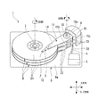
本実施形態の情報記録再生装置1は、図1に示すように、キャリッジ11と、キャリッジ11の基端側から光電気複合配線33を介して光束L(図6参照)を供給するレーザ光源20と、キャリッジ11の先端側に支持されたヘッドジンバルアセンブリ(HGA)12と、ヘッドジンバルアセンブリ12をディスク面D1(ディスクDの表面)に平行なXY方向に向けてスキャン移動させるアクチュエータ6と、ディスクDを所定の方向に向けて回転させるスピンドルモータ7と、情報に応じて変調した電流をヘッドジンバルアセンブリ12の記録ヘッド2に対して供給する制御部5と、これら各構成品を内部に収容するハウジング9と、を備えている。
(Information recording / reproducing device)
As shown in FIG. 1, the information recording / reproducing apparatus 1 of the present embodiment includes a
ハウジング9は、アルミニウム等の金属材料からなる上部開口部を有する箱型形状のものであり、上面視四角形状の底部9aと、底部9aの周縁において底部9aに対して鉛直方向に立設する周壁(不図示)とで構成されている。そして、周壁に囲まれた内側には、上述した各構成品を収容する凹部が形成される。
なお、図1においては、説明を分かりやすくするため、ハウジング9の周囲を取り囲む周壁を省略している。
The housing 9 has a box-like shape having a top opening made of a metal material such as aluminum, and has a
In FIG. 1, the peripheral wall surrounding the housing 9 is omitted for easy understanding.
ハウジング9には、該ハウジング9の上部開口部を塞ぐように図示しない蓋が着脱可能に固定されるようになっている。底部9aの略中心には、上記スピンドルモータ7が取り付けられており、該スピンドルモータ7に中心孔を嵌め込むことでディスクDが着脱自在に固定されている。
A lid (not shown) is detachably fixed to the housing 9 so as to close the upper opening of the housing 9. The
ディスクDの外側で、底部9aの一つの隅角部には、上述したアクチュエータ6が取り付けられている。このアクチュエータ6には、ピボット軸10を中心に水平面(XY方向)内で回動可能なキャリッジ11が取り付けられている。
このキャリッジ11は、基端部から先端部に向けて(ディスクD方向に向けて)延設されたアーム部14と、基端部を介してアーム部14を片持ち状に支持する基部15とが、削り出し加工等により一体形成されたものである。
基部15は、略直方体形状に形成されたものであり、ピボット軸10回りに回動可能に支持されている。つまり、基部15はピボット軸10を介してアクチュエータ6に連結されており、このピボット軸10がキャリッジ11の回転中心となっている。
The
The
The
アーム部14は、基部15におけるアクチュエータ6が取り付けられた側面15aと反対側の側面(隅角部の反対側の側面)15bにおいて、基部15の上面の面方向(XY方向)と平行に延出する平板状のものであり、基部15の高さ方向(Z方向)に沿って3枚延出している。
具体的には、アーム部14は、基端部から先端部に向かうにしたがって先細るテーパ形状に形成されており、各アーム部14間に、ディスクDが挟み込まれるように配置されている。つまり、アーム部14とディスクDとが、交互に配置可能に構成されており、アクチュエータ6の駆動によってアーム部14がディスク面D1に平行な方向(XY方向)に移動可能になっている。
なお、キャリッジ11及びヘッドジンバルアセンブリ12は、ディスクDの回転停止時にアクチュエータ6の駆動によって、ディスクD上から退避するようになっている。
The
Specifically, the
The
ヘッドジンバルアセンブリ12は、後述する記録ヘッド2にレーザ光源20からの光束Lを導いて近接場光S(図6参照)を発生させ、該近接場光Sを利用してディスクDに各種情報を記録再生させるものである。
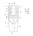
図2から図5に示すように、本実施形態のヘッドジンバルアセンブリ12は、上記記録ヘッド2をディスクDから浮上させる機能を有しており、該記録ヘッド2と、金属性材料により薄い板状に形成され、ディスク面D1に平行なXY方向に移動可能なサスペンション3と、記録ヘッド2をディスク面D1に平行で且つ互いに直交する2軸(X軸、Y軸)回りに回動自在な状態、即ち2軸を中心として捻れることができるようにサスペンション3の下面に固定させるジンバル手段16と、を備えている。
The
As shown in FIGS. 2 to 5, the
記録ヘッド2は、ディスクDとサスペンション3との間に配置された状態で、サスペンション3の下面に後述するジンバル17を挟んで支持されている。
図5及び図6に示すように、この記録ヘッド2は、ディスク面D1から所定距離だけ浮上した状態でディスクDに対向配置され、ディスク面D1に対向する浮上面2aを有するスライダ60と、スライダ60の流出端面(先端面)60a側に配設された、スポットサイズ変換器(光伝播素子)40、記録素子41、再生素子42及び近接場光発生素子43と、を備えている。
The
As shown in FIGS. 5 and 6, the
なお、記録ヘッド2は、スライダ60の流出端面60a側が最もディスク面D1に近接した状態でディスクD上を浮上する。従って、スライダ60の流出端面60a側に上記各構成品が配置されていることで、これらを可能な限りディスク面D1に近づけることができ、ディスクDの保磁力を効率良く低下させてディスクDへの書き込みが容易とされている。
The
ところで、本実施形態においては、スライダ60の流出端面60aにスポットサイズ変換器40が固定されており、記録素子41及び再生素子42がスポットサイズ変換器40の後述するクラッド51内に組み込まれた状態で配設されている。
具体的には、記録素子41及び再生素子42は、スライダ60の流出端面60aとスポットサイズ変換器40の後述する伝播部50との間に位置するようにクラッド51内に組み込まれている。この際、再生素子42がスライダ60の流出端面60aに固定され、この再生素子42に隣接して並ぶように記録素子41が固定されている。
By the way, in this embodiment, the
Specifically, the
スライダ60は、石英ガラス等の光透過性材料や、AlTiC(アルチック)等のセラミック等によって直方体状に形成されている。また、スライダ60は、浮上面2aをディスクD側に向けた状態で、ジンバル17(図3参照)を介してサスペンション3(図3参照)の先端にぶら下がるように支持されている。
The
再生素子42は、ディスクDから漏れ出ている磁界の大きさに応じて電気抵抗が変換する磁気抵抗効果膜である。この再生素子42には、後述する電気配線31を介して制御部5(図1参照)からバイアス電流が供給されている。これにより制御部5は、ディスクDから漏れ出た磁界の変化を電圧の変化として検出することでき、この電圧の変化から信号の再生を行うことが可能とされている。
The reproducing
記録素子41は、再生素子42側に位置する補助磁極45と、磁気回路46を介して補助磁極45に接続され、ディスクDに対して垂直な記録磁界を補助磁極45との間で発生させる主磁極47と、磁気回路46を中心として該磁気回路46の周囲を渦巻状に巻回されたコイル48とを備えている。
両磁極45、47及び磁気回路46は、磁束密度が高い高飽和磁束密度(Bs)材料(例えば、CoNiFe合金、CoFe合金等)により形成されている。また、コイル48は、ショートしないように、隣り合うコイル線間、磁気回路46との間、両磁極45、47との間に隙間が空くように配置されており、この状態で絶縁層49によってモールドされている。また、コイル48は情報に応じて変調された電流が制御部5から供給されるようになっている。
なお、主磁極47及び補助磁極45は、ディスクDに対向する端面がスライダ60の浮上面2aと面一となるように設計されている。
The
Both the
The main
スポットサイズ変換器40は、一端側から入射された光束Lをディスク面D1に向かう他端側に向けて集光しながら伝播させる伝播部50と、該伝播部50を内部に閉じ込めるクラッド51と、で構成される略板状の素子であって、上記したようにスライダ60の流出端面60aに固定されている。
The
伝播部50は、一端側がスライダ60の上方に向くと共に、他端側がディスクDに向いた状態で主磁極47の近傍に隣接している。そして、この伝播部50は、一端側から他端側に向かうにつれて、その長手方向(Z方向)に直交する断面積が漸次減少するように絞り成形されており、これにより光束Lを集光しながら伝播することが可能とされている。
また、伝播部50の他端側における端面は、スライダ60の浮上面2aに対して面一となるように設計されていると共に、主磁極47の近傍に位置している。そして、この伝播部50の端面上には、該伝播部50によって集光されながら伝播されてきた光束Lから近接場光Sを発生させる上記近接場光発生素子43が形成されている。
The
Further, the end face on the other end side of the
ここで上記伝播部50について、詳細に説明する。
本実施形態の伝播部50は、第1伝播部53及び第2伝播部54で一体的に構成されている。
第1伝播部53は、ディスクDに向かうにあたって、ディスクDの移動方向(Y方向)に沿い、且つ主磁極47から離間する方向に斜めに延在しており、一端側から入射された光束Lを、その入射方向とは異なる方向に曲げながら集光し、且つ該集光を行いながら主磁極47から離間する方向に伝播させている。
第2伝播部54は、この第1伝播部53に連結されると共に、ディスクDの移動方向(Y方向)に沿い、且つ主磁極47に接近する方向に斜めに延在しており、第1伝播部53によって伝播されてきた光束Lをさらに集光しながら主磁極47に接近する方向に曲げて伝播させ、端面上に形成された近接場光発生素子43に入射させている。
Here, the
The
The
The
なお、本実施形態では、第1伝播部53とは第2伝播部54とが、第1伝播部53から第2伝播部54に亘って直線的に折れ曲がるように連結されている。また、第1伝播部53及び第2伝播部54は、共にクラッド51の屈折率よりも高い屈折率の材料からなり、クラッド51との屈折率の違いから光束Lを全反射条件で導くコアとされている。
クラッド51は、コアである第1伝播部53及び第2伝播部54に密着して伝播部50を内部に閉じ込めている。
In the present embodiment, the
The clad 51 is in close contact with the
また、上記したように、第1伝播部53と第2伝播部54とはディスクDの移動方向に沿って折れ曲がるように連結されているので、クラッド51内における第1伝播部53と第2伝播部54との間にはスペースM(図6参照)が画成されている。そして、この画成されたスペースMを利用して記録素子41及び再生素子42が配設されている。
In addition, as described above, the
なお、クラッド51及びコアとして使用される材料の組み合わせの一例を記載すると、例えば、石英(SiO2)でコアを形成し、フッ素をドープした石英でクラッド51を形成する組み合わせが考えられる。この場合には、光束Lの波長が400nmのときに、コアの屈折率が1.47となり、クラッド51の屈折率が1.47未満となるので好ましい組み合わせである。また、ゲルマニウムをドープした石英でコアを形成し、石英(SiO2)でクラッド51を形成する組み合わせも考えられる。この場合には、光束Lの波長が400nmのときに、コアの屈折率が1.47より大きくなり、クラッド51の屈折率が1.47となるのでやはり好ましい組み合わせである。
An example of a combination of materials used as the
特に、コアとクラッド51との屈折率差が大きいほど、コア内に光束Lを閉じ込める力が大きくなるので、コアに酸化タンタル(Ta2O5:波長が550nmのときに屈折率が2.16)を用い、クラッド51に石英等を用いて、両者の屈折率差を大きくすることがより好ましい。また、赤外領域の光束Lを利用する場合には、赤外光に対して透明な材料であるシリコン(Si:屈折率が約4)でコアを形成することも有効である。
In particular, as the refractive index difference between the core and the clad 51 increases, the force confining the light beam L in the core increases, so that the tantalum oxide (Ta 2 O 5 : the refractive index is 2.16 when the wavelength is 550 nm). It is more preferable that the refractive index difference between the two is increased by using quartz or the like for the
近接場光発生素子43は、第2伝播部54によって伝播されてきた光束Lから近接場光Sを発生させる素子であり、例えば、第2伝播部54の端面上に形成された遮光膜と、該遮光膜に形成された微小開口と、で構成されている。この際、微小開口のサイズとしては、例えば直径数十nm〜数百nmの開口にすれば良い。こうすることで、第2伝播部54によって集光されながら伝播されてきた光束Lは、微小開口の通過時にスポットサイズがさらに小さくなって近接場光Sとなり、ディスクD側に出射される。
なお、近接場光発生素子43は、上記構成に限られるものではなく、例えばナノメートルサイズに形成された微小突起等であっても構わない。
The near-field
Note that the near-field
また、図2から図5に示すように、スライダ60の下面は、上述したようにディスク面D1に対向する浮上面2aとなっている。この浮上面2aは、回転するディスクDによって生じた空気流の粘性から、浮上するための圧力を発生させる面であり、ABS(AirBearing Surface)と呼ばれている。
具体的には、スライダ60をディスク面D1から離そうとする正圧とスライダ60をディスク面D1に引き付けようとする負圧とを調整して、スライダ60を最適な状態で浮上させるように設計されている。
スライダ60は、この浮上面2aによってディスク面D1から浮上する力を受けていると共に、サスペンション3によってディスクD側に押さえ付けられる力を受けている。そしてスライダ60は、この両者の力のバランスによって、ディスク面D1から浮上している。
As shown in FIGS. 2 to 5, the lower surface of the
Specifically, the
The
図2及び図3に示すように、サスペンション3は、上面視略四角状に形成されたベースプレート22と、ベースプレート22の先端側にヒンジ板23を介して連結された平面視略三角状のロードビーム24と、で構成されている。
As shown in FIGS. 2 and 3, the
ベースプレート22は、ステンレス等の厚みの薄い金属材料によって構成されており、基端側には厚さ方向に貫通する開口22aが形成されている。そして、この開口22aを介してベースプレート22がアーム部14の先端に固定されている。
ベースプレート22の下面には、ステンレス等の金属材料により構成されたシート状の上記ヒンジ板23が配置されている。このヒンジ板23は、ベースプレート22の下面の全面に亘って形成された平板状の板材であり、その先端部分はベースプレート22の先端からベースプレート22の長手方向に沿って延出する延出部23aとして形成されている。この延出部23aは、ヒンジ板23の幅方向両端部から2本延出しており、その先端部分にロードビーム24が連結されている。
The
On the lower surface of the
ロードビーム24は、ベースプレート22と同様にステンレス等の厚みの薄い金属材料によって形成されており、その基端がベースプレート22の先端との間に間隙を有した状態でヒンジ板23に連結されている。
これにより、サスペンション3は、ベースプレート22とロードビーム24との間を中心に屈曲して、ディスク面D1に垂直なZ方向に向けて撓み易くなっている。
The
As a result, the
また、サスペンション3上には、フレクシャ25が設けられている。
このフレクシャ25は、ステンレス等の金属材料により形成されたシート状のものであり、シート状に形成されることで厚さ方向に撓み変形可能に構成されている。また、このフレクシャ25は、ロードビーム24の先端側に固定され、外形が上面視略五角形状に形成されたジンバル17と、ジンバル17より幅狭に形成され、ジンバル17の基端からサスペンション3上に沿って延在する支持体18とで構成されている。
A
The
ジンバル17は、中間付近から先端にかけてディスク面D1に向けて厚さ方向に僅かながら反るように形成されている。そして、この反りが加わった先端側がロードビーム24に接触しないように、基端側から略中間付近にかけてロードビーム24に固定されている。また、この浮いた状態のジンバル17の先端側には、周囲がコ形状に刳り貫かれた切欠部26が形成されており、この切欠部26に囲まれた部分には連結部17aによって片持ち状に支持されたパッド部17bが形成されている。
つまり、このパッド部17bは、連結部17aによってジンバル17の先端側から基端側に向けて張出し形成されており、その周囲に切欠部26を備えている。
The
That is, the
これにより、パッド部17bはジンバル17の厚さ方向に撓みやすくなっており、このパッド部17bのみがサスペンション3の下面と平行になるように角度調整されている。そして、このパッド部17b上に上述した記録ヘッド2が載置固定されている。つまり、記録ヘッド2は、パッド部17bを介してロードビーム24にぶら下がった状態となっている。
Accordingly, the
また、図3及び図4に示すように、ロードビーム24の先端には、パッド部17b及び記録ヘッド2の略中心に向かって突出する突起部19が形成されている。この突起部19の先端は、丸みを帯びた状態となっている。そして突起部19は、記録ヘッド2がディスクDから受ける風圧によりロードビーム24側に浮上したときに、パッド部17bの表面(上面)に点接触するようになっている。
つまり、突起部19は、ジンバル17のパッド部17bを介して、記録ヘッド2を支持すると共に、ディスク面D1に向けて(Z方向に向けて)記録ヘッド2に荷重を付与するようになっている。そして、突起部19とパッド部17bとの接触点(支持点)が、突起部19による記録ヘッド2の荷重点になっている。
なお、これら突起部19とパッド部17bを有するジンバル17とが、ジンバル手段16を構成している。
As shown in FIGS. 3 and 4, a
That is, the
The
図2に示す支持体18は、ジンバル17に一体形成されたシート状のものであり、サスペンション3上をアーム部14に向かって延設されている。つまり、支持体18は、サスペンション3が変形した際にサスペンション3の変形に追従するように構成されている。また、この支持体18は、アーム部14上から側面に回りこんで、キャリッジ11の基部15に至るまで引き回されている。
The
図1及び図7に示すように、キャリッジ11の基部15における側面15cには、ターミナル基板30が配置されている。このターミナル基板30は、ハウジング9に設けられた制御部5と記録ヘッド2とを電気的に接続する際の中継点となるものであり、その表面には、各種制御回路(不図示)が形成されている。
制御部5とターミナル基板30とは、可撓性を有するフラットケーブル4により電気的に接続されている一方、ターミナル基板30と記録ヘッド2とは、電気配線31により接続されている。この電気配線31は、各キャリッジ11に設けられた記録ヘッド2に対応して3組設けられており、フラットケーブル4を介して制御部5から出力された信号が、電気配線31を介して記録ヘッド2に出力されるようになっている。
As shown in FIGS. 1 and 7, the
The
ターミナル基板30上には、記録ヘッド2のスポットサイズ変換器40に向けて光束Lを供給する上記レーザ光源20が配置されている。レーザ光源20は、フラットケーブル4を介して制御部5から出力された信号を受信し、この信号に基づいて光束Lを出射するものであり、各アーム部14に設けられた記録ヘッド2に対応して基部15の高さ方向(Z方向)に沿って3個配列されている。各レーザ光源20の出射側には、出射された光束Lを記録ヘッド2まで導く光導波路32が接続されている。
On the
図2及び図3に示すように、光導波路32と電気配線31とは、レーザ光源20と記録ヘッド2との間において、その基端側から先端に至るまで一体的に形成された光電気複合配線33として構成されている。
この光電気複合配線33は、ターミナル基板30の表面からアーム部14の側面を通って、アーム部14上に引き回されている。具体的には、光電気複合配線33は、アーム部14及びサスペンション3上において、フレクシャ25の支持体18上に配置されており、該支持体18を間に挟んだ状態でサスペンション3の先端まで引き回されている。
As shown in FIGS. 2 and 3, the
The photoelectric
そして、光電気複合配線33は、サスペンション3の先端、即ちジンバル17の中間位置において電気配線31と光導波路32とに分岐している。
具体的には、光導波路32は、光電気複合配線33の先端側における分岐地点からジンバル17の長手方向に沿って延在しており、ジンバル17の切欠部26を跨いで記録ヘッド2の流入端側に直接接続されている。光導波路32は、光電気複合配線33の分岐地点においてジンバル17の下面から離間されており、分岐地点から記録ヘッド2の流入端側に向かうにつれ、パッド部17bとジンバル17との間を架け渡すように僅かながら浮いた状態で延在している。
つまり、ジンバル17の下面において、光導波路32は略直線的(曲率半径が略無限大)に延在した状態で、記録ヘッド2の幅方向(X方向)中央部から記録ヘッド2の流入端側に引き回されている。
The photoelectric
Specifically, the
That is, on the lower surface of the
一方、上記分岐地点において、電気配線31はジンバル17の外周部分に向けて屈曲されており、ジンバル17の外周部分、つまり切欠部26の外側から引き回されている。そして、切欠部26の外側から引き回された電気配線31は、連結部17a上を通って記録ヘッド2の流出端面60a側に接続されている。即ち、電気配線31は、スライダ60の流出端面60a側に設けられた再生素子42と記録素子41とのそれぞれに対して、記録ヘッド2の外部から直接接続されている。
On the other hand, at the branch point, the
なお、光導波路32の構成材料は、上記したスポットサイズ変換器40のコア及びクラッド51と同様の材料を用いることも可能であるが、本実施形態では以下に示すような樹脂材料が好適に用いられている。
例えばPMMA(メタクリル酸メチル樹脂)により、厚さが3〜10μmでコア32aを形成し、フッ素含有重合体により、厚さが数十μmでクラッド32bを形成する組み合わせが考えられる。また、コア32a及びクラッド32bをともにエポキシ樹脂(例えば、コア屈折率1.522〜1.523、クラッド屈折率1.518〜1.519)で構成したり、フッ素化ポリイミドで構成したりすることも可能である。この場合、コア32aとクラッド32bとを構成する樹脂材料の配合等を調整して、両者の屈折率差を大きくすることが好ましい。例えば、フッ素化ポリイミドの場合、フッ素含有量を調整したり、放射光等のエネルギー照射によって、屈折率を制御したりすることができる。このように、光導波路32の構成材料に樹脂材料を用いることで、光電気複合配線33を半導体プロセスにより製造することが可能である。
The constituent material of the
For example, a combination in which the
ところで、図6に示すように、光導波路32の先端面は斜めにカットされたミラー面35とされており、レーザ光源20によって導入された光束Lを、該光束Lの向きが変わるように反射させている。これにより、ミラー面35で反射された光束Lが、記録ヘッド2のスポットサイズ変換器40を構成する伝播部50内に導入されるようになっている。なお、ミラー面35は、少なくともコア32aを含む領域にアルミ等からなる反射板を蒸着法等により形成するような構成としても構わない。
By the way, as shown in FIG. 6, the tip surface of the
(情報記録再生方法)
次に、このように構成された情報記録再生装置1により、ディスクDに各種の情報を記録再生する手順について説明する。
(Information recording and playback method)
Next, a procedure for recording and reproducing various types of information on the disc D by the information recording / reproducing apparatus 1 configured as described above will be described.
まず、スピンドルモータ7を駆動させてディスクDを所定方向に回転させる。次いで、アクチュエータ6を作動させて、ピボット軸10を回転中心としてキャリッジ11を回動させ、キャリッジ11を介してヘッドジンバルアセンブリ12をXY方向にスキャンさせる。これにより、図1に示すように、ディスクD上の所望する位置に記録ヘッド2を位置させることができる。
First, the
この際、記録ヘッド2は、サスペンション3によって支持されていると共に所定の力でディスクD側に押さえ付けられている。また、これと同時に記録ヘッド2は、浮上面2aを利用して、回転するディスクDによって生じる風圧の影響を受けて浮上する力を受けている。この両者の力のバランスによって、記録ヘッド2はディスクD上から離間した位置に浮上している。
しかも記録ヘッド2は、風圧を受けてサスペンション3側に押されるので、記録ヘッド2を固定するジンバル17のパッド部17bとサスペンション3に形成された突起部19とが、点接触した状態となる。そして、この浮上する力は、突起部19を介してサスペンション3に伝わり、該サスペンション3をディスク面D1に垂直なZ方向に向けて撓ませるように作用する。これにより、上記したように記録ヘッド2は浮上する。
At this time, the
Moreover, since the
ここで、情報の記録を行う場合、制御部5はレーザ光源20を作動させると共に、情報に応じて変調した電流をコイル48に供給して記録素子41を作動させる。
レーザ光源20が作動すると、光導波路32に光束Lを入射させる。すると、この光束Lは、光導波路32のコア32a内を先端側に向かって進んだ後、図6に示すように、ミラー面35で反射されてスポットサイズ変換器40の伝播部50内に入射する。伝播部50内に入射された光束Lは、第1伝播部53によってその入射方向とは異なる方向に曲げられながら、ディスクD側に位置する他端側に向かってクラッド51との界面との間で反射を繰り返しつつ、第1伝播部53及び第2伝播部54を順に伝播する。
Here, when recording information, the
When the
この際、伝播部50は一端側から他端側に向かうにしたがって絞り成形されているので、光束Lを徐々に集光しながら伝播させることができる。そのため光束Lは、徐々に絞り込まれて十分にスポットサイズが小さくなった状態で近接場光発生素子43に入射する。これにより、近接場光発生素子43は、効率良く近接場光Sを発生させることができ、外部に発することができる。すると、ディスクDはこの近接場光Sによって局所的に加熱されて一時的に保磁力が低下する。
At this time, since the
一方、制御部5によってコイル48に電流が供給されると、電磁石の原理により電流磁界が磁気回路46内に磁界を発生させるので、主磁極47と補助磁極45との間にディスクDに対して垂直方向の記録磁界を発生させることができる。
On the other hand, when a current is supplied to the
その結果、近接場光発生素子43で発生された近接場光Sと、記録素子41で発生された記録磁界とを協働させたハイブリッド磁気記録方式により情報の記録を行うことができる。しかも垂直記録方式で記録を行うので、熱揺らぎ現象等の影響を受け難く、安定した記録を行うことができる。よって、書き込みの信頼性を高めることができる。
As a result, information can be recorded by a hybrid magnetic recording method in which the near-field light S generated by the near-field
次に、ディスクDに記録された情報を再生する場合には、再生素子42がディスクDから漏れ出ている磁界を受けて、その大きさに応じて電気抵抗が変化する。よって、再生素子42の電圧が変化する。これにより制御部5は、ディスクDから漏れ出た磁界の変化を電圧の変化として検出することができる。そして制御部5は、この電圧の変化から信号の再生を行うことで、情報の再生を行うことができる。
上述したように、記録ヘッド2を利用してディスクDに対して各種の情報を記録再生することができる。
Next, when reproducing the information recorded on the disk D, the reproducing
As described above, various kinds of information can be recorded on and reproduced from the disk D using the
特に、本実施形態の記録ヘッド2によれば、伝播部50がクラッド51内に閉じ込められているので、伝播部50内を伝播される光束Lは外乱の影響を受け難い。しかも、この伝播部50は第1伝播部53及び第2伝播部54を有しており、第1伝播部53で光束Lを一旦主磁極47から遠ざけるように伝播させた後、第2伝播部54で主磁極47に近づけながら伝播させて近接場光発生素子43に入射させている。従って、光束Lを直線状に伝播するよりも伝播距離を稼ぐことができ、光束Lを効率良く集光することができる。
このように、外乱の影響を受け難いうえ、伝播距離を稼ぎながら効率良く光束Lを集光できるので、光伝播効率の低下を防ぐことができ、近接場光Sを効率良く発生させて書き込みの信頼性を高めることができる。
しかも、第1伝播部53及び第2伝播部54は共にコアであるので、光漏れ等による損失を抑制しながら光束Lを近接場光発生素子43まで確実に伝播可能である。この点においても、書き込みの信頼性の向上化を図ることができる。
In particular, according to the
In this way, it is difficult to be affected by disturbances, and the light flux L can be collected efficiently while increasing the propagation distance. Therefore, it is possible to prevent the light propagation efficiency from being lowered, and the near-field light S can be efficiently generated and written. Reliability can be increased.
Moreover, since both the
また、主磁極47に対して接近及び離間するように伝播部50の形状を設計できるので、設計上の制約を受け難く、スポットサイズ変換器40の設計の自由度を向上することができ、低コスト化に繋げることができる。
また、第1伝播部53に対して光束Lの入射方向がどのような方向から入射したとしても、第1伝播部53が該光束Lをその入射方向とは異なる方向に曲げながら、ディスクDの移動方向(Y方向)に沿い、且つ主磁極47から離間する方向に伝播させている。そのため、第1伝播部53に対する光束Lの入射方向が制約を受け難く、光導波路32の配置等、設計の自由度を向上させ易い。
Further, since the shape of the
In addition, no matter what direction the incident direction of the light beam L is incident on the
更に、第1伝播部53と第2伝播部54との間に画成されたクラッド51内のスペースMを利用して、記録素子41及び再生素子42を配設しているので、スポットサイズ変換器40、記録素子41及び再生素子42を単に一体化しただけなく、記録素子41及び再生素子42の厚みをスポットサイズ変換器40の厚みで吸収することが可能である。従って、記録ヘッド2全体の薄型化(コンパクト化)を図ることができる。
Further, since the
そして、本実施形態の情報記録再生装置1は、上述した記録ヘッド2を備えているので、書き込みの信頼性が高く、高密度記録化に対応した高品質な装置にすることができる。
Since the information recording / reproducing apparatus 1 of the present embodiment includes the
なお、本発明の技術範囲は上記実施の形態に限定されるものではなく、本発明の趣旨を逸脱しない範囲において種々の変更を加えることが可能である。 The technical scope of the present invention is not limited to the above embodiment, and various modifications can be made without departing from the spirit of the present invention.
例えば、上記実施形態では、スライダ60を浮上させた空気浮上タイプの情報記録再生装置1を例に挙げて説明したが、この場合に限られず、ディスク面D1に対向配置されていればディスクDとスライダ60とが接触していても構わない。つまり、本発明の記録ヘッド2は、コンタクトスライダタイプのヘッドであっても構わない。この場合であっても、同様の作用効果を奏することができる。
For example, in the above embodiment, the air floating type information recording / reproducing apparatus 1 in which the
また、上記実施形態では、アーム部14の片面側のみにヘッドジンバルアセンブリ12が設けられている構成について説明したが、各ディスクD間に差し入れられるアーム部14の両面に、各ディスクDに対向するようにそれぞれヘッドジンバルアセンブリ12を設けるような構成も可能である。
この場合には、アーム部14の両面側に設けられたヘッドジンバルアセンブリ12の各記録ヘッド2により、各記録ヘッド2に対向するディスク面D1の情報の記録再生を行うことができる。つまり、1つのアーム部14により2枚のディスクDの情報を記録再生することができるため、情報記録再生装置1の記録容量の増加及び装置の小型化を図ることができる。
In the above-described embodiment, the configuration in which the
In this case, information can be recorded / reproduced on the disk surface D1 facing each
また、上記実施形態では、スポットサイズ変換器40に光束Lを導入するレーザ光源20をキャリッジ11の基部15に取り付けられたターミナル基板30に配設させた構成としたが、この位置に限定されるものではない。例えば、スライダ60の上面に配設し、記録ヘッド2に一体的に搭載させても構わない。こうすることで、光導波路32をキャリッジ11から引き回す必要がないうえ、浮上時におけるスライダ60の動きが光導波路32によって阻害され難いので、より好ましい。
In the above embodiment, the
また、上記実施形態において、図8に示すように、第1伝播部53と第2伝播部54との連結部分を中心として、両伝播部53、54の側面に遮光膜70を形成すると良い。この遮光膜70は、高反射率の材料からなる膜、例えばアルミ膜とすれば良い。
このように遮光膜70を形成することで、第1伝播部53と第2伝播部54との連結部分から光束Lがより効果的に漏れ難くなる。従って、光漏れ等による損失を抑えることができ、光束Lをより効率良く伝播させて近接場光発生素子43に入射させることができる。従って、書き込みの信頼性をさらに高めることができる。
Moreover, in the said embodiment, as shown in FIG. 8, it is good to form the
By forming the
また、図9に示すように、第1伝播部53から第2伝播部54に亘って滑らかに湾曲するように、両伝播部53、54を連結させても構わない。この場合には、第1伝播部53と第2伝播部54との連結部分に角部が現れ難いので、上記遮光膜70を形成しなくても光束Lの光漏れ等が生じ難い。
従って、この場合であっても光束Lをより効率良く伝播させて近接場光発生素子43に入射させることができ、書き込みの信頼性をさらに高めることができる。
Further, as shown in FIG. 9, both
Therefore, even in this case, the light beam L can be propagated more efficiently and incident on the near-field
また、上記実施形態では、伝播部50の端面上に近接場光発生素子43を形成したが、主磁極47の近傍であれば端面上でなくても構わない。
例えば、図10に示すように、主磁極47上に成膜され、第2伝播部54から光束Lが入射された際に表面プラズモンを励起させることで近接場光Sを発生させる金属膜(例えば金膜等)71を近接場光発生素子としても構わない。
Further, in the above embodiment, the near-field
For example, as shown in FIG. 10, a metal film (for example, a film that is formed on the main
この場合には、第2伝播部54がディスクD側に向かうにつれて光束Lを主磁極47に接近させるように伝播させているので、該光束Lを金属膜71に対して所定の入射角度θを有するように斜めに入射させることができる。よって、第2伝播部54の傾きを変える等の容易な設計で、光束Lの入射角度θの調整を行うことができ、励起される表面プラズモン効率を変化させて近接場光Sの光強度調整を行うことが可能である。
従って、最適な光強度の近接場光Sを発生させることができ、書き込みの信頼性をより向上することができる。
In this case, since the light beam L is propagated so as to approach the main
Therefore, the near-field light S having the optimum light intensity can be generated, and the writing reliability can be further improved.
また、上記実施形態では、第1伝播部53及び第2伝播部54を共にコアとしたが、この場合に限られるものではない。
例えば、図11に示すように、第1伝播部53を上記実施形態と同様にコアで形成し、第2伝播部を、第1伝播部53によって伝播されてきた光束Lを近接場光発生素子43に向けて反射させる反射ミラー72としても構わない。
Moreover, in the said embodiment, although the
For example, as shown in FIG. 11, the
この場合には、主磁極47の近接に隣接するようにクラッド51に近接場光発生素子43を形成すれば良い。また、上記した金属膜71を主磁極47に形成し、この金属膜71を近接場光発生素子としても構わない。また、反射ミラー72は高反射率材料、例えばアルミ等を利用して形成すれば良い。
このように構成した場合であっても、第1伝播部53がコアであるので、光漏れ等による損失を抑制しながら光束Lを効率良く伝播することができると共に、反射ミラー72によってこの効率良く伝播された光束Lを反射させて、クラッド51内を進ませながら近接場光発生素子43に確実に入射させることができる。従って、書き込みの信頼性をさらに高めることができる。
なお、反射ミラー72は、単に第1伝播部53を伝播されてきた光束Lを反射させるだけでなく、集光させながら反射できるように形成することが好ましい。
In this case, the near-field
Even in such a configuration, since the
In addition, it is preferable to form the
また、上記実施形態では、記録素子41及び再生素子42を、伝播部50の第1伝播部53と第2伝播部54とで画成されたスペースMを利用してスポットサイズ変換器40のクラッド51内に配設させた構成としたが、この場合に限定されるものではない。
少なくとも記録素子41に関しては、スライダ60と伝播部50との間に配設されていれば良い。
In the above embodiment, the
At least the
例えば、図12に示すように、スライダ60の流出端面60a側から順に、再生素子42、記録素子41、スポットサイズ変換器40が並ぶように配置した記録ヘッド75としても構わない。
但し、上記実施形態のように再生素子42及び記録素子41が、スポットサイズ変換器40のクラッド51内に配設されている構成とすることで、再生素子42及び記録素子41の厚みをスポットサイズ変換器40の厚みで吸収できるので、記録ヘッドの薄型化を図り易く、好ましい。
For example, as shown in FIG. 12, a
However, since the reproducing
なお、上記各実施形態の記録ヘッド2、75を製造する場合には、フォトリソグラフィ技術及びエッチング加工技術等の半導体技術を利用して従来通りの工程で製造を行うことができる。つまり、ディスクDの移動方向に形状変化する伝播部50を有するスポットサイズ変換器40を備えている場合であっても、特別な手法を用いずに、従来の製造プロセスの流れの中でスポットサイズ変換器40も同時に作り込むことができる。
In the case of manufacturing the recording heads 2 and 75 of the above-described embodiments, the manufacturing can be performed by a conventional process using semiconductor technology such as photolithography technology and etching processing technology. That is, even when the
具体的に、図12に示す記録ヘッド75を製造する場合を例に挙げて説明する。
まず、図13(a)に示すように、後にスライダ60となるスライダ基板80の流出端面60a上に半導体技術を利用して再生素子42及び記録素子41を作り込む。次いで、図13(b)に示すように、後にスポットサイズ変換器40のクラッド51となるクラッド層81を積層した後、図13(c)に示すようにクラッド層81上にレジスト膜82を形成する。
Specifically, the case where the
First, as shown in FIG. 13A, the reproducing
次いで、図13(d)に示すように、レジスト膜82の一部にスポットサイズ変換器40の伝播部50のうち第2伝播部54を形成させるための第1窪み部83を形成する。この第1窪み部83の形成方法としては、型の押し付け(ホットエンボス)やグレースマスク露光等を行って形成すれば良い。次いで、図14(a)に示すように、RIE等の反応性イオンエッチング等を行って、この第1窪み部83をクラッド層81に転写させ、該クラッド層81に第1窪み部83を形成する。
Next, as shown in FIG. 13D, a
次いで、図14(b)に示すように、第1窪み部83が形成されたクラッド層81上に再度レジスト膜82を形成した後、図14(c)に示すように、該レジスト膜82の一部にスポットサイズ変換器40の伝播部50のうち第1伝播部53を形成させるための第2窪み部84を形成する。この第2窪み部84の形成方法としては、上記と同様である。
Next, as shown in FIG. 14B, a resist
次いで、図15(a)に示すように、RIE等の反応性イオンエッチング等を行って、この第2窪み部84をクラッド層81に転写させた後、先ほど形成した第1窪み部83を犠牲層85で覆う。更に、その後、犠牲層85及びクラッド層81の残りの部分を覆うように後に第1伝播部53となるコア層86を積層する。
Next, as shown in FIG. 15A, reactive ion etching such as RIE is performed to transfer the
次いで、図15(b)に示すように、上記コア層86を所定量研磨加工した後、犠牲層85をリフトオフする。これにより、第1伝播部53の一部(光束Lが入射する入射端から第2伝播部54との連結部分までの一部)が形成される。次いで、図15(c)に示すように、さらに全体にコア層86を積層した後、図16(a)に示すように、コア層86の一部にレジスト膜87を形成する。
Next, as shown in FIG. 15B, after the
次いで、図16(b)に示すように、上記レジスト膜87をマスクとしてRIE等の反応性イオンエッチング等を行い、コア層86を部分的に除去する。これにより、第1伝播部53及び第2伝播部54からなる伝播部50を形成することができる。次いで、図16(c)に示すように、全体に再度クラッド層81を積層した後、点線部分まで研磨加工を行うことで、図12に示すスポットサイズ変換器40を有する記録ヘッド75を製造することができる。
Next, as shown in FIG. 16B, reactive ion etching such as RIE is performed using the resist
このように、スライダ60の流出端面60a側から順に各構成品を作りこむ途中で、スポットサイズ変換器40の製造工程を一工程追加するだけで、容易に記録ヘッド75を製造することができる。なお、近接場光発生素子43に関しては、説明を省略したが上記工程中に同様の製造プロセスで作り込みを行えば良い。
As described above, the
また、上記実施形態において、第1伝播部又は第2伝播部を、少なくともその一部がレンズを有するように構成しても構わない。
例えば、第1伝播部そのものをレンズで構成する場合を例に挙げる。この場合には、図17及び図18に示すように、レンズとされた第1伝播部91及びコアからなる第2伝播部54で伝播部90が構成されている。第1伝播部91は、ディスクD側に向けて凸となった凸球面レンズであり、光導波路32のミラー面35で反射された光束Lが入射する位置に配設されている。また、この第1伝播部91は、凸球面部分における頂点位置P(図18参照)が球面中心ではなく、スライダ60の流出端面60aから離間する方向にシフトした凸球面状に形成されている。
Moreover, in the said embodiment, you may comprise a 1st propagation part or a 2nd propagation part so that at least one part may have a lens.
For example, the case where the 1st propagation part itself is comprised with a lens is mentioned as an example. In this case, as shown in FIGS. 17 and 18, a
そのため、第1伝播部91を利用して、光導波路32から入射された光束Lをその入射方向とは異なる方向に曲げ、且つ、主磁極47から離間する方向に集光させながら伝播させることが可能とされている。従って、この場合であっても同様の作用効果を奏効することができる。
Therefore, using the
なお、図示の例では、第1伝播部91そのものをレンズとしたが、例えば、第1伝播部をコアとレンズとの組み合わせで構成しても良い。いずれにしても、第1伝播部の少なくとも一部をレンズで構成しても構わない。また、第2伝播部についても、コアではなくレンズとしても構わないし、さらにはコアに代えて反射ミラーとしても構わない。
In the illustrated example, the
また、上記実施形態では、第1伝播部53が光導波路32から入射された光束Lを、入射方向とは異なる方向に曲げながら集光及び伝播させる構成としたが、例えば、図19に示すように、光導波路32のミラー面35の角度θを鋭角(例えば45度以下)とし、光束Lの向きをディスクDの移動方向(Y方向)に沿い、且つ主磁極47から離間する方向に一致させた状態で、第1伝播部53に入射するように構成しても構わない。
この場合、第1伝播部53は、光束Lの向きを変化させることなく、引き続きディスクDの移動方向(Y方向)に沿い、且つ主磁極47から離間する方向に向けて、集光及び伝播させる。そのため、光エネルギーの損失をできるだけ抑制しながら光束Lを効率良く伝播させ易い。この場合であっても、同様の作用効果を奏効することができる。
In the above embodiment, the
In this case, the
なお、この場合において、第1伝播部53及び第2伝播部54を共にコアとするのではなく、例えば、図20に示すように、第1伝播部95をディスクD側に向けて凸となった凸球面のレンズとし、第2伝播部96を反射ミラーとした構成としても構わない。この場合であっても同様の作用効果を奏効することができる。なお、この場合には、第1伝播部95及び第2伝播部96をクラッドではなく誘電体97の内部に埋設されるように構成すれば良い。
In this case, the
L…光束
D…ディスク(磁気記録媒体)
D1…ディスク面(磁気記録媒体の表面)
1…情報記録再生装置
2、75…記録ヘッド
3…サスペンション
20…レーザ光源(光源)
10…ピボット軸
11…キャリッジ
14…アーム部
40…スポットサイズ変換器(光伝播素子)
41…記録素子
43…近接場光発生素子
47…主磁極
50、90…伝播部
51…クラッド
53、91、95…第1伝播部
54、96…第2伝播部
60…スライダ
60a…スライダの流出端面
71…金属膜(近接場光発生素子)
72…反射ミラー(第2伝播部)
L ... Light flux D ... Disk (magnetic recording medium)
D1 ... disk surface (surface of magnetic recording medium)
DESCRIPTION OF SYMBOLS 1 ... Information recording / reproducing
DESCRIPTION OF
DESCRIPTION OF
72: Reflection mirror (second propagation part)
Claims (7)
該スライダの流出端面側に配設され、入射された光束を前記磁気記録媒体の表面に向けて集光しながら伝播させる伝播部を有する光伝播素子と、
前記スライダの流出端面と前記伝播部との間に配設され、記録磁界を発生させる主磁極を有する記録素子と、
前記主磁極の近傍に配設され、前記伝播部によって伝播されてきた前記光束から近接場光を発生させる近接場光発生素子と、を備え、
前記伝播部及び前記主磁極は、前記磁気記録媒体の表面に垂直な方向、及び前記磁気記録媒体の移動方向の2方向で画成される同一の面に沿って配置され、
前記伝播部は、
前記光束が進むにつれて前記光束を、前記面内において前記主磁極から離間する方向に伝播させる第1伝播部と、
前記第1伝播部で伝播されてきた前記光束を、前記面内において前記主磁極に接近する方向に伝播させると共に、前記近接場光発生素子に入射させる第2伝播部と、を備えていることを特徴とする記録ヘッド。 A slider having an outflow end face disposed in a direction orthogonal to the moving direction of the magnetic recording medium, and disposed opposite to the surface of the magnetic recording medium rotating in a certain direction;
A light propagation element disposed on the outflow end face side of the slider and having a propagation part that propagates the incident light beam while condensing it toward the surface of the magnetic recording medium;
A recording element that is disposed between the outflow end face of the slider and the propagation part and has a main magnetic pole for generating a recording magnetic field;
A near-field light generating element disposed in the vicinity of the main magnetic pole and generating near-field light from the light flux propagated by the propagation part,
The propagation part and the main magnetic pole are arranged along the same plane defined in two directions, a direction perpendicular to the surface of the magnetic recording medium and a moving direction of the magnetic recording medium,
The propagation part is
A first propagation part that propagates the light beam in a direction away from the main magnetic pole in the plane as the light beam travels;
A second propagating section for propagating the light beam propagated by the first propagating section in a direction approaching the main magnetic pole in the plane and entering the near-field light generating element. A recording head characterized by.
前記記録素子は、前記第1伝播部と前記第2伝播部との間に画成されたスペースに配設されていることを特徴とする記録ヘッド。 The recording head according to claim 1,
The recording head, wherein the recording element is disposed in a space defined between the first propagation unit and the second propagation unit.
前記近接場光発生素子は、前記主磁極上に成膜され、前記第2伝播部から前記光束が入射された際に表面プラズモンの励起により前記近接場光を発生させる金属膜であり、
前記第2伝播部は、前記近接場光発生素子に対して斜めに入射するように前記光束を伝播していることを特徴とする記録ヘッド。 The recording head according to claim 1 or 2,
The near-field light generating element is a metal film that is formed on the main magnetic pole and generates the near-field light by excitation of surface plasmons when the light beam is incident from the second propagation part.
The recording head, wherein the second propagation unit propagates the light flux so as to be incident obliquely on the near-field light generating element.
前記光伝播素子は、前記伝播部を内部に閉じ込めるクラッドを備えていることを特徴とする記録ヘッド。 The recording head according to any one of claims 1 to 3,
The recording head according to claim 1, wherein the light propagation element includes a clad for confining the propagation part.
前記第1伝播部及び前記第2伝播部は、前記クラッドの屈折率よりも高い屈折率を有する材料で形成され、前記光束を全反射条件で導くコアであることを特徴とする記録ヘッド。 The recording head according to claim 4, wherein
The recording head, wherein the first propagation part and the second propagation part are formed of a material having a refractive index higher than a refractive index of the cladding, and are cores that guide the light beam under total reflection conditions.
前記第1伝播部は、前記クラッドの屈折率よりも高い屈折率を有する材料で形成され、前記光束を全反射条件で導くコアであり、
前記第2伝播部は、前記第1伝播部によって伝播されてきた前記光束を前記近接場光発生素子に向けて反射させる反射ミラーであることを特徴とする記録ヘッド。 The recording head according to claim 4, wherein
The first propagation part is a core that is formed of a material having a refractive index higher than that of the cladding and guides the light flux under a total reflection condition.
The recording head, wherein the second propagation unit is a reflection mirror that reflects the light beam propagated by the first propagation unit toward the near-field light generating element.
前記磁気記録媒体の表面に平行な方向に移動可能とされ、該磁気記録媒体の表面に平行で且つ互いに直交する2軸回りに回動自在な状態で前記記録ヘッドを支持するサスペンションと、
前記伝播部に前記光束を入射させる光源と、
前記磁気記録媒体の外側に配置されたピボット軸と、
該ピボット軸の回りを回転可能に形成されると共に、前記サスペンションを支持するアーム部を有するキャリッジと、を備えていることを特徴とする情報記録再生装置。 The recording head according to any one of claims 1 to 6,
A suspension that is movable in a direction parallel to the surface of the magnetic recording medium, and that supports the recording head in a state of being rotatable about two axes parallel to the surface of the magnetic recording medium and orthogonal to each other;
A light source that causes the light beam to enter the propagation portion;
A pivot shaft disposed outside the magnetic recording medium;
An information recording / reproducing apparatus comprising: a carriage formed to be rotatable around the pivot shaft and having an arm portion for supporting the suspension.
Priority Applications (1)
| Application Number | Priority Date | Filing Date | Title |
|---|---|---|---|
| JP2014125813A JP6029185B2 (en) | 2014-06-18 | 2014-06-18 | Recording head and information recording / reproducing apparatus |
Applications Claiming Priority (1)
| Application Number | Priority Date | Filing Date | Title |
|---|---|---|---|
| JP2014125813A JP6029185B2 (en) | 2014-06-18 | 2014-06-18 | Recording head and information recording / reproducing apparatus |
Related Parent Applications (1)
| Application Number | Title | Priority Date | Filing Date |
|---|---|---|---|
| JP2011211287A Division JP5740769B2 (en) | 2011-09-27 | 2011-09-27 | Recording head and information recording / reproducing apparatus |
Publications (2)
| Publication Number | Publication Date |
|---|---|
| JP2014167843A JP2014167843A (en) | 2014-09-11 |
| JP6029185B2 true JP6029185B2 (en) | 2016-11-24 |
Family
ID=51617449
Family Applications (1)
| Application Number | Title | Priority Date | Filing Date |
|---|---|---|---|
| JP2014125813A Expired - Fee Related JP6029185B2 (en) | 2014-06-18 | 2014-06-18 | Recording head and information recording / reproducing apparatus |
Country Status (1)
| Country | Link |
|---|---|
| JP (1) | JP6029185B2 (en) |
Family Cites Families (6)
| Publication number | Priority date | Publication date | Assignee | Title |
|---|---|---|---|---|
| JP4254780B2 (en) * | 2005-12-16 | 2009-04-15 | Tdk株式会社 | Thin film magnetic head having near-field light generating layer, head gimbal assembly having the same, and magnetic disk drive |
| JPWO2007132766A1 (en) * | 2006-05-16 | 2009-09-24 | コニカミノルタオプト株式会社 | Optical recording head, magneto-optical recording head, and optical recording apparatus |
| JP5278887B2 (en) * | 2006-11-20 | 2013-09-04 | セイコーインスツル株式会社 | Near-field optical head and information recording / reproducing apparatus |
| JP5201571B2 (en) * | 2006-11-20 | 2013-06-05 | セイコーインスツル株式会社 | Recording head and information recording / reproducing apparatus |
| JP2009140538A (en) * | 2007-12-04 | 2009-06-25 | Seiko Instruments Inc | Recording head and information recording/reproduction device |
| JP2010123169A (en) * | 2008-11-18 | 2010-06-03 | Fujitsu Ltd | Magnetic head, magnetic recorder, and method of manufacturing magnetic head |
-
2014
- 2014-06-18 JP JP2014125813A patent/JP6029185B2/en not_active Expired - Fee Related
Also Published As
| Publication number | Publication date |
|---|---|
| JP2014167843A (en) | 2014-09-11 |
Similar Documents
| Publication | Publication Date | Title |
|---|---|---|
| JP5278887B2 (en) | Near-field optical head and information recording / reproducing apparatus | |
| JP5201571B2 (en) | Recording head and information recording / reproducing apparatus | |
| JP5804487B2 (en) | RECORDING HEAD, RECORDING HEAD MANUFACTURING METHOD, AND INFORMATION RECORDING / REPRODUCING DEVICE | |
| JP5841313B2 (en) | Near-field optical head and information recording / reproducing apparatus | |
| JP5441184B2 (en) | Head gimbal assembly and information recording / reproducing apparatus including the same | |
| JP5943417B2 (en) | Near-field light generating element, near-field light head, and information recording / reproducing apparatus | |
| JP5039893B2 (en) | Recording head and information recording / reproducing apparatus | |
| JP2009140538A (en) | Recording head and information recording/reproduction device | |
| JP6029185B2 (en) | Recording head and information recording / reproducing apparatus | |
| JP5740769B2 (en) | Recording head and information recording / reproducing apparatus | |
| JP5550048B2 (en) | Recording head and information recording / reproducing apparatus | |
| JP5692797B2 (en) | Near-field optical element, recording head, information recording / reproducing apparatus, manufacturing method of near-field optical element, and manufacturing method of recording head | |
| JP5550049B2 (en) | Recording head and information recording / reproducing apparatus | |
| JP5780630B2 (en) | Recording head and information recording / reproducing apparatus | |
| JP5823895B2 (en) | Manufacturing method of head using near-field light | |
| JP5804718B2 (en) | Recording head and information recording / reproducing apparatus | |
| JP5692724B2 (en) | Near-field light generating element manufacturing method, near-field light generating element, near-field light head, and information recording / reproducing apparatus | |
| JP5729716B2 (en) | Recording head manufacturing method, recording head, and information recording / reproducing apparatus | |
| JP5200273B2 (en) | Head gimbal assembly and information recording / reproducing apparatus including the same | |
| WO2009154043A1 (en) | Head gimbal assembly with optical guide structure, and information recording/reproducing device | |
| JP2010123226A (en) | Near field light head and information recording and reproducing device | |
| JP6066656B2 (en) | Near-field light utilization head and information recording / reproducing apparatus including the same | |
| WO2008062677A1 (en) | Recording head and information recording/reproducing device | |
| JP2009099212A (en) | Recording head and information recording/reproducing device | |
| JP2010086624A (en) | Head gimbal assembly with light guide structure, and information recording and reproducing apparatus |
Legal Events
| Date | Code | Title | Description |
|---|---|---|---|
| A621 | Written request for application examination |
Free format text: JAPANESE INTERMEDIATE CODE: A621 Effective date: 20140618 |
|
| A977 | Report on retrieval |
Free format text: JAPANESE INTERMEDIATE CODE: A971007 Effective date: 20150708 |
|
| A131 | Notification of reasons for refusal |
Free format text: JAPANESE INTERMEDIATE CODE: A131 Effective date: 20150804 |
|
| A131 | Notification of reasons for refusal |
Free format text: JAPANESE INTERMEDIATE CODE: A131 Effective date: 20160315 |
|
| A521 | Written amendment |
Free format text: JAPANESE INTERMEDIATE CODE: A523 Effective date: 20160511 |
|
| TRDD | Decision of grant or rejection written | ||
| A01 | Written decision to grant a patent or to grant a registration (utility model) |
Free format text: JAPANESE INTERMEDIATE CODE: A01 Effective date: 20160927 |
|
| RD03 | Notification of appointment of power of attorney |
Free format text: JAPANESE INTERMEDIATE CODE: A7423 Effective date: 20161013 |
|
| A61 | First payment of annual fees (during grant procedure) |
Free format text: JAPANESE INTERMEDIATE CODE: A61 Effective date: 20161013 |
|
| R150 | Certificate of patent or registration of utility model |
Ref document number: 6029185 Country of ref document: JP Free format text: JAPANESE INTERMEDIATE CODE: R150 |
|
| LAPS | Cancellation because of no payment of annual fees |