JP6026875B2 - Vaporization monitoring system and monitoring method for solid materials - Google Patents
Vaporization monitoring system and monitoring method for solid materials Download PDFInfo
- Publication number
- JP6026875B2 JP6026875B2 JP2012264378A JP2012264378A JP6026875B2 JP 6026875 B2 JP6026875 B2 JP 6026875B2 JP 2012264378 A JP2012264378 A JP 2012264378A JP 2012264378 A JP2012264378 A JP 2012264378A JP 6026875 B2 JP6026875 B2 JP 6026875B2
- Authority
- JP
- Japan
- Prior art keywords
- solid material
- container
- pressure
- gas
- concentration
- Prior art date
- Legal status (The legal status is an assumption and is not a legal conclusion. Google has not performed a legal analysis and makes no representation as to the accuracy of the status listed.)
- Active
Links
Images


Description
本発明は、固体材料の気化量モニタリングシステムおよびモニタリング方法に関し、例えば、固体材料を用いて半導体や太陽電池等の生産装置や研究設備等において使用される材料ガスや各種プロセスにおいて使用される特殊ガス等のガス供給装置において、蒸発または昇華された固体材料の気化量をモニタリングするシステムおよびモニタリング方法に関するものである。なお、本願にいう「固体材料」とは、広く工業的に用いられるキャリアガスにより所定量の蒸発または昇華(気化)・供給が可能な固体材料をいい、例えば、塩化ハフニウム等の無機金属化合物、トリメチルインジウム等の固体有機金属化合物、ピロメリット酸二無水物やアントラキノンあるいはフタル酸等のような固体有機化合物、または塩化アルミニウム等の固体無機化合物等を挙げることができる。 The present invention relates to a solid material vaporization monitoring system and monitoring method, for example, a material gas used in a production apparatus or research facility such as a semiconductor or a solar cell using a solid material, or a special gas used in various processes. The present invention relates to a system and a monitoring method for monitoring the amount of vaporized or sublimated solid material in a gas supply apparatus such as the above. As used herein, the term “solid material” refers to a solid material that can be evaporated or sublimated (vaporized) / supplied by a carrier gas widely used industrially, for example, an inorganic metal compound such as hafnium chloride, Examples thereof include solid organometallic compounds such as trimethylindium, solid organic compounds such as pyromellitic dianhydride, anthraquinone and phthalic acid, and solid inorganic compounds such as aluminum chloride.
半導体や太陽電池等を生産する製造装置や新たな素材を開発する研究設備、あるいは高純度品が要求される半導体の材料等(例えば成膜材料等)として、気体材料や液体材料が多用されてきたが、近年では、蒸発または昇華させた上記のような固体材料をキャリアガスに同伴させて使用することも多い。こうした固体材料は、ヘリウムやアルゴン等の希ガス等の反応性が低く安定性の高い不活性ガスによって蒸発または昇華・搬送されたガス(以下「固体成分ガス」という)、上記製造装置等に供給されて消費される。 Gas materials and liquid materials have been widely used as manufacturing equipment for producing semiconductors, solar cells, etc., research equipment for developing new materials, or semiconductor materials that require high-purity products (for example, film-forming materials). However, in recent years, the above solid materials evaporated or sublimated are often used with carrier gas. Such a solid material is supplied to a gas (hereinafter referred to as “solid component gas”) evaporated or sublimated and transported by an inert gas having low reactivity and high stability such as a rare gas such as helium or argon, and the above-described manufacturing apparatus. Being consumed.
こうした固体材料は、従前より蒸発または昇華速度が遅いこと、安定した蒸発または昇華が難しく気化量が安定しないこと、精製された固体材料の入手が困難で固体成分ガスが限定されること等の課題があったが、利用範囲の拡大や関連技術の進歩により、安定した固体材料ガスの供給に関し、種々の検討がなされてきた。 Such solid materials have problems such as a slower evaporation or sublimation rate than before, stable evaporation or sublimation is difficult and the amount of vaporization is not stable, and it is difficult to obtain a purified solid material and the solid component gas is limited. However, due to the expansion of the range of use and the advancement of related technologies, various studies have been made on the stable supply of solid material gas.
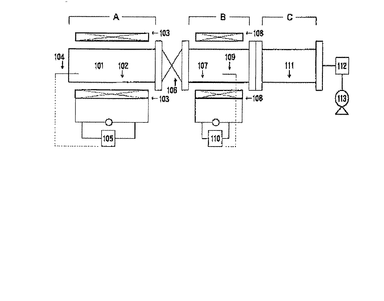
例えば、微量から多量の供給原料を均一にしかも短時間に加熱すると共に、その加熱温度を精度高く制御でき、それによって熱安定性に乏しい固体材料を効率よく昇華精製する方法及び装置を提供することを目的として、図4に示すような昇華精製装置が提案されている(例えば特許文献1参照)。具体的には、昇華部Aの筒状の金属材料102の1層が磁性金属材料であり、外周には電磁誘導式で発熱させる誘導コイル103を有し、昇華部の下流側には温度の異なる複数のゾーンを有する捕集部B、Cが設けられ、1つのゾーンは筒状の金属材料の1層が磁性金属材料であり、外周には電磁誘導式で発熱させる誘導コイル108とを有し、昇華部と捕集部との間には下流側に向かって温度がほぼ階段状に低下する温度勾配を設けてなる装置である。ここで、101は昇華室、104,109は熱電対、105,110は温度調節計、106はバタフライ弁、107,111は筒状体、112はトラップ、113は真空ポンプを示す。
For example, to provide a method and an apparatus for heating a solid material having a low thermal stability efficiently by sublimating and purifying a solid material having a low thermal stability while heating a minute amount of a large amount of feedstock uniformly and in a short time. For this purpose, a sublimation purification apparatus as shown in FIG. 4 has been proposed (see, for example, Patent Document 1). Specifically, one layer of the
しかし、上記のような昇華精製方法や昇華精製装置あるいは固体材料ガスの供給装置や供給方法においては、以下の課題が生じることがあった。
(i)固体材料のキャリアガスによる均一な昇華・供給には、上記のような昇華温度の制御だけではなく、常態として粉状または顆粒状であることから、固体材料の偏在や粉体あるいは粒子からの蒸発または昇華速度のばらつきによる気化量の変動があった。その結果、実際の固体材料ガスの供給において、固体材料ガス中の供給成分濃度(以下「材料濃度」という)の安定性を確保することが困難であった。
(ii)固体材料の残量は、材料濃度に大きな影響を与えるだけではなく、使用によって変化する固体材料の形状や形態が材料濃度に大きな影響を与える。特に、粉状または顆粒状の固体材料にあっては、所定の残量があっても、その表面でのキャリアガスとの接触状態の変化等から十分な材料濃度を得ることできないことがあることが判った。
(iii)また、固体材料ガスの供給装置が設置された上記のような半導体等の製造プロセスでは、材料濃度が最終製品に大きな影響を与えることから、インラインでの材料濃度の管理が必要となり、材料濃度の検出には、非常に高い精度,信頼性と安定性が要求される。
However, in the above-described sublimation purification method, sublimation purification device, or solid material gas supply device or supply method, the following problems may occur.
(I) For uniform sublimation and supply of a solid material by a carrier gas, not only the control of the sublimation temperature as described above but also a powder or granule in the normal state. There were fluctuations in the amount of vaporization due to variations in evaporation or sublimation rate. As a result, in the actual supply of the solid material gas, it is difficult to ensure the stability of the supply component concentration (hereinafter referred to as “material concentration”) in the solid material gas.
(Ii) The remaining amount of the solid material not only greatly affects the material concentration, but also the shape and form of the solid material that changes depending on the use greatly affects the material concentration. In particular, in the case of powdered or granular solid materials, even if there is a predetermined remaining amount, it may not be possible to obtain a sufficient material concentration due to changes in the contact state with the carrier gas on the surface, etc. I understood.
(Iii) In addition, in the manufacturing process of semiconductors and the like as described above in which a solid material gas supply device is installed, since the material concentration has a great influence on the final product, it is necessary to manage the material concentration in-line. The detection of material concentration requires very high accuracy, reliability and stability.
本発明の目的は、固体材料ガスの供給装置において、簡便な手法・構成で、高い精度と信頼性および安定性の高い材料濃度の検出ができる固体材料の気化量モニタリングシステムおよびモニタリング方法を提供することにある。また、これらを用い、安定した濃度で固体材料ガスを供給することができる固体材料ガスの供給装置を提供することにある。 An object of the present invention is to provide a solid material vaporization monitoring system and a monitoring method capable of detecting a material concentration with high accuracy, reliability, and stability with a simple method and configuration in a solid material gas supply apparatus. There is. Another object of the present invention is to provide a solid material gas supply device that can use these to supply a solid material gas at a stable concentration.
本発明者らは、上記課題を解決するために鋭意研究を重ねた結果、以下に示す固体材料の気化量モニタリングシステム,モニタリング方法およびこれらを用いた固体材料ガスの供給装置によって上記目的を達成できることを見出し、本発明を完成するに到った。 As a result of intensive studies to solve the above problems, the present inventors can achieve the above object by the following solid material vaporization monitoring system, monitoring method, and solid material gas supply device using them. As a result, the present invention has been completed.
本発明は、固体材料の気化量モニタリングシステムであって、
固体材料が配設される加熱可能な所定容量を有する容器と、該容器へのキャリアガスの供給を担うキャリアガス供給部と、固体材料を同伴した固体材料ガスの該容器からの供出を担う固体材料ガス供出部と、該容器内部を脱気し減圧状態とする減圧処理部と、該容器内部の圧力を検出する圧力検出器と、前記固体材料ガス供出部から供出される固体材料ガス中の供給成分濃度を検出する濃度検出器と、少なくとも前記圧力検出器および濃度検出器からの出力が入力され演算処理を行う演算部と、を備え、
予め減圧条件下において所定温度に加熱された前記容器内の固体材料から蒸発または昇華したガス成分の蒸気圧を前記圧力検出器によって検出し、所定流量のキャリアガスが導入された加熱状態の前記容器から供出される固体材料ガス中の供給成分の濃度を濃度検出器によって検出し、前記蒸気圧およびキャリアガスの流量から下式1に基づき固体材料の気化量を算出するとともに、
固体材料の気化量=(固体材料の飽和蒸気圧/全圧)×(キャリアガスの流量)×(固体材料の分子量)・・・式1
予め所定の容器内温度,所定のキャリアガス流量条件下における容器内の圧力−供給成分の濃度−固体材料の気化量の相関を設定し、
所定温度に加熱された前記容器にキャリアガスが供給された固体材料ガスの供給状態において、検出された前記容器内の圧力と検出された前記供給成分の濃度から前記固体材料の気化量を算出することを特徴とする。
The present invention is a solid material vaporization monitoring system comprising:
A container having a predetermined capacity capable of being heated, in which a solid material is disposed, a carrier gas supply unit that is responsible for supplying carrier gas to the container, and a solid that is responsible for delivering the solid material gas accompanying the solid material from the container In the solid material gas supplied from the material gas supply part, the pressure reduction processing part for degassing the inside of the container to make the pressure reduced, the pressure detector for detecting the pressure inside the container, and the solid material gas supply part A concentration detector that detects a supply component concentration, and an arithmetic unit that receives at least outputs from the pressure detector and the concentration detector and performs arithmetic processing;
The container in a heated state in which a vapor pressure of a gas component evaporated or sublimated from a solid material in the container previously heated to a predetermined temperature under a reduced pressure condition is detected by the pressure detector and a carrier gas having a predetermined flow rate is introduced. The concentration of the supply component in the solid material gas delivered from is detected by a concentration detector, and the vaporization amount of the solid material is calculated from the vapor pressure and the flow rate of the carrier gas based on the following formula 1.
Vaporization amount of solid material = (saturated vapor pressure / total pressure of solid material) × (flow rate of carrier gas) × (molecular weight of solid material) Equation 1
A correlation between the pressure in the container under the predetermined container temperature and the predetermined carrier gas flow rate, the concentration of the supply component, and the vaporization amount of the solid material is set in advance.
In the supply state of the solid material gas in which the carrier gas is supplied to the container heated to a predetermined temperature, the vaporization amount of the solid material is calculated from the detected pressure in the container and the detected concentration of the supply component. It is characterized by that.
固体材料を蒸発または昇華させて固体材料ガスを供給することには、上記のように、材料濃度の安定性等いくつかの課題があった。本発明は、固体材料の昇華による固体材料ガスの供給において、予め固体材料の気化量に影響を与える要素(容器内の温度・圧力、キャリアガスの流量等の変動要素)と気化量との相関を設定し、気化量と高い相関を有する固体材料ガス中の供給成分の濃度(材料濃度)を基に気化量を算出することによって、非常に精度の高い固体材料の気化量をモニタリングすることができ、こうした課題を解消することができることを見出したものである。つまり、気化量という安定したモニターが難しい物理量を、その変動の発生要因となる上記変動要素と変動した結果である材料濃度を指標とすることによって、より正確な気化量の把握を可能とした。具体的には、予め基準となる減圧条件を含む安定的な特定条件下で固体材料を蒸発または昇華させ、そのときの上記変動要素と材料濃度の相関関係を求め、その設定条件を基に実動条件での変動要素を指標として気化量を算出することによって、信頼性の高い気化量を得ることができる。このように、簡便な手法・構成で、高い精度と信頼性および安定性の高い材料濃度の検出ができる固体材料の気化量モニタリングシステムを提供することが可能となった。また、このシステムを用いることによって、安定した濃度で固体材料ガスを供給することができる固体材料ガスの供給装置を構成することが可能となった。
ここで、前記固体材料ガス中の供給成分の濃度およびキャリアガスの流量を監視し、予め求めた固体試料の残量と固体材料ガス中の供給成分の濃度との関係を基に、固体材料の残量を管理することが好ましい。固体材料Sの残量が所定量以下となり、気化された固体材料の総量だけではなく残量自体および固体材料Sの形状や形態等(性状)によって、材料濃度の低下を招来することがないように、得られた固体試料Sの残量情報を利用して、キャリアガスCの流量を調整することによって、安定した材料濃度を有する固体材料ガスGを供給することができる。
Supplying the solid material gas by evaporating or sublimating the solid material has some problems such as the stability of the material concentration as described above. In the present invention, in the supply of a solid material gas by sublimation of a solid material, the correlation between the vaporization amount and factors that affect the vaporization amount of the solid material in advance (variable factors such as the temperature / pressure in the container and the flow rate of the carrier gas) The amount of vaporization of the solid material can be monitored with high accuracy by calculating the amount of vaporization based on the concentration (material concentration) of the supply component in the solid material gas having a high correlation with the amount of vaporization. It has been found that these problems can be solved. In other words, the physical quantity, which is difficult to monitor stably, such as the amount of vaporization, can be obtained more accurately by using the above-mentioned fluctuation factors that cause the fluctuation and the material concentration as a result of the fluctuation as an index. Specifically, the solid material is evaporated or sublimated under stable specific conditions including the reference decompression condition in advance, and the correlation between the above-mentioned variation factor and the material concentration at that time is obtained, and based on the set conditions, A highly reliable vaporization amount can be obtained by calculating the vaporization amount using a variable element under dynamic conditions as an index. As described above, it is possible to provide a vaporization amount monitoring system for a solid material that can detect a material concentration with high accuracy, reliability, and stability with a simple method and configuration. Also, by using this system, it has become possible to configure a solid material gas supply device that can supply solid material gas at a stable concentration.
Here, the concentration of the supply component in the solid material gas and the flow rate of the carrier gas are monitored, and based on the relationship between the remaining amount of the solid sample obtained in advance and the concentration of the supply component in the solid material gas, It is preferable to manage the remaining amount. The remaining amount of the solid material S becomes a predetermined amount or less, so that not only the total amount of the solidified vaporized material but also the remaining amount itself and the shape, form, etc. (properties) of the solid material S do not cause a decrease in the material concentration. In addition, the solid material gas G having a stable material concentration can be supplied by adjusting the flow rate of the carrier gas C using the obtained remaining amount information of the solid sample S.
本発明は、上記固体材料の気化量モニタリングシステムであって、前記濃度検出器として、前記固体材料ガスが流通する試料セルと前記キャリアガスのみが流通する比較セルの2つの同一構成を有するセル部を備えた熱伝導度検出器を用い、前記固体材料ガスと前記キャリアガスが略同一圧力および同一流量条件で流通されることを特徴とする。
固体材料は、一般に大きな分子量を有する物質が多く、これを同伴するために必要となるキャリアガスは、小さな分子量のヘリウムや窒素等不活性ガスを用いることが多い。つまり、こうした材料濃度の検出においては、熱伝導度検出器(以下「TCD」ということがある)を用いることが好ましい。また、種々の固体材料の気化量をモニターするためにはキャリアガスの物性の影響を排除することが好ましく、TCDの中でも、固体材料ガスとキャリアガスとを同時に測定し、その差量を検出することができる比較式TCDが好ましい。本発明は、さらに上記のような気化量に影響を与える変動要素を略同一条件とすることによって、TCDの検出精度を上げるとともに、TCDを固体材料ガスの供給装置のインラインで使用した場合においても該供給装置の特性に影響を与えることなく、高い精度と信頼性および安定性の高い材料濃度の検出を確保することができる。
ここで、最初に前記比較セルに導入し供出されたキャリアガスを、前記容器に導入し、前記供給成分を同伴した固体材料ガスとして前記試料セルに導入することによって、前記固体材料ガスと前記キャリアガスの熱伝導度の差量を検出することが好ましい。使用されるキャリアガスを低減することができる。
The present invention is a system for monitoring the amount of vaporization of the solid material, wherein the concentration detector has two identical configurations of a sample cell through which the solid material gas flows and a comparison cell through which only the carrier gas flows. The solid material gas and the carrier gas are circulated under substantially the same pressure and the same flow rate conditions.
In general, a solid material has many substances having a large molecular weight, and an inert gas such as helium or nitrogen having a small molecular weight is often used as a carrier gas necessary for accompanying the substance. In other words, it is preferable to use a thermal conductivity detector (hereinafter also referred to as “TCD”) in detecting the material concentration. In order to monitor the amount of vaporization of various solid materials, it is preferable to eliminate the influence of the physical properties of the carrier gas. Among the TCDs, the solid material gas and the carrier gas are simultaneously measured, and the difference between them is detected. A comparative TCD that can be used is preferred. The present invention further improves the accuracy of TCD detection by making the above-mentioned variable factors affecting the vaporization amount substantially the same conditions, and also when the TCD is used in-line with the solid material gas supply device. It is possible to ensure the detection of the material concentration with high accuracy, reliability, and stability without affecting the characteristics of the supply device.
Here, the carrier gas first introduced and delivered to the comparison cell is introduced into the container and introduced into the sample cell as a solid material gas accompanied by the supply component, whereby the solid material gas and the carrier are introduced. It is preferable to detect the difference in the thermal conductivity of the gas. The carrier gas used can be reduced.
また、本発明は、上記固体材料の気化量モニタリングシステムを用いたモニタリング方法であって、以下の予備工程(1)〜(7)、および実稼動工程(8)〜(10)を有することを特徴とする。
(1)所定容量を有する容器内に粉状または顆粒状の固体材料を配設する工程
(2)前記容器を密閉し、該容器内部を脱気し減圧状態とするとともに、所定温度まで加熱する工程
(3)前記容器内の圧力を検出し、固体材料の蒸発または昇華による蒸気圧の上昇および安定を待機する工程
(4)前記容器内にキャリアガスを所定流量導入し、固体材料を同伴した固体材料ガスを供出させる工程
(5)供出された固体材料ガス中の供給成分の濃度を検出する工程
(6)安定した前記蒸気圧および前記キャリアガスの流量から、下式1に基づき固体材料の気化量を算出する工程
固体材料の気化量=(固体材料の飽和蒸気圧/全圧)×(キャリアガスの流量)×(固体材料の分子量)・・・式1
(7)上記(1)〜(6)の結果を基に、予め所定の容器内温度,所定のキャリアガス流量条件下における容器内の圧力−供給成分の濃度−固体材料の気化量の相関を設定する工程
(8)所定温度に加熱された前記容器にキャリアガスが、連続的あるいは非連続的に供給される工程
(9)前記容器内の圧力および前記固体材料ガス中の供給成分の濃度を検出する工程
(10)前記容器内の圧力および前記供給成分の濃度を基に、上記工程(7)において設定された前記相関から、前記固体材料の気化量を算出する工程
Moreover, this invention is a monitoring method using the vaporization amount monitoring system of the said solid material, Comprising: It has the following preliminary | backup process (1)-(7) and actual operation process (8)-(10). Features.
(1) A step of disposing a powdery or granular solid material in a container having a predetermined capacity (2) The container is sealed, the inside of the container is evacuated to a reduced pressure state, and heated to a predetermined temperature Step (3) Detecting the pressure in the container and waiting for the vapor pressure to rise and stabilize due to evaporation or sublimation of the solid material (4) Introducing a predetermined flow rate of carrier gas into the container and entraining the solid material (5) The step of detecting the concentration of the supply component in the supplied solid material gas (6) From the stable vapor pressure and the flow rate of the carrier gas, the solid material gas is discharged based on the following formula 1. Step of calculating vaporization amount Vaporization amount of solid material = (saturated vapor pressure of solid material / total pressure) × (flow rate of carrier gas) × (molecular weight of solid material) Equation 1
(7) Based on the results of (1) to (6) above, the correlation between the pressure in the container under the predetermined temperature in the container and the predetermined carrier gas flow rate, the concentration of the supply component, and the vaporization amount of the solid material is obtained. Step (8) Step (9) where carrier gas is supplied continuously or discontinuously to the container heated to a predetermined temperature (9) Pressure in the container and concentration of supply components in the solid material gas Detecting (10) calculating the vaporization amount of the solid material from the correlation set in the step ( 7 ) based on the pressure in the container and the concentration of the supply component
上記のように、予め基準となる減圧条件を含む安定的な特定条件下で固体材料を蒸発または昇華させ、そのときの上記変動要素と材料濃度の相関関係を求め、その設定条件を基に実動条件での変動要素を指標として気化量を算出することによって、信頼性の高い気化量を得ることができる。本発明は、こうした機能を予備工程および実稼動工程という2段階の操作によって実現を図るものであり、高い精度と信頼性および安定性の高い材料濃度の検出ができる固体材料の気化量モニタリング方法を提供することが可能となった。
さらに、上記工程(7)および(10)の後に、
(7−2)前記容器内の固体材料の残量と固体材料ガス中の供給成分の濃度との関係を求める工程
(11)前記固体材料ガス中の供給成分の濃度およびキャリアガスの流量を監視し、予め求めた固体試料の残量と固体材料ガス中の供給成分の濃度との関係を基に、固体材料の残量を管理する工程
を付加することが好ましい。固体材料Sの残量が所定量以下となり、気化された固体材料の総量だけではなく残量自体および固体材料Sの形状や形態等(性状)によって、材料濃度の低下を招来することがないように、得られた固体試料Sの残量情報を利用して、キャリアガスCの流量を調整することによって、安定した材料濃度を有する固体材料ガスGを供給することができる。
As described above, the solid material is vaporized or sublimated under stable specific conditions including the reference decompression condition in advance, and the correlation between the above-mentioned variable element and the material concentration at that time is obtained, and based on the set conditions. A highly reliable vaporization amount can be obtained by calculating the vaporization amount using a variable element under dynamic conditions as an index. The present invention realizes such a function by a two-stage operation of a preliminary process and an actual operation process, and provides a method for monitoring a vaporization amount of a solid material that can detect a material concentration with high accuracy, reliability, and high stability. It became possible to provide.
Furthermore, after the above steps (7) and (10),
(7-2) The process of calculating | requiring the relationship between the residual amount of the solid material in the said container, and the density | concentration of the supply component in solid material gas.
(11) The concentration of the supply component in the solid material gas and the flow rate of the carrier gas are monitored, and based on the relationship between the remaining amount of the solid sample obtained in advance and the concentration of the supply component in the solid material gas, Process for managing remaining amount
It is preferable to add. The remaining amount of the solid material S becomes a predetermined amount or less, so that not only the total amount of the solidified vaporized material but also the remaining amount itself and the shape, form, etc. (properties) of the solid material S do not cause a decrease in the material concentration. In addition, the solid material gas G having a stable material concentration can be supplied by adjusting the flow rate of the carrier gas C using the obtained remaining amount information of the solid sample S.
以下、本発明に係る固体材料の気化量モニタリングシステム(以下「本システム」という)およびこれを用いた固体材料の気化量モニタリング方法(以下「本方法」という)の実施の形態について、図面を参照しながら説明する。本システムは、固体材料が配設される容器と、キャリアガス供給部と、固体材料ガス供出部と、容器内部を減圧状態とする減圧処理部と、容器内部の圧力を検出する圧力検出器と、固体材料ガス中の供給成分濃度(材料濃度)を検出する濃度検出器と、少なくとも圧力検出器および濃度検出器からの出力が入力され演算処理を行う演算部と、を備える。予め減圧条件下において所定温度に加熱された容器内の固体材料から蒸発または昇華したガス成分の蒸気圧を検出し、所定流量のキャリアガスが導入された加熱状態の容器から供出される固体材料ガス中の材料濃度を検出し、該蒸気圧およびキャリアガスの流量から固体材料の気化量を算出するとともに、予め所定の容器内温度,所定のキャリアガス流量条件下における容器内の圧力−供給成分の濃度−固体材料の気化量の相関を設定し、所定温度に加熱された前記容器にキャリアガスが供給された固体材料ガスの供給状態において、検出された容器内の圧力と検出された材料濃度から固体材料の気化量が算出される。これによって、簡便な手法・構成で、高い精度と信頼性および安定性の高い固体材料の気化量のモニタリングを行うことができる。 DETAILED DESCRIPTION OF THE PREFERRED EMBODIMENTS Embodiments of a solid material vaporization amount monitoring system according to the present invention (hereinafter referred to as “the present system”) and a solid material vaporization amount monitoring method (hereinafter referred to as “the present method”) using the same will be described with reference to the drawings While explaining. The system includes a container in which a solid material is disposed, a carrier gas supply unit, a solid material gas supply unit, a decompression processing unit that depressurizes the interior of the container, and a pressure detector that detects the pressure inside the container. A concentration detector that detects a supply component concentration (material concentration) in the solid material gas, and an arithmetic unit that receives at least outputs from the pressure detector and the concentration detector and performs arithmetic processing. Solid material gas delivered from a heated container in which a carrier gas having a predetermined flow rate is introduced by detecting the vapor pressure of a gas component evaporated or sublimated from the solid material in the container previously heated to a predetermined temperature under a reduced pressure condition The material concentration in the container is detected, the vaporization amount of the solid material is calculated from the vapor pressure and the flow rate of the carrier gas, and the pressure-supply component in the container under the predetermined container gas temperature and the predetermined carrier gas flow rate conditions in advance. The correlation between the concentration and the vaporization amount of the solid material is set, and in the supply state of the solid material gas in which the carrier gas is supplied to the container heated to a predetermined temperature, the detected pressure in the container and the detected material concentration The amount of vaporization of the solid material is calculated. Thereby, it is possible to monitor the vaporization amount of the solid material with high accuracy, reliability and stability with a simple method and configuration.
<本システムの基本構成例>
図1は、本システムの基本構成例(第1構成例)を示す概略図である。本システムは、固体材料Sが配設される加熱可能な所定容量を有する容器1と、容器1へのキャリアガスCの供給を担う開閉弁V1,V2と流量制御部2を有するキャリアガス供給部と、開閉弁Vsを介して固体材料Sを同伴した固体材料ガスGの供出を担う固体材料ガス供出部と、開閉弁V3を介して減圧ポンプ3によって容器1の内部を脱気し減圧状態とする減圧処理部と、容器1内部の圧力を検出する圧力検出器4と、固体材料ガス供出部から供出される固体材料ガスG中の供給成分の濃度(材料濃度)を検出する濃度検出器5と、少なくとも圧力検出器4および濃度検出器5からの出力が入力され演算処理を行う演算部6と、から構成される。本システムから供出された固体材料ガスGは、半導体製造設備等の消費設備10に供給される。
<Example of basic configuration of this system>
FIG. 1 is a schematic diagram showing a basic configuration example (first configuration example) of the system. This system includes a container 1 having a predetermined heatable capacity in which a solid material S is disposed, a carrier gas supply unit having on-off valves V1 and V2 that are responsible for supplying the carrier gas C to the container 1 and a flow
ここでいう「固体材料」は、既述のように、広く工業的に用いられる所定の温度で気化(蒸発または昇華)する固体の材料をいい、具体的には、例えば塩化ハフニウム(HfCL4)や塩化ジルコニウム(ZrCL4)等の無機金属化合物、トリメチルインジウム((CH3)3In),ビスシクロペンタジエニルマグネシウム(MgH2[(CH2)5]2)等の固体有機金属化合物、ピロメリット酸二無水物(以下「PMDA」ということがある)やアントラキノンあるいはフタル酸(C6H4(COOH)2)やナフタレン(C10H8)等の固体有機化合物、または塩化アルミニウム(AlCl3)等の固体無機化合物を挙げることができる。一般に常温(20〜30℃)常圧(約0.1MPa)で固体の材料に加え、ここでは、広く加圧条件下あるいは低温条件下において固体の材料をも含む。下表1に、固体材料、融点、設定温度およびそのときの蒸気圧を例示する。むろん、これらの物質および設定条件に限定されるものではない。 The “solid material” as used herein refers to a solid material that is vaporized (evaporated or sublimated) at a predetermined temperature widely used industrially as described above. Specifically, for example, hafnium chloride (HfCL 4 ). And inorganic metal compounds such as zirconium chloride (ZrCL 4 ), solid organometallic compounds such as trimethylindium ((CH 3 ) 3 In), biscyclopentadienyl magnesium (MgH 2 [(CH 2 ) 5 ] 2 ), pyro Mellitic dianhydride (hereinafter sometimes referred to as “PMDA”), anthraquinone, solid organic compounds such as phthalic acid (C 6 H 4 (COOH) 2 ), naphthalene (C 10 H 8 ), or aluminum chloride (AlCl 3) ) And the like. In general, in addition to solid materials at normal temperature (20 to 30 ° C.) and normal pressure (about 0.1 MPa), here, solid materials are also widely included under pressure or low temperature conditions. Table 1 below illustrates the solid material, the melting point, the set temperature, and the vapor pressure at that time. Of course, it is not limited to these substances and setting conditions.
本システムにおいて、予め減圧条件下において所定温度に加熱された容器1内の固体材料Sから蒸発または昇華したガス成分の蒸気圧を圧力検出器4によって検出し、所定流量のキャリアガスCが導入された加熱状態の容器1から供出される固体材料ガス中の供給成分の濃度(材料濃度)を濃度検出器5によって検出し、演算部6によって蒸気圧およびキャリアガスCの流量から下式1に基づき固体材料の気化量を算出するとともに、
固体材料の気化量=(固体材料の飽和蒸気圧/全圧)×(キャリアガスの流量)×(固体材料の分子量)・・・式1
予め所定の容器1内温度,所定のキャリアガスCの流量条件下における容器1内の圧力−供給成分の濃度−固体材料の気化量の相関を設定する。ここで、全圧とはキャリアガスCを容器1に導入した時の容器1内の圧力をいい、固体材料ガスGの供出圧力となる。減圧条件下での固体材料の気化量を算出することによって、固体材料ガスGの供給状態における固体材料の気化量の算出基準を明確にすることができる。
In this system, the vapor pressure of the gas component evaporated or sublimated from the solid material S in the container 1 previously heated to a predetermined temperature under a reduced pressure condition is detected by the pressure detector 4, and a carrier gas C having a predetermined flow rate is introduced. The concentration (material concentration) of the supply component in the solid material gas delivered from the heated container 1 is detected by the
Vaporization amount of solid material = (saturated vapor pressure / total pressure of solid material) × (flow rate of carrier gas) × (molecular weight of solid material) Equation 1
The correlation between the pressure in the container 1, the concentration of the supply component, and the vaporization amount of the solid material under a predetermined temperature in the container 1 and a predetermined flow rate of the carrier gas C is preset. Here, the total pressure refers to the pressure in the container 1 when the carrier gas C is introduced into the container 1, and is the supply pressure of the solid material gas G. By calculating the vaporization amount of the solid material under the reduced pressure condition, the calculation standard of the vaporization amount of the solid material in the supply state of the solid material gas G can be clarified.
実稼動時の所定温度に加熱された容器1にキャリアガスCが供給された固体材料ガスの供給状態において、設定された容器1内の圧力−供給成分の濃度−固体材料の気化量の相関を検出された容器1内の圧力と検出された供給成分の濃度から、演算部6によって固体材料の気化量を算出することができる。基準となる上記の減圧条件下での固体材料の気化量を基にすることによって、より精度の高い固体材料の気化量をモニタリングすることができる。
In the supply state of the solid material gas in which the carrier gas C is supplied to the container 1 heated to a predetermined temperature during actual operation, the correlation between the set pressure in the container 1, the concentration of the supply component, and the vaporization amount of the solid material is obtained. From the detected pressure in the container 1 and the detected concentration of the supply component, the
容器1には、外部から加熱する加熱部1aが設けられることが好ましい。上表1のように、各固体試料Sの特性に応じた設定温度に加熱することによって、固体試料Sの気化を促し、所定の材料濃度の固体材料ガスGを供給することが可能となる。固体試料Sの気化は、融点以上に加熱し、再度液化した状態で蒸発させる場合、融点以下に加熱し、固体状のままの状態で蒸発あるいは昇華させる場合のいずれも、キャリアガスCに同伴させることによって、安定的に行うことができる。
It is preferable that the container 1 is provided with a
容器1内の固体試料Sの残量は、監視することが好ましい。固体材料Sの残量が所定量以下となると、気化された固体材料の総量だけではなく、残量自体および固体材料Sの形状や形態等(性状)によって、材料濃度の低下を招来するとの知見から、固体材料ガスG中の材料濃度とキャリアガスCの流量を監視するとともに、予め求めた固体試料Sの残量と固体材料ガスG中の材料濃度との関係を基に、固体試料S中の固体材料の残量を管理することができる。また、得られた固体試料Sの残量情報を利用して、キャリアガスCの流量を調整することによって、安定した材料濃度を有する固体材料ガスGを供給することができる。つまり、監視された容器1内の残量が設定量よりも少なくなり、補充までに所定の時間が必要な場合には、全体のキャリアガスCの流量を減少させることによって、所定の材料濃度を確保することができる。キャリアガスCの流量は、流量制御部2によって調整することができる。
The remaining amount of the solid sample S in the container 1 is preferably monitored. Knowledge that if the remaining amount of the solid material S is less than or equal to the predetermined amount, the concentration of the solid material S may be reduced depending on not only the total amount of the vaporized solid material but also the remaining amount itself and the shape and form of the solid material S (properties). In addition, the material concentration in the solid material gas G and the flow rate of the carrier gas C are monitored, and based on the relationship between the remaining amount of the solid sample S and the material concentration in the solid material gas G determined in advance, The remaining amount of solid material can be managed. Further, by adjusting the flow rate of the carrier gas C using the obtained remaining amount information of the solid sample S, the solid material gas G having a stable material concentration can be supplied. That is, when the monitored remaining amount in the container 1 is smaller than the set amount and a predetermined time is required until refilling, the predetermined material concentration is reduced by decreasing the flow rate of the entire carrier gas C. Can be secured. The flow rate of the carrier gas C can be adjusted by the flow
濃度検出器5として、固体材料Sに対する選択性を有する測定原理を用いた検出器が好ましい。具体的には、キャリアガスCと固体材料Sに対する物理的特性の相違点、例えば熱伝導度や,紫外領域や赤外領域あるいはマイクロ波等の光吸収特性を利用した検出器を挙げることができる。また、濃度検出器5として熱伝導度検出器(TCD)を用いた場合には、減圧条件でも精度が高く、安定した測定をすることができる。
The
キャリアガスCは、反応性が低く安定性の高いガスが好ましく、例えばヘリウムやアルゴン等の希ガスあるいは窒素ガス等を用いることができる。また、濃度検出器5としてTCDを用いた場合には、熱伝導度の小さなキャリアガスSが好ましく、窒素ガスやヘリウムガスが好適である。一般に大きな分子量を有する物質が多い固体材料Sの熱伝導度は大きく、その差を利用することによって、材料濃度の安定な検出を行うことができる。ここで、材料濃度の検出には、予めキャリアガスCの供給時からの濃度検出器5のパルス応答に対する立ち上がり特性を求め、そのピーク値を検出値とすることが好ましい。理想的には固体材料Sから気化した供給成分を、小流量のキャリアガスCで連続的に同伴させたときの値を検出値とすることが好ましく、該ピーク値は、これに該当する。
The carrier gas C is preferably a gas having low reactivity and high stability. For example, a rare gas such as helium or argon or a nitrogen gas can be used. When TCD is used as the
<本システムを用いた固体材料の気化量モニタリング方法>
次に、本システムを用いた固体材料Sの気化量モニタリング方法(本方法)として、本システムにキャリアガスCを導入し、所定の材料濃度の固体材料ガスGを取り出すプロセスについて詳述する。以下の予備工程(1)〜(7)、および実稼動工程(8)〜(10)を有することを特徴とする。
<Vaporization monitoring method for solid materials using this system>
Next, as a method for monitoring the amount of vaporization of the solid material S using this system (this method), a process of introducing the carrier gas C into the system and taking out the solid material gas G having a predetermined material concentration will be described in detail. It has the following preliminary steps (1) to (7) and actual operation steps (8) to (10).
〔予備工程〕
予備工程は、以下の工程を有する。
(1)所定容量を有する容器内に粉状または顆粒状の固体材料を配設する工程
(2)前記容器を密閉し、該容器内部を脱気し減圧状態とするとともに、所定温度まで加熱する工程
(3)前記容器内の圧力を検出し、固体材料の蒸発または昇華による蒸気圧の上昇および安定を待機する工程
(4)前記容器内にキャリアガスを所定流量導入し、固体材料を同伴した固体材料ガスを供出させる工程
(5)供出された固体材料ガス中の供給成分の濃度を検出する工程
(6)安定した前記蒸気圧および前記キャリアガスの流量から、下式1に基づき固体材料の気化量を算出する工程
固体材料の気化量=(固体材料の飽和蒸気圧/全圧)×(キャリアガスの流量)×(固体材料の分子量)・・・式1
(7)上記(1)〜(6)の結果を基に、予め所定の容器内温度,所定のキャリアガス流量条件下における容器内の圧力−供給成分の濃度−固体材料の気化量の相関を設定する工程
[Preliminary process]
The preliminary process includes the following processes.
(1) A step of disposing a powdery or granular solid material in a container having a predetermined capacity (2) The container is sealed, the inside of the container is evacuated to a reduced pressure state, and heated to a predetermined temperature Step (3) Detecting the pressure in the container and waiting for the vapor pressure to rise and stabilize due to evaporation or sublimation of the solid material (4) Introducing a predetermined flow rate of carrier gas into the container and entraining the solid material (5) The step of detecting the concentration of the supply component in the supplied solid material gas (6) From the stable vapor pressure and the flow rate of the carrier gas, the solid material gas is discharged based on the following formula 1. Step of calculating vaporization amount Vaporization amount of solid material = (saturated vapor pressure of solid material / total pressure) × (flow rate of carrier gas) × (molecular weight of solid material) Equation 1
(7) Based on the results of (1) to (6) above, the correlation between the pressure in the container under the predetermined temperature in the container and the predetermined carrier gas flow rate, the concentration of the supply component, and the vaporization amount of the solid material is obtained. Process to set
(1)容器内に固体材料を配設する工程
常態として粉状または顆粒状の固体材料Sを、所定量準備する。不揃いの粒状の固体材料Sの場合には、粉砕して粉状または顆粒状とすることが好ましい。また、反応性を有する固体材料Sの場合には、以下の操作は、不活性ガス雰囲気中で行なわれる。次に、固体材料Sを、容器1内に設置する。表面積を大きく得ることができる場合には、固体材料Sを成型することが好ましい。安定した気化の条件を確保することができる。成型にバインダーが必要な場合には、予め所定量のバインダーを準備してトレー内に投入し、固体材料と混合して成型する。
(1) Step of Disposing Solid Material in Container As a normal state, a predetermined amount of powdery or granular solid material S is prepared. In the case of an irregular granular solid material S, it is preferably pulverized into powder or granules. In the case of the solid material S having reactivity, the following operation is performed in an inert gas atmosphere. Next, the solid material S is installed in the container 1. When a large surface area can be obtained, the solid material S is preferably molded. Stable vaporization conditions can be ensured. When a binder is required for molding, a predetermined amount of binder is prepared in advance, put into a tray, and mixed with a solid material for molding.
(2)容器内部を減圧状態で所定温度にする工程
開閉弁V2およびVsを閉状態として容器1を密閉し、開閉弁V3を開状態して減圧ポンプ3を作動させて容器1内部を脱気し、減圧状態とする。減圧度(容器1内部圧力)は圧力検出器4によって検出される。常温状態では、固体材料Sからの気化は殆ど生じることかなく減圧ポンプ3の限界圧力まで減圧することができる。減圧状態で容器1内部圧力が安定すれば、固体材料Sの種類に応じて、例えば上表1に例示された設定温度まで加熱する。
(2) Step of bringing the inside of the container to a predetermined temperature in a decompressed state The container 1 is sealed with the on-off valves V2 and Vs closed, the on-off valve V3 is opened and the
(3)容器内圧力の安定を図る工程
固体試料Sに応じた設定温度に加熱され、所望の固体材料成分の蒸気圧となる。加熱によって固体材料Sの気化による蒸気圧の上昇が生じるため、容器1内の圧力を圧力検出器4によって検出し、その安定を待機する。安定時間は、容器1の容量や固体材料Sの充填量および性状によって異なるが、本方法では、検出された圧力の値について単位時間当りの上昇率が所定値以内の場合を、圧力の安定とする。
(3) Step of stabilizing the pressure in the container is heated to a set temperature corresponding to the solid sample S, and becomes a vapor pressure of a desired solid material component. Since the vapor pressure rises due to vaporization of the solid material S due to heating, the pressure in the container 1 is detected by the pressure detector 4 and waits for its stability. Although the stabilization time varies depending on the capacity of the container 1 and the filling amount and properties of the solid material S, in this method, when the rate of increase per unit time is within a predetermined value for the detected pressure value, To do.
(4)キャリアガスの供給および固体材料ガスの供出工程
固体試料Sが設置された状態で、キャリアガスCが、開閉弁V1と流量制御部2を介して容器1内に導入される。キャリアガスCの圧力および流量は、流量制御部2によって所望の設定値に調整される。キャリアガスCは、容器1内において飽和蒸気圧を有した固体材料を同伴して、開閉弁V2を介して固体材料ガスGとして供出させる。固体試料Sの気化は、融点以上に加熱し、再度液化した状態で蒸発させる場合、融点以下に加熱し、固体状のままの状態で蒸発あるいは昇華させる場合のいずれも、キャリアガスに同伴させることによって、安定的に行うことができる。予め所望の空間速度となるように、キャリアガスCの流量と容器1の容積を設定することによって、十分な接触時間を確保し、安定した材料濃度の固体材料ガスGを得ることができる。このときの容器1内の圧力を圧力検出器4によって検出する。固体材料ガスGの作製に伴い、固体試料Sの上表面から固体試料Sの減量が生じる。固体試料Sの減少は、監視窓による目視の監視あるいは光センサ出力による監視によって把握することができる(図示せず)。固体試料Sの減少に伴う材料濃度の低下は、所定量以上の固体試料Sを設置することによって防止することができる。
(4) Carrier gas supply and solid material gas supply step With the solid sample S installed, the carrier gas C is introduced into the container 1 via the on-off valve V1 and the
(5)材料濃度を検出する工程
容器1から開閉弁Vsを介して供出された固体材料ガスG中の供給成分の濃度(材料濃度)を、濃度検出器5によって検出する。濃度検出器5としてTCDを用いた場合には、減圧条件下においても高精度の材料濃度の検出を行うことができる。
(5) Step of detecting material concentration The
(6)固体材料の気化量を算出する工程
演算部6によって、上記(3)において検出された蒸気圧および上記(4)において検出されたキャリアガスCの流量と容器1内の圧力から、下式1に基づき固体材料の気化量を算出する。
固体材料の気化量=(固体材料の飽和蒸気圧/全圧)×(キャリアガスの流量)×(固体材料の分子量)・・・式1
ここで、全圧とはキャリアガスCを容器1に導入した時の容器1内の圧力をいい、固体材料ガスGの供出圧力となる。
(6) Step of calculating the vaporization amount of the solid material From the vapor pressure detected in the above (3) and the flow rate of the carrier gas C detected in the above (4) and the pressure in the container 1 Based on Equation 1, the amount of vaporization of the solid material is calculated.
Vaporization amount of solid material = (saturated vapor pressure / total pressure of solid material) × (flow rate of carrier gas) × (molecular weight of solid material) Equation 1
Here, the total pressure refers to the pressure in the container 1 when the carrier gas C is introduced into the container 1, and is the supply pressure of the solid material gas G.
(7)予め容器内の圧力−供給成分の濃度−固体材料の気化量の相関を設定する工程
上記(4)において検出された容器1内の圧力、上記(5)において検出された供給成分の濃度(材料濃度)および上記(6)によって得られた固体材料の気化量から、予め所定の容器内温度,所定のキャリアガス流量条件下における「容器内の圧力−供給成分の濃度−固体材料の気化量」の相関を設定する。
(7) Step of presetting correlation between pressure in container-concentration of supply component-vaporization amount of solid material Pressure in container 1 detected in (4) above, supply component detected in (5) above From the concentration (material concentration) and the vaporization amount of the solid material obtained in (6) above, “pressure in the container−concentration of supply component−concentration of the solid material under a predetermined temperature in the container and a predetermined carrier gas flow rate condition” Set the correlation of “vaporization amount”.
〔実稼動工程〕
本方法における実稼動工程は、上記(1)〜(7)の結果を基に、以下の工程を有する。
(8)所定温度に加熱された前記容器にキャリアガスが、連続的あるいは非連続的に供給される工程
(9)前記容器内の圧力および前記固体材料ガス中の供給成分の濃度を検出する工程
(10)前記容器内の圧力および前記供給成分の濃度を基に、上記工程(7)において設定された前記相関から、前記固体材料の気化量を算出する工程
[Production process]
The actual operation process in this method has the following processes based on the results of (1) to (7) above.
(8) A step in which a carrier gas is supplied continuously or discontinuously to the container heated to a predetermined temperature. (9) A step of detecting the pressure in the container and the concentration of supply components in the solid material gas. (10) A step of calculating the vaporization amount of the solid material from the correlation set in the step ( 7 ) based on the pressure in the container and the concentration of the supply component
(8)キャリアガスが供給される工程
所定温度に加熱された容器1に、所定の圧力・流量に調整されたキャリアガスCが、連続的あるいは非連続的に供給され、固体材料Sから気化された固体材料中の供給成分を同伴し容器1から供出される。キャリアガスC供給時の圧力は、圧力検出器4によって検出される。
(8) Step of supplying carrier gas Carrier gas C adjusted to a predetermined pressure and flow rate is continuously or non-continuously supplied to container 1 heated to a predetermined temperature, and vaporized from solid material S. The supplied components in the solid material are accompanied and delivered from the container 1. The pressure when the carrier gas C is supplied is detected by the pressure detector 4.
(9)容器内圧力および材料濃度を検出する工程
上記(8)においてキャリアガスCが供給された状態における容器1内の圧力および固体材料ガス中の供給成分の濃度(材料濃度)を検出する。このとき、上記(5)と同様の条件で検出することによって、予備工程において得られた気化量の算出基準と同一とすることができ、より正確な換算を行うことができる。
(9) Step of detecting the pressure in the container and the material concentration In the above (8), the pressure in the container 1 and the concentration of the supply component in the solid material gas (material concentration) in the state where the carrier gas C is supplied are detected. At this time, by detecting under the same conditions as in the above (5), it can be made the same as the calculation standard of the vaporization amount obtained in the preliminary process, and more accurate conversion can be performed.
(10)固体材料の気化量を算出する工程
演算部6によって、上記(8)において検出された容器1内の圧力,上記(9)において検出された供給成分の濃度を基に、上記工程(7)において設定された相関から、固体材料の気化量を算出する。これによって、本方法によって本システムから供出される固体材料の気化量を連続的にあるいはバッチ式等非連続的にモニタリングすることができる。
(10) Step of calculating vaporization amount of solid material Based on the pressure in the container 1 detected in (8) above and the concentration of the supply component detected in (9) above by the
<本システムの他の構成例>
図2(A),(B)は、本システムの第2構成例を示す概略図である。第2構成例は、濃度検出器5として、固体材料ガスGが流通する試料セルとキャリアガスCのみが流通する比較セルの2つの同一構成を有するセル部(図示せず)を備えた熱伝導度検出器(以下「R−TCD」という)を用い、固体材料ガスGとキャリアガスCが略同一圧力および同一流量条件で流通されることを特徴とする。固体材料ガスGとキャリアガスCとを同時に測定し、その差量を検出するR−TCDを用いることによって、キャリアガスCの物性の影響を排除し、気化量に影響を与える変動要素を略同一条件とすることによって、固体材料ガスG中の供給成分の熱伝導度の検出精度を上げることができる。
<Other configuration examples of this system>
2A and 2B are schematic views showing a second configuration example of the present system. In the second configuration example, the
具体的には、図2(A)に例示するように、キャリアガスCの供給流路を分岐し、一方を開閉弁V4を介してR−TCDの比較セルに導入し(比較ガス)、他方を開閉弁V2を介して容器1に導入する。容器1に導入されたキャリアガスCは、固体材料Sから気化した供給成分を同伴した後、固体材料ガスGとして開閉弁Vsを介してR−TCDの試料セルに導入する(試料ガス)ことによって、固体材料ガスGとキャリアガスCの熱伝導度の差量を検出することができ、流量変動やベースガスの組成変動等の変動要素が排除された精度の高い検出することができる。
Specifically, as illustrated in FIG. 2A, the supply flow path of the carrier gas C is branched, and one is introduced into the R-TCD comparison cell via the on-off valve V4 (comparison gas), and the other Is introduced into the container 1 through the on-off valve V2. The carrier gas C introduced into the container 1 is accompanied by a supply component vaporized from the solid material S and then introduced into the sample cell of the R-TCD as a solid material gas G through the on-off valve Vs (sample gas). The difference in thermal conductivity between the solid material gas G and the carrier gas C can be detected, and the detection can be performed with high accuracy from which the fluctuation factors such as the flow rate fluctuation and the base gas composition fluctuation are eliminated.
このとき、図2(B)に例示するように、キャリアガスCの供給流路を分岐せずに、最初にR−TCDの比較セルに導入し供出されたキャリアガスCを、開閉弁V2を介して容器1に導入する(比較ガス)。容器1に導入されたキャリアガスCは、固体材料Sから気化した供給成分を同伴した後、固体材料ガスGとして開閉弁Vsを介してR−TCDの試料セルに導入する(試料ガス)ことによって、固体材料ガスGとキャリアガスCの熱伝導度の差量を検出することができる。使用されるキャリアガスを低減することができる。なお、比較ガスとしたキャリアガスCを全量試料ガスとして使用する必要がない場合には、比較ガスの一部を試料ガスとし、試料ガスの流量を比較ガスの流量よりも多く使用する場合には、試料ガスとして新たなキャリアガスCを追加する構成も可能である。
In this case, as illustrated in FIG. 2 (B), without branching the supply channel of the carrier gas C, first the carrier gas C which has been introduced dispensing the reference cell of the R-TCD, the opening and closing valve V2 Into the container 1 (comparative gas). The carrier gas C introduced into the container 1 is accompanied by a supply component vaporized from the solid material S and then introduced into the sample cell of the R-TCD as a solid material gas G through the on-off valve Vs (sample gas). The difference in thermal conductivity between the solid material gas G and the carrier gas C can be detected. The carrier gas used can be reduced. In addition, when it is not necessary to use the carrier gas C as the reference gas as the total amount of the sample gas, when a part of the reference gas is used as the sample gas and the flow rate of the sample gas is larger than the flow rate of the comparative gas, A configuration in which a new carrier gas C is added as a sample gas is also possible.
<本システムおよび本方法の検証>
固体材料Sとしてピロメリット酸二無水物(PMDA)およびアントラキノンを用い、本システムあるいは本方法の機能を、以下の通り検証した。
<Verification of the system and method>
Using pyromellitic dianhydride (PMDA) and anthraquinone as the solid material S, the function of this system or this method was verified as follows.
(i)検証条件
(i−1)容器1内部に粉状のPMDAを約70g充填し、容器1内部を減圧状態(真空状態)にして、設定温度259℃まで加熱する。安定した圧力を圧力検出器4によって検出した。次に、流量を一定(50sccm)にしたキャリアガスC(窒素)を、設定温度259℃に加熱した容器1内に導入し、略同温に加熱されたTCD5を介して供出する。このときのTCD5の出力からPMDAの気化量を算出した。さらに、キャリアガスCの流量を変動させて、TCD5の出力からPMDAの気化量を算出した。
(i―2)上記(i−1)と同一条件で、設定温度を250℃に変更し、同様の検証を行った。
(i−3)固体材料Sをアントラキノンに代え、アントラキノン約70g充填し、容器1内部を減圧状態にして、設定温度250℃まで加熱し、安定した圧力を圧力検出器4によって検出した。次に、流量を一定(50sccm)にしたキャリアガスC(窒素)を、設定温度250℃に加熱した容器1内に導入し、容器から供出された固体材料ガスG中のアントラキノンをTCD5によって検出する。このときのTCD5の出力からアントラキノンの気化量を算出した。
(I) Verification condition (i-1) About 70 g of powdery PMDA is filled in the container 1, the inside of the container 1 is brought into a reduced pressure state (vacuum state), and heated to a set temperature of 259 ° C. A stable pressure was detected by the pressure detector 4. Next, a carrier gas C (nitrogen) having a constant flow rate (50 sccm) is introduced into the container 1 heated to a set temperature of 259 ° C., and delivered through the
(I-2) Under the same conditions as (i-1) above, the set temperature was changed to 250 ° C., and the same verification was performed.
(I-3) The solid material S was replaced with anthraquinone, filled with about 70 g of anthraquinone, the inside of the container 1 was put under reduced pressure, heated to a set temperature of 250 ° C., and a stable pressure was detected by the pressure detector 4. Next, a carrier gas C (nitrogen) having a constant flow rate (50 sccm) is introduced into the container 1 heated to a set temperature of 250 ° C., and anthraquinone in the solid material gas G delivered from the container is detected by TCD5. . The vaporization amount of anthraquinone was calculated from the output of TCD5 at this time.
(ii)検証結果
(ii−1)予め求めたPMDAの設定温度259℃での蒸気圧は7Torrであった。また、キャリアガスC供給時の容器1内の圧力は50Torrであり、キャリアガス流量(50sccm)、PMDAの分子量(218g/mol)の値から、気化量を算出し、下式2より、気化量0.068g/minを得た。このときのTCDの出力は0.12Vであった。
(7/50)×(0.05/22.4)×218=0.068g/min・・(式2)
ここで、「22.4」は、標準状態に換算する理想気体1モルの体積を示す。
また、この条件でキャリアガスCの流量を変動させた時のTCDの値から、各流量におけるPMDAの気化量を換算し、図3のような結果を得た。測定範囲において、略直線的に変動した結果を得た。
(ii−2)設定温度を250℃において、PMDAの蒸気圧は5Torrであった。キャリアガス流量(50sccm)、PMDAの分子量(218g/mol)の値から、気化量を演算し、下式3より、気化量0.048g/minを得た。このときのTCDの出力は0.10Vであった。
(5/50)×(0.05/22.4)×218=0.048g/min・・(式3)
(ii−3)設定温度を250℃において、アントラキノンの蒸気圧は15Torrであった。キャリアガス流量(50sccm)、アントラキノンの分子量(208g/mol)の値から、気化量を演算し、下式4より、気化量0.14g/minを得た。このときのTCDの出力は0.08Vであった。
(15/50)×(0.05/22.4)×208=0.14g/min・・(式4)
(Ii) Verification result (ii-1) The vapor pressure at a preset temperature of 259 ° C. of PMDA obtained in advance was 7 Torr. The pressure in the container 1 at the time of supplying the carrier gas C is 50 Torr. The vaporization amount is calculated from the carrier gas flow rate (50 sccm) and the PMDA molecular weight (218 g / mol). 0.068 g / min was obtained. The output of TCD at this time was 0.12V.
(7/50) × (0.05 / 22.4) × 218 = 0.068 g / min (Equation 2)
Here, “22.4” indicates the volume of 1 mol of the ideal gas converted into the standard state.
Further, the vaporization amount of PMDA at each flow rate was converted from the TCD value when the flow rate of the carrier gas C was changed under these conditions, and the result as shown in FIG. 3 was obtained. In the measurement range, a result that fluctuated substantially linearly was obtained.
(Ii-2) At a set temperature of 250 ° C., the vapor pressure of PMDA was 5 Torr. The vaporization amount was calculated from the carrier gas flow rate (50 sccm) and the PMDA molecular weight (218 g / mol), and the vaporization amount of 0.048 g / min was obtained from
(5 /50)×(0.05/22.4)×218= 0.048 g / min ·· ( Equation 3)
(Ii-3) At a set temperature of 250 ° C., the vapor pressure of anthraquinone was 15 Torr. The vaporization amount was calculated from the carrier gas flow rate (50 sccm) and the molecular weight of anthraquinone (208 g / mol), and the vaporization amount of 0.14 g / min was obtained from Equation 4 below. The output of TCD at this time was 0.08V.
(15/50) × (0.05 / 22.4) × 208 = 0.14 g / min (Equation 4)
(iii)まとめ
本システムおよび本方法によれば、固体材料が変わった場合でも、予め設定温度での蒸気圧および材料濃度を検出しておけば、設備変更なしに同一システムによって各個体材料の気化量を正確にモニタリングすることができることが実証された。
(Iii) Summary According to the present system and method, even if the solid material changes, if the vapor pressure and the material concentration at the set temperature are detected in advance, the vaporization of each individual material can be performed by the same system without changing the equipment. It has been demonstrated that the amount can be accurately monitored.
1 容器
1a 加熱部
2 流量制御部
3 減圧ポンプ
4 圧力検出器
5 濃度検出器
6 演算部
10 消費設備
C キャリアガス
G 固体材料ガス
S 固体材料
V1,V2,V3,Vs 開閉弁
DESCRIPTION OF SYMBOLS 1
Claims (3)
予め減圧条件下において所定温度に加熱された前記容器内の固体材料から蒸発または昇華したガス成分の蒸気圧を前記圧力検出器によって検出し、所定流量のキャリアガスが導入された加熱状態の前記容器から供出される固体材料ガス中の供給成分の濃度を濃度検出器によって検出し、前記蒸気圧およびキャリアガスの流量から下式1に基づき固体材料の気化量を算出するとともに、
固体材料の気化量=(固体材料の飽和蒸気圧/全圧)×(キャリアガスの流量)×(固体材料の分子量)・・・式1
予め所定の容器内温度,所定のキャリアガス流量条件下における容器内の圧力−供給成分の濃度−固体材料の気化量の相関を設定し、
所定温度に加熱された前記容器にキャリアガスが供給された固体材料ガスの供給状態において、検出された前記容器内の圧力と検出された前記供給成分の濃度から前記固体材料の気化量を算出し、
前記濃度検出器として、前記固体材料ガスが流通する試料セルと前記キャリアガスのみが流通する比較セルの2つの同一構成を有するセル部を備えた熱伝導度検出器を用い、前記固体材料ガスと前記キャリアガスが略同一圧力および同一流量条件で流通されるとともに、最初に前記比較セルに導入し供出されたキャリアガスを、前記容器に導入し、前記供給成分を同伴した固体材料ガスとして前記試料セルに導入することによって、前記固体材料ガスと前記キャリアガスの熱伝導度の差量を検出することを特徴とする固体材料の気化量モニタリングシステム。 A container having a predetermined capacity capable of being heated, in which a solid material is disposed, a carrier gas supply unit that is responsible for supplying carrier gas to the container, and a solid that is responsible for delivering the solid material gas accompanying the solid material from the container In the solid material gas supplied from the material gas supply part, the pressure reduction processing part for degassing the inside of the container to make the pressure reduced, the pressure detector for detecting the pressure inside the container, and the solid material gas supply part A concentration detector that detects a supply component concentration, and an arithmetic unit that receives at least outputs from the pressure detector and the concentration detector and performs arithmetic processing;
The container in a heated state in which a vapor pressure of a gas component evaporated or sublimated from a solid material in the container previously heated to a predetermined temperature under a reduced pressure condition is detected by the pressure detector and a carrier gas having a predetermined flow rate is introduced. The concentration of the supply component in the solid material gas delivered from is detected by a concentration detector, and the vaporization amount of the solid material is calculated from the vapor pressure and the flow rate of the carrier gas based on the following formula 1.
Vaporization amount of solid material = (saturated vapor pressure / total pressure of solid material) × (flow rate of carrier gas) × (molecular weight of solid material) Equation 1
A correlation between the pressure in the container under the predetermined container temperature and the predetermined carrier gas flow rate, the concentration of the supply component, and the vaporization amount of the solid material is set in advance.
In the supply condition of the solid material gas carrier gas is supplied to the vessel is heated to a predetermined temperature to calculate the vaporization amount of the solid material from the density of the feed components detected pressure of the detected said vessel ,
As the concentration detector, a thermal conductivity detector having a cell portion having two identical configurations of a sample cell through which the solid material gas flows and a comparison cell through which only the carrier gas flows is used. The carrier gas is circulated under substantially the same pressure and the same flow rate, and the carrier gas first introduced and supplied to the comparison cell is introduced into the container, and the sample is used as a solid material gas accompanied by the supply components. A vaporization amount monitoring system for a solid material , wherein a difference in thermal conductivity between the solid material gas and the carrier gas is detected by being introduced into a cell .
予め減圧条件下において所定温度に加熱された前記容器内の固体材料から蒸発または昇華したガス成分の蒸気圧を前記圧力検出器によって検出し、所定流量のキャリアガスが導入された加熱状態の前記容器から供出される固体材料ガス中の供給成分の濃度を濃度検出器によって検出し、前記蒸気圧およびキャリアガスの流量から下式1に基づき固体材料の気化量を算出するとともに、
固体材料の気化量=(固体材料の飽和蒸気圧/全圧)×(キャリアガスの流量)×(固体材料の分子量)・・・式1
予め所定の容器内温度,所定のキャリアガス流量条件下における容器内の圧力−供給成分の濃度−固体材料の気化量の相関を設定し、
所定温度に加熱された前記容器にキャリアガスが供給された固体材料ガスの供給状態において、検出された前記容器内の圧力と検出された前記供給成分の濃度から前記固体材料の気化量を算出し、
前記固体材料ガス中の供給成分の濃度およびキャリアガスの流量を監視し、予め求めた固体試料の残量と固体材料ガス中の供給成分の濃度との関係を基に、固体材料の残量を管理することを特徴とする固体材料の気化量モニタリングシステム。 A container having a predetermined capacity capable of being heated, in which a solid material is disposed, a carrier gas supply unit that is responsible for supplying carrier gas to the container, and a solid that is responsible for delivering the solid material gas accompanying the solid material from the container In the solid material gas supplied from the material gas supply part, the pressure reduction processing part for degassing the inside of the container to make the pressure reduced, the pressure detector for detecting the pressure inside the container, and the solid material gas supply part A concentration detector that detects a supply component concentration, and an arithmetic unit that receives at least outputs from the pressure detector and the concentration detector and performs arithmetic processing;
The container in a heated state in which a vapor pressure of a gas component evaporated or sublimated from a solid material in the container previously heated to a predetermined temperature under a reduced pressure condition is detected by the pressure detector and a carrier gas having a predetermined flow rate is introduced. The concentration of the supply component in the solid material gas delivered from is detected by a concentration detector, and the vaporization amount of the solid material is calculated from the vapor pressure and the flow rate of the carrier gas based on the following formula 1.
Vaporization amount of solid material = (saturated vapor pressure / total pressure of solid material) × (flow rate of carrier gas) × (molecular weight of solid material) Equation 1
A correlation between the pressure in the container under the predetermined container temperature and the predetermined carrier gas flow rate, the concentration of the supply component, and the vaporization amount of the solid material is set in advance.
In the supply state of the solid material gas in which the carrier gas is supplied to the container heated to a predetermined temperature, the vaporization amount of the solid material is calculated from the detected pressure in the container and the detected concentration of the supply component. ,
The concentration of the supply component in the solid material gas and the flow rate of the carrier gas are monitored, and the remaining amount of the solid material is determined based on the relationship between the remaining amount of the solid sample obtained in advance and the concentration of the supply component in the solid material gas. A solid material vaporization monitoring system characterized by management .
(1)所定容量を有する容器内に粉状または顆粒状の固体材料を配設する工程
(2)前記容器を密閉し、該容器内部を脱気し減圧状態とするとともに、所定温度まで加熱する工程
(3)前記容器内の圧力を検出し、固体材料の蒸発または昇華による蒸気圧の上昇および安定を待機する工程
(4)前記容器内にキャリアガスを所定流量導入し、固体材料を同伴した固体材料ガスを供出させる工程
(5)供出された固体材料ガス中の供給成分の濃度を検出する工程
(6)安定した前記蒸気圧および前記キャリアガスの流量から、下式1に基づき固体材料の気化量を算出する工程
固体材料の気化量=(固体材料の飽和蒸気圧/全圧)×(キャリアガスの流量)×(固体材料の分子量)・・・式1
(7)上記(1)〜(6)の結果を基に、予め所定の容器内温度,所定のキャリアガス流量条件下における容器内の圧力−供給成分の濃度−固体材料の気化量の相関を設定する工程
(7−2)前記容器内の固体材料の残量と固体材料ガス中の供給成分の濃度との関係を求める工程
(8)所定温度に加熱された前記容器にキャリアガスが、連続的あるいは非連続的に供給される工程
(9)前記容器内の圧力および前記固体材料ガス中の供給成分の濃度を検出する工程
(10)前記容器内の圧力および前記供給成分の濃度を基に、上記工程(7)において設定された前記相関から、前記固体材料の気化量を算出する工程
(11)前記固体材料ガス中の供給成分の濃度およびキャリアガスの流量を監視し、予め求めた固体試料の残量と固体材料ガス中の供給成分の濃度との関係を基に、固体材料の残量を管理する工程
A solid material comprising the following preliminary steps (1) to (7-2) and actual operation steps (8) to (11) using the solid material vaporization amount monitoring system according to claim 1 or 2. A method for monitoring the amount of vaporization of materials.
(1) A step of disposing a powdery or granular solid material in a container having a predetermined capacity (2) The container is sealed, the inside of the container is evacuated to a reduced pressure state, and heated to a predetermined temperature Step (3) Detecting the pressure in the container and waiting for the vapor pressure to rise and stabilize due to evaporation or sublimation of the solid material (4) Introducing a predetermined flow rate of carrier gas into the container and entraining the solid material (5) The step of detecting the concentration of the supply component in the supplied solid material gas (6) From the stable vapor pressure and the flow rate of the carrier gas, the solid material gas is discharged based on the following formula 1. Step of calculating vaporization amount Vaporization amount of solid material = (saturated vapor pressure of solid material / total pressure) × (flow rate of carrier gas) × (molecular weight of solid material) Equation 1
(7) Based on the results of (1) to (6) above, the correlation between the pressure in the container under the predetermined temperature in the container and the predetermined carrier gas flow rate, the concentration of the supply component, and the vaporization amount of the solid material is obtained. Process to set
(7-2) A step of determining the relationship between the remaining amount of the solid material in the container and the concentration of the supply component in the solid material gas (8) The carrier gas is continuously or non-circulated in the container heated to a predetermined temperature. A step of continuously supplying (9) a step of detecting the pressure in the vessel and the concentration of the supply component in the solid material gas (10) the above step based on the pressure in the vessel and the concentration of the supply component The step of calculating the vaporization amount of the solid material from the correlation set in ( 7 )
(11) The concentration of the supply component in the solid material gas and the flow rate of the carrier gas are monitored, and based on the relationship between the remaining amount of the solid sample obtained in advance and the concentration of the supply component in the solid material gas, Process for managing remaining amount
Priority Applications (1)
| Application Number | Priority Date | Filing Date | Title |
|---|---|---|---|
| JP2012264378A JP6026875B2 (en) | 2012-12-03 | 2012-12-03 | Vaporization monitoring system and monitoring method for solid materials |
Applications Claiming Priority (1)
| Application Number | Priority Date | Filing Date | Title |
|---|---|---|---|
| JP2012264378A JP6026875B2 (en) | 2012-12-03 | 2012-12-03 | Vaporization monitoring system and monitoring method for solid materials |
Publications (2)
| Publication Number | Publication Date |
|---|---|
| JP2014108395A JP2014108395A (en) | 2014-06-12 |
| JP6026875B2 true JP6026875B2 (en) | 2016-11-16 |
Family
ID=51029354
Family Applications (1)
| Application Number | Title | Priority Date | Filing Date |
|---|---|---|---|
| JP2012264378A Active JP6026875B2 (en) | 2012-12-03 | 2012-12-03 | Vaporization monitoring system and monitoring method for solid materials |
Country Status (1)
| Country | Link |
|---|---|
| JP (1) | JP6026875B2 (en) |
Families Citing this family (2)
| Publication number | Priority date | Publication date | Assignee | Title |
|---|---|---|---|---|
| KR102222130B1 (en) * | 2015-08-20 | 2021-03-04 | 가부시키가이샤 호리바 에스텍 | Cp₂Mg Concentration Measuring Device |
| JP6409021B2 (en) * | 2016-05-20 | 2018-10-17 | 日本エア・リキード株式会社 | Sublimation gas supply system and sublimation gas supply method |
Family Cites Families (7)
| Publication number | Priority date | Publication date | Assignee | Title |
|---|---|---|---|---|
| JPS6191301U (en) * | 1984-11-17 | 1986-06-13 | ||
| JPS61279678A (en) * | 1985-06-05 | 1986-12-10 | Nippon Tairan Kk | Control device for flow rate |
| FR2727322B1 (en) * | 1994-11-30 | 1996-12-27 | Kodak Pathe | METHOD FOR SUBLIMATING A SOLID MATERIAL AND DEVICE FOR CARRYING OUT THE METHOD |
| JPH08304372A (en) * | 1995-04-27 | 1996-11-22 | Shimadzu Corp | Gas chromatographic device |
| JP3684307B2 (en) * | 1998-10-19 | 2005-08-17 | シーケーディ株式会社 | Gas supply control device |
| JP5091678B2 (en) * | 2005-09-06 | 2012-12-05 | 国立大学法人東北大学 | Deposition material estimation method, analysis method, and film formation method |
| JP5506655B2 (en) * | 2010-12-28 | 2014-05-28 | 株式会社堀場エステック | Material gas control device, material gas control method, material gas control program, and material gas control system |
-
2012
- 2012-12-03 JP JP2012264378A patent/JP6026875B2/en active Active
Also Published As
| Publication number | Publication date |
|---|---|
| JP2014108395A (en) | 2014-06-12 |
Similar Documents
| Publication | Publication Date | Title |
|---|---|---|
| KR101513517B1 (en) | Feedstock gasification and supply device | |
| KR101578260B1 (en) | Film forming apparatus | |
| US9563209B2 (en) | Raw material gas supply method | |
| Chinaglia et al. | Influence of the solvent evaporation rate on the crystalline phases of solution‐cast poly (vinylidene fluoride) films | |
| US8518487B2 (en) | Method of forming organic film | |
| TW201546319A (en) | Gas supply device, film forming apparatus, gas supply method, and storage medium | |
| JP5895712B2 (en) | Source gas supply apparatus, film forming apparatus, source gas supply method, and storage medium | |
| JP6026875B2 (en) | Vaporization monitoring system and monitoring method for solid materials | |
| JP2010144221A (en) | Raw material gas generator and film-deposition apparatus | |
| WO2010134301A1 (en) | Method for supplying refined liquefied gas | |
| US20140209021A1 (en) | Raw material gas supply device, film forming apparatus, flow rate measuring method, and non-transitory storage medium | |
| TW201726967A (en) | Cold sintering of solid precursors | |
| Suzuki et al. | Diffusivity and thermal cracking rate of metalorganic gases by chromatography | |
| KR102268481B1 (en) | Method for producing pyromellitic dianhydride, pyromellitic dianhydride produced by the method, and apparatus therefor | |
| Selzer et al. | Chemical stability of silicon nitride coatings used in the crystallization of photovoltaic silicon ingots. Part I: Stability in vacuum | |
| US20190284690A1 (en) | Method and apparatus for making a vapor of precise concentration by sublimation | |
| JP2012255193A (en) | Supply apparatus and method for solid material gas | |
| JP2013028854A (en) | Device and method for supplying solid material gas | |
| Shenai-Khatkhate et al. | Accurate vapor pressure equation for trimethylindium in OMVPE | |
| Cruden et al. | Ultraviolet absorption measurements of CF2 in the parallel plate pyrolytic chemical vapour deposition process | |
| Nasution et al. | Atmospheric pressure chemical vapor deposition mechanism of Al2O3 film from AlCl3 and O2 | |
| Belyaev et al. | Distribution of molecules in the vapor phase during vacuum evaporation of a mechanical mixture of powders of cadmium selenide and telluride | |
| Zelenina et al. | Fluorophenyl derivatives of elements II-VI groups: Phase transitions thermodynamics and growing films by CVD | |
| CN112533879B (en) | Method and device for the reproducible production of preforms for glass fiber production | |
| JP2012190828A (en) | Feeding device and feeding method of solid material gas |
Legal Events
| Date | Code | Title | Description |
|---|---|---|---|
| A621 | Written request for application examination |
Free format text: JAPANESE INTERMEDIATE CODE: A621 Effective date: 20150708 |
|
| A977 | Report on retrieval |
Free format text: JAPANESE INTERMEDIATE CODE: A971007 Effective date: 20160530 |
|
| A131 | Notification of reasons for refusal |
Free format text: JAPANESE INTERMEDIATE CODE: A131 Effective date: 20160624 |
|
| A521 | Request for written amendment filed |
Free format text: JAPANESE INTERMEDIATE CODE: A523 Effective date: 20160817 |
|
| TRDD | Decision of grant or rejection written | ||
| A01 | Written decision to grant a patent or to grant a registration (utility model) |
Free format text: JAPANESE INTERMEDIATE CODE: A01 Effective date: 20161004 |
|
| A61 | First payment of annual fees (during grant procedure) |
Free format text: JAPANESE INTERMEDIATE CODE: A61 Effective date: 20161013 |
|
| R150 | Certificate of patent or registration of utility model |
Ref document number: 6026875 Country of ref document: JP Free format text: JAPANESE INTERMEDIATE CODE: R150 |
|
| R250 | Receipt of annual fees |
Free format text: JAPANESE INTERMEDIATE CODE: R250 |
|
| S533 | Written request for registration of change of name |
Free format text: JAPANESE INTERMEDIATE CODE: R313533 |
|
| R350 | Written notification of registration of transfer |
Free format text: JAPANESE INTERMEDIATE CODE: R350 |
|
| R250 | Receipt of annual fees |
Free format text: JAPANESE INTERMEDIATE CODE: R250 |
|
| R250 | Receipt of annual fees |
Free format text: JAPANESE INTERMEDIATE CODE: R250 |
|
| R250 | Receipt of annual fees |
Free format text: JAPANESE INTERMEDIATE CODE: R250 |
|
| R250 | Receipt of annual fees |
Free format text: JAPANESE INTERMEDIATE CODE: R250 |