JP6026463B2 - Bonding workpiece manufacturing apparatus and bonding workpiece manufacturing method - Google Patents
Bonding workpiece manufacturing apparatus and bonding workpiece manufacturing method Download PDFInfo
- Publication number
- JP6026463B2 JP6026463B2 JP2014112840A JP2014112840A JP6026463B2 JP 6026463 B2 JP6026463 B2 JP 6026463B2 JP 2014112840 A JP2014112840 A JP 2014112840A JP 2014112840 A JP2014112840 A JP 2014112840A JP 6026463 B2 JP6026463 B2 JP 6026463B2
- Authority
- JP
- Japan
- Prior art keywords
- adhesive
- workpiece
- bonding
- temporary
- workpieces
- Prior art date
- Legal status (The legal status is an assumption and is not a legal conclusion. Google has not performed a legal analysis and makes no representation as to the accuracy of the status listed.)
- Active
Links
Images


Description
本発明は、たとえば、表示装置を構成する一対のワークを貼り合わせてなる、貼合ワークの製造装置及び貼合ワークの製造方法に関する。 The present invention relates to, for example, a bonded work manufacturing apparatus and a bonded work manufacturing method in which a pair of works constituting a display device are bonded together.
一般的に、液晶ディスプレイは、液晶モジュール、操作用のタッチパネル、表面を保護する保護パネル(カバーパネル)等を積層することにより構成されている。これらの液晶モジュール、タッチパネル、保護パネル等(以下、ワークと呼ぶ)は、液晶ディスプレイの筐体に組み込まれる。 In general, a liquid crystal display is configured by laminating a liquid crystal module, an operation touch panel, a protective panel (cover panel) for protecting the surface, and the like. These liquid crystal module, touch panel, protective panel, and the like (hereinafter referred to as a work) are incorporated in the casing of the liquid crystal display.
かかるワークの貼り合わせには、接着シートを用いる方法と樹脂の接着剤を用いる方法がある。接着シートは、接着剤に比べて比較的高価であり、剥離紙の剥離等の工程が必要となる。このため、近年のコスト削減の要求などから、接着剤を用いた貼り合わせが主流となってきている。 There are a method using an adhesive sheet and a method using a resin adhesive to bond the workpieces. The adhesive sheet is relatively expensive compared to the adhesive, and a process such as peeling of the release paper is required. For this reason, due to the recent demand for cost reduction, bonding using an adhesive has become the mainstream.
また、積層される各ワークの間に空気の層が入ると、外光反射により、液晶の表示面の視認性が低下する。これに対処するため、各ワークを貼り合せる際に、接着剤によって各ワークの間(ギャップ)を埋めることにより、接着層を形成することが行われている。 In addition, when an air layer enters between the stacked workpieces, the visibility of the display surface of the liquid crystal decreases due to reflection of external light. In order to cope with this, an adhesive layer is formed by filling a gap (gap) between the workpieces with an adhesive when bonding the workpieces.
かかる接着層は、各ワークの間のスペーサとして、ワークを保護する機能を有する。また、液晶ディスプレイの大型化などから、ワークも大面積となり、変形が生じやすい。このため、変形を吸収してワークを保護するために、接着層に要求される厚みが増える傾向にある。たとえば、数100μm厚が要求されるようになってきている。 Such an adhesive layer has a function of protecting the workpiece as a spacer between the workpieces. In addition, due to an increase in the size of the liquid crystal display, the work also has a large area and is likely to be deformed. For this reason, in order to absorb a deformation | transformation and to protect a workpiece | work, it exists in the tendency for the thickness requested | required of a contact bonding layer to increase. For example, a thickness of several hundred μm has been required.
かかる厚みを確保すると、必要な接着剤の量が増える。すると、ワークに供給された接着剤が流動して、ワークからはみ出しやすくなる。そこで、流動の少ない高粘度の樹脂(レジン)を用いる方法が考えられる。しかし、かかる場合にも、接着剤の塗布位置等、プロセス条件調整を厳密に行わないと、貼り合わせ時に、接着剤が所定の領域からはみ出してしまう場合がある。 Ensuring such thickness increases the amount of adhesive required. Then, the adhesive supplied to the work flows and easily protrudes from the work. Therefore, a method using a highly viscous resin (resin) with little flow is conceivable. However, even in such a case, if the process conditions such as the application position of the adhesive are not strictly adjusted, the adhesive may protrude from a predetermined region at the time of bonding.
これに対処するため、あらかじめ、塗布領域を規定する外周に、高粘度のレジン、仮硬化レジン等によってシールを形成するシール方式がある(特許文献1参照)。これは、ワークに、レジンによる接着剤を枠状に塗布して仮硬化させることにより、シールを形成し、内側にレジンによる接着剤を充填して、ワークを貼り合わせるものである。このシール方式では、外周にシールがあるので、貼り合わせ時の接着剤の流動によるはみ出しを防止できる。 In order to cope with this, there is a sealing method in which a seal is formed in advance on the outer periphery that defines the application region by using a high-viscosity resin, a temporary curing resin, or the like (see Patent Document 1). In this method, a resin adhesive is applied to a workpiece in a frame shape and temporarily cured to form a seal, and the inside is filled with the resin adhesive to bond the workpieces together. In this sealing method, since there is a seal on the outer periphery, it is possible to prevent the protrusion due to the flow of the adhesive during bonding.
ところで、上記のシール方式によって形成したシールと、内部に充填した接着剤との間には、境界が残る可能性がある。たとえば、液晶ディスプレイなどの表示装置において、ユーザの視野範囲内に、先に硬化したシールと、内部の接着剤との境界が入ると、画面の視認性が阻害される。しかし、画面の大型化の要請と、部材自体の小型化の要請から、ワークにおける視野範囲外に、シールのためのスペースを十分に確保することは困難である。 By the way, there is a possibility that a boundary may remain between the seal formed by the above-described sealing method and the adhesive filled inside. For example, in a display device such as a liquid crystal display, the visibility of a screen is hindered when a boundary between a previously cured seal and an internal adhesive enters the visual field range of the user. However, it is difficult to secure a sufficient space for sealing outside the visual field range of the workpiece due to the demand for a larger screen and a demand for a smaller member itself.
また、たとえば、シールの接着剤の硬化を促進させ過ぎると、接着剤のクッション性や粘着性が失われる。すると、貼り合わせ時に、上下のワークが馴染まず、貼り合わせ厚の均一性を損ねる可能性がある。 Further, for example, if the curing of the adhesive of the seal is promoted too much, the cushioning property and tackiness of the adhesive are lost. Then, at the time of bonding, the upper and lower workpieces may not be adapted, and the uniformity of the bonding thickness may be impaired.
本発明は、上記のような従来技術の問題点を解決するために提案されたものであり、その目的は、接着剤の流動を防止して、均一な貼り合わせ厚を確保できる、貼合ワークの製造装置及び貼合ワークの製造方法を提供することにある。 The present invention has been proposed in order to solve the problems of the prior art as described above, and its purpose is to prevent the flow of the adhesive and ensure a uniform bonding thickness. It is providing the manufacturing apparatus of this and the manufacturing method of a bonding workpiece | work.
上記の目的を達成するため、本発明は、
表示装置を構成する一対のワークを接着剤を介して貼り合わせてなる貼合ワークの製造装置において、
前記一対のワークの少なくとも一方のワークの片面に、面状に広がるように接着剤を供給する供給部と、
供給された接着剤を、流動せずかつ表面を未硬化部分が残留した状態に仮硬化させる仮硬化処理を、前記供給部による接着剤の供給開始から終了までの間に開始する仮硬化処理部と、
前記一対のワークを、前記仮硬化処理後の前記接着剤を介して貼り合わせる貼合部と、
前記貼合部により貼り合わされた前記一対のワーク間の接着剤を本硬化させる本硬化部と、
を有することを特徴とする。
以上のような発明では、ワークの片面に面状に広がるように接着剤を供給するとともに、仮硬化させるので、接着剤の流動が抑制され、塗布形状のくずれやワーク外へのはみ出しが防止される。また、供給中に仮硬化させるので、タクトタイムを短縮できる。そして、仮硬化により、接着剤のクッション性及び粘着性は維持されている。このため、貼り合わせ時の接着力に問題はなく、均一な貼り合わせ厚を確保できる。また、接着剤中に境界が存在しないので、表示装置における視野範囲の視認性は損なわれない。さらに、シールのための手段を装備した上で、シール作成用の接着剤と内部充填用の接着剤を別々に用意して供給する必要がないので、タクトタイムを短縮でき、コストも節約できる。
In order to achieve the above object, the present invention provides:
In the manufacturing apparatus of the bonded workpiece formed by bonding a pair of workpieces constituting the display device via an adhesive,
A supply section for supplying an adhesive so as to spread in a planar shape on one side of at least one of the pair of works;
Temporary curing processing unit that starts a temporary curing process in which the supplied adhesive does not flow and the surface is temporarily cured in a state where an uncured part remains. When,
A bonding part that bonds the pair of workpieces through the adhesive after the temporary curing treatment;
A main curing part for main curing the adhesive between the pair of workpieces bonded by the bonding part;
It is characterized by having.
In the invention as described above, the adhesive is supplied so as to spread on one side of the workpiece in a planar shape and is temporarily cured. Therefore, the flow of the adhesive is suppressed, and the applied shape is prevented from being broken or protruding from the workpiece. The Moreover, since it is temporarily cured during supply, the tact time can be shortened. And the cushioning property and adhesiveness of an adhesive agent are maintained by temporary hardening. For this reason, there is no problem in the adhesive force at the time of bonding, and a uniform bonding thickness can be ensured. Moreover, since there is no boundary in the adhesive, the visibility of the visual field range in the display device is not impaired. Furthermore, since it is not necessary to separately prepare and supply an adhesive for creating a seal and an adhesive for filling the interior after providing means for sealing, the tact time can be shortened and the cost can be saved.
他の態様は、前記仮硬化処理部は、前記供給部とともに移動可能に設けられていることを特徴とする。 Another aspect is characterized in that the temporary curing processing unit is provided so as to be movable together with the supply unit.
以上のような態様では、供給部とともに仮硬化処理部を移動させることにより、接着剤の供給に追従させて、仮硬化を行うことができる。 In the above aspect, by moving the temporary curing processing unit together with the supply unit, the temporary curing can be performed following the supply of the adhesive.
他の態様は、前記仮硬化処理部は、前記供給部から独立して移動可能に設けられていることを特徴とする。 Another aspect is characterized in that the temporary curing processing unit is provided to be movable independently from the supply unit.
以上のような態様では、供給部から独立して移動することにより、所望の範囲を仮硬化させることができる。また、供給された接着剤の広がり具合に応じて、適切なタイミングで仮硬化を行うことができる。 In the above aspect, the desired range can be temporarily cured by moving independently from the supply unit. In addition, temporary curing can be performed at an appropriate timing according to the spread of the supplied adhesive.
他の態様は、前記接着剤は、電磁波の照射により硬化する接着剤であり、前記仮硬化処理部は、接着剤に電磁波を照射する照射部を有することを特徴とする。 In another aspect, the adhesive is an adhesive that is cured by irradiation of electromagnetic waves, and the temporary curing treatment unit includes an irradiation unit that irradiates the adhesive with electromagnetic waves.
以上のような態様では、照射部の照射により、容易に仮硬化させることができる。 In the above aspects, it can be easily temporarily cured by irradiation of the irradiation unit.
他の態様は、前記接着剤は、紫外線硬化型の樹脂であり、前記照射部は、大気中で接着剤に紫外線を照射する紫外線照射装置を有することを特徴とする。 In another aspect, the adhesive is an ultraviolet curable resin, and the irradiation unit includes an ultraviolet irradiation device that irradiates the adhesive with ultraviolet rays in the atmosphere.
以上のような態様では、大気中で紫外線を照射することで、酸素阻害等により仮硬化が容易に実現できる。 In the above embodiment, temporary curing can be easily realized by oxygen inhibition or the like by irradiating ultraviolet rays in the atmosphere.
他の態様は、電磁波の照射範囲が可変に設けられていることを特徴とする。 Another aspect is characterized in that the irradiation range of the electromagnetic wave is variably provided.
以上のような態様では、照射範囲を変えることにより、所望の領域のみを仮硬化させることができる。 In the above aspect, only a desired region can be temporarily cured by changing the irradiation range.
なお、上記の各態様は、貼合ワークの製造方法の発明としても捉えることができる。 In addition, said each aspect can also be caught as invention of the manufacturing method of a bonding workpiece | work.
以上、説明したように、本発明によれば、接着剤の流動を防止して、均一な貼り合わせ厚を確保できる、貼合ワークの製造装置及び貼合ワークの製造方法を提供することができる。 As described above, according to the present invention, it is possible to provide an apparatus for manufacturing a bonded workpiece and a method for manufacturing a bonded workpiece, which can prevent the flow of the adhesive and ensure a uniform bonded thickness. .
本発明の実施の形態(以下、実施形態と呼ぶ)について、図面を参照して具体的に説明する。
[A.構成]
まず、本実施形態の貼合ワークの製造装置(以下、本装置と呼ぶ)の構成を説明する。本装置は、図1及び図2に示すように、接着剤供給部1、貼合部2等を有している。貼り合わせの対象となるワークS1、S2は、たとえば、液晶ディスプレイのタッチパネルと保護パネルのように、表示装置を構成するワークとする。また、ワークS1は、これらの接着剤供給部1及び貼合部2との間を、搬送部3によって移動可能に設けられている。
Embodiments of the present invention (hereinafter referred to as embodiments) will be specifically described with reference to the drawings.
[A. Constitution]
First, the structure of the manufacturing apparatus (henceforth this apparatus) of the bonding workpiece | work of this embodiment is demonstrated . This apparatus has the
本実施形態で用いる接着剤としては、たとえば、紫外線(UV)硬化樹脂を用いることが考えられる。接着剤供給部1は、供給部10、仮硬化処理部11等を有している。供給部10は、たとえば、タンクTに収容された接着剤Rを、配管を介してワークS1に滴下するディスペンサを備えている。ディスペンサは、たとえば、走査装置(図示せず)によって移動可能に構成されている。
As an adhesive used in the present embodiment, for example, it is conceivable to use an ultraviolet (UV) curable resin. The
仮硬化処理部11は、たとえば、図示しないUV光源からのUV光を、光ファイバを介して接着剤Rに照射する照射部を有している。なお、照射部自体を光源としてもよい。
The provisional
この照射部は、たとえば、スポット的若しくは細線状に照射させる光学部材を備えている。光学部材としては、たとえば、集光レンズ、スリット等が適用可能である。照射強度は、光源の強度調整による他、かかる光学部材によって調整可能である。照射口径、照射幅等も、かかる光学部材によって調整可能である。 For example, the irradiating unit includes an optical member that irradiates in a spot-like or thin line shape. As the optical member, for example, a condensing lens, a slit, or the like is applicable. Irradiation intensity can be adjusted by such an optical member as well as by adjusting the intensity of the light source. The irradiation aperture, irradiation width, and the like can also be adjusted by such an optical member.
照射部による照射は、酸素阻害等により接着剤Rの硬化が仮硬化(半硬化等の未硬化部分が残留した状態を広く含む)となるように、大気中で行われるように構成されている。 Irradiation by the irradiation unit is configured to be performed in the atmosphere so that the curing of the adhesive R is preliminarily cured (including a state in which an uncured part such as semi-cured remains) due to oxygen inhibition or the like. .
仮硬化処理部11は、たとえば、供給部10に取り付けられており、供給部10の移動とともに接着剤Rの供給方向に移動可能に設けられている。また、仮硬化処理部11は、供給部10の移動方向(供給方向)に直交する方向に、走査装置(図示せず)によって、移動可能に設けられている。仮硬化処理部11を、走査装置若しくは昇降機構によって昇降可能に設け、この昇降によって、照射部の照射強度、照射口径、照射幅等を調整することも可能である。
For example, the temporary
貼合部2は、図2に示すように、ワークS1の接着剤Rに対して、ワークS2を貼り合わせる貼合装置20を有している。貼合装置20は、たとえば、真空チャンバ21、押圧装置22等を有している。
The
真空チャンバ21は、貼り合わされるワークS1、S2の周囲を覆い、搬送部3との間を密閉することにより、真空室を構成するチャンバである。真空チャンバ21には、真空源(減圧装置)である減圧ポンプ(図示せず)が、配管を介して接続されている。また、真空チャンバ21は、図示しない昇降機構によって、昇降可能に設けられている。
The vacuum chamber 21 is a chamber that constitutes a vacuum chamber by covering the periphery of the workpieces S1 and S2 to be bonded and sealing the space between the
押圧装置22は、ワークS2を押圧することにより、ワークS1に対してワークS2を貼り付ける装置である。この押圧装置22は、たとえば、ワークS2を保持する保持部、保持部を昇降させる昇降機構などにより構成されている。 The pressing device 22 is a device that attaches the work S2 to the work S1 by pressing the work S2. The pressing device 22 includes, for example, a holding unit that holds the workpiece S2, a lifting mechanism that lifts and lowers the holding unit, and the like.
搬送部3は、ワークS1を、接着剤供給部1から貼合部2へと搬送する搬送装置30を有している。搬送装置30としては、たとえば、ターンテーブル、コンベア等及びその駆動機構が考えられる。ただし、上記各部の間でワークを搬送可能な装置であれば、どのような装置であってもよい。この搬送装置30は、載置部31に載置した状態で、ワークS1を搬送する。
[B.作用]
以上のような構成を有する本実施形態の作用を、図1〜5を参照して説明する。なお、図3における仮硬化処理部11の位置及び角度は、作用の説明のための便宜的な表示に過ぎない。
The
[B. Action]
The operation of the present embodiment having the above configuration will be described with reference to FIGS. In addition, the position and angle of the temporary
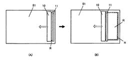
まず、図1に示すように、搬送装置30は、前工程から載置部31に載置されたワークS1を、接着剤供給部1に搬送する。接着剤供給部1においては、図1(A)、図3(A)に示すように、供給部10が、ワークS1の片面に対して、面状に接着剤Rを供給する。
First, as illustrated in FIG. 1, the
たとえば、図4に示すように、ディスペンサのノズルからワークS1に接着剤Rを供給(塗布、滴下)する。このディスペンサが、走査装置によって移動することにより、ワークS1の広範な領域に、接着剤Rが行き渡るように供給を開始する。 For example, as shown in FIG. 4, the adhesive R is supplied (applied or dropped) to the workpiece S1 from the nozzle of the dispenser. When the dispenser is moved by the scanning device, supply is started so that the adhesive R spreads over a wide area of the workpiece S1.
なお、接着剤Rは、貼り合わせのために必要な面状に塗布されればよい。たとえば、ワークの片面の全体に行き渡るように塗布してもよいし、一部に塗布されていない領域があってもよい。また、「全体に行き渡る」ように塗布する場合であっても、必ずしも、接着剤が面の縁に完全に達していなければならないわけではない。接着剤がわずかに縁に達していない部分があったとしても、全体に接着剤が行き渡っていると言ってもよい。 In addition, the adhesive agent R should just be apply | coated to the planar shape required for bonding. For example, you may apply | coat so that it may spread to the whole one side of a workpiece | work, and there may exist the area | region which is not apply | coated to one part. Further, even when the coating is applied so as to "spread the whole", the adhesive does not necessarily have to reach the edge of the surface completely. Even if there is a part where the adhesive does not reach the edge, it may be said that the adhesive is spread throughout.
たとえば、後述する図5のワークS2側のように、接着剤Rが面の縁にわずかに達していない場合でも、「全体に行き渡る」という概念に含まれる。つまり、たとえば、ワークS1に供給した接着剤Rの端が、図5のワークS2の縁と接着剤Rの端との関係のような状態となったとしても、「全体に行き渡る」と言ってもよい。 For example, even when the adhesive R does not reach the edge of the surface slightly like the workpiece S2 side in FIG. 5 described later, it is included in the concept of “spreading over the whole”. That is, for example, even if the end of the adhesive R supplied to the workpiece S1 is in a state like the relationship between the edge of the workpiece S2 and the end of the adhesive R in FIG. Also good.
供給部10とともに移動する仮硬化処理部11は、照射部からUV光を接着剤Rに照射して行く。たとえば、仮硬化処理部11は、供給部10とともに塗布方向に移動しながら、これに直交する方向に走査装置によって往復動する。これにより、図1(B)、図3(B)、図4に示すように、塗布済みの接着剤Rの全面に、UV光が照射されていく。
The temporary
UV光の照射は、大気中で行われるので、酸素阻害等により硬化の進行が遅くなり、適度な仮硬化状態の仮硬化部Hが得られる。このように、接着剤RをワークS1の端部まで供給しながら、供給済みの接着剤Rの全体を仮硬化部Hとする。 Since the irradiation with UV light is performed in the atmosphere, the progress of curing is delayed due to oxygen inhibition or the like, and a temporary cured portion H in an appropriate temporary cured state is obtained. In this manner, the supplied adhesive R as a whole is set as the temporary curing portion H while supplying the adhesive R to the end of the workpiece S1.
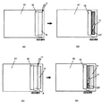
その後、搬送装置30は、接着剤Rが供給されたワークS1を、貼合部2に搬送する。貼合部2においては、図2(A)に示すように、押圧装置22にワークS2を保持した真空チャンバ21が下降して、ワークS1、S2の周囲が密閉される。そして、減圧ポンプが作動することにより、真空チャンバ21内の減圧(排気)が開始する。
Then, the conveying
真空引き完了後は、押圧装置22が下降することにより、ワークS1に対して、ワークS2が押し付けられる(図2(B))。このとき、接着剤Rの全体は、仮硬化部Hとなっているため、潰れによる流動が抑制される一方で、クッション性が維持されている。このため、貼り合わせ時の歪み等は吸収され、貼り合わせ厚の均一性を実現できる。また、仮硬化部Hは、表面の粘着性は維持されているので、ワークS2に対する接着力に問題はない。 After completion of evacuation, the work S2 is pressed against the work S1 by lowering the pressing device 22 (FIG. 2B). At this time, since the entirety of the adhesive R is a temporarily cured portion H, the flow due to crushing is suppressed, while the cushioning property is maintained. For this reason, the distortion | strain etc. at the time of bonding are absorbed, and the uniformity of bonding thickness is realizable. Moreover, since the tackiness of the surface of the pre-cured portion H is maintained, there is no problem with the adhesive force to the workpiece S2.
その後、排気路の開放等により真空破壊が行われ、真空チャンバ21が上昇することにより、貼り合わされたワークS1、S2は大気開放される。さらに、搬送装置30が、ワークS1、S2を貼合部2から次工程へと搬出する。たとえば、搬送装置30は、ワークS1、S2を、UV光の照射により接着剤Rを本硬化させる硬化部へと移動させる。
[C.効果]
以上のような本実施形態によれば、次のような効果が得られる。すなわち、ワークS1の片面に面状に広がるように接着剤Rを供給するとともに、仮硬化部Hを形成させるので、接着剤Rの流動が防止される。また、接着剤Rの供給とともに仮硬化部Hを形成するので、塗布完了後に硬化処理を行う場合に比べて、タクトタイムを短縮できる。さらに、仮硬化部Hは、クッション性は維持されるので、貼り合わせ時の歪み等が吸収され、均一な接着層を形成できる。
Thereafter, vacuum breakage is performed by opening the exhaust passage or the like, and the vacuum chamber 21 is raised, so that the bonded workpieces S1 and S2 are opened to the atmosphere. Furthermore, the
[C. effect]
According to the present embodiment as described above, the following effects can be obtained. That is, since the adhesive R is supplied so as to spread on one side of the workpiece S1 and the temporary curing portion H is formed, the flow of the adhesive R is prevented. Moreover, since the temporary hardening part H is formed with supply of the adhesive agent R, tact time can be shortened compared with the case where a hardening process is performed after completion of application. Furthermore, since the temporary curing portion H maintains the cushioning property, the distortion at the time of bonding is absorbed, and a uniform adhesive layer can be formed.
同じ接着剤Rを全面に供給した後、全面を仮硬化部Hとするので、たとえば、図5に示すように、ユーザの視野範囲W内に境界が残留することはなく、画面の視認性に影響がない。シール用の接着剤と内部充填用の接着剤とを別々に用意して供給する必要がないので、この点でもタクトタイムを短縮でき、コストも節約できる。 After the same adhesive R is supplied to the entire surface, the entire surface is set as the pre-cured portion H. For example, as shown in FIG. There is no effect. Since it is not necessary to prepare and supply the sealing adhesive and the internal filling adhesive separately, the tact time can be shortened and the cost can be saved.
さらに、たとえば、一般的に、真空貼り合わせを行う場合、未硬化の接着剤Rから発生するアウトガスによって、真空引きの速度が低下してしまう場合がある。しかし、本実施形態では、接着剤Rを仮硬化部Hとしているので、アウトガスの発生を抑制でき、真空引きの速度低下を防止できる。
[D.他の実施形態]
本発明は、上記のような実施形態に限定されるものではない。たとえば、仮硬化処理部11を、走査装置によって、供給部10とは独立に移動可能に設けることにより、接着剤Rの塗布と仮硬化とを交互に行うことも可能である。
Furthermore, for example, in general, when vacuum bonding is performed, the vacuuming speed may be reduced by the outgas generated from the uncured adhesive R. However, in this embodiment, since the adhesive R is the pre-cured portion H, the generation of outgas can be suppressed and a reduction in the vacuuming speed can be prevented.
[D. Other Embodiments]
The present invention is not limited to the embodiment as described above. For example, it is possible to alternately apply the adhesive R and temporarily cure the provisional
たとえば、図6(A)に示すように、供給部10が所定量移動して接着剤RをワークS1に塗布した後、一時停止する。そして、図6(B)に示すように、塗布済みの接着剤Rに対して、仮硬化処理部11の照射部がUV光を照射しながら移動することにより、接着剤Rを仮硬化部Hとする。
For example, as shown in FIG. 6A, the
次に、図6(C)に示すように、供給部10が所定量移動して接着剤RをワークS1に塗布した後、一時停止する。そして、図6(D)に示すように、塗布済みの接着剤Rに対して、仮硬化処理部11の照射部がUV光を照射しながら移動することにより、接着剤Rを仮硬化部Hとする。
Next, as shown in FIG. 6C, the
以上を繰り返すことにより、ワークS1への接着剤Rの供給とともに、仮硬化部Hを形成できる。これにより、接着剤Rの供給後、広がりがある程度落ち着いた状態で、仮硬化をさせることができる。 By repeating the above, the temporary curing portion H can be formed together with the supply of the adhesive R to the workpiece S1. Thereby, after supply of the adhesive R, temporary curing can be performed in a state where the spread has settled to some extent.
また、図7及び図8に示すように、仮硬化処理部11に、UV光を線状に照射するバー状の照射部を用いることが考えられる。図7(A)(B)は、図3と同様に、供給部10とともに移動しながら、仮硬化処理部11によって、UV光の照射を行うものである。これにより、駆動部分を少なくしつつ、接着剤Rの塗布と仮硬化を高速で行うことができる。
Moreover, as shown in FIG.7 and FIG.8, it is possible to use the bar-shaped irradiation part which irradiates UV light linearly for the temporary
図8(A)〜(D)は、バー状の照射装置である仮硬化処理部11を、走査装置によって、供給部10から独立して移動可能に設けた一例である。この態様によれば、図6(A)〜(D)と同様に、塗布と仮硬化を交互に行うことができる。この場合にも、仮硬化のためのUV光の照射を高速で行うことができる。
8A to 8D show an example in which a temporary
なお、図6及び図8に示すように、仮硬化処理部11を供給部10から独立して移動可能に設けた場合、若しくは仮硬化処理部11と供給部10との間隔を長くした場合、塗布と仮硬化に時間差を持たせることができる。たとえば、供給部10により連続して(一時停止なく)接着剤Rを供給するとともに、仮硬化処理部11により連続して(一時停止なく)仮硬化させるが、接着剤Rの供給開始と仮硬化処理部11による仮硬化の開始に時間差を設けることにより、接着剤Rが十分に面状に広がった後に仮硬化させることができる。
In addition, as shown in FIG.6 and FIG.8, when the temporary
また、図9〜図12に示すように、接着剤Rの一部に仮硬化部Hを形成して、接着剤Rの流動防止を図ることができる。たとえば、図9(A)(B)は、供給部10による接着剤の供給とともに、複数(単数でもよい)の仮硬化処理部11を、接着剤Rの塗布領域の縁に沿って移動させながら、UV光を照射する態様である。これにより、塗布領域の縁を枠状の仮硬化部として、流動を防止することができる。
Moreover, as shown in FIGS. 9-12, the temporary hardening part H can be formed in a part of adhesive R, and the flow prevention of the adhesive R can be aimed at. For example, in FIGS. 9A and 9B, while supplying the adhesive by the
さらに、バー状の仮硬化処理部11を用いる態様もある。たとえば、図10(A)に示すように、仮硬化処理部11によるUV光の照射範囲を、接着剤Rの塗布領域の開始端と終了端においては、塗布領域の全幅に亘るように設定する。開始端と終了端の間は、図10(B)に示すように、塗布領域の両端のみを照射するように設定する。
Furthermore, there is also an aspect in which a bar-shaped temporary
このような照射領域の変更は、バーの長手方向に配置された複数の光源の発光の有無若しくは照射部の発光の有無を制御することにより実現できる。また、照射範囲を選択的に変更できるシャッター、マスク等の遮蔽部を備えることによっても実現できる。これにより、接着剤Rの塗布領域の縁を枠状の仮硬化部Hとして、流動を防止することができる。 Such a change of the irradiation region can be realized by controlling the presence or absence of light emission of a plurality of light sources arranged in the longitudinal direction of the bar or the presence or absence of light emission of the irradiation unit. It can also be realized by providing a shielding part such as a shutter or a mask that can selectively change the irradiation range. Thereby, the edge of the application area | region of the adhesive agent R can be made into the frame-shaped temporary hardening part H, and a flow can be prevented.
なお、仮硬化部Hは、必ずしも枠状に形成する必要はない。図11(A)〜(D)に示すように、接着剤Rの塗布領域の少なくとも一部の縁に形成しても、流動防止効果は得られる。 In addition, the temporary hardening part H does not necessarily need to be formed in a frame shape. As shown in FIGS. 11A to 11D, even when formed on at least a part of the edge of the application region of the adhesive R, the flow preventing effect can be obtained.
このように、電磁波の照射により仮硬化部Hを形成する領域は、非常に狭い範囲とするとが可能である。これにより、仮硬化部Hと未硬化部との境界を、図4に示した視野範囲W外とすることができる。 Thus, the region where the pre-cured portion H is formed by irradiation with electromagnetic waves can be a very narrow range. Thereby, the boundary between the pre-cured portion H and the uncured portion can be outside the visual field range W shown in FIG.
さらに、図12(A)(B)に示すように、塗布領域に複数の線状、点状等に仮硬化部Hを形成してもよい。これは、図4のような仮硬化処理部11の照射部が移動する毎に照射するか、図7のようなバー状の照射部の発光若しくは遮蔽のタイミングを制御することによって、実現できる。この場合も、面状に同時に供給された同一の接着剤の一部を仮硬化させるに過ぎないため、視認可能な境界は、ほとんど残らない。
Furthermore, as shown in FIGS. 12A and 12B, the precured portion H may be formed in a plurality of lines, dots, or the like in the application region. This can be realized by irradiating each time the irradiation unit of the temporary
仮硬化の態様は、方形、円形、楕円形、その他の多角形、曲線円形等、特定の形状に仮硬化させたり、散点的に仮硬化させたりしてもよい。仮硬化させる領域は、必ずしも閉じた領域を構成していなくてもよい。上記のように、直線状であってもよいし、屈曲線状、曲線状であってもよい。 The pre-curing mode may be pre-cured to a specific shape such as a square, a circle, an ellipse, other polygons, a curved circle, or may be pre-cured in a scattered manner. The area to be temporarily cured does not necessarily constitute a closed area. As described above, it may be linear, bent, or curved.
なお、本発明において、「供給部による供給とともに、仮硬化させる」とは、少なくとも、接着剤の供給開始から終了までの間(供給中)に仮硬化処理が開始していればよい。接着剤は、ワークの片面に面状に供給できればよく、ワークの片面の全体であっても部分であってもよい。 In the present invention, “to be temporarily cured together with the supply by the supply unit” only needs to start the temporary curing process at least from the start to the end of supply of the adhesive (during supply). The adhesive only needs to be supplied in a planar shape on one side of the workpiece, and may be the whole or a portion of one side of the workpiece.
また、接着剤の供給部の構成、供給方法は、ワークの片面に面状に行き渡るように塗布できればよい。供給部を走査して線状に塗布する場合、上下、前後左右、回転等、どのように移動させるかは自由である。図13に示すように、供給部10が接着剤Rを、多数の線状に塗布するものであってもよい。この場合、独立したディスペンサを多数連ねたものでもよい。その他、ローラによって塗布する装置、スキージによって塗布する装置、スピン塗布する装置等、種々の装置が適用可能である。
Moreover, the structure of the supply part of an adhesive agent and the supply method should just be able to apply | coat so that it may spread across the surface of one side of a workpiece | work. When the supply unit is scanned and applied in a linear form, it is free to move in such a manner as to move up and down, front and rear, left and right, and rotate. As shown in FIG. 13, the
使用する接着剤の種類は、紫外線硬化型の樹脂には限定されない。電磁波や熱の照射により硬化する樹脂が一般的であるが、現在又は将来において利用可能なあらゆる接着剤に適用可能である。この場合、接着剤の種類に応じて、仮硬化処理部を、照射装置、加熱装置、乾燥装置等に変えることになる。 The type of adhesive used is not limited to ultraviolet curable resins. Resins that are cured by irradiation with electromagnetic waves or heat are generally used, but can be applied to any adhesive that can be used now or in the future. In this case, according to the kind of adhesive agent, a temporary hardening process part will be changed into an irradiation apparatus, a heating apparatus, a drying apparatus, etc.
また、貼合部、搬送部についても、現在又は将来において利用可能なあらゆる方法、装置が適用可能である。たとえば、貼合部について、ワークを保持する構造も、たとえば、メカチャック、静電チャック、真空チャック、粘着チャック等、どのような構造であってもよい。真空貼り合わせを行う空間も、下側の部材が昇降して密閉、開放を行う構造でも、ワークの通路のみが開閉する構造でもよい。さらに、必ずしも真空貼合装置でなくてもよく、大気中で貼り合わせを行う装置でもよい。 Moreover, all the methods and apparatuses which can be used now or in the future are applicable also about a bonding part and a conveyance part. For example, the structure for holding the workpiece with respect to the bonding portion may be any structure such as a mechanical chuck, an electrostatic chuck, a vacuum chuck, or an adhesive chuck. The space for vacuum bonding may be a structure in which the lower member is raised and lowered to be sealed and opened, or a structure in which only the work passage is opened and closed. Furthermore, the apparatus is not necessarily a vacuum bonding apparatus, and may be an apparatus that performs bonding in the atmosphere.
搬送装置も、たとえば、ターンテーブル、コンベア、送り機構等、どのような構造であってもよい。載置部は、たとえば、サセプタ等が考えられるが、ワークを支持できる支持体として機能するものであれば、どのような材質、形状であってもよい。水平方向に支持するものには限らない。ワークの搬送方法も、載置部に載置される場合には限定されない。移動する台上に直接載置されていてもよい。なお、ワークの移動について、作業者が手作業で行ってもよい。 The transport device may also have any structure such as a turntable, a conveyor, a feed mechanism, and the like. For example, a susceptor or the like can be considered as the mounting portion, but any material and shape may be used as long as they function as a support that can support the workpiece. It is not restricted to what supports in a horizontal direction. The method for transporting the workpiece is not limited to the case of being placed on the placement unit. It may be placed directly on a moving table. In addition, about the movement of a workpiece | work, an operator may perform manually.
また、貼り合せ対象となるワークは、カバーパネルと液晶モジュールのように、表示装置を構成するワークであって、片面に接着剤を面状に塗布して貼り合わせるものであれば、その大きさ、形状、材質等は問わない。ワークの一方に接着剤を供給する場合のみならず、双方に供給する場合にも適用可能である。この場合、双方のワークに接着剤を供給する場合、一方のワークの接着剤のみ仮硬化させても、双方のワークの接着剤を仮硬化させてもよい。 In addition, the work to be bonded is a work constituting a display device, such as a cover panel and a liquid crystal module, and if the adhesive is applied on one side in a planar shape and bonded, the size of the work Any shape, material, etc. are acceptable. The present invention is applicable not only when supplying an adhesive to one of the workpieces but also when supplying the adhesive to both. In this case, when supplying an adhesive to both workpieces, only the adhesive of one workpiece may be temporarily cured, or the adhesive of both workpieces may be temporarily cured.
1…接着剤供給部
2…貼合部
3…搬送部
10…供給部
11…仮硬化処理部
20…貼合装置
21…真空チャンバ
22…押圧装置
30…搬送装置
31…載置部
DESCRIPTION OF
Claims (8)
前記一対のワークの少なくとも一方のワークの片面に、面状に広がるように接着剤を供給する供給部と、
供給された接着剤を、流動せずかつ表面を未硬化部分が残留した状態に仮硬化させる仮硬化処理を、前記供給部による接着剤の供給開始から終了までの間に開始する仮硬化処理部と、
前記一対のワークを、前記仮硬化処理後の前記接着剤を介して貼り合わせる貼合部と、
前記貼合部により貼り合わされた前記一対のワーク間の接着剤を本硬化させる本硬化部と、
を有することを特徴とする貼合ワークの製造装置。 In the manufacturing apparatus of the bonded workpiece formed by bonding a pair of workpieces constituting the display device via an adhesive,
A supply unit for supplying an adhesive so as to spread in a planar shape on one surface of at least one of the pair of workpieces;
Temporary curing processing unit that starts a temporary curing process in which the supplied adhesive does not flow and the surface is temporarily cured in a state where an uncured part remains. When,
A bonding part that bonds the pair of workpieces through the adhesive after the temporary curing treatment;
A main curing part for main curing the adhesive between the pair of workpieces bonded by the bonding part;
The manufacturing apparatus of the bonding workpiece | work characterized by having.
前記仮硬化処理部は、接着剤に電磁波を照射する照射部を有することを特徴とする請求項1〜3のいずれか1項に記載の貼合ワークの製造装置。 The adhesive is an adhesive that is cured by irradiation with electromagnetic waves,
The said temporary hardening process part has an irradiation part which irradiates electromagnetic waves to an adhesive agent, The manufacturing apparatus of the bonding workpiece | work of any one of Claims 1-3 characterized by the above-mentioned.
前記照射部は、大気中で接着剤に紫外線を照射する紫外線照射装置を有することを特徴とする請求項4記載の貼合ワークの製造装置。 The adhesive is an ultraviolet curable resin,
The said irradiation part has an ultraviolet irradiation device which irradiates an ultraviolet-ray to an adhesive agent in air | atmosphere, The manufacturing apparatus of the bonding workpiece | work of Claim 4 characterized by the above-mentioned.
少なくとも一方のワークの片面に、面状に広がるように接着剤を供給し、
供給された接着剤を、流動せずかつ表面を未硬化部分が残留した状態に仮硬化させる仮硬化処理を、前記接着剤の供給開始から終了までの間に開始するようにして行ない、
前記仮硬化処理後、前記一対のワークを前記接着剤を介して貼り合わせ、
貼り合わせた前記一対のワーク間の接着剤を本硬化させる、
ことを特徴とする貼合ワークの製造方法。 In the method of bonding workpieces formed by bonding a pair of workpieces constituting the display device via the adhesive,
Supply adhesive on one side of at least one workpiece so that it spreads in a plane,
A temporary curing treatment is performed so that the supplied adhesive does not flow and the surface is temporarily cured in a state in which an uncured portion remains, so that the adhesive is started between the start and end of the supply of the adhesive,
After the temporary curing treatment, the pair of workpieces are bonded through the adhesive,
A main curing of the adhesive between the pair of workpieces bonded together;
The manufacturing method of the bonding workpiece | work characterized by this.
Priority Applications (1)
| Application Number | Priority Date | Filing Date | Title |
|---|---|---|---|
| JP2014112840A JP6026463B2 (en) | 2014-05-30 | 2014-05-30 | Bonding workpiece manufacturing apparatus and bonding workpiece manufacturing method |
Applications Claiming Priority (1)
| Application Number | Priority Date | Filing Date | Title |
|---|---|---|---|
| JP2014112840A JP6026463B2 (en) | 2014-05-30 | 2014-05-30 | Bonding workpiece manufacturing apparatus and bonding workpiece manufacturing method |
Related Parent Applications (1)
| Application Number | Title | Priority Date | Filing Date |
|---|---|---|---|
| JP2010219946A Division JP5558993B2 (en) | 2010-09-29 | 2010-09-29 | Adhesive supply device and adhesive supply method |
Related Child Applications (1)
| Application Number | Title | Priority Date | Filing Date |
|---|---|---|---|
| JP2016076174A Division JP6161759B2 (en) | 2016-04-05 | 2016-04-05 | Bonding workpiece manufacturing apparatus and bonding workpiece manufacturing method |
Publications (3)
| Publication Number | Publication Date |
|---|---|
| JP2014199457A JP2014199457A (en) | 2014-10-23 |
| JP2014199457A5 JP2014199457A5 (en) | 2015-01-08 |
| JP6026463B2 true JP6026463B2 (en) | 2016-11-16 |
Family
ID=52356352
Family Applications (1)
| Application Number | Title | Priority Date | Filing Date |
|---|---|---|---|
| JP2014112840A Active JP6026463B2 (en) | 2014-05-30 | 2014-05-30 | Bonding workpiece manufacturing apparatus and bonding workpiece manufacturing method |
Country Status (1)
| Country | Link |
|---|---|
| JP (1) | JP6026463B2 (en) |
Families Citing this family (1)
| Publication number | Priority date | Publication date | Assignee | Title |
|---|---|---|---|---|
| JP6722744B2 (en) * | 2018-11-15 | 2020-07-15 | モメンティブ・パフォーマンス・マテリアルズ・ジャパン合同会社 | Adhesive coating device |
Family Cites Families (8)
| Publication number | Priority date | Publication date | Assignee | Title |
|---|---|---|---|---|
| JP2908259B2 (en) * | 1994-12-09 | 1999-06-21 | ウシオ電機株式会社 | Method and apparatus for bonding liquid crystal panels |
| JP2003005194A (en) * | 2001-06-25 | 2003-01-08 | Shimadzu Corp | Sealing agent applying device, liquid crystal dropping and sticking device and manufacturing method for liquid crystal panel |
| JP2003093945A (en) * | 2001-09-27 | 2003-04-02 | Shimadzu Corp | Sealing compound applicator |
| JP2004170526A (en) * | 2002-11-18 | 2004-06-17 | Tokyo Electron Ltd | Method and device for manufacturing liquid crystal display element |
| US8088438B2 (en) * | 2004-06-03 | 2012-01-03 | Shibaura Mechatronics Corporation | Resin layer formation method, resin layer formation device, and disk manufacturing method |
| WO2008038414A1 (en) * | 2006-09-28 | 2008-04-03 | Shibaura Mechatronics Corporation | Bonding method and bonding apparatus |
| JP5139736B2 (en) * | 2007-06-27 | 2013-02-06 | 東レエンジニアリング株式会社 | Liquid crystal component manufacturing method and manufacturing apparatus |
| WO2009054168A1 (en) * | 2007-10-22 | 2009-04-30 | Sharp Kabushiki Kaisha | Display device and method for production thereof |
-
2014
- 2014-05-30 JP JP2014112840A patent/JP6026463B2/en active Active
Also Published As
| Publication number | Publication date |
|---|---|
| JP2014199457A (en) | 2014-10-23 |
Similar Documents
| Publication | Publication Date | Title |
|---|---|---|
| JP5558993B2 (en) | Adhesive supply device and adhesive supply method | |
| JP2012073533A (en) | Sticking device and sticking method | |
| JP5798750B2 (en) | Adhesive supply device and adhesive supply method | |
| JP6271289B2 (en) | Adhesive coating apparatus, display device member manufacturing apparatus, and display device member manufacturing method | |
| JP6315630B2 (en) | Display device member manufacturing apparatus and display device member manufacturing method | |
| JP5411905B2 (en) | Joining member manufacturing apparatus and joining member manufacturing method | |
| JP5657979B2 (en) | Bonding device and bonding method | |
| JP5727773B2 (en) | Adhesive supply device and adhesive supply method | |
| KR101852200B1 (en) | Bonding apparatus and bonding method | |
| JP6026463B2 (en) | Bonding workpiece manufacturing apparatus and bonding workpiece manufacturing method | |
| JP5815099B2 (en) | Bonding apparatus and manufacturing method of bonding substrate | |
| JP6161759B2 (en) | Bonding workpiece manufacturing apparatus and bonding workpiece manufacturing method | |
| JP5936747B2 (en) | Manufacturing apparatus and manufacturing method for members constituting display device | |
| JP2013015760A (en) | Adhesive supply device and adhesive supply method | |
| JP2017045010A (en) | Manufacturing device of member for display and manufacturing method of member for display | |
| TWI581866B (en) | Adhesive dissipation apparatus and method thereof, manufacturing apparatus for member of display device and method thereof | |
| JP5752402B2 (en) | Adhesive supply device and adhesive supply method | |
| TWI490049B (en) | Adhesive providing apparatus and adhesive providing method | |
| JP5885279B2 (en) | Bonding workpiece manufacturing apparatus and bonding workpiece manufacturing method | |
| KR101708956B1 (en) | Adhesive supply apparatus and adhesive supply method | |
| TWI541132B (en) | Bonding apparatus and manufacturing method for bonding substrates | |
| TWI542922B (en) | Laminating device and bonding method | |
| KR20130104591A (en) | Bonding apparatus and bonding method | |
| JP2015194727A (en) | Manufacturing machine of component for display device, and manufacturing method of component for display device | |
| KR101616198B1 (en) | Adhesive applicator, adhesive application method, apparatus and method for manufacturing a display device member |
Legal Events
| Date | Code | Title | Description |
|---|---|---|---|
| A521 | Request for written amendment filed |
Free format text: JAPANESE INTERMEDIATE CODE: A523 Effective date: 20141118 |
|
| A977 | Report on retrieval |
Free format text: JAPANESE INTERMEDIATE CODE: A971007 Effective date: 20150416 |
|
| A131 | Notification of reasons for refusal |
Free format text: JAPANESE INTERMEDIATE CODE: A131 Effective date: 20150602 |
|
| A521 | Request for written amendment filed |
Free format text: JAPANESE INTERMEDIATE CODE: A523 Effective date: 20150731 |
|
| A02 | Decision of refusal |
Free format text: JAPANESE INTERMEDIATE CODE: A02 Effective date: 20160105 |
|
| A521 | Request for written amendment filed |
Free format text: JAPANESE INTERMEDIATE CODE: A523 Effective date: 20160405 |
|
| A911 | Transfer to examiner for re-examination before appeal (zenchi) |
Free format text: JAPANESE INTERMEDIATE CODE: A911 Effective date: 20160412 |
|
| A912 | Re-examination (zenchi) completed and case transferred to appeal board |
Free format text: JAPANESE INTERMEDIATE CODE: A912 Effective date: 20160506 |
|
| A61 | First payment of annual fees (during grant procedure) |
Free format text: JAPANESE INTERMEDIATE CODE: A61 Effective date: 20161012 |
|
| R150 | Certificate of patent or registration of utility model |
Ref document number: 6026463 Country of ref document: JP Free format text: JAPANESE INTERMEDIATE CODE: R150 |
|
| S111 | Request for change of ownership or part of ownership |
Free format text: JAPANESE INTERMEDIATE CODE: R313113 |
|
| R350 | Written notification of registration of transfer |
Free format text: JAPANESE INTERMEDIATE CODE: R350 |
|
| R250 | Receipt of annual fees |
Free format text: JAPANESE INTERMEDIATE CODE: R250 |
|
| RD02 | Notification of acceptance of power of attorney |
Free format text: JAPANESE INTERMEDIATE CODE: R3D02 |
|
| R250 | Receipt of annual fees |
Free format text: JAPANESE INTERMEDIATE CODE: R250 |
|
| R250 | Receipt of annual fees |
Free format text: JAPANESE INTERMEDIATE CODE: R250 |