JP6023637B2 - Bench seat seat cushion structure - Google Patents

Bench seat seat cushion structure Download PDF

Info

Publication number
JP6023637B2
JP6023637B2 JP2013088861A JP2013088861A JP6023637B2 JP 6023637 B2 JP6023637 B2 JP 6023637B2 JP 2013088861 A JP2013088861 A JP 2013088861A JP 2013088861 A JP2013088861 A JP 2013088861A JP 6023637 B2 JP6023637 B2 JP 6023637B2
Authority
JP
Japan
Prior art keywords
seat
cushion
seat cushion
movable
tray
Prior art date
Legal status (The legal status is an assumption and is not a legal conclusion. Google has not performed a legal analysis and makes no representation as to the accuracy of the status listed.)
Active
Application number
JP2013088861A
Other languages
Japanese (ja)
Other versions
JP2014210543A (en
Inventor
康伸 河本
康伸 河本
洋介 長谷川
洋介 長谷川
Current Assignee (The listed assignees may be inaccurate. Google has not performed a legal analysis and makes no representation or warranty as to the accuracy of the list.)
Honda Motor Co Ltd
Tachi S Co Ltd
Original Assignee
Honda Motor Co Ltd
Tachi S Co Ltd
Priority date (The priority date is an assumption and is not a legal conclusion. Google has not performed a legal analysis and makes no representation as to the accuracy of the date listed.)
Filing date
Publication date
Application filed by Honda Motor Co Ltd, Tachi S Co Ltd filed Critical Honda Motor Co Ltd
Priority to JP2013088861A priority Critical patent/JP6023637B2/en
Publication of JP2014210543A publication Critical patent/JP2014210543A/en
Application granted granted Critical
Publication of JP6023637B2 publication Critical patent/JP6023637B2/en
Active legal-status Critical Current
Anticipated expiration legal-status Critical

Links

Images

Landscapes

  • Engineering & Computer Science (AREA)
  • Transportation (AREA)
  • Mechanical Engineering (AREA)
  • Aviation & Aerospace Engineering (AREA)
  • Passenger Equipment (AREA)
  • Seats For Vehicles (AREA)

Description

本発明は、ベンチシートのシートクッション構造に関するものである。   The present invention relates to a seat cushion structure for a bench seat.

従来、車両用シートとして、シートクッションが前側分割体及び後側分割体に分割され、そのうち前側分割体がシートクッションの前端部を中心に反転変形する構成が知られている(例えば、下記特許文献1参照)。前側分割体の裏面(初期状態における下面)には、物品を載置可能なテーブル部材が設けられている。
この構成によれば、初期状態において、前側分割体の表面は後側分割体の上面とともにシートクッションの座面を構成し、反転状態において、前側分割体の裏面が上向きに露出することで、テーブル部材上に物品を載置できるようになっている(いわゆる、反転テーブル構造)。
2. Description of the Related Art Conventionally, as a vehicle seat, a structure in which a seat cushion is divided into a front divided body and a rear divided body, and the front divided body is reversely deformed around the front end portion of the seat cushion (for example, the following patent document). 1). A table member on which an article can be placed is provided on the back surface (lower surface in the initial state) of the front divided body.
According to this configuration, in the initial state, the surface of the front divided body constitutes the seat surface of the seat cushion together with the upper surface of the rear divided body, and in the inverted state, the back surface of the front divided body is exposed upward, whereby the table An article can be placed on a member (so-called reverse table structure).

特開2005−297633号公報JP 2005-297633 A

ところで、近時ではリヤシート等、シートクッションが車幅方向の全体に亘って一体に形成された、いわゆるベンチシート型のシートクッションに上述した反転テーブル構造を採用することが検討されている。この場合、シートクッションのうち、中央着座部の前側部分に左右の着座部に対して後方に窪む切欠き部を形成し、この切欠き部内に前側分割体を反転可能に配置する構成が考えられる。   Recently, it has been studied to adopt the above-described reversing table structure for a so-called bench seat type seat cushion in which a seat cushion such as a rear seat is integrally formed over the entire vehicle width direction. In this case, in the seat cushion, a configuration is considered in which a notch portion that is recessed rearward with respect to the left and right seating portions is formed in the front portion of the central seating portion, and the front divided body is disposed in the notch portion so as to be able to be reversed. It is done.

しかしながら、上述したようにシートクッションの中央着座部に反転テーブル構造を採用する場合、後側部分は左右の着座部が中央着座部によって連設されるものの、前側部分は左右の着座部が切欠き部を介して離間することになり、シートクッション自体の剛性を確保することが難しい。   However, as described above, when the reversal table structure is adopted for the central seating portion of the seat cushion, the left and right seating portions are connected to the central seating portion in the rear portion, but the left and right seating portions are notched in the front portion. Therefore, it is difficult to ensure the rigidity of the seat cushion itself.

そこで、本発明は、上述した事情に考慮してなされたもので、剛性を確保した上で、利便性を向上させることができるベンチシートのシートクッション構造を提供することを目的とする。   Therefore, the present invention has been made in view of the above-described circumstances, and an object thereof is to provide a seat cushion structure of a bench seat that can improve convenience while ensuring rigidity.

上記目的を達成するために、請求項1に記載した発明は、左右の着座部(例えば、実施形態における左側着座部81及び右側着座部82)、及び該左右の着座部の間に配設された中央着座部(例えば、実施形態における中央着座部83)が幅方向に一体的に形成されたシートクッション(例えば、実施形態におけるシートクッション21)を備え、前記中央着座部は、前側に形成された切欠き部(例えば、実施形態における切欠き部86)内に設けられて前後方向に移動可能とされた可動クッション(例えば、実施形態における可動クッション85)を備えたベンチシートのシートクッション構造であって、前記可動クッションを車体フロア(例えば、実施形態における車体フロア11)に固定する固定座(例えば、実施形態における固定座54)と、前記シートクッションのうち、前記左右の着座部の下方に設けられ、前記左右の着座部をそれぞれ支持する左右のシートクッションフレーム(例えば、実施形態における左フレーム38及び右フレーム39)と、前記切欠き部内に配置されたトレイ(例えば、実施形態におけるトレイユニット71)と、前記左右のシートクッションフレームに連結されて前記トレイを支持するトレイ支持ワイヤ(例えば、実施形態におけるトレイ支持ワイヤ44)と、を備え、前記固定座は、左右の前記シートクッションフレームを左右方向で連結していることを特徴とする。 In order to achieve the above object, the invention described in claim 1 is provided between the left and right seats (for example, the left seat 81 and the right seat 82 in the embodiment) and the left and right seats. The central seat portion (for example, the central seat portion 83 in the embodiment) includes a seat cushion (for example, the seat cushion 21 in the embodiment) integrally formed in the width direction, and the central seat portion is formed on the front side. A bench seat seat cushion structure provided with a movable cushion (for example, the movable cushion 85 in the embodiment) provided in the cutout portion (for example, the notched portion 86 in the embodiment) and movable in the front-rear direction. A fixed seat (for example, the fixed seat in the embodiment) that fixes the movable cushion to the vehicle body floor (for example, the vehicle body floor 11 in the embodiment). 4) and left and right seat cushion frames (for example, the left frame 38 and the right frame 39 in the embodiment) that are provided below the left and right seating portions of the seat cushion and support the left and right seating portions, respectively. The tray (for example, the tray unit 71 in the embodiment) disposed in the notch , and the tray support wire that is connected to the left and right seat cushion frames and supports the tray (for example, the tray support wire 44 in the embodiment). ), And the fixed seat connects the left and right seat cushion frames in the left-right direction.

請求項2に記載した発明では、前記固定座には、前記可動クッションを前後方向に移動可能に支持する支持部(例えば、実施形態における支持フレーム58)が設けられていることを特徴とする。   The invention described in claim 2 is characterized in that the fixed seat is provided with a support portion (for example, a support frame 58 in the embodiment) that supports the movable cushion so as to be movable in the front-rear direction.

請求項3に記載した発明では、前記トレイは、前記可動クッションが前記切欠き部内に収容された着座状態において、前記可動クッションの下方に配置されるとともに、前記支持部に支持されていることを特徴とする。
請求項4に記載した発明では、前記トレイは、前記支持部を上方から覆うカバー体(例えば、実施形態におけるカバー体72)と、前記カバー体から延設されて物品を載置可能なトレイ体(例えば、実施形態におけるトレイ体73)と、が一体に形成されていることを特徴とする。
In the invention described in claim 3, wherein the tray is in the seating state in which the movable cushion is received in the notch portion, while being disposed below the movable cushion, that it is supported by the support portion Features.
In the invention described in claim 4, the tray includes a cover body (for example, the cover body 72 in the embodiment) that covers the support portion from above, and a tray body that extends from the cover body and on which an article can be placed. (For example, the tray body 73 in the embodiment) is integrally formed.

請求項1に記載した発明によれば、中央着座部に形成された可動クッション用の切欠き部によって、左右の着座部を支持する左右のシートクッションフレームが離間している場合であっても、これら左右のシートクッションフレーム間を固定座によって連結することで、シートクッションの剛性の低下を抑制した上で、上述した反転テーブル構造を採用することができ、利便性を向上させることができる。   According to the first aspect of the present invention, even if the left and right seat cushion frames supporting the left and right seating portions are separated by the movable cushion notch portion formed in the central seating portion, By connecting the left and right seat cushion frames with a fixed seat, the above-described reversing table structure can be employed while suppressing a decrease in rigidity of the seat cushion, and convenience can be improved.

請求項2に記載した発明によれば、可動クッションが支持部を介して固定座に支持されているため、固定座を左右のシートクッションフレーム及び車体フロアに固定した状態で、可動クッションを固定座とは別々に取り付けることができる。これにより、シートクッションの剛性を確保し、かつシートクッションのうち、可動クッション以外の部品を位置決めした状態で、可動クッションを取り付けることができる。よって、組み付け精度の向上を図るとともに、取り付け作業を効率的に行うことができる。   According to the second aspect of the present invention, since the movable cushion is supported by the fixed seat via the support portion, the movable cushion is fixed to the fixed seat while the fixed seat is fixed to the left and right seat cushion frames and the vehicle body floor. Can be attached separately. Accordingly, the movable cushion can be attached in a state in which the rigidity of the seat cushion is ensured and parts other than the movable cushion are positioned in the seat cushion. Therefore, it is possible to improve the assembling accuracy and efficiently perform the attaching operation.

請求項3に記載した発明によれば、着座状態に位置する可動クッションの下方に、トレイを配設することで、可動クッションの下方空間を有効活用することができ、利便性の更なる向上を図ることができる。
また、固定座を固定した状態で、上述したトレイを含め可動クッション側の部材を固定座と別々に取り付けることができる。これにより、組み付け精度の更なる向上を図るとともに、取り付け作業をより効率的に行うことができる。
According to the invention described in claim 3, by arranging the tray below the movable cushion located in the seated state, the lower space of the movable cushion can be used effectively, and the convenience is further improved. You can plan.
In addition, with the fixed seat fixed, the members on the movable cushion side including the tray described above can be attached separately from the fixed seat. As a result, the assembly accuracy can be further improved, and the mounting operation can be performed more efficiently.

車両の概略構成図(側面図)である。1 is a schematic configuration diagram (side view) of a vehicle. 可動クッションの着座状態、及びアームレストの格納状態を示す後列シートの斜視図である。It is a perspective view of the back row seat which shows the seating state of a movable cushion, and the storage state of an armrest. シートクッションフレームの平面図である。It is a top view of a seat cushion frame. シートクッションの要部を示す分解斜視図である。It is a disassembled perspective view which shows the principal part of a seat cushion. シートクッションの要部を後方から見た斜視図である。It is the perspective view which looked at the principal part of the seat cushion from back. 図2のA−A線に沿う断面図である。It is sectional drawing which follows the AA line of FIG. 可動クッションの載置状態、及びアームレストの使用状態を示す後列シートの斜視図である。It is a perspective view of the backseat sheet | seat which shows the mounting state of a movable cushion, and the use state of an armrest. 図7のB−B線に沿う断面図である。It is sectional drawing which follows the BB line of FIG.

次に、本発明の実施形態を図面に基づいて説明する。本実施形態では、車両の後列シートに本発明のベンチシートのシートクッション構造を採用した場合について説明する。なお、以下の説明における前後上下左右等の向きは、特に記載が無ければ車両における向きと同一とする。また、図中矢印UPは上方を、矢印FRは前方をそれぞれ示している。   Next, embodiments of the present invention will be described with reference to the drawings. This embodiment demonstrates the case where the seat cushion structure of the bench seat of this invention is employ | adopted for the back row seat of a vehicle. In the following description, the directions such as front, rear, up, down, left and right are the same as those in the vehicle unless otherwise specified. In the drawing, the arrow UP indicates the upper side, and the arrow FR indicates the front side.

[車両]
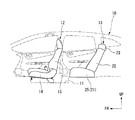
図1は、車両10の概略構成図(側面図)である。
図1に示すように、車両10の車体フロア11上には、前列シート12及び後列シート13が前後方向に間隔をあけて配列されている。
前列シート12は、シートクッション14と、シートクッション14の後端部に傾動可能に連結されたシートバック15と、を備え、前後方向にスライド移動可能に車体フロア11に固定されている。なお、図示しないが前列シート12は、車室内に左右一対で設けられている。
[vehicle]
FIG. 1 is a schematic configuration diagram (side view) of the vehicle 10.
As shown in FIG. 1, a front row seat 12 and a rear row seat 13 are arranged on the vehicle body floor 11 of the vehicle 10 at intervals in the front-rear direction.
The front row seat 12 includes a seat cushion 14 and a seat back 15 connected to a rear end portion of the seat cushion 14 so as to be tiltable, and is fixed to the vehicle body floor 11 so as to be slidable in the front-rear direction. Although not shown, the front row seats 12 are provided in a pair of left and right in the vehicle interior.

<後列シート>
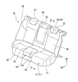
図2は可動クッション85の着座状態、及びアームレスト98の格納状態を示す後列シート13の斜視図である。
図2に示すように、本実施形態の後列シート13は、3名の乗員が着座可能な、いわゆるベンチシート型とされ、車室内における車幅方向の全体に亘って形成されている。具体的に、後列シート13は、車幅方向の全体に亘って延設されたシートクッション21と、シートクッション21の後端部に傾動可能に連結されたシートバック22と、シートバック22の上部において、車幅方向に間隔をあけて設けられた複数(図示の例では、3つ)のヘッドレスト23と、を備えている。
<Back row sheet>
FIG. 2 is a perspective view of the rear row seat 13 showing the seated state of the movable cushion 85 and the retracted state of the armrest 98.
As shown in FIG. 2, the rear row seat 13 of the present embodiment is a so-called bench seat type in which three passengers can be seated, and is formed over the entire vehicle width direction in the vehicle interior. Specifically, the rear row seat 13 includes a seat cushion 21 that extends over the entire vehicle width direction, a seat back 22 that is tiltably connected to a rear end portion of the seat cushion 21, and an upper portion of the seat back 22. Are provided with a plurality of (three in the illustrated example) headrests 23 provided at intervals in the vehicle width direction.

図3は、シートクッションフレーム24の平面図である。
図3に示すように、シートクッション21は、骨格をなすシートクッションフレーム24と、このシートクッションフレーム24を上方から被覆するクッションユニット25と、を備えている。
FIG. 3 is a plan view of the seat cushion frame 24.
As shown in FIG. 3, the seat cushion 21 includes a seat cushion frame 24 that forms a skeleton, and a cushion unit 25 that covers the seat cushion frame 24 from above.

<シートクッションフレーム>
シートクッションフレーム24は、金属等からなる複数のワイヤが折り曲げられた状態でそれぞれ溶接等により結合されてなり、全体として平面視C字状に外観構成されている。具体的に、シートクッションフレーム24は、車幅方向に間隔をあけて配置された平面視矩形状の左フレーム(シートクッションフレーム)38及び右フレーム(シートクッションフレーム)39を備えている。これら左フレーム38及び右フレーム39は、シートクッション21のうち、後述する左右の着座部81,82(図2参照)の外形形状に倣って延在する平面視矩形状とされ、左右の着座部81,82をそれぞれ下方から支持している。なお、左フレーム38及び右フレーム39は、左右対称の形状であるため、以下の説明では、左フレーム38について主に説明し、右フレーム39において左フレーム38と同様の構成については同一の符号を付して説明を省略する。
<Seat cushion frame>
The seat cushion frame 24 is joined by welding or the like in a state where a plurality of wires made of metal or the like are bent, and has an external appearance configured in a C shape in plan view as a whole. Specifically, the seat cushion frame 24 includes a left frame (seat cushion frame) 38 and a right frame (seat cushion frame) 39 that are rectangular in plan view and are arranged at intervals in the vehicle width direction. The left frame 38 and the right frame 39 have a rectangular shape in a plan view extending along the outer shape of left and right seating portions 81 and 82 (see FIG. 2), which will be described later, of the seat cushion 21, and the left and right seating portions. 81 and 82 are supported from below. Since the left frame 38 and the right frame 39 have symmetrical shapes, in the following description, the left frame 38 will be mainly described. In the right frame 39, the same reference numerals are used for the same configurations as the left frame 38. A description thereof will be omitted.

左フレーム38は、前方に向けて凸の平面視C字状に屈曲された前部ワイヤ31と、前部ワイヤ31を後方から取り囲む平面視L字状に屈曲された後部ワイヤ32と、を有している。   The left frame 38 has a front wire 31 bent in a C-shape that is convex toward the front, and a rear wire 32 bent in an L-shape that surrounds the front wire 31 from the rear. doing.

前部ワイヤ31において、車幅方向の外側に位置して、前後方向に沿って延在する外側延在部34は、後部ワイヤ32における車幅方向の外側端部に結合されている。左フレーム38において、外側延在部34の車幅方向の外側には、外側延在部34と後部ワイヤ32の外側端部を車幅方向の外側から取り囲む第1囲繞ワイヤ36が形成されている。
一方、前部ワイヤ31において、車幅方向の内側に位置して、前後方向に沿って延在する内側延在部35は、外側延在部34よりも長く形成され、後端部が後部ワイヤ32のうち車幅方向の内側端部に結合されている。左フレーム38において、前部ワイヤ31の前方には、前部ワイヤ31を前方から取り囲む第2囲繞ワイヤ37が形成されている。
In the front wire 31, an outer extending portion 34 that is located on the outer side in the vehicle width direction and extends along the front-rear direction is coupled to an outer end portion in the vehicle width direction of the rear wire 32. In the left frame 38, a first surrounding wire 36 that surrounds the outer extending portion 34 and the outer end of the rear wire 32 from the outer side in the vehicle width direction is formed outside the outer extending portion 34 in the vehicle width direction. .
On the other hand, in the front wire 31, the inner extending portion 35 that is located inside the vehicle width direction and extends along the front-rear direction is formed longer than the outer extending portion 34, and the rear end portion is the rear wire. 32 is coupled to the inner end in the vehicle width direction. In the left frame 38, a second surrounding wire 37 that surrounds the front wire 31 from the front is formed in front of the front wire 31.

そして、シートクッションフレーム24のうち、左フレーム38及び右フレーム39の間には、各後部ワイヤ32における車幅方向の内側端部同士を架け渡す第1左右ワイヤ41と、上述した内側延在部35の後部同士を架け渡す第2左右ワイヤ42と、が前後方向に間隔をあけて設けられている。第1左右ワイヤ41は、後方に向けて凸の平面視C字状とされ、第2左右ワイヤ42は車幅方向に沿って直線状に延在している。
そして、上述した各左右ワイヤ41,42、及び内側延在部35により画成された部分は、シートクッション21のうち、後述する固定クッション84(図2参照)を下方から支持する平面視矩形状の中央フレーム43を構成している。
In the seat cushion frame 24, between the left frame 38 and the right frame 39, the first left and right wires 41 that bridge the inner ends of the rear wires 32 in the vehicle width direction, and the above-described inner extending portions. The second left and right wires 42 that bridge the rear portions of the 35 are provided with a space in the front-rear direction. The first left and right wires 41 are formed in a C shape that is convex in the rearward direction, and the second left and right wires 42 extend linearly along the vehicle width direction.
A portion defined by the left and right wires 41 and 42 and the inner extending portion 35 described above has a rectangular shape in plan view that supports a fixed cushion 84 (see FIG. 2) to be described later from the seat cushion 21. The central frame 43 is configured.

図4はシートクッション21における要部の分解斜視図である。
図3、図4に示すように、シートクッションフレーム24のうち、各左右フレーム38,39間であって、中央フレーム43の前方に位置する部分には、後述するトレイユニット(トレイ)71を支持するトレイ支持ワイヤ44が設けられている。
トレイ支持ワイヤ44は、上述した各内側延在部35それぞれにおいて上方に向けて立設された側方支持ワイヤ51と、各内側延在部35間を架け渡す下方支持ワイヤ52と、下方支持ワイヤ52及び上述した第2左右ワイヤ42の間に位置して、各内側延在部35間を架け渡す後方支持ワイヤ53と、を有している。
FIG. 4 is an exploded perspective view of the main part of the seat cushion 21.
As shown in FIGS. 3 and 4, a later-described tray unit (tray) 71 is supported on a portion of the seat cushion frame 24 between the left and right frames 38 and 39 and in front of the central frame 43. A tray support wire 44 is provided.
The tray support wire 44 includes a side support wire 51 erected upward in each of the inner extension portions 35 described above, a lower support wire 52 that bridges between the inner extension portions 35, and a lower support wire. 52 and the second left and right wires 42 described above, and a rear support wire 53 that bridges between the inner extending portions 35.

下方支持ワイヤ52は、各内側延在部35間を車幅方向に沿って延在する直線状とされ、前後方向に間隔をあけて複数本配列されている。
また、後方支持ワイヤ53は、その延在方向(車幅方向)の中央部が上方に向けて膨出するように屈曲形成されている。
The lower support wires 52 have a linear shape extending between the inner extending portions 35 along the vehicle width direction, and a plurality of lower support wires 52 are arranged at intervals in the front-rear direction.
Further, the rear support wire 53 is bent so that the central portion in the extending direction (vehicle width direction) bulges upward.

<固定座>
ここで、左フレーム38及び右フレーム39の間であって、トレイ支持ワイヤ44の前方に位置する部分には、左フレーム38及び右フレーム39の前端部同士(具体的には、上述した第2囲繞ワイヤ37における車幅方向の内側端部同士)を架け渡す固定座54が設けられている。固定座54は、金属等からなり、車幅方向に沿って延在する板状とされている。固定座54における車幅方向の両端部には、車体フロア11に固定座54を締結固定するための取付孔55が形成されている。また、固定座54には、上述した取付孔55をそれぞれ前方から取り囲むようにストッパワイヤ56が連結されている。これらストッパワイヤ56は、その前端部が上方に向けて屈曲されている。
<Fixed seat>
Here, between the left frame 38 and the right frame 39 and in front of the tray support wire 44, the front end portions of the left frame 38 and the right frame 39 (specifically, the second frame described above). A fixed seat 54 is provided over the inner wire 37 in the vehicle width direction. The fixed seat 54 is made of metal or the like and has a plate shape extending along the vehicle width direction. Attachment holes 55 for fastening and fixing the fixed seat 54 to the vehicle body floor 11 are formed at both ends of the fixed seat 54 in the vehicle width direction. In addition, a stopper wire 56 is connected to the fixed seat 54 so as to surround the mounting holes 55 from the front. The front ends of these stopper wires 56 are bent upward.

また、固定座54のうち、車幅方向の中央部には、上方に向けて膨出する台座部57が形成され、この台座部57上に後述する可動クッション85を回動可能に支持する支持フレーム(支持部)58が固定されている。   Further, a pedestal portion 57 that bulges upward is formed in the center portion of the fixed seat 54 in the vehicle width direction, and a support that supports a movable cushion 85, which will be described later, on the pedestal portion 57 is rotatably supported. A frame (supporting portion) 58 is fixed.

<支持フレーム>
支持フレーム58は、車幅方向で対向する一対の支持板61と、各支持板61の下端部同士を連結する連結部62と、を有している。
まず、連結部62は、例えば車幅方向に沿って延在する円筒形状とされている。連結部62は、シートクッション21の前端部、具体的には上述した固定座54上に配設され、上述したストッパワイヤ56に後方から近接または当接している。連結部62には、前方に向けて突出するブラケット63が車幅方向に間隔をあけて複数設けられている。これらブラケット63には、上述した台座部57に上下方向で重なる位置まで延在しており、上述した台座部57にボルト等を介して締結固定されている。
<Support frame>
The support frame 58 includes a pair of support plates 61 that face each other in the vehicle width direction, and a connecting portion 62 that connects the lower ends of the support plates 61.
First, the connection part 62 is made into the cylindrical shape extended along the vehicle width direction, for example. The connecting portion 62 is disposed on the front end portion of the seat cushion 21, specifically on the above-described fixed seat 54, and approaches or contacts the above-described stopper wire 56 from the rear. The connecting portion 62 is provided with a plurality of brackets 63 protruding forward and spaced in the vehicle width direction. These brackets 63 extend to a position overlapping the above-described pedestal portion 57 in the vertical direction, and are fastened and fixed to the above-described pedestal portion 57 via bolts or the like.

支持板61は、車幅方向を厚さ方向とする板状とされ、上方に向かうに従い前後方向の幅が漸次拡大している。支持板61の上端部には、支持板61を厚さ方向に貫通する支持孔65が形成されるとともに、この支持孔65を下方から取り囲むようにガイド溝66が形成されている。ガイド溝66は、下方に向けて凸の半円形状とされている。なお、各支持板61には、支持孔65及びガイド溝66内、及び開口縁を覆うカラー67が車幅方向の内側から内装されている。   The support plate 61 has a plate shape in which the vehicle width direction is the thickness direction, and the width in the front-rear direction gradually increases toward the top. A support hole 65 penetrating the support plate 61 in the thickness direction is formed at the upper end portion of the support plate 61, and a guide groove 66 is formed so as to surround the support hole 65 from below. The guide groove 66 has a semicircular shape that protrudes downward. Each support plate 61 is internally provided with a collar 67 that covers the support hole 65 and the guide groove 66 and covers the opening edge from the inner side in the vehicle width direction.

<トレイユニット>
図5はシートクッション21の要部を示す斜視図である。
ここで、図4、図5に示すように、上述したトレイ支持ワイヤ44及び固定座54の上方には、トレイユニット71が配設されている。トレイユニット71は、上述した支持フレーム58を上方から覆うカバー体72と、カバー体72から後方に向けて延設されたトレイ体73と、が樹脂材料等により一体に形成されたものである。
<Tray unit>
FIG. 5 is a perspective view showing a main part of the seat cushion 21.
Here, as shown in FIGS. 4 and 5, a tray unit 71 is disposed above the tray support wire 44 and the fixed seat 54 described above. In the tray unit 71, a cover body 72 that covers the support frame 58 described above from above and a tray body 73 that extends backward from the cover body 72 are integrally formed of a resin material or the like.

カバー体72は、上述した連結部62上を車幅方向に沿って延在する連結部カバー74を備え、この連結部カバー74における車幅方向の外側端部には上述した支持板61を収容する一対の支持板カバー75が形成されている。なお、連結部カバー74は、後述する可動クッション85の前端部形状に倣って、側面視で下方に凸の湾曲形状とされている。   The cover body 72 includes a connecting portion cover 74 extending along the vehicle width direction on the connecting portion 62 described above, and the support plate 61 described above is accommodated at an outer end portion of the connecting portion cover 74 in the vehicle width direction. A pair of support plate covers 75 are formed. The connecting portion cover 74 has a curved shape convex downward in a side view, following the shape of the front end portion of the movable cushion 85 described later.

支持板カバー75は、下方に向けて開口するカップ状とされ、これら支持板カバー75の内側に上述した各支持板61がそれぞれ収容されている。また、支持板カバー75のうち、車幅方向において、支持板61の支持孔65及びガイド溝66と重なる部分(上述したカラー67と重なる部分)には、車幅方向に貫通する開口部76が形成され、この開口部76を通して支持孔65及びガイド溝66が車幅方向の両側に露出している。   The support plate cover 75 has a cup shape that opens downward, and each of the support plates 61 described above is accommodated inside the support plate cover 75. Further, in the support plate cover 75, an opening 76 that penetrates in the vehicle width direction is formed in a portion that overlaps the support hole 65 and the guide groove 66 of the support plate 61 in the vehicle width direction (portion that overlaps the collar 67 described above). The support hole 65 and the guide groove 66 are formed on both sides in the vehicle width direction through the opening 76.

トレイ体73は、上述した連結部カバー74の後端部から後方に向けて延設されており、上方に向けて開放された箱型とされている。トレイ体73は、上述したシートクッションフレーム24のトレイ支持ワイヤ44(側方支持ワイヤ51、下方支持ワイヤ52、及び後方支持ワイヤ53)によって車幅方向の両側、下方及び後方から支持されている。また、トレイ体73の外周面には、複数のリブ77が突設されている。
トレイ体73の上端縁には、外側に向けて張り出す外フランジ部78が形成されている。外フランジ部78の後端部のうち、車幅方向の両端に位置する部分には、ゴム等からなる緩衝材79が取り付けられている。これら緩衝材79は、後述する可動クッション85が当接可能とされている。
The tray body 73 extends rearward from the rear end portion of the connecting portion cover 74 described above, and has a box shape opened upward. The tray body 73 is supported from both sides in the vehicle width direction, from below and from the rear by the tray support wires 44 (side support wires 51, lower support wires 52, and rear support wires 53) of the seat cushion frame 24 described above. A plurality of ribs 77 project from the outer peripheral surface of the tray body 73.
An outer flange portion 78 that projects outward is formed at the upper end edge of the tray body 73. A cushioning material 79 made of rubber or the like is attached to portions located at both ends in the vehicle width direction of the rear end portion of the outer flange portion 78. These cushioning materials 79 can contact a movable cushion 85 described later.

<クッションユニット>
図2に示すように、クッションユニット25は、左右の着座部(左側着座部81及び右側着座部82)、及びこれら左右の着座部81,82間に位置する中央着座部83が車幅方向に一体となって外観構成され、これら各着座部81〜83上で各乗員の臀部を支持するようになっている。
<Cushion unit>
As shown in FIG. 2, the cushion unit 25 includes left and right seating portions (a left seating portion 81 and a right seating portion 82) and a central seating portion 83 positioned between the left and right seating portions 81 and 82 in the vehicle width direction. The outer appearance is integrally formed, and the occupant's buttocks are supported on each of the seating portions 81 to 83.

図6は図2のA−A線に沿う断面図である。
図2、図6に示すように、中央着座部83は、後側に位置する固定クッション84と、固定クッション84の前方に位置する可動クッション85と、に分割構成されている。具体的に、クッションユニット25のうち、中央着座部83の前側に位置する部分には、後方に向けて窪む切欠き部86が形成されており、この切欠き部86内に可動クッション85が収容されている。
すなわち、クッションユニット25は、左右の着座部81,82のうち、後側が中央着座部83の固定クッション84により一体的に連設され、前側は切欠き部86(図7参照)を挟んで離間している。図示の例において、切欠き部86は、上下方向、及び前方に向けて開放されるとともに、後端部が中央着座部83の前後方向に沿う中央部に位置している。また、切欠き部86は、車幅方向に沿う中央着座部83のほぼ全体に亘って形成されている。
6 is a cross-sectional view taken along line AA in FIG.
As shown in FIGS. 2 and 6, the central seating portion 83 is divided into a fixed cushion 84 positioned on the rear side and a movable cushion 85 positioned in front of the fixed cushion 84. Specifically, a portion of the cushion unit 25 located on the front side of the central seating portion 83 is formed with a notch 86 that is recessed toward the rear, and the movable cushion 85 is formed in the notch 86. Contained.
That is, the cushion unit 25 is integrally connected to the rear side of the left and right seating portions 81, 82 by the fixed cushion 84 of the central seating portion 83, and the front side is separated with a notch 86 (see FIG. 7) therebetween. doing. In the illustrated example, the notch portion 86 is opened in the vertical direction and forward, and the rear end portion is located at the central portion along the front-rear direction of the central seating portion 83. Further, the notch 86 is formed over substantially the entire central seat 83 along the vehicle width direction.

図4〜図6に示すように、可動クッション85は、直方体形状とされ、表面が固定クッション84の上面とともに中央着座部83の着座面を構成している。すなわち、可動クッション85の表面は、上述した固定クッション84、左右の着座部81,82の上面に滑らかに連なっている。また、可動クッション85の下方には、上述したトレイユニット71が配置されており、トレイユニット71が外部に露出しないようになっている。   As shown in FIGS. 4 to 6, the movable cushion 85 has a rectangular parallelepiped shape, and the surface constitutes the seating surface of the central seating portion 83 together with the upper surface of the fixed cushion 84. That is, the surface of the movable cushion 85 is smoothly connected to the upper surfaces of the fixed cushion 84 and the left and right seating portions 81 and 82 described above. In addition, the tray unit 71 described above is disposed below the movable cushion 85 so that the tray unit 71 is not exposed to the outside.

可動クッション85の前端部には、車幅方向の外側に向けて突出する一対の回動軸88が設けられている。回動軸88は、上述した支持フレーム58の支持孔65内で回動可能に支持されており、可動クッション85がシートクッション21の前部を起点にして回動することで、前方に移動し、かつ反転するようになっている。具体的に、可動クッション85は、表面が上方を向き、中央着座部83の着座面を構成する着座状態と、裏面が上方を向き、物品等を載置可能な載置状態(突出状態:図7,8参照)と、の間で変化するようになっている。
また、可動クッション85のうち、着座状態における回動軸88の前方には、回動軸88と平行に突出するガイドピン89が形成されている。ガイドピン89は、上述した支持フレーム58のガイド溝66内に収容されており、可動クッション85の回動動作に倣ってガイド溝66内を移動可能とされている。
A pair of pivot shafts 88 projecting outward in the vehicle width direction are provided at the front end of the movable cushion 85. The pivot shaft 88 is rotatably supported in the support hole 65 of the support frame 58 described above, and the movable cushion 85 moves forward by rotating with the front portion of the seat cushion 21 as a starting point. And it comes to reverse. Specifically, the movable cushion 85 has a seating state in which the front surface faces upward and constitutes the seating surface of the central seating portion 83, and a mounting state (protruding state: FIG. 7 and 8).
Further, a guide pin 89 that protrudes in parallel with the rotation shaft 88 is formed in front of the rotation shaft 88 in the seated state in the movable cushion 85. The guide pin 89 is accommodated in the guide groove 66 of the support frame 58 described above, and can move in the guide groove 66 following the rotating operation of the movable cushion 85.

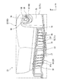
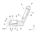
図7は、可動クッション85の載置状態、アームレスト98の使用状態を示す後列シート13の斜視図であり、図8は図7のB−B線に沿う断面図である。
図7、図8に示すように、可動クッション85は、上述した載置状態において、後端部が切欠き部86内に位置し、前端部が左右の着座部81,82よりも前方に向けて突出している。したがって、切欠き部86内において、固定クッション84と可動クッション85との間から、上述したトレイユニット71(トレイ体73)が開放されている。これにより、切欠き部86を通してトレイ体73に物品等を載置できるようになっている。また、可動クッション85の裏面、すなわち上述した載置状態で上方を向く面には、テーブル部材91が設けられている。
FIG. 7 is a perspective view of the rear row seat 13 showing the mounting state of the movable cushion 85 and the use state of the armrest 98, and FIG. 8 is a cross-sectional view taken along the line BB of FIG.
As shown in FIGS. 7 and 8, the movable cushion 85 has the rear end located in the notch 86 and the front end directed forward from the left and right seats 81, 82 in the above-described mounting state. Protruding. Therefore, the tray unit 71 (tray body 73) described above is opened from between the fixed cushion 84 and the movable cushion 85 in the notch 86. As a result, articles and the like can be placed on the tray body 73 through the notch 86. Further, a table member 91 is provided on the back surface of the movable cushion 85, that is, the surface facing upward in the above-described mounting state.

図4に示すように、テーブル部材91のうち、載置状態における後部には、頂壁部91aから下方に向けて窪む有底筒状のカップホルダ92が車幅方向に複数(図示の例では2つ)並設されている。これらカップホルダ92は、載置状態において、上下方向を軸方向とする円筒状とされ、その内側にドリンク容器等を収容できるようになっている。なお、各カップホルダ92は、車幅方向の内側端部同士が連通部93を介して連通している。   As shown in FIG. 4, a plurality of bottomed cylindrical cup holders 92 recessed downward from the top wall portion 91 a are arranged in the vehicle width direction at the rear portion of the table member 91 in the mounted state (example shown in the figure). Then there are two). These cup holders 92 have a cylindrical shape whose axial direction is the vertical direction in the mounted state, and can accommodate a drink container or the like inside thereof. Each cup holder 92 communicates with the inner end portions in the vehicle width direction via a communication portion 93.

また、テーブル部材91のうち、載置状態における前部には、物品等を載置可能なテーブル部94が形成されている。テーブル部94は、頂壁部91aから下方に向けて窪んだ箱型とされ、その底面部94a上に物品等を載置できるようになっている。なお、図5に示すように、テーブル部材91の頂壁部91aは、上述した着座状態において、トレイ体73の緩衝材79に当接した状態でトレイユニット71を上方から覆っている。   Further, a table portion 94 on which an article or the like can be placed is formed in the front portion of the table member 91 in the placement state. The table portion 94 has a box shape that is recessed downward from the top wall portion 91a, and an article or the like can be placed on the bottom surface portion 94a. As shown in FIG. 5, the top wall portion 91 a of the table member 91 covers the tray unit 71 from above in a state where the top wall portion 91 a is in contact with the cushioning material 79 of the tray body 73 in the above-described seating state.

<シートバック>
図2に示すように、シートバック22は、左右の背もたれ部(左側背もたれ部95及び右側背もたれ部96)、及びこれら左右の背もたれ部95,96間に位置する中央背もたれ部97が車幅方向に一体となって外観構成されたものであり、各背もたれ部95〜97に対応して上述したヘッドレスト23がそれぞれ設けられている。なお、後列シート13のうち、車幅方向で対応する着座部81〜83、背もたれ部95〜97、及びヘッドレスト23により左側シート、中央シート、及び右側シートが構成されている。
<Seatback>
As shown in FIG. 2, the seat back 22 has left and right backrest portions (left backrest portion 95 and right backrest portion 96), and a central backrest portion 97 located between the left and right backrest portions 95, 96 in the vehicle width direction. The headrest 23 mentioned above is provided corresponding to each backrest part 95-97. In the rear row seat 13, the left seat, the center seat, and the right seat are configured by the seating portions 81 to 83, the backrest portions 95 to 97, and the headrest 23 corresponding in the vehicle width direction.

シートバック22のうち、中央背もたれ部97には、後方に向けて窪み、内部にアームレスト98を格納可能なアームレスト格納部99(図7参照)が形成されている。アームレスト格納部99は、正面視において上下方向に長い長方形状とされ、車幅方向に沿う中央背もたれ部97のほぼ全体に亘って形成されている。そして、アームレスト格納部99のうち、車幅方向を向く縦側壁部の下端部には、図示しない回動軸を介してアームレスト98の下端部が回動可能に支持されている。なお、図示の例において、アームレスト98は車幅方向に沿う幅が上述した可動クッション85と同等になっている。   In the seat back 22, the central backrest 97 is formed with an armrest storage 99 (see FIG. 7) that is recessed rearward and that can store the armrest 98 therein. The armrest storage portion 99 has a rectangular shape that is long in the vertical direction when viewed from the front, and is formed over substantially the entire center backrest portion 97 along the vehicle width direction. And the lower end part of the armrest 98 is rotatably supported by the lower end part of the vertical side wall part which faces the vehicle width direction among the armrest storage parts 99 via the rotating shaft which is not shown in figure. In the illustrated example, the armrest 98 has a width along the vehicle width direction equivalent to the movable cushion 85 described above.

アームレスト98は、直方体形状とされ、上述した回動軸周りに回動することで、アームレスト格納部99内に格納された格納状態(図2,6参照)と、シートバック22に対して前方に突出した使用状態(図7,8参照)と、の間で変位するようになっている。アームレスト98の表面は、上述した格納状態において、中央背もたれ部97の前面と段差なく滑らかに連なっており、中央背もたれ部97の前面とともに中央シートに着座する乗員の背中を支持するようになっている。   The armrest 98 has a rectangular parallelepiped shape, and rotates around the rotation axis described above, so that the armrest 98 is stored in the armrest storage unit 99 (see FIGS. 2 and 6) and forward with respect to the seat back 22. It is displaced between the protruding usage state (see FIGS. 7 and 8). In the retracted state described above, the surface of the armrest 98 is smoothly connected to the front surface of the central backrest portion 97 without a step, and supports the back of an occupant sitting on the central seat together with the front surface of the central backrest portion 97. .

一方、図7、図8に示すように、アームレスト98は、上述した使用状態において、裏面が上方を向いた状態でシートクッション21に沿って前方に向けて延在しており、左右シートに着座した乗員の腕を載置できるようになっている。   On the other hand, as shown in FIGS. 7 and 8, the armrest 98 extends forward along the seat cushion 21 with the back surface facing upward in the use state described above, and is seated on the left and right seats. The occupant ’s arms can be placed.

また、使用状態において、アームレスト98の前端部は、上述した着座状態における固定クッション84の前端縁(切欠き部86の後端縁)よりも前方に位置しており、着座状態の可動クッション85の後端部と上下方向で重なるように配置されている。さらに、使用状態のアームレスト98は、少なくとも前端部が上述した可動クッション85の回動軌跡L内に位置している。なお、図示の例では、可動クッション85の回動軌跡における中間部分(可動クッション85が上方に向けて立設された状態)において、可動クッション85の上端と、使用状態におけるアームレスト98の裏面と、がほぼ同じ高さに位置するようになっている。   In use, the front end of the armrest 98 is positioned in front of the front end edge of the fixed cushion 84 in the seated state (the rear end edge of the notch 86), and the movable cushion 85 in the seated state It arrange | positions so that it may overlap with a rear-end part in an up-down direction. Further, the armrest 98 in use is at least in the front end portion located in the rotation locus L of the movable cushion 85 described above. In the example shown in the figure, in the intermediate portion (the state in which the movable cushion 85 is erected upward) in the rotation locus of the movable cushion 85, the upper end of the movable cushion 85, the back surface of the armrest 98 in the used state, Are positioned at almost the same height.

<後列シートの使用方法>
次に、上述した後列シート13の使用方法について説明する。
上述の後列シート13では、可動クッション85を着座状態、アームレスト98を格納状態とすることで、3人の乗員が左右のシート及び中央シートにそれぞれ車幅方向に並んで着座できるようになっている。
<How to use the back row sheet>
Next, the usage method of the back row sheet | seat 13 mentioned above is demonstrated.
In the rear row seat 13 described above, the movable cushion 85 is in the seating state and the armrest 98 is in the retracted state, so that three passengers can be seated side by side in the vehicle width direction on the left and right seats and the center seat, respectively. .

一方、可動クッション85を載置状態とするには、まず可動クッション85の後端部を引き上げ、可動クッション85を支持フレーム58の支持孔65周りに回動させることで、可動クッション85が前方に移動するとともに、反転する。これにより、可動クッション85のテーブル部材91が上方を向き、かつ切欠き部86を通してトレイ体73が開放された載置状態となる。   On the other hand, in order to place the movable cushion 85 in the mounted state, first, the rear end portion of the movable cushion 85 is pulled up, and the movable cushion 85 is moved forward by rotating the movable cushion 85 around the support hole 65 of the support frame 58. Move and flip. As a result, the table member 91 of the movable cushion 85 faces upward and the tray body 73 is opened through the notch 86.

また、アームレスト98を使用状態とするには、格納状態におけるアームレスト98の上端部を引き下げ、アームレスト98を回動軸周りに回動させる。これにより、アームレスト98は、裏面が上方を向いた状態でシートクッション21に沿って前方に向けて延在する使用状態となる。
このように、可動クッション85を載置状態、アームレスト98を使用状態とした場合には、中央シートには着座できないものの、2人の乗員が左右のシートにそれぞれ着座できるようになっている。そして、左右のシートに着座した乗員は、アームレスト98に腕を載置したり、トレイ体73やテーブル部材91上に載置された物品やドリンク容器等を使用したりすることができる。
In order to put the armrest 98 in the use state, the upper end portion of the armrest 98 in the retracted state is pulled down, and the armrest 98 is rotated around the rotation axis. Thereby, armrest 98 will be in the use state extended toward the front along seat cushion 21 in the state where the back turned up.
In this way, when the movable cushion 85 is placed and the armrest 98 is in use, two passengers can seat on the left and right seats, although they cannot be seated on the center seat. The occupants seated on the left and right seats can place their arms on the armrest 98 or use articles, drink containers, or the like placed on the tray body 73 or the table member 91.

また、上述したように本実施形態では、使用状態のアームレスト98は、少なくとも前端部が上述した可動クッション85の回動軌跡L内に位置しているため、使用状態のアームレスト98と、載置状態の可動クッション85と、を近接して配置することができる。そのため、乗員がアームレスト98に腕を載置した状態で、テーブル部材91に載置されたドリンク容器や物品等に簡単に届くようになっている。   Further, as described above, in the present embodiment, the armrest 98 in use is at least the front end portion located in the rotation locus L of the movable cushion 85 described above. The movable cushion 85 can be disposed close to each other. Therefore, the occupant can easily reach a drink container or an article placed on the table member 91 with his / her arm placed on the armrest 98.

以上のように、本実施形態では、可動クッション85を支持する固定座54により、シートクッションフレーム24のうち、左右のフレーム38,39間を架け渡す構成とした。
この構成によれば、中央着座部83に形成された可動クッション85用の切欠き部86によって、左右の着座部81,82を支持する左右のフレーム38,39が離間している場合であっても、これら左右のフレーム38,39間のうちシートクッション21の切欠き部86に位置する部分を固定座54によって連結することで、シートクッション21の剛性の低下を抑制した上で、反転テーブル構造を採用することができ、利便性を向上させることができる。
As described above, in the present embodiment, the left and right frames 38 and 39 of the seat cushion frame 24 are bridged by the fixed seat 54 that supports the movable cushion 85.
According to this configuration, the left and right frames 38 and 39 supporting the left and right seating portions 81 and 82 are separated by the notch 86 for the movable cushion 85 formed in the central seating portion 83. In addition, by connecting a portion of the left and right frames 38 and 39 located at the notch portion 86 of the seat cushion 21 by the fixed seat 54, a reduction in rigidity of the seat cushion 21 is suppressed, and a reversing table structure is provided. Can be employed, and convenience can be improved.

また、可動クッション85が支持フレーム58を介して固定座54に支持されているため、固定座54を左右のフレーム38,39及び車体フロア11に固定した状態で、可動クッション85を固定座54とは別々に取り付けることができる。
これにより、シートクッション21の剛性を確保し、かつシートクッション21のうち、可動クッション85以外の部分を位置決めした状態で、可動クッション85を取り付けることができる。よって、組み付け精度の向上を図るとともに、取り付け作業を効率的に行うことができる。
Further, since the movable cushion 85 is supported by the fixed seat 54 via the support frame 58, the movable cushion 85 is fixed to the fixed seat 54 with the fixed seat 54 fixed to the left and right frames 38 and 39 and the vehicle body floor 11. Can be attached separately.
Thereby, the movable cushion 85 can be attached in a state where the rigidity of the seat cushion 21 is ensured and a portion of the seat cushion 21 other than the movable cushion 85 is positioned. Therefore, it is possible to improve the assembling accuracy and efficiently perform the attaching operation.

さらに、着座状態に位置する可動クッション85の下方に、トレイユニット71を配設することで、可動クッション85の下方空間を有効活用することができ、利便性の更なる向上を図ることができる。
また、固定座54を固定した状態で、上述したトレイユニット71を含め可動クッション85側の部材を固定座54と別々に取り付けることができる。これにより、組み付け精度の更なる向上を図るとともに、取り付け作業をより効率的に行うことができる。
Furthermore, by disposing the tray unit 71 below the movable cushion 85 located in the seated state, the space below the movable cushion 85 can be used effectively, and the convenience can be further improved.
Further, with the fixed seat 54 fixed, members on the movable cushion 85 side including the tray unit 71 described above can be attached separately from the fixed seat 54. As a result, the assembly accuracy can be further improved, and the mounting operation can be performed more efficiently.

なお、本発明の技術範囲は、上述した各実施形態に限定されるものではなく、本発明の趣旨を逸脱しない範囲において、上述した実施形態に種々の変更を加えたものを含む。すなわち、上述した実施形態で挙げた構成等はほんの一例に過ぎず、適宜変更が可能である。
例えば、上述した実施形態では、可動クッション85を回動(反転)させる構成について説明した、これに限らず、可動クッション85が前後方向に移動可能とされていれば、例えばスライドさせる構成等にしても構わない。
また、上述した実施形態では、本発明のシートクッション構造を後列シート13に採用する構成について説明したが、これに限られない。
The technical scope of the present invention is not limited to the above-described embodiments, and includes those in which various modifications are made to the above-described embodiments without departing from the spirit of the present invention. In other words, the configuration described in the above-described embodiment is merely an example, and can be changed as appropriate.
For example, in the above-described embodiment, the configuration for rotating (reversing) the movable cushion 85 has been described. However, the present invention is not limited to this. It doesn't matter.
Moreover, although embodiment mentioned above demonstrated the structure which employ | adopts the seat cushion structure of this invention for the back row seat 13, it is not restricted to this.

上述した実施形態では、アームレスト98を有するベンチシートについて説明したが、アームレスト98を有さない構成にしても構わない。
さらに、上述した実施形態においては、可動クッション85の裏面に、テーブル部材91を設ける構成について説明したが、これに限らず、種々の構成を採用することが可能である。
また、上述した実施形態では、支持フレーム58を介して可動クッション85を固定座54に固定する構成について説明したが、これに限らず、固定座54に可動クッション85を直接固定しても構わない。
In the embodiment described above, the bench seat having the armrest 98 has been described, but a configuration without the armrest 98 may be employed.
Furthermore, in the above-described embodiment, the configuration in which the table member 91 is provided on the back surface of the movable cushion 85 has been described. However, the present invention is not limited to this, and various configurations can be employed.
In the above-described embodiment, the configuration in which the movable cushion 85 is fixed to the fixed seat 54 via the support frame 58 has been described. However, the present invention is not limited thereto, and the movable cushion 85 may be directly fixed to the fixed seat 54. .

その他、本発明の趣旨を逸脱しない範囲で、上述した実施形態における構成要素を周知の構成要素に置き換えることは適宜可能であり、また、上述した変形例を適宜組み合わせてもよい。   In addition, in the range which does not deviate from the meaning of this invention, it is possible to replace suitably the component in the embodiment mentioned above by the known component, and you may combine the modification mentioned above suitably.

11…車体フロア 21…シートクッション 38…左フレーム(シートクッションフレーム) 39…右フレーム(シートクッションフレーム) 54…固定座 58…支持フレーム(支持部) 71…トレイユニット(トレイ) 81…左側着座部 82…右側着座部 83…中央着座部 85…可動クッション 86…切欠き部 DESCRIPTION OF SYMBOLS 11 ... Vehicle body floor 21 ... Seat cushion 38 ... Left frame (seat cushion frame) 39 ... Right frame (seat cushion frame) 54 ... Fixed seat 58 ... Support frame (support part) 71 ... Tray unit (tray) 81 ... Left seat part 82 ... Right side seating part 83 ... Center seating part 85 ... Movable cushion 86 ... Notch part

Claims (4)

左右の着座部、及び該左右の着座部の間に配設された中央着座部が幅方向に一体的に形成されたシートクッションを備え、
前記中央着座部は、前側に形成された切欠き部内に設けられて前後方向に移動可能とされた可動クッションを備えたベンチシートのシートクッション構造であって、
前記可動クッションを車体フロアに固定する固定座と、
前記シートクッションのうち、前記左右の着座部の下方に設けられ、前記左右の着座部をそれぞれ支持する左右のシートクッションフレームと、
前記切欠き部内に配置されたトレイと、
前記左右のシートクッションフレームに連結されて前記トレイを支持するトレイ支持ワイヤと、を備え、
前記固定座は、左右の前記シートクッションフレームを左右方向で連結していることを特徴とするベンチシートのシートクッション構造。
A seat cushion in which a left and right seating portion and a central seating portion disposed between the left and right seating portions are integrally formed in the width direction;
The central seating portion is a seat cushion structure of a bench seat provided with a movable cushion provided in a notch portion formed on the front side and movable in the front-rear direction,
A fixed seat for fixing the movable cushion to a vehicle body floor;
The left and right seat cushion frames that are provided below the left and right seating portions of the seat cushion and respectively support the left and right seating portions,
A tray disposed in the notch,
A tray support wire connected to the left and right seat cushion frames to support the tray , and
The seat cushion structure for a bench seat, wherein the fixed seat connects the left and right seat cushion frames in the left-right direction.
前記固定座には、前記可動クッションを前後方向に移動可能に支持する支持部が設けられていることを特徴とする請求項1記載のベンチシートのシートクッション構造。   The seat cushion structure for a bench seat according to claim 1, wherein the fixed seat is provided with a support portion that supports the movable cushion so as to be movable in the front-rear direction. 前記トレイは、前記可動クッションが前記切欠き部内に収容された着座状態において、前記可動クッションの下方に配置されるとともに、前記支持部に支持されていることを特徴とする請求項2記載のベンチシートのシートクッション構造。 The tray is in the seating state in which the movable cushion is received in the notch portion, while being disposed below the movable cushion, bench according to claim 2, characterized in that it is supported by the support portion Seat cushion structure of the seat. 前記トレイは、前記支持部を上方から覆うカバー体と、前記カバー体から延設されて物品を載置可能なトレイ体と、が一体に形成されていることを特徴とする請求項3記載のベンチシートのシートクッション構造。  4. The tray according to claim 3, wherein a cover body that covers the support portion from above and a tray body that extends from the cover body and on which an article can be placed are integrally formed. Bench seat seat cushion structure.
JP2013088861A 2013-04-19 2013-04-19 Bench seat seat cushion structure Active JP6023637B2 (en)

Priority Applications (1)

Application Number Priority Date Filing Date Title
JP2013088861A JP6023637B2 (en) 2013-04-19 2013-04-19 Bench seat seat cushion structure

Applications Claiming Priority (1)

Application Number Priority Date Filing Date Title
JP2013088861A JP6023637B2 (en) 2013-04-19 2013-04-19 Bench seat seat cushion structure

Publications (2)

Publication Number Publication Date
JP2014210543A JP2014210543A (en) 2014-11-13
JP6023637B2 true JP6023637B2 (en) 2016-11-09

Family

ID=51930642

Family Applications (1)

Application Number Title Priority Date Filing Date
JP2013088861A Active JP6023637B2 (en) 2013-04-19 2013-04-19 Bench seat seat cushion structure

Country Status (1)

Country Link
JP (1) JP6023637B2 (en)

Family Cites Families (1)

* Cited by examiner, † Cited by third party
Publication number Priority date Publication date Assignee Title
JP5221898B2 (en) * 2007-05-28 2013-06-26 富士重工業株式会社 Vehicle seat

Also Published As

Publication number Publication date
JP2014210543A (en) 2014-11-13

Similar Documents

Publication Publication Date Title
US7819468B2 (en) Seat for vehicle
JP6362948B2 (en) Seat back frame
JP7518414B2 (en) Vehicle seats
WO2014104213A1 (en) Seat device
JP5298580B2 (en) Vehicle seat
JP4569823B2 (en) Vehicle seat
JP2024071551A (en) Vehicle seat
JP6524198B2 (en) Vehicle seat
JP6023637B2 (en) Bench seat seat cushion structure
JP5381092B2 (en) Vehicle seat device
JP2021079894A (en) Arm rest of vehicle seat
JP4517295B2 (en) Vehicle seat
JP2011131662A (en) Vehicle luggage compartment space structure
JP2019073095A (en) Vehicle seat and component member
JP6646237B2 (en) Vehicle seat
JP6708941B2 (en) Vehicle seat
JP6691308B2 (en) Vehicle seat
JP2013184488A (en) Headrest
JP7157317B2 (en) vehicle seat
JP2011213154A (en) Seat device of vehicle
JP2018095053A (en) Vehicle seat
JP2022147826A (en) vehicle seat
JP2012188085A (en) Vehicle seat
JP6419536B2 (en) Vehicle seat
JP5458832B2 (en) Vehicle seat device

Legal Events

Date Code Title Description
A621 Written request for application examination

Free format text: JAPANESE INTERMEDIATE CODE: A621

Effective date: 20151006

A977 Report on retrieval

Free format text: JAPANESE INTERMEDIATE CODE: A971007

Effective date: 20160706

A131 Notification of reasons for refusal

Free format text: JAPANESE INTERMEDIATE CODE: A131

Effective date: 20160712

A521 Request for written amendment filed

Free format text: JAPANESE INTERMEDIATE CODE: A523

Effective date: 20160901

TRDD Decision of grant or rejection written
A01 Written decision to grant a patent or to grant a registration (utility model)

Free format text: JAPANESE INTERMEDIATE CODE: A01

Effective date: 20160927

A61 First payment of annual fees (during grant procedure)

Free format text: JAPANESE INTERMEDIATE CODE: A61

Effective date: 20161007

R150 Certificate of patent or registration of utility model

Ref document number: 6023637

Country of ref document: JP

Free format text: JAPANESE INTERMEDIATE CODE: R150

R250 Receipt of annual fees

Free format text: JAPANESE INTERMEDIATE CODE: R250

R250 Receipt of annual fees

Free format text: JAPANESE INTERMEDIATE CODE: R250

R250 Receipt of annual fees

Free format text: JAPANESE INTERMEDIATE CODE: R250

R250 Receipt of annual fees

Free format text: JAPANESE INTERMEDIATE CODE: R250

R250 Receipt of annual fees

Free format text: JAPANESE INTERMEDIATE CODE: R250