JP6020380B2 - Fuel injection valve - Google Patents
Fuel injection valve Download PDFInfo
- Publication number
- JP6020380B2 JP6020380B2 JP2013161594A JP2013161594A JP6020380B2 JP 6020380 B2 JP6020380 B2 JP 6020380B2 JP 2013161594 A JP2013161594 A JP 2013161594A JP 2013161594 A JP2013161594 A JP 2013161594A JP 6020380 B2 JP6020380 B2 JP 6020380B2
- Authority
- JP
- Japan
- Prior art keywords
- hole
- nozzle hole
- nozzle
- fuel
- holes
- Prior art date
- Legal status (The legal status is an assumption and is not a legal conclusion. Google has not performed a legal analysis and makes no representation as to the accuracy of the status listed.)
- Active
Links
Images


Classifications
-
- F—MECHANICAL ENGINEERING; LIGHTING; HEATING; WEAPONS; BLASTING
- F02—COMBUSTION ENGINES; HOT-GAS OR COMBUSTION-PRODUCT ENGINE PLANTS
- F02M—SUPPLYING COMBUSTION ENGINES IN GENERAL WITH COMBUSTIBLE MIXTURES OR CONSTITUENTS THEREOF
- F02M61/00—Fuel-injectors not provided for in groups F02M39/00 - F02M57/00 or F02M67/00
- F02M61/16—Details not provided for in, or of interest apart from, the apparatus of groups F02M61/02 - F02M61/14
- F02M61/18—Injection nozzles, e.g. having valve seats; Details of valve member seated ends, not otherwise provided for
- F02M61/1806—Injection nozzles, e.g. having valve seats; Details of valve member seated ends, not otherwise provided for characterised by the arrangement of discharge orifices, e.g. orientation or size
- F02M61/1846—Dimensional characteristics of discharge orifices
-
- F—MECHANICAL ENGINEERING; LIGHTING; HEATING; WEAPONS; BLASTING
- F02—COMBUSTION ENGINES; HOT-GAS OR COMBUSTION-PRODUCT ENGINE PLANTS
- F02M—SUPPLYING COMBUSTION ENGINES IN GENERAL WITH COMBUSTIBLE MIXTURES OR CONSTITUENTS THEREOF
- F02M61/00—Fuel-injectors not provided for in groups F02M39/00 - F02M57/00 or F02M67/00
- F02M61/16—Details not provided for in, or of interest apart from, the apparatus of groups F02M61/02 - F02M61/14
- F02M61/18—Injection nozzles, e.g. having valve seats; Details of valve member seated ends, not otherwise provided for
- F02M61/1806—Injection nozzles, e.g. having valve seats; Details of valve member seated ends, not otherwise provided for characterised by the arrangement of discharge orifices, e.g. orientation or size
- F02M61/1826—Discharge orifices having different sizes
-
- F—MECHANICAL ENGINEERING; LIGHTING; HEATING; WEAPONS; BLASTING
- F02—COMBUSTION ENGINES; HOT-GAS OR COMBUSTION-PRODUCT ENGINE PLANTS
- F02M—SUPPLYING COMBUSTION ENGINES IN GENERAL WITH COMBUSTIBLE MIXTURES OR CONSTITUENTS THEREOF
- F02M61/00—Fuel-injectors not provided for in groups F02M39/00 - F02M57/00 or F02M67/00
- F02M61/16—Details not provided for in, or of interest apart from, the apparatus of groups F02M61/02 - F02M61/14
- F02M61/18—Injection nozzles, e.g. having valve seats; Details of valve member seated ends, not otherwise provided for
- F02M61/1806—Injection nozzles, e.g. having valve seats; Details of valve member seated ends, not otherwise provided for characterised by the arrangement of discharge orifices, e.g. orientation or size
- F02M61/1833—Discharge orifices having changing cross sections, e.g. being divergent
Description
本発明は、内燃機関に設けられた燃焼室内へ向けて燃料を噴射する燃料噴射弁に関する。 The present invention relates to a fuel injection valve that injects fuel into a combustion chamber provided in an internal combustion engine.
従来、例えば特許文献1,2に開示のような燃料噴射弁には、燃焼室内へ向けて燃料を噴射する複数の噴孔が形成されている。特に特許文献2の燃料噴射弁では、複数形成された噴孔のうちで、一つの噴孔の内径が、他の噴孔の内径と異なっている。このように複数の噴孔の内径を互いに異ならせる構成によれば、燃料噴射弁から噴射される噴霧の形状は、内燃機関の燃料室の形状に適合し易くなる。 Conventionally, for example, in a fuel injection valve as disclosed in Patent Documents 1 and 2, a plurality of injection holes for injecting fuel into a combustion chamber are formed. In particular, in the fuel injection valve of Patent Document 2, the inner diameter of one nozzle hole is different from the inner diameters of the other nozzle holes among the plurality of nozzle holes formed. Thus, according to the structure which makes the internal diameter of a some injection hole mutually differ, the shape of the spray injected from a fuel injection valve becomes easy to adapt to the shape of the fuel chamber of an internal combustion engine.
しかし、特許文献2に開示の燃料噴射弁のように、一つの噴孔の内径が他の噴孔の内径と異なる場合、各噴孔から噴射される噴霧の特性も、互いに異なり得る。そのため、各噴孔から噴射される燃料の粒径が互いに異なる、或いは各噴孔から噴射される噴霧の広がりの態様(以下、「噴霧変化率」)が互いに異なる等の事態が生じ得た。 However, when the inner diameter of one injection hole is different from the inner diameter of another injection hole as in the fuel injection valve disclosed in Patent Document 2, the characteristics of the spray injected from each injection hole may be different from each other. For this reason, a situation may occur in which the particle diameters of the fuels injected from the respective nozzle holes are different from each other, or the modes of spread of the sprays injected from the respective nozzle holes (hereinafter referred to as “spray change rates”) are different from each other.
本発明は、このような問題に鑑みてなされたものであって、その目的は、燃料噴射弁に形成される複数の噴孔の内径が互いに異なっていても、各噴孔から噴射される噴霧の特性を近似させることが可能な燃料噴射弁を提供することにある。 The present invention has been made in view of such problems, and an object thereof is to spray sprayed from each nozzle hole even if the inner diameters of the plurality of nozzle holes formed in the fuel injection valve are different from each other. It is an object of the present invention to provide a fuel injection valve capable of approximating these characteristics.
上記目的を達成するために、第一の発明は、有底円筒状のノズルボディに形成された複数の噴孔(155)から内燃機関に設けられた燃焼室内へ向けて燃料を噴射する燃料噴射弁であって、複数の噴孔は、ノズルボディの中心軸線(18)周りの同一仮想円(19)上に入口側開口(156)を位置させており、且つ、基準となる基準内径(Dn1,Dn2,Dn201,Dn202)が互いに異なる第一噴孔(155a,255a)及び第二噴孔(155b,255b)を含み、第一噴孔及び第二噴孔は、各基準内径を維持しつつ延伸する筒孔形状であり、第一噴孔の流路長さ(Ln1,Ln201)を第一噴孔の基準内径(Dn1,Dn201)によって除算した値は、第二噴孔の流路長さ(Ln2,Ln202)を第二噴孔の基準内径(Dn2,Dn202)によって除算した値に揃えられ、第一噴孔の流路長さを第一噴孔の基準内径によって除算した値、及び第二噴孔の流路長さを第二噴孔の基準内径によって除算した値は共に、1.45以上、1.85以下であることを特徴としている。 To achieve the above object, the first invention is a fuel for injecting fuel toward a plurality of injection holes formed in the bottomed cylindrical nozzle body (155) into the combustion chamber provided in the internal combustion engine In the injection valve, the plurality of injection holes have an inlet side opening (156) positioned on the same virtual circle (19) around the central axis (18) of the nozzle body, and a reference inner diameter (reference) Dn1, Dn2, Dn201, Dn202) include different first injection holes (155a, 255a) and second injection holes (155b, 255b), and the first injection holes and the second injection holes maintain respective reference inner diameters. The value obtained by dividing the flow path length (Ln1, Ln201) of the first nozzle hole by the reference inner diameter (Dn1, Dn201) of the first nozzle hole is a cylindrical hole shape that extends while being (Ln2, Ln202) is the reference inner diameter of the second nozzle hole Dn2 and Dn202), the value obtained by dividing the flow length of the first injection hole by the reference inner diameter of the first injection hole, and the flow length of the second injection hole of the second injection hole. Both values divided by the reference inner diameter are 1.45 or more and 1.85 or less.
本願発明者は、燃料噴射弁における噴霧の微粒化特性が噴孔の流路長さ及び基準内径の比と関連していることを見出した。そこで第一の発明では、流路長さを基準内径によって除算した値が第一噴孔及び第二噴孔において互いに揃えられている。故に、これらの噴孔における基準内径が互いに異なっていても、第一噴孔及び第二噴孔の微粒化特性は、互いに近似し得る。以上によれば、燃料噴射弁は、内燃機関の燃料室に適合した噴霧形状を形成しつつ、各噴孔から噴射される噴霧についても粒径のばらつきを低減させることができる。
さらに本願発明者は、基準内径の維持された噴孔から噴射される噴霧の長さ(以下、「噴霧長さ」)について、流路長さを基準内径によって除算した値と相関があることを見出した。そこでこの発明のように、基準内径に対する流路長さの上限を規定することにより、噴孔内を流れる燃料が整流されすぎてしまう事態は、回避され得る。こうした思想に基づいて流路長さを基準内径によって除算した値の上限を設けることによれば、第一噴孔及び第二噴孔の基準内径が互いに異なっていても、これらの噴孔から噴射される燃料の噴霧長さは、共に抑制され得る。したがって、燃料噴射弁は、内燃機関の燃料室にさらに最適な形状の噴霧を形成できるようになる。
The inventor of the present application has found that the atomization characteristics of the spray in the fuel injection valve are related to the ratio of the flow path length of the injection hole and the reference inner diameter. Therefore, in the first invention, values obtained by dividing the flow path length by the reference inner diameter are aligned with each other in the first nozzle hole and the second nozzle hole. Therefore, even if the reference inner diameters of these nozzle holes are different from each other, the atomization characteristics of the first nozzle hole and the second nozzle hole can be approximated to each other. According to the above, the fuel injection valve can reduce the variation in the particle diameter of the spray injected from each injection hole while forming the spray shape suitable for the fuel chamber of the internal combustion engine .
Furthermore, the inventor of the present application has a correlation with the value obtained by dividing the flow path length by the reference inner diameter with respect to the length of the spray injected from the nozzle hole in which the reference inner diameter is maintained (hereinafter referred to as “spray length”). I found it. Therefore, as in the present invention, by defining the upper limit of the flow path length with respect to the reference inner diameter, a situation in which the fuel flowing through the nozzle hole is excessively rectified can be avoided. By providing the upper limit of the value obtained by dividing the flow path length by the reference inner diameter based on such an idea, even if the reference inner diameters of the first injection hole and the second injection hole are different from each other, the injection is performed from these injection holes. Both the spray lengths of the fuel to be performed can be suppressed. Therefore, the fuel injection valve can form a spray having a more optimal shape in the fuel chamber of the internal combustion engine.
また本願発明者は、噴孔から噴射される噴霧の変化率と、噴孔の流路長さを基準内径によって除算した値との間に関連を見出した。そこで第二の発明は、有底円筒状のノズルボディに形成された複数の噴孔から内燃機関に設けられた燃焼室内へ向けて燃料を噴射する燃料噴射弁であって、複数の噴孔は、ノズルボディの中心軸線(18)周りの同一仮想円(19)上に入口側開口(356)を位置させており、且つ、基準となる基準内径(Dn301,Dn302)が互いにに異なる第一噴孔(355a)及び第二噴孔(355b)を含み、第一噴孔及び第二噴孔は、燃料上流側から燃料下流側に向かうに従って各基準内径から拡径するテーパ孔形状であり、第一噴孔の流路長さ(Ln301)を第一噴孔の基準内径(Dn301)によって除算した値、及び第二噴孔の流路長さ(Ln302)を第二噴孔の基準内径(Dn302)によって除算した値は共に、2.0以上であることを特徴としている。 The inventor of the present application also found a relationship between the rate of change of the spray injected from the nozzle hole and the value obtained by dividing the flow path length of the nozzle hole by the reference inner diameter. Therefore the second invention is a fuel injection valve for injecting fuel toward a plurality of injection holes formed in the bottomed cylindrical nozzle body into the combustion chamber provided in the internal combustion engine, a plurality of injection holes Has an inlet side opening (356) located on the same virtual circle (19) around the central axis (18) of the nozzle body, and the reference inner diameters (Dn301, Dn302) which are different from each other are different from each other. Including a nozzle hole (355a) and a second nozzle hole (355b), and the first nozzle hole and the second nozzle hole have a tapered hole shape that expands from each reference inner diameter toward the fuel downstream side from the fuel upstream side, The value obtained by dividing the channel length (Ln301) of the first nozzle hole by the reference inner diameter (Dn301) of the first nozzle hole, and the channel length (Ln302) of the second nozzle hole are set to the reference inner diameter ( Both values divided by Dn302) are 2.0 or more. It is characterized in that.
これらの発明のように、基準内径に対する流路長さが確保されていれば、噴孔内を流れる燃料に整流作用が生じ得る。そのため、噴孔から噴射された噴霧は、噴孔の向けられた方向に安定して飛ぶことができる。こうした思想に基づき、流路長さを基準内径によって除算した値を上述の所定値以上確保することによれば、第一噴孔及び第二噴孔の基準内径が互いに異なっていても、これらの噴孔から噴射される噴霧の変化率は、互いに近似し且つ安定的な値となる。したがって、燃料噴射弁は、内燃機関の燃料室に適合した形状の噴霧を安定的に形成できるようになる。 If the flow path length with respect to the reference inner diameter is ensured as in these inventions, a rectifying action can occur in the fuel flowing in the nozzle hole. Therefore, the spray injected from the nozzle hole can fly stably in the direction in which the nozzle hole is directed. Based on this idea, by securing a value obtained by dividing the flow path length by the reference inner diameter above the predetermined value, even if the reference inner diameters of the first injection hole and the second injection hole are different from each other, The rate of change of the spray sprayed from the nozzle holes is a value that approximates and is stable. Therefore, the fuel injection valve can stably form a spray having a shape suitable for the fuel chamber of the internal combustion engine.
尚、上記括弧内の参照番号は、本発明の理解を容易にすべく、後述する実施形態における具体的な構成との対応関係の一例を示すものにすぎず、本発明の範囲を何ら制限するものではない。 Note that the reference numbers in the parentheses are merely examples of correspondences with specific configurations in the embodiments to be described later in order to facilitate understanding of the present invention, and limit the scope of the present invention. It is not a thing.
以下、本発明の複数の実施形態を図面に基づいて説明する。尚、各実施形態において対応する構成要素には同一の符号を付すことにより、重複する説明を省略する場合がある。各実施形態において構成の一部分のみを説明している場合、当該構成の他の部分については、先行して説明した他の実施形態の構成を適用することができる。また、各実施形態の説明において明示している構成の組み合わせばかりではなく、特に組み合わせに支障が生じなければ、明示していなくても複数の実施形態の構成同士を部分的に組み合わせることができる。そして、複数の実施形態及び変形例に記述された構成同士の明示されていない組み合わせも、以下の説明によって開示されているものとする。 Hereinafter, a plurality of embodiments of the present invention will be described with reference to the drawings. In addition, the overlapping description may be abbreviate | omitted by attaching | subjecting the same code | symbol to the corresponding component in each embodiment. When only a part of the configuration is described in each embodiment, the configuration of the other embodiment described above can be applied to the other part of the configuration. Moreover, not only the combination of the configurations explicitly described in the description of each embodiment, but also the configuration of a plurality of embodiments can be partially combined even if they are not explicitly described, as long as there is no problem in the combination. And the combination where the structure described in several embodiment and the modification is not specified shall also be disclosed by the following description.
(第一実施形態)
図1に示す本発明の第一実施形態による燃料噴射弁10は、内燃機関としてのガソリンエンジンに設置され、当該ガソリンエンジンに設けられた燃焼室(図示しない)内へ向けて燃料を噴射する。尚、かかる適用形態以外にも、例えば燃料噴射弁10は、ガソリンエンジンの燃焼室に連通する吸気通路へ燃料を噴射するものであってもよいし、内燃機関としてのディーゼルエンジンの燃焼室へ燃料を噴射するものであってもよい。
(First embodiment)
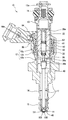
A
燃料噴射弁10は、弁ボディ11、固定コア20、可動コア30、弁部材40、弾性部材50、並びに駆動部60を備えている。
The
弁ボディ11は、コアハウジング12、入口部材13、ノズルホルダ14及びノズルボディ15等から構成されている。コアハウジング12は円筒状に形成されており、軸方向の一端部側から他端部側へ向かって順に第一磁性部12a、非磁性部12b及び第二磁性部12cを有している。磁性材からなる各磁性部12a,12cと、非磁性材からなる非磁性部12bとは、レーザ溶接等によって結合されている。かかる結合構造によって非磁性部12bは、第一磁性部12aと第二磁性部12cの間において磁束が短絡するのを防止している。
The
第二磁性部12cにおいて非磁性部12bとは反対側の軸方向端部には、円筒状の入口部材13が固定されている。入口部材13は、燃料ポンプ(図示しない)から燃料が供給される燃料入口13aを形成している。燃料入口13aへの供給燃料を濾過して下流側のコアハウジング12内へ導くために第一実施形態では、入口部材13の内周側に燃料フィルタ16が固定されている。
A
第一磁性部12aにおいて非磁性部12bとは反対側の軸方向端部には、磁性材によって円筒状に形成されたノズルホルダ14を介して、ノズルボディ15が固定されている。ノズルボディ15は有底円筒状に形成されており、コアハウジング12及びノズルホルダ14と共同して燃料通路17を内周側に形成している。図2に示すようにノズルボディ15は、弁座部150及びサック部152を有している。
A
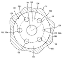
弁座部150は、軸方向のうち燃料下流側へ向かうに従って一定の縮径率で縮径するテーパ面状の内周面によって、弁座面151を形成している。サック部152は、弁座面151によって燃料通路17を形成する弁座部150の燃料下流側に、隣接している。サック部152は、燃料上流側の燃料通路17へ向かって開口する凹部153を、カップ状に形成している。この凹部153においてサック室154を形成する内面には、当該サック室154と連通する噴孔155が開口している。図2,3に示すように第一実施形態の噴孔155は、ノズルボディ15の中心軸線18周りに互いに間隔をあけて複数設けられている。各噴孔155の各入口側開口156は、中心軸線18周りの同一仮想円19上に位置している。また各噴孔155は、燃料下流側となる各出口側開口157へ向かうに従って凹部153の外周側に傾斜している。
The
図1に示すように固定コア20は、磁性材によって円筒状に形成されており、コアハウジング12のうち非磁性部12b及び第二磁性部12cの内周面に同軸上に固定されている。固定コア20には、その径方向中央部を軸方向に貫通する貫通孔20aが設けられている。燃料入口13aから燃料フィルタ16を経て貫通孔20aへ流入する燃料は、その下流側となる可動コア30側へ向かって当該貫通孔20aから流出することとなる。
As shown in FIG. 1, the fixed
可動コア30は、磁性材によって段付円筒状に形成されており、コアハウジング12の内周側に同軸上に配置されて燃料上流側の固定コア20と軸方向に対向している。可動コア30は、コアハウジング12のうち非磁性部12bの内周壁によって案内されることで、軸方向両側への正確な往復移動が可能となっている。可動コア30には、その径方向中央部を軸方向に貫通する第一貫通孔30aと、軸方向中間部を径方向に貫通して第一貫通孔30aに連通する第二貫通孔30bとが、設けられている。固定コア20の貫通孔20aから流出した燃料は、その下流側において可動コア30の第一貫通孔30aへ流入し、第二貫通孔30bからコアハウジング12内の燃料通路17へと流出することになる。
The
弁部材40は、非磁性材によって横断面が円形のニードル状に形成されており、弁ボディ11のうち要素12,14,15が内周側に形成する燃料通路17内に同軸上に配置されている。弁部材40において燃料上流側の軸方向端部は、可動コア30の第一貫通孔30aの内周面に同軸上に固定されている。また図1,2に示すように、弁部材40において燃料下流側の軸方向端部は、軸方向のうち燃料下流側へ向かうに従って縮径する当接部41を形成しており、弁座面151に対して当該当接部41を当接可能に対向させている。弁部材40は、所定の中心軸線18に沿った変位によって弁座面151に対し当接部41を離着座させる。こうして、噴孔155からの燃料噴射が断続される。具体的には、弁部材40が当接部41を弁座面151から離座させる開弁作動時には、燃料が燃料通路17からサック室154へ流入して各噴孔155から燃焼室へ噴射される。また一方、弁部材40が当接部41を弁座面151に着座させる閉弁作動時には、各噴孔155から燃焼室への燃料噴射が遮断されるのである。
The
図1に示すように、弾性部材50は金属製の圧縮コイルスプリングからなり、固定コア20に設けられた貫通孔20aの内周側に同軸上に収容されている。弾性部材50の一端部は、貫通孔20aの内周面に固定されたアジャスティングパイプ22の軸方向端部に係止されている。弾性部材50の他端部は、可動コア30のうち第一貫通孔30aの内面に係止されている。かかる係止構造によって弾性部材50は、それを挟む要素22,30間にて圧縮されることによって弾性変形する。したがって、弾性部材50が弾性変形によって発生する復原力は、弁部材40と共に可動コア30を燃料下流側へ付勢する付勢力となる。
As shown in FIG. 1, the
駆動部60は、コイル61、樹脂ボビン62、磁性ヨーク63、コネクタ64等から構成されている。コイル61は、樹脂ボビン62に金属線材を巻回してなり、その外周側に磁性ヨーク63が配置されている。コイル61は、コアハウジング12のうち固定コア20の外周側となる非磁性部12b及び第二磁性部12cの外周面に、樹脂ボビン62を介して同軸上に固定されている。コイル61は、コネクタ64に設けられたターミナル64aを介して外部の制御回路(図示しない)と電気接続されており、当該制御回路によって通電制御されるようになっている。
The
ここで、コイル61が通電によって励磁するときには、磁性ヨーク63、ノズルホルダ14、第一磁性部12a、可動コア30、固定コア20及び第二磁性部12cが共同して形成する磁気回路に、磁束が流れる。その結果、可動コア30と固定コア20との間に、可動コア30を燃料上流側の固定コア20へ向かって吸引する磁気吸引力が発生する。また一方、通電の停止によってコイル61が消磁するときには、上述の磁気回路に磁束が流れなくなるため、可動コア30と固定コア20との間において磁気吸引力が消失するのである。
Here, when the
このように構成された燃料噴射弁10の開弁作動では、コイル61への通電が開始されることで、磁気吸引力が可動コア30に作用する。すると、弁部材40と共に可動コア30は、弾性部材50の復原力に抗して固定コア20側へと移動することで、当該固定コア20と当接して停止する。その結果、弁座面151から当接部41が離座した状態となるので、各噴孔155から燃料が噴射されることとなる。
In the valve opening operation of the
こうした開弁作動後における燃料噴射弁10の閉弁作動では、コイル61への通電が停止されることで、可動コア30に作用する磁気吸引力が消失する。すると、弁部材40と共に可動コア30は、弾性部材50の復原力による付勢側へと移動することで、当該弁部材40を弁座面151と当接させて停止する。その結果、弁座面151に当接部41が着座した状態となるので、各噴孔155からの燃料噴射が停止することとなる。
In the valve closing operation of the
次に、図2,3に示す凹部153近傍の構成を詳細に説明する。凹部153の底壁160は、弁座面151に当接部41を着座させた弁部材40に対して、距離をあけて対向するよう形成されている。こうした対向構造によって、当接部41が弁座面151に着座したときの弁部材40の先端面42と底壁160との間には、各噴孔155と連通するサック室154が形成される。サック室154は、燃料中の混入異物(コンタミネーション)の噛み込みを抑制できるように容積を規定されている。
Next, the configuration near the
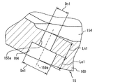
底壁160の底面には、中央面部161及びテーパ面部162が形成されている。さらに、底面の外周側には、接続面168が形成されている。中央面部161は、真円状に形成された平坦面であって、中心軸線18と同軸上に位置している。テーパ面部162は、軸方向のうち燃料下流側となる中央面部161へ向かうに従って一定の縮径率で縮径するテーパ面状に形成されている。接続面168は、燃料下流側ほど縮径率が大きくなる凹形曲面状に形成されており、テーパ面部162の外周側と弁座面151の内周側とを接続している。
A
以上の底壁160には、第一噴孔155a及び第二噴孔155bを含む複数の噴孔155が形成されている。第一噴孔155a及び第二噴孔155bは共に、円筒孔形状に形成されている。第一噴孔155a及び第二噴孔155bは、それぞれの中心軸(以下、「噴孔軸線」という)をテーパ面部162と交差させた姿勢にて、底壁160内を延伸している。各噴孔軸線159a,159bは、テーパ面部162に対して斜めに交差しており、且つ、入口側開口156から出口側開口157に向かうに従ってノズルボディ15の外周側に傾斜している。ここで、図4に示す第一噴孔155aにおいて実質一定に維持されている内径を、基準内径Dn1とする。同様に、図5に示す第二噴孔155bにおいて実質一定に維持されている内径を、基準内径Dn2とする。図4,5に示すように、第一噴孔155aの基準内径Dn1は、第二噴孔155bの基準内径Dn2よりも大きくされている。
A plurality of nozzle holes 155 including a
さらに、第一噴孔155aの流路長さをLn1とし、第二噴孔155bの流路長さをLn2とする。第一実施形態では、第一噴孔155aの流路長さLn1は、第二噴孔155bの流路長さLn2よりも長くされている。こうした構成により、第一噴孔155aにおける流路長さLn1をその基準内径Dn1によって除算した値(以下「L/D値」)は、第二噴孔155bにおける流路長さLn2をその基準内径Dn2によって除算したL/D値に揃えられている。
Furthermore, the channel length of the
以上の第一噴孔155a及び第二噴孔155bの各形状を実現するため、底壁160には、各噴孔155a,155bと連続するようにして第一拡径孔164及び第二拡径孔165が形成されている。図2,4,5に示す第一拡径孔164及び第二拡径孔165は、底壁160の外表面側からサック室154に向けて形成される座ぐり穴である。
In order to realize the shapes of the
図4の第一拡径孔164は、噴孔軸線159aに沿って延伸する円筒孔状に形成されており、第一噴孔155aと同軸上に位置している。こうした形状及び配置によって第一噴孔155aの燃料下流側に設けられた第一拡径孔164は、第一噴孔155aをノズルボディ15の外部に連通させている。第一拡径孔164の内径De1は、当該拡径孔164の流路面積が第一噴孔155aの流路面積よりも大きくなるよう、第一噴孔155aの基準内径Dn1よりも大径に規定されている。また第一拡径孔164の流路長さLe1は、第一噴孔155aの噴孔軸線159aに沿った底壁160の壁厚と、第一噴孔155aの流路長さLn1との差に等しくなるよう規定されており、この流路長さLn1と壁厚との差を補完している。
4 is formed in the shape of a cylindrical hole extending along the
また、図5の第二拡径孔165は、噴孔軸線159bに沿って延伸する円筒孔状に形成されており、第二噴孔155bと同軸上に位置している。こうした形状及び配置によって第二噴孔155bの燃料下流側に設けられた第二拡径孔165は、第二噴孔155bをノズルボディ15の外部に連通させている。第二拡径孔165の内径De2は、当該拡径孔165の流路面積が第二噴孔155bの流路面積よりも大きくなるよう、第二噴孔155bの基準内径Dn2よりも大径に規定されている。また第二拡径孔165の流路長さLe2は、第二噴孔155bの噴孔軸線159bに沿った底壁160の壁厚と、第二噴孔155bの流路長さLn2との差に等しくなるよう規定されており、この流路長さLn2と底壁160の壁厚との差を補完している。
5 is formed in the shape of a cylindrical hole extending along the
次に、第一噴孔155a及び第二噴孔155bの各L/D値について、図6に基づいて詳しく説明する。尚、図6において実線を挟んで配置された一対の破線はそれぞれ、ばらつきの上限及び下限の範囲を示している。
Next, each L / D value of the
図6(A)に示すように、燃料噴射弁10における噴霧の微粒化特性は、噴孔の流路長さ及び基準内径の比と関連している。具体的には、噴孔におけるL/D値が小さくなるに従って、噴霧の粒径も小さくなる。故に第一実施形態における各噴孔155a,155bの各L/D値は、ばらつきを生じた粒径の上限が所定値を上回らないように規定されている。
As shown in FIG. 6A, the atomization characteristics of the spray in the
加えて図6(B)に示すように、L/D値は、噴孔から噴射される噴霧の収縮率と関連している。この噴霧の収縮率は、数値が小さくなるほど、噴霧が収縮して拡散し難くなっていることを示している。L/D値が大きくなるほど噴孔の流路長さが長くなるので、燃料は整流されることとなる。故に噴射された噴霧は、噴孔軸線に沿って飛び易くなる。こうした理由により、噴霧の収縮率は、L/D値が大きくなるに従って増加する。しかし、噴霧の収縮率は、L/D値が特定の値を超えるとほぼ一定となる。第一実施形態における各噴孔155a,155bの各L/D値は、こうした噴霧収縮率の増加が飽和する1.45以上に規定されている。
In addition, as shown in FIG. 6B, the L / D value is related to the contraction rate of the spray injected from the injection hole. The shrinkage rate of the spray indicates that the smaller the numerical value, the more difficult the spray shrinks and diffuses. The larger the L / D value, the longer the flow path length of the nozzle hole, so that the fuel is rectified. Therefore, the spray sprayed becomes easy to fly along the nozzle hole axis. For these reasons, the shrinkage rate of the spray increases as the L / D value increases. However, the shrinkage rate of the spray becomes almost constant when the L / D value exceeds a specific value. Each L / D value of each
さらに図6(C)に示すように、L/D値は、噴孔から噴射される噴霧の長さと関連している。上述したように、L/D値が大きくなるほど、噴孔内を流れる燃料は整流される。そのため、噴射される噴霧の長さは、L/D値の増加に伴って、長くなるのである。故に第一実施形態の各噴孔155a,155bの各L/D値は、噴霧長さが所定値を上回らないように、1.85以下に規定されるのである。ここで、噴霧長さの上限を規定する所定値は、燃焼室を区画するシリンダ壁面及びピストン頂面に噴霧の先端が到達しないような値に設定されている。
Further, as shown in FIG. 6C, the L / D value is related to the length of the spray injected from the injection hole. As described above, the fuel flowing through the nozzle hole is rectified as the L / D value increases. Therefore, the length of the spray sprayed becomes longer as the L / D value increases. Therefore, each L / D value of each
ここまで説明した第一実施形態において、第一噴孔155a及び第二噴孔155bの各L/D値は、上述した二つの境界値(1.45,1.85)の中間の値である1.65程度に揃えられている。故に、基準内径Dn1,Dn2が互いに異なっていても、第一噴孔155a及び第二噴孔155bの微粒化特性は、互いに近似し得る。したがって、燃料噴射弁10は、取り付けられる内燃機関の燃料室に適合した噴霧形状を形成しつつ、各噴孔155a,155bから噴射される噴霧についても粒径のばらつきを低減させることができる。
In the first embodiment described so far, each L / D value of the
加えて第一実施形態では、第一噴孔155a及び第二噴孔155bの各L/D値が共に1.45を超えているため、各噴孔155a,155b内を流れる燃料に十分な整流作用を生じさせることができる。そのため、各噴孔155a,155bから噴射された噴霧は、各噴孔軸線159a,159bの向く方向に安定して飛ぶようになる。以上によれば、各噴孔155a,155bから噴射される噴霧の変化率は、互いに近似し且つ安定的な値となる。したがって、燃料噴射弁10は、内燃機関の燃料室に適合した形状の噴霧を安定的に形成できるようになる。
In addition, in the first embodiment, since the L / D values of the
また第一実施形態によれば、第一噴孔155a及び第二噴孔155bの各L/D値が共に1.85以下であるため、各噴孔155a,155b内を流れる燃料が整流されすぎてしまう事態は、回避され得る。故に、各噴孔155a,155bから噴射された噴霧の長さは共に、シリンダ壁面及びピストン頂面に付着しないように抑制され得る。したがって、燃料噴射弁10は、取り付けられる内燃機関の燃料室にいっそう最適な形状の噴霧を形成できるようになる。
Further, according to the first embodiment, since the L / D values of the
さらに第一実施形態では、各流路長さLn1,Ln2と底壁160の壁厚との差が各拡径孔164,165によって補完されている。故に、底壁160の壁厚が一定であっても、各噴孔155a,155bにおける各L/D値が最適化されるように、各流路長さLn1,Ln2は規定され得る。このように、各拡径孔164,165を設けて各流路長さLn1,Ln2を調整する構成は、各噴孔155a,155bの各L/D値を最適化させる燃料噴射弁10に特に好適なのである。
Furthermore, in the first embodiment, the difference between the flow path lengths Ln1 and Ln2 and the wall thickness of the
また加えて第一実施形態では、各拡径孔164,165が各噴孔155a,155bの燃料下流側に形成されているので、各噴孔155a,155bに流入しようとする燃料の流れが拡径孔164,165内にて乱される事態は、回避され得る。以上によれば、サック室154内の燃料を各噴孔155a,155bに円滑に流入させることができるので、これらの噴孔155a,155bから噴射される噴霧の形状をいっそう安定化させることができる。
In addition, in the first embodiment, since each of the enlarged diameter holes 164 and 165 is formed on the fuel downstream side of each of the
さらに加えて第一実施形態では、各拡径孔164,165が各噴孔155a,155bと同軸上に配置されているので、各噴孔155a,155bから噴射された噴霧は、各拡径孔164,165の内周壁面に当たることなく飛散し得る。故に、各拡径孔164,165を形成したことに起因して噴霧の形状が乱される事態は、回避される。
In addition, in the first embodiment, since each of the enlarged diameter holes 164 and 165 is arranged coaxially with each of the
尚、第一実施形態において、底壁160が特許請求の範囲に記載の「噴孔壁」に相当する。
In the first embodiment, the
(第二実施形態)
図7〜9に示す本発明の第二実施形態は、第一実施形態の変形例である。第二実施形態によるノズルボディ215の底壁260には、第一実施形態の各噴孔155a,155b(図2参照)に相当する、第一噴孔255a及び第二噴孔255bが形成されている。以下の説明では、底壁260のうちで、第一噴孔255aを貫通させている領域を第一領域260aとし、第二噴孔255bを貫通させている領域を第二領域260bとする。第二実施形態でも、第一噴孔255aのL/D値(=Ln201/Dn201)と第二噴孔255bのL/D値(=Ln202/Dn202)とは、互いに揃えられており、第一実施形態と同様に例えば1.65程度に設定されている。
(Second embodiment)
The second embodiment of the present invention shown in FIGS. 7 to 9 is a modification of the first embodiment. In the
一方、第一実施形態の第一拡径孔164及び第二拡径孔165(図2参照)に相当する構成が底壁260からは省略されている。第二実施形態では、第一噴孔255a及び第二噴孔255bの各流路長さLn201,Ln202を実現するために、第一領域260a及び第二領域260bの壁厚が、それぞれ各流路長さLn201,Ln202に対応するよう規定されている。このように互いに異なる第一領域260a及び第二領域260bの各壁厚t1,t2は、実質一定の壁厚に成形されたノズルボディ215につき、その外表面を削ることによって調整されている。具体的には、図8,9に示すように、第一領域260aを形成するためにノズルボディ215を削る厚さtc1よりも、第二領域260bを形成するためにノズルボディ215を削る厚さtc2が大きくされている。こうした切削工程によって、互いに異なる流路長さLn201,Ln202とされた各噴孔255a,255bが実現されている。尚、上述の各壁厚t1,t2及び各切削厚さtc1,tc2は、各噴孔軸線259a,259bに沿って規定されている。
On the other hand, configurations corresponding to the first
ここまで説明した第二実施形態においても、第一噴孔255a及び第二噴孔255bの各L/D値を所定の範囲内にて揃えることにより、第一実施形態と同様の効果を奏することとなる。したがって、各噴孔255a,255bの基準内径Dn201,Dn202が互いに異なっていても、これらから噴射される噴霧の特性を互いに近似させることが可能になる。
Even in the second embodiment described so far, the same effects as in the first embodiment can be obtained by aligning the L / D values of the
加えて第二実施形態のように、各噴孔255a,255bを貫通させている第一領域260a及び第二領域260bの壁厚t1,t2を異ならせることによって、各流路長さLn201,Ln202の違いが実現されていてもよい。こうした構成であれば、各L/D値を最適化した構成の実現性は、いっそう向上する。尚、第二実施形態では、底壁260が特許請求の範囲に記載の「噴孔壁」に相当する。
In addition, the flow path lengths Ln201 and Ln202 are made different by making the wall thicknesses t1 and t2 of the
(第三実施形態)
図10,11に示す本発明の第三実施形態は、第一実施形態の別の変形例である。第三実施形態の底壁360には、第一噴孔355a及び第一拡径孔364よりなる貫通孔と、第二噴孔355b及び第二拡径孔365よりなる貫通孔とが形成されている。第一噴孔355a及び第二噴孔355bは、燃料上流側となる入口側開口356から燃料下流側となる出口側開口357に向かうに従って、それぞれの基準内径Dn301,Dn302から拡径するテーパ孔形状に形成されている。第三実施形態においても、第一噴孔355aのL/D値(=Ln301/Dn301)と第二噴孔355bのL/D値(=Ln302/Dn302)とは、互いに揃えられている。
(Third embodiment)
The third embodiment of the present invention shown in FIGS. 10 and 11 is another modification of the first embodiment. In the
一方、第一拡径孔364及び第二拡径孔365は、第一実施形態の各拡径孔164,165(図4参照)に相当し、各噴孔355a,355bの各噴孔軸線359a,359b上に同軸配置されている。各拡径孔364,365の各内径De301,De302は、各噴孔355a,355bの各基準内径Dn301,Dn302よりも大径とされている。第一拡径孔364の流路長さLe301は、第一噴孔355aの流路長さLn301と底壁360の壁厚との差を補完している。同様に、第二拡径孔365の流路長さLe302は、第二噴孔355bの流路長さLn302と底壁360の壁厚との差を補完している。
On the other hand, the first
次に、第三実施形態の各噴孔355a,355bのようなテーパ孔形状の噴孔におけるL/D値について、以下、図12に基づいて詳しく説明する。
Next, the L / D value in the tapered hole like the
図12(A)に示すように、噴孔がテーパ孔形状であっても、噴霧の微粒化特性は、L/D値と関連している。テーパ孔形状における噴霧の粒径は、L/D値が小さくなるに伴って一旦小さくなる。しかし、特定の変曲点(L/D値=2.5程度)よりもL/D値が小さくなると、噴霧の粒径は、次第に大きくなる。これは、流路長さが短いために、液膜化した噴霧領域が形成され難くなったためだと推定される。詳しく説明すると、燃料を微粒化させるためには、噴霧の外周部分に燃料を液膜化させた領域を形成する必要がある。しかし、流路長さが短くなると、燃料の流れは、内径の変化する噴孔の内周壁面に沿い難くなる。そのため、液膜化した噴霧領域が形成され難くなり、噴霧の粒径が大きくなるのである。第三実施形態における各噴孔355a,355bの各L/D値の範囲は、極小値を示す上述のL/D値を挟むようにして規定される。
As shown in FIG. 12A, the atomization characteristics of the spray are related to the L / D value even if the nozzle hole has a tapered hole shape. The particle diameter of the spray in the tapered hole shape temporarily decreases as the L / D value decreases. However, when the L / D value becomes smaller than a specific inflection point (L / D value = about 2.5), the spray particle size gradually increases. This is presumably because the spray region formed into a liquid film is difficult to be formed because the flow path length is short. More specifically, in order to atomize the fuel, it is necessary to form a region in which the fuel is formed into a liquid film in the outer peripheral portion of the spray. However, when the flow path length is shortened, the fuel flow becomes difficult along the inner peripheral wall surface of the nozzle hole whose inner diameter changes. For this reason, it becomes difficult to form a spray region formed into a liquid film, and the particle size of the spray becomes large. The range of each L / D value of each
図12(B)に示すように、噴孔がテーパ孔形状であっても、L/D値は、噴孔から噴射される噴霧の収縮率と関連している。テーパ孔形状における噴霧の収縮率は、第一実施形態と同様に、L/D値が特定の値を超えるとほぼ一定となる。第三実施形態における各噴孔355a,355bの各L/D値は、こうした噴霧収縮率の増加が飽和する2.0以上に規定される。
As shown in FIG. 12B, even if the injection hole has a tapered hole shape, the L / D value is related to the contraction rate of the spray injected from the injection hole. As in the first embodiment, the shrinkage rate of the spray in the tapered hole shape becomes substantially constant when the L / D value exceeds a specific value. Each L / D value of each
図12(C)に示すように、噴孔がテーパ孔形状である場合のL/D値に対する噴霧の長さの変化率は、噴孔が円筒孔形状である場合と比較して、小さくなる。故に、L/D値を増加させても、噴霧長さは、この噴霧長さの上限を規定した所定値を上回り難い。そのため、第三実施形態の各噴孔355a,355bの各L/D値は、図12(A)に示す極小値を図12(B)に示す下限値と共に中央に挟むようにして、例えば3.0に規定される。
As shown in FIG. 12C, the rate of change of the spray length with respect to the L / D value when the nozzle hole has a tapered hole shape is smaller than that when the nozzle hole has a cylindrical hole shape. . Therefore, even if the L / D value is increased, the spray length does not easily exceed a predetermined value that defines the upper limit of the spray length. Therefore, each L / D value of each
ここまで説明した第三実施形態において、第一噴孔355a及び第二噴孔355bの各L/D値は、上述した二つの境界値(2.0,3.0)の中間の値であって、最も噴霧の粒径の小さくなる例えば2.5程度に揃えられている。こうして、第一噴孔355a及び第二噴孔355bの各L/D値を所定の範囲内にて揃えることにより、第一実施形態と同様の効果を奏することとなる。したがって、各噴孔355a,355bの基準内径Dn301,Dn302が互いに異なっていても、これらから噴射される噴霧の特性を互いに近似させることが可能になる。尚、第三実施形態では、底壁360が特許請求の範囲に記載の「噴孔壁」に相当する。
In the third embodiment described so far, each L / D value of the
(他の実施形態)
以上、本発明による複数の実施形態について説明したが、本発明は、上記実施形態に限定して解釈されるものではなく、本発明の要旨を逸脱しない範囲内において種々の実施形態及び組み合わせに適用することができる。
(Other embodiments)
Although a plurality of embodiments according to the present invention have been described above, the present invention is not construed as being limited to the above embodiments, and can be applied to various embodiments and combinations without departing from the gist of the present invention. can do.
上記実施形態では、基準内径の異なる二つの噴孔について、それぞれのL/D値が揃えられていた。しかし、三つ以上の基準内径の異なる噴孔が、それぞれのL/D値を揃えられていてもよい。加えて、各噴孔の各L/D値は、厳密に同一にされていなくてもよく、噴霧の特性を近似させ得る程度に互いに揃えられていればよい。また、ノズルボディに形成された全ての噴孔のL/D値が揃えられることが望ましいものの、一部の噴孔のL/D値が、他の噴孔のL/D値と不揃いであってもよい。 In the above embodiment, the L / D values of the two nozzle holes having different reference inner diameters are aligned. However, three or more nozzle holes with different reference inner diameters may have the same L / D value. In addition, the L / D values of the nozzle holes do not have to be exactly the same, and need only be aligned with each other to the extent that the spray characteristics can be approximated. Further, although it is desirable that the L / D values of all the nozzle holes formed in the nozzle body are uniform, the L / D values of some of the nozzle holes are not consistent with the L / D values of the other nozzle holes. May be.
上記実施形態では、各L/D値は、噴孔の形状に基づいて規定された上限値及び下限値の範囲内において規定されていた。しかし、各噴孔の各L/D値は、上限値及び下限値の範囲外において、互いに揃えられていてもよい。さらに、各噴孔の各L/D値は、上限値及び下限値の範囲内において、互いに異なる値に規定されていてもよい。 In the said embodiment, each L / D value was prescribed | regulated within the range of the upper limit and lower limit prescribed | regulated based on the shape of the nozzle hole. However, each L / D value of each nozzle hole may be aligned with each other outside the range of the upper limit value and the lower limit value. Further, each L / D value of each nozzle hole may be defined as a different value within the range of the upper limit value and the lower limit value.
上記実施形態において、複数の噴孔は、同一仮想円19(図3参照)に沿って配列されていたが、複数の噴孔の入口側開口を設ける位置は、要求される噴霧の形状に応じて適宜変更されてよい。例えば、大径の第一噴孔の内周側に小径の第二噴孔が配置されていてもよい。又は、こうした第一噴孔及び第二噴孔が周方向に交互に配列されていてもよい。また、個々の噴孔の形状は、互いに相似形状に形成されていれば、適宜変更されてよい。例えば、第三実施形態のようなテーパ孔状の噴孔において、その内壁面のテーパ角度は適宜変更されてよい。具体的には、入口側開口から出口側開口に向かうに従って縮径するテーパ孔形状に噴孔が形成されていてもよい。加えて、各噴孔の横断面の形状は、真円形状でなくてもよく、楕円形状等であってもよい。 In the above embodiment, the plurality of nozzle holes are arranged along the same virtual circle 19 (see FIG. 3). However, the positions where the inlet openings of the plurality of nozzle holes are provided depend on the required spray shape. May be changed as appropriate. For example, a small-diameter second nozzle hole may be arranged on the inner peripheral side of the large-diameter first nozzle hole. Alternatively, the first nozzle holes and the second nozzle holes may be alternately arranged in the circumferential direction. In addition, the shape of each nozzle hole may be changed as appropriate as long as the shapes are similar to each other. For example, in the tapered hole-shaped nozzle hole as in the third embodiment, the taper angle of the inner wall surface may be changed as appropriate. Specifically, the nozzle hole may be formed in a tapered hole shape whose diameter decreases from the inlet side opening toward the outlet side opening. In addition, the shape of the cross section of each nozzle hole may not be a perfect circle, but may be an ellipse or the like.
上記第一,第三実施形態において、拡径孔の軸方向は、噴孔軸線と同じ方向に向けられていた。しかし、拡径孔の軸方向は、噴孔軸線に対し交差していてもよい。また、拡径孔の中心は、噴孔軸線上からずれて位置していてもよい。さらに、拡径孔は、上述したような円筒孔形状に限定されず、燃料下流側に向かうに従って拡径されるテーパ孔形状、又はノズルボディの外表面を窪ませてなる半球形状等であってもよい。また、拡径孔は、噴孔の燃料下流側ではなく、噴孔の燃料上流側にサック室と連通するような形態で設けられていてもよい。 In the first and third embodiments, the axial direction of the enlarged diameter hole is directed in the same direction as the nozzle hole axis. However, the axial direction of the diameter expansion hole may intersect the nozzle hole axis. Further, the center of the diameter-expanded hole may be positioned so as to be shifted from the nozzle hole axis. Furthermore, the diameter expansion hole is not limited to the cylindrical hole shape as described above, and is a tapered hole shape whose diameter is increased toward the fuel downstream side, or a hemispherical shape in which the outer surface of the nozzle body is recessed. Also good. Moreover, the diameter expansion hole may be provided in a form communicating with the sac chamber not on the fuel downstream side of the nozzle hole but on the fuel upstream side of the nozzle hole.
上記第二実施形態では、ノズルボディの外表面を削る切削厚さを領域毎に変更することによって、流路長さの異なる噴孔が実現されていた。こうした構成であれば、噴孔と拡径孔との間に径方向の段差面が形成されない。そのため、段差面の外周部分にデポジットが堆積する事態は、回避され得る。このように、ノズルホディにおいて第一領域の壁厚と第二領域の壁厚との間に差を設ける方法は、上述のような切削に限定されない。例えば、ノズルボディの成形時に、第一領域と第二領域との壁厚の差が既に設けられていてもよい。さらに、第一領域における切削前の壁厚が第一噴孔の流路長さに既に対応していれば、第一領域及び第二領域のうちで第二領域のみが切削によって形成されてもよい。 In the second embodiment, the nozzle holes having different channel lengths are realized by changing the cutting thickness for cutting the outer surface of the nozzle body for each region. With such a configuration, a radial step surface is not formed between the nozzle hole and the enlarged hole. Therefore, a situation in which deposits accumulate on the outer peripheral portion of the step surface can be avoided. Thus, the method of providing a difference between the wall thickness of the first region and the wall thickness of the second region in the nozzle body is not limited to the above-described cutting. For example, a difference in wall thickness between the first region and the second region may already be provided when the nozzle body is molded. Furthermore, if the wall thickness before cutting in the first region already corresponds to the flow path length of the first nozzle hole, only the second region of the first region and the second region may be formed by cutting. Good.
10 燃料噴射弁、155 噴孔、155a,255a,355a 第一噴孔、155b,255b,355b 第二噴孔、160,260,360 底壁(噴孔壁)、164,364 第一拡径孔、165,365 第二拡径孔、260a 第一領域、260b 第二領域、Dn1,Dn2,Dn201,Dn202,Dn301,Dn302 噴孔の基準内径、Ln1,Ln2,Ln201,Ln202,Ln301,Ln302 噴孔の流路長さ、Le1,Le2,Le301,Le302 拡径孔の流路長さ
10 fuel injection valve, 155 injection hole, 155a, 255a, 355a first injection hole, 155b, 255b, 355b second injection hole, 160, 260, 360 bottom wall (injection hole wall), 164, 364
Claims (7)
前記複数の噴孔は、前記ノズルボディの中心軸線(18)周りの同一仮想円(19)上に入口側開口(156)を位置させており、且つ、基準となる基準内径(Dn1,Dn2,Dn201,Dn202)が互いに異なる第一噴孔(155a,255a)及び第二噴孔(155b,255b)を含み、
前記第一噴孔及び前記第二噴孔は、各前記基準内径を維持しつつ延伸する筒孔形状であり、
前記第一噴孔の流路長さ(Ln1,Ln201)を前記第一噴孔の基準内径(Dn1,Dn201)によって除算した値は、前記第二噴孔の流路長さ(Ln2,Ln202)を前記第二噴孔の基準内径(Dn2,Dn202)によって除算した値に揃えられ、
前記第一噴孔の流路長さを前記第一噴孔の基準内径によって除算した値、及び前記第二噴孔の流路長さを前記第二噴孔の基準内径によって除算した値は共に、1.45以上、1.85以下であることを特徴とする燃料噴射弁。 A fuel injection valve for injecting fuel toward a plurality of injection holes formed in the bottomed cylindrical nozzle body (155) into the combustion chamber provided in the internal combustion engine,
The plurality of nozzle holes have an inlet-side opening (156) positioned on the same virtual circle (19) around the central axis (18) of the nozzle body, and have a reference inner diameter (Dn1, Dn2, Dn1, Dn2, Dn201, Dn202) includes different first nozzle holes (155a, 255a) and second nozzle holes (155b, 255b),
The first nozzle hole and the second nozzle hole have a cylindrical hole shape that extends while maintaining the reference inner diameter,
The value obtained by dividing the channel length (Ln1, Ln201) of the first nozzle hole by the reference inner diameter (Dn1, Dn201) of the first nozzle hole is the channel length (Ln2, Ln202) of the second nozzle hole. Is divided by the reference inner diameter (Dn2, Dn202) of the second nozzle hole,
Both the value obtained by dividing the channel length of the first nozzle hole by the reference inner diameter of the first nozzle hole and the value obtained by dividing the channel length of the second nozzle hole by the reference inner diameter of the second nozzle hole are both 1.45 or more and 1.85 or less, The fuel injection valve characterized by the above-mentioned.
前記複数の噴孔は、前記ノズルボディの中心軸線(18)周りの同一仮想円(19)上に入口側開口(356)を位置させており、且つ、基準となる基準内径(Dn301,Dn302)が互いに異なる第一噴孔(355a)及び第二噴孔(355b)を含み、
前記第一噴孔及び前記第二噴孔は、燃料上流側から燃料下流側に向かうに従って各前記基準内径から拡径するテーパ孔形状であり、
前記第一噴孔の流路長さ(Ln301)を前記第一噴孔の基準内径(Dn301)によって除算した値、及び前記第二噴孔の流路長さ(Ln302)を前記第二噴孔の基準内径(Dn302)によって除算した値は共に、2.0以上であることを特徴とする燃料噴射弁。 A plurality of injection holes formed in the bottomed cylindrical nozzle body a fuel injection valve for injecting fuel toward the combustion chamber provided in the internal combustion engine,
The plurality of nozzle holes have an inlet side opening (356) located on the same virtual circle (19) around the central axis (18) of the nozzle body, and have a reference inner diameter (Dn301, Dn302) as a reference. Includes different first nozzle holes (355a) and second nozzle holes (355b),
The first nozzle hole and the second nozzle hole have a tapered hole shape that expands from each reference inner diameter toward the fuel downstream side from the fuel upstream side,
The value obtained by dividing the flow path length (Ln301) of the first nozzle hole by the reference inner diameter (Dn301) of the first nozzle hole, and the channel length (Ln302) of the second nozzle hole are set to the second nozzle hole. Both of the values divided by the reference inner diameter (Dn302) of the fuel injection valve are 2.0 or more.
前記噴孔壁は、
前記第一噴孔と連続しつつ前記噴孔壁を貫通し、前記第一噴孔よりも流路面積を大きくされ、前記第一噴孔の流路長さと前記噴孔壁の壁厚との差を補完するように流路長さ(Le1,Le301)を規定される第一拡径孔(164,364)と、
前記第二噴孔と連続しつつ前記噴孔壁を貫通し、前記第二噴孔よりも流路面積を大きくされ、前記第二噴孔の流路長さと前記噴孔壁の壁厚との差を補完するように流路長さ(Le2,Le302)を規定される第二拡径孔(165,365)と、を形成することを特徴とする請求項1〜3のいずれか一項に記載の燃料噴射弁。 A fuel injection valve comprising a nozzle hole wall (160, 360) in which the plurality of nozzle holes are formed,
The nozzle hole wall is
The nozzle hole penetrates the nozzle hole wall while being continuous with the first nozzle hole, the channel area is larger than the first nozzle hole, and the channel length of the first nozzle hole and the wall thickness of the nozzle hole wall are A first diameter-enlarged hole (164, 364) that defines a flow path length (Le1, Le301) so as to compensate for the difference;
The nozzle hole passes through the nozzle hole wall while being continuous with the second nozzle hole, the channel area is made larger than the second nozzle hole, and the channel length of the second nozzle hole and the wall thickness of the nozzle hole wall are in the flow path length to complement the difference (Le2, Le302) any one of claims 1 to 3 and the second diverging hole (165,365), characterized that you form defined a The fuel injection valve described in 1 .
前記第二拡径孔は、前記第二噴孔の燃料下流側に形成されることを特徴とする請求項4に記載の燃料噴射弁。 The first diameter expansion hole is formed on the fuel downstream side of the first nozzle hole,
The second diverging holes, the fuel injection valve according to claim 4, characterized in Rukoto formed on the fuel downstream side of the second injection hole.
前記第一拡径孔は、前記第一噴孔と同軸上に位置し、
前記第二拡径孔は、前記第二噴孔と同軸上に位置することを特徴とする請求項4又は5に記載の燃料噴射弁。 Both said 1st diameter expansion hole and said 2nd diameter expansion hole are cylindrical hole shapes,
The first diameter expansion hole is located coaxially with the first nozzle hole,
The second diverging holes, the fuel injection valve according to claim 4 or 5, characterized that you located at the second injection hole coaxially.
前記第一領域の壁厚(t1)及び前記第二領域の壁厚(t2)は、それぞれ前記第一噴孔の流路長さ(Ln201)及び前記第二噴孔の流路長さ(Ln202)に対応するよう規定されることにより、互いに異なることを特徴とする請求項1〜3のいずれか一項に記載の燃料噴射弁。 A fuel injection valve comprising a nozzle hole wall (260) having a first region (260a) that penetrates the first nozzle hole and a second region (260b) that penetrates the second nozzle hole,
The wall thickness (t1) of the first region and the wall thickness (t2) of the second region are the channel length (Ln201) of the first nozzle hole and the channel length (Ln202) of the second nozzle hole, respectively. by being defined to correspond to) a fuel injection valve according to any one of claims 1 to 3, characterized in Rukoto different from each other.
Priority Applications (6)
| Application Number | Priority Date | Filing Date | Title |
|---|---|---|---|
| JP2013161594A JP6020380B2 (en) | 2013-08-02 | 2013-08-02 | Fuel injection valve |
| CN201480043731.2A CN105473844A (en) | 2013-08-02 | 2014-07-29 | Fuel injection valve |
| PCT/JP2014/003967 WO2015015797A1 (en) | 2013-08-02 | 2014-07-29 | Fuel injection valve |
| DE112014003551.3T DE112014003551T5 (en) | 2013-08-02 | 2014-07-29 | fuel injector |
| US14/909,265 US9828961B2 (en) | 2013-08-02 | 2014-07-29 | Fuel injector |
| US15/792,788 US10260470B2 (en) | 2013-08-02 | 2017-10-25 | Fuel injector |
Applications Claiming Priority (1)
| Application Number | Priority Date | Filing Date | Title |
|---|---|---|---|
| JP2013161594A JP6020380B2 (en) | 2013-08-02 | 2013-08-02 | Fuel injection valve |
Related Child Applications (1)
| Application Number | Title | Priority Date | Filing Date |
|---|---|---|---|
| JP2016185853A Division JP2017025926A (en) | 2016-09-23 | 2016-09-23 | Fuel injection valve |
Publications (3)
| Publication Number | Publication Date |
|---|---|
| JP2015031212A JP2015031212A (en) | 2015-02-16 |
| JP2015031212A5 JP2015031212A5 (en) | 2015-08-20 |
| JP6020380B2 true JP6020380B2 (en) | 2016-11-02 |
Family
ID=52431353
Family Applications (1)
| Application Number | Title | Priority Date | Filing Date |
|---|---|---|---|
| JP2013161594A Active JP6020380B2 (en) | 2013-08-02 | 2013-08-02 | Fuel injection valve |
Country Status (5)
| Country | Link |
|---|---|
| US (2) | US9828961B2 (en) |
| JP (1) | JP6020380B2 (en) |
| CN (1) | CN105473844A (en) |
| DE (1) | DE112014003551T5 (en) |
| WO (1) | WO2015015797A1 (en) |
Cited By (1)
| Publication number | Priority date | Publication date | Assignee | Title |
|---|---|---|---|---|
| US20220228545A1 (en) * | 2021-01-19 | 2022-07-21 | Honda Motor Co., Ltd. | Internal combustion engine |
Families Citing this family (12)
| Publication number | Priority date | Publication date | Assignee | Title |
|---|---|---|---|---|
| US9850869B2 (en) * | 2013-07-22 | 2017-12-26 | Delphi Technologies, Inc. | Fuel injector |
| JP6020380B2 (en) | 2013-08-02 | 2016-11-02 | 株式会社デンソー | Fuel injection valve |
| JP6292188B2 (en) * | 2015-04-09 | 2018-03-14 | 株式会社デンソー | Fuel injection device |
| JP2017036678A (en) * | 2015-08-07 | 2017-02-16 | 日立オートモティブシステムズ株式会社 | Electromagnetic valve |
| DE102015223437A1 (en) * | 2015-11-26 | 2017-06-01 | Robert Bosch Gmbh | Nozzle assembly for a fuel injector and fuel injector |
| US20190056109A1 (en) * | 2017-08-21 | 2019-02-21 | General Electric Company | Main fuel nozzle for combustion dynamics attenuation |
| JP2020008013A (en) * | 2018-07-12 | 2020-01-16 | 株式会社Soken | Fuel injection valve |
| GB2577251A (en) * | 2018-09-18 | 2020-03-25 | Ford Global Tech Llc | Diesel injectors and method of manufacturing diesel injectors |
| JP2019124226A (en) * | 2019-05-10 | 2019-07-25 | 日立オートモティブシステムズ株式会社 | Fuel injection valve |
| US11073071B2 (en) * | 2019-07-23 | 2021-07-27 | Ford Global Technologies, Llc | Fuel injector with divided flowpath nozzle |
| US11767926B2 (en) * | 2020-09-24 | 2023-09-26 | Hitachi Astemo, Ltd. | Fuel injection device |
| CN117460884A (en) * | 2021-06-11 | 2024-01-26 | 康明斯有限公司 | Method and apparatus for hard machining orifices in fuel system and engine components |
Family Cites Families (28)
| Publication number | Priority date | Publication date | Assignee | Title |
|---|---|---|---|---|
| JPS58148967A (en) | 1982-03-02 | 1983-09-05 | Toshiba Corp | Backup method for estimation of quantity of process state |
| JP2773095B2 (en) * | 1988-02-12 | 1998-07-09 | 株式会社日立製作所 | Fuel injection valve |
| JP2819702B2 (en) * | 1989-12-12 | 1998-11-05 | 株式会社デンソー | Fuel injection valve |
| JP3193734B2 (en) | 1991-07-15 | 2001-07-30 | 松下電工株式会社 | Variable color lighting system |
| DE19838771A1 (en) * | 1998-08-26 | 2000-03-02 | Man B & W Diesel Ag | Injection nozzle for internal combustion engine, particularly diesel engine, has at least one spray hole in surface adjacent to combustion chamber for feeding fuel |
| US6644565B2 (en) * | 1998-10-15 | 2003-11-11 | Robert Bosch Gmbh | Fuel injection nozzle for self-igniting internal combustion engines |
| DE19937961A1 (en) * | 1999-08-11 | 2001-02-15 | Bosch Gmbh Robert | Fuel injection valve and method for producing outlet openings on valves |
| US6708905B2 (en) * | 1999-12-03 | 2004-03-23 | Emissions Control Technology, Llc | Supersonic injector for gaseous fuel engine |
| US6422198B1 (en) * | 2000-09-19 | 2002-07-23 | Delphi Technologies, Inc. | Pressure atomizer having multiple orifices and turbulent generation feature |
| DE10118163B4 (en) * | 2001-04-11 | 2007-04-19 | Robert Bosch Gmbh | Fuel injector |
| JP4022882B2 (en) * | 2002-06-20 | 2007-12-19 | 株式会社デンソー | Fuel injection device |
| JP2004204808A (en) * | 2002-12-26 | 2004-07-22 | Yanmar Co Ltd | Fuel injection nozzle |
| DE10319694A1 (en) * | 2003-05-02 | 2004-12-02 | Robert Bosch Gmbh | Fuel injector |
| DE102005036951A1 (en) * | 2005-08-05 | 2007-02-08 | Robert Bosch Gmbh | Fuel injection valve and method for forming injection openings |
| JP4528701B2 (en) * | 2005-09-13 | 2010-08-18 | 日立オートモティブシステムズ株式会社 | Injection valve and orifice machining method |
| JP2008202483A (en) | 2007-02-20 | 2008-09-04 | Hitachi Ltd | Cylinder injection type internal combustion engine and injector used therefor |
| GB0712403D0 (en) * | 2007-06-26 | 2007-08-01 | Delphi Tech Inc | A Spray Hole Profile |
| JP2009209742A (en) * | 2008-03-03 | 2009-09-17 | Yanmar Co Ltd | Multiple injection hole fuel injection nozzle |
| JP4985661B2 (en) | 2008-03-27 | 2012-07-25 | 株式会社デンソー | Fuel injection valve |
| CN101545438B (en) * | 2008-03-27 | 2012-07-04 | 株式会社电装 | Injector |
| JP4627783B2 (en) * | 2008-03-31 | 2011-02-09 | 日立オートモティブシステムズ株式会社 | Fuel injection valve and orifice machining method |
| JP5033735B2 (en) | 2008-08-08 | 2012-09-26 | 日立オートモティブシステムズ株式会社 | Nozzle processing method |
| CN101737217A (en) * | 2008-11-13 | 2010-06-16 | 福特环球技术公司 | Spark ignition internal combustion engine with nozzle |
| JP5668984B2 (en) * | 2011-05-31 | 2015-02-12 | 株式会社デンソー | Fuel injection device |
| JP5959892B2 (en) * | 2012-03-26 | 2016-08-02 | 日立オートモティブシステムズ株式会社 | Spark ignition type fuel injection valve |
| DE102012209326A1 (en) * | 2012-06-01 | 2013-12-05 | Robert Bosch Gmbh | Fuel injector |
| JP6186130B2 (en) * | 2013-02-04 | 2017-08-23 | 日立オートモティブシステムズ株式会社 | Fuel injection valve and fuel injection valve manufacturing method |
| JP6020380B2 (en) | 2013-08-02 | 2016-11-02 | 株式会社デンソー | Fuel injection valve |
-
2013
- 2013-08-02 JP JP2013161594A patent/JP6020380B2/en active Active
-
2014
- 2014-07-29 US US14/909,265 patent/US9828961B2/en active Active
- 2014-07-29 CN CN201480043731.2A patent/CN105473844A/en active Pending
- 2014-07-29 DE DE112014003551.3T patent/DE112014003551T5/en active Pending
- 2014-07-29 WO PCT/JP2014/003967 patent/WO2015015797A1/en active Application Filing
-
2017
- 2017-10-25 US US15/792,788 patent/US10260470B2/en active Active
Cited By (2)
| Publication number | Priority date | Publication date | Assignee | Title |
|---|---|---|---|---|
| US20220228545A1 (en) * | 2021-01-19 | 2022-07-21 | Honda Motor Co., Ltd. | Internal combustion engine |
| US11530672B2 (en) * | 2021-01-19 | 2022-12-20 | Honda Motor Co., Ltd. | Internal combustion engine |
Also Published As
| Publication number | Publication date |
|---|---|
| US10260470B2 (en) | 2019-04-16 |
| JP2015031212A (en) | 2015-02-16 |
| DE112014003551T5 (en) | 2016-05-12 |
| US9828961B2 (en) | 2017-11-28 |
| CN105473844A (en) | 2016-04-06 |
| US20180045157A1 (en) | 2018-02-15 |
| WO2015015797A1 (en) | 2015-02-05 |
| US20160195052A1 (en) | 2016-07-07 |
Similar Documents
| Publication | Publication Date | Title |
|---|---|---|
| JP6020380B2 (en) | Fuel injection valve | |
| JP4610631B2 (en) | Fuel injection valve | |
| JP6166168B2 (en) | Fuel injection valve | |
| JP5312148B2 (en) | Fuel injection valve | |
| JP2015094234A (en) | Fuel injection valve | |
| US8919674B2 (en) | Fuel injection valve | |
| JP2013068125A (en) | Fuel injection valve | |
| JP6135362B2 (en) | Fuel injection valve | |
| JP2017025926A (en) | Fuel injection valve | |
| JP2009250122A (en) | Fuel injection valve | |
| JP2008291738A (en) | Fuel injection valve | |
| JP2001263205A (en) | Fuel injection valve | |
| JP6268185B2 (en) | Fuel injection valve | |
| JP4129688B2 (en) | Fluid injection valve | |
| JP2017031980A (en) | Fuel injection valve | |
| JP5716788B2 (en) | Fuel injection valve | |
| JP2011127486A (en) | Fuel injection valve | |
| JP6024817B2 (en) | Fuel injection valve | |
| WO2021075041A1 (en) | Fuel injection valve | |
| JPH06299932A (en) | Fluid injection nozzle | |
| JP2015101978A (en) | Fuel injection valve | |
| CN111356835B (en) | Fuel injection valve | |
| CN111279066B (en) | Fuel injection valve | |
| JP2011127487A (en) | Fuel injection valve | |
| JP6926713B2 (en) | Fuel injection valve |
Legal Events
| Date | Code | Title | Description |
|---|---|---|---|
| A521 | Request for written amendment filed |
Free format text: JAPANESE INTERMEDIATE CODE: A523 Effective date: 20150702 |
|
| A621 | Written request for application examination |
Free format text: JAPANESE INTERMEDIATE CODE: A621 Effective date: 20150722 |
|
| A131 | Notification of reasons for refusal |
Free format text: JAPANESE INTERMEDIATE CODE: A131 Effective date: 20160510 |
|
| A521 | Request for written amendment filed |
Free format text: JAPANESE INTERMEDIATE CODE: A523 Effective date: 20160707 |
|
| TRDD | Decision of grant or rejection written | ||
| A01 | Written decision to grant a patent or to grant a registration (utility model) |
Free format text: JAPANESE INTERMEDIATE CODE: A01 Effective date: 20160906 |
|
| A61 | First payment of annual fees (during grant procedure) |
Free format text: JAPANESE INTERMEDIATE CODE: A61 Effective date: 20160919 |
|
| R151 | Written notification of patent or utility model registration |
Ref document number: 6020380 Country of ref document: JP Free format text: JAPANESE INTERMEDIATE CODE: R151 |
|
| R250 | Receipt of annual fees |
Free format text: JAPANESE INTERMEDIATE CODE: R250 |
|
| R250 | Receipt of annual fees |
Free format text: JAPANESE INTERMEDIATE CODE: R250 |
|
| R250 | Receipt of annual fees |
Free format text: JAPANESE INTERMEDIATE CODE: R250 |
|
| R250 | Receipt of annual fees |
Free format text: JAPANESE INTERMEDIATE CODE: R250 |
|
| R250 | Receipt of annual fees |
Free format text: JAPANESE INTERMEDIATE CODE: R250 |