JP2020008013A - Fuel injection valve - Google Patents
Fuel injection valve Download PDFInfo
- Publication number
- JP2020008013A JP2020008013A JP2018132562A JP2018132562A JP2020008013A JP 2020008013 A JP2020008013 A JP 2020008013A JP 2018132562 A JP2018132562 A JP 2018132562A JP 2018132562 A JP2018132562 A JP 2018132562A JP 2020008013 A JP2020008013 A JP 2020008013A
- Authority
- JP
- Japan
- Prior art keywords
- injection hole
- axis
- injection
- section
- fuel
- Prior art date
- Legal status (The legal status is an assumption and is not a legal conclusion. Google has not performed a legal analysis and makes no representation as to the accuracy of the status listed.)
- Pending
Links
- 238000002347 injection Methods 0.000 title claims abstract description 380
- 239000007924 injection Substances 0.000 title claims abstract description 380
- 239000000446 fuel Substances 0.000 title claims abstract description 102
- 238000009826 distribution Methods 0.000 claims description 17
- 239000007921 spray Substances 0.000 abstract description 18
- 230000006866 deterioration Effects 0.000 abstract description 15
- 239000000243 solution Substances 0.000 abstract 1
- 239000007788 liquid Substances 0.000 description 9
- 238000002485 combustion reaction Methods 0.000 description 7
- 230000000052 comparative effect Effects 0.000 description 7
- 238000000034 method Methods 0.000 description 5
- 230000035515 penetration Effects 0.000 description 5
- 238000000889 atomisation Methods 0.000 description 2
- 238000010586 diagram Methods 0.000 description 2
- 230000000694 effects Effects 0.000 description 2
- 230000006641 stabilisation Effects 0.000 description 2
- 238000011105 stabilization Methods 0.000 description 2
- 238000011144 upstream manufacturing Methods 0.000 description 2
- 238000013459 approach Methods 0.000 description 1
- 230000006835 compression Effects 0.000 description 1
- 238000007906 compression Methods 0.000 description 1
- 238000005553 drilling Methods 0.000 description 1
- 230000005484 gravity Effects 0.000 description 1
- 238000004519 manufacturing process Methods 0.000 description 1
- 238000012986 modification Methods 0.000 description 1
- 230000004048 modification Effects 0.000 description 1
- 238000010791 quenching Methods 0.000 description 1
- 230000000171 quenching effect Effects 0.000 description 1
- 230000008719 thickening Effects 0.000 description 1
Images


Classifications
-
- F—MECHANICAL ENGINEERING; LIGHTING; HEATING; WEAPONS; BLASTING
- F02—COMBUSTION ENGINES; HOT-GAS OR COMBUSTION-PRODUCT ENGINE PLANTS
- F02M—SUPPLYING COMBUSTION ENGINES IN GENERAL WITH COMBUSTIBLE MIXTURES OR CONSTITUENTS THEREOF
- F02M61/00—Fuel-injectors not provided for in groups F02M39/00 - F02M57/00 or F02M67/00
- F02M61/04—Fuel-injectors not provided for in groups F02M39/00 - F02M57/00 or F02M67/00 having valves, e.g. having a plurality of valves in series
- F02M61/10—Other injectors with elongated valve bodies, i.e. of needle-valve type
-
- F—MECHANICAL ENGINEERING; LIGHTING; HEATING; WEAPONS; BLASTING
- F02—COMBUSTION ENGINES; HOT-GAS OR COMBUSTION-PRODUCT ENGINE PLANTS
- F02M—SUPPLYING COMBUSTION ENGINES IN GENERAL WITH COMBUSTIBLE MIXTURES OR CONSTITUENTS THEREOF
- F02M61/00—Fuel-injectors not provided for in groups F02M39/00 - F02M57/00 or F02M67/00
- F02M61/16—Details not provided for in, or of interest apart from, the apparatus of groups F02M61/02 - F02M61/14
- F02M61/18—Injection nozzles, e.g. having valve seats; Details of valve member seated ends, not otherwise provided for
- F02M61/1806—Injection nozzles, e.g. having valve seats; Details of valve member seated ends, not otherwise provided for characterised by the arrangement of discharge orifices, e.g. orientation or size
- F02M61/1833—Discharge orifices having changing cross sections, e.g. being divergent
-
- F—MECHANICAL ENGINEERING; LIGHTING; HEATING; WEAPONS; BLASTING
- F02—COMBUSTION ENGINES; HOT-GAS OR COMBUSTION-PRODUCT ENGINE PLANTS
- F02M—SUPPLYING COMBUSTION ENGINES IN GENERAL WITH COMBUSTIBLE MIXTURES OR CONSTITUENTS THEREOF
- F02M61/00—Fuel-injectors not provided for in groups F02M39/00 - F02M57/00 or F02M67/00
- F02M61/16—Details not provided for in, or of interest apart from, the apparatus of groups F02M61/02 - F02M61/14
- F02M61/18—Injection nozzles, e.g. having valve seats; Details of valve member seated ends, not otherwise provided for
- F02M61/1806—Injection nozzles, e.g. having valve seats; Details of valve member seated ends, not otherwise provided for characterised by the arrangement of discharge orifices, e.g. orientation or size
- F02M61/184—Discharge orifices having non circular sections
-
- F—MECHANICAL ENGINEERING; LIGHTING; HEATING; WEAPONS; BLASTING
- F02—COMBUSTION ENGINES; HOT-GAS OR COMBUSTION-PRODUCT ENGINE PLANTS
- F02B—INTERNAL-COMBUSTION PISTON ENGINES; COMBUSTION ENGINES IN GENERAL
- F02B23/00—Other engines characterised by special shape or construction of combustion chambers to improve operation
- F02B23/08—Other engines characterised by special shape or construction of combustion chambers to improve operation with positive ignition
- F02B23/10—Other engines characterised by special shape or construction of combustion chambers to improve operation with positive ignition with separate admission of air and fuel into cylinder
- F02B23/104—Other engines characterised by special shape or construction of combustion chambers to improve operation with positive ignition with separate admission of air and fuel into cylinder the injector being placed on a side position of the cylinder
-
- F—MECHANICAL ENGINEERING; LIGHTING; HEATING; WEAPONS; BLASTING
- F02—COMBUSTION ENGINES; HOT-GAS OR COMBUSTION-PRODUCT ENGINE PLANTS
- F02M—SUPPLYING COMBUSTION ENGINES IN GENERAL WITH COMBUSTIBLE MIXTURES OR CONSTITUENTS THEREOF
- F02M51/00—Fuel-injection apparatus characterised by being operated electrically
- F02M51/06—Injectors peculiar thereto with means directly operating the valve needle
- F02M51/061—Injectors peculiar thereto with means directly operating the valve needle using electromagnetic operating means
- F02M51/0625—Injectors peculiar thereto with means directly operating the valve needle using electromagnetic operating means characterised by arrangement of mobile armatures
- F02M51/0664—Injectors peculiar thereto with means directly operating the valve needle using electromagnetic operating means characterised by arrangement of mobile armatures having a cylindrically or partly cylindrically shaped armature, e.g. entering the winding; having a plate-shaped or undulated armature entering the winding
- F02M51/0685—Injectors peculiar thereto with means directly operating the valve needle using electromagnetic operating means characterised by arrangement of mobile armatures having a cylindrically or partly cylindrically shaped armature, e.g. entering the winding; having a plate-shaped or undulated armature entering the winding the armature and the valve being allowed to move relatively to each other or not being attached to each other
Abstract
Description
この明細書における開示は、燃料を噴射する燃料噴射弁に関する。 The disclosure in this specification relates to a fuel injection valve that injects fuel.
特許文献1に記載の燃料噴射弁では、燃料を噴射する噴孔を扁平形状にしている。具体的には、噴孔の中心に沿って延びる仮想線を噴孔軸と呼び、噴孔のうち噴孔軸に対して垂直な断面を噴孔垂直断面と呼ぶ場合に、その噴孔垂直断面が扁平形状に形成されている。
In the fuel injection valve described in
ここで、噴孔を流れる燃料は、噴孔垂直断面の全体を満たしつつ流れるものではなく、噴孔垂直断面のうち噴孔内壁面に沿う領域を部分的に満たしつつ流れる。つまり、噴孔の流入口から流入した燃料は、噴孔内壁面に沿った液膜の状態で噴孔内を流通し、噴孔の流出口から噴射される。 Here, the fuel flowing through the injection hole does not flow while filling the entire vertical cross section of the injection hole, but flows while partially filling a region along the inner wall surface of the injection hole in the vertical cross section of the injection hole. That is, the fuel flowing from the inlet of the injection hole flows through the injection hole in a state of a liquid film along the inner wall surface of the injection hole, and is injected from the outlet of the injection hole.
したがって、上述の如く噴孔を扁平形状にすると、上記液膜の薄膜化が促進される。その結果、流出口から噴射される燃料(噴霧)の微粒化が図られるとともに、低ペネトレーション化が図られる。 Therefore, when the injection hole is formed in a flat shape as described above, the thinning of the liquid film is promoted. As a result, the fuel (spray) injected from the outlet is atomized, and the penetration is reduced.
さらに、特許文献1に記載の燃料噴射弁では、噴孔垂直断面は、噴孔の流入口から流出口にかけて徐々に面積拡大していくテーパ形状である。これによっても、噴霧の微粒化と低ペネトレーション化が図られている。
Further, in the fuel injection valve described in
しかしながら、上述の如く噴孔を扁平形状かつテーパ形状にすると、噴孔垂直断面の形状が、噴孔軸上のいずれの位置の断面であるかに応じて複雑に変化していくことになる。そのため、レーザ加工やドリル加工等をノズルボディに施すことで噴孔を形成するにあたり、噴孔軸上の位置に応じた噴孔垂直断面の形状を、所望の形状に加工することが困難であり、噴孔を所望の形状に形成することが難しい。そして、噴孔形状の精度悪化は、噴霧形状の精度悪化を招く。 However, when the injection hole is made flat and tapered as described above, the shape of the vertical cross section of the injection hole changes in a complicated manner depending on which position on the injection hole axis is the cross section. Therefore, when forming the injection hole by performing laser processing, drilling, or the like on the nozzle body, it is difficult to form the shape of the injection hole vertical cross section according to the position on the injection hole axis into a desired shape. It is difficult to form the injection hole into a desired shape. Then, the deterioration of the accuracy of the injection hole shape causes the deterioration of the accuracy of the spray shape.
特に、噴孔の流入口における噴孔垂直断面(流入口断面)の形状については、噴孔への燃料の流れ込み方に大きな影響を与えるので、噴孔内で形成される先述した液膜の分布や形状に大きく影響する。そのため、流入口断面の形状精度悪化は、噴霧形状の精度悪化に大きく影響する。 In particular, the shape of the vertical cross section (inlet cross section) of the injection hole at the inlet of the injection hole has a great effect on how fuel flows into the injection hole. And shape. Therefore, the deterioration of the shape accuracy of the cross section of the inlet greatly affects the deterioration of the accuracy of the spray shape.
しかしながら、上記従来構造では、噴孔垂直断面の形状が、噴孔軸上のいずれの位置の断面であるかに応じて複雑に変化していくので、ノズルボディの板厚ばらつきに起因して流入口断面の形状がばらつき易くなり、噴霧形状の精度悪化を招きやすい。 However, in the above-described conventional structure, the shape of the vertical cross section of the injection hole changes in a complicated manner according to the position of the cross section on the injection hole axis. The shape of the inlet cross section is likely to vary, and the accuracy of the spray shape is likely to deteriorate.
開示される1つの目的は、噴霧形状の精度悪化を抑制しつつ、噴孔を、徐々に面積拡大していく形状かつ扁平形状にすることを実現可能にした燃料噴射弁を提供することである。 One object disclosed is to provide a fuel injection valve capable of realizing a shape in which an injection hole gradually increases in area and a flat shape while suppressing deterioration in accuracy of a spray shape. .
上記目的を達成するため、開示された第1の態様は、
燃料を噴射可能な噴孔(31)、および噴孔に通じる燃料通路(18)を有するノズルボディ(20)と、燃料通路を開閉することで、噴孔からの燃料噴射と噴射停止とを切り替えるニードル(40)と、を備え、
噴孔の中心に沿って延びる仮想線を噴孔軸(C3)と呼び、噴孔のうち噴孔軸に対して垂直な断面を噴孔垂直断面(S1、S2、S3、S4)と呼ぶ場合に、
噴孔垂直断面は、扁平形状であり、かつ、噴孔の流入口(311)から流出口(312)にかけて相似形状のまま徐々に面積拡大していく形状である燃料噴射弁とされる。
In order to achieve the above object, a first aspect disclosed is:
A nozzle body (20) having an injection hole (31) through which fuel can be injected and a fuel passage (18) communicating with the injection hole, and switching between fuel injection from the injection hole and injection stop by opening and closing the fuel passage. A needle (40),
A virtual line extending along the center of the injection hole is called an injection hole axis (C3), and a cross section of the injection hole perpendicular to the injection hole axis is called an injection hole vertical cross section (S1, S2, S3, S4). To
The fuel injection valve has a flat cross section perpendicular to the injection hole and has a shape that gradually increases in area while maintaining a similar shape from the inlet (311) to the outlet (312) of the injection hole.
上記第1の態様では、噴孔垂直断面は、扁平形状であり、かつ、噴孔の流入口から流出口にかけて相似形状のまま徐々に面積拡大していく形状である。よって、噴孔垂直断面の形状は、噴孔軸上のいずれの位置の断面であるかに拘らず相似形状となる。そのため、噴孔垂直断面の形状が噴孔軸上の位置に応じて複雑に変化していく従来の形状に比べて、噴孔軸上の位置に応じた噴孔垂直断面の形状を、所望の形状に加工することが容易になる。よって、噴孔形状の精度悪化による噴霧形状の精度悪化を抑制しつつ、噴孔を、徐々に面積拡大していく形状かつ扁平形状にすることが実現可能となる。 In the first aspect, the vertical cross section of the injection hole has a flat shape, and a shape whose area gradually increases from the inflow port to the outflow port of the injection hole while maintaining a similar shape. Therefore, the shape of the vertical cross section of the injection hole is similar regardless of the cross section at any position on the injection hole axis. Therefore, compared to the conventional shape in which the shape of the injection hole vertical cross section changes in a complicated manner according to the position on the injection hole axis, the shape of the injection hole vertical cross section corresponding to the position on the injection hole axis is a desired shape. Processing into a shape is facilitated. Therefore, it is possible to realize a shape in which the injection hole gradually increases in area and a flat shape while suppressing the deterioration in the spray shape accuracy due to the deterioration in the injection hole shape accuracy.
特に、ノズルボディの板厚にばらつきに起因して噴孔の流入口における噴孔垂直断面(流入口断面)の形状がばらつくことが、上述の如く相似形状に形成することで抑制されるので、噴霧形状の精度悪化を効果的に抑制できる。 In particular, variation in the shape of the vertical cross section of the injection hole (inlet cross section) at the inflow port of the injection hole due to the variation in the plate thickness of the nozzle body is suppressed by forming the similar shape as described above. Deterioration in accuracy of the spray shape can be effectively suppressed.
上記目的を達成するため、開示された第2の態様は、燃料を噴射可能な噴孔(31)、および噴孔に通じる燃料通路(18)を有するノズルボディ(20)と、燃料通路を開閉することで、噴孔からの燃料噴射と噴射停止とを切り替えるニードル(40)と、を備え、
噴孔の中心に沿って延びる仮想線を噴孔軸(C3)と呼び、噴孔のうち噴孔軸に対して垂直な断面を噴孔垂直断面(S1、S2、S3、S4)と呼ぶ場合に、
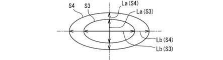
噴孔垂直断面は、流入口から流出口にかけて、短軸(La)と長軸(Lb)を有する楕円形状のまま徐々に面積拡大していく形状であり、
噴孔は、流入口から流出口にかけて、短軸の長さと長軸の長さとの比率を不変とする形状である燃料噴射弁とされる。
In order to achieve the above object, a second aspect disclosed includes a nozzle body (20) having an injection hole (31) capable of injecting fuel, and a fuel passage (18) communicating with the injection hole, and opening and closing the fuel passage. And a needle (40) for switching between fuel injection from the injection hole and injection stop,
A virtual line extending along the center of the injection hole is called an injection hole axis (C3), and a cross section of the injection hole perpendicular to the injection hole axis is called an injection hole vertical cross section (S1, S2, S3, S4). To
The vertical cross section of the injection hole is a shape in which the area gradually increases from the inflow port to the outflow port while maintaining an elliptical shape having a short axis (La) and a long axis (Lb),
The injection hole is a fuel injection valve having a shape in which the ratio of the length of the short axis to the length of the long axis is constant from the inlet to the outlet.
上記第2の態様では、噴孔垂直断面は、流入口から流出口にかけて、楕円形状のまま徐々に面積拡大していく形状であり、噴孔は、流入口から流出口にかけて、短軸の長さと長軸の長さとの比率を不変とする形状である。そのため、噴孔垂直断面の形状が噴孔軸上の位置に応じて複雑に変化していく従来の形状に比べて、噴孔軸上の位置に応じた噴孔垂直断面の形状を、所望の形状に加工することが容易になる。よって、噴孔形状の精度悪化による噴霧形状の精度悪化を抑制しつつ、噴孔を、徐々に面積拡大していく形状かつ楕円形状にすることが実現可能となる。 In the second aspect, the vertical cross section of the injection hole has a shape that gradually increases in area while maintaining an elliptical shape from the inflow port to the outflow port, and the injection hole has a short axis length from the inflow port to the outflow port. And the ratio of the length of the long axis to the length of the long axis is invariable. Therefore, compared to the conventional shape in which the shape of the injection hole vertical cross section changes in a complicated manner according to the position on the injection hole axis, the shape of the injection hole vertical cross section corresponding to the position on the injection hole axis is a desired shape. Processing into a shape is facilitated. Therefore, it is possible to realize a shape in which the injection hole gradually increases in area and an elliptical shape while suppressing the deterioration in accuracy of the spray shape due to the deterioration in accuracy of the injection hole shape.
特に、ノズルボディの板厚にばらつきに起因して噴孔の流入口における噴孔垂直断面(流入口断面)の形状がばらつくことが、上述の如く短軸/長軸比率を不変にすることで抑制されるので、噴霧形状の精度悪化を効果的に抑制できる。 In particular, the fact that the shape of the cross section perpendicular to the injection hole (inlet cross section) at the inlet of the injection hole due to the variation in the plate thickness of the nozzle body varies, as described above, by making the ratio of the minor axis / major axis unchanged. As a result, the deterioration of the accuracy of the spray shape can be effectively suppressed.
尚、上記括弧内の参照番号は、後述する実施形態における具体的な構成との対応関係の一例を示すものにすぎず、技術的範囲を何ら制限するものではない。 It should be noted that the reference numbers in the parentheses merely show an example of a correspondence relationship with a specific configuration in the embodiment described later, and do not limit the technical scope at all.
以下、本開示の複数の実施形態を図面に基づいて説明する。尚、各実施形態において対応する構成要素には同一の符号を付すことにより、重複する説明を省略する場合がある。各実施形態において構成の一部分のみを説明している場合、当該構成の他の部分については、先行して説明した他の実施形態の構成を適用することができる。 Hereinafter, a plurality of embodiments of the present disclosure will be described with reference to the drawings. In addition, in each embodiment, the same components are denoted by the same reference numerals, and redundant description may be omitted. When only a part of the configuration is described in each embodiment, the configuration of another embodiment described earlier can be applied to the other part of the configuration.
(第1実施形態)
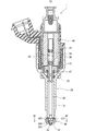
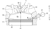
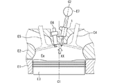
図1に示す燃料噴射弁1は、図2に示す点火着火式の車両用内燃機関(エンジンE)に取り付けられている。エンジンEは、シリンダE1、シリンダヘッドE2およびピストンE3を備える。シリンダヘッドE2には、吸気弁E4、排気弁E5、点火プラグE6および燃料噴射弁1が取り付けられている。吸気弁E4および排気弁E5は2つずつ取り付けられている。点火プラグE6は、ピストンE3の中心軸線C1上に配置されている。
(1st Embodiment)
The
燃料噴射弁1は、中心軸線C1に対して吸気弁E4側、かつ、吸気弁E4に対してピストンE3側に配置され、燃焼室Eaの側方から燃焼室Eaへ直接燃料を噴射するサイド直噴式である。したがって、燃料噴射弁1の中心線C2は、ピストンE3の中心軸線C1に対して45度以上の角度で交差する。図2中の上下方向を示す矢印は、エンジンEが車両に搭載された状態における上下方向を示すものではなく、ピストンE3の中心軸線C1方向における圧縮側を上方、膨張側を下方と表記するものである。
The
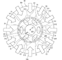
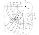
図1、図3および図4に示すように、燃料噴射弁1は、燃料を噴射する複数の噴孔31を備える。噴孔31の流入口311は、燃料噴射弁1の中心線C2の周りに同心円状に配置されている。噴孔31の流入口311の中心から噴孔31の流出口312の中心に向けて延びる噴孔31の仮想中心線を、後に詳述する噴孔軸C3と呼ぶ。全ての噴孔31について、流出口312から噴射される燃料(噴霧)の向きが、吸気弁E4側からピストンE3側へ向かう向きとなっている。全ての噴孔軸C3は、図2に示す水平方向から見て、吸気弁E4側からピストンE3側へ向かう向きとなっている。
As shown in FIGS. 1, 3 and 4, the
燃料噴射弁1は、ノズルボディ20、ニードル40、可動コア47、固定コア44、コイル38、スプリング24、26などを備える。可動コア47、固定コア44及びコイル38は、ニードル40を開閉駆動させる駆動部として機能する。デリバリパイプE7(図2参照)から燃料噴射弁1へ供給される高圧燃料は、ノズルボディ20の内部に形成された燃料通路18を流通し、噴孔31から噴射される。
The
ノズルボディ20は、第1筒部材21、第2筒部材22、第3筒部材23、及び、噴射ノズル30を備える。第1筒部材21、第2筒部材22及び第3筒部材23は、いずれも略円筒状の部材であって、第1筒部材21、第2筒部材22、第3筒部材23の順に同軸となるよう配置され、互いに接続している。
The
噴射ノズル30は、第1筒部材21の第2筒部材22とは反対側の端部に設けられている。噴射ノズル30は、有底筒状の部材であって、第1筒部材21に溶接されている。噴射ノズル30は、所定の硬度を有するよう焼入れ処理が施されている。噴射ノズル30は、噴射部301及び筒部302から形成されている。
The
ニードル40は、中心線C2方向に往復移動可能な状態でノズルボディ20内に収容されており、筒部302は、ニードル40の外面との間に円筒形状の環状通路305を形成する。環状通路305は、中心線C2の周りに環状に延びて中心線C2の延びる方向へ燃料を流通させる。
The
噴射部301は、噴射ノズル30の中心線C2上の点を中心とした中空の半球状の部位である。噴射部301は、ニードル40先端の外面との間に半球形状の分配通路303(サック室)を形成する。分配通路303の上流端は環状通路305の下流端と連通し、分配通路303の下流端は噴孔31の流入口311と連通する。
The
分配通路303は、環状通路305を流通して環状に分布する燃料を集合させ、その集合させた燃料を複数の流入口311へ分配する。図4中の矢印は、環状通路305から分配通路303へ流入する燃料の流れ方向を示し、径方向の外側から中心線C2に向かって流れる。このように流れる燃料の一部は噴孔31の流入口311へ直接流入し、他の一部は、分配通路303に溜められた後に流入口311へ流入する。環状通路305および分配通路303は、先述した燃料通路18の一部を構成する。
The
筒部302の内壁面には、ニードル40が当接可能な環状の弁座304が形成されている。ニードル40が弁座304に着座することで、環状通路305は閉鎖(閉弁)され、噴孔31からの燃料噴射が停止される。ニードル40が弁座304から離座することで、環状通路305は解放(開弁)され、噴孔31から燃料が噴射される。
An
可動コア47は、磁気安定化処理が施されている略円筒状の部材であり、ニードル40に係合している。固定コア44は、磁気安定化処理が施されている略円筒状の部材である。固定コア44は、ノズルボディ20の第3筒部材23と溶接され、ノズルボディ20の内側に固定されている。
The movable core 47 is a substantially cylindrical member subjected to a magnetic stabilization process, and is engaged with the
コイル38は、略円筒状の部材であって、主に第2筒部材22及び第3筒部材23の径方向外側を囲むよう設けられている。コイル38は、電力が供給されると磁界を発生し、固定コア44、可動コア47、第1筒部材21及び第3筒部材23を通る磁気回路を形成する。これにより、固定コア44と可動コア47との間に磁気吸引力が発生し、可動コア47は固定コア44に吸引され、ニードル40は開弁作動する。
The
スプリング24は、ニードル40を可動コア47とともに弁座304の方向、すなわち閉弁方向に付勢している。スプリング26は、可動コア47を弁座304とは反対の方向、すなわち開弁方向に付勢している。本実施形態では、スプリング24の付勢力は、スプリング26の付勢力に比べ大きく設定されている。これにより、コイル38に電力が供給されていない状態では、ニードル40のシール部は弁座304に当接した状態、すなわち閉弁状態となる。
The
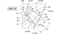
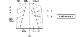
次に、図5〜図7を用いて、噴孔31の形状について詳細に説明する。以下の説明では、噴孔31のうち噴孔軸C3に対して垂直な断面を噴孔垂直断面S1、S2、S3、S4と呼ぶ。図5に示すように、流入口311および流出口312に沿う平面は、噴孔軸C3に対して垂直ではなく傾いている。図示される噴孔垂直断面S1は、噴孔31の最上流位置における断面(流入口断面)であり、流入口311の開口形状とは異なる。図示される噴孔垂直断面S4は、噴孔31の最下流位置における断面(流出口断面)であり、流出口312の開口形状とは異なる。
Next, the shape of the
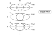
噴孔垂直断面は、噴孔軸C3方向のいずれの位置においても扁平形状であり、流入口311から流出口312にかけて相似形状のまま徐々に面積拡大していく形状である(図7参照)。具体的には、噴孔垂直断面は、流入口311から流出口312にかけて、短軸Laと長軸Lbを有する楕円形状である。短軸Laの長さと長軸Lbの長さとの比率は、噴孔軸C3方向のいずれの位置においても同一である。つまり、噴孔31は、流入口311から流出口312にかけて、短軸Laの長さと長軸Lbの長さとの比率を不変とする形状である。
The injection hole vertical cross section has a flat shape at any position in the direction of the injection hole axis C3, and has a shape that gradually increases in area from the
また、以下の説明では、噴孔31のうち噴孔軸C3を含む断面を噴孔縦断面と呼び、噴孔縦断面のうち短軸Laを含む平面を短軸平面(図5参照)と呼び、噴孔縦断面のうち長軸Lbを含む平面を長軸平面(図6参照)と呼ぶ。噴孔縦断面は、流入口311から流出口312にかけて、噴孔31の内壁面を直線的に拡大させていくテーパ形状である。
In the following description, a cross section of the
短軸平面に現れるテーパ形状のテーパ角度を短軸テーパ角度θa(図5参照)と呼び、長軸平面に現れるテーパ形状のテーパ角度を長軸テーパ角度θb(図6参照)と呼ぶ。短軸テーパ角度θaと長軸テーパ角度θbとの比率は、短軸La長さと長軸Lb長さとの比率と同一であり、θa/θb=La/Lbと表現される。 The taper angle of the taper shape appearing on the short axis plane is called a short axis taper angle θa (see FIG. 5), and the taper angle of the taper shape appearing on the long axis plane is called a long axis taper angle θb (see FIG. 6). The ratio between the minor axis taper angle θa and the major axis taper angle θb is the same as the ratio between the minor axis La length and the major axis Lb length, and is expressed as θa / θb = La / Lb.
噴孔31は、ノズルボディ20に複数形成されており、図5〜図7に示す形状は、すべての噴孔31に該当する。これらの噴孔31は、ノズルボディ20にレーザ加工を施して形成されている。
A plurality of injection holes 31 are formed in the
次に、図8〜図13を用いて、「噴孔軸C3」の定義について説明する。 Next, the definition of the “injection hole axis C3” will be described with reference to FIGS.
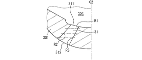
図8の一点鎖線に示すように、噴孔31の任意の3箇所の断面を設定する。これらの断面は、互いに平行であり、例えばノズルボディ20の中心線C2に対して垂直な水平断面である。図9および図10に示す実線は、これらの水平断面に現れる噴孔31の外形線R1、R2、R3である。
As shown by the dashed line in FIG. 8, three arbitrary cross sections of the
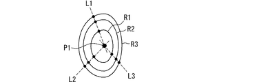
図9および図10中の点線に示す仮想直線L1、L2、L3は、3つの外形線R1、R2、R3の任意の点を通る直線である。図中の第1交点P1は、3本の仮想直線L1、L2、L3の交点である。 Virtual straight lines L1, L2, and L3 indicated by dotted lines in FIGS. 9 and 10 are straight lines passing through arbitrary points of the three outlines R1, R2, and R3. The first intersection P1 in the figure is the intersection of three virtual straight lines L1, L2, L3.
図11中の点線に示す仮想円R4は、第1交点P1からの距離が一定、かつ、噴孔31の内壁面上に位置する円である。図12中の仮想直線L4、L5の各々は、仮想円R4の円周長さを二等分する直線である。図中の第2交点P2は、2本の仮想直線L4、L5の交点である。そして、図13に示すように、第1交点P1と第2交点P2とを通る直線を、「噴孔軸C3」と定義する。
An imaginary circle R4 indicated by a dotted line in FIG. 11 is a circle having a constant distance from the first intersection P1 and located on the inner wall surface of the
以上により、本実施形態によれば、噴孔垂直断面は、楕円形状であり、かつ、噴孔31の流入口311から流出口312にかけて相似形状のまま徐々に面積拡大していく形状である。また、噴孔垂直断面は、流入口311から流出口312にかけて、楕円形状のまま徐々に面積拡大していく形状であり、噴孔31は、流入口311から流出口312にかけて、短軸Laの長さと長軸Lbの長さとの比率を不変とする形状である。
As described above, according to the present embodiment, the injection hole vertical cross section has an elliptical shape, and the area gradually increases from the
そのため、噴孔垂直断面の形状が噴孔軸C3上の位置に応じて複雑に変化していく従来の形状に比べて、噴孔軸C3上の位置に応じた噴孔垂直断面の形状を、所望の形状にレーザ加工することが容易になる。よって、噴孔形状の精度悪化による噴霧形状の精度悪化を抑制しつつ、噴孔31を、徐々に面積拡大していく形状かつ楕円形状にすることが実現可能となる。
Therefore, compared to the conventional shape in which the shape of the injection hole vertical cross section changes in a complicated manner according to the position on the injection hole axis C3, the shape of the injection hole vertical cross section corresponding to the position on the injection hole axis C3 is Laser processing into a desired shape becomes easy. Therefore, it is possible to realize a shape in which the area of the
ここで、噴孔31を流れる燃料は、噴孔垂直断面の全体を満たしつつ流れるものではなく、噴孔垂直断面のうち噴孔内壁面に沿う領域を部分的に満たしつつ流れる。つまり、噴孔31の流入口311から流入した燃料は、噴孔内壁面に沿った液膜の状態で噴孔31内を流通して流出口312から噴射される。したがって、本実施形態の如く噴孔31を楕円形状にすることで、上記液膜の薄膜化が促進される。その結果、流出口312から噴射される燃料(噴霧)の微粒化が図られるとともに、低ペネトレーション化が図られる。
Here, the fuel flowing through the
さらに、本実施形態に係る燃料噴射弁1では、噴孔垂直断面は、噴孔31の流入口311から流出口312にかけて徐々に面積拡大していく形状である。これによっても、噴霧の微粒化と低ペネトレーション化が図られている。
Furthermore, in the
次に、噴孔垂直断面の形状を所望の形状にレーザ加工することが容易になることの理由について、図14〜図21を用いて詳細に説明する。なお、図14では、理解しやすい説明にするために、噴孔垂直断面S1(流入口断面)の形状が、流入口311の開口形状と同一であるとみなして図示している。
Next, the reason why it is easy to laser-process the shape of the vertical cross section of the injection hole into a desired shape will be described in detail with reference to FIGS. In FIG. 14, for easy understanding, the shape of the injection hole vertical section S <b> 1 (inlet section) is illustrated as being the same as the opening shape of the
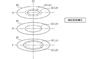
図14中の一点鎖線α、β、γは、噴射ノズル30の噴射部301の肉厚が製造ばらつきにより異なっている状態を示す。つまり、上記肉厚が薄いほど、噴孔31の噴孔軸C3方向の長さが短くなり、噴孔垂直断面S1(流入口断面)の位置が噴孔垂直断面S2(流出口断面)に近づく。図15の上段に示す実線S1(α)は、噴射部301の肉厚が一点鎖線αに示す厚さの場合における流入口断面を示す。図15の中段に示す実線S1(β)は、噴射部301の肉厚が一点鎖線βに示す厚さの場合における流入口断面を示す。図15の下段に示す実線S1(γ)は、噴射部301の肉厚が一点鎖線γに示す厚さの場合における流入口断面を示す。
The dashed lines α, β, and γ in FIG. 14 indicate a state in which the thickness of the
本実施形態に係る噴孔垂直断面の形状は、噴孔軸C3上のいずれの位置の断面であるかに拘らず相似形状であり、短軸La/長軸Lb比率は不変である。そのため、一点鎖線α、β、γに示す如く噴射部301の肉厚がばらついていても、流入口断面の形状は、大きさが異なるだけで、短軸La/長軸Lb比率は同一である(図15参照)。また、短軸テーパ角度θaと長軸テーパ角度θbとの比率は、短軸Laの長さと長軸Lbの長さとの比率と同一である。
The shape of the vertical cross section of the injection hole according to the present embodiment is similar regardless of the cross section at any position on the injection hole axis C3, and the ratio of the short axis La / the long axis Lb is unchanged. Therefore, even if the thickness of the
これに対し、図16に示す噴射ノズル30xの噴射部301xおよび噴孔31xは、本実施形態の比較例を示すものであり、噴孔垂直断面の形状が噴孔軸C3上の位置に応じて非相似的に変化していく。加えて、噴孔垂直断面の短軸/長軸比率が、噴孔軸C3上の位置に応じて変化していく。そのため、一点鎖線α、β、γに示す如く噴射部301xの肉厚がばらつくと、流入口断面の形状は、大きさが異なるとともに、短軸/長軸比率も異なってくる(図17参照)。
On the other hand, the
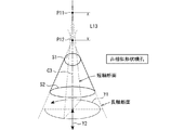
図18および図19は、本実施形態に係る噴孔31をレーザ加工するにあたり、流出口312の側から流入口311の側へ向けてレーザ光を出射した場合のレーザ光の焦点P11、P12を示す。本実施形態に係る噴孔垂直断面の形状は、噴孔軸C3上のいずれの位置の断面であるかに拘らず相似形状であり、短軸La/長軸Lb比率は不変である。そのため、以下に説明する2つの交点距離L11、L12は同じとなる。
FIGS. 18 and 19 show the laser beam processing of the injection holes 31 according to the present embodiment, in which the laser light focuses P11 and P12 when the laser light is emitted from the
交点距離L11は、短軸断面に現れる噴孔31の内壁面を延長して交差する点(焦点P11)から、噴孔垂直断面S2(流出口断面)までの距離である。交点距離L12は、長軸断面に現れる噴孔31の内壁面を延長して交差する点(焦点P12)から、噴孔垂直断面S2(流出口断面)までの距離である。
The intersection point distance L11 is a distance from a point (focal point P11) extending and intersecting the inner wall surface of the
したがって、短軸断面に現れる噴孔31の内壁面をレーザ加工するレーザ光の焦点P11と、長軸断面に現れる噴孔31の内壁面をレーザ加工するレーザ光の焦点P12とが一致する。よって、レーザ光を射出する射出ノズル(図示せず)を、噴孔軸C3方向に移動させることなく、矢印Y1に示すように同一平面上で旋回させることで、噴孔31をレーザ加工できる。
Therefore, the focal point P11 of the laser light for laser processing the inner wall surface of the
これに対し、図16に示す比較例に係る噴射ノズル30xの場合には、図20に示すように、2つの交点距離L11、L12が異なる。したがって、短軸断面に現れる噴孔31の内壁面をレーザ加工するレーザ光の焦点P11と、長軸断面に現れる噴孔31の内壁面をレーザ加工するレーザ光の焦点P12とが一致しなくなる。図21に示す例では、噴孔軸C3方向の長さL13の分、交点距離L11、L12に違いが生じている。よって、レーザ光を射出する射出ノズルを、矢印Y2に示すように噴孔軸C3方向に移動させながら、矢印Y1に示すように旋回させることで、噴孔31をレーザ加工できる。
On the other hand, in the case of the
このように、本実施形態に係る噴孔31の形状によれば、射出ノズルを、噴孔軸C3方向へ移動させずに旋回させて噴孔31をレーザ加工できる。よって、噴孔軸C3方向へ移動させながら旋回させることを要する比較例の場合に比べて、噴孔軸C3上の位置に応じて拡大していく噴孔垂直断面の形状を、所望の形状に加工することが容易になる。
As described above, according to the shape of the
また、図14〜図17を用いて説明した通り、本実施形態によれば、ノズルボディ20の板厚にばらつきに起因して噴孔31の流入口断面の形状がばらつくことが、上述の如く相似形状に形成し、かつ、短軸/長軸比率を不変にすることで抑制される。よって、噴霧形状の精度悪化を効果的に抑制できる。
In addition, as described with reference to FIGS. 14 to 17, according to the present embodiment, the shape of the cross section of the inflow port of the
また、本実施形態に係る噴孔縦断面は、流入口311から流出口312にかけて、噴孔31の内壁面を直線的に拡大させていくテーパ形状である。そのため、内壁面を曲線的に拡大させていく湾曲した形状の場合に比べて、レーザ加工を容易にできる。
The vertical cross section of the injection hole according to the present embodiment has a tapered shape in which the inner wall surface of the
また、本実施形態では、複数の噴孔31の流入口311は、ノズルボディ20の中心線C2の周りに同心円状に並べて配置されている。そして、燃料通路18は、中心線C2の周りに環状に延びて中心線C2の延びる方向へ燃料を流通させる環状通路305と、環状通路305を流通した燃料を集合させて複数の流入口311へ分配する分配通路303と、を有する。そのため、各々の噴孔31へ流入する燃料の流量を均等にすることを促進でき、流入流量むらを抑制できる。
In the present embodiment, the
(第2実施形態)
上記第1実施形態では、噴孔31の流出口312が、噴射部301の外表面上に位置している。これに対し、図22に示す本実施形態では、噴射部301の外表面301aに凹部32が形成されており、その凹部32内に噴孔31が形成されている。そのため、噴孔31の流出口312が、噴射部301の外表面301aよりも流入口311側に奥まった位置にある。このように凹部32を形成することで、噴孔31の噴孔軸C3長さを短くさせている。なお、凹部32は、噴孔軸C3と同軸に形成された円柱形状である。また、噴孔垂直断面の形状は、上記第1実施形態と同様にして、噴孔軸C3上のいずれの位置の断面であるかに拘らず相似形状であり、短軸La/長軸Lb比率は不変である。
(2nd Embodiment)
In the first embodiment, the
図22中の仮想線L20は、弁座304の表面を延長したものであり、仮想線L20の一部は噴孔31の内部に位置する。そのため、弁座304に沿って環状通路305から分配通路303へ流入する燃料(矢印Y10参照)は、噴孔31の内壁面のうち中心線C2に近い側の内壁面31aに衝突しながら流入口311へ流入する(矢印Y11参照)。そのため、内壁面31aに沿った液膜の状態で噴孔31内を流通する燃料(矢印Y12参照)の薄膜化が促進される。
A virtual line L20 in FIG. 22 is obtained by extending the surface of the
(第3実施形態)
上記第1実施形態に係る燃料噴射弁1は、図2に示すように、燃焼室Eaの側方から燃焼室Eaへ直接燃料を噴射するサイド直噴式である。これに対し、本実施形態に係る燃料噴射弁1は、図23に示すように、燃焼室Eaの上方から燃焼室Eaへ直接燃料を噴射するセンター直噴式である。具体的には、燃料噴射弁1は、吸気弁E4と排気弁E5の間に配置されており、燃料噴射弁1の中心線C2は、ピストンE3の中心軸線C1に対して45度未満の角度で交差する。
(Third embodiment)
As shown in FIG. 2, the
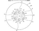
図24に示すように、複数の噴孔31の流入口311は、燃料噴射弁1の中心線C2の周りに同心円状に配置されている。全ての噴孔31について、流出口312から噴射される燃料(噴霧)の向きが、中心線C2から径方向外側に拡がる向きとなっている。全ての噴孔軸C3は、噴孔31の下流側であるほど中心線C2から離れていく向きとなっている。
As shown in FIG. 24, the
なお、本実施形態に係る噴孔垂直断面の形状は、上記第1実施形態と同様にして、噴孔軸C3上のいずれの位置の断面であるかに拘らず相似形状であり、短軸La/長軸Lb比率は不変である。 The shape of the vertical cross section of the injection hole according to the present embodiment is similar to the first embodiment, regardless of the cross section at any position on the injection hole axis C3, and the short axis La / The ratio of the long axis Lb is unchanged.
(第4実施形態)
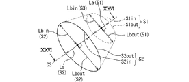
上記第1実施形態では噴孔垂直断面が楕円形状である。これに対し本実施形態では、図25に示すように、噴孔垂直断面は、流入口311から流出口312にかけて、短軸Laを共有しつつ、異なる長さの長軸Lbin、Lboutを有する2つの半楕円を合わせた形状である。2つの半楕円のうち、ノズルボディ20の中心線C2に近い側の半楕円を内側半楕円S1in、S2inと呼び、他方の側の半楕円を外側半楕円S1out、S2outと呼ぶ。そして、噴孔31は、流入口311から流出口312の全体に亘って、外側半楕円S1out、S2outの長軸Lboutが内側半楕円S1in、S2inの長軸Lbinより長くなる形状である。
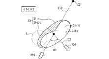
(Fourth embodiment)
In the first embodiment, the vertical cross section of the injection hole is elliptical. In contrast, in the present embodiment, as shown in FIG. 25, the injection hole vertical cross section has different lengths of the long axes Lbin and Lbout while sharing the short axis La from the
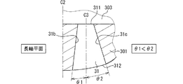
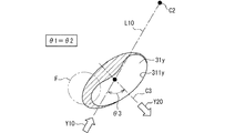
図26に示すように、短軸平面における噴孔31の形状は、噴孔軸C3を中心に左右対称である。図27に示すように、長軸平面における噴孔31の形状は、噴孔軸C3を中心に左右非対称である。以下の説明では、長軸平面において、噴孔31の内壁面のうち中心線C2に近い側の壁面を内側壁面31bと呼び、中心線C2に遠い側の壁面を外側壁面31cと呼ぶ。また、長軸平面において、内側壁面31bと噴孔軸C3とのなす角度を内側テーパ角θ1と呼び、外側壁面31cと噴孔軸C3とのなす角度を外側テーパ角θ2と呼ぶ。そして、内側テーパ角θ1は外側テーパ角θ2よりも小さい値に設定されている。なお、短軸平面においては、内側テーパ角と外側テーパ角とは同じ大きさである。
As shown in FIG. 26, the shape of the
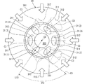
図28に示すように、中心線C2を通り噴射ノズル30の径方向に延びる線のうち、流入口311の重心または中心を通る線を仮想線L10と呼ぶ。そして、仮想線L10と噴孔軸C3とが交差する角度であって、中心線C2の方向から見た角度をねじれ角θ3と呼ぶ。
As shown in FIG. 28, among the lines extending in the radial direction of the
要するに、環状通路305から分配通路303へ流入して流入口311へ向けて流れる燃料の方向(矢印Y10参照)は、上記仮想線L10と平行である。このように流入口311へ向けて流れる燃料の方向と、流出口312からの燃料の噴射方向とは一致せず、ねじれている。このねじれ度合いを上記ねじれ角θ3は表している。
In short, the direction of fuel flowing from the
例えば、複数の噴孔31のうち噴孔31(1)のねじれ角θ3は約90度であり、噴孔31(2)のねじれ角θ3は90度未満(鋭角)であり、噴孔31(3)のねじれ角θ3は180度(鈍角)であり、噴孔31(4)のねじれ角θ3はゼロ度である。ねじれ角θ3が90度に近いほど、ねじれ度合いが大きいと言える。つまり、図28に示す4種類の噴孔31の中では、噴孔31(1)のねじれ度合いが最も大きい。 For example, among the plurality of injection holes 31, the torsion angle θ3 of the injection hole 31 (1) is about 90 degrees, and the torsion angle θ3 of the injection hole 31 (2) is less than 90 degrees (a sharp angle). The twist angle θ3 of 3) is 180 degrees (obtuse angle), and the twist angle θ3 of the injection hole 31 (4) is zero degree. It can be said that the closer the twist angle θ3 is to 90 degrees, the greater the degree of twist. That is, among the four types of injection holes 31 shown in FIG. 28, the degree of twist of the injection hole 31 (1) is the largest.
図29に示すように、ねじれ度合いが大きい噴孔31(1)では、環状通路305から分配通路303へ流入して流入口311へ向けて流れる燃料(矢印Y10参照)の分布は、矢印Y15、Y16に示すようになる。すなわち、外側半楕円S1outに流れ込む流量(矢印Y15参照)が、内側半楕円S1inに流れ込む流量(矢印Y16参照)よりも多くなる。つまり、図29中の斜線に示す領域Dへの流入流量が多くなる。
As shown in FIG. 29, in the injection hole 31 (1) having a large degree of twist, the distribution of fuel (see arrow Y10) flowing from the
図30は、本実施形態に反した形状の比較例に係る噴孔31yを流入口311y側から見た上面図である。図中の斜線は、噴孔31y内に分布する燃料を示す。図29を用いて先述した通り、外側半楕円S1outに流れ込む流量は、内側半楕円S1inに流れ込む流量よりも多くなる。よって、噴孔内壁面に沿って拡がる燃料は、外側半楕円S1outの部分に偏って分布しやすくなり、一点鎖線に示す領域Fでの液膜が厚くなりやすい。
FIG. 30 is a top view of the
これに対し、図31に示す本実施形態では、外側半楕円S1outの長軸Lboutが内側半楕円S1inの長軸Lbinより長いので、一点鎖線に示す領域Fでの燃料が壁面に沿って拡がることが促進され、液膜が厚くなることを抑制できる。また、内側テーパ角θ1が外側テーパ角θ2よりも小さい値に設定されているので、一点鎖線に示す領域Fでの燃料が壁面に沿って拡がることが促進され、液膜が厚くなることを抑制できる。 On the other hand, in the present embodiment shown in FIG. 31, since the major axis Lbout of the outer semi-ellipse S1out is longer than the major axis Lbin of the inner semi-ellipse S1in, the fuel spreads along the wall surface in the region F shown by the dashed line. Is promoted and the liquid film can be prevented from being thickened. Further, since the inner taper angle θ1 is set to a value smaller than the outer taper angle θ2, the fuel in the region F shown by the dashed line is spread along the wall surface, and the thickening of the liquid film is suppressed. it can.
このように、本実施形態によれば、噴孔31内での液膜の薄膜化を促進できるので、流出口312から噴射される燃料(噴霧)の微粒化、および低ペネトレーション化を図ることができる。
As described above, according to the present embodiment, it is possible to promote the thinning of the liquid film in the
また、本実施形態においても上記第1実施形態と同様にして、噴孔垂直断面の形状は、噴孔軸C3上のいずれの位置の断面であるかに拘らず相似形状であり、短軸La/長軸Lb比率は不変である。よって、上記第1実施形態と同様の効果が発揮される。 Also in this embodiment, similarly to the first embodiment, the shape of the injection hole vertical cross section is similar regardless of the cross section at any position on the injection hole axis C3, and the short axis La / The ratio of the long axis Lb is unchanged. Therefore, the same effect as in the first embodiment is exerted.
(他の実施形態)
以上、本開示の複数の実施形態について説明したが、各実施形態の説明において明示している構成の組み合わせばかりではなく、特に組み合わせに支障が生じなければ、明示していなくても複数の実施形態の構成同士を部分的に組み合わせることができる。そして、複数の実施形態及び変形例に記述された構成同士の明示されていない組み合わせも、以下の説明によって開示されているものとする。
(Other embodiments)
As described above, a plurality of embodiments of the present disclosure have been described. Not only the combination of configurations explicitly described in the description of each embodiment but also a plurality of embodiments even if not explicitly described unless a problem occurs in the combination. Can be partially combined. Unspecified combinations of configurations described in a plurality of embodiments and modifications are also disclosed by the following description.
・上記第1実施形態では、噴孔垂直断面は楕円形状であるが、噴孔垂直断面は、扁平した形状であれば楕円形状でなくてもよい。 In the first embodiment, the vertical cross section of the injection hole is elliptical, but the vertical cross section of the injection hole may not be elliptical as long as it is flat.
・上記第1実施形態では、噴孔縦断面は、流入口311から流出口312にかけて噴孔31の内壁面を直線的に拡大させていく、テーパ形状である。これに対し、噴孔縦断面は、流入口311から流出口312にかけて内壁面を曲線的に拡大させていく、湾曲形状であってもよい。
In the first embodiment, the vertical cross section of the injection hole has a tapered shape in which the inner wall surface of the
・上記第1実施形態では、噴孔31をレーザ加工するにあたり、流出口312の側から流入口311の側へ向けてレーザ光を出射している。これに対し、流入口311の側から流出口312の側へ向けてレーザ光を出射してレーザ加工してもよい。
In the first embodiment, when laser processing the
・上記第1実施形態では、噴孔31の数が6個であるが、6個以外の複数個であってもよく、また、1個でもよい。 In the first embodiment, the number of the injection holes 31 is six, but may be a plurality other than six, or may be one.
・上記第4実施形態では、噴孔垂直断面が相似形状、かつ、短軸La/長軸Lb比率が不変であることを前提として、外側半楕円S1out、S2outの長軸Lboutが内側半楕円S1in、S2inの長軸Lbinより長い。これに対し、外側半楕円S1out、S2outの長軸Lboutを内側半楕円S1in、S2inの長軸Lbinより長くするにあたり、噴孔垂直断面が非相似形状であってもよいし、短軸La/長軸Lb比率が変化する形状であってもよい。 In the fourth embodiment, the outer semi-ellipse S1out and the long axis Lbout of the outer semi-ellipse S2out are set to the inner semi-ellipse S1in on the premise that the injection hole vertical cross section is similar and the short axis La / long axis Lb ratio is invariant. , S2in are longer than the long axis Lbin. On the other hand, in making the major axis Lbout of the outer semi-ellipses S1out and S2out longer than the major axis Lbin of the inner semi-ellipses S1in and S2in, the vertical cross section of the injection hole may have a non-similar shape or the minor axis La / length The shape in which the axis Lb ratio changes may be used.
・上記第4実施形態では、噴孔垂直断面が相似形状、かつ、短軸La/長軸Lb比率が不変であることを前提として、内側テーパ角θ1は外側テーパ角θ2よりも小さい。これに対し、内側テーパ角θ1を外側テーパ角θ2より小さくするにあたり、噴孔垂直断面が非相似形状であってもよいし、短軸La/長軸Lb比率が変化する形状であってもよい。 In the fourth embodiment, the inner taper angle θ1 is smaller than the outer taper angle θ2 on the assumption that the injection hole vertical cross section has a similar shape and the short axis La / long axis Lb ratio does not change. On the other hand, when making the inner taper angle θ1 smaller than the outer taper angle θ2, the injection hole vertical cross section may have a non-similar shape or a shape in which the ratio of the short axis La / the long axis Lb may be changed. .
θ1 内側テーパ角、 θ2 外側テーパ角、 θa 短軸テーパ角度、 θb 長軸テーパ角度、 18 燃料通路、 20 ノズルボディ、 303 分配通路、 305 環状通路、 31 噴孔、 311 流入口、 312 流出口、 31c 外側壁面、 40 ニードル、 C2 中心線、 C3 噴孔軸、 La 短軸、 Lb 長軸、 S1 噴孔垂直断面、 S1in 内側半楕円、 S1out 外側半楕円、 S2 噴孔垂直断面、 S2in 内側半楕円、 S2out 外側半楕円、 S3、S4 噴孔垂直断面。 θ1 inner taper angle, θ2 outer taper angle, θa short axis taper angle, θb long axis taper angle, 18 fuel passage, 20 nozzle body, 303 distribution passage, 305 annular passage, 31 injection hole, 311 inflow port, 312 outflow port, 31c Outer wall surface, 40 needle, C2 center line, C3 injection hole axis, La short axis, Lb long axis, S1 injection hole vertical section, S1in inner semi-ellipse, S1out outer semi-ellipse, S2 injection hole vertical section, S2in inner semi-ellipse , S2out Outer semi-ellipse, S3, S4 Vertical cross section of the injection hole.
Claims (8)
前記燃料通路を開閉することで、前記噴孔からの燃料噴射と噴射停止とを切り替えるニードル(40)と、
を備え、
前記噴孔の中心に沿って延びる仮想線を噴孔軸(C3)と呼び、前記噴孔のうち前記噴孔軸に対して垂直な断面を噴孔垂直断面(S1、S2、S3、S4)と呼ぶ場合に、
前記噴孔垂直断面は、扁平形状であり、かつ、前記噴孔の流入口(311)から流出口(312)にかけて相似形状のまま徐々に面積拡大していく形状である燃料噴射弁。 A nozzle body (20) having an injection hole (31) capable of injecting fuel, and a fuel passage (18) communicating with the injection hole;
A needle (40) for switching between fuel injection from the injection hole and injection stop by opening and closing the fuel passage;
With
An imaginary line extending along the center of the injection hole is called an injection hole axis (C3), and a cross section of the injection hole perpendicular to the injection hole axis is an injection hole vertical cross section (S1, S2, S3, S4). When we call
A fuel injection valve, wherein the injection hole vertical cross section has a flat shape and a shape which gradually increases in area while maintaining a similar shape from an inlet (311) to an outlet (312) of the injection hole.
前記噴孔縦断面は、前記流入口から前記流出口にかけて、前記噴孔の内壁面を直線的に拡大させていくテーパ形状である請求項1に記載の燃料噴射弁。 When a cross section including the injection hole axis among the injection holes is referred to as an injection hole longitudinal section,
The fuel injection valve according to claim 1, wherein the vertical cross section of the injection hole has a tapered shape that linearly expands an inner wall surface of the injection hole from the inflow port to the outflow port.
前記燃料通路を開閉することで、前記噴孔からの燃料噴射と噴射停止とを切り替えるニードル(40)と、
を備え、
前記噴孔の中心に沿って延びる仮想線を噴孔軸(C3)と呼び、前記噴孔のうち前記噴孔軸に対して垂直な断面を噴孔垂直断面(S1、S2、S3、S4)と呼ぶ場合に、
前記噴孔垂直断面は、前記噴孔の流入口(311)から流出口(312)にかけて、短軸(La)と長軸(Lb)を有する楕円形状のまま徐々に面積拡大していく形状であり、
前記噴孔は、前記流入口から前記流出口にかけて、前記短軸の長さと前記長軸の長さとの比率を不変とする形状である燃料噴射弁。 A nozzle body (20) having an injection hole (31) capable of injecting fuel, and a fuel passage (18) communicating with the injection hole;
A needle (40) for switching between fuel injection from the injection hole and injection stop by opening and closing the fuel passage;
With
An imaginary line extending along the center of the injection hole is called an injection hole axis (C3), and a cross section of the injection hole perpendicular to the injection hole axis is an injection hole vertical cross section (S1, S2, S3, S4). When we call
The vertical cross section of the injection hole has a shape in which the area gradually increases from the inlet (311) to the outlet (312) of the injection hole while maintaining an elliptical shape having a short axis (La) and a long axis (Lb). Yes,
The fuel injection valve, wherein the injection hole has a shape in which a ratio between a length of the short axis and a length of the long axis does not change from the inflow port to the outflow port.
前記噴孔縦断面は、前記流入口から前記流出口にかけて、前記噴孔の内壁面を直線的に拡大させていくテーパ形状であり、
前記短軸平面に現れる前記テーパ形状のテーパ角度である短軸テーパ角度(θa)と、前記長軸平面に現れる前記テーパ形状のテーパ角度である長軸テーパ角度(θb)との比率は、前記短軸の長さと前記長軸の長さとの比率と同一である請求項3に記載の燃料噴射弁。 A cross section of the injection hole including the injection hole axis is referred to as an injection hole longitudinal section, a plane including the short axis of the injection hole longitudinal section is referred to as a short axis plane, and the long axis of the injection hole vertical cross section is referred to as a short axis plane. When the plane containing is called the long axis plane,
The injection hole vertical cross section is a tapered shape that linearly expands the inner wall surface of the injection hole from the inflow port to the outflow port,
The ratio of the minor axis taper angle (θa), which is the taper angle of the taper shape appearing on the minor axis plane, to the major axis taper angle (θb), which is the taper angle of the taper shape appearing on the major axis plane, is as follows. 4. The fuel injection valve according to claim 3, wherein a ratio between a length of the minor axis and a length of the major axis is the same.
複数の前記噴孔の前記流入口は、前記ノズルボディの中心線(C2)の周りに並べて配置されており、
前記燃料通路は、
前記中心線の周りに環状に延びて前記中心線の延びる方向へ燃料を流通させる環状通路(305)と、
前記環状通路を流通した燃料を集合させて複数の前記流入口へ分配する分配通路(303)と、
を有する請求項1〜4のいずれか1つに記載の燃料噴射弁。 A plurality of the injection holes are formed in the nozzle body,
The inflow ports of the plurality of injection holes are arranged side by side around a center line (C2) of the nozzle body,
The fuel passage,
An annular passageway (305) extending annularly around the centerline and allowing fuel to flow in a direction in which the centerline extends;
A distribution passage (303) for collecting the fuel flowing through the annular passage and distributing the collected fuel to the plurality of inlets;
The fuel injection valve according to any one of claims 1 to 4, comprising:
2つの前記半楕円のうち、前記中心線に近い側の半楕円を内側半楕円(S1in、S2in)と呼び、他方の側の半楕円を外側半楕円(S1out、S2out)と呼ぶ場合に、
前記噴孔は、前記外側半楕円の長軸が前記内側半楕円の長軸より長くなる形状である請求項5に記載の燃料噴射弁。 The injection hole vertical cross section, from the inflow port to the outflow port, is a shape obtained by combining two semi-ellipses having different major axis lengths while sharing the minor axis,
Of the two semi-ellipses, a semi-ellipse near the center line is called an inner semi-ellipse (S1in, S2in), and a semi-ellipse on the other side is called an outer semi-ellipse (S1out, S2out).
The fuel injection valve according to claim 5, wherein the injection hole has a shape in which a major axis of the outer semi-ellipse is longer than a major axis of the inner semi-ellipse.
前記噴孔のうち前記噴孔軸を含む断面を噴孔縦断面と呼び、前記噴孔縦断面のうち前記短軸を含む平面を短軸平面と呼び、前記噴孔縦断面のうち前記長軸を含む平面を長軸平面と呼び、前記長軸平面に現れる前記噴孔の壁面のうち前記中心線に近い側の壁面を内側壁面(31b)と呼び、前記長軸平面に現れる前記噴孔の壁面のうち前記中心線から遠い側の壁面を外側壁面(31c)と呼ぶ場合に、
前記内側壁面と前記噴孔軸とのなす角度である内側テーパ角(θ1)は、前記外側壁面と前記噴孔軸とのなす角度である外側テーパ角(θ2)よりも小さい請求項5または6に記載の燃料噴射弁。 The injection hole vertical cross section has a shape in which the area gradually increases from the inflow port to the outflow port while maintaining an elliptical shape having a short axis (La) and a long axis (Lb),
A cross section of the injection hole including the injection hole axis is referred to as an injection hole longitudinal section, a plane including the short axis of the injection hole longitudinal section is referred to as a short axis plane, and the long axis of the injection hole vertical cross section is referred to as a short axis plane. Is referred to as a long axis plane, and among the wall surfaces of the injection holes appearing in the long axis plane, a wall surface closer to the center line is referred to as an inner wall surface (31b). When a wall surface of the wall surface farther from the center line is referred to as an outer wall surface (31c),
7. An inner taper angle (.theta.1) that is an angle between the inner wall surface and the injection hole axis is smaller than an outer taper angle (.theta.2) that is an angle between the outer wall surface and the injection hole axis. A fuel injection valve according to claim 1.
Priority Applications (5)
| Application Number | Priority Date | Filing Date | Title |
|---|---|---|---|
| JP2018132562A JP2020008013A (en) | 2018-07-12 | 2018-07-12 | Fuel injection valve |
| DE112019003552.5T DE112019003552T5 (en) | 2018-07-12 | 2019-05-16 | Fuel injector |
| CN201980045949.4A CN112368475B (en) | 2018-07-12 | 2019-05-16 | Fuel injection valve |
| PCT/JP2019/019426 WO2020012778A1 (en) | 2018-07-12 | 2019-05-16 | Fuel injection valve |
| US17/142,631 US11835020B2 (en) | 2018-07-12 | 2021-01-06 | Fuel injection valve |
Applications Claiming Priority (1)
| Application Number | Priority Date | Filing Date | Title |
|---|---|---|---|
| JP2018132562A JP2020008013A (en) | 2018-07-12 | 2018-07-12 | Fuel injection valve |
Publications (2)
| Publication Number | Publication Date |
|---|---|
| JP2020008013A true JP2020008013A (en) | 2020-01-16 |
| JP2020008013A5 JP2020008013A5 (en) | 2020-10-01 |
Family
ID=69141515
Family Applications (1)
| Application Number | Title | Priority Date | Filing Date |
|---|---|---|---|
| JP2018132562A Pending JP2020008013A (en) | 2018-07-12 | 2018-07-12 | Fuel injection valve |
Country Status (5)
| Country | Link |
|---|---|
| US (1) | US11835020B2 (en) |
| JP (1) | JP2020008013A (en) |
| CN (1) | CN112368475B (en) |
| DE (1) | DE112019003552T5 (en) |
| WO (1) | WO2020012778A1 (en) |
Cited By (1)
| Publication number | Priority date | Publication date | Assignee | Title |
|---|---|---|---|---|
| WO2022014426A1 (en) * | 2020-07-14 | 2022-01-20 | 株式会社デンソー | Fuel injection valve |
Families Citing this family (1)
| Publication number | Priority date | Publication date | Assignee | Title |
|---|---|---|---|---|
| US11098686B2 (en) * | 2017-05-12 | 2021-08-24 | Hitachi Automotive Systems, Ltd. | Fuel injection valve |
Citations (2)
| Publication number | Priority date | Publication date | Assignee | Title |
|---|---|---|---|---|
| JP2017025926A (en) * | 2016-09-23 | 2017-02-02 | 株式会社デンソー | Fuel injection valve |
| JP2017061935A (en) * | 2016-11-04 | 2017-03-30 | 日立オートモティブシステムズ株式会社 | Fuel injection valve |
Family Cites Families (22)
| Publication number | Priority date | Publication date | Assignee | Title |
|---|---|---|---|---|
| EP1128062B1 (en) * | 2000-02-25 | 2006-04-26 | Denso Corporation | Fluid injection nozzle |
| DE10116714A1 (en) * | 2001-04-04 | 2002-10-10 | Volkswagen Ag | Fuel injection valve for internal combustion engine, preferably for high jet speeds, has spray channels with cross-sections that expand after jet hole |
| US6817545B2 (en) * | 2002-01-09 | 2004-11-16 | Visteon Global Technologies, Inc. | Fuel injector nozzle assembly |
| DE102004005526B4 (en) | 2003-02-05 | 2022-03-31 | Denso Corporation | Fuel injector of an internal combustion engine |
| JP2006002720A (en) | 2004-06-21 | 2006-01-05 | Mitsubishi Electric Corp | Fuel injection device and method for manufacturing the same |
| JP4134966B2 (en) | 2004-08-17 | 2008-08-20 | 株式会社デンソー | Injection hole member, fuel injection valve, and method for manufacturing injection hole member |
| JP4221726B2 (en) * | 2005-04-01 | 2009-02-12 | 株式会社デンソー | Injection hole plate and fuel injection valve |
| FR2889258A3 (en) * | 2005-07-29 | 2007-02-02 | Renault Sas | Fuel injector for motor vehicle, has hollow lower injection dome comprising outer surface with portion truncated around outlet orifice of injection channel such that thickness of dome is reduced in zone of channel |
| JP2008064038A (en) * | 2006-09-07 | 2008-03-21 | Denso Corp | Fuel injection device |
| JP4906466B2 (en) * | 2006-10-16 | 2012-03-28 | 日立オートモティブシステムズ株式会社 | Fuel injection valve and fuel injection device for internal combustion engine equipped with the same |
| JP2010112196A (en) | 2008-11-04 | 2010-05-20 | Keihin Corp | Nozzle of fuel injection valve |
| JP5605325B2 (en) | 2011-07-19 | 2014-10-15 | トヨタ自動車株式会社 | Fuel injection valve |
| JP5772495B2 (en) | 2011-10-21 | 2015-09-02 | トヨタ自動車株式会社 | Fuel injection valve |
| JP5842728B2 (en) * | 2012-05-08 | 2016-01-13 | 株式会社日本自動車部品総合研究所 | Fuel injection valve |
| JP6044425B2 (en) * | 2013-04-02 | 2016-12-14 | トヨタ自動車株式会社 | Fuel injection valve |
| JP6042765B2 (en) | 2013-04-23 | 2016-12-14 | 株式会社日本自動車部品総合研究所 | Fuel injection valve |
| JP6020380B2 (en) * | 2013-08-02 | 2016-11-02 | 株式会社デンソー | Fuel injection valve |
| JP2015209772A (en) * | 2014-04-24 | 2015-11-24 | 三菱電機株式会社 | Fluid injection valve, spay generation device including the same, and engine |
| JP6460858B2 (en) * | 2015-03-17 | 2019-01-30 | 株式会社エンプラス | Nozzle plate for fuel injector |
| WO2016163086A1 (en) * | 2015-04-09 | 2016-10-13 | 株式会社デンソー | Fuel injection device |
| JP6501642B2 (en) | 2015-06-15 | 2019-04-17 | 株式会社Soken | Fuel injection valve |
| JP6463286B2 (en) * | 2016-02-15 | 2019-01-30 | 株式会社Soken | Fuel injection valve |
-
2018
- 2018-07-12 JP JP2018132562A patent/JP2020008013A/en active Pending
-
2019
- 2019-05-16 DE DE112019003552.5T patent/DE112019003552T5/en active Pending
- 2019-05-16 CN CN201980045949.4A patent/CN112368475B/en active Active
- 2019-05-16 WO PCT/JP2019/019426 patent/WO2020012778A1/en active Application Filing
-
2021
- 2021-01-06 US US17/142,631 patent/US11835020B2/en active Active
Patent Citations (2)
| Publication number | Priority date | Publication date | Assignee | Title |
|---|---|---|---|---|
| JP2017025926A (en) * | 2016-09-23 | 2017-02-02 | 株式会社デンソー | Fuel injection valve |
| JP2017061935A (en) * | 2016-11-04 | 2017-03-30 | 日立オートモティブシステムズ株式会社 | Fuel injection valve |
Cited By (2)
| Publication number | Priority date | Publication date | Assignee | Title |
|---|---|---|---|---|
| WO2022014426A1 (en) * | 2020-07-14 | 2022-01-20 | 株式会社デンソー | Fuel injection valve |
| DE112021003797T5 (en) | 2020-07-14 | 2023-05-17 | Denso Corporation | fuel injector |
Also Published As
| Publication number | Publication date |
|---|---|
| DE112019003552T5 (en) | 2021-04-01 |
| US11835020B2 (en) | 2023-12-05 |
| CN112368475B (en) | 2023-02-10 |
| WO2020012778A1 (en) | 2020-01-16 |
| CN112368475A (en) | 2021-02-12 |
| US20210123403A1 (en) | 2021-04-29 |
Similar Documents
| Publication | Publication Date | Title |
|---|---|---|
| JP4022882B2 (en) | Fuel injection device | |
| US9194351B2 (en) | Injection valve | |
| US20050087630A1 (en) | Unitary fluidic flow controller orifice disc for fuel injector | |
| KR19990045584A (en) | Fuel injection valve | |
| US10352231B2 (en) | Internal combustion engine | |
| JP6292188B2 (en) | Fuel injection device | |
| US20170321636A1 (en) | Gas injector including an outwardly opening valve closure element | |
| WO2020012778A1 (en) | Fuel injection valve | |
| JP2008255912A (en) | Cylinder injection internal combustion engine and fuel injection method for cylinder injection internal combustion engine | |
| JP4306656B2 (en) | Fuel injection valve | |
| JP2011226334A (en) | Fuel injection valve | |
| JP2010151053A (en) | Fuel injection nozzle | |
| US6820826B2 (en) | Spray targeting to an arcuate sector with non-angled orifices in fuel injection metering disc and method | |
| JP4519162B2 (en) | Internal combustion engine | |
| EP2677158B1 (en) | Fuel injector of internal combustion engine | |
| JP2003184706A (en) | Fuel injection valve | |
| JP2008038716A (en) | Fuel injection valve | |
| JP6841245B2 (en) | Internal combustion engine | |
| JP7272645B2 (en) | fuel injector | |
| JP6771403B2 (en) | Fuel injection device | |
| JP6654875B2 (en) | Fuel injection valve | |
| JP2010216412A (en) | Fuel injection valve | |
| WO2020255943A1 (en) | Fuel injection valve | |
| WO2022024497A1 (en) | Fuel injection device | |
| WO2018207582A1 (en) | Fuel injection valve |
Legal Events
| Date | Code | Title | Description |
|---|---|---|---|
| A521 | Request for written amendment filed |
Free format text: JAPANESE INTERMEDIATE CODE: A523 Effective date: 20200824 |
|
| A621 | Written request for application examination |
Free format text: JAPANESE INTERMEDIATE CODE: A621 Effective date: 20210524 |
|
| A131 | Notification of reasons for refusal |
Free format text: JAPANESE INTERMEDIATE CODE: A131 Effective date: 20220412 |
|
| A521 | Request for written amendment filed |
Free format text: JAPANESE INTERMEDIATE CODE: A523 Effective date: 20220609 |
|
| A131 | Notification of reasons for refusal |
Free format text: JAPANESE INTERMEDIATE CODE: A131 Effective date: 20221018 |
|
| A02 | Decision of refusal |
Free format text: JAPANESE INTERMEDIATE CODE: A02 Effective date: 20230411 |