WO2022024497A1 - Fuel injection device - Google Patents
Fuel injection device Download PDFInfo
- Publication number
- WO2022024497A1 WO2022024497A1 PCT/JP2021/018150 JP2021018150W WO2022024497A1 WO 2022024497 A1 WO2022024497 A1 WO 2022024497A1 JP 2021018150 W JP2021018150 W JP 2021018150W WO 2022024497 A1 WO2022024497 A1 WO 2022024497A1
- Authority
- WO
- WIPO (PCT)
- Prior art keywords
- hole
- fuel
- injection
- injection hole
- sack chamber
- Prior art date
Links
Images


Classifications
-
- F—MECHANICAL ENGINEERING; LIGHTING; HEATING; WEAPONS; BLASTING
- F02—COMBUSTION ENGINES; HOT-GAS OR COMBUSTION-PRODUCT ENGINE PLANTS
- F02M—SUPPLYING COMBUSTION ENGINES IN GENERAL WITH COMBUSTIBLE MIXTURES OR CONSTITUENTS THEREOF
- F02M61/00—Fuel-injectors not provided for in groups F02M39/00 - F02M57/00 or F02M67/00
- F02M61/16—Details not provided for in, or of interest apart from, the apparatus of groups F02M61/02 - F02M61/14
- F02M61/18—Injection nozzles, e.g. having valve seats; Details of valve member seated ends, not otherwise provided for
- F02M61/188—Spherical or partly spherical shaped valve member ends
-
- F—MECHANICAL ENGINEERING; LIGHTING; HEATING; WEAPONS; BLASTING
- F02—COMBUSTION ENGINES; HOT-GAS OR COMBUSTION-PRODUCT ENGINE PLANTS
- F02M—SUPPLYING COMBUSTION ENGINES IN GENERAL WITH COMBUSTIBLE MIXTURES OR CONSTITUENTS THEREOF
- F02M61/00—Fuel-injectors not provided for in groups F02M39/00 - F02M57/00 or F02M67/00
- F02M61/16—Details not provided for in, or of interest apart from, the apparatus of groups F02M61/02 - F02M61/14
- F02M61/18—Injection nozzles, e.g. having valve seats; Details of valve member seated ends, not otherwise provided for
- F02M61/1806—Injection nozzles, e.g. having valve seats; Details of valve member seated ends, not otherwise provided for characterised by the arrangement of discharge orifices, e.g. orientation or size
- F02M61/182—Discharge orifices being situated in different transversal planes with respect to valve member direction of movement
-
- F—MECHANICAL ENGINEERING; LIGHTING; HEATING; WEAPONS; BLASTING
- F02—COMBUSTION ENGINES; HOT-GAS OR COMBUSTION-PRODUCT ENGINE PLANTS
- F02M—SUPPLYING COMBUSTION ENGINES IN GENERAL WITH COMBUSTIBLE MIXTURES OR CONSTITUENTS THEREOF
- F02M61/00—Fuel-injectors not provided for in groups F02M39/00 - F02M57/00 or F02M67/00
- F02M61/16—Details not provided for in, or of interest apart from, the apparatus of groups F02M61/02 - F02M61/14
- F02M61/18—Injection nozzles, e.g. having valve seats; Details of valve member seated ends, not otherwise provided for
- F02M61/1806—Injection nozzles, e.g. having valve seats; Details of valve member seated ends, not otherwise provided for characterised by the arrangement of discharge orifices, e.g. orientation or size
- F02M61/1833—Discharge orifices having changing cross sections, e.g. being divergent
Definitions
- the present invention relates to a fuel injection device.
- Patent Document 1 describes a technique relating to a fuel injection device including a valve body and an injection hole forming portion in which a plurality of injection holes for injecting fuel are formed on the tip end side of the valve body. Further, in Patent Document 1, the injection hole forming portion includes a first injection hole in which the intersection angle between the central axis of the injection hole forming portion and the first injection hole axis is ⁇ 1, and the central axis and the first injection hole forming portion. It is described that a second injection hole having a crossing angle with the injection hole axis of ⁇ 2 larger than ⁇ 1 is formed.
- the fuel during or after injection tends to adhere to the tip of the fuel injection device.
- the fuel adhering to the tip portion is not considered.
- the technique described in Patent Document 1 has a problem that the fuel adhering to the tip portion becomes soot, which tends to generate a bright flame and deteriorates the exhaust gas performance.
- the purpose of the present invention is to provide a fuel injection device capable of suppressing fuel from adhering to the surface of the tip portion and improving combustion stability in consideration of the above problems.
- the fuel injection device includes a nozzle body, an injection hole forming member, and a valve body.
- the nozzle body is installed in the cylinder of the internal combustion engine in which the spark plug is arranged.
- the injection hole forming member is provided at the tip of the nozzle body.
- the valve body is formed with a valve body side seat surface that comes into contact with and separates from the seat surface provided on the injection hole forming member.
- the injection hole forming member has a seat portion having a seat surface and a sack chamber formed at the tip portion of the seat portion and recessed from the seat surface toward the tip portion side.
- the sack chamber is formed with a sack chamber injection hole for injecting fuel toward the spark plug.
- the fuel injection device having the above configuration, it is possible to suppress the adhesion of fuel to the surface of the tip portion and improve the stability of combustion.
- FIGS. 1 to 7 The common members in each figure are designated by the same reference numerals.
- FIG. 1 is an exploded perspective view showing a fuel injection device.
- the fuel injection device shown in FIG. 1 is used as an internal combustion engine in a four-cycle engine that repeats four strokes of an entry stroke, a compression stroke, a combustion (expansion) stroke, and an exhaust stroke. Further, the fuel injection device is applied to an in-cylinder injection type internal combustion engine that injects fuel into the cylinders of each cylinder.
- the fuel injection device 1 includes a nozzle body 10, a valve body 20, a movable core 30, a fixed core 40, a coil 50, a housing 70, a connection portion 80, a filter 90, and the like. It is equipped with. Further, the fuel injection device 1 includes a first spring 61, a second spring 63, and an adjusting member 62.
- the nozzle body 10 is formed in a cylindrical shape.
- a first internal space 130 is formed at the tip end portion, which is one end of the axial direction Da "hereinafter, simply referred to as” axial direction Da "" along the central axis AX1 of the nozzle body 10.
- a large diameter portion 14 having an outer diameter larger than that of the tip portion is formed at the rear end portion which is the other end portion of the nozzle body 10 in the axial direction Da.
- a second internal space 140 is formed in the large diameter portion 14. The first internal space 130 and the second internal space 140 are communicated with each other by a communication hole 16 formed along the axial direction Da of the nozzle body 10.
- the first internal space 130 is a concave portion recessed from the tip end portion of the nozzle body 10 toward the inside of the axial direction Da.
- An injection hole forming member 12 is attached to the first internal space 130 by insertion or press fitting. Further, the injection hole forming member 12 is fixed to the nozzle body 10 by being welded over the entire circumference at the inner peripheral edge of the opening at the tip of the nozzle body 10. A plurality of injection holes 18 and 19 for injecting fuel are formed in the injection hole forming member 12. The detailed configuration of the injection hole forming member 12 and the injection holes 18 and 19 will be described later.
- a plurality of (two in this example) grooves 131 are formed on the outer peripheral surface of the nozzle body 10 on the tip end side.
- the groove 131 is continuously formed along the circumferential direction of the outer peripheral surface of the nozzle body 10.
- a sealing member 15 is fitted in the groove 131. The seal member 15 seals the gap between the cylinder 301 and the fuel injection device 1 when the fuel injection device 1 is attached to the cylinder 301 (see FIG. 2) of the internal combustion engine.
- the second internal space 140 is a bottomed recess in which the rear end side of the large diameter portion 14 is open and recessed toward the tip end side in the axial direction Da.
- a movable core 30 described later and a part of the fixed core 40 are arranged in the second internal space 140.
- a spring accommodating portion 141 formed concentrically with the second internal space 140 is formed in the central portion of the bottom portion of the second internal space 140.
- the spring accommodating portion 141 is a concave portion recessed in a cylindrical shape from the bottom portion of the second internal space 140 toward the tip end portion.
- One end of the second spring 63 is accommodated in the spring accommodating portion 141.
- valve body 20 Inside the nozzle body 10, the valve body 20 is movably arranged along the axial direction Da.
- the valve body 20 is formed in a columnar shape.
- the valve body 20 has a rear end portion 21, a tip portion 23, and an intermediate portion 22 indicating an intermediate portion between the rear end portion 21 and the tip portion 23.
- the tip portion 23 is formed on the front end side of the valve body 20 in the axial direction Da
- the rear end portion 21 is formed on the rear end side of the valve body 20 in the axial direction Da.
- the tip portion 23 is housed in an injection hole forming member 12 provided at the tip portion of the nozzle body 10.
- the tip portion 23 opens and closes the injection holes 18 and 19 provided in the injection hole forming member 12 by the valve body 20 moving along the axial direction Da.
- the detailed configuration of the tip portion 23 will be described later.
- the intermediate portion 22 is continuously provided from the rear end side of the tip portion 23 in the axial direction Da.
- the intermediate portion 22 is arranged in the communication hole 16 of the nozzle body 10.
- a gap G1 is formed between the outer peripheral surface 221 of the intermediate portion 22 and the inner peripheral surface of the communication hole 16.
- the rear end portion 21 is continuously provided from the rear end side of the intermediate portion 22 in the axial direction Da.
- the rear end portion 21 is arranged in the second internal space 140 in the nozzle body 10.
- the rear end portion 21 is formed in a substantially columnar shape larger than the outer diameter of the intermediate portion 22.
- the rear end portion 21 is inserted into the tubular hole of the fixed core 40 described later.
- the rear end portion 21 is provided with a rear end side sliding portion 211, a plurality of flow path forming portions 212, and an engaging portion 213.
- the rear end side sliding portion 211 is formed on the outer peripheral surface of the rear end portion 21.
- the rear end side sliding portion 211 is slidably supported on the inner peripheral surface 41 of the fixed core 40 described later.
- the valve body 20 is movably supported by the fixed core 40 along the axial direction Da.
- the plurality of flow path forming portions 212 are formed by notching a plurality of outer peripheral surfaces of the rear end portion 21 along the axial direction Da. Then, the flow path forming portion 212 forms a flow path FC through which fuel passes between the inner peripheral surface 41 of the fixed core 40 described later.
- the engaging portion 213 is provided on the tip end side in the axial direction Da with respect to the flow path forming portion 212 provided on the rear end portion 21.
- the engaging portion 213 projects radially outward from the outer peripheral surface of the rear end portion 21.
- the engaging portion 213 engages with the movable core 30, which will be described later, when the on-off valve of the valve body 20 operates.
- first spring 61 is in contact with the end surface of the rear end 21 on the rear end side in the axial direction Da.
- the valve body 20 is urged by the first spring 61 toward the tip end side (valve closed side) in the axial direction Da.
- the valve body 20 having the above-mentioned structure is made of a metal material such as SUS.
- the movable core 30 is arranged in the second internal space 140 of the nozzle body 10 between the rear end portion 21 of the valve body 20 and the bottom portion of the second internal space 140. Further, a minute gap G3 is formed between the outer peripheral surface of the movable core 30 and the inner peripheral surface of the second internal space. Therefore, the movable core 30 is movably arranged along the axial direction Da in the second internal space 140.
- the movable core 30 is formed in a cylindrical shape.
- the movable core 30 is formed with an insertion hole 31 and an eccentric through hole 32.
- the insertion hole 31 and the eccentric through hole 32 are through holes that penetrate from one end to the other end of the axial direction Da in the movable core 30.
- the insertion hole 31 is formed on the central axis of the movable core 30. The intermediate portion 22 of the valve body 20 is inserted into the insertion hole 31.
- the eccentric through hole 32 is formed at a position eccentric from the central axis of the movable core 30.
- the eccentric through hole 32 communicates with the flow path FC formed by the flow path forming portion 212 and the inner peripheral surface 41 of the fixed core 40.
- the eccentric through hole 32 forms a flow path FC through which the fuel passes.
- the other end of the second spring 63 is in contact with the end surface of the movable core 30 on the tip end side in the axial direction Da. Therefore, the second spring 63 is interposed between the movable core 30 and the spring accommodating portion 141 of the nozzle body 10. Further, the fixed core 40 is in contact with the end surface of the movable core 30 on the rear end side in the axial direction Da.
- the fixed core 40 is a member that attracts the movable core 30 by magnetic attraction.
- the fixed core 40 is formed in a substantially cylindrical shape having irregularities on the outer peripheral surface.
- the tip of the axial Da in the fixed core 40 is press-fitted into the inside of the large diameter portion 14 of the nozzle body 10, that is, into the second internal space 140.
- the nozzle body 10 and the fixed core 40 are joined by welding. As a result, the gap between the nozzle body 10 and the fixed core 40 is sealed, and the space inside the nozzle body 10 is sealed.
- the tip end portion of the fixed core 40 faces the end surface on the rear end side of the axial direction Da in the movable core 30 arranged in the second internal space 140.
- the opposite tip portions of the movable core 30 in the fixed core 40 may be coated with plating such as hard chrome plating or electroless nickel plating. This makes it possible to improve the durability and reliability of the tip portion of the fixed core 40 with which the movable core 30 collides.
- the rear end portion of the movable core 30 facing the fixed core 40 may be coated with plating such as hard chrome plating or electroless nickel plating.
- the rear end side of the axial Da in the fixed core 40 protrudes from the second internal space 140 of the nozzle body 10 toward the rear end of the axial Da.
- a through hole 42 is formed in the fixed core 40.
- the through hole 42 is formed coaxially with the central axis AX1. Then, the through hole 42 forms a flow path FC through which the fuel passes. Further, an opening 43 communicating with the through hole 42 is formed at the rear end portion of the fixed core 40 in the axial direction Da. Fuel is introduced from the opening 43 toward the through hole 42. Further, the filter 90 is inserted from the opening 43 to the through hole 42.
- first spring 61 and the adjusting member 62 are arranged on the tip end side of the axial direction Da in the through hole 42.
- the first spring 61 is arranged on the tip end side of the through hole 42 with respect to the adjusting member 62.
- the adjusting member 62 is press-fitted into the through hole 42 and fixed inside the fixed core 40. Further, the rear end portion 21 of the valve body 20 is inserted from the tip end portion of the through hole 42.
- the first spring 61 is interposed between the adjusting member 62 and the rear end portion 21 of the valve body 20. Then, the first spring 61 urges the valve body 20 toward the tip of the nozzle body 10 in the axial direction Da.
- the urging force of the valve body 20 in the first spring 61 can be adjusted. Thereby, the initial load that the tip portion 23 of the valve body 20 presses against the seat surface 124a provided on the injection hole forming member 12 described later of the nozzle body 10 can be adjusted.
- the urging force by which the first spring 61 urges the valve body 20 toward the tip of the nozzle body 10 is larger than the urging force by which the second spring 63 urges the movable core 30 toward the fixed core 40. It is set large.
- the coil 50 is wound around a cylindrical coil bobbin 51.
- the coil 50 is wound around the coil bobbin 51 and is arranged so as to cover a part of the outer peripheral surface of the large diameter portion 14 of the nozzle body 10 and a part of the outer peripheral surface of the tip end portion of the fixed core 40.
- the winding start and winding end ends of the coil 50 are connected to the power supply terminal 811 of the connector 81 of the connection portion 80, which will be described later, via wiring (not shown).
- a housing 70 is fixed to the outer periphery of the coil 50 and the coil bobbin 51.
- the housing 70 is formed in a bottomed cylindrical shape.
- a through hole 71 is formed in the bottom portion of the housing 70, which is the tip end portion in the axial direction Da.
- the through hole 71 is formed in the central portion of the bottom portion.
- the large diameter portion 14 of the nozzle body 10 is inserted into the through hole 71. Then, for example, the opening edge of the through hole 71 and the outer peripheral surface of the nozzle body 10 are welded over the entire circumference. As a result, the nozzle body 10 is fixed to the housing 70.
- the housing 70 is arranged so as to surround the tip end side of the fixed core 40, the coil bobbin 51, and the outer periphery of the coil 50.
- the inner peripheral surface of the housing 70 faces the large diameter portion 14 of the nozzle body 10 and the coil 50, and forms an outer peripheral yoke portion.
- a trodile-shaped magnetic passage including the fixed core 40, the movable core 30, the nozzle body 10 and the housing 70 is formed around the coil 50.
- the connecting portion 80 is made of resin.
- the connection portion 80 is filled between the fixed core 40, the coil 50, the coil bobbin 51, and the housing 70. Further, the connecting portion 80 covers the outer peripheral surface of the fixed core 40 on the rear end side in the axial direction Da with respect to the housing 70, excluding the rear end portion.
- the connection portion 80 is molded so as to form a connector 81 having a terminal 811 for power supply.
- the terminal 811 is connected to a connection terminal of a plug (not shown).
- the fuel injection device 1 is connected to the high voltage power supply or the battery power supply.
- the energization of the coil 50 is controlled by an engine control unit (ECU) (not shown).
- ECU engine control unit
- FIG. 2 is a schematic view showing a state in which the fuel injection device 1 is mounted on the internal combustion engine.
- the fuel injection device 1 is installed on the wall surface of the cylinder 301 constituting the internal combustion engine. Then, in the fuel injection device 1, the tip of the nozzle body 10, which is the tip for injecting fuel, is arranged in the combustion chamber 310 formed by the inner wall surface of the cylinder 301 and the piston 302. Further, the tip of the nozzle body 10 in the fuel injection device 1 is arranged toward the spark plug 300.
- the urging force of the first spring 61 is set to be larger than the urging force of the second spring 63. Therefore, when the coil 50 described later is not energized, the tip portion 23 of the valve body 20 is pressed against the seat surface 124a of the injection hole forming member 12 described later. As a result, the flow path FC leading to the injection holes 18 and 19 is closed by the valve body 20 and is in a closed state.
- the tip portion 23 of the valve body 20 separates from the injection hole forming member 12. Therefore, the flow path FC up to the injection hole 18 formed between the valve body 20 and the injection hole forming member 12 is opened, and the injection holes 18 and 19 are opened.
- valve open state When the valve body 20 is in the valve open position (valve open state), fuel is introduced into the opening 43 of the fixed core 40 via the filter 90. Then, the fuel flows toward the nozzle body 10 through the through hole 42 of the fixed core 40. Further, the fuel passes through the adjusting member 62 and the first spring 61 arranged in the through hole 42, and the flow is formed between the flow path forming portion 212 of the valve body 20 and the inner peripheral surface 41 of the fixed core 40. It flows on the road FC. Then, the fuel flows into the second internal space 140 of the nozzle body 10 through the eccentric through hole 32 of the movable core 30.
- the fuel that has flowed into the second internal space 140 passes through the gap G1 formed between the valve body 20 and the communication hole 16 of the nozzle body 10, and flows into the first internal space 130 of the nozzle body 10. Then, the fuel flows through the flow path FC formed between the tip portion 23 of the valve body 20 and the injection hole forming member 12, and is injected into the combustion chamber 310 through the injection holes 18 and 19.
- the magnetic flux flowing through the magnetic circuit including the fixed core 40, the movable core 30, the nozzle body 10 and the housing 70 disappears. Then, the magnetic attraction force of the fixed core 40 that attracts the movable core 30 also disappears. Therefore, the elastic force that urges the valve body 20 in the first spring 61 toward the injection hole forming member 12 of the nozzle body 10 and the elastic force that urges the movable core 30 in the second spring 63 toward the fixed core 40. Returns to a larger initial state.
- valve body 20 is urged toward the injection hole forming member 12 of the nozzle body 10 by the first spring 61, and moves to the tip portion along the axial direction Da.
- the movable core 30 that engages with the engaging portion 213 of the valve body 20 moves toward the tip end side along the axial direction Da together with the valve body 20.
- the tip portion 23 of the valve body 20 is pressed against the seat surface 124a of the injection hole forming member 12, which will be described later, and the flow path FC leading to the injection holes 18 and 19 is closed by the valve body 20 and becomes a valve closed state. ..
- the injection of fuel by the fuel injection device 1 is stopped.
- FIGS. 1 and 3 describe the detailed configuration of injection holes 18, 19, the injection hole forming member 12, and the tip 23 of the valve body 20. And FIG. 4 will be described.
- FIG. 3 is an enlarged cross-sectional view showing the tip of the fuel injection device 1
- FIG. 4 is a front view showing the tip of the fuel injection device 1.
- the injection hole forming member 12 is pressed into the inner wall surface of the first internal space 130 of the nozzle body 10 from the tubular portion 122 and the tip end side of the tubular portion 122 in the axial direction Da. It has a continuous sheet portion 124.
- the tip side sliding portion 231 provided at the tip portion 23 of the valve body 20 slides on the inner peripheral surface 121 of the cylinder portion 122. Further, a plurality of notched portions 123 are formed in the tubular portion 122. The plurality of cutout portions 123 are formed at equal intervals in the circumferential direction of the inner peripheral surface 121 of the tubular portion 122. Then, a flow path FC through which the fuel passes is formed between the notch portion 123 and the tip side sliding portion 231. The flow path FC extends toward the seat portion 124.
- the seat portion 124 is continuously formed in the tubular portion 122 so as to close the opening on the tip end side of the axial direction Da in the tubular portion 122.
- the seat portion 124 is a substantially hemispherical recess that protrudes toward the tip end side in the axial direction Da.
- a seat surface 124a with which the spherical surface portion 230 of the valve body 20, which will be described later, comes into contact with and separates from each other is formed inside the seat portion 124.
- the seat surface 124a is formed in a truncated cone shape whose diameter decreases toward the tip end side in the axial direction Da.
- a sack chamber 125 is formed at the tip of the seat portion 124 in the axial direction Da.
- the sack chamber 125 is a concave portion formed at the tip end portion of the seat surface 124a in the axial direction Da, and is substantially hemispherically recessed from the seat surface 124a toward the tip end portion side in the axial direction Da.
- the sack chamber 125 is formed on the central axis AX1 of the fuel injection device 1. At least a part of the convex portion 233 of the spherical portion 230 in the valve body 20, which will be described later, is inserted into the sack chamber 125.
- the tip portion 23 of the valve body 20 has a spherical surface portion 230 and a tip side sliding portion 231.
- the tip side sliding portion 231 slides on the inner peripheral surface 121 of the tubular portion 122 of the injection hole forming member 12.
- a spherical surface portion 230 is continuously formed on the tip end portion side in the axial direction Da with respect to the tip end side sliding portion 231.
- the spherical surface portion 230 is formed in a substantially hemispherical shape.
- the spherical surface portion 230 has a valve body side seat surface 232 and a convex portion 233.
- the valve body side seat surface 232 faces the seat surface 124a of the seat portion 124, and approaches and separates from the seat surface 124a. Then, when the valve body side seat surface 232 comes into contact with the seat surface 124a, the flow path FC leading to the injection holes 18 and 19 described later is closed.
- valve body side seat surface 232 separates from the seat surface 124a, a flow path FC through which fuel passes is formed between the valve body side seat surface 232 and the seat surface 124a, and fuel is injected from the injection holes 18 and 19 described later. Will be done.
- a part of the convex portion 233 is inserted into the sack chamber 125 for insertion.
- the sack chamber 125 is formed with the sack chamber injection holes 18, and the seat surface 124a is formed with a plurality of (five in this example) seat portion injection holes 19.
- the sack chamber injection hole 18 is formed in a two-stage shape of an orifice hole 18a for forming a spray and a counterbore hole 18b for forming a flat surface.
- the orifice hole 18a extends from the inner wall surface of the sack chamber 125 toward the outer peripheral surface 120.
- the axial direction (hereinafter referred to as “injection shaft”) Fa of the orifice hole 18a which is the direction in which fuel is injected in the sack chamber injection hole 18, faces the spark plug 300. .. More specifically, the injection shaft Fa of the sack chamber injection hole 18 is directed to the ignition region 300a where sparks are generated in the spark plug 300. Therefore, the spray F1 jetted from the sack chamber injection hole 18 (hereinafter referred to as “sack chamber spray”) heads toward the ignition region 300a.
- the counterbore hole 18b is a recess recessed from the outer peripheral surface 120 toward the orifice hole 18a, and is formed so as to surround the periphery of the orifice hole 18a.
- the opening diameter of the counterbore hole 18b is set to be larger than the opening diameter of the orifice hole 18a.
- the length from the outer peripheral surface 120 of the counterbore hole 18b to the orifice hole 18a is set shorter than the length from the inner wall surface of the sack chamber 125 in the orifice hole 18a to the counterbore hole 18b.
- the sheet portion injection hole 19 is formed in a three-stage shape of an orifice hole 19a for forming a spray, a counterbore hole 19b, and a surface push hole 19c for forming a flat surface.
- the orifice hole 19a extends from the seat surface 124a toward the outer peripheral surface 120.
- the counterbore hole 19b is formed so as to surround the orifice hole 19a, and extends from the end portion of the orifice hole 19a on the outer peripheral surface 120 side toward the outer peripheral surface 120.
- the surface push hole 19c is a recess recessed from the outer peripheral surface 120 toward the counterbore hole 19b, and is formed so as to surround the periphery of the counterbore hole 19b.
- the sheet portion injection hole 19 is formed on the curved surface portion of the injection hole forming member 12. Therefore, the sheet portion injection hole 19 is provided with a counterbore hole 19b in order to adjust the length of the orifice hole 19a.
- the sack chamber injection hole 18 is formed at the tip end portion of the injection hole forming member 12. Therefore, by adjusting the thickness of the seat portion 124 in the sack chamber 125, the length of the orifice hole 18a in the sack chamber injection hole 18 can be easily adjusted.
- the counterbore hole 18b since the counterbore hole 18b only needs to be able to form a flat surface, its length can be minimized. As a result, it is possible to prevent the spray F1 sprayed from the sack chamber injection hole 18 from adhering to the wall surface of the counterbore hole 18b.
- the number of stages of the sack chamber injection hole 18 and the seat portion injection hole 19 is the same.
- the sack chamber injection hole 18 may be formed in three or more stages, and the seat portion injection hole 19 may be formed in four or more stages.
- the sack chamber injection hole 18 and the seat portion injection hole 19 may be formed only in the orifice holes 18a and 19a. It may be a one-step shape of. In order to reduce the processing time of the sack chamber injection hole 18, it is preferable to set the number of stages of the sack chamber injection hole 18 to be smaller than the number of stages of the seat portion injection hole 19.
- the plurality of sheet portion injection holes 19 are formed at substantially equal intervals except for a part around the sack chamber injection holes 18. Specifically, the plurality of sheet portion injection holes 19 are not formed on the spark plug 300 side of the sack chamber injection hole 18 in the injection hole forming member 12. That is, the sack chamber injection hole 18 is arranged closer to the spark plug 300 than the plurality of seat portion injection holes 19.
- FIG. 5 is an external perspective view showing a spray injected from the fuel injection device 1.
- the injection shaft Fa of the sack chamber injection hole 18 faces the spark plug 300, and the sack chamber injection hole 18 is arranged closer to the spark plug 300 than the plurality of sheet portion injection holes 19. Therefore, as shown in FIGS. 2 and 5, the sack chamber spray F1 is closer to the spark plug 300 than the spray (hereinafter referred to as “sheet portion spray”) F2 sprayed from the plurality of seat portion injection holes 19. ..
- the plurality of sheet portion injection holes 19 are arranged so as not to surround all the surroundings of the sack chamber injection holes 18. Therefore, it is possible to prevent the occurrence of so-called spray shrink, in which the sack chamber spray F1 and the plurality of sheet portion sprays F2 interfere with each other. This prevents the sprays F1 and F2 from interfering with each other and increasing the spray length (penetration), which is the length from the outer peripheral surface 120 of the injection hole forming member 12 until the spray droplets reach. can do.
- the plurality of seat portion injection holes 19 can be all around the sack chamber injection hole 18. It may be arranged so as to surround. That is, the seat portion injection hole 19 may be arranged on the spark plug side of the sack chamber injection hole 18.
- the plurality of seat portion injection holes 19 are arranged around the sack chamber injection hole 18 so that the sack chamber injection hole 18 is not arranged in a part of the periphery. It is desirable to arrange so as not to surround everything.
- FIG. 6 is an enlarged explanatory view showing a state in which fuel is injected from the sack chamber injection hole 18 and the seat portion injection hole 19.
- the fuel during or after injection is concentrated on the central axis AX1 on the outer peripheral surface 120 of the injection hole forming member 12. Therefore, on the central axis AX1 on the outer peripheral surface 120 of the injection hole forming member 12, the fuel is most likely to adhere.
- the sack chamber injection hole 18 is formed on the central axis AX1 of the injection hole forming member 12.
- the sack chamber injection hole 18 has a two-stage shape of an orifice hole 18a and a counterbore hole 18b, and the opening diameter of the counterbore hole 18b is formed to be larger than the opening diameter of the orifice hole 18a. Further, the length of the counterbore hole 18b is formed shorter than the length of the orifice hole 18a.
- bubbles S1 called cavitation are generated in the fuel.
- the bubble S1 is generated when the flow velocity becomes faster due to the narrowing of the flow path FC and decreases to the saturated vapor pressure or less of the fuel.
- the flow path FC between the valve body side seat surface 232 and the seat surface 124a is the narrowest point in the fuel injection device 1. Therefore, the bubble S1 is generated in the flow path FC formed between the valve body side seat surface 232 and the seat surface 124a on the tip end side from the vicinity of the seat portion 124 in the injection hole forming member 12.
- the bubbles S1 pass through the flow path FC together with the fuel and flow to the sack chamber 125 on the central axis AX1 of the fuel injection device 1. Then, the bubble S1 collapses in the sack chamber 125.
- the decay energy T1 generated by the decay of the bubbles S1 can promote the atomization of the fuel in the sack chamber 125. As a result, the fuel can be injected in a more atomized state from the sack chamber injection hole 18 provided in the sack chamber 125.
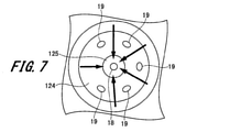
- FIG. 7 is a plan view of the sheet portion 124 of the injection hole forming member 12 as viewed from the inside.
- the sack chamber injection hole 18 is provided in the sack chamber 125, which is the center of the seat portion 124. Therefore, fuel flows into the sack chamber injection hole 18 from all directions of 360 ° of the seat portion 124. Therefore, the amount of fuel flowing into the seat injection hole 19 can be reduced, and excessive fuel flow into the seat injection hole 19 can be suppressed.
- the spray length of the sack chamber spray F1 at the initial stage of spraying is longer than that of the sheet portion spray F2. Further, as described above, the injection shaft Fa of the sack chamber injection hole 18 is directed to the ignition region 300a of the spark plug 300. Therefore, even if the spray length of the sheet portion spray F2 is shortened, the combustion stability at fast idle can be maintained or improved.
- the seat portion injection hole 19 is not arranged on the spark plug 300 side with respect to the sack chamber injection hole 18. Therefore, it is possible to prevent the fuel spray F2 from reaching the cylinder head, intake valve, exhaust valve, etc. of the internal combustion engine and adhering fuel to the cylinder head, intake valve, exhaust valve, and the like.
- Tip side sliding part 232 ... Valve body side seat surface, 233 ... Convex part , 300 ... spark plug, 300a ... ignition area, 301 ... cylinder, 302 ... piston, 310 ... combustion chamber, AX1 ... center axis, Da ... axis direction, F1 ... sack chamber spray, F2 ... sheet spray, S1 ... bubble, T1 ... Collapse energy
Abstract
A fuel injection device according to the present invention comprises a nozzle body, an injection hole formation member, and a valve body. The injection hole formation member has: a seat part having a seat surface; and a suction chamber that is a recess, the suction chamber being formed at a tip end section of the seat part and being recessed from the seat surface towards the tip-end-section side. Furthermore, a suction chamber injection hole through which fuel is injected towards a spark plug is formed in the suction chamber.
Description
本発明は、燃料噴射装置に関するものである。
The present invention relates to a fuel injection device.
従来、内燃機関として、燃料噴射装置によりシリンダ内に燃料を直接噴射する筒内噴射型の内燃機関が用いられている。従来の燃料噴射装置に関する技術としては、例えば、特許文献1に記載されているようなものがある。
Conventionally, as an internal combustion engine, an in-cylinder injection type internal combustion engine that directly injects fuel into a cylinder by a fuel injection device has been used. As a technique relating to a conventional fuel injection device, for example, there is one described in Patent Document 1.
特許文献1には、弁体と弁体の先端側において燃料を噴射する複数の噴射孔が形成された噴射孔形成部とを備えた燃料噴射装置に関する技術が記載されている。そして、特許文献1では、噴射孔形成部には、噴射孔形成部の中心軸線と第1噴射孔軸線との交差角度がθ1となる第1噴射孔と、噴射孔形成部の中心軸線と第2噴射孔軸線との交差角度がθ1よりも大きいθ2となる第2噴射孔と、が形成されることが記載されている。
Patent Document 1 describes a technique relating to a fuel injection device including a valve body and an injection hole forming portion in which a plurality of injection holes for injecting fuel are formed on the tip end side of the valve body. Further, in Patent Document 1, the injection hole forming portion includes a first injection hole in which the intersection angle between the central axis of the injection hole forming portion and the first injection hole axis is θ1, and the central axis and the first injection hole forming portion. It is described that a second injection hole having a crossing angle with the injection hole axis of θ2 larger than θ1 is formed.
また、噴射中または噴射後の燃料は、燃料噴射装置の先端部に付着しやすい。しかしながら、特許文献1に記載された技術では、先端部に付着した燃料について考慮されていなかった。その結果、特許文献1に記載された技術では、先端部に付着した燃料が煤となることで、輝炎が発生しやすくなり、排ガス性能が悪化する、という問題を有していた。
In addition, the fuel during or after injection tends to adhere to the tip of the fuel injection device. However, in the technique described in Patent Document 1, the fuel adhering to the tip portion is not considered. As a result, the technique described in Patent Document 1 has a problem that the fuel adhering to the tip portion becomes soot, which tends to generate a bright flame and deteriorates the exhaust gas performance.
本目的は、上記の問題点を考慮し、先端部の表面に燃料が付着することを抑制し、燃焼の安定性の向上を図ることができる燃料噴射装置を提供することにある。
The purpose of the present invention is to provide a fuel injection device capable of suppressing fuel from adhering to the surface of the tip portion and improving combustion stability in consideration of the above problems.
上記課題を解決し、目的を達成するため、燃料噴射装置は、ノズル本体と、噴射孔形成部材と、弁体と、を備えている。ノズル本体は、点火プラグが配置された内燃機関のシリンダに設置される。噴射孔形成部材は、ノズル本体の先端部に設けられる。弁体は、噴射孔形成部材に設けたシート面に接触及び離反する弁体側シート面が形成されている。
噴射孔形成部材は、シート面を有するシート部と、シート部における先端部に形成され、シート面から先端部側に向けて凹んだ凹部であるサック室と、を有している。そして、サック室には、燃料を点火プラグに向けて噴射するサック室噴射孔が形成されている。 In order to solve the above problems and achieve the object, the fuel injection device includes a nozzle body, an injection hole forming member, and a valve body. The nozzle body is installed in the cylinder of the internal combustion engine in which the spark plug is arranged. The injection hole forming member is provided at the tip of the nozzle body. The valve body is formed with a valve body side seat surface that comes into contact with and separates from the seat surface provided on the injection hole forming member.
The injection hole forming member has a seat portion having a seat surface and a sack chamber formed at the tip portion of the seat portion and recessed from the seat surface toward the tip portion side. The sack chamber is formed with a sack chamber injection hole for injecting fuel toward the spark plug.
上記構成の燃料噴射装置によれば、先端部の表面に燃料が付着することを抑制し、燃焼の安定性の向上を図ることができる。
According to the fuel injection device having the above configuration, it is possible to suppress the adhesion of fuel to the surface of the tip portion and improve the stability of combustion.
以下、燃料噴射装置の実施の形態例について、図1~図7を参照して説明する。なお、各図において共通の部材には、同一の符号を付している。
Hereinafter, an example of the embodiment of the fuel injection device will be described with reference to FIGS. 1 to 7. The common members in each figure are designated by the same reference numerals.
1.実施の形態例
1-1.燃料噴射装置の構成
まず、実施の形態例(以下、「本例」という。)にかかる燃料噴射装置の構成について図1を参照して説明する。
図1は、燃料噴射装置を示す分解斜視図である。 1. 1. Embodiment 1-1. Configuration of Fuel Injection Device First, the configuration of the fuel injection device according to the embodiment (hereinafter referred to as “this example”) will be described with reference to FIG.
FIG. 1 is an exploded perspective view showing a fuel injection device.
図1に示す燃料噴射装置は、内燃機関として、入行程、圧縮行程、燃焼(膨張)行程、排気行程の4行程を繰り返す4サイクルエンジンに用いられるものである。また、燃料噴射装置は、各気筒のシリンダの中に燃料を噴射する筒内噴射型の内燃機関に適用されるものである。
The fuel injection device shown in FIG. 1 is used as an internal combustion engine in a four-cycle engine that repeats four strokes of an entry stroke, a compression stroke, a combustion (expansion) stroke, and an exhaust stroke. Further, the fuel injection device is applied to an in-cylinder injection type internal combustion engine that injects fuel into the cylinders of each cylinder.
図1に示すように、燃料噴射装置1は、ノズル本体10と、弁体20と、可動コア30と、固定コア40と、コイル50と、ハウジング70と、接続部80と、フィルタ90と、を備えている。また、燃料噴射装置1は、第1ばね61と、第2ばね63と、調整部材62とを備えている。
As shown in FIG. 1, the fuel injection device 1 includes a nozzle body 10, a valve body 20, a movable core 30, a fixed core 40, a coil 50, a housing 70, a connection portion 80, a filter 90, and the like. It is equipped with. Further, the fuel injection device 1 includes a first spring 61, a second spring 63, and an adjusting member 62.
[ノズル本体]
ノズル本体10は、筒状に形成されている。ノズル本体10の中心軸線AX1に沿う軸線方向Da「以下、単に「軸線方向Da」という」の一端部である先端部には、第1内部空間130が形成されている。また、ノズル本体10の軸線方向Daの他端部である後端部には、先端部よりも外径が大きい大径部14が形成されている。この大径部14には、第2内部空間140が形成されている。第1内部空間130と第2内部空間140は、ノズル本体10の軸線方向Daに沿って形成された連通孔16によって連通している。 [Nozzle body]
Thenozzle body 10 is formed in a cylindrical shape. A first internal space 130 is formed at the tip end portion, which is one end of the axial direction Da "hereinafter, simply referred to as" axial direction Da "" along the central axis AX1 of the nozzle body 10. Further, a large diameter portion 14 having an outer diameter larger than that of the tip portion is formed at the rear end portion which is the other end portion of the nozzle body 10 in the axial direction Da. A second internal space 140 is formed in the large diameter portion 14. The first internal space 130 and the second internal space 140 are communicated with each other by a communication hole 16 formed along the axial direction Da of the nozzle body 10.
ノズル本体10は、筒状に形成されている。ノズル本体10の中心軸線AX1に沿う軸線方向Da「以下、単に「軸線方向Da」という」の一端部である先端部には、第1内部空間130が形成されている。また、ノズル本体10の軸線方向Daの他端部である後端部には、先端部よりも外径が大きい大径部14が形成されている。この大径部14には、第2内部空間140が形成されている。第1内部空間130と第2内部空間140は、ノズル本体10の軸線方向Daに沿って形成された連通孔16によって連通している。 [Nozzle body]
The
第1内部空間130は、ノズル本体10の先端部から軸線方向Daの内側に向けて凹んだ凹部である。この第1内部空間130には、噴射孔形成部材12が挿入又は圧入により取り付けられている。また、噴射孔形成部材12は、ノズル本体10における先端部の開口部の内周縁において全周に亘って溶接されることで、ノズル本体10に固定される。噴射孔形成部材12には、燃料を噴射する複数の噴射孔18、19が形成されている。なお、噴射孔形成部材12及び噴射孔18、19の詳細な構成については、後述する。
The first internal space 130 is a concave portion recessed from the tip end portion of the nozzle body 10 toward the inside of the axial direction Da. An injection hole forming member 12 is attached to the first internal space 130 by insertion or press fitting. Further, the injection hole forming member 12 is fixed to the nozzle body 10 by being welded over the entire circumference at the inner peripheral edge of the opening at the tip of the nozzle body 10. A plurality of injection holes 18 and 19 for injecting fuel are formed in the injection hole forming member 12. The detailed configuration of the injection hole forming member 12 and the injection holes 18 and 19 will be described later.
また、ノズル本体10における先端部側の外周面には、複数(本例では2つ)の溝131が形成されている。溝131は、ノズル本体10の外周面の周方向に沿って連続して形成されている。溝131には、シール部材15がはめ込まれている。シール部材15は、燃料噴射装置1が内燃機関のシリンダ301(図2参照)に取り付けられた際に、シリンダ301と燃料噴射装置1との隙間を密閉する。
Further, a plurality of (two in this example) grooves 131 are formed on the outer peripheral surface of the nozzle body 10 on the tip end side. The groove 131 is continuously formed along the circumferential direction of the outer peripheral surface of the nozzle body 10. A sealing member 15 is fitted in the groove 131. The seal member 15 seals the gap between the cylinder 301 and the fuel injection device 1 when the fuel injection device 1 is attached to the cylinder 301 (see FIG. 2) of the internal combustion engine.
第2内部空間140は、大径部14の後端側が開口し、軸線方向Daの先端側に向けて凹んだ有底の凹部である。第2内部空間140には、後述する可動コア30と、固定コア40の一部が配置される。第2内部空間140における底部の中央部には、第2内部空間140と同心円上に形成されたばね収容部141が形成されている。ばね収容部141は、第2内部空間140の底部から先端部に向けて円筒状に凹んだ凹部である。このばね収容部141には、第2ばね63の一端部が収容される。
The second internal space 140 is a bottomed recess in which the rear end side of the large diameter portion 14 is open and recessed toward the tip end side in the axial direction Da. In the second internal space 140, a movable core 30 described later and a part of the fixed core 40 are arranged. A spring accommodating portion 141 formed concentrically with the second internal space 140 is formed in the central portion of the bottom portion of the second internal space 140. The spring accommodating portion 141 is a concave portion recessed in a cylindrical shape from the bottom portion of the second internal space 140 toward the tip end portion. One end of the second spring 63 is accommodated in the spring accommodating portion 141.
[弁体]
このノズル本体10の内部には、弁体20が軸線方向Daに沿って移動可能に配置されている。弁体20は、円柱状に形成されている。弁体20は、後端部21と、先端部23と、後端部21と先端部23の中間を示す中間部22とを有している。先端部23は、弁体20の軸線方向Daの先端側に形成され、後端部21は、弁体20の軸線方向Daの後端側に形成されている。 [Valve body]
Inside thenozzle body 10, the valve body 20 is movably arranged along the axial direction Da. The valve body 20 is formed in a columnar shape. The valve body 20 has a rear end portion 21, a tip portion 23, and an intermediate portion 22 indicating an intermediate portion between the rear end portion 21 and the tip portion 23. The tip portion 23 is formed on the front end side of the valve body 20 in the axial direction Da, and the rear end portion 21 is formed on the rear end side of the valve body 20 in the axial direction Da.
このノズル本体10の内部には、弁体20が軸線方向Daに沿って移動可能に配置されている。弁体20は、円柱状に形成されている。弁体20は、後端部21と、先端部23と、後端部21と先端部23の中間を示す中間部22とを有している。先端部23は、弁体20の軸線方向Daの先端側に形成され、後端部21は、弁体20の軸線方向Daの後端側に形成されている。 [Valve body]
Inside the
先端部23は、ノズル本体10の先端部に設けた噴射孔形成部材12に収容されている。先端部23は、弁体20が軸線方向Daに沿って移動することで、噴射孔形成部材12に設けた噴射孔18、19を開閉する。なお、先端部23の詳細な構成については、後述する。
The tip portion 23 is housed in an injection hole forming member 12 provided at the tip portion of the nozzle body 10. The tip portion 23 opens and closes the injection holes 18 and 19 provided in the injection hole forming member 12 by the valve body 20 moving along the axial direction Da. The detailed configuration of the tip portion 23 will be described later.
中間部22は、先端部23における軸線方向Daの後端側から連続して設けられている。中間部22は、ノズル本体10の連通孔16に配置される。中間部22の外周面221と、連通孔16の内周面との間には、間隙G1が形成されている。中間部22における軸線方向Daの後端側からは、後端部21が連続して設けられている。
The intermediate portion 22 is continuously provided from the rear end side of the tip portion 23 in the axial direction Da. The intermediate portion 22 is arranged in the communication hole 16 of the nozzle body 10. A gap G1 is formed between the outer peripheral surface 221 of the intermediate portion 22 and the inner peripheral surface of the communication hole 16. The rear end portion 21 is continuously provided from the rear end side of the intermediate portion 22 in the axial direction Da.
後端部21は、ノズル本体10における第2内部空間140に配置される。後端部21は、中間部22の外径よりも大きな略円柱状に形成されている。後端部21は、後述する固定コア40の筒孔内に内挿される。後端部21には、後端側摺動部211と、複数の流路形成部212と、係合部213が設けられている。
The rear end portion 21 is arranged in the second internal space 140 in the nozzle body 10. The rear end portion 21 is formed in a substantially columnar shape larger than the outer diameter of the intermediate portion 22. The rear end portion 21 is inserted into the tubular hole of the fixed core 40 described later. The rear end portion 21 is provided with a rear end side sliding portion 211, a plurality of flow path forming portions 212, and an engaging portion 213.
後端側摺動部211は、後端部21における外周面に形成されている。後端側摺動部211は、後述する固定コア40の内周面41に摺動可能に支持される。これにより、弁体20は、固定コア40により軸線方向Daに沿って移動可能に支持される。
The rear end side sliding portion 211 is formed on the outer peripheral surface of the rear end portion 21. The rear end side sliding portion 211 is slidably supported on the inner peripheral surface 41 of the fixed core 40 described later. As a result, the valve body 20 is movably supported by the fixed core 40 along the axial direction Da.
複数の流路形成部212は、後端部21の外周面を軸線方向Daに沿って複数切り欠くことで形成されている。そして、流路形成部212は、後述する固定コア40の内周面41との間に燃料が通過する流路FCを形成する。
The plurality of flow path forming portions 212 are formed by notching a plurality of outer peripheral surfaces of the rear end portion 21 along the axial direction Da. Then, the flow path forming portion 212 forms a flow path FC through which fuel passes between the inner peripheral surface 41 of the fixed core 40 described later.
係合部213は、後端部21に設けた流路形成部212よりも軸線方向Daの先端部側に設けられている。そして、係合部213は、後端部21の外周面から径方向の外側に向けて張り出している。この係合部213は、弁体20の開閉弁動作時に後述する可動コア30と係合する。
The engaging portion 213 is provided on the tip end side in the axial direction Da with respect to the flow path forming portion 212 provided on the rear end portion 21. The engaging portion 213 projects radially outward from the outer peripheral surface of the rear end portion 21. The engaging portion 213 engages with the movable core 30, which will be described later, when the on-off valve of the valve body 20 operates.
また、後端部21における軸線方向Daの後端部側の端面には、第1ばね61の一端部が当接されている。弁体20は、第1ばね61により軸線方向Daの先端部側(閉弁側)に向けて付勢されている。
Further, one end of the first spring 61 is in contact with the end surface of the rear end 21 on the rear end side in the axial direction Da. The valve body 20 is urged by the first spring 61 toward the tip end side (valve closed side) in the axial direction Da.
上述した構成を有する弁体20は、SUS等の金属材料等で形成されている。
The valve body 20 having the above-mentioned structure is made of a metal material such as SUS.
[可動コア]
次に、可動コア30について説明する。可動コア30は、ノズル本体10の第2内部空間140において、弁体20の後端部21と第2内部空間140の底部との間に配置されている。また、可動コア30の外周面と第2内部空間の内周面との間には、微小な間隙G3が形成されている。そのため、可動コア30は、第2内部空間140内において軸線方向Daに沿って移動可能に配置される。 [Movable core]
Next, themovable core 30 will be described. The movable core 30 is arranged in the second internal space 140 of the nozzle body 10 between the rear end portion 21 of the valve body 20 and the bottom portion of the second internal space 140. Further, a minute gap G3 is formed between the outer peripheral surface of the movable core 30 and the inner peripheral surface of the second internal space. Therefore, the movable core 30 is movably arranged along the axial direction Da in the second internal space 140.
次に、可動コア30について説明する。可動コア30は、ノズル本体10の第2内部空間140において、弁体20の後端部21と第2内部空間140の底部との間に配置されている。また、可動コア30の外周面と第2内部空間の内周面との間には、微小な間隙G3が形成されている。そのため、可動コア30は、第2内部空間140内において軸線方向Daに沿って移動可能に配置される。 [Movable core]
Next, the
可動コア30は、円筒状に形成されている。可動コア30には、挿通孔31と、偏心貫通孔32が形成されている。挿通孔31及び偏心貫通孔32は、可動コア30における軸線方向Daの一端部から他端部にかけて貫通する貫通孔である。挿通孔31は、可動コア30の中心軸上に形成されている。そして、挿通孔31には、弁体20の中間部22が挿通している。
The movable core 30 is formed in a cylindrical shape. The movable core 30 is formed with an insertion hole 31 and an eccentric through hole 32. The insertion hole 31 and the eccentric through hole 32 are through holes that penetrate from one end to the other end of the axial direction Da in the movable core 30. The insertion hole 31 is formed on the central axis of the movable core 30. The intermediate portion 22 of the valve body 20 is inserted into the insertion hole 31.
偏心貫通孔32は、可動コア30の中心軸から偏心した位置に形成されている。偏心貫通孔32は、流路形成部212と固定コア40の内周面41によって形成された流路FCに連通している。そして、偏心貫通孔32は、燃料が通過する流路FCを形成する。
The eccentric through hole 32 is formed at a position eccentric from the central axis of the movable core 30. The eccentric through hole 32 communicates with the flow path FC formed by the flow path forming portion 212 and the inner peripheral surface 41 of the fixed core 40. The eccentric through hole 32 forms a flow path FC through which the fuel passes.
可動コア30における軸線方向Daの先端側の端面には、第2ばね63の他端部が当接している。そのため、第2ばね63は、可動コア30とノズル本体10のばね収容部141の間に介在される。また、可動コア30における軸線方向Daの後端側の端面には、固定コア40が当接している。
The other end of the second spring 63 is in contact with the end surface of the movable core 30 on the tip end side in the axial direction Da. Therefore, the second spring 63 is interposed between the movable core 30 and the spring accommodating portion 141 of the nozzle body 10. Further, the fixed core 40 is in contact with the end surface of the movable core 30 on the rear end side in the axial direction Da.
[固定コア]
次に、固定コア40は、可動コア30を磁気吸引力によって吸引する部材である。固定コア40は、外周面に凹凸を有する略円筒状に形成されている。固定コア40における軸線方向Daの先端部は、ノズル本体10の大径部14の内側、すなわち第2内部空間140内に圧入されている。そして、ノズル本体10と固定コア40は、溶接により接合される。れにより、ノズル本体10と固定コア40との間の隙間が密閉され、ノズル本体10の内部の空間が密閉される。 [Fixed core]
Next, the fixedcore 40 is a member that attracts the movable core 30 by magnetic attraction. The fixed core 40 is formed in a substantially cylindrical shape having irregularities on the outer peripheral surface. The tip of the axial Da in the fixed core 40 is press-fitted into the inside of the large diameter portion 14 of the nozzle body 10, that is, into the second internal space 140. Then, the nozzle body 10 and the fixed core 40 are joined by welding. As a result, the gap between the nozzle body 10 and the fixed core 40 is sealed, and the space inside the nozzle body 10 is sealed.
次に、固定コア40は、可動コア30を磁気吸引力によって吸引する部材である。固定コア40は、外周面に凹凸を有する略円筒状に形成されている。固定コア40における軸線方向Daの先端部は、ノズル本体10の大径部14の内側、すなわち第2内部空間140内に圧入されている。そして、ノズル本体10と固定コア40は、溶接により接合される。れにより、ノズル本体10と固定コア40との間の隙間が密閉され、ノズル本体10の内部の空間が密閉される。 [Fixed core]
Next, the fixed
また、固定コア40の先端部は、第2内部空間140に配置された可動コア30における軸線方向Daの後端側の端面と対向する。固定コア40における可動コア30の対向する先端部を、硬質クロムメッキや無電解ニッケルメッキ等のメッキによって被覆してもよい。これにより、可動コア30が衝突する固定コア40の先端部の耐久性及び信頼性を向上させることができる。
Further, the tip end portion of the fixed core 40 faces the end surface on the rear end side of the axial direction Da in the movable core 30 arranged in the second internal space 140. The opposite tip portions of the movable core 30 in the fixed core 40 may be coated with plating such as hard chrome plating or electroless nickel plating. This makes it possible to improve the durability and reliability of the tip portion of the fixed core 40 with which the movable core 30 collides.
同様に、可動コア30における固定コア40と対向する後端部を、硬質クロムメッキや無電解ニッケルメッキ等のメッキによって被覆してもよい。これにより、可動コア30として比較的柔らかい軟磁性ステンレス鋼を適用した場合でも、可動コア30の耐久性及び信頼性を確保することができる。
Similarly, the rear end portion of the movable core 30 facing the fixed core 40 may be coated with plating such as hard chrome plating or electroless nickel plating. Thereby, even when a relatively soft soft magnetic stainless steel is applied as the movable core 30, the durability and reliability of the movable core 30 can be ensured.
なお、固定コア40における軸線方向Daの後端部側は、ノズル本体10の第2内部空間140から軸線方向Daの後端に向けて突出している。
The rear end side of the axial Da in the fixed core 40 protrudes from the second internal space 140 of the nozzle body 10 toward the rear end of the axial Da.
固定コア40には、貫通孔42が形成されている。貫通孔42は、中心軸線AX1と同軸上に形成されている。そして、貫通孔42は、燃料が通過する流路FCを形成する。また、固定コア40における軸線方向Daの後端部には、貫通孔42に連通する開口部43が形成されている。この開口部43から貫通孔42に向けて燃料が導入される。また、開口部43から貫通孔42にかけてフィルタ90が挿入されている。
A through hole 42 is formed in the fixed core 40. The through hole 42 is formed coaxially with the central axis AX1. Then, the through hole 42 forms a flow path FC through which the fuel passes. Further, an opening 43 communicating with the through hole 42 is formed at the rear end portion of the fixed core 40 in the axial direction Da. Fuel is introduced from the opening 43 toward the through hole 42. Further, the filter 90 is inserted from the opening 43 to the through hole 42.
さらに、貫通孔42における軸線方向Daの先端部側には、第1ばね61及び調整部材62が配置されている。第1ばね61は、調整部材62よりも貫通孔42の先端部側に配置されている。調整部材62は、貫通孔42に圧入されて、固定コア40の内部に固定されている。また、貫通孔42の先端部からが、弁体20の後端部21が挿入される。第1ばね61は、調整部材62と弁体20の後端部21の間に介在される。そして、第1ばね61は、弁体20をノズル本体10の先端部に向けて軸線方向Daに付勢している。
Further, the first spring 61 and the adjusting member 62 are arranged on the tip end side of the axial direction Da in the through hole 42. The first spring 61 is arranged on the tip end side of the through hole 42 with respect to the adjusting member 62. The adjusting member 62 is press-fitted into the through hole 42 and fixed inside the fixed core 40. Further, the rear end portion 21 of the valve body 20 is inserted from the tip end portion of the through hole 42. The first spring 61 is interposed between the adjusting member 62 and the rear end portion 21 of the valve body 20. Then, the first spring 61 urges the valve body 20 toward the tip of the nozzle body 10 in the axial direction Da.
また、調整部材62における固定コア40に対する固定位置を調整することで、第1ばね61における弁体20の付勢力を調整することができる。これにより、弁体20の先端部23がノズル本体10の後述する噴射孔形成部材12に設けたシート面124aに押し付ける初期荷重を調整することができる。
Further, by adjusting the fixed position of the adjusting member 62 with respect to the fixed core 40, the urging force of the valve body 20 in the first spring 61 can be adjusted. Thereby, the initial load that the tip portion 23 of the valve body 20 presses against the seat surface 124a provided on the injection hole forming member 12 described later of the nozzle body 10 can be adjusted.
ここで、第1ばね61が弁体20をノズル本体10の先端部に向けて付勢する付勢力は、第2ばね63が可動コア30を固定コア40に向けて付勢する付勢力よりも大きく設定されている。
Here, the urging force by which the first spring 61 urges the valve body 20 toward the tip of the nozzle body 10 is larger than the urging force by which the second spring 63 urges the movable core 30 toward the fixed core 40. It is set large.
[コイル]
次に、コイル50について説明する。コイル50は、円筒状のコイルボビン51に巻回されている。そして、コイル50は、コイルボビン51に巻回されて、ノズル本体10における大径部14の外周面の一部及び固定コア40の先端部の外周面の一部を覆うようにして配置される。コイル50の巻き始めと巻き終わりの端部は、不図示の配線を介して後述する接続部80のコネクタ81の電力供給用の端子811に接続されている。コイル50及びコイルボビン51の外周には、ハウジング70が固定されている。 [coil]
Next, thecoil 50 will be described. The coil 50 is wound around a cylindrical coil bobbin 51. The coil 50 is wound around the coil bobbin 51 and is arranged so as to cover a part of the outer peripheral surface of the large diameter portion 14 of the nozzle body 10 and a part of the outer peripheral surface of the tip end portion of the fixed core 40. The winding start and winding end ends of the coil 50 are connected to the power supply terminal 811 of the connector 81 of the connection portion 80, which will be described later, via wiring (not shown). A housing 70 is fixed to the outer periphery of the coil 50 and the coil bobbin 51.
次に、コイル50について説明する。コイル50は、円筒状のコイルボビン51に巻回されている。そして、コイル50は、コイルボビン51に巻回されて、ノズル本体10における大径部14の外周面の一部及び固定コア40の先端部の外周面の一部を覆うようにして配置される。コイル50の巻き始めと巻き終わりの端部は、不図示の配線を介して後述する接続部80のコネクタ81の電力供給用の端子811に接続されている。コイル50及びコイルボビン51の外周には、ハウジング70が固定されている。 [coil]
Next, the
[ハウジング]
ハウジング70は、有底の円筒状に形成されている。ハウジング70における軸線方向Daの先端部である底部には、貫通孔71が形成されている。貫通孔71は、底部の中央部に形成されている。この貫通孔71には、ノズル本体10の大径部14が挿入される。そして、貫通孔71の開口縁とノズル本体10の外周面との間は、例えば、全周にわたって溶接されている。これにより、ノズル本体10は、ハウジング70に固定される。 [housing]
Thehousing 70 is formed in a bottomed cylindrical shape. A through hole 71 is formed in the bottom portion of the housing 70, which is the tip end portion in the axial direction Da. The through hole 71 is formed in the central portion of the bottom portion. The large diameter portion 14 of the nozzle body 10 is inserted into the through hole 71. Then, for example, the opening edge of the through hole 71 and the outer peripheral surface of the nozzle body 10 are welded over the entire circumference. As a result, the nozzle body 10 is fixed to the housing 70.
ハウジング70は、有底の円筒状に形成されている。ハウジング70における軸線方向Daの先端部である底部には、貫通孔71が形成されている。貫通孔71は、底部の中央部に形成されている。この貫通孔71には、ノズル本体10の大径部14が挿入される。そして、貫通孔71の開口縁とノズル本体10の外周面との間は、例えば、全周にわたって溶接されている。これにより、ノズル本体10は、ハウジング70に固定される。 [housing]
The
また、ハウジング70は、固定コア40の先端部側、コイルボビン51及びコイル50の外周を囲むようにして配置される。そして、ハウジング70の内周面は、ノズル本体10の大径部14及びコイル50と対向し、外周ヨーク部を形成する。このように、コイル50の周りには、固定コア40、可動コア30、ノズル本体10及びハウジング70を含むトロダイル状の磁気通路が形成されている。
Further, the housing 70 is arranged so as to surround the tip end side of the fixed core 40, the coil bobbin 51, and the outer periphery of the coil 50. The inner peripheral surface of the housing 70 faces the large diameter portion 14 of the nozzle body 10 and the coil 50, and forms an outer peripheral yoke portion. As described above, a trodile-shaped magnetic passage including the fixed core 40, the movable core 30, the nozzle body 10 and the housing 70 is formed around the coil 50.
[接続部]
接続部80は、樹脂により形成されている。そして、接続部80は、固定コア40、コイル50、コイルボビン51及びハウジング70との間に充填される。また、接続部80は、ハウジング70よりも軸線方向Daの後端側において、固定コア40の後端部を除く外周面を覆う。そして、接続部80は、電力供給用の端子811を有するコネクタ81を形成するようにモールド成形されている。端子811は、不図示のプラグの接続端子に接続される。これにより、燃料噴射装置1は、高電圧電源又はバッテリ電源に接続される。そして、不図示のエンジンコントロールユニット(ECU)によってコイル50に対する通電が制御される。 [Connection part]
The connectingportion 80 is made of resin. The connection portion 80 is filled between the fixed core 40, the coil 50, the coil bobbin 51, and the housing 70. Further, the connecting portion 80 covers the outer peripheral surface of the fixed core 40 on the rear end side in the axial direction Da with respect to the housing 70, excluding the rear end portion. The connection portion 80 is molded so as to form a connector 81 having a terminal 811 for power supply. The terminal 811 is connected to a connection terminal of a plug (not shown). As a result, the fuel injection device 1 is connected to the high voltage power supply or the battery power supply. Then, the energization of the coil 50 is controlled by an engine control unit (ECU) (not shown).
接続部80は、樹脂により形成されている。そして、接続部80は、固定コア40、コイル50、コイルボビン51及びハウジング70との間に充填される。また、接続部80は、ハウジング70よりも軸線方向Daの後端側において、固定コア40の後端部を除く外周面を覆う。そして、接続部80は、電力供給用の端子811を有するコネクタ81を形成するようにモールド成形されている。端子811は、不図示のプラグの接続端子に接続される。これにより、燃料噴射装置1は、高電圧電源又はバッテリ電源に接続される。そして、不図示のエンジンコントロールユニット(ECU)によってコイル50に対する通電が制御される。 [Connection part]
The connecting
1-2.燃料噴射装置の動作例
次に、上述した構成を有する燃料噴射装置1の動作例について図1及び図2を参照して説明する。
図2は、燃料噴射装置1を内燃機関に搭載した状態を示す模式図である。 1-2. Operation Example of Fuel Injection Device Next, an operation example of thefuel injection device 1 having the above-described configuration will be described with reference to FIGS. 1 and 2.
FIG. 2 is a schematic view showing a state in which thefuel injection device 1 is mounted on the internal combustion engine.
次に、上述した構成を有する燃料噴射装置1の動作例について図1及び図2を参照して説明する。
図2は、燃料噴射装置1を内燃機関に搭載した状態を示す模式図である。 1-2. Operation Example of Fuel Injection Device Next, an operation example of the
FIG. 2 is a schematic view showing a state in which the
図2に示すように、燃料噴射装置1は、内燃機関を構成するシリンダ301の壁面に設置される。そして、燃料噴射装置1は、燃料を噴射する先端部であるノズル本体10の先端部が、シリンダ301の内壁面とピストン302で形成される燃焼室310内に配置される。また、燃料噴射装置1におけるノズル本体10の先端部は、点火プラグ300に向けて配置される。
As shown in FIG. 2, the fuel injection device 1 is installed on the wall surface of the cylinder 301 constituting the internal combustion engine. Then, in the fuel injection device 1, the tip of the nozzle body 10, which is the tip for injecting fuel, is arranged in the combustion chamber 310 formed by the inner wall surface of the cylinder 301 and the piston 302. Further, the tip of the nozzle body 10 in the fuel injection device 1 is arranged toward the spark plug 300.
上述したように、第1ばね61の付勢力は、第2ばね63の付勢力よりも大きく設定されている。そのため、後述するコイル50が通電されていない状態では、弁体20の先端部23は、後述する噴射孔形成部材12のシート面124aに押し付けられる。その結果、噴射孔18、19に至る流路FCは、弁体20に閉じられて閉弁状態となる。
As described above, the urging force of the first spring 61 is set to be larger than the urging force of the second spring 63. Therefore, when the coil 50 described later is not energized, the tip portion 23 of the valve body 20 is pressed against the seat surface 124a of the injection hole forming member 12 described later. As a result, the flow path FC leading to the injection holes 18 and 19 is closed by the valve body 20 and is in a closed state.
次に、ECUによってコイル50に通電されると、固定コア40、可動コア30、ノズル本体10及びハウジング70を含む磁気回路に磁束が流れる。そして、固定コア40には、可動コア30を吸引する磁気吸引力が発生する。固定コア40の磁気吸引力が、第1ばね61の付勢力、すなわち設定荷重を超えると、可動コア30は、固定コア40へ向けて移動する。可動コア30は、固定コア40と対向する端面、すなわち後端側端面が固定コア40の先端側端面に衝突するまで移動する。
Next, when the coil 50 is energized by the ECU, magnetic flux flows in the magnetic circuit including the fixed core 40, the movable core 30, the nozzle body 10, and the housing 70. Then, a magnetic attraction force that attracts the movable core 30 is generated in the fixed core 40. When the magnetic attraction force of the fixed core 40 exceeds the urging force of the first spring 61, that is, the set load, the movable core 30 moves toward the fixed core 40. The movable core 30 moves until the end face facing the fixed core 40, that is, the rear end side end face collides with the front end side end face of the fixed core 40.
可動コア30が移動する際に、弁体20の後端部21に設けた係合部213と可動コア30が係合する。そのため、弁体20は、可動コア30と共に固定コア40に向けて軸線方向Daに沿って後端側に向けて移動する。
When the movable core 30 moves, the engaging portion 213 provided at the rear end portion 21 of the valve body 20 and the movable core 30 engage with each other. Therefore, the valve body 20 moves toward the rear end side along the axial direction Da toward the fixed core 40 together with the movable core 30.
弁体20が固定コア40へ向けて移動することで、弁体20の先端部23が噴射孔形成部材12から離反する。そのため、弁体20と噴射孔形成部材12との間に形成された噴射孔18に至るまでの流路FCが開通し、噴射孔18、19が開いた開弁状態となる。
As the valve body 20 moves toward the fixed core 40, the tip portion 23 of the valve body 20 separates from the injection hole forming member 12. Therefore, the flow path FC up to the injection hole 18 formed between the valve body 20 and the injection hole forming member 12 is opened, and the injection holes 18 and 19 are opened.
弁体20が開弁位置(開弁状態)にあるとき、フィルタ90を介して、燃料が固定コア40の開口部43に導入される。そして、燃料は、固定コア40の貫通孔42を通ってノズル本体10に向けて流れる。また、燃料は、貫通孔42に配置された調整部材62及び第1ばね61を通過し、弁体20の流路形成部212と固定コア40の内周面41との間に形成された流路FCを流れる。そして、燃料は、可動コア30の偏心貫通孔32を介して、ノズル本体10の第2内部空間140に流入する。
When the valve body 20 is in the valve open position (valve open state), fuel is introduced into the opening 43 of the fixed core 40 via the filter 90. Then, the fuel flows toward the nozzle body 10 through the through hole 42 of the fixed core 40. Further, the fuel passes through the adjusting member 62 and the first spring 61 arranged in the through hole 42, and the flow is formed between the flow path forming portion 212 of the valve body 20 and the inner peripheral surface 41 of the fixed core 40. It flows on the road FC. Then, the fuel flows into the second internal space 140 of the nozzle body 10 through the eccentric through hole 32 of the movable core 30.
第2内部空間140に流入した燃料は、弁体20とノズル本体10の連通孔16との間に形成された間隙G1を通過し、ノズル本体10の第1内部空間130に流れる。そして、燃料は、弁体20の先端部23と噴射孔形成部材12との間に形成された流路FCを流れて、噴射孔18、19を介して燃焼室310内へ噴射される。
The fuel that has flowed into the second internal space 140 passes through the gap G1 formed between the valve body 20 and the communication hole 16 of the nozzle body 10, and flows into the first internal space 130 of the nozzle body 10. Then, the fuel flows through the flow path FC formed between the tip portion 23 of the valve body 20 and the injection hole forming member 12, and is injected into the combustion chamber 310 through the injection holes 18 and 19.
また、ECUによってコイル50の通電が中断されると、固定コア40、可動コア30、ノズル本体10及びハウジング70を含む磁気回路を流れる磁束が消滅する。そして、可動コア30を吸引する固定コア40の磁気吸引力も消滅する。そのため、第1ばね61における弁体20をノズル本体10の噴射孔形成部材12に向けて付勢する弾性力が、第2ばね63における可動コア30を固定コア40に向けて付勢する弾性力よりも大きい初期状態に戻る。
Further, when the energization of the coil 50 is interrupted by the ECU, the magnetic flux flowing through the magnetic circuit including the fixed core 40, the movable core 30, the nozzle body 10 and the housing 70 disappears. Then, the magnetic attraction force of the fixed core 40 that attracts the movable core 30 also disappears. Therefore, the elastic force that urges the valve body 20 in the first spring 61 toward the injection hole forming member 12 of the nozzle body 10 and the elastic force that urges the movable core 30 in the second spring 63 toward the fixed core 40. Returns to a larger initial state.
これにより、弁体20は、第1ばね61によってノズル本体10の噴射孔形成部材12に向けて付勢されて、軸線方向Daに沿って先端部へ移動する。また、弁体20の係合部213と係合する可動コア30は、弁体20と共に軸線方向Daに沿って先端側に向けて移動する。これにより、弁体20の先端部23が後述する噴射孔形成部材12のシート面124aに押し付けられ、噴射孔18、19に至る流路FCは、弁体20に閉じられて閉弁状態となる。その結果、燃料噴射装置1による燃料の噴射が停止される。
As a result, the valve body 20 is urged toward the injection hole forming member 12 of the nozzle body 10 by the first spring 61, and moves to the tip portion along the axial direction Da. Further, the movable core 30 that engages with the engaging portion 213 of the valve body 20 moves toward the tip end side along the axial direction Da together with the valve body 20. As a result, the tip portion 23 of the valve body 20 is pressed against the seat surface 124a of the injection hole forming member 12, which will be described later, and the flow path FC leading to the injection holes 18 and 19 is closed by the valve body 20 and becomes a valve closed state. .. As a result, the injection of fuel by the fuel injection device 1 is stopped.
2.噴射孔、噴射孔形成部材、及び弁体の先端部の詳細な構成
次に、噴射孔18、19、噴射孔形成部材12及び弁体20の先端部23の詳細な構成について図1、図3及び図4を参照して説明する。
図3は、燃料噴射装置1の先端部を拡大して示す断面図、図4は、燃料噴射装置1の先端部を示す正面図である。 2. 2. Detailed Configuration of Injection Hole, Injection Hole Forming Member, and Tip of Valve Body Next, FIGS. 1 and 3 describe the detailed configuration of injection holes 18, 19, the injectionhole forming member 12, and the tip 23 of the valve body 20. And FIG. 4 will be described.
FIG. 3 is an enlarged cross-sectional view showing the tip of thefuel injection device 1, and FIG. 4 is a front view showing the tip of the fuel injection device 1.
次に、噴射孔18、19、噴射孔形成部材12及び弁体20の先端部23の詳細な構成について図1、図3及び図4を参照して説明する。
図3は、燃料噴射装置1の先端部を拡大して示す断面図、図4は、燃料噴射装置1の先端部を示す正面図である。 2. 2. Detailed Configuration of Injection Hole, Injection Hole Forming Member, and Tip of Valve Body Next, FIGS. 1 and 3 describe the detailed configuration of injection holes 18, 19, the injection
FIG. 3 is an enlarged cross-sectional view showing the tip of the
図1、図3に示すように、噴射孔形成部材12は、ノズル本体10の第1内部空間130の内壁面に圧入される筒部122と、筒部122の軸線方向Daの先端部側から連続するシート部124とを有している。
As shown in FIGS. 1 and 3, the injection hole forming member 12 is pressed into the inner wall surface of the first internal space 130 of the nozzle body 10 from the tubular portion 122 and the tip end side of the tubular portion 122 in the axial direction Da. It has a continuous sheet portion 124.
筒部122の内周面121には、弁体20の先端部23に設けた先端側摺動部231が摺動する。また、筒部122には、複数の切り欠き部123が形成されている。複数の切り欠き部123は、筒部122の内周面121の周方向に等間隔に形成されている。そして、切り欠き部123と先端側摺動部231との間には、燃料が通過する流路FCが形成される。そして、流路FCは、シート部124に向けて延在している。
The tip side sliding portion 231 provided at the tip portion 23 of the valve body 20 slides on the inner peripheral surface 121 of the cylinder portion 122. Further, a plurality of notched portions 123 are formed in the tubular portion 122. The plurality of cutout portions 123 are formed at equal intervals in the circumferential direction of the inner peripheral surface 121 of the tubular portion 122. Then, a flow path FC through which the fuel passes is formed between the notch portion 123 and the tip side sliding portion 231. The flow path FC extends toward the seat portion 124.
シート部124は、筒部122における軸線方向Daの先端部側の開口を塞ぐようにして筒部122に連続して形成されている。シート部124は、軸線方向Daの先端側に向けて突出する略半球状の凹部である。シート部124における内部には、後述する弁体20の球面部230が接触及び離反するシート面124aが形成されている。シート面124aは、軸線方向Daの先端側に向かうに従い縮径する円錐台形状に形成されている。
The seat portion 124 is continuously formed in the tubular portion 122 so as to close the opening on the tip end side of the axial direction Da in the tubular portion 122. The seat portion 124 is a substantially hemispherical recess that protrudes toward the tip end side in the axial direction Da. Inside the seat portion 124, a seat surface 124a with which the spherical surface portion 230 of the valve body 20, which will be described later, comes into contact with and separates from each other is formed. The seat surface 124a is formed in a truncated cone shape whose diameter decreases toward the tip end side in the axial direction Da.
また、シート部124における軸線方向Daの先端部には、サック室125が形成されている。サック室125は、シート面124aにおける軸線方向Daの先端部に形成され、シート面124aからさらに軸線方向Daの先端部側に向けて略半球状凹んだ凹部である。また、サック室125は、燃料噴射装置1の中心軸線AX1上に形成されている。このサック室125には、後述する弁体20における球面部230の凸部233の少なくとも一部が挿入される。
Further, a sack chamber 125 is formed at the tip of the seat portion 124 in the axial direction Da. The sack chamber 125 is a concave portion formed at the tip end portion of the seat surface 124a in the axial direction Da, and is substantially hemispherically recessed from the seat surface 124a toward the tip end portion side in the axial direction Da. Further, the sack chamber 125 is formed on the central axis AX1 of the fuel injection device 1. At least a part of the convex portion 233 of the spherical portion 230 in the valve body 20, which will be described later, is inserted into the sack chamber 125.
弁体20の先端部23は、球面部230と、先端側摺動部231とを有している。先端側摺動部231は、噴射孔形成部材12における筒部122の内周面121を摺動する。先端側摺動部231よりも軸線方向Daの先端部側には、球面部230が連続して形成されている。
The tip portion 23 of the valve body 20 has a spherical surface portion 230 and a tip side sliding portion 231. The tip side sliding portion 231 slides on the inner peripheral surface 121 of the tubular portion 122 of the injection hole forming member 12. A spherical surface portion 230 is continuously formed on the tip end portion side in the axial direction Da with respect to the tip end side sliding portion 231.
球面部230は、略半球状に形成されている。球面部230は、弁体側シート面232と、凸部233とを有している。弁体側シート面232は、シート部124のシート面124aに対向し、シート面124aに対して接近及び離反する。そして、弁体側シート面232がシート面124aに接触した際に、後述する噴射孔18、19に至る流路FCが閉じられる。また、弁体側シート面232がシート面124aから離反すると、弁体側シート面232とシート面124aとの間に燃料が通過する流路FCが形成され、後述する噴射孔18、19から燃料が噴射される。弁体側シート面232とシート面124aが接触した際に、凸部233の一部は、サック室125に挿入に挿入される。
The spherical surface portion 230 is formed in a substantially hemispherical shape. The spherical surface portion 230 has a valve body side seat surface 232 and a convex portion 233. The valve body side seat surface 232 faces the seat surface 124a of the seat portion 124, and approaches and separates from the seat surface 124a. Then, when the valve body side seat surface 232 comes into contact with the seat surface 124a, the flow path FC leading to the injection holes 18 and 19 described later is closed. Further, when the valve body side seat surface 232 separates from the seat surface 124a, a flow path FC through which fuel passes is formed between the valve body side seat surface 232 and the seat surface 124a, and fuel is injected from the injection holes 18 and 19 described later. Will be done. When the valve body side seat surface 232 and the seat surface 124a come into contact with each other, a part of the convex portion 233 is inserted into the sack chamber 125 for insertion.
また、サック室125には、サック室噴射孔18が形成されており、シート面124aには、複数(本例では、5つ)のシート部噴射孔19が形成されている。
Further, the sack chamber 125 is formed with the sack chamber injection holes 18, and the seat surface 124a is formed with a plurality of (five in this example) seat portion injection holes 19.
サック室噴射孔18は、噴霧を形成するオリフィス孔18aと、平面形成用のザグリ穴18bの2段形状に形成されている。オリフィス孔18aは、サック室125の内壁面から外周面120に向けて延在している。
The sack chamber injection hole 18 is formed in a two-stage shape of an orifice hole 18a for forming a spray and a counterbore hole 18b for forming a flat surface. The orifice hole 18a extends from the inner wall surface of the sack chamber 125 toward the outer peripheral surface 120.
また、図2及び図3に示すように、サック室噴射孔18における燃料を噴射する方向であるオリフィス孔18aの軸方向(以下、「噴射軸」という)Faは、点火プラグ300を向いている。より詳細には、サック室噴射孔18の噴射軸Faは、点火プラグ300において火花が発生する点火領域300aに向けられている。そのため、サック室噴射孔18から噴射される(以下、「サック室噴霧」という)噴霧F1は、点火領域300aに向かう。
Further, as shown in FIGS. 2 and 3, the axial direction (hereinafter referred to as “injection shaft”) Fa of the orifice hole 18a, which is the direction in which fuel is injected in the sack chamber injection hole 18, faces the spark plug 300. .. More specifically, the injection shaft Fa of the sack chamber injection hole 18 is directed to the ignition region 300a where sparks are generated in the spark plug 300. Therefore, the spray F1 jetted from the sack chamber injection hole 18 (hereinafter referred to as “sack chamber spray”) heads toward the ignition region 300a.
ザグリ穴18bは、外周面120からオリフィス孔18aに向けて凹んだ凹部であり、オリフィス孔18aの周囲を囲むようにして形成される。ザグリ穴18bの開口径は、オリフィス孔18aの開口径よりも大きく設定されている。また、ザグリ穴18bにおける外周面120からオリフィス孔18aまでの長さは、オリフィス孔18aにおけるサック室125の内壁面からザグリ穴18bまでの長さよりも短く設定される。
The counterbore hole 18b is a recess recessed from the outer peripheral surface 120 toward the orifice hole 18a, and is formed so as to surround the periphery of the orifice hole 18a. The opening diameter of the counterbore hole 18b is set to be larger than the opening diameter of the orifice hole 18a. Further, the length from the outer peripheral surface 120 of the counterbore hole 18b to the orifice hole 18a is set shorter than the length from the inner wall surface of the sack chamber 125 in the orifice hole 18a to the counterbore hole 18b.
シート部噴射孔19は、噴霧を形成するオリフィス孔19aと、ザグリ穴19bと、平面形成用の面押し穴19cの3段形状に形成されている。オリフィス孔19aは、シート面124aから外周面120に向けて延在している。ザグリ穴19bは、オリフィス孔19aを囲むようにして形成されており、オリフィス孔19aにおける外周面120側の端部から外周面120に向けて延在している。また、面押し穴19cは、外周面120からザグリ穴19bに向けて凹んだ凹部であり、ザグリ穴19bの周囲を囲むようにして形成されている。
The sheet portion injection hole 19 is formed in a three-stage shape of an orifice hole 19a for forming a spray, a counterbore hole 19b, and a surface push hole 19c for forming a flat surface. The orifice hole 19a extends from the seat surface 124a toward the outer peripheral surface 120. The counterbore hole 19b is formed so as to surround the orifice hole 19a, and extends from the end portion of the orifice hole 19a on the outer peripheral surface 120 side toward the outer peripheral surface 120. Further, the surface push hole 19c is a recess recessed from the outer peripheral surface 120 toward the counterbore hole 19b, and is formed so as to surround the periphery of the counterbore hole 19b.
なお、シート部噴射孔19は、噴射孔形成部材12における曲面部に形成されている。そのため、シート部噴射孔19には、オリフィス孔19aの長さを調整するために、ザグリ穴19bを設けている。これに対して、サック室噴射孔18は、噴射孔形成部材12における先端部に形成されている。そのため、シート部124におけるサック室125での厚さを調整することで、サック室噴射孔18におけるオリフィス孔18aの長さを容易に調整することができる。
The sheet portion injection hole 19 is formed on the curved surface portion of the injection hole forming member 12. Therefore, the sheet portion injection hole 19 is provided with a counterbore hole 19b in order to adjust the length of the orifice hole 19a. On the other hand, the sack chamber injection hole 18 is formed at the tip end portion of the injection hole forming member 12. Therefore, by adjusting the thickness of the seat portion 124 in the sack chamber 125, the length of the orifice hole 18a in the sack chamber injection hole 18 can be easily adjusted.
これにより、サック室噴射孔18では、オリフィス孔18aの長さの調整用の穴を設ける必要がなくなる。その結果、サック室噴射孔18を形成するための加工時間を削減することができる。
This eliminates the need to provide a hole for adjusting the length of the orifice hole 18a in the sack chamber injection hole 18. As a result, the processing time for forming the sack chamber injection hole 18 can be reduced.
さらに、ザグリ穴18bは、平面を形成できればよいため、その長さを最小化することができる。その結果、サック室噴射孔18から噴射された噴霧F1がザグリ穴18bの壁面に付着することを抑制することができる。
Further, since the counterbore hole 18b only needs to be able to form a flat surface, its length can be minimized. As a result, it is possible to prevent the spray F1 sprayed from the sack chamber injection hole 18 from adhering to the wall surface of the counterbore hole 18b.
なお、本例では、サック室噴射孔18を2段形状とし、シート部噴射孔19を3段形状とした例を説明したが、サック室噴射孔18及びシート部噴射孔19の段数は、これに限定されるものではない。例えば、サック室噴射孔18を3段以上に形成し、シート部噴射孔19を4段以上に形成してもよく、サック室噴射孔18及びシート部噴射孔19を、オリフィス孔18a、19aのみの1段形状としてもよい。なお、サック室噴射孔18の加工時間を削減させるために、サック室噴射孔18の段数は、シート部噴射孔19の段数よりも少なく設定することが好ましい。
In this example, an example in which the sack chamber injection hole 18 has a two-stage shape and the seat portion injection hole 19 has a three-stage shape has been described, but the number of stages of the sack chamber injection hole 18 and the seat portion injection hole 19 is the same. Not limited to. For example, the sack chamber injection hole 18 may be formed in three or more stages, and the seat portion injection hole 19 may be formed in four or more stages. The sack chamber injection hole 18 and the seat portion injection hole 19 may be formed only in the orifice holes 18a and 19a. It may be a one-step shape of. In order to reduce the processing time of the sack chamber injection hole 18, it is preferable to set the number of stages of the sack chamber injection hole 18 to be smaller than the number of stages of the seat portion injection hole 19.
図4に示すように、複数のシート部噴射孔19は、サック室噴射孔18の周囲における一部を除いて略等間隔に形成される。具体的には、複数のシート部噴射孔19は、噴射孔形成部材12においてサック室噴射孔18よりも点火プラグ300側に形成されていない。すなわち、サック室噴射孔18は、複数のシート部噴射孔19よりも点火プラグ300側に配置される。
As shown in FIG. 4, the plurality of sheet portion injection holes 19 are formed at substantially equal intervals except for a part around the sack chamber injection holes 18. Specifically, the plurality of sheet portion injection holes 19 are not formed on the spark plug 300 side of the sack chamber injection hole 18 in the injection hole forming member 12. That is, the sack chamber injection hole 18 is arranged closer to the spark plug 300 than the plurality of seat portion injection holes 19.
図5は、燃料噴射装置1から噴射される噴霧を示す外観斜視図である。
上述したように、サック室噴射孔18の噴射軸Faが点火プラグ300を向いおり、サック室噴射孔18は、複数のシート部噴射孔19よりも点火プラグ300側に配置される。そのため、図2及び図5に示すように、サック室噴霧F1は、複数のシート部噴射孔19から噴射される噴霧(以下、「シート部噴霧」という)F2よりも点火プラグ300に最も接近する。 FIG. 5 is an external perspective view showing a spray injected from thefuel injection device 1.
As described above, the injection shaft Fa of the sackchamber injection hole 18 faces the spark plug 300, and the sack chamber injection hole 18 is arranged closer to the spark plug 300 than the plurality of sheet portion injection holes 19. Therefore, as shown in FIGS. 2 and 5, the sack chamber spray F1 is closer to the spark plug 300 than the spray (hereinafter referred to as “sheet portion spray”) F2 sprayed from the plurality of seat portion injection holes 19. ..
上述したように、サック室噴射孔18の噴射軸Faが点火プラグ300を向いおり、サック室噴射孔18は、複数のシート部噴射孔19よりも点火プラグ300側に配置される。そのため、図2及び図5に示すように、サック室噴霧F1は、複数のシート部噴射孔19から噴射される噴霧(以下、「シート部噴霧」という)F2よりも点火プラグ300に最も接近する。 FIG. 5 is an external perspective view showing a spray injected from the
As described above, the injection shaft Fa of the sack
さらに、複数のシート部噴射孔19は、サック室噴射孔18を周囲の全てを囲まないように配置されている。そのため、サック室噴霧F1と複数のシート部噴霧F2が互いに干渉する、いわゆる噴霧シュリンクの発生を防止することができる。これにより、互いに噴霧F1、F2が互いに干渉して、噴射孔形成部材12の外周面120から噴霧の液滴が到達するまでの長さである噴霧の長さ(ペネトレーション)が増加することを防止することができる。
Further, the plurality of sheet portion injection holes 19 are arranged so as not to surround all the surroundings of the sack chamber injection holes 18. Therefore, it is possible to prevent the occurrence of so-called spray shrink, in which the sack chamber spray F1 and the plurality of sheet portion sprays F2 interfere with each other. This prevents the sprays F1 and F2 from interfering with each other and increasing the spray length (penetration), which is the length from the outer peripheral surface 120 of the injection hole forming member 12 until the spray droplets reach. can do.
なお、サック室噴射孔18の噴射軸Faと、複数のシート部噴射孔19の噴射軸との角度を大きくすることができれば、複数のシート部噴射孔19をサック室噴射孔18における周囲の全てを囲むように配置してもよい。すなわち、サック室噴射孔18よりも点火プラグ側にシート部噴射孔19を配置してもよい。
If the angle between the injection shaft Fa of the sack chamber injection hole 18 and the injection shafts of the plurality of seat portion injection holes 19 can be increased, the plurality of seat portion injection holes 19 can be all around the sack chamber injection hole 18. It may be arranged so as to surround. That is, the seat portion injection hole 19 may be arranged on the spark plug side of the sack chamber injection hole 18.
しかしながら、ベルヌーイの定理により、複数のシート部噴霧F2が、サック室噴霧F1に引き寄せられるおそれがある。そのため、本例の燃料噴射装置1のように、複数のシート部噴射孔19は、サック室噴射孔18を周囲のうち一部には、配置されないようにして、サック室噴射孔18の周囲の全てを囲まないように配置することが望ましい。
However, according to Bernoulli's theorem, there is a possibility that a plurality of sheet portion sprays F2 will be attracted to the sack chamber spray F1. Therefore, as in the fuel injection device 1 of this example, the plurality of seat portion injection holes 19 are arranged around the sack chamber injection hole 18 so that the sack chamber injection hole 18 is not arranged in a part of the periphery. It is desirable to arrange so as not to surround everything.
図6は、サック室噴射孔18及びシート部噴射孔19から燃料が噴射される状態を拡大して示す説明図である。
ここで、噴射中または噴射後の燃料は、噴射孔形成部材12の外周面120において中心軸線AX1上に集結する。そのため、噴射孔形成部材12の外周面120における中心軸線AX1上は、燃料が最も付着しやすい箇所である。これに対して、本例の燃料噴射装置1では、噴射孔形成部材12における中心軸線AX1上にサック室噴射孔18を形成している。 FIG. 6 is an enlarged explanatory view showing a state in which fuel is injected from the sackchamber injection hole 18 and the seat portion injection hole 19.
Here, the fuel during or after injection is concentrated on the central axis AX1 on the outerperipheral surface 120 of the injection hole forming member 12. Therefore, on the central axis AX1 on the outer peripheral surface 120 of the injection hole forming member 12, the fuel is most likely to adhere. On the other hand, in the fuel injection device 1 of this example, the sack chamber injection hole 18 is formed on the central axis AX1 of the injection hole forming member 12.
ここで、噴射中または噴射後の燃料は、噴射孔形成部材12の外周面120において中心軸線AX1上に集結する。そのため、噴射孔形成部材12の外周面120における中心軸線AX1上は、燃料が最も付着しやすい箇所である。これに対して、本例の燃料噴射装置1では、噴射孔形成部材12における中心軸線AX1上にサック室噴射孔18を形成している。 FIG. 6 is an enlarged explanatory view showing a state in which fuel is injected from the sack
Here, the fuel during or after injection is concentrated on the central axis AX1 on the outer
そして、サック室噴射孔18から燃料が噴射されると、ベルヌーイの定理によりサック室噴霧F1付近の気体の圧力が下がる。そのため、外周面120に付着した燃料には、サック室噴霧F1に引き寄せられる力が働く。これにより、外周面120に付着した燃料は、サック室噴霧F1に引き寄せられ、サック室噴霧F1と共に外周面120から除去される。その結果、噴射孔形成部材12の先端部に燃料が付着することを抑制し、燃焼の安定性の向上を図ることができる。
Then, when fuel is injected from the sack chamber injection hole 18, the pressure of the gas near the sack chamber spray F1 decreases according to Bernoulli's theorem. Therefore, a force attracted to the sack chamber spray F1 acts on the fuel adhering to the outer peripheral surface 120. As a result, the fuel adhering to the outer peripheral surface 120 is attracted to the sack chamber spray F1 and is removed from the outer peripheral surface 120 together with the sack chamber spray F1. As a result, it is possible to suppress the adhesion of fuel to the tip of the injection hole forming member 12 and improve the stability of combustion.
さらに、サック室噴射孔18は、オリフィス孔18aとザグリ穴18bの2段形状となっており、ザグリ穴18bの開口径をオリフィス孔18aの開口径よりも大きく形成している。さらに、ザグリ穴18bの長さをオリフィス孔18aの長さよりも短く形成している。これにより、上述したベルヌーイの定理によりサック室噴霧F1が外周面120に付着した燃料を引き寄せる力を大きくすることができ、外周面120から燃料をより効率的に除去することができる。
Further, the sack chamber injection hole 18 has a two-stage shape of an orifice hole 18a and a counterbore hole 18b, and the opening diameter of the counterbore hole 18b is formed to be larger than the opening diameter of the orifice hole 18a. Further, the length of the counterbore hole 18b is formed shorter than the length of the orifice hole 18a. Thereby, according to Bernoulli's theorem described above, the force of the sack chamber spray F1 to attract the fuel adhering to the outer peripheral surface 120 can be increased, and the fuel can be removed from the outer peripheral surface 120 more efficiently.
さらに、流路FCを燃料が通過する際に、燃料にキャビテーションと呼ばれる気泡S1が発生する。なお、気泡S1は、流路FCが狭くなることで流速が早くなり、燃料の飽和蒸気圧以下まで低下することで発生する。また、弁体側シート面232とシート面124aとの間の流路FCは、燃料噴射装置1において最も狭くなる箇所である。そのため、気泡S1は、噴射孔形成部材12におけるシート部124の近傍から先端部側である弁体側シート面232とシート面124aとの間に形成された流路FCで発生する。
Further, when the fuel passes through the flow path FC, bubbles S1 called cavitation are generated in the fuel. The bubble S1 is generated when the flow velocity becomes faster due to the narrowing of the flow path FC and decreases to the saturated vapor pressure or less of the fuel. Further, the flow path FC between the valve body side seat surface 232 and the seat surface 124a is the narrowest point in the fuel injection device 1. Therefore, the bubble S1 is generated in the flow path FC formed between the valve body side seat surface 232 and the seat surface 124a on the tip end side from the vicinity of the seat portion 124 in the injection hole forming member 12.
この気泡S1は、燃料と共に流路FCを通過して、燃料噴射装置1の中心軸線AX1上にあるサック室125まで流れる。そして、気泡S1は、サック室125内で崩壊する。この気泡S1の崩壊によって生じる崩壊エネルギーT1によって、サック室125内の燃料の微粒化を促進させることができる。その結果、サック室125に設けたサック室噴射孔18から燃料をより微粒化した状態で噴射させることができる。
The bubbles S1 pass through the flow path FC together with the fuel and flow to the sack chamber 125 on the central axis AX1 of the fuel injection device 1. Then, the bubble S1 collapses in the sack chamber 125. The decay energy T1 generated by the decay of the bubbles S1 can promote the atomization of the fuel in the sack chamber 125. As a result, the fuel can be injected in a more atomized state from the sack chamber injection hole 18 provided in the sack chamber 125.
図7は、噴射孔形成部材12のシート部124を内側から見た平面図である。
図7に示すように、サック室噴射孔18は、シート部124の中心であるサック室125に設けられている。したがって、サック室噴射孔18にシート部124の360°全方位から燃料が流れ込む。そのため、シート部噴射孔19に流れる込む燃料の量を減少させることができ、シート部噴射孔19に燃料が過剰に流れ込むことを抑制することができる。 FIG. 7 is a plan view of thesheet portion 124 of the injection hole forming member 12 as viewed from the inside.
As shown in FIG. 7, the sackchamber injection hole 18 is provided in the sack chamber 125, which is the center of the seat portion 124. Therefore, fuel flows into the sack chamber injection hole 18 from all directions of 360 ° of the seat portion 124. Therefore, the amount of fuel flowing into the seat injection hole 19 can be reduced, and excessive fuel flow into the seat injection hole 19 can be suppressed.
図7に示すように、サック室噴射孔18は、シート部124の中心であるサック室125に設けられている。したがって、サック室噴射孔18にシート部124の360°全方位から燃料が流れ込む。そのため、シート部噴射孔19に流れる込む燃料の量を減少させることができ、シート部噴射孔19に燃料が過剰に流れ込むことを抑制することができる。 FIG. 7 is a plan view of the
As shown in FIG. 7, the sack
これにより、シート部噴射孔19から噴射されるシート部噴霧F2の噴霧の長さが長くなることを抑制できる。その結果、シート部噴霧F2がシリンダ301の壁面に到達し、シリンダ301の壁面やピストン302に燃料が付着することを防止することができる。
Thereby, it is possible to prevent the length of the spray of the sheet portion spray F2 ejected from the sheet portion injection hole 19 from becoming long. As a result, it is possible to prevent the sheet portion spray F2 from reaching the wall surface of the cylinder 301 and adhering fuel to the wall surface of the cylinder 301 and the piston 302.
また、シート部124の360°全方位から燃料が流れ込むサック室噴射孔18では、噴霧初期でのサック室噴霧F1の噴霧の長さが、シート部噴霧F2よりも長くなる。さらに、上述したように、サック室噴射孔18の噴射軸Faは、点火プラグ300の点火領域300aに向けられている。そのため、シート部噴霧F2の噴霧の長さが短くなっても、ファストアイドルでの燃焼安定性を維持又は向上させることができる。
Further, in the sack chamber injection hole 18 into which fuel flows from all directions of 360 ° of the sheet portion 124, the spray length of the sack chamber spray F1 at the initial stage of spraying is longer than that of the sheet portion spray F2. Further, as described above, the injection shaft Fa of the sack chamber injection hole 18 is directed to the ignition region 300a of the spark plug 300. Therefore, even if the spray length of the sheet portion spray F2 is shortened, the combustion stability at fast idle can be maintained or improved.
また、シート部噴射孔19は、サック室噴射孔18よりも点火プラグ300側に配置されていない。そのため、シート部噴霧F2が内燃機関のシリンダヘッドや吸気バルブ、排気バルブ等に到達し、シリンダヘッドや吸気バルブ、排気バルブに燃料が付着することを防ぐことができる。
Further, the seat portion injection hole 19 is not arranged on the spark plug 300 side with respect to the sack chamber injection hole 18. Therefore, it is possible to prevent the fuel spray F2 from reaching the cylinder head, intake valve, exhaust valve, etc. of the internal combustion engine and adhering fuel to the cylinder head, intake valve, exhaust valve, and the like.
なお、上述しかつ図面に示した実施の形態に限定されるものではなく、請求の範囲に記載した発明の要旨を逸脱しない範囲内で種々の変形実施が可能である。
It should be noted that the present invention is not limited to the embodiment described above and shown in the drawings, and various modifications can be carried out within a range that does not deviate from the gist of the invention described in the claims.
なお、本明細書において、「平行」及び「直交」等の単語を使用したが、これらは厳密な「平行」及び「直交」のみを意味するものではなく、「平行」及び「直交」を含み、さらにその機能を発揮し得る範囲にある、「略平行」や「略直交」の状態であってもよい。
Although words such as "parallel" and "orthogonal" are used in the present specification, these do not mean only strict "parallel" and "orthogonal", but include "parallel" and "orthogonal". Further, it may be in a "substantially parallel" or "substantially orthogonal" state within a range in which the function can be exhibited.
1…燃料噴射装置、 10…ノズル本体、 12…噴射孔形成部材、 18…サック室噴射孔(噴射孔)、 18a、19a…オリフィス孔、 18b、19b…ザグリ穴、 19…シート部噴射孔、 19c…面押し穴、 20…弁体、 23…先端部、 30…可動コア、 40…固定コア、 50…コイル、 70…ハウジング、 80…接続部、 120…外周面、 121…内周面、 122…筒部、 123…切り欠き部、 124…シート部、 124a…シート面、 125…サック室、 230…球面部、 231…先端側摺動部、 232…弁体側シート面、 233…凸部、 300…点火プラグ、 300a…点火領域、 301…シリンダ、 302…ピストン、 310…燃焼室、 AX1…中心軸線、 Da…軸線方向、 F1…サック室噴霧、 F2…シート部噴霧、 S1…気泡、 T1…崩壊エネルギー
1 ... fuel injection device, 10 ... nozzle body, 12 ... injection hole forming member, 18 ... sack chamber injection hole (injection hole), 18a, 19a ... orifice hole, 18b, 19b ... counterbore hole, 19 ... seat injection hole, 19c ... Surface push hole, 20 ... Valve body, 23 ... Tip, 30 ... Movable core, 40 ... Fixed core, 50 ... Coil, 70 ... Housing, 80 ... Connection, 120 ... Outer surface, 121 ... Inner peripheral surface, 122 ... Cylinder part, 123 ... Notch part, 124 ... Seat part, 124a ... Seat surface, 125 ... Sack chamber, 230 ... Spherical part, 231 ... Tip side sliding part, 232 ... Valve body side seat surface, 233 ... Convex part , 300 ... spark plug, 300a ... ignition area, 301 ... cylinder, 302 ... piston, 310 ... combustion chamber, AX1 ... center axis, Da ... axis direction, F1 ... sack chamber spray, F2 ... sheet spray, S1 ... bubble, T1 ... Collapse energy
Claims (10)
- 点火プラグが配置された内燃機関のシリンダに設置されるノズル本体と、
前記ノズル本体の先端部に設けられた噴射孔形成部材と、
前記噴射孔形成部材に設けたシート面に接触及び離反する弁体側シート面が形成された弁体と、を備え、
前記噴射孔形成部材は、
前記シート面を有するシート部と、
前記シート部における先端部に形成され、前記シート面から先端部側に向けて凹んだ凹部であるサック室と、を有し、
前記サック室には、燃料を前記点火プラグに向けて噴射するサック室噴射孔が形成されている
燃料噴射装置。 The nozzle body installed in the cylinder of the internal combustion engine where the spark plug is placed, and
An injection hole forming member provided at the tip of the nozzle body and
A valve body having a valve body side seat surface that comes into contact with and separates from the seat surface provided on the injection hole forming member is provided.
The injection hole forming member is
The seat portion having the seat surface and
It has a sack chamber formed at the tip of the seat and recessed from the seat surface toward the tip.
A fuel injection device in which a sack chamber injection hole for injecting fuel toward the spark plug is formed in the sack chamber. - 前記サック室噴射孔における前記燃料を噴射する方向である噴射軸は、前記点火プラグにおいて火花が発生する点火領域を向いている
請求項1に記載の燃料噴射装置。 The fuel injection device according to claim 1, wherein the injection shaft in the direction of injecting the fuel in the sack chamber injection hole faces the ignition region where sparks are generated in the spark plug. - 前記サック室は、前記シート部の中心に形成される
請求項1に記載の燃料噴射装置。 The fuel injection device according to claim 1, wherein the sack chamber is formed in the center of the seat portion. - 前記サック室噴射孔は、
前記サック室の内壁面から前記噴射孔形成部材の外周面に向けて延在するオリフィス孔と、
前記外周面から前記オリフィス孔に向けて凹んだ凹部であるザグリ穴と、
を有する請求項1に記載の燃料噴射装置。 The sack chamber injection hole is
An orifice hole extending from the inner wall surface of the sack chamber toward the outer peripheral surface of the injection hole forming member,
A counterbore hole, which is a recess recessed from the outer peripheral surface toward the orifice hole,
The fuel injection device according to claim 1. - 前記ザグリ穴の開口径は、前記オリフィス孔の開口径よりも大きく設定されている
請求項4に記載の燃料噴射装置。 The fuel injection device according to claim 4, wherein the opening diameter of the counterbore hole is set to be larger than the opening diameter of the orifice hole. - 前記ザグリ穴における前記外周面から前記オリフィス孔までの長さは、前記オリフィス孔における前記サック室の内壁面から前記ザグリ穴までの長さよりも短く設定されている
請求項4に記載の燃料噴射装置。 The fuel injection device according to claim 4, wherein the length from the outer peripheral surface to the orifice hole in the counterbore hole is set shorter than the length from the inner wall surface of the sack chamber to the counterbore hole in the orifice hole. .. - 前記シート面には、前記燃料を噴射するシート部噴射孔が形成されている
請求項1に記載の燃料噴射装置。 The fuel injection device according to claim 1, wherein a seat portion injection hole for injecting the fuel is formed on the seat surface. - 前記シート部噴射孔は、前記シート面に複数形成され、
複数の前記シート部噴射孔は、前記サック室噴射孔の周囲のうち少なくとも一部には配置されない
請求項7に記載の燃料噴射装置。 A plurality of sheet portion injection holes are formed on the sheet surface, and the sheet portion injection holes are formed.
The fuel injection device according to claim 7, wherein the plurality of seat portion injection holes are not arranged at least in a part of the periphery of the sack chamber injection holes. - 前記サック室噴射孔は、前記噴射孔形成部材において前記シート部噴射孔よりも前記点火プラグ側に配置される
請求項8に記載の燃料噴射装置。 The fuel injection device according to claim 8, wherein the sack chamber injection hole is arranged on the spark plug side of the seat portion injection hole in the injection hole forming member. - 前記サック室噴射孔及び前記シート部噴射孔は、複数段形状に形成されており、
前記サック室噴射孔の段数は、前記シート部噴射孔の段数よりも少なく設定されている
請求項7に記載の燃料噴射装置。 The sack chamber injection hole and the sheet portion injection hole are formed in a multi-stage shape.
The fuel injection device according to claim 7, wherein the number of stages of the sack chamber injection holes is set to be smaller than the number of stages of the seat portion injection holes.
Priority Applications (2)
| Application Number | Priority Date | Filing Date | Title |
|---|---|---|---|
| JP2022540025A JP7421653B2 (en) | 2020-07-28 | 2021-05-13 | fuel injector |
| US18/007,592 US20230193868A1 (en) | 2020-07-28 | 2021-05-13 | Fuel Injection Device |
Applications Claiming Priority (2)
| Application Number | Priority Date | Filing Date | Title |
|---|---|---|---|
| JP2020127003 | 2020-07-28 | ||
| JP2020-127003 | 2020-07-28 |
Publications (1)
| Publication Number | Publication Date |
|---|---|
| WO2022024497A1 true WO2022024497A1 (en) | 2022-02-03 |
Family
ID=80038049
Family Applications (1)
| Application Number | Title | Priority Date | Filing Date |
|---|---|---|---|
| PCT/JP2021/018150 WO2022024497A1 (en) | 2020-07-28 | 2021-05-13 | Fuel injection device |
Country Status (3)
| Country | Link |
|---|---|
| US (1) | US20230193868A1 (en) |
| JP (1) | JP7421653B2 (en) |
| WO (1) | WO2022024497A1 (en) |
Citations (5)
| Publication number | Priority date | Publication date | Assignee | Title |
|---|---|---|---|---|
| JPH0259260U (en) * | 1988-10-21 | 1990-04-27 | ||
| JPH10227218A (en) * | 1997-02-12 | 1998-08-25 | Isuzu Motors Ltd | Diesel engine |
| JP2016098702A (en) * | 2014-11-20 | 2016-05-30 | 株式会社日本自動車部品総合研究所 | Fuel injection valve |
| JP2017044174A (en) * | 2015-08-28 | 2017-03-02 | 日立オートモティブシステムズ株式会社 | Fuel injection valve |
| JP2019116900A (en) * | 2016-02-24 | 2019-07-18 | 日立オートモティブシステムズ株式会社 | Fuel injection device |
Family Cites Families (1)
| Publication number | Priority date | Publication date | Assignee | Title |
|---|---|---|---|---|
| JP4893709B2 (en) | 2008-08-08 | 2012-03-07 | トヨタ自動車株式会社 | Fuel injection valve for internal combustion engine |
-
2021
- 2021-05-13 WO PCT/JP2021/018150 patent/WO2022024497A1/en active Application Filing
- 2021-05-13 JP JP2022540025A patent/JP7421653B2/en active Active
- 2021-05-13 US US18/007,592 patent/US20230193868A1/en active Pending
Patent Citations (5)
| Publication number | Priority date | Publication date | Assignee | Title |
|---|---|---|---|---|
| JPH0259260U (en) * | 1988-10-21 | 1990-04-27 | ||
| JPH10227218A (en) * | 1997-02-12 | 1998-08-25 | Isuzu Motors Ltd | Diesel engine |
| JP2016098702A (en) * | 2014-11-20 | 2016-05-30 | 株式会社日本自動車部品総合研究所 | Fuel injection valve |
| JP2017044174A (en) * | 2015-08-28 | 2017-03-02 | 日立オートモティブシステムズ株式会社 | Fuel injection valve |
| JP2019116900A (en) * | 2016-02-24 | 2019-07-18 | 日立オートモティブシステムズ株式会社 | Fuel injection device |
Also Published As
| Publication number | Publication date |
|---|---|
| US20230193868A1 (en) | 2023-06-22 |
| JP7421653B2 (en) | 2024-01-24 |
| JPWO2022024497A1 (en) | 2022-02-03 |
Similar Documents
| Publication | Publication Date | Title |
|---|---|---|
| US7448560B2 (en) | Unitary fluidic flow controller orifice disc for fuel injector | |
| US10890152B2 (en) | Fuel injection device | |
| EP1338789B1 (en) | Fuel injection valve and internal combustion engine mounting the same | |
| JP3777259B2 (en) | Electromagnetic fuel injection valve | |
| JP4306656B2 (en) | Fuel injection valve | |
| JP2008255912A (en) | Cylinder injection internal combustion engine and fuel injection method for cylinder injection internal combustion engine | |
| JP2008280981A (en) | Fuel injection device and internal combustion engine mounting the same | |
| US20130256428A1 (en) | Fuel Injection Valve | |
| JP2005507054A (en) | Fuel injection valve | |
| JP2012211532A (en) | Fuel injection valve | |
| WO2022024497A1 (en) | Fuel injection device | |
| JP3933545B2 (en) | Fuel injection nozzle and fuel injection apparatus using the same | |
| WO2020012778A1 (en) | Fuel injection valve | |
| JP2023057220A (en) | Fuel injection device | |
| JP2000038974A (en) | Fluid injection nozzle | |
| JP2022137691A (en) | Fuel injection device | |
| US7334746B2 (en) | Seat-lower guide combination | |
| JP2023070282A (en) | Fuel injection device | |
| US9506437B2 (en) | Injection valve | |
| WO2003069150A1 (en) | Fuel injector flow director plate retainer | |
| JP4036175B2 (en) | Fuel injection valve | |
| EP1857669B1 (en) | Fuel injection valve | |
| JP2023156127A (en) | Fuel injection device | |
| WO2022269993A1 (en) | Fuel injection device | |
| CN214366490U (en) | Oil sprayer |
Legal Events
| Date | Code | Title | Description |
|---|---|---|---|
| 121 | Ep: the epo has been informed by wipo that ep was designated in this application |
Ref document number: 21850646 Country of ref document: EP Kind code of ref document: A1 |
|
| ENP | Entry into the national phase |
Ref document number: 2022540025 Country of ref document: JP Kind code of ref document: A |
|
| NENP | Non-entry into the national phase |
Ref country code: DE |
|
| 122 | Ep: pct application non-entry in european phase |
Ref document number: 21850646 Country of ref document: EP Kind code of ref document: A1 |