JP6018342B2 - Floodlight device for vehicle - Google Patents
Floodlight device for vehicle Download PDFInfo
- Publication number
- JP6018342B2 JP6018342B2 JP2016520189A JP2016520189A JP6018342B2 JP 6018342 B2 JP6018342 B2 JP 6018342B2 JP 2016520189 A JP2016520189 A JP 2016520189A JP 2016520189 A JP2016520189 A JP 2016520189A JP 6018342 B2 JP6018342 B2 JP 6018342B2
- Authority
- JP
- Japan
- Prior art keywords
- light
- unit
- optical system
- light projecting
- laser
- Prior art date
- Legal status (The legal status is an assumption and is not a legal conclusion. Google has not performed a legal analysis and makes no representation as to the accuracy of the status listed.)
- Active
Links
Images


Classifications
-
- F—MECHANICAL ENGINEERING; LIGHTING; HEATING; WEAPONS; BLASTING
- F21—LIGHTING
- F21S—NON-PORTABLE LIGHTING DEVICES; SYSTEMS THEREOF; VEHICLE LIGHTING DEVICES SPECIALLY ADAPTED FOR VEHICLE EXTERIORS
- F21S41/00—Illuminating devices specially adapted for vehicle exteriors, e.g. headlamps
- F21S41/10—Illuminating devices specially adapted for vehicle exteriors, e.g. headlamps characterised by the light source
- F21S41/14—Illuminating devices specially adapted for vehicle exteriors, e.g. headlamps characterised by the light source characterised by the type of light source
- F21S41/141—Light emitting diodes [LED]
- F21S41/143—Light emitting diodes [LED] the main emission direction of the LED being parallel to the optical axis of the illuminating device
-
- F—MECHANICAL ENGINEERING; LIGHTING; HEATING; WEAPONS; BLASTING
- F21—LIGHTING
- F21S—NON-PORTABLE LIGHTING DEVICES; SYSTEMS THEREOF; VEHICLE LIGHTING DEVICES SPECIALLY ADAPTED FOR VEHICLE EXTERIORS
- F21S41/00—Illuminating devices specially adapted for vehicle exteriors, e.g. headlamps
-
- F—MECHANICAL ENGINEERING; LIGHTING; HEATING; WEAPONS; BLASTING
- F21—LIGHTING
- F21S—NON-PORTABLE LIGHTING DEVICES; SYSTEMS THEREOF; VEHICLE LIGHTING DEVICES SPECIALLY ADAPTED FOR VEHICLE EXTERIORS
- F21S41/00—Illuminating devices specially adapted for vehicle exteriors, e.g. headlamps
- F21S41/10—Illuminating devices specially adapted for vehicle exteriors, e.g. headlamps characterised by the light source
- F21S41/14—Illuminating devices specially adapted for vehicle exteriors, e.g. headlamps characterised by the light source characterised by the type of light source
- F21S41/141—Light emitting diodes [LED]
- F21S41/151—Light emitting diodes [LED] arranged in one or more lines
- F21S41/153—Light emitting diodes [LED] arranged in one or more lines arranged in a matrix
-
- F—MECHANICAL ENGINEERING; LIGHTING; HEATING; WEAPONS; BLASTING
- F21—LIGHTING
- F21S—NON-PORTABLE LIGHTING DEVICES; SYSTEMS THEREOF; VEHICLE LIGHTING DEVICES SPECIALLY ADAPTED FOR VEHICLE EXTERIORS
- F21S41/00—Illuminating devices specially adapted for vehicle exteriors, e.g. headlamps
- F21S41/10—Illuminating devices specially adapted for vehicle exteriors, e.g. headlamps characterised by the light source
- F21S41/14—Illuminating devices specially adapted for vehicle exteriors, e.g. headlamps characterised by the light source characterised by the type of light source
- F21S41/16—Laser light sources
-
- F—MECHANICAL ENGINEERING; LIGHTING; HEATING; WEAPONS; BLASTING
- F21—LIGHTING
- F21S—NON-PORTABLE LIGHTING DEVICES; SYSTEMS THEREOF; VEHICLE LIGHTING DEVICES SPECIALLY ADAPTED FOR VEHICLE EXTERIORS
- F21S41/00—Illuminating devices specially adapted for vehicle exteriors, e.g. headlamps
- F21S41/10—Illuminating devices specially adapted for vehicle exteriors, e.g. headlamps characterised by the light source
- F21S41/14—Illuminating devices specially adapted for vehicle exteriors, e.g. headlamps characterised by the light source characterised by the type of light source
- F21S41/176—Light sources where the light is generated by photoluminescent material spaced from a primary light generating element
-
- F—MECHANICAL ENGINEERING; LIGHTING; HEATING; WEAPONS; BLASTING
- F21—LIGHTING
- F21S—NON-PORTABLE LIGHTING DEVICES; SYSTEMS THEREOF; VEHICLE LIGHTING DEVICES SPECIALLY ADAPTED FOR VEHICLE EXTERIORS
- F21S41/00—Illuminating devices specially adapted for vehicle exteriors, e.g. headlamps
- F21S41/10—Illuminating devices specially adapted for vehicle exteriors, e.g. headlamps characterised by the light source
- F21S41/14—Illuminating devices specially adapted for vehicle exteriors, e.g. headlamps characterised by the light source characterised by the type of light source
- F21S41/18—Combination of light sources of different types or shapes
-
- F—MECHANICAL ENGINEERING; LIGHTING; HEATING; WEAPONS; BLASTING
- F21—LIGHTING
- F21S—NON-PORTABLE LIGHTING DEVICES; SYSTEMS THEREOF; VEHICLE LIGHTING DEVICES SPECIALLY ADAPTED FOR VEHICLE EXTERIORS
- F21S41/00—Illuminating devices specially adapted for vehicle exteriors, e.g. headlamps
- F21S41/20—Illuminating devices specially adapted for vehicle exteriors, e.g. headlamps characterised by refractors, transparent cover plates, light guides or filters
- F21S41/24—Light guides
-
- F—MECHANICAL ENGINEERING; LIGHTING; HEATING; WEAPONS; BLASTING
- F21—LIGHTING
- F21S—NON-PORTABLE LIGHTING DEVICES; SYSTEMS THEREOF; VEHICLE LIGHTING DEVICES SPECIALLY ADAPTED FOR VEHICLE EXTERIORS
- F21S41/00—Illuminating devices specially adapted for vehicle exteriors, e.g. headlamps
- F21S41/60—Illuminating devices specially adapted for vehicle exteriors, e.g. headlamps characterised by a variable light distribution
- F21S41/65—Illuminating devices specially adapted for vehicle exteriors, e.g. headlamps characterised by a variable light distribution by acting on light sources
- F21S41/663—Illuminating devices specially adapted for vehicle exteriors, e.g. headlamps characterised by a variable light distribution by acting on light sources by switching light sources
-
- F—MECHANICAL ENGINEERING; LIGHTING; HEATING; WEAPONS; BLASTING
- F21—LIGHTING
- F21S—NON-PORTABLE LIGHTING DEVICES; SYSTEMS THEREOF; VEHICLE LIGHTING DEVICES SPECIALLY ADAPTED FOR VEHICLE EXTERIORS
- F21S41/00—Illuminating devices specially adapted for vehicle exteriors, e.g. headlamps
- F21S41/60—Illuminating devices specially adapted for vehicle exteriors, e.g. headlamps characterised by a variable light distribution
- F21S41/67—Illuminating devices specially adapted for vehicle exteriors, e.g. headlamps characterised by a variable light distribution by acting on reflectors
- F21S41/675—Illuminating devices specially adapted for vehicle exteriors, e.g. headlamps characterised by a variable light distribution by acting on reflectors by moving reflectors
Landscapes
- Engineering & Computer Science (AREA)
- General Engineering & Computer Science (AREA)
- Physics & Mathematics (AREA)
- Optics & Photonics (AREA)
- Microelectronics & Electronic Packaging (AREA)
- Mathematical Physics (AREA)
- Non-Portable Lighting Devices Or Systems Thereof (AREA)
- Lighting Device Outwards From Vehicle And Optical Signal (AREA)
Description
本発明は、複数の光源と、これらの光源に割り当てられた光学系とを有する、車両用の投光装置(例えば前照灯:ヘッドライト)に関する。 The present invention relates to a vehicle projector (for example, a headlamp) having a plurality of light sources and an optical system assigned to these light sources.
この種の投光装置は、例えば下記特許文献1から知られるようになった。この投光装置には、ロービーム配光用の通常の投光装置モジュールの他に走査式レーザシステムも設けられており、該走査式レーザシステムでは、可動マイクロミラーを介して偏向された2つのレーザ光線が蛍光体マトリクス上で投光像を発生させ、該投光像は、レンズを用いて車道上へ投射され、それにより車道上には、動的に変更可能な光形態(ライトコンフィギュレーション)が発生される。 This type of light projecting device has been known, for example, from Patent Document 1 below. This light projecting device is provided with a scanning laser system in addition to a normal light projecting device module for low beam distribution. In the scanning laser system, two lasers deflected through a movable micromirror are provided. The light beam generates a projected image on the phosphor matrix, and the projected image is projected onto the roadway using a lens, so that a light configuration (light configuration) that can be dynamically changed on the roadway. Is generated.
下記特許文献2において開示された投光装置には、個別に制御可能な個々の発光領域を有する平坦なレーザ要素が設けられており、この際、それらの発光領域には、前置されたマイクロレンズアレイの各々のマイクロレンズが割り当てられており、前記マイクロレンズアレイは、その都度発生される投光像を車道上へ投射する。 The light projecting device disclosed in the following Patent Document 2 is provided with a flat laser element having individual light emitting regions that can be individually controlled. Each microlens of the lens array is assigned, and the microlens array projects a projected image generated each time onto the roadway.
例えば下記特許文献3又は下記特許文献4において図示されて説明されているような、動的に可変の投光像を発生させるための他の投光装置には、個別に制御可能な個々の光源、好ましくはLEDによるアレイが設けられており、この際、各光源には、導光体(例えば光ファイバ)又はリフレクタの形式の個別光学系ないしライトガイドが割り当てられている。複数のライトガイドの光出射面にある投光像は、光学系を用い、通常はレンズを用い、車道上へ投射される。 For example, another light projecting device for generating a dynamically variable projected image as illustrated and described in the following Patent Document 3 or Patent Document 4 includes individual light sources that can be individually controlled. Preferably, an array of LEDs is provided, wherein each light source is assigned an individual optical system or light guide in the form of a light guide (for example an optical fiber) or a reflector. The projected images on the light exit surfaces of the plurality of light guides are projected onto the roadway using an optical system, usually using a lens.
他方では、センタ光源が設けられており、該センタ光源の光が、多数の導光体を介し、特有の複数の光学系を介し、車道上に動的に可変の配光を発生させるために車道上へ投射されるという投光装置も知られるようになった。一部では、配光のために、下記特許文献5におけるような、デジタルライトプロセッサ(DLP)が使用されるか、又は例えば下記特許文献6におけるような、機械的に可動でありそれにより選択的に制御可能な導光体が使用される。 On the other hand, a center light source is provided, and the light from the center light source generates a dynamically variable light distribution on the roadway through a plurality of light guides and a plurality of specific optical systems. A floodlight device that projects on a roadway has also become known. In part, a digital light processor (DLP) is used for light distribution, such as in US Pat. A controllable light guide is used.
従来技術による上記の形式の投光装置は、確かにその都度の走行条件に動的に適合可能な投光パターンを可能とするが、それでも特にハイビーム機能と、投光像の比較的高い解像度とに関し、適応型前照灯システムおける更なる機能性について更に高い要求がある。しかしこれらの要求にもかかわらず、生産費は、許容可能な枠内に留まるべきである。 The above-mentioned type of projector according to the prior art certainly enables a projection pattern that can be dynamically adapted to the respective driving conditions, but still has a high beam function and a relatively high resolution of the projection image. With respect to this, there is a higher demand for further functionality in adaptive headlamp systems. However, despite these requirements, production costs should remain within acceptable limits.
従って本発明の課題は、できるだけ少ないコストで、特に投光装置照明の遠方領域において高い動的解像度を提供する、具体的な形式の投光装置を創作することである。 The object of the present invention is therefore to create a concrete type of floodlight device that provides high dynamic resolution at the lowest possible cost, especially in the far field of the floodlight illumination.
前記課題は、本発明により、動的に可変の第1投光像を発生させるための少なくとも1つの光源を有する第1投光ユニット、並びに、少なくとも1つのレーザ光源と、少なくとも1つの光線偏向ユニットと、少なくとも1つの光変換ユニット(ライトコンバージョンユニット)とを有する第2レーザ式投光ユニットが設けられており、第1投光ユニットにより発生された投光像と、第2レーザ式投光ユニットの光変換ユニットにおいて発生された投光像との両方の投光像を車道上の全配光にまとめるための光学系が設けられている、冒頭に記載した形式の投光装置を用いて解決される。
即ち本発明の一視点により、複数の光源と、これらの光源に割り当てられた光学系とを有する、車両用の投光装置であって、動的に可変の第1投光像を発生させるための少なくとも1つの光源を有する第1投光ユニット、並びに、少なくとも1つのレーザ光源と、少なくとも1つの光線偏向ユニットと、少なくとも1つの光変換ユニットとを有する第2レーザ式投光ユニットが設けられており、前記第1投光ユニットにより発生された投光像と、前記第2レーザ式投光ユニットの前記光変換ユニットにおいて発生された投光像との両方の投光像を車道上の全配光にまとめるための光学系が設けられており、前記少なくとも1つの光線偏向ユニットは、少なくとも1つの軸線の周りで旋回可能なマイクロミラーとして構成されていることを特徴とする投光装置が提供される。
尚、本願の特許請求の範囲に付記されている図面参照符号は、専ら本発明の理解の容易化のためのものであり、図示の形態への限定を意図するものではないことを付言する。
According to the present invention, there is provided a first light projection unit having at least one light source for generating a dynamically variable first light projection image, at least one laser light source, and at least one light deflection unit according to the present invention. And a second laser projection unit including at least one light conversion unit (light conversion unit), a projection image generated by the first projection unit, and a second laser projection unit Solved by using a projector of the type described at the beginning, which is provided with an optical system for combining both the projected image generated in the light conversion unit of the light and the projected image into the total light distribution on the roadway Is done.
That is, according to one aspect of the present invention, there is provided a vehicle projector having a plurality of light sources and an optical system assigned to these light sources, in order to generate a dynamically variable first projection image. A first light projecting unit having at least one light source, and a second laser type light projecting unit having at least one laser light source, at least one light deflection unit, and at least one light conversion unit. A projected image generated by the first projector unit and a projected image generated by the light conversion unit of the second laser projector unit are all distributed on the roadway. An optical system for collecting light is provided, and the at least one light beam deflecting unit is configured as a micromirror that can pivot around at least one axis. Flood light for is provided.
It should be noted that the reference numerals attached to the claims of the present application are only for facilitating the understanding of the present invention, and are not intended to limit the illustrated embodiment.
本発明において、以下の形態が可能である。In the present invention, the following modes are possible.
(形態1)複数の光源と、これらの光源に割り当てられた光学系とを有する、車両用の投光装置であって、動的に可変の第1投光像を発生させるための少なくとも1つの光源を有する第1投光ユニット、並びに、少なくとも1つのレーザ光源と、少なくとも1つの光線偏向ユニットと、少なくとも1つの光変換ユニットとを有する第2レーザ式投光ユニットが設けられており、前記第1投光ユニットにより発生された投光像と、前記第2レーザ式投光ユニットの前記光変換ユニットにおいて発生された投光像との両方の投光像を車道上の全配光にまとめるための光学系が設けられていること。(Embodiment 1) A vehicle projector having a plurality of light sources and an optical system assigned to these light sources, and at least one for generating a dynamically variable first projection image A first light projecting unit having a light source, and a second laser-type light projecting unit having at least one laser light source, at least one light deflection unit, and at least one light conversion unit. To combine both the projected image generated by one projector unit and the projected image generated by the light conversion unit of the second laser projector unit into a total light distribution on the roadway The optical system must be provided.
(形態2)前記第1投光ユニットは、複数の光源と、それぞれの光源に割り当てられた個別光学系とを有することが好ましい。(Mode 2) It is preferable that the first light projecting unit has a plurality of light sources and individual optical systems assigned to the respective light sources.
(形態3)前記光学系は、別個の2つの光学系ユニットを有し、各投光ユニットには、それぞれの光学系ユニットが割り当てられていることが好ましい。(Mode 3) It is preferable that the optical system includes two separate optical system units, and each optical system unit is assigned to each light projecting unit.
(形態4)前記光学系は、唯一の共通の光学系ユニットを有し、該光学系ユニットは、両方の投光ユニットに割り当てられていることが好ましい。(Mode 4) It is preferable that the optical system has a single common optical system unit, and the optical system unit is assigned to both light projecting units.
(形態5)少なくとも1つの光学系ユニットは、レンズとして構成されていることが好ましい。(Mode 5) It is preferable that at least one optical system unit is configured as a lens.
(形態6)前記レーザ式投光ユニットの、前記少なくとも1つのレーザ光源と、前記少なくとも1つの光線偏向ユニットと、前記少なくとも1つの光変換ユニットとは、1つの構造ユニットにまとめられていることが好ましい。(Mode 6) The at least one laser light source, the at least one light deflection unit, and the at least one light conversion unit of the laser type light projecting unit may be combined into one structure unit. preferable.
(形態7)前記レーザ式投光ユニットの前記少なくとも1つの光変換ユニットは、前記第1投光ユニットにおいてその光出射面の領域に設けられていることが好ましい。(Mode 7) It is preferable that the at least one light conversion unit of the laser type light projecting unit is provided in a region of the light emitting surface of the first light projecting unit.
(形態8)前記少なくとも1つの光線偏向ユニットは、少なくとも1つの軸線の周りで旋回可能なマイクロミラーとして構成されていることが好ましい。(Embodiment 8) It is preferable that the at least one light beam deflection unit is configured as a micromirror that can turn around at least one axis.
(形態9)前記第1投光ユニットは、少なくとも2つの行の多数の列に配設された複数の個別光源を有し、これらの個別光源は、車道上の動的に可変の配光を発生させるために制御可能であることが好ましい。(Mode 9) The first light projecting unit has a plurality of individual light sources arranged in a number of columns of at least two rows, and these individual light sources have a dynamically variable light distribution on the roadway. It is preferably controllable to generate.
(形態10)前記少なくとも1つの光線偏向ユニットは、前記光変換ユニットにおいて、選択的に照明可能なセグメントから成る動的に可変の投光像を発生させるために設けられていることが好ましい。(Mode 10) It is preferable that the at least one light deflection unit is provided in the light conversion unit to generate a dynamically variable projection image including segments that can be selectively illuminated.
(形態11)前記第1投光ユニットの前記光源は、LEDであることが好ましい。(Mode 11) The light source of the first light projecting unit is preferably an LED.
本発明により、個別光源の総数が、価格においても、例えば冷却機能やサイズに関する技術的な実現性においても、問題のない枠内に収まるにもかかわらず、高い解像度を提供する投光装置が得られる。 The present invention provides a projector that provides high resolution even though the total number of individual light sources falls within the frame without any problems in terms of price, for example, technical feasibility regarding cooling function and size. It is done.
実際に実証された一実施形態において、第1投光ユニットは、複数の光源と、それぞれの光源に割り当てられた個別光学系とを有することが考慮されている。 In a practically demonstrated embodiment, it is considered that the first light projecting unit comprises a plurality of light sources and individual optical systems assigned to each light source.
また前記光学系が別個の2つの光学系ユニットを有し、この際、各投光ユニットには、それぞれの光学系ユニットが割り当てられていると、有利であり得る。 In addition, it may be advantageous if the optical system has two separate optical system units, and at this time, each light projecting unit is assigned a respective optical system unit.
他方、前記光学系が唯一の共通の光学系ユニットを有し、該光学系ユニットが両方の投光ユニットに割り当てられていると、小さい構成サイズに関し、推奨に値し得る。 On the other hand, if the optical system has only one common optical system unit and the optical system unit is assigned to both light projecting units, it can be recommended for a small configuration size.
他の有意義な一変形形態において、少なくとも1つの光学系ユニットは、レンズとして構成されていることが考慮されている。 In another significant variant, it is contemplated that at least one optical system unit is configured as a lens.
特にサービスフレンドリの観点において、レーザ式投光ユニットの、少なくとも1つのレーザ光源と、少なくとも1つの光線偏向ユニットと、少なくとも1つの光変換ユニットとが1つの構造ユニットにまとめられていると、目的に適っている。 In particular, from the viewpoint of service friendliness, when at least one laser light source, at least one light deflection unit, and at least one light conversion unit of the laser-type light projecting unit are combined into one structural unit, Is suitable.
極めてコンパクトな構成のための一変形形態において、レーザ式投光ユニットの少なくとも1つの光変換ユニットが第1投光ユニットにおいてその光出射面の領域に設けられていると有利である。 In a variant for a very compact construction, it is advantageous if at least one light conversion unit of the laser-type light projecting unit is provided in the region of its light exit surface in the first light projecting unit.
極めて実証された一変形形態は、少なくとも1つの光線偏向ユニットが、少なくとも1つの軸線の周りで旋回可能なマイクロミラーとして構成されていることにより特徴付けられている。 One very proven variant is characterized by the fact that the at least one light deflection unit is configured as a micromirror that is pivotable about at least one axis.
更に投光像の良好な適応性に関し、第1投光ユニットが、少なくとも2つの行の多数の列に配設された複数の個別光源を有すると有利であり、この際、これらの個別光源は、車道上の動的に可変の配光を発生させるために制御可能である。 Furthermore, with regard to the good adaptability of the projection image, it is advantageous if the first projection unit has a plurality of individual light sources arranged in a number of columns of at least two rows, Controllable to generate a dynamically variable light distribution on the roadway.
少なくとも1つの光線偏向ユニットが、光変換ユニットにおいて、選択的に照明可能なセグメントから成る動的に可変の投光像を発生させるために設けられていると、同様に適応可能性が改善される。 The adaptability is likewise improved if at least one light deflection unit is provided in the light conversion unit to generate a dynamically variable projection image consisting of selectively illuminable segments. .
第1投光ユニットの光源がLEDであれば、安価な価格構成のもとスペクトル光分布と光強度に関して大きな選択性が得られる。 If the light source of the first light projecting unit is an LED, great selectivity can be obtained with respect to spectral light distribution and light intensity with an inexpensive price structure.
以下、図面に図示された実施例に基づき、更なる利点と共に本発明を詳細に説明する。 BRIEF DESCRIPTION OF THE DRAWINGS The invention will be described in detail below with further advantages on the basis of the embodiments illustrated in the drawings.
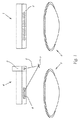
先ず図1について述べると、図1は、本発明の第1実施例を大まかな模式図として示している。図1において、またそれ以降の図においても、本発明の機能にとって本質的である部材だけが図示されている。当業者にとって十分に既知であり投光装置(例えば前照灯:ヘッドライト)のために必要でもある、ハウジングや調節装置などのような他の部材は、図面の見易さのために省略されている。 Referring first to FIG. 1, FIG. 1 shows a schematic diagram of a first embodiment of the present invention. In FIG. 1 and the subsequent figures, only members essential to the function of the present invention are shown. Other components, such as housings and adjustment devices, well known to those skilled in the art and also necessary for floodlights (eg headlights) are omitted for the sake of clarity of the drawing. ing.
図1の右側には、第1投光ユニット1を見ることができ、該第1投光ユニット1は、更に詳細に図示されて説明されるが、個々の光源、特にLEDによるアレイを有し、これらの光源は、個々に又はグループごとに個別に制御可能である。図1において個々の光源は、同様に非図示の個別光学系に割り当てられており、これらの個別光学系は、例えば導光体又はリフレクタの形式で構成されており、光出射面2において投光像を発生させ、該投光像は、光学系を用い、ここではレンズ3を用い、車道上へ投射可能である。 On the right side of FIG. 1 a first light projecting unit 1 can be seen, which is illustrated and described in more detail, but has an array of individual light sources, in particular LEDs. These light sources can be controlled individually or group by group. In FIG. 1, individual light sources are similarly assigned to individual optical systems (not shown), and these individual optical systems are configured, for example, in the form of light guides or reflectors. An image is generated, and the projected image can be projected onto the roadway using an optical system, here using the lens 3.
更に第2投光ユニット4、即ちレーザ式投光ユニット4が設けられており、該レーザ式投光ユニット4は、図1において左側に図示されており、本質的な構成部材として、レーザ光線6を発生させるレーザ光源5と、ここではマイクロミラーとして構成されている光線偏向ユニット7と、光変換ユニット(ライトコンバージョンユニット)8とを有する。この種の走査型のレーザ式投光ユニットは、既知であり、この際、レーザ光線6は、光線偏向ユニット7において1つの軸線又は2つの軸線の周りで振動(スウィング)するマイクロミラーにより、光変換ユニット8において、予設定可能な投光像を発生させ、該投光像は、更なる光学系、ここではレンズ9を用い、同様に車道上へ投射され、第1投光ユニット1により発生された投光像とまとめられ、車道上で1つの全投光像ないし全配光となる。
Further, a second light projecting unit 4, that is, a laser type light projecting unit 4 is provided. The laser type light projecting unit 4 is shown on the left side in FIG. , A light beam deflecting unit 7 configured here as a micromirror, and a light conversion unit (light conversion unit) 8. Such a scanning laser projection unit of this kind is known, in which the laser beam 6 is transmitted by a micromirror that oscillates (swings) around one or two axes in the beam deflection unit 7. In the
ここでは2つのレンズ3、9が図示されているが、このことは、別の光学系構成が使用可能であることを排除しているわけではない。つまり(投光方向において)両方のレンズ3、9の後方に更なる光学系、例えばレンズを配設することも可能であり、或いはリフレクタを利用する複数の光学系を使用することも可能である。 Although two lenses 3 and 9 are shown here, this does not exclude the possibility of using another optical system configuration. In other words, a further optical system, for example a lens, can be arranged behind both lenses 3, 9 (in the direction of light projection), or a plurality of optical systems using reflectors can be used. .
レーザ光源5は、例えば青色光を有するレーザ光線6を発生させることができ、この青色光は、光変換ユニット8の蛍光体(Phosphor)において白色光へ変換される。この例では、唯一のレーザ式投光ユニット4だけが図示されているが、少なくとも1つの更なるレーザユニットを使用することも勿論可能であり、該レーザユニットは、同じ光線偏向ユニットを介してか又は更なる光線偏向ユニットを介してレーザ光線を走査し、光変換ユニット8へと導く。
The laser light source 5 can generate a laser beam 6 having, for example, blue light, and this blue light is converted into white light in a phosphor of the
従来技術からも見て取れるように、光変換ユニット8の蛍光体層を(投光方向において)後方からレーザ光線を用いて付勢することも可能であり、この際、蛍光体において変換された光の放射は、前方へと行われる。
As can be seen from the prior art, the phosphor layer of the
図2には、本発明の第2実施例が示されており、この際、第1投光ユニット1は、有利な一実施形態としてより具体的に図示されており(図1のものと)比肩可能な部材には、同じ符号が使われている。第1投光ユニット1の前面部には、複数の個別光学系10が見て取れ、これらの個別光学系10は、ここではリフレクタ(反射器)として構成されており、それらの底部には、図2では見ることはできないが、光源、好ましくはLEDが配設されている。本実施例において投光ユニット1は、3行で上から2行分は8列(8スリット)ずつ、下1行分は28列(28スリット)で配設された光源を有し、それに対応する数の個別光学系10ないしリフレクタを有する。またここでは、第1投光ユニット1の光出射面の領域に光変換ユニット8が設けられており、該光変換ユニット8において、レーザ光源5により発生されたレーザ光線6は、光線偏向ユニット7の振動するマイクロミラーにより偏向され、走査を実行する。ここでは、レーザ式投光ユニット4は、レーザ光源5と、光線偏向ユニット7と、第1投光ユニット1に配設された光変換ユニット8とにより構成されている。
FIG. 2 shows a second embodiment of the invention, in which the first light projecting unit 1 is more specifically illustrated as an advantageous embodiment (with that of FIG. 1). The same symbols are used for members that can be compared. A plurality of individual
図1による第1実施例と比べ、ここでは、両方の投光ユニット1、4に対して共通の光学系11、即ちレンズが設けられており、該レンズは、複数の個別光学系10の出射面に位置する投光像と、走査するレーザ光線6により光変換ユニット8において決定された投光像とを1つにまとめ、車道上へ投射することが可能である。
Compared with the first embodiment according to FIG. 1, here, a common optical system 11, i.e. a lens, is provided for both light projecting units 1, 4, and this lens emits a plurality of individual
図3には、本発明による投光装置の第3実施例が模式的に図示されており、該第3実施例は、原理的に図2のものに対応し、この際、比肩可能な部材には、同じ符号が使われている。第1投光ユニット1は、ここでは、個々の光源13を有する光源ユニット12から成り、それらの光源13は、LEDとして実施されており、3列26行の形式で配設されている。この光源ユニット12ないし個々の光源13には、1次光学系14が割り当てられており、該1次光学系14は、LEDないし光源13の総数、ここでは78に対応するよう、個々の全反射導光体15を有し、これらの全反射導光体15は、前方に向かって延在し、光出射面16に通じている。この光出射面16には、ここでも光変換ユニット8が配設されており、該光変換ユニット8は、レーザ光線6により走査され、この際、単色のレーザ光が、車道照明のために使用可能な光(白色光)へ変換される。
FIG. 3 schematically shows a third embodiment of the light projecting device according to the present invention. The third embodiment corresponds in principle to that of FIG. The same code is used for. The 1st light projection unit 1 consists of the light source unit 12 which has each
図2及び図3による実施例においては、個別光源の光出射開口部の所定数分が、対応の蛍光体面を有する光変換ユニット8により覆われている。この際、図3における複数の個別光源13ないしLEDのスペクトル光分布を、これらの個別光源13ないしLEDが蛍光体に光線を通し、ないし蛍光体を発光へと励起させるように、光変換ユニット8の蛍光体へ適合させるという可能性があり、それにより図2及び図3に図示された面(光出射面及び蛍光体面)は、照明のために「失われる」ことはない。しかしまた対応の領域(蛍光体面の領域)を個々の光源によっては照明しないことも可能であり、この際には、この領域において個別光源を省略することも可能である。
In the embodiment according to FIGS. 2 and 3, a predetermined number of light exit openings of the individual light sources are covered with a
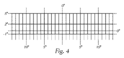
図4〜図6には、本発明による投光装置の3つの投光像が図示されており、この際、図4は、第1投光ユニットの投光像を単独で示しており、この際、この例において、垂直方向の照明は、−1°〜+5°の投射角で延在し、水平方向の照明は、左15°〜右15°の投射角で延在し、3列で各28行の分割形態が設けられている。この際、任意の分割を行うことが可能であり、例えば各列に同数の行を設ける必要はないことは、勿論明らかである。 4 to 6 show three projected images of the light projecting device according to the present invention. In this case, FIG. 4 shows a projected image of the first projecting unit alone, In this example, the vertical illumination extends with a projection angle of -1 ° to + 5 °, and the horizontal illumination extends with a projection angle of 15 ° left to 15 ° right, with three rows. Each of the 28 rows is divided. In this case, it is obvious that arbitrary division can be performed, and for example, it is not necessary to provide the same number of rows in each column.
図5は、第2レーザ式投光ユニットにより発生される投光像の一例を拡大尺度で示している。この際、水平方向の投射角範囲としては、左6°〜右6°が有利であり、垂直方向の投射角範囲としては、−1°〜+2°が有利であり、それは、これらの領域が、暗闇の中での走行時に運転者に対して必要不可欠な印象(光学的印象)の大部分を提供するためである。 FIG. 5 shows an example of a projection image generated by the second laser projection unit on an enlarged scale. At this time, the horizontal projection angle range is advantageously 6 ° to the left 6 °, and the vertical projection angle range is advantageously −1 ° to + 2 °. This is to provide most of the indispensable impression (optical impression) to the driver when driving in the dark.
これらの両方の投光像は、光学系3と光学系9又は光学系11により重ね合わせられ、車道上へ投射される1つの全投光像にまとめられる。それに対応する投光像が図6に示されており、図6からは、図4による投光像と図5による投光像の合成状態を見ることができ、図5に示された範囲の追加的な照明により、投光装置の機能性が遥かに向上され、それは、この範囲に対し、高解像度のレーザ式投光ユニットが使用可能であるためであり、該レーザ式投光ユニットは、例えば、全照明範囲において0.5°の垂直方向の解像度を可能とし、水平方向の範囲おいては0.1°の解像度を可能とする。 Both of these projected images are overlapped by the optical system 3 and the optical system 9 or the optical system 11 and are combined into one full projected image projected onto the roadway. The corresponding projected image is shown in FIG. 6, and from FIG. 6, the combined state of the projected image according to FIG. 4 and the projected image according to FIG. 5 can be seen, and the range of the range shown in FIG. With the additional illumination, the functionality of the projector is much improved because a high-resolution laser projector unit can be used for this range, the laser projector unit being For example, a vertical resolution of 0.5 ° is possible in the entire illumination range, and a resolution of 0.1 ° is possible in the horizontal range.
次に記載する値は、本発明の利点を更に強調するであろう。LEDに基づく個々のピクセルの照明最大値は、現在ほぼ80〜100ルクス(lx)であるが、この値は、ハイビームのためには比較的小さい値である。同様に例えば80〜100ルクス(lx)の最大値を達成するレーザ式投光ユニットとの組み合わせが行われると、ハイビーム最大値において180〜200ルクス(lx)の照明を提供するハイビームを得ることになり、このことは、良好な投光装置に対する現在の要求に適っている。 The values described below will further emphasize the advantages of the present invention. The maximum illumination value of individual pixels based on LEDs is currently approximately 80-100 lux (lx), but this value is relatively small for high beams. Similarly, when combined with a laser projection unit that achieves a maximum value of, for example, 80-100 lux (lx), a high beam providing illumination of 180-200 lux (lx) at a high beam maximum value is obtained. This meets the current demand for a good floodlight.
様々な投光像を重ね合わせることにより、色彩効果も混合可能であり、均質の同色の光像(投光像)を発生させることが可能である。 By superimposing various projected images, color effects can also be mixed, and a homogeneous light image of the same color (projected image) can be generated.
また両方の投光ユニットの組み合わせは、高い動的解像度に達することも可能とする。第1投光ユニット1の比較的「粗い」ピクセルにより、比較的大きな面が覆われるが、この面は、高解像度のレーザ式投光ユニット4により更に細分化されることになる。それにより極めて小さな範囲を直接的に制御することが可能であり、従って全システムの解像度は、既述のように、水平方向において0.1°よりも小さく、垂直方向において0.5°よりも小さくすることが可能である。 The combination of both light projecting units also makes it possible to reach a high dynamic resolution. A relatively large surface is covered by the relatively “rough” pixels of the first light projecting unit 1, but this surface will be further subdivided by the high resolution laser light projecting unit 4. This makes it possible to directly control a very small range, so that the overall system resolution is less than 0.1 ° in the horizontal direction and less than 0.5 ° in the vertical direction, as already mentioned. It can be made smaller.
上記の数値は、単なる例であり、これに関し、更に高い解像度の2次元レーザスキャナを使用することにより、更に良い値を得ることが可能である。 The above numerical values are merely examples, and it is possible to obtain better values in this regard by using a higher resolution two-dimensional laser scanner.
勿論、投光像が組み合わされる範囲を、その都度の要求に対応して任意に構成することも可能であり、このことは、決してハイビームに限定して想定されることではない。 Of course, the range in which the projected images are combined can be arbitrarily configured in response to each request, and this is not supposed to be limited to a high beam.
両方の投光ユニットの組み合わせにより、車速が比較的低速の場合には、レーザ式投光ユニット4による照明を省略することもでき、このことは、安全上の理由から有利であり、それは、例えば車両の停止時には、人間に対して恐らく危険ないし不愉快な、レーザ式投光ユニットにより放射される光が、放射されなくて済むからである。 If the vehicle speed is relatively low due to the combination of both light projecting units, the illumination by the laser light projecting unit 4 can be omitted, which is advantageous for safety reasons, for example This is because when the vehicle is stopped, the light emitted by the laser-type light projecting unit, which is probably dangerous or unpleasant for humans, does not have to be emitted.
最後に、両方の投光ユニットの組み合わせにより、レーザスキャナだけを基礎とした投光装置と比べ、有利な価格性能比が得られることを強調しておく。 Finally, it is emphasized that the combination of both light projecting units provides an advantageous price / performance ratio compared to a light projecting device based solely on a laser scanner.
1 第1投光ユニット
2 光出射面
3 レンズ
4 第2投光ユニット/レーザ式投光ユニット
5 レーザ光源
6 レーザ光線
7 光線偏向ユニット
8 光変換ユニット
9 レンズ
10 個別光学系
11 共通の光学系(レンズ)
12 光源ユニット
13 光源(LED)
14 1次光学系
15 全反射導光体
16 光出射面
DESCRIPTION OF SYMBOLS 1 1st light projection unit 2 Light-projection surface 3 Lens 4 2nd light projection unit / laser type light projection unit 5 Laser light source 6 Laser beam 7 Light
12
14 Primary optical system 15 Total reflection light guide 16 Light exit surface
Claims (10)
動的に可変の第1投光像を発生させるための少なくとも1つの光源(13)を有する第1投光ユニット(1)、並びに、少なくとも1つのレーザ光源(5)と、少なくとも1つの光線偏向ユニット(7)と、少なくとも1つの光変換ユニット(8)とを有する第2レーザ式投光ユニット(4)が設けられており、
前記第1投光ユニットにより発生された投光像と、前記第2レーザ式投光ユニットの前記光変換ユニットにおいて発生された投光像との両方の投光像を車道上の全配光にまとめるための光学系(3、9;11)が設けられており、
前記少なくとも1つの光線偏向ユニット(7)は、少なくとも1つの軸線の周りで旋回可能なマイクロミラーとして構成されていること
を特徴とする投光装置。 A vehicle projector having a plurality of light sources (5, 13) and an optical system (3, 9; 11) allocated to these light sources,
First projection unit (1) having at least one light source (13) for generating a dynamically variable first projection image, at least one laser light source (5), and at least one beam deflection A second laser type light projecting unit (4) having a unit (7) and at least one light conversion unit (8) is provided;
Projecting both the projected image generated by the first projector unit and the projected image generated by the light conversion unit of the second laser projector unit into the entire light distribution on the roadway An optical system (3, 9; 11) for summarizing is provided ,
The light projecting device, wherein the at least one light deflection unit (7) is configured as a micromirror that can turn around at least one axis .
を特徴とする、請求項1に記載の投光装置。 The projector according to claim 1, characterized in that the first light projecting unit (1) comprises a plurality of light sources (13) and individual optical systems (10; 15) assigned to the respective light sources. Optical device.
を特徴とする、請求項1又は2に記載の投光装置。 The optical system includes two separate optical system units (3, 9), and each of the light projecting units (1, 4) is assigned a respective optical system unit. Item 3. The light projecting device according to Item 1 or 2.
を特徴とする、請求項1又は2に記載の投光装置。 The optical system comprises a single common optical system unit (11), which is assigned to both light projecting units (1, 4). The light projecting device according to 2.
を特徴とする、請求項1〜4のいずれか一項に記載の投光装置。 The light projecting device according to claim 1, wherein at least one optical system unit (3, 9; 11) is configured as a lens.
を特徴とする、請求項1〜5のいずれか一項に記載の投光装置。 The at least one laser light source (5), the at least one light deflection unit (7), and the at least one light conversion unit (8) of the laser type light projecting unit (4) have one structure. The light projecting device according to claim 1, wherein the light projecting device is a unit.
を特徴とする、請求項1〜5のいずれか一項に記載の投光装置。 The at least one light conversion unit (8) of the laser type light projecting unit (4) is provided in a region of the light emitting surface (16) of the first light projecting unit (1). The light projection device according to any one of claims 1 to 5.
を特徴とする、請求項1〜7のいずれか一項に記載の投光装置。 The first light projecting unit (1) has a plurality of individual light sources (13) arranged in multiple columns of at least two rows, and these individual light sources are arranged in a dynamically variable manner on the roadway. The light projecting device according to any one of claims 1 to 7 , wherein the light projecting device is controllable to generate light.
を特徴とする、請求項1〜8のいずれか一項に記載の投光装置。 The at least one light deflection unit (7) is provided in the light conversion unit (8) to generate a dynamically variable projection image composed of segments that can be selectively illuminated. The light projection device according to any one of claims 1 to 8 .
を特徴とする、請求項1〜9のいずれか一項に記載の投光装置。 The light projector (1) according to any one of claims 1 to 9 , wherein the light source (13) of the first light projecting unit (1) is an LED.
Applications Claiming Priority (3)
| Application Number | Priority Date | Filing Date | Title |
|---|---|---|---|
| ATA50417/2013 | 2013-06-25 | ||
| ATA50417/2013A AT514333B1 (en) | 2013-06-25 | 2013-06-25 | Headlights for vehicles |
| PCT/AT2014/050123 WO2014205466A1 (en) | 2013-06-25 | 2014-05-26 | Headlights for motor vehicles |
Publications (2)
| Publication Number | Publication Date |
|---|---|
| JP2016524802A JP2016524802A (en) | 2016-08-18 |
| JP6018342B2 true JP6018342B2 (en) | 2016-11-02 |
Family
ID=51176009
Family Applications (1)
| Application Number | Title | Priority Date | Filing Date |
|---|---|---|---|
| JP2016520189A Active JP6018342B2 (en) | 2013-06-25 | 2014-05-26 | Floodlight device for vehicle |
Country Status (6)
| Country | Link |
|---|---|
| US (1) | US10101001B2 (en) |
| EP (1) | EP3014171B1 (en) |
| JP (1) | JP6018342B2 (en) |
| CN (1) | CN105308385A (en) |
| AT (1) | AT514333B1 (en) |
| WO (1) | WO2014205466A1 (en) |
Families Citing this family (36)
| Publication number | Priority date | Publication date | Assignee | Title |
|---|---|---|---|---|
| DE102013226614A1 (en) * | 2013-12-19 | 2015-06-25 | Osram Gmbh | lighting device |
| DE102014016332A1 (en) * | 2014-11-05 | 2016-05-12 | Audi Ag | Headlight for a motor vehicle and method for operating a headlight |
| KR20160069083A (en) * | 2014-12-05 | 2016-06-16 | 현대자동차주식회사 | Lamp for vehicle |
| JP6643645B2 (en) * | 2015-02-17 | 2020-02-12 | スタンレー電気株式会社 | Vehicle lighting |
| JP2016150668A (en) * | 2015-02-18 | 2016-08-22 | スタンレー電気株式会社 | Vehicle lamp fitting |
| JP6265183B2 (en) | 2015-08-21 | 2018-01-24 | トヨタ自動車株式会社 | Vehicle headlamp device |
| JP6683438B2 (en) * | 2015-08-25 | 2020-04-22 | スタンレー電気株式会社 | Vehicle headlight system |
| DE102015224692A1 (en) * | 2015-12-09 | 2017-06-14 | Osram Gmbh | LIGHT GENERATION WITH LIGHTING DIODE AND LASER |
| AT518090B1 (en) * | 2015-12-21 | 2017-10-15 | Zkw Group Gmbh | Headlight for a vehicle |
| AT518094B1 (en) * | 2015-12-21 | 2018-06-15 | Zkw Group Gmbh | Headlights for vehicles |
| DE102016201606A1 (en) * | 2016-02-03 | 2017-08-03 | Osram Gmbh | LIGHTING DEVICE FOR THE EMISSION OF LIGHTING LIGHT |
| FR3048061B1 (en) * | 2016-02-23 | 2019-04-05 | Valeo Vision | LIGHTING SYSTEM FOR MOTOR VEHICLE PROJECTOR COMPRISING LIGHTING MODULE WITH LIMITED ENCLOSURE |
| FR3054642B1 (en) * | 2016-07-29 | 2020-07-17 | Valeo Vision | MOTOR VEHICLE PROJECTOR LIGHTING MODULE WITH VARIABLE OPENING BEAM |
| DE102016216624A1 (en) * | 2016-09-02 | 2018-03-08 | Osram Gmbh | MODULE AND LIGHTING SYSTEM |
| DE102016217020A1 (en) * | 2016-09-07 | 2018-03-08 | Bayerische Motoren Werke Aktiengesellschaft | Headlight for a motor vehicle |
| CN108613104A (en) * | 2016-12-16 | 2018-10-02 | 常州星宇车灯股份有限公司 | A kind of novel array automobile headlamp light guide structure |
| FR3061538B1 (en) | 2017-01-02 | 2019-05-24 | Valeo Vision | LIGHTING DEVICE FOR A VEHICLE COMBINING TWO LIGHT SOURCES |
| AT519462B1 (en) * | 2017-01-24 | 2018-07-15 | Zkw Group Gmbh | vehicle headlights |
| WO2018149407A1 (en) * | 2017-02-14 | 2018-08-23 | 亿光电子工业股份有限公司 | Light-guiding component, light-guiding device, and lighting module |
| JP6879772B2 (en) * | 2017-02-22 | 2021-06-02 | 株式会社小糸製作所 | Vehicle lighting |
| DE102017205723A1 (en) | 2017-04-04 | 2018-10-04 | Volkswagen Aktiengesellschaft | Scanning headlight for a motor vehicle |
| AT519839B1 (en) * | 2017-04-11 | 2019-03-15 | Zkw Group Gmbh | VEHICLE HEADLIGHTS AND METHOD FOR SUPPORTING A PARKING PROCESS |
| FR3069045B1 (en) * | 2017-07-13 | 2019-10-04 | Valeo Vision | LIGHTING DEVICE PROJECTING TWO MATRIXES OF VERTICALLY LUMINOUS LIGHT PIXELS |
| US10295139B2 (en) * | 2017-08-23 | 2019-05-21 | Valeo North America, Inc. | Headlamp road-writing systems |
| CN108302485A (en) * | 2017-09-13 | 2018-07-20 | 上海小糸车灯有限公司 | Car light intelligent illuminating system, vehicle lamp assembly and automobile |
| JP6981174B2 (en) * | 2017-10-25 | 2021-12-15 | トヨタ自動車株式会社 | Vehicle headlight device |
| CN109724048B (en) * | 2017-10-30 | 2021-03-16 | 深圳市绎立锐光科技开发有限公司 | Light source system and automobile headlamp |
| EP3527876A1 (en) * | 2018-02-19 | 2019-08-21 | ZKW Group GmbH | Motor vehicle headlamp with light guides arranged in matrix form |
| FR3080670A1 (en) * | 2018-04-27 | 2019-11-01 | Valeo Vision | OPTICAL MODULE PROJECTING A PIXEL LUMINOUS BEAM |
| WO2020024595A1 (en) * | 2018-08-01 | 2020-02-06 | 深圳市绎立锐光科技开发有限公司 | Light source device and headlight system |
| JP7143716B2 (en) | 2018-10-10 | 2022-09-29 | 市光工業株式会社 | Vehicle light guide and vehicle lamp |
| EP3650744A1 (en) * | 2018-11-07 | 2020-05-13 | ZKW Group GmbH | Motor vehicle headlamp light module |
| WO2020216589A1 (en) * | 2019-04-25 | 2020-10-29 | Lumileds Holding B.V. | Holding collimator elements in a lighting arrangement |
| CN112240533A (en) * | 2019-07-19 | 2021-01-19 | 深圳市绎立锐光科技开发有限公司 | Lighting device and automobile headlamp |
| CN110454693A (en) * | 2019-08-14 | 2019-11-15 | 浙江比肯科技有限公司 | A kind of LED luminescence unit using laser enhancing |
| CN113124375A (en) * | 2020-01-15 | 2021-07-16 | 华域视觉科技(上海)有限公司 | Vehicle lighting device, vehicle lamp and vehicle |
Family Cites Families (33)
| Publication number | Priority date | Publication date | Assignee | Title |
|---|---|---|---|---|
| US4868718A (en) | 1989-03-13 | 1989-09-19 | General Electric Company | Forward illumination lighting system for vehicles |
| DE19737653A1 (en) | 1997-08-29 | 1999-03-04 | Patent Treuhand Ges Fuer Elektrische Gluehlampen Mbh | Lighting device for vehicles and operating method for such a lighting device |
| JP2001010403A (en) | 1999-06-30 | 2001-01-16 | Kanto Auto Works Ltd | Automotive headlamp |
| DE10114123A1 (en) * | 2001-03-22 | 2002-09-26 | Hella Kg Hueck & Co | Headlights for vehicles |
| DE10130809A1 (en) * | 2001-06-26 | 2003-01-02 | Hella Kg Hueck & Co | Headlights for vehicles |
| US7156542B2 (en) | 2002-12-13 | 2007-01-02 | Ford Global Technologies, Llc | Vehicle headlight system having digital beam-forming optics |
| JP4717533B2 (en) * | 2005-07-06 | 2011-07-06 | 株式会社 日立ディスプレイズ | Display device |
| JP4786420B2 (en) | 2006-05-31 | 2011-10-05 | 株式会社小糸製作所 | Vehicle lamp unit |
| JP4812543B2 (en) * | 2006-06-28 | 2011-11-09 | 株式会社小糸製作所 | Vehicle lighting |
| JP4881255B2 (en) * | 2007-08-13 | 2012-02-22 | 株式会社小糸製作所 | Vehicle headlamp |
| KR101503390B1 (en) | 2008-03-03 | 2015-03-17 | 가부시키가이샤후지쿠라 | Door mirror device |
| DE102008013603B4 (en) * | 2008-03-11 | 2017-06-22 | Automotive Lighting Reutlingen Gmbh | Light module for a lighting device |
| DE102008025397A1 (en) | 2008-05-28 | 2009-12-24 | Osram Gesellschaft mit beschränkter Haftung | Vehicle lighting device with at least two semiconductor lighting elements |
| JP2010083211A (en) | 2008-09-29 | 2010-04-15 | Toyoda Gosei Co Ltd | Lighting system for vehicle interior |
| JP2010092747A (en) * | 2008-10-09 | 2010-04-22 | Koito Mfg Co Ltd | Vehicle headlamp |
| JP5266605B2 (en) * | 2009-03-27 | 2013-08-21 | スタンレー電気株式会社 | Vehicle lighting |
| JP5577138B2 (en) * | 2010-04-08 | 2014-08-20 | スタンレー電気株式会社 | Vehicle headlamp |
| DE102010028949A1 (en) | 2010-05-12 | 2011-11-17 | Osram Gesellschaft mit beschränkter Haftung | headlight module |
| JP5527058B2 (en) | 2010-07-06 | 2014-06-18 | セイコーエプソン株式会社 | Light source device and projector |
| US8708537B2 (en) * | 2010-08-31 | 2014-04-29 | Sharp Kabushiki Kaisha | Lighting apparatus, headlamp, and mobile body |
| JP5487077B2 (en) * | 2010-10-29 | 2014-05-07 | シャープ株式会社 | Light emitting device, vehicle headlamp and lighting device |
| JP2012169050A (en) * | 2011-02-10 | 2012-09-06 | Stanley Electric Co Ltd | Lamp for vehicle |
| WO2012121343A1 (en) * | 2011-03-08 | 2012-09-13 | シャープ株式会社 | Light-emitting device, illumination device, vehicle headlight, projector, and method for manufacturing light-emitting device |
| DE102011001865B4 (en) | 2011-04-07 | 2021-10-21 | HELLA GmbH & Co. KGaA | Lighting device |
| JP5722702B2 (en) * | 2011-05-19 | 2015-05-27 | スタンレー電気株式会社 | Vehicle lighting |
| JP5818134B2 (en) * | 2011-05-24 | 2015-11-18 | スタンレー電気株式会社 | Vehicle headlamp |
| JP2013012358A (en) * | 2011-06-28 | 2013-01-17 | Sharp Corp | Lighting device, and vehicular headlamp |
| JP2013047091A (en) * | 2011-07-25 | 2013-03-07 | Sharp Corp | Lighting device and vehicle headlamp including the same |
| DE102011054234B4 (en) | 2011-10-06 | 2020-03-12 | HELLA GmbH & Co. KGaA | Lighting device |
| DE102012008833B4 (en) | 2012-04-28 | 2018-12-27 | Daimler Ag | Lighting arrangement and vehicle headlights |
| DE102013200925A1 (en) | 2013-01-22 | 2014-07-24 | Automotive Lighting Reutlingen Gmbh | Light source unit for vehicle headlights |
| AT514834B1 (en) * | 2013-02-07 | 2017-11-15 | Zkw Group Gmbh | Headlight for a motor vehicle and method for generating a light distribution |
| EP2796949A1 (en) | 2013-04-24 | 2014-10-29 | ETA SA Manufacture Horlogère Suisse | Method for handling an electronic device |
-
2013
- 2013-06-25 AT ATA50417/2013A patent/AT514333B1/en not_active IP Right Cessation
-
2014
- 2014-05-26 JP JP2016520189A patent/JP6018342B2/en active Active
- 2014-05-26 WO PCT/AT2014/050123 patent/WO2014205466A1/en active Application Filing
- 2014-05-26 EP EP14738353.3A patent/EP3014171B1/en active Active
- 2014-05-26 US US14/898,188 patent/US10101001B2/en active Active
- 2014-05-26 CN CN201480035836.3A patent/CN105308385A/en active Pending
Also Published As
| Publication number | Publication date |
|---|---|
| AT514333B1 (en) | 2014-12-15 |
| US10101001B2 (en) | 2018-10-16 |
| JP2016524802A (en) | 2016-08-18 |
| EP3014171B1 (en) | 2020-07-01 |
| CN105308385A (en) | 2016-02-03 |
| WO2014205466A1 (en) | 2014-12-31 |
| EP3014171A1 (en) | 2016-05-04 |
| AT514333A4 (en) | 2014-12-15 |
| US20160146419A1 (en) | 2016-05-26 |
Similar Documents
| Publication | Publication Date | Title |
|---|---|---|
| JP6018342B2 (en) | Floodlight device for vehicle | |
| US10598330B2 (en) | Headlight for vehicles | |
| JP6133442B2 (en) | Automotive headlight and light distribution generation method | |
| US9777901B2 (en) | Headlight for a motor vehicle and method for distributing light | |
| KR102355254B1 (en) | Lighting arrangement | |
| US20190017671A1 (en) | Pixelated projection for automotive headlamp | |
| US9677736B2 (en) | Adaptive lighting system for an automobile vehicle | |
| CN105698087B (en) | Lighting module and headlamp provided with such a module | |
| US10670220B2 (en) | Method for controlling a laser illumination device for a motor vehicle headlight | |
| CN108266696B (en) | Lighting device for vehicle combining two light sources | |
| US20150176809A1 (en) | Lighting device with phosphor surface | |
| US10591130B2 (en) | Light-beam-projecting device comprising a digital screen and headlamp equipped with such a device | |
| JP6952200B2 (en) | Light module for automobile floodlights | |
| CN112236617B (en) | Matrix array monolithic motor vehicle lighting device for writing on the ground | |
| US20180259156A1 (en) | Lighting system and a lighting method | |
| US10696219B2 (en) | Interior lighting system for a motor vehicle | |
| JP2021503158A (en) | Lighting device with a spatially controllable reflector element | |
| US10698303B2 (en) | Projection apparatus for producing a pixel-based illumination pattern | |
| US20180245762A1 (en) | Lighting Apparatus, in Particular for a Motor Vehicle | |
| US10962192B2 (en) | Illumination device for a motor vehicle | |
| JP2009128689A5 (en) | ||
| US11098871B2 (en) | Headlamp for vehicles | |
| JP2017531902A (en) | Lighting device comprising two areas for a vehicle and a light equipped with such a lighting device | |
| WO2019098041A1 (en) | Vehicle light fixture | |
| CN109661539B (en) | Front shining lamp |
Legal Events
| Date | Code | Title | Description |
|---|---|---|---|
| TRDD | Decision of grant or rejection written | ||
| A01 | Written decision to grant a patent or to grant a registration (utility model) |
Free format text: JAPANESE INTERMEDIATE CODE: A01 Effective date: 20160913 |
|
| A61 | First payment of annual fees (during grant procedure) |
Free format text: JAPANESE INTERMEDIATE CODE: A61 Effective date: 20160929 |
|
| R150 | Certificate of patent or registration of utility model |
Ref document number: 6018342 Country of ref document: JP Free format text: JAPANESE INTERMEDIATE CODE: R150 |
|
| R250 | Receipt of annual fees |
Free format text: JAPANESE INTERMEDIATE CODE: R250 |
|
| R250 | Receipt of annual fees |
Free format text: JAPANESE INTERMEDIATE CODE: R250 |
|
| R250 | Receipt of annual fees |
Free format text: JAPANESE INTERMEDIATE CODE: R250 |
|
| R250 | Receipt of annual fees |
Free format text: JAPANESE INTERMEDIATE CODE: R250 |
|
| R250 | Receipt of annual fees |
Free format text: JAPANESE INTERMEDIATE CODE: R250 |