JP2017531902A - Lighting device comprising two areas for a vehicle and a light equipped with such a lighting device - Google Patents
Lighting device comprising two areas for a vehicle and a light equipped with such a lighting device Download PDFInfo
- Publication number
- JP2017531902A JP2017531902A JP2017517725A JP2017517725A JP2017531902A JP 2017531902 A JP2017531902 A JP 2017531902A JP 2017517725 A JP2017517725 A JP 2017517725A JP 2017517725 A JP2017517725 A JP 2017517725A JP 2017531902 A JP2017531902 A JP 2017531902A
- Authority
- JP
- Japan
- Prior art keywords
- light
- light beam
- dispersion region
- transmission surface
- dispersion
- Prior art date
- Legal status (The legal status is an assumption and is not a legal conclusion. Google has not performed a legal analysis and makes no representation as to the accuracy of the status listed.)
- Pending
Links
Images


Classifications
-
- B—PERFORMING OPERATIONS; TRANSPORTING
- B60—VEHICLES IN GENERAL
- B60Q—ARRANGEMENT OF SIGNALLING OR LIGHTING DEVICES, THE MOUNTING OR SUPPORTING THEREOF OR CIRCUITS THEREFOR, FOR VEHICLES IN GENERAL
- B60Q1/00—Arrangement of optical signalling or lighting devices, the mounting or supporting thereof or circuits therefor
- B60Q1/26—Arrangement of optical signalling or lighting devices, the mounting or supporting thereof or circuits therefor the devices being primarily intended to indicate the vehicle, or parts thereof, or to give signals, to other traffic
- B60Q1/2607—Arrangement of optical signalling or lighting devices, the mounting or supporting thereof or circuits therefor the devices being primarily intended to indicate the vehicle, or parts thereof, or to give signals, to other traffic comprising at least two indicating lamps
-
- F—MECHANICAL ENGINEERING; LIGHTING; HEATING; WEAPONS; BLASTING
- F21—LIGHTING
- F21S—NON-PORTABLE LIGHTING DEVICES; SYSTEMS THEREOF; VEHICLE LIGHTING DEVICES SPECIALLY ADAPTED FOR VEHICLE EXTERIORS
- F21S41/00—Illuminating devices specially adapted for vehicle exteriors, e.g. headlamps
- F21S41/10—Illuminating devices specially adapted for vehicle exteriors, e.g. headlamps characterised by the light source
- F21S41/14—Illuminating devices specially adapted for vehicle exteriors, e.g. headlamps characterised by the light source characterised by the type of light source
-
- F—MECHANICAL ENGINEERING; LIGHTING; HEATING; WEAPONS; BLASTING
- F21—LIGHTING
- F21S—NON-PORTABLE LIGHTING DEVICES; SYSTEMS THEREOF; VEHICLE LIGHTING DEVICES SPECIALLY ADAPTED FOR VEHICLE EXTERIORS
- F21S41/00—Illuminating devices specially adapted for vehicle exteriors, e.g. headlamps
- F21S41/60—Illuminating devices specially adapted for vehicle exteriors, e.g. headlamps characterised by a variable light distribution
- F21S41/67—Illuminating devices specially adapted for vehicle exteriors, e.g. headlamps characterised by a variable light distribution by acting on reflectors
- F21S41/675—Illuminating devices specially adapted for vehicle exteriors, e.g. headlamps characterised by a variable light distribution by acting on reflectors by moving reflectors
-
- F—MECHANICAL ENGINEERING; LIGHTING; HEATING; WEAPONS; BLASTING
- F21—LIGHTING
- F21S—NON-PORTABLE LIGHTING DEVICES; SYSTEMS THEREOF; VEHICLE LIGHTING DEVICES SPECIALLY ADAPTED FOR VEHICLE EXTERIORS
- F21S43/00—Signalling devices specially adapted for vehicle exteriors, e.g. brake lamps, direction indicator lights or reversing lights
- F21S43/10—Signalling devices specially adapted for vehicle exteriors, e.g. brake lamps, direction indicator lights or reversing lights characterised by the light source
- F21S43/13—Signalling devices specially adapted for vehicle exteriors, e.g. brake lamps, direction indicator lights or reversing lights characterised by the light source characterised by the type of light source
- F21S43/14—Light emitting diodes [LED]
-
- F—MECHANICAL ENGINEERING; LIGHTING; HEATING; WEAPONS; BLASTING
- F21—LIGHTING
- F21S—NON-PORTABLE LIGHTING DEVICES; SYSTEMS THEREOF; VEHICLE LIGHTING DEVICES SPECIALLY ADAPTED FOR VEHICLE EXTERIORS
- F21S43/00—Signalling devices specially adapted for vehicle exteriors, e.g. brake lamps, direction indicator lights or reversing lights
- F21S43/10—Signalling devices specially adapted for vehicle exteriors, e.g. brake lamps, direction indicator lights or reversing lights characterised by the light source
- F21S43/13—Signalling devices specially adapted for vehicle exteriors, e.g. brake lamps, direction indicator lights or reversing lights characterised by the light source characterised by the type of light source
- F21S43/16—Light sources where the light is generated by photoluminescent material spaced from a primary light generating element
-
- F—MECHANICAL ENGINEERING; LIGHTING; HEATING; WEAPONS; BLASTING
- F21—LIGHTING
- F21S—NON-PORTABLE LIGHTING DEVICES; SYSTEMS THEREOF; VEHICLE LIGHTING DEVICES SPECIALLY ADAPTED FOR VEHICLE EXTERIORS
- F21S43/00—Signalling devices specially adapted for vehicle exteriors, e.g. brake lamps, direction indicator lights or reversing lights
- F21S43/20—Signalling devices specially adapted for vehicle exteriors, e.g. brake lamps, direction indicator lights or reversing lights characterised by refractors, transparent cover plates, light guides or filters
- F21S43/26—Refractors, transparent cover plates, light guides or filters not provided in groups F21S43/235 - F21S43/255
-
- F—MECHANICAL ENGINEERING; LIGHTING; HEATING; WEAPONS; BLASTING
- F21—LIGHTING
- F21S—NON-PORTABLE LIGHTING DEVICES; SYSTEMS THEREOF; VEHICLE LIGHTING DEVICES SPECIALLY ADAPTED FOR VEHICLE EXTERIORS
- F21S43/00—Signalling devices specially adapted for vehicle exteriors, e.g. brake lamps, direction indicator lights or reversing lights
- F21S43/30—Signalling devices specially adapted for vehicle exteriors, e.g. brake lamps, direction indicator lights or reversing lights characterised by reflectors
- F21S43/31—Optical layout thereof
-
- F—MECHANICAL ENGINEERING; LIGHTING; HEATING; WEAPONS; BLASTING
- F21—LIGHTING
- F21S—NON-PORTABLE LIGHTING DEVICES; SYSTEMS THEREOF; VEHICLE LIGHTING DEVICES SPECIALLY ADAPTED FOR VEHICLE EXTERIORS
- F21S43/00—Signalling devices specially adapted for vehicle exteriors, e.g. brake lamps, direction indicator lights or reversing lights
- F21S43/40—Signalling devices specially adapted for vehicle exteriors, e.g. brake lamps, direction indicator lights or reversing lights characterised by the combination of reflectors and refractors
-
- F—MECHANICAL ENGINEERING; LIGHTING; HEATING; WEAPONS; BLASTING
- F21—LIGHTING
- F21Y—INDEXING SCHEME ASSOCIATED WITH SUBCLASSES F21K, F21L, F21S and F21V, RELATING TO THE FORM OR THE KIND OF THE LIGHT SOURCES OR OF THE COLOUR OF THE LIGHT EMITTED
- F21Y2115/00—Light-generating elements of semiconductor light sources
- F21Y2115/10—Light-emitting diodes [LED]
-
- F—MECHANICAL ENGINEERING; LIGHTING; HEATING; WEAPONS; BLASTING
- F21—LIGHTING
- F21Y—INDEXING SCHEME ASSOCIATED WITH SUBCLASSES F21K, F21L, F21S and F21V, RELATING TO THE FORM OR THE KIND OF THE LIGHT SOURCES OR OF THE COLOUR OF THE LIGHT EMITTED
- F21Y2115/00—Light-generating elements of semiconductor light sources
- F21Y2115/30—Semiconductor lasers
Abstract
本発明は、光線を透過可能な透過面(3)と、透過面(3)の方向に光ビームを形成するために光線を放出可能な少なくとも1つの光源とを含む、特に自動車向けの、2つの領域を含む点灯装置に関する。装置は、透過面(3)の第1の分散領域(10)に光ビームを分配し、かつ、透過面(3)の第2の分散領域(11)に光ビームを分配するように構成された分配手段も含み、第1の分散領域(10)が、第1の開口角で光ビームを透過可能であり、第2の分散領域(11)が、第2の開口角で光ビームを透過可能である。The present invention comprises a transmissive surface (3) capable of transmitting light and at least one light source capable of emitting light to form a light beam in the direction of the transmissive surface (3). The present invention relates to a lighting device including one region. The apparatus is configured to distribute the light beam to the first dispersion region (10) of the transmission surface (3) and to distribute the light beam to the second dispersion region (11) of the transmission surface (3). The first dispersion region (10) can transmit the light beam at the first opening angle, and the second dispersion region (11) transmits the light beam at the second opening angle. Is possible.
Description
本発明は、自動車向けの、2つの領域を含む点灯装置、およびそのような点灯装置を備えたライト、特にフォグライトに関する。 The present invention relates to a lighting device for a motor vehicle comprising two regions and a light, in particular a fog light, equipped with such a lighting device.
一般的に車両の後方に位置する自動車ライトは、1つまたは複数の光源と、光を閉じるアウターレンズとを含む点灯装置である。簡単に言うと、光源は、車両の外側へ光を透過させる光斑を生成するために、光線を放出して、アウターレンズに向けて方向付けられる光ビームを形成する。光斑の色は、ライトの機能または種類を表す。すなわち、白色の光斑は、ライトが後退灯であることを示し、黄色の光斑は方向指示器であり、赤色の光斑は、後方灯またはブレーキ灯であり、ブレーキ灯は、より大きな光度であることが知られている。霧、大雨、または雪などの困難な気象条件下でも目に見えるように、強度がより大きな赤いフォグライトも存在する。色に加えて、これらのライトは、特に光度および視野に関する規制に従わなければならない。 In general, an automobile light located behind a vehicle is a lighting device that includes one or more light sources and an outer lens that closes the light. Briefly, the light source emits a light beam to form a light beam that is directed toward the outer lens to produce a light spot that transmits light outside the vehicle. The color of the light spot represents the function or type of light. That is, a white light spot indicates that the light is a backward light, a yellow light spot is a direction indicator, a red light spot is a rear light or a brake light, and a brake light is a greater light intensity It has been known. There are also more intense red fog lights that are visible even under difficult weather conditions such as fog, heavy rain, or snow. In addition to color, these lights must comply with regulations regarding light intensity and field of view in particular.
したがって、車両の後部は、複数の光斑を含み、各光斑は、各機能に特化した色を有する。光源は、ライトの種類に関連して選択された光度を有する。光斑のそれぞれが、少なくとも1つの異なる光源によってさらに生成され、車両の点灯装置の数が増加する。光源は、例えば、発光ダイオードである。特に、光源が、発光ダイオードまたはレーザダイオードである場合、これらの多数の光源は、ライトの製造コストに影響を与える。 Therefore, the rear part of the vehicle includes a plurality of light spots, and each light spot has a color specific to each function. The light source has a light intensity selected in relation to the type of light. Each of the light spots is further generated by at least one different light source, increasing the number of lighting devices in the vehicle. The light source is, for example, a light emitting diode. In particular, when the light source is a light emitting diode or a laser diode, these multiple light sources affect the manufacturing cost of the light.
光斑の構成および配置もまた制限されることがあり、光源が、何らかの他の機能向けの光斑を生成することなく、対応する光斑を生成することを確保する必要があるために、得るのが難しい光斑の構成もある。 The configuration and placement of the light spots can also be limited and difficult to obtain because it is necessary to ensure that the light source produces a corresponding light spot without producing a light spot for any other function There is also a configuration of light spots.
したがって、本発明は、車両の光源の数を減少させ、種々のライトの配置および設計に新たな可能性を提供するように構成された点灯装置を製造することを目的とする。 Accordingly, it is an object of the present invention to produce a lighting device configured to reduce the number of light sources in a vehicle and provide new possibilities for various light arrangements and designs.
この目的を達成するために、本発明は、光線を透過可能な透過面と、透過面の方向に光ビームを形成するために光線を放出可能な少なくとも1つの光源と、を含む、特に自動車向けの、2つの領域を含む点灯装置に関する。 To achieve this object, the present invention comprises a transmissive surface capable of transmitting light and at least one light source capable of emitting light to form a light beam in the direction of the transmissive surface, particularly for automobiles. The present invention relates to a lighting device including two regions.
装置は、また、透過面の第1の分散領域に光ビームを分配し、かつ、透過面の第2の分散領域に光ビームを分配するように構成される分配手段を含み、第1の分散領域が、第1の開口角で光ビームを透過可能であり、第2の分散領域が、第2の開口角で光ビームを透過可能であるという点において、注目に値する。 The apparatus also includes distribution means configured to distribute the light beam to the first dispersion region of the transmission surface and to distribute the light beam to the second dispersion region of the transmission surface, the first dispersion It is noteworthy in that the region can transmit the light beam at the first aperture angle and the second dispersion region can transmit the light beam at the second aperture angle.
したがって、装置は、1つまたは複数の同一の光源を使用して、2つの異なる分散領域を照らす。したがって、これは、異なる機能ごとに光源の数を増加させる必要性を回避する。実際に、各分散領域は、異なる機能を実現することができ、分配手段は、光源から領域のいずれか一方に向けて光ビームを方向付ける役割を果たす。 Thus, the device uses two or more identical light sources to illuminate two different dispersed regions. This thus avoids the need to increase the number of light sources for different functions. In practice, each dispersion region can perform a different function, and the distribution means serve to direct the light beam from the light source towards one of the regions.
さらに、装置によって、光斑を配列すること、および新たなライトの設計を創作することが容易であり、光斑に対する光源の、必要とされる配置で問題は生じない。したがって、装置は、ライトの設計を簡易化する。 Furthermore, the device makes it easy to arrange the light spots and to create a new light design, with no problems in the required arrangement of the light sources relative to the light spots. Thus, the device simplifies the light design.
本発明の種々の実施形態によれば、個別に、または組み合わせて、
− 第1の開口角と第2の開口角とは、異なる値を有し、
− 分配手段は、眼で感知できない周波数で、第1の領域および第2の領域に、交互に光ビームを分配するように構成され、
− 第1の分散領域および/または第2の分散領域は、分散パターンを含み、
− 分散パターンは、透過面に均一に分布されたクッション形状を有し、
− クッションは、曲率を有し、
− クッションの曲率は、一定の曲率半径を有し、
− 第1の領域のクッションと第2の領域のクッションとは、異なる曲率半径を有し、
− 第1の分散領域および/または第2の分散領域は、ホログラフィックパターンを含み、
− 分配手段は、ビームが分配される分散領域の大きさに対応するスイープ幅で、透過面をスイープするように構成された、透過面をスイープする手段であり、
− スイープする手段が、第1の方向、および/または第1の方向に対して実質的に垂直な第2の方向に、光ビームで透過面をスイープするように構成された1つまたは2つの可動マイクロミラーを含み、
− 光源は、少なくとも1つのレーザダイオードを含み、
− 分配手段は、マイクロミラーのマトリクスからなり、
− 光源は、少なくとも1つの発光ダイオードを含み、
− 光源は、一定の光強度であり、
− 上記装置は、光ビームを形成するために光源から結合する光線をコリメートするように構成された光学システムを含み、
− 上記装置は、透過面を含むアウターレンズを含む。
According to various embodiments of the invention, individually or in combination,
The first opening angle and the second opening angle have different values;
The distribution means is arranged to alternately distribute the light beam to the first region and the second region at a frequency not perceptible by the eye;
The first dispersion region and / or the second dispersion region comprises a dispersion pattern;
The dispersion pattern has a cushion shape that is uniformly distributed on the transmission surface;
-The cushion has a curvature;
-The curvature of the cushion has a constant radius of curvature;
The cushion of the first region and the cushion of the second region have different radii of curvature;
The first dispersion region and / or the second dispersion region comprises a holographic pattern;
The distribution means is means for sweeping the transmission surface, configured to sweep the transmission surface with a sweep width corresponding to the size of the dispersion region to which the beam is distributed;
One or two means for sweeping are configured to sweep the transmission surface with the light beam in a first direction and / or in a second direction substantially perpendicular to the first direction; Including movable micromirrors,
The light source comprises at least one laser diode;
The distribution means consists of a matrix of micromirrors;
The light source comprises at least one light emitting diode;
-The light source has a constant light intensity;
The apparatus comprises an optical system configured to collimate light rays that combine from the light source to form a light beam;
The device comprises an outer lens comprising a transmission surface;
本発明は、また、2つの領域を含むこの種の点灯装置を含むライトにも関する。 The invention also relates to a light comprising such a lighting device comprising two regions.
本発明は、非限定的な例として与えられ、添付図面を伴う以下の説明に照らしてより良好に理解されるであろう。 The invention will be better understood in the light of the following description, given as a non-limiting example and accompanied with the accompanying drawings, in which:
図1および図2は、本発明に係る点灯装置1を含む自動車ライト、例えば後方灯の一実施形態を示している。点灯装置1は、光線を放出して光ビームを形成するように適合された光源2と、光線を透過するように適合された透過面3とを含む。光源は、一定の光強度であることが好ましいが、必要とされるライトの機能によっては可変の光強度であってもよい。
1 and 2 show an embodiment of an automobile light, for example a rear lamp, including a lighting device 1 according to the present invention. The lighting device 1 includes a
透過面3は、例えば、光を閉じるアウターレンズ6上にある。図1および図2に示される第1の変形例では、透過面3は、アウターレンズ6の内面である。それは、アウターレンズ6から離れた構成要素、例えば、アウターレンズ6の正面のライトの内側の透過スクリーンであってもよい。光源2から発する光ビームは、透過面3を照光する。
The transmission surface 3 is, for example, on the
図1および図2の実施形態では、光源2は、例えば、ライトの機能に対応する色をアウターレンズ6上に生成するために選択された波長で放出するレーザダイオードを含むレーザ光源である。あるいは、光ビームの経路上の波長変換装置、例えば、蛍光体プレートが、レーザ照射の波長を変換して必要とされる色を生成する。光源2は、また、例えば、光ファイバ、異なるレーザ光源、またはダイクロックミラーの異なる偏光を利用する装置を使用して、複数のレーザビームを単一のビームに結合する光学装置を含んでもよい。
In the embodiment of FIGS. 1 and 2, the
図示されていない第2実施形態では、光源2は、1つまたは複数の発光ダイオードで構成される。
In the second embodiment (not shown), the
これらの2つの実施形態では、装置1は、光ビームを形成するために、光源2から光線をコリメートするように構成された光学システム5を含む。光学システム5は、例えば、単一のコリメータレンズであり、リフレクタも含んでいてもよい。
In these two embodiments, the apparatus 1 includes an
選択された光源2および光学システム5によって、光ビームは、スポット形状、大きな斑点の形状、または長方形マークさえも、光跡を透過面3上に投射することができる。
Depending on the
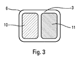
本発明によれば、図3および図4に示されるように、透過面3は、光を閉じるアウターレンズ6上にあり、少なくとも2つの分散領域、すなわち、第1の開口角12で光ビームを透過するように適合された第1の分散領域10と、第2の開口角13で光ビームを透過するように適合された第2の分散領域11とを含む。本発明では、より多くの数の領域、および、したがってそれと同じ数の対応する機能が、同様に想定され得る。
According to the present invention, as shown in FIGS. 3 and 4, the transmission surface 3 is on the
各分散領域は、ライトの異なる機能に対応する。例えば、第1の領域10は、フォグライトに対応することができ、第2の領域11は、走行灯に対応することができる。しかし、ライトの機能の他の組合せおよび選択も可能である。
Each distributed area corresponds to a different function of the light. For example, the
領域10、11を分散させるために、領域10、11は、例えば、透過面3に分配された分散パターンを含む。それによって、光ビームのコリメートされた光線が、透過面3に当たって通過するとき、それらは、四方に分散される。分散パターンの大きさは、ライトの機能を提供するために選択される。各機能は、光ビームの強度および投射角度に関する規定に従わなければならない。分散されたビームが、各領域を出る際に異なる開口角を有するように、各領域のパターンは異なる。分散パターンは、透過面3の2つの領域10、11のうちのそれぞれに均一に分布されることが好ましい。
In order to disperse the
図5に示されるように、それぞれが、例えば、一定の曲率半径で、ここでは凸状の、曲率を有するクッション(cushions)9の形状を有する。クッション9は、0.3から2mmまでの長さ14の湾曲した辺を有することが好ましい、実質的に四角形である。図6は、通過する光線を曲率が偏向させる、クッション9の出口面を示す。偏向は、クッション9の軸15に対して角度αをもたらす。クッション9の曲率は、必要とされる角度α、ならびにその結果必要とされる第1の開口角および第2の開口角に応じて選択される。第1の領域および第2の領域のクッションは、例えば、異なる曲率半径を有する。
As shown in FIG. 5, each has, for example, the shape of a
ホログラフィックパターンなどの、他の分散パターンが使用されてもよい。ホログラフィックパターンは、第1の領域および/または第2の領域を通過する光ビームを分散させるように構成される。 Other distributed patterns such as holographic patterns may be used. The holographic pattern is configured to disperse the light beam passing through the first region and / or the second region.
装置1は、透過面3の第1の分散領域10および/または第2の分散領域11に光ビームを分配するように構成される、分配手段をさらに含む。換言すると、分配手段は、ライトの第1の機能を生成するための第1の分散領域10と、ライトの第2の機能を生成するための第2の分散領域11のいずれか一方に、または、第1の領域10と第2の領域11とに交互に、光ビームを方向付けることを可能にする。後者の場合、2つの領域10、11が照光され、2つの機能が同時に使用される。交互の分配は、眼で感知できない周波数で行われることが好ましい。それによって、観察者は、2つの領域が同時に照光されると錯覚する。
The apparatus 1 further comprises a distribution means configured to distribute the light beam to the
図4に示すように、第1の分散領域10は、第1の開口角12で光ビームを透過し、第2の分散領域11は、第2の開口角13で光ビームを透過する。各開口角12、13は、ライトの1つの機能に対応する。この例では、第1の機能はフォグライトであり、第2の機能は、後方走行灯であり、第1の開口角12は、第2の開口角13よりも小さい。したがって、光強度が一定の光源である場合、第1の分散領域10を出る光ビームは、第2の分散領域11を出る光ビームよりも強い。
As shown in FIG. 4, the
レーザを使用する図1および図2の第1実施形態では、分配手段は、光ビームで透過面3をスイープするように構成されたスイープ手段4からなる。スイープは、人間の眼が、透過面3上での光点の動きを感知せず、アウターレンズ6のスイープされた部分の実質的に一定かつ均一な照光を観察するのに十分な高速度で実行される。スイープは、選択された領域10、11上で行われる。2つの領域10、11を同時に照光する場合、領域は、繰り返しプロセスによって、交互に、全体的または部分的(例えば、列をなして)のいずれかでスイープされる。スイープ手段4は、そのとき、各領域を個々にスイープすること、および、人間の目が感知することなく1つの領域から他の領域へ移動することの両方に十分な、スイープ周波数を有する。
In the first embodiment of FIGS. 1 and 2 using a laser, the distribution means comprises a sweep means 4 configured to sweep the transmission surface 3 with a light beam. The sweep is fast enough to allow the human eye not to sense the movement of the light spot on the transmission surface 3 and to observe a substantially constant and uniform illumination of the swept portion of the
レーザ光源を使用するこの実施形態では、透過面3は、好適には、スイープ手段4の故障の場合に、ビームの十分な分散をもたらすように構成され得る。実際には、スイープが中断される場合、レーザビームは、一方向に固定される。したがって、少なくともライトからのある距離から、観察者、特に観察者の眼に関して、安全を確保することが必要である。分散は、好適には、例えば、約15センチメートの距離を超えると十分に安全である。当然ながら、他の代替的または追加的な安全手段が、ライトの観察者の眼に対するリスクを発生させるレーザ光源またはスイープ・システムの故障から保護するために、提供されてもよい。 In this embodiment using a laser light source, the transmission surface 3 can preferably be configured to provide sufficient dispersion of the beam in the event of a failure of the sweep means 4. In practice, when the sweep is interrupted, the laser beam is fixed in one direction. Therefore, it is necessary to ensure the safety of the observer, particularly the eyes of the observer, at least from a certain distance from the light. Dispersion is preferably sufficiently safe, for example above a distance of about 15 centimeters. Of course, other alternative or additional safety measures may be provided to protect against laser light source or sweep system failure that creates risks to the eyes of the light observer.
透過面3に衝突する前に、光源2からの光ビームは、スイープ手段4によって、第2のミラー8に向かって光ビームを反射する第1のミラー7の方に方向付けられることが好ましい。第2のミラー8は、同様に、ライトのアウターレンズ6の透過面3に向けて光ビームを反射する。2つのミラー7、8は、光ビームが、法線に近い入射角度で透過面3をスイープすることを可能にするのと同時に、コンパクト・ライトを生成するために光ビームの光路を曲げる役割をする。図2は、光源2からアウターレンズ6への光ビームの経路とともに点灯装置1を示す。
Before impinging on the transmission surface 3, the light beam from the
図1および図2の例では、スイープ手段4は、光ビームの反射によって、第1の方向、例えば透過面3の水平方向に、透過面3がスイープされることを可能にする、可動マイクロミラーからなる。マイクロミラーは、アクチュエータ(図示せず)によってもたらされる周期的運動で動かされる。マイクロミラーは、光ビームの光点が、上記第1の方向に透過面3をスイープするために、第1の方向に対して直交する回転軸の周りで動く。 In the example of FIGS. 1 and 2, the sweep means 4 is a movable micromirror that allows the transmission surface 3 to be swept in a first direction, for example in the horizontal direction of the transmission surface 3, by reflection of the light beam. Consists of. The micromirror is moved in a periodic motion provided by an actuator (not shown). The micromirror moves around a rotation axis perpendicular to the first direction so that the light spot of the light beam sweeps the transmission surface 3 in the first direction.
光ビームの光点が小さく、光点または光斑を形成する場合、スイープ手段4は、また、第2の方向に光ビームで透過面3をスイープするように構成される。第2の方向は、ビームが透過面3上で容易に動くために、第1の方向に対して実質的に垂直であることが好ましい。 When the light spot of the light beam is small and forms a light spot or light spot, the sweep means 4 is also configured to sweep the transmission surface 3 with the light beam in the second direction. The second direction is preferably substantially perpendicular to the first direction in order for the beam to move easily on the transmission surface 3.
図1および図2の実施形態では、マイクロミラーは、第2の方向に光ビームで透過面3をスイープするようにも構成される。換言すると、同一のマイクロミラーが、2方向に光ビームで透過面3をスイープする。したがって、マイクロミラーは、例えば、前の軸に対して垂直な第2の回転軸周りの回転などの、別の動きを行う。したがって、マイクロミラーは、光ビームの光点が、水平方向および垂直方向の両方に、透過面3をスイープすることを可能にする。 In the embodiment of FIGS. 1 and 2, the micromirror is also configured to sweep the transmission surface 3 with a light beam in a second direction. In other words, the same micromirror sweeps the transmission surface 3 with a light beam in two directions. Thus, the micromirror performs another movement, for example, rotation around a second axis of rotation perpendicular to the previous axis. Thus, the micromirror allows the light spot of the light beam to sweep the transmission surface 3 in both the horizontal and vertical directions.
図には示されていない変形例は、第2の方向に光ビームをスイープする第2のマイクロミラーを使用することからなる。この場合、スイープ手段4は、ビームの光路上に順次に配置される2つのマイクロミラーを含み、それぞれが、2方向のうちの1つに光ビームで透過面3をスイープする機能を有する。 A variant not shown in the figure consists in using a second micromirror that sweeps the light beam in a second direction. In this case, the sweep means 4 includes two micromirrors sequentially arranged on the optical path of the beam, and each has a function of sweeping the transmission surface 3 with the light beam in one of two directions.
スイープ手段を構成するものとして説明したマイクロミラーは、例えば、MEMS(Micro-Electro-Mechanical System:微小電気機械システム)型である。しかし、本発明は、この種のスイープ手段に限定されず、回転要素上の一連のミラーなどの、他の種類のスイープ手段を使用してもよく、要素の回転によって、光ビームが透過面をスイープする。 The micromirror described as constituting the sweep means is, for example, a MEMS (Micro-Electro-Mechanical System) type. However, the invention is not limited to this type of sweeping means, and other types of sweeping means may be used, such as a series of mirrors on a rotating element, and the rotation of the element causes the light beam to pass through the transmission surface. Sweep.
図面には示されていない、発光ダイオードを使用する第2実施形態の場合、分配手段は、例えば、反射によって光ビームを方向付けるDMD(Digital Micromirror Device)型のマイクロミラー・マトリクスからなる。光ビームは、第1の分散領域10または第2の分散領域11のいずれかに向けて、2つの方向に反射される。各マイクロミラーは、2つの固定された位置、すなわち、入射する光線が第1の分散領域10に向けて反射される第1の位置と、入射する光線が第2の分散領域11に向けて反射される第2の位置との間で旋回してもよい。2つの固定位置は、全てのマイクロミラーについて同一の方法で方向付けられ、マイクロミラーのマトリクスの角度特性をそれらの間で規定する。
In the case of the second embodiment using light-emitting diodes, not shown in the drawing, the distribution means comprises, for example, a DMD (Digital Micromirror Device) type micromirror matrix that directs the light beam by reflection. The light beam is reflected in two directions toward either the
さらに、この装置は、好適には、特に動的であってもよい記号(symbols)を表示するために使用され得る。このとき、分配手段は、1つまたは複数の記号を出現させるような方法で、透過面に光ビームを分配するように構成される。 Furthermore, the device can preferably be used to display symbols that may be particularly dynamic. At this time, the distribution means is configured to distribute the light beam to the transmission surface in such a way as to cause one or more symbols to appear.
Claims (17)
前記装置が、前記透過面(3)の第1の分散領域(10)に前記光ビームを分配し、かつ、前記透過面(3)の第2の分散領域(11)に前記光ビームを分配するように構成された分配手段をさらに備え、前記第1の分散領域(10)が、第1の開口角(12)で前記光ビームを透過可能であり、前記第2の分散領域(11)が、第2の開口角(13)で前記光ビームを透過可能であることを特徴とする、装置。 A lighting device having two regions, particularly for an automobile (30), for transmitting a light beam and forming a light beam in the direction of the transmitting surface (3) An apparatus comprising: at least one light source (2) capable of emitting light;
The device distributes the light beam to a first dispersion region (10) of the transmission surface (3) and distributes the light beam to a second dispersion region (11) of the transmission surface (3). The first dispersion region (10) is capable of transmitting the light beam at a first aperture angle (12), and the second dispersion region (11). Can transmit the light beam at a second aperture angle (13).
Applications Claiming Priority (3)
| Application Number | Priority Date | Filing Date | Title |
|---|---|---|---|
| FR1459443A FR3026819A1 (en) | 2014-10-02 | 2014-10-02 | TWO-ZONE LUMINOUS DEVICE FOR MOTOR VEHICLE, AND FIRE PROVIDED WITH SUCH A LUMINOUS DEVICE |
| FR1459443 | 2014-10-02 | ||
| PCT/EP2015/072838 WO2016050967A1 (en) | 2014-10-02 | 2015-10-02 | Lighting device comprising two zones, intended for a motor vehicle, and light equipped with such a lighting device |
Publications (1)
| Publication Number | Publication Date |
|---|---|
| JP2017531902A true JP2017531902A (en) | 2017-10-26 |
Family
ID=52423838
Family Applications (1)
| Application Number | Title | Priority Date | Filing Date |
|---|---|---|---|
| JP2017517725A Pending JP2017531902A (en) | 2014-10-02 | 2015-10-02 | Lighting device comprising two areas for a vehicle and a light equipped with such a lighting device |
Country Status (7)
| Country | Link |
|---|---|
| US (1) | US20170307168A1 (en) |
| EP (1) | EP3201518A1 (en) |
| JP (1) | JP2017531902A (en) |
| KR (1) | KR20170067809A (en) |
| CN (1) | CN106794796A (en) |
| FR (1) | FR3026819A1 (en) |
| WO (1) | WO2016050967A1 (en) |
Families Citing this family (4)
| Publication number | Priority date | Publication date | Assignee | Title |
|---|---|---|---|---|
| FR3066284B1 (en) * | 2017-05-11 | 2019-04-26 | Valeo Vision | LIGHT DEVICE WITH IMAGE DISPLAY AND PROJECTION |
| US10222022B2 (en) * | 2017-07-06 | 2019-03-05 | Valeo North America, Inc. | Covered fiber bundle for lighting modules |
| JP2019029066A (en) * | 2017-07-25 | 2019-02-21 | 株式会社小糸製作所 | Vehicular lighting fixture |
| CN110869666B (en) * | 2017-07-25 | 2022-07-19 | 大日本印刷株式会社 | Lighting device |
Family Cites Families (5)
| Publication number | Priority date | Publication date | Assignee | Title |
|---|---|---|---|---|
| JP3740627B2 (en) * | 1998-04-17 | 2006-02-01 | スタンレー電気株式会社 | Vehicle lighting |
| JP5577138B2 (en) * | 2010-04-08 | 2014-08-20 | スタンレー電気株式会社 | Vehicle headlamp |
| DE102010048659B4 (en) * | 2010-10-15 | 2012-05-03 | Automotive Lighting Reutlingen Gmbh | Lighting device of a motor vehicle |
| EP2503222B1 (en) * | 2011-03-15 | 2013-05-08 | Odelo GmbH | Motor vehicle light and method for its operation |
| JP5702216B2 (en) * | 2011-04-22 | 2015-04-15 | 株式会社小糸製作所 | Optical unit |
-
2014
- 2014-10-02 FR FR1459443A patent/FR3026819A1/en active Pending
-
2015
- 2015-10-02 KR KR1020177011860A patent/KR20170067809A/en unknown
- 2015-10-02 EP EP15771660.6A patent/EP3201518A1/en not_active Withdrawn
- 2015-10-02 WO PCT/EP2015/072838 patent/WO2016050967A1/en active Application Filing
- 2015-10-02 US US15/516,169 patent/US20170307168A1/en not_active Abandoned
- 2015-10-02 CN CN201580053150.1A patent/CN106794796A/en active Pending
- 2015-10-02 JP JP2017517725A patent/JP2017531902A/en active Pending
Also Published As
| Publication number | Publication date |
|---|---|
| EP3201518A1 (en) | 2017-08-09 |
| WO2016050967A1 (en) | 2016-04-07 |
| US20170307168A1 (en) | 2017-10-26 |
| CN106794796A (en) | 2017-05-31 |
| KR20170067809A (en) | 2017-06-16 |
| FR3026819A1 (en) | 2016-04-08 |
Similar Documents
| Publication | Publication Date | Title |
|---|---|---|
| JP6665173B2 (en) | Pictogram display signal device for motor vehicles and signal light provided with such lighting device | |
| US10605428B2 (en) | Lighting unit for a motor vehicle headlight for generating at least two light distributions | |
| JP6018342B2 (en) | Floodlight device for vehicle | |
| JP5907384B2 (en) | Vehicle headlamp | |
| JP6140700B2 (en) | Vehicular lamp and control method thereof | |
| JP2017204460A (en) | Rear lighting and/or signaling device for motor vehicle, and rear lighting and/or signaling light provided with such device | |
| US10309607B2 (en) | Lighting system | |
| EP3486557B1 (en) | Vehicular lamp | |
| US20150176778A1 (en) | Lighting device | |
| US11112080B2 (en) | Illumination device including coherent light source to illuminate an illumination area | |
| JP2017531902A (en) | Lighting device comprising two areas for a vehicle and a light equipped with such a lighting device | |
| CN108291704B (en) | Light beam projection device comprising a digital screen and headlamp equipped with such a device | |
| CN107642756B (en) | Optical element and lighting apparatus | |
| JP6826782B2 (en) | Lighting device | |
| US10962192B2 (en) | Illumination device for a motor vehicle | |
| US10698303B2 (en) | Projection apparatus for producing a pixel-based illumination pattern | |
| CN105308493A (en) | Image transmission device for a display and head-up display equipped with said device | |
| CN109690178A (en) | Illumination and/or signal indicating device particularly for motor vehicles | |
| JP7267339B2 (en) | Motor vehicle lamps and motor vehicles containing such lamps | |
| KR20220091243A (en) | Lamp for vehicle | |
| JP2019516613A (en) | Light emitting diode illumination device and scanning device for headlights of motor vehicles | |
| JP6043842B2 (en) | Reflector and lighting device including the reflector | |
| JP6979168B2 (en) | Lighting equipment | |
| CZ2019768A3 (en) | Vehicle lighting equipment with laser radiation source | |
| KR20170081300A (en) | Lamp for vehicle |