JP6017556B2 - Device for fixing the position of the unit - Google Patents
Device for fixing the position of the unit Download PDFInfo
- Publication number
- JP6017556B2 JP6017556B2 JP2014520609A JP2014520609A JP6017556B2 JP 6017556 B2 JP6017556 B2 JP 6017556B2 JP 2014520609 A JP2014520609 A JP 2014520609A JP 2014520609 A JP2014520609 A JP 2014520609A JP 6017556 B2 JP6017556 B2 JP 6017556B2
- Authority
- JP
- Japan
- Prior art keywords
- fixing
- screw
- housing
- ratchet lever
- realized
- Prior art date
- Legal status (The legal status is an assumption and is not a legal conclusion. Google has not performed a legal analysis and makes no representation as to the accuracy of the status listed.)
- Expired - Fee Related
Links
- 239000000463 material Substances 0.000 claims description 19
- 239000004033 plastic Substances 0.000 claims description 14
- 238000002347 injection Methods 0.000 claims description 7
- 239000007924 injection Substances 0.000 claims description 7
- 239000000835 fiber Substances 0.000 claims description 3
- 238000007789 sealing Methods 0.000 claims description 3
- 239000012815 thermoplastic material Substances 0.000 claims description 3
- 238000001746 injection moulding Methods 0.000 claims description 2
- 239000007779 soft material Substances 0.000 claims 1
- 239000011295 pitch Substances 0.000 description 8
- 230000000694 effects Effects 0.000 description 3
- 238000011161 development Methods 0.000 description 2
- 230000018109 developmental process Effects 0.000 description 2
- 238000003780 insertion Methods 0.000 description 2
- 230000037431 insertion Effects 0.000 description 2
- 238000004519 manufacturing process Methods 0.000 description 2
- 238000000034 method Methods 0.000 description 2
- 239000000243 solution Substances 0.000 description 2
- 229910000831 Steel Inorganic materials 0.000 description 1
- HCHKCACWOHOZIP-UHFFFAOYSA-N Zinc Chemical compound [Zn] HCHKCACWOHOZIP-UHFFFAOYSA-N 0.000 description 1
- 238000010521 absorption reaction Methods 0.000 description 1
- 239000000853 adhesive Substances 0.000 description 1
- 230000001070 adhesive effect Effects 0.000 description 1
- 230000002411 adverse Effects 0.000 description 1
- 238000005452 bending Methods 0.000 description 1
- 239000002657 fibrous material Substances 0.000 description 1
- 238000007667 floating Methods 0.000 description 1
- 238000003754 machining Methods 0.000 description 1
- 229910052755 nonmetal Inorganic materials 0.000 description 1
- 150000002843 nonmetals Chemical class 0.000 description 1
- 229910052710 silicon Inorganic materials 0.000 description 1
- 239000010703 silicon Substances 0.000 description 1
- 239000010959 steel Substances 0.000 description 1
- 238000009827 uniform distribution Methods 0.000 description 1
- 229910052725 zinc Inorganic materials 0.000 description 1
- 239000011701 zinc Substances 0.000 description 1
Images


Classifications
-
- F—MECHANICAL ENGINEERING; LIGHTING; HEATING; WEAPONS; BLASTING
- F16—ENGINEERING ELEMENTS AND UNITS; GENERAL MEASURES FOR PRODUCING AND MAINTAINING EFFECTIVE FUNCTIONING OF MACHINES OR INSTALLATIONS; THERMAL INSULATION IN GENERAL
- F16B—DEVICES FOR FASTENING OR SECURING CONSTRUCTIONAL ELEMENTS OR MACHINE PARTS TOGETHER, e.g. NAILS, BOLTS, CIRCLIPS, CLAMPS, CLIPS OR WEDGES; JOINTS OR JOINTING
- F16B39/00—Locking of screws, bolts or nuts
- F16B39/22—Locking of screws, bolts or nuts in which the locking takes place during screwing down or tightening
- F16B39/28—Locking of screws, bolts or nuts in which the locking takes place during screwing down or tightening by special members on, or shape of, the nut or bolt
- F16B39/284—Locking by means of elastic deformation
-
- F—MECHANICAL ENGINEERING; LIGHTING; HEATING; WEAPONS; BLASTING
- F16—ENGINEERING ELEMENTS AND UNITS; GENERAL MEASURES FOR PRODUCING AND MAINTAINING EFFECTIVE FUNCTIONING OF MACHINES OR INSTALLATIONS; THERMAL INSULATION IN GENERAL
- F16B—DEVICES FOR FASTENING OR SECURING CONSTRUCTIONAL ELEMENTS OR MACHINE PARTS TOGETHER, e.g. NAILS, BOLTS, CIRCLIPS, CLAMPS, CLIPS OR WEDGES; JOINTS OR JOINTING
- F16B39/00—Locking of screws, bolts or nuts
- F16B39/22—Locking of screws, bolts or nuts in which the locking takes place during screwing down or tightening
- F16B39/28—Locking of screws, bolts or nuts in which the locking takes place during screwing down or tightening by special members on, or shape of, the nut or bolt
- F16B39/32—Locking by means of a pawl or pawl-like tongue
-
- B—PERFORMING OPERATIONS; TRANSPORTING
- B62—LAND VEHICLES FOR TRAVELLING OTHERWISE THAN ON RAILS
- B62D—MOTOR VEHICLES; TRAILERS
- B62D3/00—Steering gears
- B62D3/02—Steering gears mechanical
- B62D3/04—Steering gears mechanical of worm type
- B62D3/06—Steering gears mechanical of worm type with screw and nut
-
- F—MECHANICAL ENGINEERING; LIGHTING; HEATING; WEAPONS; BLASTING
- F16—ENGINEERING ELEMENTS AND UNITS; GENERAL MEASURES FOR PRODUCING AND MAINTAINING EFFECTIVE FUNCTIONING OF MACHINES OR INSTALLATIONS; THERMAL INSULATION IN GENERAL
- F16C—SHAFTS; FLEXIBLE SHAFTS; ELEMENTS OR CRANKSHAFT MECHANISMS; ROTARY BODIES OTHER THAN GEARING ELEMENTS; BEARINGS
- F16C33/00—Parts of bearings; Special methods for making bearings or parts thereof
- F16C33/72—Sealings
- F16C33/723—Shaft end sealing means, e.g. cup-shaped caps or covers
-
- F—MECHANICAL ENGINEERING; LIGHTING; HEATING; WEAPONS; BLASTING
- F16—ENGINEERING ELEMENTS AND UNITS; GENERAL MEASURES FOR PRODUCING AND MAINTAINING EFFECTIVE FUNCTIONING OF MACHINES OR INSTALLATIONS; THERMAL INSULATION IN GENERAL
- F16C—SHAFTS; FLEXIBLE SHAFTS; ELEMENTS OR CRANKSHAFT MECHANISMS; ROTARY BODIES OTHER THAN GEARING ELEMENTS; BEARINGS
- F16C35/00—Rigid support of bearing units; Housings, e.g. caps, covers
- F16C35/04—Rigid support of bearing units; Housings, e.g. caps, covers in the case of ball or roller bearings
- F16C35/06—Mounting or dismounting of ball or roller bearings; Fixing them onto shaft or in housing
- F16C35/067—Fixing them in a housing
-
- F—MECHANICAL ENGINEERING; LIGHTING; HEATING; WEAPONS; BLASTING
- F16—ENGINEERING ELEMENTS AND UNITS; GENERAL MEASURES FOR PRODUCING AND MAINTAINING EFFECTIVE FUNCTIONING OF MACHINES OR INSTALLATIONS; THERMAL INSULATION IN GENERAL
- F16C—SHAFTS; FLEXIBLE SHAFTS; ELEMENTS OR CRANKSHAFT MECHANISMS; ROTARY BODIES OTHER THAN GEARING ELEMENTS; BEARINGS
- F16C2226/00—Joining parts; Fastening; Assembling or mounting parts
- F16C2226/50—Positive connections
- F16C2226/60—Positive connections with threaded parts, e.g. bolt and nut connections
Landscapes
- Engineering & Computer Science (AREA)
- General Engineering & Computer Science (AREA)
- Mechanical Engineering (AREA)
- Chemical & Material Sciences (AREA)
- Combustion & Propulsion (AREA)
- Transportation (AREA)
- Power Steering Mechanism (AREA)
- Injection Moulding Of Plastics Or The Like (AREA)
- Gears, Cams (AREA)
- Gear Transmission (AREA)
- Steering Controls (AREA)
- Mounting Of Bearings Or Others (AREA)
- Rolling Contact Bearings (AREA)
Description
本発明は、ユニットのハウジング内への位置固定のための装置に関する。特には、自動車のステアリングギヤのピニオンの、ハウジング内への位置固定のための装置に関する。 The present invention relates to a device for fixing the position of a unit in a housing. In particular, the present invention relates to a device for fixing the position of a pinion of a steering gear of an automobile in a housing.
公知の位置固定手段は、例えばメートルネジ部を有する鋼鉄ネジのような、ネジタイプの接続部によって達成される。ネジタイプの固定手段は、この場合、締め付けトルクによる力係止態様で、かしめ手段によって、あるいは、粘着接続によって、達成される。例えば軸受(ベアリング)が、公知の固定手段、例えば亜鉛ダイキャスト調整ネジによって、固定される。当該調整ネジは、規定の締め付けトルクの付与後、かしめ処理によってその所定位置に固定される。 The known position fixing means is achieved by a screw-type connection, for example a steel screw with a metric thread. The screw-type fixing means is in this case achieved in a force-locking manner with a tightening torque, by caulking means or by adhesive connection. For example, a bearing is fixed by a known fixing means, for example, a zinc die cast adjusting screw. The adjustment screw is fixed at a predetermined position by caulking after applying a predetermined tightening torque.
この場合、異なる熱膨張係数を有する材料が使用される際、問題が生じる。その結果として、固定作用が製品寿命中に低減されて、「遊び」が生成され得る。ハウジング材料に対する調整ネジの材料の沈降作用も、固定手段に悪影響を有する。調整ネジが、別個の操作によってハウジング内の所定位置に固定されなければならないことも、不利である。調整ネジの予張力が所定の状況下で製品寿命中にゼロにまで低減されると、固定対象のユニット、例えば位置決め軸受と、調整ネジないしハウジングと、の間で「遊び」が生じる。このことは、摩擦磨耗をもたらし、ノイズ問題を引き起こし得る。 In this case, problems arise when materials having different coefficients of thermal expansion are used. As a result, the locking action can be reduced during the product life and "play" can be generated. The settling effect of the adjusting screw material on the housing material also has an adverse effect on the fixing means. It is also disadvantageous that the adjusting screw must be fixed in place in the housing by a separate operation. When the pre-tension of the adjusting screw is reduced to zero during the product life under certain circumstances, “play” occurs between the unit to be fixed, for example a positioning bearing, and the adjusting screw or housing. This can lead to frictional wear and cause noise problems.
ネジシール手段が、外界の媒体に対するシールのために、頻繁に使用される。その結果として、製造工程及び/または組立工程が、より高価になる。 Screw seal means are frequently used for sealing against external media. As a result, the manufacturing and / or assembly process becomes more expensive.
結果的に、本発明の課題は、ユニットの固定のための低コストで組立容易な装置を提供することである。その場合、製品寿命中に、遊びの無い固定が提供されるべきである。 Consequently, an object of the present invention is to provide a low-cost and easy-to-assemble device for fixing the unit. In that case, a free play should be provided during the lifetime of the product.
前記目的は、本発明において、特許請求の範囲の請求項1に規定された特徴によって、達成される。
The object is achieved according to the invention by the features defined in
本発明における、少なくとも1つのラチェットレバー及びラッチ突部が設けられた固定要素を有し、当該固定要素がハウジングの孔内の歯付き形状部と相互作用するいう固定装置の設計の結果、熱膨張係数が異なる場合であっても、ユニット、例えば位置決め軸受、の遊びの無い確実な固定が達成される、ということが保証される。 As a result of the design of the fixing device according to the invention having a fixing element provided with at least one ratchet lever and a latching projection, the fixing element interacting with the toothed shape in the hole of the housing, the thermal expansion Even if the coefficients are different, it is ensured that a secure fixing without play of the unit, for example a positioning bearing, is achieved.
前記解決法の代替として、運動学的な反転態様として、少なくとも1つのラチェットレバー及びラッチ突部がハウジングの孔内に、例えば当該孔内に挿入される挿入リング上に、配置され、固定要素の方に歯付き形状部が設けられることも可能である。当該歯付き形状部のギャップ内に、ラッチ突部がラッチ可能である。 As an alternative to the above solution, as a kinematic reversal manner, at least one ratchet lever and latch projection are arranged in a hole in the housing, for example on an insertion ring inserted into the hole, It is also possible to provide a toothed shape on the side. A latching protrusion can be latched in the gap of the toothed shape.
本発明の極めて有利な展開において、固定要素は、外側ネジ部によってハウジングの孔内の内側ネジ部に接続される固定ネジとして実現される。この場合、固定ネジは、その周上に分布配置されるラチェットレバーが設けられており、当該ラチェットレバーは、各々において当該ラチェットレバーの自由端上に配置されたラッチ突部によって、ハウジングの歯付き形状部の歯のギャップ内にラッチ(係合)する。 In a very advantageous development of the invention, the fixing element is realized as a fixing screw which is connected to the inner screw part in the bore of the housing by an outer screw part. In this case, the fixing screw is provided with a ratchet lever distributed and arranged on the circumference thereof, and the ratchet lever is provided with a toothed tooth of the housing by a latch protrusion disposed on the free end of the ratchet lever. Latch (engage) within the tooth gap of the feature.
有利な更なる応用及び更なる展開は、下位の請求項や、図面と共に概略的に以下に説明される実施の形態から、明らかである。 Advantageous further applications and further developments will be apparent from the subclaims and the embodiments which are described below schematically in conjunction with the drawings.
本発明は、自動車のステアリングギヤ内での当該固定装置の使用に関して、以下に例示として説明される。この場合、位置決め軸受によって、ピニオンがギヤハウジング内に取り付けられている。 The invention will be described below by way of example with respect to the use of the fixing device in a steering gear of a motor vehicle. In this case, the pinion is mounted in the gear housing by the positioning bearing.
しかしながら、本発明における固定装置は、様々な分野で利用され得ることが明らかである。低コストで、確実で、組立容易な固定装置は、軸受のため、ガイドブシュのため、軸受ブシュのため、歯車あるいは他のギヤ部材のため、に所望される。ステアリングギヤのギヤラックのための圧力片用の調整ネジや、同様の応用も、所望される。本発明の固定装置は、自動車のシャシに利用することも可能である。 However, it is obvious that the fixing device according to the present invention can be used in various fields. A low cost, secure and easy to assemble fixing device is desired for bearings, for guide bushings, for bearing bushings, for gears or other gear members. An adjusting screw for the pressure piece for the gear rack of the steering gear and similar applications are also desired. The fixing device of the present invention can also be used for automobile chassis.
ピニオンとギヤラックとを有する自動車のステアリングギヤは、DE 10 2004 017 259 A1が参照されるように、一般的に知られているので、本発明にとって重要な部分のみが以下に詳細に説明される。 Since the steering gear of a motor vehicle having a pinion and a gear rack is generally known, as referred to DE 10 2004 017 259 A1, only the relevant parts for the present invention are described in detail below.
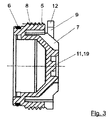
ピニオン1は、位置決め軸受3によって、ギヤハウジング2内に取り付けられている。ピニオンは、公知の態様で、回転運動を直線運動に変換するように、ハンドル(不図示)とギヤラック(同様に不図示)とに接続されている。ピニオンハブ上に螺合されたナット4が、ピニオン1を位置決め軸受3のインナーリングに固定するように作用する。
The
本発明による固定ネジ5は、中空ネジとしてプラスチック材料体からなり、位置決め軸受3のアウターリングを固定するために設けられている。
The
例えば他の非金属、焼結部材、ハイブリッド要素、といった他の材料が、本発明の枠内で、プラスチック材料の代わりに採用可能である。 Other materials such as other non-metals, sintered members, hybrid elements, etc. can be used in place of plastic materials within the framework of the present invention.
固定ネジ5のリング溝内のシールリング6が、シール機能を担っている。
The
固定ネジ5が、プラスチック材料の射出成形部品として製造される場合、シールリング6は、多成分要素の射出成形部品の場合、射出成形工程で固定ネジのプラスチック材料体に対してシリコンのようなソフト(柔軟)材料として固定的に結合され得る。このタイプの応用の利点は、製造及び組立がより簡易であることである。
When the
固定ネジ5の外側ネジ部8は、ギヤハウジング2の内側ネジ部と相互作用する。組立中、固定ネジ5は、所定のトルクで、ストッパまで締め付けられる。固定ネジ5を締め付けるために、前記ネジには幾つかのキャリヤ部7が設けられており、キャリヤ部7は、リブ形状に径方向に伸びている(特に、図2及び図4参照)。
The
当該目的のためには、いわゆる「浮遊」ネジ接続を提供することも可能である。それは、回転角度位置に依存した、あるいは、挿入深さに依存した、あるいは、締め付けストロークに依存した、固定ネジ5の締め付けによって特徴付けられる。
For this purpose it is also possible to provide so-called “floating” screw connections. It is characterized by tightening of the
ピニオン1と位置決め軸受3とによって生成される軸方向力は、遊びの無い態様で吸収されなければならない。当該力は、自己係止する固定ネジの外側ネジ部8によって、ギヤハウジング2内に導入される。
The axial force generated by the
当該ネジ固定手段は、径方向の再調整ラッチ機構からなる。この目的のため、固定ネジ5には、その周上において、幾つかのラチェットレバー9が設けられている。当該ラチェットレバー9は、各々その一端の領域において径方向スポーク10によって固定ネジの中央片11に接続されている。径方向スポーク10は、リブ形状のキャリヤ部7の一部であり得る。当該実施の形態では、4つのラチェットレバー9が、周上に分布配置されている。もっとも、他の数も、本発明の枠内において可能である。
The screw fixing means includes a radial readjustment latch mechanism. For this purpose, the
ラチェットレバー9には、スポーク10から離れた側のその自由端において、ラッチ突
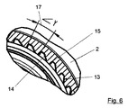
部12が設けられている。ラチェットレバー9のラッチ突部12は、ギヤハウジング2の歯付き形状部13にラッチ(係止)する(特に、図6の歯付き形状部の拡大図参照)。ラッチ突部12のギヤハウジング2の歯付き形状部13へのラッチ(係止)の結果、固定ネジ5の独立した緩みが防止される。
The
固定ネジ5がギヤハウジング2内に締め付けられる時、ラチェットレバー9は、ギヤハウジング2の傾斜部18によって径方向に見て偏向(変形)されて、所定のトルクが到達される時、歯付き形状部13の歯のギャップ14内にスナップインする。固定ネジ5の緩みは、歯付き形状部13の鋸歯状の輪郭によって防止される。ラチェットレバー9は、この目的のため、歯付き形状部13の歯のギャップ14内の当接面15にて支持される。
When the
径方向に偏向するラチェットレバー9の代わりに、それらは、必要に応じて、軸方向にも偏向され得て、対応する態様で、ハウジングの孔内の歯付き形状部の歯のギャップ内にラッチ(係合)し得る。
Instead of the radially deflecting
ここにおいても、逆の原理ないし逆の解決法が可能である。それによれば、孔2a内に配置されるラチェットレバーが、対応して、固定ネジ5の歯付き形状部内に軸方向にラッチ(係止)する。
Again, the opposite principle or the opposite solution is possible. According to this, the ratchet lever arranged in the
組立の際の回転角度に依存しないプラスチック材料ネジ5の締め付けを実現するために、ラチェットレバーの角度ピッチ16は、非対称に実現されている(図4参照)。ギヤハウジング2の歯付き形状部13は、対応して、できるだけ小さい角度ピッチ17で実現されている。この態様では、少なくとも2つのラッチ突部12の確実なラッチインが、回転角度に依存しないで、常に保証される。非対称性は、バーニア効果のために、増大される分解能、ないし、より大きなラッチの信頼性を導く。
In order to realize tightening of the
非対称なラチェットレバーの角度ピッチ16というのは、ラチェットレバーが全周に亘って均一分布に配置されていないことを意味する。従って、例えば4つのラチェットレバーの場合、正確な90°が4回の代わりに、異なる角度ピッチ及び異なる長さが提供され得る。個々の歯ギャップ14間(図6参照)で例えば15°という小さい角度ピッチ17が選択されるなら、非対称なラチェットレバーの角度ピッチ16の結果として、約4°毎の確実なラッチインが常に可能である(実際の実例に関する)。
The
プラスチック材料から実現される固定ネジ5は、例えば、繊維補強された熱可塑性材料からも、射出成形部品として実現される。それは、耐熱性能によって特徴付けられる。プラスチック材料体の膨張性能は、温度変化の際、当該材料と繊維アライメントとによって決定される。この目的のため、繊維は、それらがより大きな膨張の方向に伸びるように配置される。
The fixing
可能性ある長い曲げ長さの結果、低い延性降伏を有する高強度プラスチック製のラチェットレバー9を使用することが可能である。
As a result of the possible long bending length, it is possible to use a
端面上の中央射出点19に対する、キャリヤ部7とスポーク10の星形配置は、射出工程中のプラスチック材料の最適な流れ特性を可能とし、収縮による空洞ないし空孔を回避する。固定ネジ5の締め付け時、組立ツールによるトルクの吸収に加えて、当該実施形態が更なる利点をもたらす。
The star arrangement of the
固定ネジ5のプラスチック材料体のネジ部は、メートル角度ネジ部として実現され得る。当該ネジ部のフランク直径は、小さいネジバックラッシュのみが存在するように、設計される。
The screw part of the plastic material body of the fixing
本発明の枠内で、例えば円錐ネジのような、他のネジ形態も可能である。 Other thread forms are also possible within the framework of the invention, for example conical threads.
ギヤハウジング2内の内側歯と歯付き形状部13とを、等しくキャスト仕上げすることが可能である。必要であれば、制御された態様でハウジング2内の歯付き形状部13を加工することで、小さい許容誤差が実現され得る。
It is possible to cast the inner teeth in the
1 ピニオン
2 ギヤハウジング
2a 孔
3 位置決め軸受(固定軸受)
4 ナット
5 固定ネジ
6 シールリング
7 キャリヤ部
8 外側ネジ部
9 ラチェットレバー
10 スポーク
11 中央片
12 ラッチ突部
13 歯付き形状部
14 歯ギャップ
15 当接面
16 ラチェットレバーの角度ピッチ
17 角度ピッチ
18 傾斜部
19 射出点
1
4
Claims (14)
当該装置は、ハウジング(2)の孔(2a)内に挿入される固定要素を有し、
前記固定要素(5)は、少なくとも1つのラチェットレバー(9)が設けられていて、前記少なくとも1つのラチェットレバー(9)は、当該ラチェットレバーの自由端上に配置されたラッチ突部(12)によって、ハウジング(2)の孔(2a)内の歯付き形状部(13)の歯のギャップ(14)にラッチするか、
または、少なくとも1つのラチェットレバーが、ラッチ突部を有していて、孔(2a)内に配置されていて、当該ラッチ突部が固定要素(5)の歯付き形状部の歯のギャップにラッチし、
前記固定要素(5)は、外側ネジ部(8)によってハウジング(2)の孔(2a)の内側ネジ部に接続される固定ネジとして実現されており、
前記固定要素(5)のリング溝内に、前記固定要素(5)と前記ハウジング(2)との間のシール機能を担うシールリング(6)が配置されている
ことを特徴とする装置。 A device for fixing the unit in the housing (2), in particular a device for fixing the positioning bearing (3) of the pinion (1) of the steering gear of a motor vehicle,
The device has a fixing element inserted into the hole (2a) of the housing (2),
The fixing element (5) is provided with at least one ratchet lever (9), the at least one ratchet lever (9) being a latch projection (12) arranged on the free end of the ratchet lever. Latch into the tooth gap (14) of the toothed profile (13) in the hole (2a) of the housing (2),
Alternatively, at least one ratchet lever has a latching projection and is arranged in the hole (2a), and the latching projection latches in the tooth gap of the toothed shape of the fixing element (5) And
The fixing element (5) is realized as a fixing screw connected to the inner screw part of the hole (2a) of the housing (2) by the outer screw part (8),
A seal ring (6) for performing a sealing function between the fixing element (5) and the housing (2) is disposed in a ring groove of the fixing element (5). Device to do.
前記ラチェットレバー(9)は、各々、当該ラチェットレバーの自由端上に配置されたラッチ突部(12)によって、ハウジング(2)の歯付き形状部(13)の歯のギャップ(14)にラッチする
ことを特徴とする請求項1に記載の装置。 The fixing screw as the fixing element (5 ) is provided with a ratchet lever (9) distributed on the circumference thereof,
The ratchet levers (9) are each latched in the tooth gap (14) of the toothed profile (13) of the housing (2) by a latching projection (12) arranged on the free end of the ratchet lever. The apparatus according to claim 1, wherein:
ことを特徴とする請求項2に記載の装置。 Device according to claim 2, characterized in that the fixing screw (5) is realized as a hollow screw.
ことを特徴とする請求項2または3に記載の装置。 4. The device according to claim 2, wherein at least four ratchet levers (9) are distributed over the entire circumference of the fixing screw (5).
ことを特徴とする請求項4に記載の装置。 5. A device according to claim 4, characterized in that the ratchet lever (9) is distributed with an asymmetric angular pitch over the entire circumference of the fixing screw (5).
ことを特徴とする請求項5に記載の装置。 The angular pitch (17) of the toothed portion (13) of the housing (2) is clearly realized at a smaller angular pitch than the angular pitch (16) of the ratchet lever (9). The apparatus according to claim 5.
ことを特徴とする請求項1乃至6のいずれかに記載の装置。 7. The device according to claim 1, wherein the fixing element (5) is provided with several radially extending rib-shaped carrier parts (7).
ことを特徴とする請求項1乃至7のいずれかに記載の装置。 2. The fixing element (5) is realized as a plastic material body, in particular a fiber-reinforced thermoplastic material body, which is manufactured as an injection-molded part or a multi-component part. 8. The apparatus according to any one of 7.
ことを特徴とする請求項8に記載の装置。 9. The device of claim 8, wherein the fiber alignment within the thermoplastic material extends in the direction of greater expansion.
ことを特徴とする請求項8または9に記載の装置。 10. Device according to claim 8 or 9, characterized in that the plastic material body is provided with a central injection point (19).
ことを特徴とする請求項1乃至10のいずれかに記載の装置。 11. The latch protrusion (12) of the ratchet lever (9) is supported on the contact surface (15) of the housing (2), respectively. apparatus.
ことを特徴とする請求項2乃至11のいずれかに記載の装置。 12. The device according to claim 2, wherein the outer screw part (8) of the fixing screw (5) is realized as a conical screw part.
前記シールリング(6)が、射出成形工程でプラスチック材料体に対してソフト材料として固定的に結合される
ことを特徴とする請求項8に記載の装置。 The plastic material body is realized as a multi-component injection molded part,
9. Device according to claim 8, characterized in that the seal ring (6) is fixedly connected as a soft material to the plastic material body in an injection molding process.
Applications Claiming Priority (3)
| Application Number | Priority Date | Filing Date | Title |
|---|---|---|---|
| DE102011051961A DE102011051961A1 (en) | 2011-07-20 | 2011-07-20 | Device for securing a unit |
| DE102011051961.0 | 2011-07-20 | ||
| PCT/EP2012/063571 WO2013010873A1 (en) | 2011-07-20 | 2012-07-11 | Device for positional securing of a unit |
Publications (3)
| Publication Number | Publication Date |
|---|---|
| JP2014521042A JP2014521042A (en) | 2014-08-25 |
| JP2014521042A5 JP2014521042A5 (en) | 2015-08-27 |
| JP6017556B2 true JP6017556B2 (en) | 2016-11-02 |
Family
ID=46508059
Family Applications (1)
| Application Number | Title | Priority Date | Filing Date |
|---|---|---|---|
| JP2014520609A Expired - Fee Related JP6017556B2 (en) | 2011-07-20 | 2012-07-11 | Device for fixing the position of the unit |
Country Status (7)
| Country | Link |
|---|---|
| US (1) | US9086090B2 (en) |
| EP (1) | EP2734742B1 (en) |
| JP (1) | JP6017556B2 (en) |
| CN (1) | CN103688067B (en) |
| DE (1) | DE102011051961A1 (en) |
| HU (1) | HUE031732T2 (en) |
| WO (1) | WO2013010873A1 (en) |
Families Citing this family (11)
| Publication number | Priority date | Publication date | Assignee | Title |
|---|---|---|---|---|
| KR102096989B1 (en) * | 2013-11-04 | 2020-04-03 | 현대모비스 주식회사 | Support yoke clearance compensator of vehicle |
| US9879771B2 (en) * | 2015-03-27 | 2018-01-30 | Amarillo Gear Company Llc | Dry well shaft assembly |
| PT3298293T (en) * | 2015-05-22 | 2019-09-30 | Timken Co | Bearing package and installation tool |
| EP3365960A4 (en) | 2015-10-22 | 2019-06-19 | Nidec Motor Corporation | Electric motor |
| DE102015118887A1 (en) | 2015-11-04 | 2017-05-04 | Getrag Getriebe- Und Zahnradfabrik Hermann Hagenmeyer Gmbh & Cie Kg | Axial securing arrangement and axial securing method |
| CN106122237A (en) * | 2016-08-23 | 2016-11-16 | 瑞安市威孚标准件有限公司 | Self-locking screw |
| DE102018104608A1 (en) * | 2018-02-28 | 2019-08-29 | Trw Automotive Gmbh | Steering system shaft bearing assembly, steering system and method of making a steering system |
| DE102019213117A1 (en) * | 2019-08-30 | 2021-03-04 | Zf Friedrichshafen Ag | Securing device for a screw connection of a nut on a shaft |
| CN110513396B (en) * | 2019-09-04 | 2020-11-17 | 安徽省含山县林头振皖铸造厂 | Insulation type sealing end cover of motor rotating shaft bearing |
| CN112594286A (en) * | 2020-11-30 | 2021-04-02 | 河南航天精工制造有限公司 | Self-locking threaded sleeve |
| CN113944680B (en) * | 2021-10-18 | 2022-08-05 | 北京微纳星空科技有限公司 | Ratchet locking mechanism |
Family Cites Families (32)
| Publication number | Priority date | Publication date | Assignee | Title |
|---|---|---|---|---|
| US3650040A (en) * | 1969-08-28 | 1972-03-21 | Louis D Statham | Film dryer |
| DE2741904A1 (en) * | 1977-09-17 | 1979-03-29 | Klaus Boetzkes | Bunghole seal for beer cask - has threaded plastics insert engaged by dogs at end of bung |
| AU550194B2 (en) * | 1981-12-17 | 1986-03-06 | Bishop Steering Technology Limited | Rack and pinion steering gear |
| US4403933A (en) * | 1982-04-14 | 1983-09-13 | Fischer & Porter Company | Apparatus for injection-molding a liner onto a metal spool |
| US4717183A (en) * | 1982-07-07 | 1988-01-05 | Vetco Offshore Industries, Inc. | Conical thread configuration for rapid make-up connection |
| US4742883A (en) * | 1986-09-29 | 1988-05-10 | Ford Motor Company | Pinion ball bearings with preload adjustment for power rack and pinion steering gears |
| DE3935753A1 (en) * | 1988-11-12 | 1990-05-17 | Volkswagen Ag | Locking device for set screw, e.g. of fluid control device - is pretensioned latching organ on head of set screw engaging wall of threaded bore |
| US5234259A (en) * | 1990-09-07 | 1993-08-10 | Bridgestone Corporation | Resin wheel with more than two independently molded parts |
| SE504338C2 (en) * | 1994-06-07 | 1997-01-13 | Sandvik Ab | Cutting plate |
| SE509218C2 (en) * | 1994-08-29 | 1998-12-21 | Sandvik Ab | shaft Tools |
| JPH08145038A (en) * | 1994-11-24 | 1996-06-04 | Koizumi Sangyo Kk | Nut with seal washer |
| US5482132A (en) * | 1995-05-26 | 1996-01-09 | Birsching; Joel E. | Pinion head for power steering gear |
| AT403402B (en) * | 1995-11-06 | 1998-02-25 | Mark Rudolf | FASTENING ELEMENT |
| US5713706A (en) * | 1995-12-19 | 1998-02-03 | Shur-Lok Corporation | Plastic composite fastener for self-cutting and frictional welding |
| US5690143A (en) * | 1996-04-08 | 1997-11-25 | General Motors Corporation | Valve for power steering gear |
| WO2000073672A1 (en) * | 1999-05-28 | 2000-12-07 | The Aim Group, Llc | Locking nut, bolt and clip systems and assemblies |
| JP2003226246A (en) * | 2002-02-06 | 2003-08-12 | Koyo Seiko Co Ltd | Rack pinion type steering device |
| FR2853383B1 (en) * | 2003-04-07 | 2005-05-27 | Koyo Steering Europe Kse | DEVICE FOR RETRACTING THE RADIAL CLEARANCE OF A RATCHET PUSH-BUTTON |
| EP1489263B1 (en) * | 2003-06-19 | 2007-02-14 | ABB Turbo Systems AG | Turbocharger shaft-hub connection |
| US20050220569A1 (en) * | 2004-04-01 | 2005-10-06 | Joseph Dryer | Latching quick-connect connector |
| DE102004021484B4 (en) * | 2004-04-30 | 2018-11-29 | Böllhoff Verbindungstechnik GmbH | Method for producing a connection arrangement |
| WO2006014517A2 (en) * | 2004-07-07 | 2006-02-09 | Pyrotek Inc. | Molten metal pump |
| DE202005010873U1 (en) * | 2005-07-11 | 2005-09-22 | Böllhoff Verbindungstechnik GmbH | Tolerance equalizing unit for automatic equalizing of tolerances in the distance between two structural components and is cost effective to produce |
| JPWO2007013173A1 (en) * | 2005-07-29 | 2009-02-05 | 株式会社ジェイテクト | Method and structure for preventing screw loosening and method for manufacturing male screw |
| US20080044659A1 (en) * | 2005-12-15 | 2008-02-21 | Polystrand, Inc. | Composite laminate and method of manufacture |
| CN201031869Y (en) * | 2007-03-21 | 2008-03-05 | 张平 | Ratchet type anti-theft nut |
| WO2009001421A1 (en) * | 2007-06-25 | 2008-12-31 | Miraial Co., Ltd. | Mechanism for preventing loosening of bolt |
| JP5147066B2 (en) * | 2008-12-03 | 2013-02-20 | 内山工業株式会社 | Sealing structure |
| GB2485949A (en) * | 2009-09-25 | 2012-05-30 | Mclaren Performance Technologies Inc | Staked nut and flange for gear support |
| DE102010008404A1 (en) * | 2010-02-09 | 2011-08-11 | MAHLE International GmbH, 70376 | captive |
| DE102011051960A1 (en) * | 2011-07-20 | 2013-01-24 | Zf Lenksysteme Gmbh | Device for releasing a locking screw for a unit in a housing |
| US9010208B2 (en) * | 2012-07-13 | 2015-04-21 | Trw Automotive U.S. Llc | Yoke assembly for a rack and pinion steering gear and method for producing the same |
-
2011
- 2011-07-20 DE DE102011051961A patent/DE102011051961A1/en not_active Withdrawn
-
2012
- 2012-07-11 EP EP12734942.1A patent/EP2734742B1/en active Active
- 2012-07-11 JP JP2014520609A patent/JP6017556B2/en not_active Expired - Fee Related
- 2012-07-11 US US14/128,896 patent/US9086090B2/en active Active
- 2012-07-11 WO PCT/EP2012/063571 patent/WO2013010873A1/en active Application Filing
- 2012-07-11 CN CN201280035421.7A patent/CN103688067B/en active Active
- 2012-07-11 HU HUE12734942A patent/HUE031732T2/en unknown
Also Published As
| Publication number | Publication date |
|---|---|
| US9086090B2 (en) | 2015-07-21 |
| CN103688067B (en) | 2016-01-20 |
| WO2013010873A1 (en) | 2013-01-24 |
| US20140126976A1 (en) | 2014-05-08 |
| JP2014521042A (en) | 2014-08-25 |
| HUE031732T2 (en) | 2017-07-28 |
| EP2734742A1 (en) | 2014-05-28 |
| DE102011051961A1 (en) | 2013-01-24 |
| EP2734742B1 (en) | 2016-08-17 |
| CN103688067A (en) | 2014-03-26 |
Similar Documents
| Publication | Publication Date | Title |
|---|---|---|
| JP6017556B2 (en) | Device for fixing the position of the unit | |
| JP5869120B2 (en) | Device for removing the clamping screw for the unit in the housing | |
| CN109751372B (en) | Wedge adjuster plug | |
| JP2013520626A (en) | Helical gear device for automobile steering system | |
| JP2010270887A (en) | Electric actuator | |
| US20130133472A1 (en) | Motor vehicle pedal coupling apparatus and method | |
| KR20190110465A (en) | Spindle drive, method for producing a spindle drive and comfort drive | |
| JP2014521042A5 (en) | ||
| US9958050B2 (en) | Belt pulley and gear nut with such a belt pulley | |
| JP2013522114A (en) | Servo steering device | |
| KR19990088638A (en) | Worm gear unit | |
| EP3018385B1 (en) | Ball screw | |
| US11225283B2 (en) | Worm gear for a worm gear mechanism of a motor vehicle steering system made from fibre reinforced plastic with a targeted orientation of the fibres | |
| JP6938503B2 (en) | How to produce wiper motors and wiper motors | |
| JP3174891U (en) | Electric linear actuator | |
| JPWO2018079300A1 (en) | Imaging device | |
| CN112105544B (en) | Steering gear and method for producing a steering gear | |
| CN111788400A (en) | Steering system shaft bearing assembly, steering system and method for producing a steering system | |
| KR20240016882A (en) | Multi-component gear wheel for a gear assembly of a brake actuator, brake actuator having such a multi-component gear wheel, and method for producing such a multi-component wheel | |
| US20240093774A1 (en) | Gear | |
| US7649287B2 (en) | Motor fastening mechanism and cam device | |
| JP5022254B2 (en) | Axis stop structure for machine parts | |
| WO2022269986A1 (en) | Steering device | |
| CN113324013A (en) | Transmission housing unit and transmission unit | |
| JP2015075200A (en) | Linear actuator |
Legal Events
| Date | Code | Title | Description |
|---|---|---|---|
| A521 | Request for written amendment filed |
Free format text: JAPANESE INTERMEDIATE CODE: A523 Effective date: 20150706 |
|
| A621 | Written request for application examination |
Free format text: JAPANESE INTERMEDIATE CODE: A621 Effective date: 20150706 |
|
| A977 | Report on retrieval |
Free format text: JAPANESE INTERMEDIATE CODE: A971007 Effective date: 20160426 |
|
| A131 | Notification of reasons for refusal |
Free format text: JAPANESE INTERMEDIATE CODE: A131 Effective date: 20160506 |
|
| A521 | Request for written amendment filed |
Free format text: JAPANESE INTERMEDIATE CODE: A523 Effective date: 20160804 |
|
| RD03 | Notification of appointment of power of attorney |
Free format text: JAPANESE INTERMEDIATE CODE: A7423 Effective date: 20160823 |
|
| TRDD | Decision of grant or rejection written | ||
| A01 | Written decision to grant a patent or to grant a registration (utility model) |
Free format text: JAPANESE INTERMEDIATE CODE: A01 Effective date: 20160830 |
|
| A61 | First payment of annual fees (during grant procedure) |
Free format text: JAPANESE INTERMEDIATE CODE: A61 Effective date: 20160928 |
|
| R150 | Certificate of patent or registration of utility model |
Ref document number: 6017556 Country of ref document: JP Free format text: JAPANESE INTERMEDIATE CODE: R150 |
|
| R250 | Receipt of annual fees |
Free format text: JAPANESE INTERMEDIATE CODE: R250 |
|
| R250 | Receipt of annual fees |
Free format text: JAPANESE INTERMEDIATE CODE: R250 |
|
| R250 | Receipt of annual fees |
Free format text: JAPANESE INTERMEDIATE CODE: R250 |
|
| LAPS | Cancellation because of no payment of annual fees |