JP6017445B2 - Fiber structure for parts made of composite material having one or more arcuate shapes - Google Patents
Fiber structure for parts made of composite material having one or more arcuate shapes Download PDFInfo
- Publication number
- JP6017445B2 JP6017445B2 JP2013543854A JP2013543854A JP6017445B2 JP 6017445 B2 JP6017445 B2 JP 6017445B2 JP 2013543854 A JP2013543854 A JP 2013543854A JP 2013543854 A JP2013543854 A JP 2013543854A JP 6017445 B2 JP6017445 B2 JP 6017445B2
- Authority
- JP
- Japan
- Prior art keywords
- warp
- arcuate
- weft
- fiber
- arcuate portion
- Prior art date
- Legal status (The legal status is an assumption and is not a legal conclusion. Google has not performed a legal analysis and makes no representation as to the accuracy of the status listed.)
- Active
Links
- 239000000835 fiber Substances 0.000 title claims description 88
- 239000002131 composite material Substances 0.000 title claims description 21
- 239000011159 matrix material Substances 0.000 claims description 14
- 230000002787 reinforcement Effects 0.000 claims description 13
- 239000000725 suspension Substances 0.000 claims description 11
- 239000012783 reinforcing fiber Substances 0.000 claims description 2
- 239000002759 woven fabric Substances 0.000 claims 1
- 229920005989 resin Polymers 0.000 description 14
- 239000011347 resin Substances 0.000 description 14
- 238000009941 weaving Methods 0.000 description 13
- 238000000280 densification Methods 0.000 description 6
- 238000000034 method Methods 0.000 description 6
- 239000002243 precursor Substances 0.000 description 6
- OKTJSMMVPCPJKN-UHFFFAOYSA-N Carbon Chemical compound [C] OKTJSMMVPCPJKN-UHFFFAOYSA-N 0.000 description 5
- 229910052799 carbon Inorganic materials 0.000 description 5
- 239000000919 ceramic Substances 0.000 description 5
- 238000010438 heat treatment Methods 0.000 description 5
- 238000005192 partition Methods 0.000 description 5
- 239000007788 liquid Substances 0.000 description 4
- 239000003822 epoxy resin Substances 0.000 description 3
- 239000012705 liquid precursor Substances 0.000 description 3
- 239000000463 material Substances 0.000 description 3
- 229910052751 metal Inorganic materials 0.000 description 3
- 239000002184 metal Substances 0.000 description 3
- 229920000647 polyepoxide Polymers 0.000 description 3
- 238000005516 engineering process Methods 0.000 description 2
- LNEPOXFFQSENCJ-UHFFFAOYSA-N haloperidol Chemical compound C1CC(O)(C=2C=CC(Cl)=CC=2)CCN1CCCC(=O)C1=CC=C(F)C=C1 LNEPOXFFQSENCJ-UHFFFAOYSA-N 0.000 description 2
- 238000005470 impregnation Methods 0.000 description 2
- 229920003257 polycarbosilane Polymers 0.000 description 2
- 229920000642 polymer Polymers 0.000 description 2
- 229920001709 polysilazane Polymers 0.000 description 2
- HBMJWWWQQXIZIP-UHFFFAOYSA-N silicon carbide Chemical compound [Si+]#[C-] HBMJWWWQQXIZIP-UHFFFAOYSA-N 0.000 description 2
- 229910010271 silicon carbide Inorganic materials 0.000 description 2
- 239000002904 solvent Substances 0.000 description 2
- KXGFMDJXCMQABM-UHFFFAOYSA-N 2-methoxy-6-methylphenol Chemical compound [CH]OC1=CC=CC([CH])=C1O KXGFMDJXCMQABM-UHFFFAOYSA-N 0.000 description 1
- MBYPPIJDMYFBRF-UHFFFAOYSA-N CCCCCCCCCC[IH]C1=CN1 Chemical compound CCCCCCCCCC[IH]C1=CN1 MBYPPIJDMYFBRF-UHFFFAOYSA-N 0.000 description 1
- RTAQQCXQSZGOHL-UHFFFAOYSA-N Titanium Chemical compound [Ti] RTAQQCXQSZGOHL-UHFFFAOYSA-N 0.000 description 1
- 239000000853 adhesive Substances 0.000 description 1
- 230000001070 adhesive effect Effects 0.000 description 1
- 239000000571 coke Substances 0.000 description 1
- 238000010276 construction Methods 0.000 description 1
- 238000010586 diagram Methods 0.000 description 1
- 238000002347 injection Methods 0.000 description 1
- 239000007924 injection Substances 0.000 description 1
- 238000003780 insertion Methods 0.000 description 1
- 230000037431 insertion Effects 0.000 description 1
- 238000004519 manufacturing process Methods 0.000 description 1
- 150000002739 metals Chemical class 0.000 description 1
- 239000000203 mixture Substances 0.000 description 1
- 229920001568 phenolic resin Polymers 0.000 description 1
- 239000005011 phenolic resin Substances 0.000 description 1
- 238000006116 polymerization reaction Methods 0.000 description 1
- 239000011148 porous material Substances 0.000 description 1
- 238000000197 pyrolysis Methods 0.000 description 1
- 239000012744 reinforcing agent Substances 0.000 description 1
- 230000000630 rising effect Effects 0.000 description 1
- 238000009958 sewing Methods 0.000 description 1
- 238000007493 shaping process Methods 0.000 description 1
- 230000000930 thermomechanical effect Effects 0.000 description 1
- 229920001187 thermosetting polymer Polymers 0.000 description 1
- 239000010936 titanium Substances 0.000 description 1
- 229910052719 titanium Inorganic materials 0.000 description 1
- 238000001721 transfer moulding Methods 0.000 description 1
- XLYOFNOQVPJJNP-UHFFFAOYSA-N water Substances O XLYOFNOQVPJJNP-UHFFFAOYSA-N 0.000 description 1
Images


Classifications
-
- D—TEXTILES; PAPER
- D03—WEAVING
- D03D—WOVEN FABRICS; METHODS OF WEAVING; LOOMS
- D03D13/00—Woven fabrics characterised by the special disposition of the warp or weft threads, e.g. with curved weft threads, with discontinuous warp threads, with diagonal warp or weft
- D03D13/004—Woven fabrics characterised by the special disposition of the warp or weft threads, e.g. with curved weft threads, with discontinuous warp threads, with diagonal warp or weft with weave pattern being non-standard or providing special effects
-
- B—PERFORMING OPERATIONS; TRANSPORTING
- B29—WORKING OF PLASTICS; WORKING OF SUBSTANCES IN A PLASTIC STATE IN GENERAL
- B29B—PREPARATION OR PRETREATMENT OF THE MATERIAL TO BE SHAPED; MAKING GRANULES OR PREFORMS; RECOVERY OF PLASTICS OR OTHER CONSTITUENTS OF WASTE MATERIAL CONTAINING PLASTICS
- B29B11/00—Making preforms
- B29B11/14—Making preforms characterised by structure or composition
- B29B11/16—Making preforms characterised by structure or composition comprising fillers or reinforcement
-
- B—PERFORMING OPERATIONS; TRANSPORTING
- B29—WORKING OF PLASTICS; WORKING OF SUBSTANCES IN A PLASTIC STATE IN GENERAL
- B29C—SHAPING OR JOINING OF PLASTICS; SHAPING OF MATERIAL IN A PLASTIC STATE, NOT OTHERWISE PROVIDED FOR; AFTER-TREATMENT OF THE SHAPED PRODUCTS, e.g. REPAIRING
- B29C70/00—Shaping composites, i.e. plastics material comprising reinforcements, fillers or preformed parts, e.g. inserts
- B29C70/04—Shaping composites, i.e. plastics material comprising reinforcements, fillers or preformed parts, e.g. inserts comprising reinforcements only, e.g. self-reinforcing plastics
- B29C70/06—Fibrous reinforcements only
- B29C70/10—Fibrous reinforcements only characterised by the structure of fibrous reinforcements, e.g. hollow fibres
- B29C70/16—Fibrous reinforcements only characterised by the structure of fibrous reinforcements, e.g. hollow fibres using fibres of substantial or continuous length
- B29C70/22—Fibrous reinforcements only characterised by the structure of fibrous reinforcements, e.g. hollow fibres using fibres of substantial or continuous length oriented in at least two directions forming a two dimensional structure
- B29C70/222—Fibrous reinforcements only characterised by the structure of fibrous reinforcements, e.g. hollow fibres using fibres of substantial or continuous length oriented in at least two directions forming a two dimensional structure the structure being shaped to form a three dimensional configuration
-
- B—PERFORMING OPERATIONS; TRANSPORTING
- B64—AIRCRAFT; AVIATION; COSMONAUTICS
- B64D—EQUIPMENT FOR FITTING IN OR TO AIRCRAFT; FLIGHT SUITS; PARACHUTES; ARRANGEMENTS OR MOUNTING OF POWER PLANTS OR PROPULSION TRANSMISSIONS IN AIRCRAFT
- B64D27/00—Arrangement or mounting of power plant in aircraft; Aircraft characterised thereby
-
- B64D27/40—
-
- D—TEXTILES; PAPER
- D03—WEAVING
- D03D—WOVEN FABRICS; METHODS OF WEAVING; LOOMS
- D03D1/00—Woven fabrics designed to make specified articles
-
- D—TEXTILES; PAPER
- D03—WEAVING
- D03D—WOVEN FABRICS; METHODS OF WEAVING; LOOMS
- D03D11/00—Double or multi-ply fabrics not otherwise provided for
- D03D11/02—Fabrics formed with pockets, tubes, loops, folds, tucks or flaps
-
- D—TEXTILES; PAPER
- D03—WEAVING
- D03D—WOVEN FABRICS; METHODS OF WEAVING; LOOMS
- D03D25/00—Woven fabrics not otherwise provided for
- D03D25/005—Three-dimensional woven fabrics
-
- F—MECHANICAL ENGINEERING; LIGHTING; HEATING; WEAPONS; BLASTING
- F01—MACHINES OR ENGINES IN GENERAL; ENGINE PLANTS IN GENERAL; STEAM ENGINES
- F01D—NON-POSITIVE DISPLACEMENT MACHINES OR ENGINES, e.g. STEAM TURBINES
- F01D25/00—Component parts, details, or accessories, not provided for in, or of interest apart from, other groups
- F01D25/24—Casings; Casing parts, e.g. diaphragms, casing fastenings
-
- D—TEXTILES; PAPER
- D10—INDEXING SCHEME ASSOCIATED WITH SUBLASSES OF SECTION D, RELATING TO TEXTILES
- D10B—INDEXING SCHEME ASSOCIATED WITH SUBLASSES OF SECTION D, RELATING TO TEXTILES
- D10B2505/00—Industrial
- D10B2505/02—Reinforcing materials; Prepregs
-
- F—MECHANICAL ENGINEERING; LIGHTING; HEATING; WEAPONS; BLASTING
- F05—INDEXING SCHEMES RELATING TO ENGINES OR PUMPS IN VARIOUS SUBCLASSES OF CLASSES F01-F04
- F05D—INDEXING SCHEME FOR ASPECTS RELATING TO NON-POSITIVE-DISPLACEMENT MACHINES OR ENGINES, GAS-TURBINES OR JET-PROPULSION PLANTS
- F05D2300/00—Materials; Properties thereof
- F05D2300/60—Properties or characteristics given to material by treatment or manufacturing
- F05D2300/603—Composites; e.g. fibre-reinforced
-
- Y—GENERAL TAGGING OF NEW TECHNOLOGICAL DEVELOPMENTS; GENERAL TAGGING OF CROSS-SECTIONAL TECHNOLOGIES SPANNING OVER SEVERAL SECTIONS OF THE IPC; TECHNICAL SUBJECTS COVERED BY FORMER USPC CROSS-REFERENCE ART COLLECTIONS [XRACs] AND DIGESTS
- Y02—TECHNOLOGIES OR APPLICATIONS FOR MITIGATION OR ADAPTATION AGAINST CLIMATE CHANGE
- Y02T—CLIMATE CHANGE MITIGATION TECHNOLOGIES RELATED TO TRANSPORTATION
- Y02T50/00—Aeronautics or air transport
- Y02T50/60—Efficient propulsion technologies, e.g. for aircraft
-
- Y—GENERAL TAGGING OF NEW TECHNOLOGICAL DEVELOPMENTS; GENERAL TAGGING OF CROSS-SECTIONAL TECHNOLOGIES SPANNING OVER SEVERAL SECTIONS OF THE IPC; TECHNICAL SUBJECTS COVERED BY FORMER USPC CROSS-REFERENCE ART COLLECTIONS [XRACs] AND DIGESTS
- Y10—TECHNICAL SUBJECTS COVERED BY FORMER USPC
- Y10T—TECHNICAL SUBJECTS COVERED BY FORMER US CLASSIFICATION
- Y10T428/00—Stock material or miscellaneous articles
- Y10T428/24—Structurally defined web or sheet [e.g., overall dimension, etc.]
- Y10T428/24479—Structurally defined web or sheet [e.g., overall dimension, etc.] including variation in thickness
- Y10T428/24612—Composite web or sheet
Description
本発明は、複合材料部品を作製すること、より詳細には、そのような部品用の繊維強化構造を作製することに関する。 The present invention relates to making composite parts, and more particularly to making fiber reinforced structures for such parts.
本発明の応用分野は、より詳細には、構造複合材料から部品、つまり、マトリックスで緻密化された繊維強化構造を有する部品を作製する分野である。複合材料は、もしそれらが金属からなるなら、同一部品が有する重量より軽い全体重量の部品を作製することを可能にする。 The field of application of the invention is more particularly the field of making parts from structural composites, ie parts having a fiber-reinforced structure densified with a matrix. Composite materials make it possible to make parts with an overall weight that is lighter than the weight of the same part if they are made of metal.
複合材料から作製された標準形状の部品は、一般的に、良好な構造特性および高強度を示し、特に、部品の繊維強化材は、通常単体として作製され、したがって、部品のいずれかの一部に作用する機械的な力が良好に分配されることを可能にするからである。 Standard shaped parts made from composite materials generally exhibit good structural properties and high strength, in particular, the fiber reinforcement of the part is usually made as a single piece, and thus is part of any of the parts This is because the mechanical force acting on the can be distributed well.
対照的に、形状がより複雑な複合材料部品、特に、全体として部品を支持するための1つ以上の要素を有する部品を作製する場合には、部品全体にわたって高い機械的強度を有することは一般的に可能ではない。 In contrast, when making composite parts that are more complex in shape, particularly those having one or more elements to support the part as a whole, it is common to have high mechanical strength throughout the part. Is not possible.
一例として、飛行機の翼にエンジンを取り付けるための1つ以上の懸垂ヨークを有する航空エンジンケーシングを作製するために複合材料を使用する場合には、懸垂ヨークにおける繊維強化材は、ケーシングシュラウドの繊維強化材とは独立して製造され、続いて、それに、例えば、縫製または接着剤によって加えられる。エンジン支持ヨークに作用する非常に大きな機械的応力(数千トン)のために、そのようなケーシング設計は、十分な機械的強度をもたらすことができない。したがって、その種の部品は、現在、金属から常に作製されており、したがって、比較的高い全体重量を示す。 As an example, if a composite material is used to make an aero engine casing having one or more suspension yokes for mounting the engine on an airplane wing, the fiber reinforcement in the suspension yoke is the fiber reinforcement of the casing shroud. Manufactured independently of the material and subsequently applied to it, for example, by sewing or adhesive. Due to the very large mechanical stress (several thousand tons) acting on the engine support yoke, such a casing design cannot provide sufficient mechanical strength. Therefore, such parts are now always made from metal and thus exhibit a relatively high overall weight.
必要な機械的性質をさらに有しながら、低減された全体重量を示す複雑な形状の部品を有することができることが望ましい。 It is desirable to be able to have complex shaped parts that exhibit reduced overall weight while still having the necessary mechanical properties.
上記の目的を達成するために、本発明は、マトリックスによって緻密化された繊維強化材を含む複合材料部品を提供し、部品は、弓形状の少なくとも1つの要素を有し、前記強化材は、複合材料部品用の強化繊維構造によって構成されており、前記構造は、前記構造の2つの面間に隣接して配置された横糸の複数の層と縦糸の複数の層との間の多層織りによって単体として織られており、複合材料部品は、繊維構造が、前記繊維構造の面のうちの1つに延在する少なくとも1つの弓状部を有し、弓状部は、構造の面のうちの1つの上に存在する少なくとも2つの隣接する縦糸層と連続する少なくともいくつかの縦糸を含み、前記弓状部の縦糸は、前記構造の少なくとも2つの基礎となる縦糸層の縦糸より長く、前記弓状部の前記縦糸は、繊維構造の他の縦糸に結ばれていないことを特徴とする。 To achieve the above objective, the present invention provides a composite part comprising a fiber reinforcement densified by a matrix, the part having at least one element in the shape of an arc, said reinforcement comprising: Constituted by a reinforcing fiber structure for composite parts, said structure being formed by a multi-layer weave between a plurality of layers of weft yarns and a plurality of layers of warp yarns arranged adjacent to each other between two faces of the structure Woven as a single piece, the composite material has at least one arcuate portion in which the fiber structure extends to one of the surfaces of the fiber structure, the arcuate portion of the surface of the structure Including at least some warp yarns continuous with at least two adjacent warp yarn layers present on one of the arches, wherein the warp yarns of the arcuate section are longer than the warp yarns of at least two underlying warp yarn layers of the structure, The warp of the arcuate part is a fiber Wherein the not connected to other warp concrete.
したがって、弓状部から形成された懸垂または取り付け要素を含む複合材料部品を形成することが可能である。弓状部は、繊維構造の残りと連続する縦糸から織られているので、部品の懸垂または取り付け要素に作用する力は、部品の全体構造によって吸収することができる。 Accordingly, it is possible to form a composite part that includes a suspension or attachment element formed from an arcuate portion. Since the arcuate part is woven from warps continuous with the rest of the fiber structure, forces acting on the suspension or attachment elements of the part can be absorbed by the overall structure of the part.
本発明の様々な実施形態では、繊維構造は、横糸方向に隣接して配置された複数の弓状部、および/または縦糸方向に互いにオフセットされた複数の弓状部を有し、これは、前記繊維構造の一方または両方の面に適用する。 In various embodiments of the present invention, the fibrous structure has a plurality of arcuate portions disposed adjacent to the weft direction and / or a plurality of arcuate portions offset from one another in the warp direction, Applies to one or both sides of the fiber structure.
本発明の特徴によれば、繊維構造は、縦糸方向に決定された長さにわたって延在し、横糸方向に決定された幅を有するストリップの形態であり、各弓状部は、繊維構造の長さ未満である縦糸方向の長さにわたって延在し、前記構造の幅未満である横糸方向の幅を有する。異なる実施形態では、弓状部は、繊維構造のストリップの幅に等しい横糸方向の幅を有してもよい。 According to a feature of the invention, the fiber structure is in the form of a strip extending over a length determined in the warp direction and having a width determined in the weft direction, each arcuate part being the length of the fiber structure Extending over a length in the warp direction that is less than the length and having a width in the weft direction that is less than the width of the structure. In different embodiments, the arcuate portion may have a width in the weft direction equal to the width of the strip of fiber structure.
本発明の態様では、各弓状部は、弓状部の下に位置する繊維構造の一部のスレッドカウントと実質的に同一の縦糸方向のスレッドカウントを有する。 In an aspect of the invention, each arcuate portion has a warp direction thread count that is substantially the same as the thread count of the portion of the fiber structure located below the arcuate portion.
本発明の他の態様では、各弓状部は、弓状部の下に位置する前記繊維構造の一部のスレッドカウント未満である縦糸方向のスレッドカウントを有する。 In another aspect of the invention, each arcuate portion has a warp direction thread count that is less than the thread count of a portion of the fibrous structure located below the arcuate portion.
本発明のさらに他の態様では、各弓状部は、弓状部の下に位置する繊維構造の一部の横糸の重量より大きい重量の横糸を含んでいてもよい。 In yet another aspect of the present invention, each arcuate portion may include a weft weight that is greater than the weight of the weft portion of the fibrous structure located below the arcuate portion.
本発明の複合材料部品は、特に、少なくとも1つの懸垂ヨークを有する航空エンジンケーシングを構成していてもよい。 The composite part according to the invention may in particular constitute an aero engine casing having at least one suspension yoke.
本発明は、また、本発明のエンジンケーシングが取り付けられたターボプロップを提供する。 The present invention also provides a turboprop fitted with the engine casing of the present invention.
本発明は、また、本発明の少なくとも1つのターボプロップが取り付けられた航空機を提供する。 The present invention also provides an aircraft fitted with at least one turboprop of the present invention.
本発明の他の特性および利点が、限定しない実施例として付与された特有の実施形態の次の説明から、および添付図面を参照して明らかとなる。 Other characteristics and advantages of the invention will become apparent from the following description of specific embodiments given as non-limiting examples and with reference to the accompanying drawings.
本発明は、繊維構造を、弓形状の少なくとも1つの要素を含む複合材料部品を製造するための繊維強化材またはプリフォームを構成用に適したものとすることに概して適用する。 The present invention applies generally to making the fiber structure suitable for construction of a fiber reinforcement or preform for producing a composite part comprising at least one element in the shape of an arc.
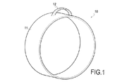
本発明によれば、弓形状の要素を形成する繊維構造の一部は、繊維構造の残りと一体的に作製されている。より正確には、および詳細に以下に説明されるように、弓形状の要素を形成する一部は、構造の残りと連続する縦糸から織られている。したがって、弓形状の要素に及ぼされる力は、複合材料部品用の強化剤を構成する繊維構造によって、全体として吸収することができる。図1は、エンジンが、飛行機の翼のパイロン(図1に示されていない)に取り付けられることを可能にするための懸垂ヨーク12を有するシュラウド11を形成する複合材料からなる航空エンジンのケーシング10を示す。
According to the invention, a part of the fiber structure forming the bow-shaped element is made integrally with the rest of the fiber structure. More precisely, and as will be described in detail below, the portion forming the arcuate element is woven from warp yarns continuous with the rest of the structure. Thus, the force exerted on the arcuate element can be absorbed as a whole by the fiber structure that constitutes the reinforcing agent for the composite part. FIG. 1 shows an
図2は、ケーシング10の繊維プリフォームを形成するための繊維ブランク100の非常に概略的な図である。
FIG. 2 is a very schematic view of a fiber blank 100 for forming a fiber preform of the
図2に概略的に示されるように、繊維ブランク100は、縦糸101の束または複数の層を構成するストランドを有するジャカード型の織機による公知の方法で行われる多層織りによって得られ、縦糸は、横糸102によって結ばれている。
As schematically shown in FIG. 2, the fiber blank 100 is obtained by multilayer weaving performed in a known manner by a jacquard type loom having a bundle of
示された例において、多層織りは、「インターロック」織りを備えた織りである。用語「インターロック」は、横糸の各層が縦糸の複数の層を結ぶ織りを表すために本明細書で使用されており、所定の横糸列のすべての糸が織り面で同じ動きを有する。 In the example shown, the multi-layer weave is a weave with an “interlock” weave. The term “interlock” is used herein to describe a weave where each layer of weft yarns connects multiple layers of warp yarns, and all yarns in a given weft row have the same movement on the weave surface.
特に、文献の国際公開第2006/136755号に記載されたものなどの他の公知のタイプの多層織りが使用されることができ、その内容は引用することによって本明細書に含めるものとする。 In particular, other known types of multi-layer weaves can be used, such as those described in the document WO 2006/136755, the contents of which are hereby incorporated by reference.
特有であるが、非排他的な方法で、本発明の繊維ブランクは、炭素、炭化ケイ素繊維などのセラミック、または実際にチタンなどの金属からなる繊維糸を使用することによって織られてもよい。 In a unique but non-exclusive manner, the fiber blanks of the present invention may be woven by using fiber yarns made of ceramics such as carbon, silicon carbide fibers, or indeed metals such as titanium.
図2に示されるように、繊維ブランク100は、方向Xに縦に延在するストリップ110の形態であり、ストリップは、一旦ブランクが成形され、ケーシング10のシュラウド11を形成するようにされ、繊維ブランク上に存在する懸垂ヨーク12を形成する弓状部120がある。
As shown in FIG. 2, the fiber blank 100 is in the form of a
弓状部120を含む一部100bの一方の側に位置する繊維ブランク100の一部100aおよび100cでは、縦糸の層はすべて、同じ長さの縦糸を含み、横糸は、縦糸の層がすべて結ばれているブランクの一部100aおよび100cにおいて構造を得るように、少なくとも縦糸の隣接した層と縦糸の各層を結ぶために使用される。
In the
一部100bでは、ストリップ110は、縦糸層の第1のグループ101aと縦糸層の第2のグループ101bとの間に形成された、結ばれていないゾーン111によって2つのサブストリップ110aおよび110bに分けられる。サブストリップ110aは、繊維ブランク100の1つの面、この例における上面上に存在する縦糸の第1の層から得られた少なくとも2つの隣接するまたは連続する縦糸層から構成されており、一方、サブストリップ110bは、サブストリップ110aの層の基礎となる縦糸層から構成されている。本発明によれば、サブストリップ110aの縦糸は、サブストリップ110bの基礎となる縦糸層の糸より長い。この長さの差は、サブストリップ110bの縦糸層の縦糸に適用される引き速度より速いサブストリップ110aの縦糸層の縦糸に引き速度を適用することによって得られてもよい。異なる実施では、サブストリップ110aの縦糸層の縦糸の長さは、サブストリップ110aの縦糸層の縦糸を引っ張ることによって、サブストリップ110bの縦糸の長さに対して大きくされてもよい。
In
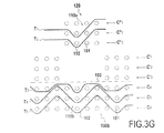
図3A〜図3Dは、ブランク100の一部100aまたは100cにおけるインターロック織りで多層織りを行う1つの手段を示す図であり、それらの図は、連続縦糸断面のそれぞれの拡大部分図である。この例において、ブランク100は、方向Xに延在する縦糸101の6つの層を含む。図3A〜図3Dでは、縦糸の6つの層C1〜C6は、横糸T1〜T5によって結ばれている。単純化の目的のために、縦糸の6つの層および横糸の5つの層のみが示され、当然、得られる繊維構造の幅および厚さの寸法に沿って延在し、その構造は、実際、いくつかの縦糸層および横糸層で、およびはるかに大きい層当たりいくつかの数の糸で作製されてもよい。
3A-3D are diagrams showing one means of performing multi-layer weaving with interlock weave in a
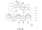
図3E〜図3Hは、弓状部120およびサブストリップ110bの両方を有するサブストリップ110aを含むブランク100の一部100bについての織りの連続縦糸断面におけるそれぞれの拡大部分図である。一部100bでは、ブランク100が、結ばれていないゾーン111を形成するサブストリップ110aおよび110b間の結ばれてない部分103を有するように、横糸T3は縦糸層C3およびC4を結ばない。図3E〜図3Hは、弓状部120の立ち上がり部に位置する連続織り面に相当する。
3E-3H are respective enlarged partial views in a woven continuous warp section for a
図3Eにおいて、層C”1、C”2、C”3は、弓状部120を形成する際に用いられる3つの縦糸層C1、C2およびC3において縦糸のそれぞれの割合に一致し、横糸T1およびT2によって互いに結ばれており、一方、層C’1、C’2およびC’3は、3つの縦糸層C1、C2およびC3の残りの縦糸に相当し、織られていない。3つの基礎となる縦糸層C4、C5およびC6は、横糸T3、T4およびT5によって結ばれている。
In FIG. 3E, the layers C ″ 1, C ″ 2, C ″ 3 correspond to the respective proportions of the warp yarns in the three warp layers C1, C2 and C3 used in forming the
図3F、図3Gおよび図3Hは、それぞれ、図3Eの織り面に続いて作製された3つの連続織り面を示す。図3E〜図3Hの織り面は、弓状部120の全長にわたって繰り返されている。
3F, 3G, and 3H each show three continuous woven surfaces made following the woven surface of FIG. 3E. The woven surfaces of FIGS. 3E-3H are repeated over the entire length of the
図3I〜図3Lは、一部100bを含むブランク100の織りの連続横糸断面のそれぞれの拡大部分図である。一部100bでは、2つの横糸層C”T1およびC”T2の横糸は、サブストリップ110aに属し、縦糸層C”1、C”2およびC”3の縦糸ch1、ch2およびch3で織られており(図3E〜図3H)、一方、サブストリップ110bの一部を形成する基礎となる横糸層CT3、CT4およびCT5の他の横糸は、縦糸層C4、C5およびC6の縦糸ch4、ch5およびch6で織られている(図3E〜図3H)。
FIGS. 3I to 3L are enlarged partial views of respective continuous weft cross sections of the weave of the blank 100 including the
図3I〜図3Lに示されるように、一部100bにおいて、層C”T1およびC”T2にそれぞれ存在する横糸T1およびT2の数は、層CT3、CT4およびCT5にそれぞれ存在する横糸T3、T4およびT5の数より大きい。これは、サブストリップ110bに対して、およびブランク100の残りに対してサブストリップ110aにおいて一定のスレッドカウントを維持する役目をし、つまり、縦糸方向の単位長さあたりの横糸の数は、2つのサブストリップ110aと110bとの間で一定であり、これは、サブストリップ110aで縦糸のより大きな長さにもかかわらず適用する。同じ数の横糸が、サブ ストリップ110aおよび110bに挿入されるなら、そのとき、サブストリップ110aにおいて縦糸方向の2つの隣接した横糸の間のピッチは、サブストリップ110bに挿入された 横糸より重い横糸を挿入することによって低減されてもよい。
As shown in FIGS. 3I-3L, in
サブストリップ110aのスレッドカウントは、また、サブストリップ110bより小さく(または緩く)てもよく、つまり、縦糸方向の単位長さあたりの横糸の数は、サブストリップ110bよりサブストリップ110aにおいてより少ない。
The thread count of the substrip 110a may also be smaller (or looser) than the
織りの最後に、不織の縦糸、つまり、この例において、層C’1、C’2およびC’3の縦糸(図3E〜図3H)、および不織の横糸、つまり、層C”1、C”2およびC”3の外側に位置する横糸T1およびT2の一部は、図2に示されるように、ブランク100を引き抜くために切り離され、それは、任意の成形前に多層織りから生じるブランクを示す。異なる実施形態では、弓状部は、また、その厚みを低減および/または横糸方向にその幅プロフィールを変更するために、例えば、水ジェットを使用して切断されてもよい。 At the end of weaving, a non-woven warp, i.e., in this example, the warp of layers C'1, C'2 and C'3 (Figs. 3E-3H), and the non-woven weft, i.e. layer C "1 , C ″ 2 and C ″ 3, a portion of the weft threads T1 and T2 are cut off to pull out the blank 100, as shown in FIG. 2, which results from the multi-layer weave before any forming In a different embodiment, the arcuate portion may also be cut using, for example, a water jet to reduce its thickness and / or change its width profile in the weft direction.
一部100bにおいてサブストリップ110aの縦糸の余分な長さ、およびサブストリップ110aおよび110bの間の織りの間に編成される結ばれていないゾーン111は、ともに弓状部120を形成することを可能にする。
The extra length of the warp of the substrip 110a in the
本発明の繊維構造の弓状部は、結ばれている複数の縦糸層から構成されている。基礎となるストリップの残りに対して、この一部は、つまり、構造がマトリックスで緻密化された後に、最終部品で保存される空洞を定義する。 The bow portion of the fiber structure of the present invention is composed of a plurality of warp layers that are tied together. For the rest of the underlying strip, this part defines the cavity that is preserved in the final part after the structure has been densified with a matrix.
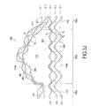
その後、繊維ブランクは、図1のケーシング10を形成するために緻密化される。この目的のために、図4に示されるように、繊維ブランク100は、マンドレル150のまわりに成形され、一例として、ブランク100の2つの自由端は、前記緻密化に先立ってともに縫われてもよく、または、それらは、端部が緻密化中にともに接合された状態で単に重ね合わされてもよい。これは、緻密化される準備ができた繊維プリフォーム130を生成する。弓状部120の内部形状に相当する挿入部160も、弓状部を緻密化中に形状を維持し、マトリックスが弓状部120とブランクの底のストリップとの間に存在する体積で形成されることを防ぐように設置されている。異なる実施形態では、繊維ブランクは、ケーシングの周囲の数倍に相当する長さを有し、弓状部は、最後のターンの間、または逆に初期のターンの間に、マンドレルに設置されたブランクの一部上に位置していてもよく、開口は、弓状部が次のターンを通り抜けることを可能にし、そのときブランクに設けられる。
The fiber blank is then densified to form the
繊維プリフォームの緻密化は、マトリックスを構成する材料を使用することによって、プリフォームの気孔の体積の全部または一部を充填することにある。 The densification of the fiber preform consists in filling all or part of the pore volume of the preform by using the material that makes up the matrix.
簡素化された構造を構成する複合材料のマトリックスは、液体技術を使用して公知の方法で得られてもよい。 The matrix of composite material that constitutes the simplified structure may be obtained in a known manner using liquid technology.
液体技術は、マトリックスの材料用の有機前駆体を含む液体組成物をプリフォームに含浸することにある。有機前駆体は、通常、樹脂などのポリマーの形態であり、溶媒に希釈されることもある。プリフォームは、漏れ止め法で閉じられていてもよく、成形された完成部品の形状を備えたキャビティを有する型に設置される。この例において、プリフォームは、作製されるケーシングの外部形状および内部形状(マンドレル150などの)をそれぞれ有する型と対向型との間に設置される。その後、型は閉じられ、液体マトリックス前駆体(例えば、樹脂)が、型キャビティ全体に注入されて、プリフォームの繊維部のすべてを含浸する。 Liquid technology consists in impregnating a preform with a liquid composition containing an organic precursor for the matrix material. The organic precursor is usually in the form of a polymer such as a resin and may be diluted in a solvent. The preform may be closed in a leak-proof manner and is placed in a mold having a cavity with the shape of the molded finished part. In this example, the preform is placed between a mold and an opposing mold, each having an outer shape and an inner shape (such as mandrel 150) of the casing to be produced. The mold is then closed and a liquid matrix precursor (eg, a resin) is injected throughout the mold cavity to impregnate all of the fiber portions of the preform.
前駆体は、有機マトリックスに変化され、つまり、それは、熱処理を適用することによって、一般的に、任意の溶媒を除去した後、およびポリマーを硬化した後に、型を加熱することによって重合され、プリフォームは、型の内部に保持され続け、したがって、作製される部品の形状を有する。有機マトリックスは、特にエポキシ樹脂、例えば、市販の高機能エポキシ樹脂または炭素またはセラミックのマトリックス用の液体前駆体などから得られてもよい。 The precursor is converted into an organic matrix, that is, it is polymerized and heated by applying a heat treatment, generally after removing any solvent, and after curing the polymer, by heating the mold. The reform continues to be held inside the mold and thus has the shape of the part being made. The organic matrix may be obtained in particular from epoxy resins, such as commercially available high performance epoxy resins or liquid precursors for carbon or ceramic matrices.
炭素またはセラミックのマトリックスを形成する場合、熱処理は、使用される前駆体および熱分解条件に依存して、有機マトリックスを炭素またはセラミックマトリックスに変化するために、有機前駆体を熱分解することにある。一例として、炭素の液体前駆体は、フェノール樹脂などの高いコークス含有量を有する樹脂であってもよく、一方、セラミック、特にSiCの液体前駆体は、ポリカルボシラン(PCS)またはポリティタノカルボシラン(PTCS)、またはポリシラザン(PSZ)タイプの樹脂であってもよい。含浸から熱処理までのいくつかの連続サイクルが、所望の程度の緻密化に達するために行われてもよい。 When forming a carbon or ceramic matrix, the heat treatment is to pyrolyze the organic precursor to change the organic matrix to a carbon or ceramic matrix, depending on the precursor used and the pyrolysis conditions. . As an example, the liquid precursor of carbon may be a resin with a high coke content, such as a phenolic resin, while the liquid precursor of ceramic, especially SiC, is polycarbosilane (PCS) or polytitanocarbosilane. (PTCS) or polysilazane (PSZ) type resin may be used. Several successive cycles from impregnation to heat treatment may be performed to reach the desired degree of densification.
本発明の態様では、繊維プリフォームは、公知の樹脂トランスファー成形(RTM)法によって緻密化されてもよい。RTM法では、マンドレル150および挿入部160(図4)と共に繊維プリフォーム130は、作製されるケーシングの外部形状を有する型内に設置される。熱硬化性樹脂は、剛性材料部品と型との間で定められた内部スペースに注入され、それは、繊維プリフォームを含む。圧力勾配は、樹脂とのプリフォームの含浸を制御し最適化するために、樹脂が注入される位置と樹脂放出口との間のこの内部スペース内に一般的に確立される。
In the embodiment of the present invention, the fiber preform may be densified by a known resin transfer molding (RTM) method. In the RTM method, the
一例として、使用される樹脂はエポキシ樹脂であってもよい。RTM法に適切な樹脂は公知である。それらは、繊維中でそれらを注入することをより簡単にするために低粘度を好ましくは有する。温度等級および/または樹脂の化学的性質は、部品が受ける熱機械応力に応じて決定される。一旦樹脂が強化材の全体にわたって注入されると、それは、RTM法に従って熱処理によって重合される。 As an example, the resin used may be an epoxy resin. Resins suitable for the RTM method are known. They preferably have a low viscosity to make it easier to inject them in the fibers. The temperature grade and / or resin chemistry is determined by the thermomechanical stress experienced by the part. Once the resin is injected throughout the reinforcement, it is polymerized by heat treatment according to the RTM method.
注入および重合後に、部品は型から外される。部品は、過剰樹脂を取り除くために最終的に削られ、図1のケーシング10を機械加工するために、面取り部が機械加工される。
After injection and polymerization, the part is removed from the mold. The part is finally scraped to remove excess resin and the chamfer is machined to machine the
図5A〜図5Hは、図1のケーシング10に類似する航空エンジンケーシングを形成するために、ブランク200の多層織りのためのインターロック織りの変形を示す連続縦糸断面における拡大概略部分図であり、つまり、弓形の懸垂ヨークが組み込まれたシュラウドを示す。この織りは、弓状部220を形成するために縦糸の2つの層のみが使用される点で、図3A〜図3Hのものとは異なる。この例では、ブランク200は、図5A〜図5DでT10〜T40と参照される横糸201によって結ばれている縦糸201の5つの層C10〜C50を有し、ブランクは、ストリップ210を形成する。図5E〜図5Hでは、繊維ブランクの弓状部220が形成される繊維ブランクの一部に相当し、横糸220は、ブランク200が2つのサブストリップ210aおよび210bを分離する結ばれていない部分203を有するように縦糸層C20およびC30を結ばない。ブランク200の弓状部220に相当するサブストリップ210aは、サブストリップ210Bの縦糸より長い縦糸を有する。図5E〜図5Hでは、層C”10および層C”20は、弓状部220を形成する2つの縦糸層C10およびC20の縦糸のそれぞれの割合に相当し、横糸層T10およびT20によって結ばれており、一方、層C’10およびC’20は、2つの縦糸層C10およびC20の残りの縦糸に相当し、織られない。3つの基礎となる縦糸C30、C40およびC50は、横糸T30およびT40によって結ばれている。図5E〜図5Hの織りのパターンは、弓状部220の全長にわたって繰り返される。サブストリップ210aに挿入された横糸の数は、サブストリップ210aの縦糸がより長いにもかかわらず、これらの2つのサブストリップ間で縦糸方向に一定のスレッドカウントを維持するために、サブストリップ210bに挿入された横糸の数より大きくてもよい。縦糸方向のスレッドカウントが、サブストリップ210bの縦糸方向にスレッドカウントに対してサブストリップ210aにより小さい(または緩い)ことも可能であり、同じ数の横糸が、サブストリップ210aおよび210bの両方に挿入される。同じ数の横糸がサブストリップ210aおよび210bの両方に挿入される場合には、そのとき、サブストリップ210aの縦糸方向での2つの隣接した横糸の間のピッチは、サブストリップ210bに挿入された横糸の重量より重い横糸を挿入することにより低減されてもよい。
5A-5H are enlarged schematic partial views in continuous warp cross section showing a variation of interlock weave for multilayer weaving of blank 200 to form an aero engine casing similar to casing 10 of FIG. That is, it shows a shroud incorporating an arcuate suspension yoke. This weave differs from that of FIGS. 3A-3H in that only two layers of warp are used to form the arcuate portion 220. In this example, the blank 200 has five layers C10-C50 of
本発明は、弓形状の単一の要素を有する回転体の形態で部品を形成することに限定されない。限定しない例として、図6〜図10は、本発明によって作製されてもよい他のタイプの部品を示す。図6は、3つの隣接した懸垂ヨーク22、23および24がシュラウドの幅方向に形成されたシュラウド21を有する航空エンジンケーシング20を示す。図10は、シュラウド61を有する航空エンジンケーシング60を示し、その上に形成された3つの懸垂ヨーク62、63および64は、シュラウドの周囲に配置されている。そのような状況下で、本発明の繊維構造を作製する場合、3つの弓状部は、一部120および220を作製するための上記された方法と同様にして形成され、これらの3つの弓状部は、繊維ブランクの横糸方向に隣接する縦糸を使用することによって作製され、これらの3つ(there)の弓状部の縦糸の長さは、当然、基礎となる縦糸層の縦糸の長さ、および2つの弓状部間、または横糸方向のそれらの外側に位置する縦糸より長い。
The present invention is not limited to forming the part in the form of a rotating body having a single element in the shape of an arc. By way of non-limiting example, FIGS. 6-10 illustrate other types of components that may be made in accordance with the present invention. FIG. 6 shows an
図7は、2つのヒンジ32および33が取り付けられたパネル31を含むドア30を示す。この例において、本発明の繊維構造を作製する場合、2つの弓状部は、弓状部120および220を作製するための上記方法と同様にして形成され、これらの2つの弓状部は、繊維ブランクの横糸方向に隣接する縦糸を使用することによって作製され、これらの2つの弓状部の各々に使用される縦糸は、横糸方向におけるブランクのそれぞれのエッジ近傍に位置する。これらの2つの弓状部の縦糸の長さは、当然、基礎となる縦糸層の縦糸より、および2つの弓状部間で、または横糸方向に弓状部の外部に位置する縦糸より長い。
FIG. 7 shows a
図8は、ワイヤーをガイドするため、または管として使用されてもよい内側隔壁41を含むシュラウド部40を示す。この部品は、繊維ブランクの横糸方向のその全幅にわたって弓状部を有する繊維構造を作製することによって得られ、この弓状部は、弓状部120および220を作製するための上記の方法と同様にして形成され、繊維ブランクは、単に、ブランク100および200に対して逆にされた曲率で保持されながら緻密化される。
FIG. 8 shows a
図9は、シュラウド部の外側面50a上に配置された外側隔壁51と、シュラウド部50の内側面50b上に配置された内側隔壁52と、を有するシュラウド部50を示す。この例において、シュラウド部50の繊維強化材が作製される繊維構造は、繊維構造の面の1つ上に延在する第1の弓状部と、繊維構造の他面上に延在する第2の弓状部と、を有する。第1および第2の弓状部は、それぞれ、繊維構造の面の各々上に存在する少なくとも2つの隣接した縦糸層の縦糸で形成される。これらの第1および第2の弓状部は、弓状部120および220を作製するための上記方法と同様にして、つまり、構造の残りと連続するが、構造の少なくとも2つの基礎となる縦糸層の縦糸より長い縦糸で作製され、各弓状部の縦糸は、繊維構造の他の縦糸に結ばれていない。
FIG. 9 shows a
本発明によれば、懸垂ヨーク22〜24の、ヒンジ32および33の、内側隔壁41の、および内側および外側隔壁51および52の繊維強化材は、すべて、構造の残りの繊維強化材、つまり、シュラウド21の、パネル31の、シュラウド部40の、およびシュラウド部50のそれぞれの繊維強化材と連続する縦糸を使用して形成される。
According to the present invention, the fiber reinforcements of the suspension yokes 22-24, the
本発明の繊維構造で作製された複合材料部品の形状および寸法は変更されてもよく、特に、シュラウド形状またはパネル形状の部品に限定される必要はないが、1つ以上の弓状部が作製される任意の他の形状の部品に適用してもよい。 The shape and dimensions of composite parts made with the fiber structure of the present invention may vary, and in particular need not be limited to shroud or panel shaped parts, but one or more arcuate parts may be made It may be applied to any other shaped parts.
Claims (11)
部品は、弓形状の少なくとも1つの要素を有し、前記強化材は、複合材料部品(10)用の強化繊維構造(100)によって構成されており、前記構造は、前記構造の2つの面間に隣接して配置された横糸(102)の複数の層と縦糸(101)の複数の層との間の多層織りによって単体として織られており、
複合材料部品は、繊維構造(100)が、前記繊維構造(100)の2つの面のうちの少なくとも1つの面に延在する少なくとも1つの弓状部(120)を有し、弓状部(120)は、構造(100)の2つの面のうちの1つの面上に存在する少なくとも2つの隣接する縦糸層と連続する少なくともいくつかの縦糸(101)を含み、前記弓状部(120)の縦糸は、前記 構造(100)の少なくとも2つの基礎となる縦糸層の縦糸より長く、前記弓状部の前記縦糸は、繊維構造(100)の他の縦糸に結ばれていないことを特徴とする、複合材料部品。 A composite part comprising a fiber reinforcement densified by a matrix,
The part has at least one element in the shape of a bow, and the reinforcement is constituted by a reinforcing fiber structure (100) for a composite part (10), the structure being between two faces of the structure Woven as a single unit by a multi-layer weave between a plurality of layers of weft yarns (102) and a plurality of layers of warp yarns (101) arranged adjacent to
Composite parts, fiber structure (100) has at least one arcuate portion (120) extending at least one face of the two faces of the fiber structure (100), the arcuate portion (120), two contain one of at least some of the warp yarns is continuous with at least two adjacent warp layer present on the surface (101) of the faces, the arcuate portion of the structure (100) (120 ) Is longer than the warp yarns of at least two base warp layers of the structure (100), and the warp yarns of the arcuate part are not tied to other warp yarns of the fiber structure (100). And composite material parts.
Applications Claiming Priority (3)
| Application Number | Priority Date | Filing Date | Title |
|---|---|---|---|
| FR1060408A FR2968679B1 (en) | 2010-12-13 | 2010-12-13 | FIBROUS STRUCTURE FOR A PIECE OF COMPOSITE MATERIAL HAVING ONE OR MORE ARCHEME-SHAPED PARTS |
| FR1060408 | 2010-12-13 | ||
| PCT/FR2011/052868 WO2012080617A1 (en) | 2010-12-13 | 2011-12-05 | Fibrous structure for a part made of composite material having one or more arch-shaped portions |
Publications (3)
| Publication Number | Publication Date |
|---|---|
| JP2014506304A JP2014506304A (en) | 2014-03-13 |
| JP2014506304A5 JP2014506304A5 (en) | 2016-06-16 |
| JP6017445B2 true JP6017445B2 (en) | 2016-11-02 |
Family
ID=43821920
Family Applications (1)
| Application Number | Title | Priority Date | Filing Date |
|---|---|---|---|
| JP2013543854A Active JP6017445B2 (en) | 2010-12-13 | 2011-12-05 | Fiber structure for parts made of composite material having one or more arcuate shapes |
Country Status (9)
| Country | Link |
|---|---|
| US (1) | US9365956B2 (en) |
| EP (1) | EP2652185B1 (en) |
| JP (1) | JP6017445B2 (en) |
| CN (1) | CN103261499B (en) |
| BR (1) | BR112013014578B1 (en) |
| CA (1) | CA2820415C (en) |
| FR (1) | FR2968679B1 (en) |
| RU (1) | RU2578996C2 (en) |
| WO (1) | WO2012080617A1 (en) |
Cited By (1)
| Publication number | Priority date | Publication date | Assignee | Title |
|---|---|---|---|---|
| KR20200035049A (en) * | 2017-07-31 | 2020-04-01 | 다우 실리콘즈 코포레이션 | Double curable silicone composition |
Families Citing this family (18)
| Publication number | Priority date | Publication date | Assignee | Title |
|---|---|---|---|---|
| FR2970715B1 (en) * | 2011-01-21 | 2014-10-17 | Snecma | MULTI-LAYER FABRIC FIBROUS STRUCTURE HAVING HOLLOW TUBULAR PART, MANUFACTURING METHOD AND COMPOSITE PIECE COMPRISING THE SAME |
| US9833930B2 (en) | 2012-10-23 | 2017-12-05 | Albany Engineered Composites, Inc. | Circumferential stiffeners for composite fancases |
| FR3002548A1 (en) * | 2013-02-22 | 2014-08-29 | Aircelle Sa | METHOD FOR WEAVING A RELIEF FABRIC, WEAVING FABRIC FOR CARRYING OUT THE METHOD, AND PREFORM USING SUCH A RELIEF TISSUE |
| FR3002549B1 (en) * | 2013-02-22 | 2015-03-27 | Aircelle Sa | MULTI-FEED WOVEN FABRIC, WEAVING METHOD USING SUCH A WEAVING MACHINE, AND A CRYSTAL FABRIC THUS OBTAINED. |
| FR3002547B1 (en) * | 2013-02-22 | 2015-07-17 | Aircelle Sa | METHOD FOR WEAVING A DOUBLE CRYSTAL FABRIC IN THE CHAIN SENSE AND PREFORM USING SUCH FABRIC |
| CA2897519A1 (en) | 2013-03-13 | 2014-10-09 | Aaron D. SIPPEL | Compliant composite component and method of manufacture |
| FR3009315B1 (en) * | 2013-07-30 | 2015-12-18 | Aircelle Sa | METHOD FOR MANUFACTURING A WOVEN PREFORM FOR A BEAM IN COMPOSITE MATERIALS HAVING TRANSVERSE INNER REINFORCEMENTS |
| FR3018286B1 (en) * | 2014-03-10 | 2016-05-27 | Aircelle Sa | WOVEN PREFORM FOR REALIZING A CIRCUMFERENTIAL OR TORIC REINFORCEMENT WITH A SECTION IN OMEGA |
| CN104264312B (en) * | 2014-09-10 | 2016-04-13 | 淄博银仕来纺织有限公司 | The weaving method of wide cut tubing |
| FR3027549B1 (en) * | 2014-10-23 | 2017-09-08 | Snecma | ASSEMBLY BY A MECHANICAL ANCHOR ELEMENT BETWEEN TWO PIECES OF WHICH ONE IS REALIZED IN COMPOSITE MATERIAL |
| EP3904576B1 (en) * | 2014-12-10 | 2023-11-22 | Uchino Co., Ltd. | Multiply gauze woven fabric |
| JP6377568B2 (en) * | 2015-04-27 | 2018-08-22 | 株式会社オルセン | Three-dimensional fabric |
| CA3078379A1 (en) | 2017-10-12 | 2019-04-18 | Albany Engineered Composites, Inc. | Three-dimensional woven preforms for omega stiffeners |
| US20190285028A1 (en) * | 2018-03-16 | 2019-09-19 | Mra Systems, Llc. | Thrust reverser cascade |
| JP6564971B2 (en) * | 2018-03-27 | 2019-08-28 | 株式会社オルセン | Fastening tool using three-dimensional fabric and method for setting up tent etc. using this fastening tool |
| FR3084088B1 (en) * | 2018-07-23 | 2020-10-02 | Safran | FIBROUS TEXTURE FOR IMPACT RESISTANCE IMPACT RESISTANCE COMPOSITE MATERIAL |
| FR3092034B1 (en) * | 2019-01-30 | 2022-12-02 | Safran Aircraft Engines | Casing in composite material with local thickness variation |
| FR3136189A1 (en) * | 2022-06-02 | 2023-12-08 | Safran Aircraft Engines | Composite material part with improved shock absorption capacity, and method of manufacturing such a part |
Family Cites Families (17)
| Publication number | Priority date | Publication date | Assignee | Title |
|---|---|---|---|---|
| JPS6297938A (en) * | 1985-10-23 | 1987-05-07 | 敷島カンバス株式会社 | Method for weaving fabric for three-dimensional molding |
| JPH0243893Y2 (en) * | 1986-07-23 | 1990-11-21 | ||
| EP0286004B1 (en) * | 1987-03-31 | 1992-07-22 | Asahi Kasei Kogyo Kabushiki Kaisha | Woven fabric having multi-layer structure and composite material comprising the woven fabric |
| US5098756A (en) * | 1989-01-25 | 1992-03-24 | Henderson Mark P | Elastic self-extinguishing strap material |
| US5080142A (en) * | 1989-04-06 | 1992-01-14 | Hitco | Integrally woven multi-apertured multi-layer angle interlock fabrics |
| US5273080A (en) * | 1990-10-18 | 1993-12-28 | Nippon Oil Co., Ltd. | Tubular multilayer woven fabric and method for weaving same |
| JPH05230735A (en) * | 1992-02-17 | 1993-09-07 | Fukukou Orimono Kk | Woven fabric and production thereof |
| RU2117736C1 (en) * | 1997-01-23 | 1998-08-20 | Акционерное общество закрытого типа "Русстек" | Fibrous base for composite insulating and/or roofing material |
| FR2759096B1 (en) * | 1997-02-04 | 1999-02-26 | Snecma | LINKED MULTILAYER TEXTURE FOR STRUCTURAL COMPOSITE MATERIALS |
| CN1053613C (en) * | 1998-09-28 | 2000-06-21 | 天津纺织工学院 | Multi-ply fabrics composition materials and its formation mould and method therefor |
| JP3730874B2 (en) * | 2001-02-13 | 2006-01-05 | 日本フイルコン株式会社 | Vehicle running aid fabric |
| FR2887601B1 (en) | 2005-06-24 | 2007-10-05 | Snecma Moteurs Sa | MECHANICAL PIECE AND METHOD FOR MANUFACTURING SUCH A PART |
| FR2902803B1 (en) * | 2006-06-21 | 2008-11-14 | Snecma Propulsion Solide Sa | FIBROUS REINFORCING STRUCTURE FOR A PIECE OF COMPOSITE MATERIAL AND PART COMPRISING THE SAME |
| FR2902802B1 (en) * | 2006-06-21 | 2008-12-12 | Snecma Propulsion Solide Sa | FIBROUS REINFORCING STRUCTURE FOR A PIECE OF COMPOSITE MATERIAL AND PART COMPRISING THE SAME |
| FR2904167B1 (en) * | 2006-07-21 | 2008-10-17 | Laudren Electronique Sarl | METHOD AND DEVICE FOR REMOVING ECHO IN A DIGITS COMMUNICATION SYSTEM |
| FR2939129B1 (en) * | 2008-11-28 | 2014-08-22 | Snecma Propulsion Solide | TURBOMACHINE TURBINE IN COMPOSITE MATERIAL AND PROCESS FOR MANUFACTURING THE SAME. |
| FR2940167B1 (en) | 2008-12-24 | 2012-12-21 | Messier Dowty Sa | METHOD FOR BONDING A STRUCTURAL ELEMENT IN COMPOSITE MATERIAL TO A TUBE |
-
2010
- 2010-12-13 FR FR1060408A patent/FR2968679B1/en not_active Expired - Fee Related
-
2011
- 2011-12-05 CA CA2820415A patent/CA2820415C/en active Active
- 2011-12-05 RU RU2013132219/12A patent/RU2578996C2/en active
- 2011-12-05 WO PCT/FR2011/052868 patent/WO2012080617A1/en active Application Filing
- 2011-12-05 BR BR112013014578-1A patent/BR112013014578B1/en active IP Right Grant
- 2011-12-05 EP EP11805095.4A patent/EP2652185B1/en active Active
- 2011-12-05 CN CN201180059797.7A patent/CN103261499B/en active Active
- 2011-12-05 US US13/993,472 patent/US9365956B2/en active Active
- 2011-12-05 JP JP2013543854A patent/JP6017445B2/en active Active
Cited By (1)
| Publication number | Priority date | Publication date | Assignee | Title |
|---|---|---|---|---|
| KR20200035049A (en) * | 2017-07-31 | 2020-04-01 | 다우 실리콘즈 코포레이션 | Double curable silicone composition |
Also Published As
| Publication number | Publication date |
|---|---|
| BR112013014578A2 (en) | 2016-09-20 |
| EP2652185A1 (en) | 2013-10-23 |
| CN103261499A (en) | 2013-08-21 |
| BR112013014578B1 (en) | 2020-12-01 |
| FR2968679B1 (en) | 2014-02-07 |
| CN103261499B (en) | 2014-12-31 |
| CA2820415C (en) | 2018-03-20 |
| CA2820415A1 (en) | 2012-06-21 |
| RU2013132219A (en) | 2015-01-20 |
| WO2012080617A1 (en) | 2012-06-21 |
| US20130270389A1 (en) | 2013-10-17 |
| FR2968679A1 (en) | 2012-06-15 |
| EP2652185B1 (en) | 2015-06-24 |
| RU2578996C2 (en) | 2016-03-27 |
| JP2014506304A (en) | 2014-03-13 |
| US9365956B2 (en) | 2016-06-14 |
Similar Documents
| Publication | Publication Date | Title |
|---|---|---|
| JP6017445B2 (en) | Fiber structure for parts made of composite material having one or more arcuate shapes | |
| JP2014506304A5 (en) | ||
| JP6254532B2 (en) | Fiber reinforced structure for composite parts with thin wall | |
| JP6557223B2 (en) | Composite propeller blade for aircraft | |
| JP5913303B2 (en) | Blade with integral composite girder | |
| US8685868B2 (en) | Reinforcing fibrous structure for a composite material and a part containing said structure | |
| JP5922032B2 (en) | Aircraft propeller blades | |
| JP6038178B2 (en) | Fiber preform for turbine engine blade made of composite material and integrated platform and method of making the same | |
| JP6092244B2 (en) | Fiber structure with variable amount of yarn | |
| US9382647B2 (en) | Fibrous structure for a part made of a composite material and having a complex shape | |
| US9550340B2 (en) | Composite material part comprising fixing means | |
| JP6426722B2 (en) | Textile structure with aggregation of floats | |
| RU2695828C2 (en) | Reinforcing fibrous structure for parts from composite material with wide range of thickness | |
| JP7237936B2 (en) | Woven fibrous structure for forming casing preform | |
| CN115003482B (en) | Braided fiber preform for producing composite parts, in particular turbine blades | |
| CN114616081B (en) | Woven fiber preform for producing composite components, in particular turbine engine blades | |
| CN114728440B (en) | Braided fiber preform made of composite material for manufacturing fan blades | |
| CN106103061A (en) | For manufacturing the method for the parts being made up of composite, parts include that formation power inserts at least one part or local thickness's part of part | |
| JP6862440B2 (en) | A method of manufacturing a composite part having a body integrated with one or more platforms | |
| US11767098B2 (en) | Propeller blade or vane for an aircraft with particular weaving of a fibre preform receiving a bladder filled with a shaping foam | |
| CN112513352B (en) | Fiber texture for shear strength enhanced shells made from composite materials | |
| US11192312B2 (en) | Three-dimensional woven preforms for omega stiffeners | |
| CN116964261A (en) | Method for three-dimensional or multi-layer braiding of a fibrous structure and fibrous structure having a three-dimensional or multi-layer braiding |
Legal Events
| Date | Code | Title | Description |
|---|---|---|---|
| A521 | Request for written amendment filed |
Free format text: JAPANESE INTERMEDIATE CODE: A523 Effective date: 20141119 |
|
| A621 | Written request for application examination |
Free format text: JAPANESE INTERMEDIATE CODE: A621 Effective date: 20141119 |
|
| A977 | Report on retrieval |
Free format text: JAPANESE INTERMEDIATE CODE: A971007 Effective date: 20151013 |
|
| A131 | Notification of reasons for refusal |
Free format text: JAPANESE INTERMEDIATE CODE: A131 Effective date: 20151027 |
|
| A601 | Written request for extension of time |
Free format text: JAPANESE INTERMEDIATE CODE: A601 Effective date: 20160121 |
|
| A521 | Request for written amendment filed |
Free format text: JAPANESE INTERMEDIATE CODE: A523 Effective date: 20160421 |
|
| A524 | Written submission of copy of amendment under article 19 pct |
Free format text: JAPANESE INTERMEDIATE CODE: A524 Effective date: 20160421 |
|
| TRDD | Decision of grant or rejection written | ||
| A01 | Written decision to grant a patent or to grant a registration (utility model) |
Free format text: JAPANESE INTERMEDIATE CODE: A01 Effective date: 20160830 |
|
| A61 | First payment of annual fees (during grant procedure) |
Free format text: JAPANESE INTERMEDIATE CODE: A61 Effective date: 20160928 |
|
| R150 | Certificate of patent or registration of utility model |
Ref document number: 6017445 Country of ref document: JP Free format text: JAPANESE INTERMEDIATE CODE: R150 |
|
| R250 | Receipt of annual fees |
Free format text: JAPANESE INTERMEDIATE CODE: R250 |
|
| R250 | Receipt of annual fees |
Free format text: JAPANESE INTERMEDIATE CODE: R250 |
|
| R250 | Receipt of annual fees |
Free format text: JAPANESE INTERMEDIATE CODE: R250 |
|
| R250 | Receipt of annual fees |
Free format text: JAPANESE INTERMEDIATE CODE: R250 |
|
| R250 | Receipt of annual fees |
Free format text: JAPANESE INTERMEDIATE CODE: R250 |