RU2578996C2 - Fibrous structure for part made of composite material, comprising one or more of arcuate sections - Google Patents
Fibrous structure for part made of composite material, comprising one or more of arcuate sections Download PDFInfo
- Publication number
- RU2578996C2 RU2578996C2 RU2013132219/12A RU2013132219A RU2578996C2 RU 2578996 C2 RU2578996 C2 RU 2578996C2 RU 2013132219/12 A RU2013132219/12 A RU 2013132219/12A RU 2013132219 A RU2013132219 A RU 2013132219A RU 2578996 C2 RU2578996 C2 RU 2578996C2
- Authority
- RU
- Russia
- Prior art keywords
- fibrous structure
- arcuate
- specified
- layers
- weft
- Prior art date
Links
- 239000002131 composite material Substances 0.000 title claims abstract description 20
- 238000009941 weaving Methods 0.000 claims abstract description 27
- 230000003014 reinforcing effect Effects 0.000 claims abstract description 4
- 239000011159 matrix material Substances 0.000 claims description 14
- 239000000725 suspension Substances 0.000 claims description 12
- 239000004744 fabric Substances 0.000 claims description 7
- 241000272525 Anas platyrhynchos Species 0.000 claims description 2
- 238000005728 strengthening Methods 0.000 abstract description 2
- 239000000126 substance Substances 0.000 abstract description 2
- 230000000694 effects Effects 0.000 abstract 1
- 239000004753 textile Substances 0.000 abstract 1
- 239000000835 fiber Substances 0.000 description 24
- 238000004519 manufacturing process Methods 0.000 description 16
- 229920005989 resin Polymers 0.000 description 14
- 239000011347 resin Substances 0.000 description 14
- 239000002243 precursor Substances 0.000 description 7
- 230000002787 reinforcement Effects 0.000 description 7
- 239000007788 liquid Substances 0.000 description 6
- 238000000034 method Methods 0.000 description 6
- 230000015572 biosynthetic process Effects 0.000 description 5
- 239000000919 ceramic Substances 0.000 description 5
- 238000005056 compaction Methods 0.000 description 5
- 238000010438 heat treatment Methods 0.000 description 5
- 238000000465 moulding Methods 0.000 description 5
- 238000005192 partition Methods 0.000 description 5
- OKTJSMMVPCPJKN-UHFFFAOYSA-N Carbon Chemical compound [C] OKTJSMMVPCPJKN-UHFFFAOYSA-N 0.000 description 4
- 229910052799 carbon Inorganic materials 0.000 description 4
- 239000003822 epoxy resin Substances 0.000 description 3
- 229910052751 metal Inorganic materials 0.000 description 3
- 239000002184 metal Substances 0.000 description 3
- 229920000647 polyepoxide Polymers 0.000 description 3
- LNEPOXFFQSENCJ-UHFFFAOYSA-N haloperidol Chemical compound C1CC(O)(C=2C=CC(Cl)=CC=2)CCN1CCCC(=O)C1=CC=C(F)C=C1 LNEPOXFFQSENCJ-UHFFFAOYSA-N 0.000 description 2
- 238000005470 impregnation Methods 0.000 description 2
- 238000003754 machining Methods 0.000 description 2
- 239000000463 material Substances 0.000 description 2
- 229920003257 polycarbosilane Polymers 0.000 description 2
- 229920000642 polymer Polymers 0.000 description 2
- 229920001709 polysilazane Polymers 0.000 description 2
- 238000007493 shaping process Methods 0.000 description 2
- HBMJWWWQQXIZIP-UHFFFAOYSA-N silicon carbide Chemical compound [Si+]#[C-] HBMJWWWQQXIZIP-UHFFFAOYSA-N 0.000 description 2
- 229910010271 silicon carbide Inorganic materials 0.000 description 2
- 239000002904 solvent Substances 0.000 description 2
- RTAQQCXQSZGOHL-UHFFFAOYSA-N Titanium Chemical compound [Ti] RTAQQCXQSZGOHL-UHFFFAOYSA-N 0.000 description 1
- 239000000853 adhesive Substances 0.000 description 1
- 230000001070 adhesive effect Effects 0.000 description 1
- 239000007833 carbon precursor Substances 0.000 description 1
- 239000000571 coke Substances 0.000 description 1
- 230000008878 coupling Effects 0.000 description 1
- 238000010168 coupling process Methods 0.000 description 1
- 238000005859 coupling reaction Methods 0.000 description 1
- 238000004132 cross linking Methods 0.000 description 1
- 238000000280 densification Methods 0.000 description 1
- 238000010586 diagram Methods 0.000 description 1
- 238000009826 distribution Methods 0.000 description 1
- 238000005516 engineering process Methods 0.000 description 1
- -1 for example Chemical compound 0.000 description 1
- 238000002347 injection Methods 0.000 description 1
- 239000007924 injection Substances 0.000 description 1
- 239000012705 liquid precursor Substances 0.000 description 1
- 239000000203 mixture Substances 0.000 description 1
- 229920001568 phenolic resin Polymers 0.000 description 1
- 239000005011 phenolic resin Substances 0.000 description 1
- 238000006116 polymerization reaction Methods 0.000 description 1
- 239000011148 porous material Substances 0.000 description 1
- 238000002360 preparation method Methods 0.000 description 1
- 238000000197 pyrolysis Methods 0.000 description 1
- 239000012783 reinforcing fiber Substances 0.000 description 1
- 239000000758 substrate Substances 0.000 description 1
- 230000000930 thermomechanical effect Effects 0.000 description 1
- 239000010936 titanium Substances 0.000 description 1
- 229910052719 titanium Inorganic materials 0.000 description 1
- 238000001721 transfer moulding Methods 0.000 description 1
- XLYOFNOQVPJJNP-UHFFFAOYSA-N water Substances O XLYOFNOQVPJJNP-UHFFFAOYSA-N 0.000 description 1
Images
Classifications
-
- D—TEXTILES; PAPER
- D03—WEAVING
- D03D—WOVEN FABRICS; METHODS OF WEAVING; LOOMS
- D03D13/00—Woven fabrics characterised by the special disposition of the warp or weft threads, e.g. with curved weft threads, with discontinuous warp threads, with diagonal warp or weft
- D03D13/004—Woven fabrics characterised by the special disposition of the warp or weft threads, e.g. with curved weft threads, with discontinuous warp threads, with diagonal warp or weft with weave pattern being non-standard or providing special effects
-
- B—PERFORMING OPERATIONS; TRANSPORTING
- B29—WORKING OF PLASTICS; WORKING OF SUBSTANCES IN A PLASTIC STATE IN GENERAL
- B29B—PREPARATION OR PRETREATMENT OF THE MATERIAL TO BE SHAPED; MAKING GRANULES OR PREFORMS; RECOVERY OF PLASTICS OR OTHER CONSTITUENTS OF WASTE MATERIAL CONTAINING PLASTICS
- B29B11/00—Making preforms
- B29B11/14—Making preforms characterised by structure or composition
- B29B11/16—Making preforms characterised by structure or composition comprising fillers or reinforcement
-
- B—PERFORMING OPERATIONS; TRANSPORTING
- B29—WORKING OF PLASTICS; WORKING OF SUBSTANCES IN A PLASTIC STATE IN GENERAL
- B29C—SHAPING OR JOINING OF PLASTICS; SHAPING OF MATERIAL IN A PLASTIC STATE, NOT OTHERWISE PROVIDED FOR; AFTER-TREATMENT OF THE SHAPED PRODUCTS, e.g. REPAIRING
- B29C70/00—Shaping composites, i.e. plastics material comprising reinforcements, fillers or preformed parts, e.g. inserts
- B29C70/04—Shaping composites, i.e. plastics material comprising reinforcements, fillers or preformed parts, e.g. inserts comprising reinforcements only, e.g. self-reinforcing plastics
- B29C70/06—Fibrous reinforcements only
- B29C70/10—Fibrous reinforcements only characterised by the structure of fibrous reinforcements, e.g. hollow fibres
- B29C70/16—Fibrous reinforcements only characterised by the structure of fibrous reinforcements, e.g. hollow fibres using fibres of substantial or continuous length
- B29C70/22—Fibrous reinforcements only characterised by the structure of fibrous reinforcements, e.g. hollow fibres using fibres of substantial or continuous length oriented in at least two directions forming a two dimensional structure
- B29C70/222—Fibrous reinforcements only characterised by the structure of fibrous reinforcements, e.g. hollow fibres using fibres of substantial or continuous length oriented in at least two directions forming a two dimensional structure the structure being shaped to form a three dimensional configuration
-
- B—PERFORMING OPERATIONS; TRANSPORTING
- B64—AIRCRAFT; AVIATION; COSMONAUTICS
- B64D—EQUIPMENT FOR FITTING IN OR TO AIRCRAFT; FLIGHT SUITS; PARACHUTES; ARRANGEMENTS OR MOUNTING OF POWER PLANTS OR PROPULSION TRANSMISSIONS IN AIRCRAFT
- B64D27/00—Arrangement or mounting of power plant in aircraft; Aircraft characterised thereby
-
- B64D27/40—
-
- D—TEXTILES; PAPER
- D03—WEAVING
- D03D—WOVEN FABRICS; METHODS OF WEAVING; LOOMS
- D03D1/00—Woven fabrics designed to make specified articles
-
- D—TEXTILES; PAPER
- D03—WEAVING
- D03D—WOVEN FABRICS; METHODS OF WEAVING; LOOMS
- D03D11/00—Double or multi-ply fabrics not otherwise provided for
- D03D11/02—Fabrics formed with pockets, tubes, loops, folds, tucks or flaps
-
- D—TEXTILES; PAPER
- D03—WEAVING
- D03D—WOVEN FABRICS; METHODS OF WEAVING; LOOMS
- D03D25/00—Woven fabrics not otherwise provided for
- D03D25/005—Three-dimensional woven fabrics
-
- F—MECHANICAL ENGINEERING; LIGHTING; HEATING; WEAPONS; BLASTING
- F01—MACHINES OR ENGINES IN GENERAL; ENGINE PLANTS IN GENERAL; STEAM ENGINES
- F01D—NON-POSITIVE DISPLACEMENT MACHINES OR ENGINES, e.g. STEAM TURBINES
- F01D25/00—Component parts, details, or accessories, not provided for in, or of interest apart from, other groups
- F01D25/24—Casings; Casing parts, e.g. diaphragms, casing fastenings
-
- D—TEXTILES; PAPER
- D10—INDEXING SCHEME ASSOCIATED WITH SUBLASSES OF SECTION D, RELATING TO TEXTILES
- D10B—INDEXING SCHEME ASSOCIATED WITH SUBLASSES OF SECTION D, RELATING TO TEXTILES
- D10B2505/00—Industrial
- D10B2505/02—Reinforcing materials; Prepregs
-
- F—MECHANICAL ENGINEERING; LIGHTING; HEATING; WEAPONS; BLASTING
- F05—INDEXING SCHEMES RELATING TO ENGINES OR PUMPS IN VARIOUS SUBCLASSES OF CLASSES F01-F04
- F05D—INDEXING SCHEME FOR ASPECTS RELATING TO NON-POSITIVE-DISPLACEMENT MACHINES OR ENGINES, GAS-TURBINES OR JET-PROPULSION PLANTS
- F05D2300/00—Materials; Properties thereof
- F05D2300/60—Properties or characteristics given to material by treatment or manufacturing
- F05D2300/603—Composites; e.g. fibre-reinforced
-
- Y—GENERAL TAGGING OF NEW TECHNOLOGICAL DEVELOPMENTS; GENERAL TAGGING OF CROSS-SECTIONAL TECHNOLOGIES SPANNING OVER SEVERAL SECTIONS OF THE IPC; TECHNICAL SUBJECTS COVERED BY FORMER USPC CROSS-REFERENCE ART COLLECTIONS [XRACs] AND DIGESTS
- Y02—TECHNOLOGIES OR APPLICATIONS FOR MITIGATION OR ADAPTATION AGAINST CLIMATE CHANGE
- Y02T—CLIMATE CHANGE MITIGATION TECHNOLOGIES RELATED TO TRANSPORTATION
- Y02T50/00—Aeronautics or air transport
- Y02T50/60—Efficient propulsion technologies, e.g. for aircraft
-
- Y—GENERAL TAGGING OF NEW TECHNOLOGICAL DEVELOPMENTS; GENERAL TAGGING OF CROSS-SECTIONAL TECHNOLOGIES SPANNING OVER SEVERAL SECTIONS OF THE IPC; TECHNICAL SUBJECTS COVERED BY FORMER USPC CROSS-REFERENCE ART COLLECTIONS [XRACs] AND DIGESTS
- Y10—TECHNICAL SUBJECTS COVERED BY FORMER USPC
- Y10T—TECHNICAL SUBJECTS COVERED BY FORMER US CLASSIFICATION
- Y10T428/00—Stock material or miscellaneous articles
- Y10T428/24—Structurally defined web or sheet [e.g., overall dimension, etc.]
- Y10T428/24479—Structurally defined web or sheet [e.g., overall dimension, etc.] including variation in thickness
- Y10T428/24612—Composite web or sheet
Abstract
Description
ОБЛАСТЬ ТЕХНИКИ, К КОТОРОЙ ОТНОСИТСЯ ИЗОБРЕТЕНИЕFIELD OF THE INVENTION
Настоящее изобретение относится к изготовлению деталей из композитных материалов, а более конкретно, к изготовлению волокнистых упрочняющих структур для таких деталей.The present invention relates to the manufacture of parts from composite materials, and more particularly, to the manufacture of fibrous reinforcing structures for such parts.
Более конкретно, область применения настоящего изобретения представляет собой область изготовления деталей из структурированного композитного материала, то есть деталей, имеющих волокнистую упрочняющую структуру, которая уплотняется посредством матрицы.More specifically, the scope of the present invention is the field of manufacture of parts from a structured composite material, that is, parts having a fibrous reinforcing structure that is sealed by a matrix.
УРОВЕНЬ ТЕХНИКИBACKGROUND
Композитные материалы дают возможность для изготовления деталей с общей массой, которая меньше, чем масса, которую они имели бы, если бы были изготовлены из металла. Детали стандартных форм, изготовленные из композитного материала, как правило, имеют хорошие структурные характеристики и высокую прочность, в частности, из-за того, что волокнистое упрочнение детали обычно выполняют как единое целое, это делает возможным хорошее распределение механических усилий, действующих на любую часть детали.Composite materials make it possible to manufacture parts with a total mass that is less than the mass that they would have if they were made of metal. Parts of standard shapes made of a composite material, as a rule, have good structural characteristics and high strength, in particular, due to the fact that the fibrous hardening of the part is usually performed as a whole, this makes possible a good distribution of mechanical forces acting on any part the details.
В противоположность этому, при изготовлении деталей из композитных материалов, которые являются более сложными по форме, и в частности, деталей, содержащих один или несколько элементов для поддержки детали в целом, как правило, невозможно получение высокой механической прочности по всей детали.In contrast, in the manufacture of parts from composite materials that are more complex in shape, and in particular, parts containing one or more elements to support the part as a whole, it is usually impossible to obtain high mechanical strength throughout the part.
Например, при использовании композитного материала для изготовления корпуса авиационного двигателя, который содержит одно или несколько коромысел подвески для присоединения двигателя к крылу самолета, волокнистое упрочнение в коромысле (-ах) подвески изготавливают независимо от волокнистого упрочнения колпака корпуса, и впоследствии оно соединяется с ним, например, посредством сшивания или посредством адгезива. Из-за очень высоких механических напряжений (несколько тысяч тонн), которые действуют на опорные коромысла двигателя, такая конструкция корпуса не может обеспечить достаточную механическую прочность. Как следствие, этот тип детали в настоящее время всегда изготавливают из металла, и как следствие, он имеет относительно большую общую массу.For example, when using a composite material for the manufacture of an aircraft engine housing, which contains one or more suspension arms for attaching the engine to an airplane wing, fiber reinforcement in the rocker arm (s) of the suspension is made independently of the fiber reinforcement of the body cap, and subsequently connects to it. for example, by crosslinking or by adhesive. Due to the very high mechanical stresses (several thousand tons) that act on the supporting rocker arms of the engine, such a housing design cannot provide sufficient mechanical strength. As a result, this type of part is now always made of metal, and as a result, it has a relatively large total mass.
РАСКРЫТИЕ ИЗОБРЕТЕНИЯSUMMARY OF THE INVENTION
Таким образом, требуется иметь возможность для получения деталей сложной формы, которые имеют пониженную общую массу, при этом по-прежнему имея необходимые механические свойства.Thus, it is required to be able to obtain parts of complex shape that have a reduced total mass, while still having the necessary mechanical properties.
Для решения этой задачи настоящее изобретение предлагает деталь из композитного материала, содержащую волокнистое упрочнение, уплотненное посредством матрицы, и по меньшей мере один элемент дугообразной формы, причем указанное упрочнение выполнено посредством упрочняющей волокнистой структуры для детали из композитного материала, указанная структура является тканой как единое целое посредством многослойного переплетения между множеством слоев уточных нитей и множеством слоев основных нитей, расположенных смежно между двумя поверхностями указанной структуры, при этом деталь из композитного материала отличается тем, что волокнистая структура содержит по меньшей мере один дугообразный участок, продолжающийся по одной из поверхностей указанной волокнистой структуры, причем дугообразный участок содержит по меньшей мере некоторые из основных нитей, непрерывные с по меньшей мере двумя смежными слоями основных нитей, содержащимися на одной из поверхностей структуры, при этом основные нити указанного дугообразного участка имеют длину большую, чем у основных нитей по меньшей мере двух, лежащих ниже слоев основных нитей указанной структуры, и тем, что указанные основные нити указанного дугообразного участка не являются взаимосвязанными с другими основными нитями волокнистой структуры.To solve this problem, the present invention provides a component made of a composite material containing fiber reinforcement, compacted by means of a matrix, and at least one arc-shaped element, said reinforcement being made by reinforcing fiber structure for a component made of a composite material, said structure is woven as a whole by multilayer weaving between many layers of weft threads and many layers of warp threads adjacent to each other between two turns features of the specified structure, while the composite material part is characterized in that the fibrous structure contains at least one arcuate section extending along one of the surfaces of the specified fibrous structure, and the arcuate section contains at least some of the warp yarn, continuous with at least two adjacent layers of the main threads contained on one of the surfaces of the structure, while the main threads of the specified arcuate section have a length greater than that of the main threads at least two underlying layers of the main threads of the specified structure, and the fact that these main threads of the specified arcuate section are not interconnected with other main threads of the fibrous structure.
Таким образом, можно образовывать детали из композитного материала, которые содержат элементы подвески или крепления, которые образованы из дугообразного участка (участков). Поскольку дугообразный участок (участки) соткан из основных нитей, непрерывных с остальной частью волокнистой структуры, усилия, действующие на элементы подвески или крепления детали, могут восприниматься всей структурой детали.Thus, it is possible to form parts from a composite material that contain suspension or attachment elements that are formed from an arcuate portion (s). Since the arcuate portion (s) are woven from warp yarns that are continuous with the rest of the fibrous structure, the forces acting on the suspension or fastening elements of the part can be perceived by the entire structure of the part.
В различных вариантах осуществления настоящего изобретения, волокнистая структура содержит множество дугообразных участков, расположенных смежно в направлении утка и/или множество дугообразных участков, смещенных друг от друга друг от друга в направлении основы, при этом, это применимо к одной или обеим поверхностям указанной волокнистой структуры.In various embodiments of the present invention, the fibrous structure comprises a plurality of arcuate portions adjacent to the weft direction and / or a plurality of arcuate portions offset from each other in the warp direction, this being applicable to one or both surfaces of said fibrous structure .
В соответствии с одной из характеристик настоящего изобретения, волокнистая структура выполнена в виде полосы, продолжающейся на заданную длину в направлении основы и имеющей заданную ширину в направлении утка, каждый дугообразный участок продолжается в направлении основы на длину меньшую, чем длина волокнистой структуры, и имеет ширину в направлении утка меньшую, чем ширина указанной структуры. В одном из вариантов осуществления, дугообразный участок (участки) может иметь ширину в направлении утка, которая равна ширине полосы волокнистой структуры.In accordance with one characteristic of the present invention, the fibrous structure is made in the form of a strip extending to a predetermined length in the direction of the warp and having a predetermined width in the direction of the weft, each arcuate portion extends in the direction of the warp by a length shorter than the length of the fibrous structure and has a width in the direction of the duck is smaller than the width of the specified structure. In one embodiment, the arcuate portion (s) may have a width in the direction of the weft that is equal to the width of the strip of the fibrous structure.
В одном из аспектов настоящего изобретения, каждый дугообразный участок имеет плотность ткани в направлении основы, которая, по существу, идентична плотности ткани участка волокнистой структуры, расположенного под дугообразным участком.In one aspect of the present invention, each arcuate portion has a tissue density in the direction of the substrate that is substantially identical to the tissue density of a portion of the fibrous structure located beneath the arcuate portion.
В другом аспекте настоящего изобретения, каждый дугообразный участок имеет плотность ткани в направлении основы меньшую, чем для участка волокнистой структуры, расположенного под дугообразным участком.In another aspect of the present invention, each arcuate portion has a tissue density in the warp direction that is lower than for a portion of the fibrous structure located beneath the arcuate portion.
Еще в одном аспекте настоящего изобретения, каждый дугообразный участок может содержать уточные нити с массой большей, чем масса уточных нитей участка волокнистой структуры, расположенного под дугообразным участком.In another aspect of the present invention, each arcuate section may contain weft threads with a mass greater than the mass of the weft threads of the fibrous structure located under the arcuate section.
Деталь из композитного материала по настоящему изобретению может в частности, образовывать корпус авиационного двигателя, содержащий по меньшей мере одно коромысло подвески.A component of the composite material of the present invention may in particular form an aircraft engine housing comprising at least one suspension arm.
Настоящее изобретение также предлагает турбовинтовой двигатель, снабженный корпусом двигателя по настоящему изобретению.The present invention also provides a turboprop engine provided with an engine housing of the present invention.
Настоящее изобретение также предлагает летательный аппарат, снабженный по меньшей мере одним турбовинтовым двигателем по настоящему изобретению.The present invention also provides an aircraft equipped with at least one turboprop engine of the present invention.
КРАТКОЕ ОПИСАНИЕ ЧЕРТЕЖЕЙBRIEF DESCRIPTION OF THE DRAWINGS
Другие характеристики и преимущества настоящего изобретения станут очевидны из следующего далее описания предпочтительных вариантов осуществления приведенных в качестве неограничивающих примеров и со ссылками на прилагаемые чертежи, на которых:Other characteristics and advantages of the present invention will become apparent from the following description of preferred embodiments given by way of non-limiting examples and with reference to the accompanying drawings, in which:
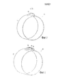
фиг.1 представляет собой общий вид корпуса авиационного двигателя в соответствии с одним из вариантов осуществления настоящего изобретения;figure 1 is a General view of the housing of an aircraft engine in accordance with one embodiment of the present invention;
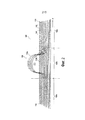
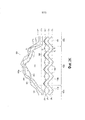
фиг.2 представляет собой схематичный общий вид волокнистой структуры для изготовления корпуса авиационного двигателя на Фиг.1;figure 2 is a schematic General view of the fibrous structure for the manufacture of the housing of the aircraft engine in figure 1;
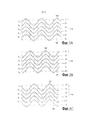
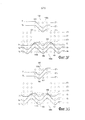
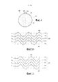
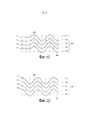
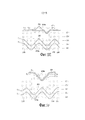
фиг.3A-3D представляют собой виды поперечного сечения в направлении утка в увеличенном масштабе, показывающие примерное расположение уточных нитей на участке волокнистой заготовки по фиг.1, который не содержит дугообразного участка;3A-3D are cross-sectional views in the direction of the weft on an enlarged scale, showing an exemplary arrangement of the weft yarns in the fiber preform portion of FIG. 1, which does not contain an arcuate portion;
фиг.3E-3H представляют собой виды поперечного сечения в направлении утка в увеличенном масштабе, показывающие множество последовательных плоскостей переплетения на участке заготовки по фиг.1, содержащем дугообразный участок;FIGS. 3E-3H are cross-sectional views in the direction of the weft on an enlarged scale, showing a plurality of successive weaving planes in the blank section of FIG. 1 containing an arcuate section;
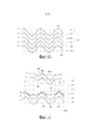
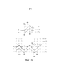
фиг.3I-3L представляют собой виды поперечного сечения в направлении основы в увеличенном масштабе, показывающие множество последовательных плоскостей переплетения на участке волокнистой заготовки по фиг.1, содержащем дугообразный участок;FIGS. 3I-3L are cross-sectional views in the direction of the warp on an enlarged scale, showing a plurality of successive weave planes in a portion of the fiber preform of FIG. 1 containing an arcuate portion;
фиг.4 показывает образование волокнистой структуры по фиг.2 при приготовлении для уплотнения;figure 4 shows the formation of the fibrous structure of figure 2 in preparation for compaction;
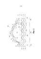
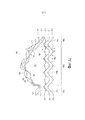
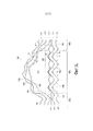
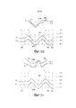
фиг.5A-5D представляют собой виды поперечного сечения в направлении утка в увеличенном масштабе, показывающие множество последовательных плоскостей переплетения на участке волокнистой заготовки, который не содержит дугообразный участок;5A-5D are enlarged cross-sectional views in the direction of the weft showing a plurality of successive weaving planes in a portion of a fiber preform that does not contain an arcuate portion;
фиг.5E-5H представляют собой виды поперечного сечения в направлении утка в увеличенном масштабе, показывающие множество последовательных плоскостей переплетения на участке волокнистой заготовки, содержащем дугообразный участок;5E-5H are cross-sectional views in the direction of the weft on an enlarged scale, showing a plurality of successive weave planes in a portion of a fiber preform containing an arcuate portion;
фиг.6 представляет собой общий вид другого варианта осуществления корпуса авиационного двигателя по настоящему изобретению;6 is a perspective view of another embodiment of an aircraft engine housing of the present invention;
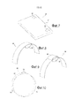
фиг.7 представляет собой общий вид варианта осуществления двери, снабженной петлями по настоящему изобретению;Fig. 7 is a perspective view of an embodiment of a door provided with hinges of the present invention;
фиг.8 представляет собой общий вид варианта осуществления части колпака, снабженного внутренней перегородкой по настоящему изобретению;Fig. 8 is a perspective view of an embodiment of a portion of a cap provided with an internal partition of the present invention;
фиг.9 представляет собой общий вид варианта осуществления части колпака, снабженного внутренней перегородкой и внешней перегородкой по настоящему изобретению; иFig.9 is a General view of an embodiment of a portion of a cap provided with an internal partition and an external partition of the present invention; and
фиг.10 представляет собой общий вид другого варианта осуществления корпуса авиационного двигателя по настоящему изобретению.10 is a perspective view of another embodiment of an aircraft engine housing of the present invention.
ОПИСАНИЕ ПРЕДПОЧТИТЕЛЬНЫХ ВАРИАНТОВ ОСУЩЕСТВЛЕНИЯ ИЗОБРЕТЕНИЯDESCRIPTION OF THE PREFERRED EMBODIMENTS OF THE INVENTION
Настоящее изобретение относится в целом к изготовлению волокнистых структур, пригодных для получения волокнистого упрочнения или преформ для изготовления деталей из композитного материала, которые содержат по меньшей мере один элемент дугообразной формы.The present invention relates generally to the manufacture of fibrous structures suitable for producing fiber reinforcement or preforms for the manufacture of parts from composite material that contain at least one arcuate element.
В соответствии с настоящим изобретением, участок волокнистой структуры, который предназначен для образования элемента дугообразной формы, изготавливают как единое целое с остальной частью волокнистой структуры. Более конкретно, и как объясняется подробно ниже, участок, который предназначен для образования элемента дугообразной формы, соткан из основных нитей, непрерывных с остальной частью структуры. Таким образом, усилия, прикладываемые к элементу дугообразной формы, могут восприниматься волокнистой структурой, которая представляет собой упрочнение деталей из композитного материала, в целом. Фиг.1 показывает корпус 10 авиационного двигателя, изготовленный из композитного материала, образующего колпак 11, содержащий коромысло 12 подвески, чтобы дать возможность крепления двигателя к пилону крыла самолета (не показано на фиг.1).In accordance with the present invention, a portion of the fibrous structure that is intended to form an arcuate element is made as a unit with the rest of the fibrous structure. More specifically, and as explained in detail below, a portion that is intended to form an arcuate element is woven from warp yarns continuous with the rest of the structure. Thus, the forces exerted on the arc-shaped element can be perceived by the fibrous structure, which is the strengthening of parts made of composite material as a whole. FIG. 1 shows an
Фиг.2 представляет собой очень схематичный вид волокнистой заготовки 100 для образования волокнистой преформы корпуса 10.Figure 2 is a very schematic view of a
Как показано схематично на фиг.2, волокнистую заготовку 100 получают посредством многослойного переплетения, осуществляемого известным образом посредством ткацкой машины жаккардового типа, содержащей пучок основных нитей 101 или прядей, составляющих множество слоев, основные нити взаимно связываются посредством уточных нитей 102.As shown schematically in FIG. 2, the
В показанном примере, многослойное переплетение представляет собой переплетение, полученное посредством плетения «интерлок». Термин «интерлок» используют в настоящем документе для обозначения переплетения, при котором каждый слой уточных нитей взаимно связывает множество слоев основных нитей, при этом все нити в данном уточном столбце имеют одинаковое движение в плоскости плетения.In the example shown, a multilayer weave is a weave obtained by weaving "interlock". The term “interlock” is used herein to mean weaving in which each layer of weft yarns interconnects a plurality of layers of warp yarns, with all yarns in this weft column having the same movement in the weaving plane.
Можно использовать другие известные типы многослойного переплетения, например, такие как те, которые описаны в документе WO 2006/136755, содержание которого включено в настоящий документ в качестве ссылки.Other known types of multilayer weaving can be used, for example, such as those described in WO 2006/136755, the contents of which are incorporated herein by reference.
В конкретном, но не эксклюзивном способе, волокнистая заготовка по настоящему изобретению может быть получена плетением с использованием волокнистых нитей, изготовленных из углерода, из керамики, например волокна из карбида кремния, или даже из металла, такого как титан.In a specific, but not exclusive, method, the fibrous preform of the present invention can be obtained by weaving using fibrous filaments made of carbon, ceramic, for example fibers of silicon carbide, or even metal, such as titanium.
Как показано на фиг.2, волокнистая заготовка 100 выполнена в виде полосы 110, продолжающейся в продольном направлении X, полоса предназначена для образования колпака 11 корпуса 10 после придания заготовке формы, в ней содержится дугообразный участок 120, который предназначен для образования коромысла 12 подвески, содержащегося на волокнистой заготовке.As shown in figure 2, the
На участках 100a и 100c волокнистой заготовки 100, которые располагаются по обе стороны участка 100b, который содержит дугообразный участок 120, все слои основных нитей содержат основные нити одинаковой длины, и уточные нити используют для взаимного связывания каждого слоя основных нитей по меньшей мере со смежным слоем (слоями) основных нитей, с тем, чтобы получить на участках 100a и 100c заготовки структуру, в которой все слои основных нитей являются взаимосвязанными.In
На участке 100b, полоса 110 разделена на две суб-полосы 110a и 110b посредством области 111 с отсутствием взаимного связывания, между образованными группами, первой группой 101a слоев основных нитей и второй группой 101b слоев основных нитей. Суб-полосу 110a изготавливают по меньшей мере из двух смежных или последовательных слоев основных нитей, взятых из первого слоя основных нитей, содержащихся на одной поверхности волокнистой заготовки 100, верхней поверхности в этом примере, в то время как суб-полосу 110b изготавливают из слоев основных нитей, лежащих ниже слоев суб-полосы 110a. В соответствии с настоящим изобретением, основные нити суб-полосы 110a имеют большую длину, чем нити лежащих ниже слоев основных нитей суб-полосы 110b. Это различие по длине может быть получено посредством скорости вытягивания основных нитей слоев основных нитей суб-полосы 110a, которая больше, чем скорость вытягивания, прикладываемая к основным нитям слоев основных нитей суб-полосы 110b. В одном из вариантов осуществления, длина основных нитей слоев основных нитей суб-полосы 110a может быть увеличена по отношению к длине основных нитей суб-полосы 110b посредством вытягивания основных нитей слоев основных нитей суб-полосы 110a.At
Фиг.3A-3D представляют собой схемы, показывающие один из вариантов осуществления многослойного переплетения посредством переплетения «интерлок» на участках 100a или 100c заготовки 100, эти фигуры представляют собой соответствующие фрагментарные виды в увеличенном масштабе последовательных плоскостей поперечного сечения в направлении основы. В этом примере, заготовка 100 содержит шесть слоев основных нитей 101, продолжающихся в направлении X. На фиг.3A-3D, шесть слоев C1-C6 основных нитей взаимно связываются посредством уточных нитей T1-T5. Для целей упрощения, показано только шесть слоев основных нитей и пять слоев уточных нитей, естественно, продолжающихся вдоль направлений по ширине и по толщине волокнистой структуры, которая должна быть получена. На самом деле, эта структура может быть получена посредством некоторых количеств слоев основных и уточных нитей и с некоторым количеством нитей на слой, которое гораздо больше.3A-3D are diagrams showing one embodiment of multilayer weaving by interlock weaving in
Фиг.3E-3H представляют собой соответствующие увеличенные фрагментарные виды последовательных плоскостей поперечного сечения в направлении основы плетения для участка 100b заготовки 100, который содержит суб-полосу 110a, содержащую как дугообразный участок 120, так и суб-полосу 110b. На участке 100b уточные нити T3 не связывают взаимно слои C3 и C4 основных нитей, так что заготовка 100 имеет отсутствие взаимного связывания 103 между суб-полосами 110a и 110b с образованием области 111 с отсутствием взаимного связывания. Фиг.3E-3H соответствуют последовательным плоскостям плетения, расположенным на выступающем участке дугообразного участка 120.3E-3H are corresponding enlarged fragmentary views of successive cross-sectional planes in the direction of the weaving base for a
На фиг.3E, слои C"1, C"2 и C"3, которые соответствуют соответствующим фракциям основных нитей в трех слоях основных нитей C1, C2 и C3, которые для использования при образовании дугообразного участка 120 взаимосвязаны друг с другом посредством уточных нитей T1 и T2, в то время как слои C'1, C'2 и C'3, которые соответствуют остальным основным нитям в трех слоях основных нитей C1, C2 и C3, не переплетены. Три лежащих ниже слоя основных нитей C4, C5 и C6 взаимосвязаны посредством уточных нитей T3, T4 и T5.3E, layers C "1, C" 2 and C "3, which correspond to the respective fractions of the warp yarns in the three layers of warp yarns C1, C2 and C3, which, for use in forming an
Фиг.3F,3G и 3H показывают соответственно три последовательных плоскости плетения, которые получают после плоскости плетения на фиг.3E. Плоскости переплетения фиг.3E-3H повторяются по всей длине дугообразного участка 120.FIGS. 3F, 3G, and 3H show, respectively, three successive weaving planes that are obtained after the weaving plane in FIG. 3E. The weave planes of FIGS. 3E-3H are repeated along the entire length of the
Фиг.3I-3L представляют собой соответствующие увеличенные фрагментарные виды последовательных плоскостей поперечного сечения в уточном направлении плетения заготовки 100, включающей участки 100b. На участке 100b уточные нити двух слоев уточных нитей C"T1 и C"T2, и принадлежащие суб-полосе 110a, переплетают с основными нитями ch1, ch2 и ch3 слоев основных нитей C"1, C"2 и C"3 (фиг.3E - 3H), в то время как остальные уточные нити лежащих ниже слоев уточных нитей CT3, CT4 и CT5, которые формируют участок суб-полосы 110b, переплетены с основными нитями ch4, ch5 и ch6 слоев основных нитей C4, C5 и C6 (фиг.3E-3H).FIGS. 3I-3L are corresponding enlarged fragmentary views of successive cross-sectional planes in the weaving weaving direction of the
Как показано на фиг.3I-3L, на участке 100b количества уточных нитей T1 и T2, содержащихся соответственно в слоях C"T1 и C"T2, больше, чем количество уточных нитей T3, T4 и T5, содержащихся соответственно в слоях CT3, CT4 и CT5. Это служит для поддержания постоянной плотности ткани в суб-полосе 110a по отношению к суб-полосе 110b и остальной части заготовки 100, то есть количество уточных нитей на единицу длины в направлении основы является постоянным для двух суб-полос 110a и 110b, при этом это осуществляется, несмотря на увеличение длины основных нитей в суб-полосе 110a. Если в суб-полосы 110a и 110b вставляют одинаковое количество уточных нитей, тогда расстояние между двумя соседними уточными нитями в направление основы в суб-полосе 110a может быть уменьшено посредством вставки уточных нитей, которые тяжелее, чем уточные нити, вставленные в суб-полосу 110b.3I-3L, in
Плотность ткани в суб-полосе 110a может также быть меньше (или более свободной), чем в суб-полосе 110b, то есть количество уточных нитей на единицу длины в направлении основы в суб-полосе 110a меньше, чем в суб-полосе 110b.The density of the fabric in sub-band 110a may also be less (or freer) than in
В конце плетения непереплетенные основные нити, то есть, в этом примере, основные нити слоев C'1, C'2 и C'3 (фиг.3E - 3H), и непереплетенные уточные нити, то есть части уточных нитей T1 и T2, расположенные вне слоев C"2 и C"3, обрезают для извлечения заготовки 100, как показано на фиг.2, которая показывает заготовку так, как ее получают после многослойного плетения и перед каким-либо преданием формы. В одном из вариантов осуществления, дугообразный участок можно также отрезать с использованием струи воды, например, для уменьшения ее толщины и/или для модификации ее профиля по ширине в направлении утка.At the end of weaving, the unwoven warp yarns, that is, in this example, the warp yarns of layers C'1, C'2 and C'3 (Figs. 3E - 3H), and the unwoven weft yarns, i.e. parts of the weft yarns T1 and T2, located outside the layers C "2 and C" 3, cut to remove the
Дополнительная длина основных нитей в суб-полосе 110a на участке 100b и область 111 с отсутствием взаимного связывания, которую образуют при плетении между суб-полосами 110a и 110b, вместе делают возможным образование дугообразного участка 120.The additional length of the warp yarns in the sub-band 110a in the
Дугообразный участок волокнистой структуры по настоящему изобретению изготавливают из множества слоев основных нитей, которые взаимосвязаны. По отношению к остальной части слоев, лежащих ниже полосы, эта часть определяет полость, которая сохраняется в готовой детали, то есть после того, как текстуру уплотняют посредством матрицы.The arcuate portion of the fibrous structure of the present invention is made from multiple layers of warp yarns that are interconnected. In relation to the rest of the layers below the strip, this part defines the cavity that is stored in the finished part, that is, after the texture is compacted by means of a matrix.
После этого, волокнистую заготовку уплотняют с образованием корпуса 10 на фиг.1. Для этой цели, и как показано на фиг.4, волокнистой заготовке 100 предают форму вокруг барабана 150, и в качестве примера, два свободных конца заготовки 100 могут сшиваться вместе перед указанным уплотнением или они могут просто накладываться друг на друга, при этом их концы связываются вместе при уплотнении. Это дает волокнистую преформу 130, готовую для уплотнения. Вставка 160, соответствующая внутренней форме дугообразного участка 120, также располагается в ней с тем, чтобы поддержать форму дугообразного участка при уплотнении и предотвратить образование матрицы в объеме, присутствующем между дугообразным участком 120 и нижней полосой заготовки. В вариантах осуществления, волокнистая заготовка имеет длину, соответствующую нескольким длинам корпуса по его периферии, и дугообразный участок может располагаться на участке заготовки, который располагается на барабане, в ходе последнего витка, или, наоборот, в ходе начального витка, или в ходе витков с отверстиями, делающими возможным прохождение дугообразного участка через следующие витки, когда они предусмотрены в заготовке.After that, the fibrous preform is compacted with the formation of the
Уплотнение волокнистой преформы заключается в заполнении пор преформы во всем объеме или в его части посредством использования материала, который образует матрицу.The densification of the fibrous preform is to fill the pores of the preform in whole or in part by using the material that forms the matrix.
Матрица композитного материала, образующего обтекаемую структуру, может быть получена известным способом с использованием жидкостной техники.The matrix of the composite material forming the streamlined structure can be obtained in a known manner using liquid technology.
Жидкостная техника заключается в импрегнировании преформы жидкостной композицией, содержащей органический предшественник материала матрицы. Органический предшественник обычно находится в форме полимера, такого как смола, возможно, разбавленного в растворителе. Преформу помещают в форму для формования, которая может закрываться непроницаемым образом и которая содержит полость в форме формованной готовой детали. В этом примере, преформу располагают между формой для формования и ее ответной частью соответственно, содержащими наружную форму и внутреннюю форму (такую как барабан 150) корпуса, который нужно изготовить. После этого, форму для формования закрывают и впрыскивают жидкий предшественник матрицы (например, смолу) до заполнения всей полости формы для формования, для импрегнирования всей волокнистой части преформы.The liquid technique is to impregnate the preform with a liquid composition containing an organic precursor of the matrix material. The organic precursor is usually in the form of a polymer, such as a resin, possibly diluted in a solvent. The preform is placed in a mold for molding, which can be closed in an impermeable manner and which contains a cavity in the form of a molded finished part. In this example, a preform is positioned between the molding mold and its counterpart, respectively, containing an outer mold and an inner mold (such as drum 150) of the body to be manufactured. After that, the mold for molding is closed and the liquid matrix precursor (for example, resin) is injected until the entire cavity of the molding mold is filled to impregnate the entire fibrous part of the preform.
Предшественник преобразуется в органическую матрицу, то есть полимеризуется посредством применения термической обработки, как правило, посредством нагрева формы для формования после устранения любого растворителя, и после отверждения полимера преформа продолжает удерживаться внутри формы для формования и, таким образом, приобретает форму детали, которая должна быть изготовлена. Органическая матрица может быть получена в частности, из эпоксидных смол, таких, например, как коммерчески доступная эпоксидная смола с высокими рабочими характеристиками или жидкие предшественники для углеродных или керамических матриц.The precursor is converted to an organic matrix, that is, polymerized by heat treatment, typically by heating the mold to form after removing any solvent, and after curing the polymer, the preform continues to be held inside the mold and thus takes on the shape of the part to be made. The organic matrix can be obtained in particular from epoxy resins, such as, for example, commercially available high performance epoxy resins or liquid precursors for carbon or ceramic matrices.
При образовании углеродной или керамической матрицы термическая обработка состоит в пиролизе органического предшественника для преобразования органической матрицы в углеродную или керамическую матрицу в зависимости от используемого предшественника и условий пиролиза. В качестве примера, жидкие предшественники углерода могут представлять собой смолы, имеющие высокое содержание кокса, такие как фенольные смолы, в то время как жидкие предшественники керамики и в частности, SiC, могут представлять собой смолы типа поликарбосилана (PCS), или полититанокарбосилана (PTCS), или полисилазана (PSZ). Несколько последовательных циклов, начиная от импрегнирования и до термической обработки, могут осуществляться для достижения такой степени уплотнения, которая является требуемой.In the formation of a carbon or ceramic matrix, the heat treatment consists in pyrolyzing an organic precursor to convert the organic matrix into a carbon or ceramic matrix, depending on the precursor used and the pyrolysis conditions. As an example, liquid carbon precursors can be resins having a high coke content, such as phenolic resins, while liquid ceramics precursors, and in particular SiC, can be polycarbosilane (PCS), or polytitanocarbosilane (PTCS) resins. or polysilazane (PSZ). Several successive cycles, from impregnation to heat treatment, can be carried out to achieve the degree of compaction that is required.
В одном из аспектов настоящего изобретения, волокнистая преформа может уплотняться посредством хорошо известного способа формования с переносом смолы (RTM). По способу RTM, волокнистая преформа 130 вместе с барабаном 150 и вставкой 160 (фиг.4) помещается в форму для формования, представляющую собой внешнюю форму корпуса, который должен быть изготовлен. Термоусадочную смолу впрыскивают во внутреннее пространство, образованное между деталью из жесткого материала и формой для формования, и она содержит волокнистую преформу. Как правило, внутри этого внутреннего пространства устанавливают градиент давления между положением, в котором впрыскивают смолу, и отверстиями для высвобождения смолы, для контроля и оптимизации импрегнирования преформы смолой.In one aspect of the present invention, the fibrous preform may be densified by a well known resin transfer molding (RTM) method. According to the RTM method, the
В качестве примера, используемая смола может представлять собой эпоксидную смолу. Смолы, пригодные для способов RTM, хорошо известны. Они предпочтительно имеют низкую вязкость, чтобы сделать проще их впрыскивание между волокнами. Температурный класс и/или химическая природа смолы определяется/определяются как зависимость от термомеханического напряжения, воздействию которого должна подвергаться деталь. После впрыскивания смолы по всему упрочнению, она полимеризуется посредством термической обработки в соответствии со способом RTM.As an example, the resin used may be an epoxy resin. Resins suitable for RTM methods are well known. They preferably have a low viscosity to make it easier to inject them between the fibers. The temperature class and / or chemical nature of the resin is defined / defined as the dependence on the thermomechanical stress to which the part should be exposed. After injecting the resin throughout the hardening, it is polymerized by heat treatment in accordance with the RTM method.
После впрыскивания и полимеризации, деталь вынимают из формы для формования. Наконец деталь обрезают для удаления избытка смолы, и приливы подвергают воздействию механической обработки для механической обработки корпуса 10 на фиг.1.After injection and polymerization, the part is removed from the mold. Finally, the part is cut to remove excess resin, and the tides are subjected to machining for machining the
Фиг.5A-5H представляют собой увеличенные фрагментарные схематичное виды в последовательных плоскостях поперечных сечений в направлении основы, показывающие варианты переплетения «интерлок» для многослойного плетения заготовки 200 с образованием корпуса авиационного двигателя, сходного с корпусом 10 на фиг.1, то есть имеющего колпак с дугообразным коромыслом подвески, включенным в него. Это плетение отличается от фиг.3A-3H только тем, что используют всего лишь два слоя основных нитей для образования дугообразного участка 220. В этом примере, заготовка 200 содержит пять слоев C10-C50 основных нитей 201, которые взаимосвязаны посредством уточных нитей 201, упоминаемых как T10-T40, на фиг.5A-5D, при этом заготовка образует полосу 210. На фиг.5E-5H, которые соответствуют участку волокнистой заготовки, где формируется дугообразный участок 220 волокнистой заготовки, уточные нити 220 не связывают взаимно слои C20 и C30 основных нитей, так что заготовка 200 имеет отсутствие взаимного связывания 203 с разделением на две суб-полосы 210a и 210b. Суб-полоса 210a, соответствующая дугообразному участку 220 заготовки 200, содержит основные нити, длина которых больше, чем у основных нитей суб-полосы 210B. На фиг.5E-5H, слои C"10 и C"20, которые соответствуют соответствующим фракциям основных нитей двух слоев C10 и C20 основных нитей, которые должны формировать дугообразный участок 220, взаимосвязаны посредством уточных нитей T10 и T20, в то время как слои C'10 и C'20, которые соответствуют остальным основным нитям двух слоев основных нитей C10 и C20, не переплетаются. Три лежащих ниже основных нити C30, C40 и C50 взаимосвязаны посредством уточных нитей T30 и T40. Рисунок плетения по фиг.5E-5H повторяется по всей длине дугообразного участка 220. Количество уточных нитей, вставленных в суб-полосу 210a, может быть больше, чем количество уточных нитей, вставленных в суб-полосу 210b, для поддержания постоянной плотности ткани в направление основы между этими двумя суб-полосами, вместо увеличения длины основных нитей в суб-полосе 210a. Также возможно, чтобы плотность ткани в направлении основы в суб-полосе 210a была меньше (или реже) по отношению к плотности ткани в направлении основы в суб-полосе 210b, при этом одинаковое количество уточных нитей вставляется в суб-полосы, как в 210a, так и в 210b. Если в суб-полосы вставляется одинаковое количество уточных нитей, как в 210a, так и в 210b, тогда расстояние между двумя соседними уточными нитями в направлении основы в суб-полосе 210a может быть уменьшено посредством вставки уточных нитей с массой, которая больше, чем масса уточных нитей, вставленных в суб-полосу 210b.5A-5H are enlarged fragmentary schematic views in successive planes of cross-sections in the direction of the warp, showing interlock weaving options for multilayer weaving of the workpiece 200 to form an aircraft engine housing similar to that of
Настоящее изобретение не ограничивается образованием детали в форме тела вращения, содержащего один элемент дугообразной формы. В качестве неограничивающих примеров фиг.6-10 показывают другие типы деталей, которые могут быть изготовлены в соответствии с настоящим изобретением. Фиг.6 показывает корпус авиационного двигателя 20, который содержит колпак 21 с тремя смежными коромыслами 22, 23 и 24 подвески, образованными на нем, в направлении по ширине колпака. Фиг.10 показывает корпус авиационного двигателя 60, содержащего колпак 61 с тремя коромыслами 62, 63 и 64 подвески, образованными на нем, которые распределены по периферии колпака.The present invention is not limited to the formation of a part in the form of a body of revolution containing one arc-shaped element. By way of non-limiting examples, FIGS. 6-10 show other types of parts that can be manufactured in accordance with the present invention. 6 shows the housing of an
При таких обстоятельствах, при изготовлении волокнистой структуры по настоящему изобретению, три дугообразных участка формируются таким же способом, как описано выше для изготовления участков 120 и 220, эти три дугообразных участка изготавливают с использованием основных нитей, которые расположены рядом в направлении утка волокнистой заготовки, при этом длина основных нитей на этих, здесь - дугообразных, участках, естественно, больше, чем длина основных нитей в лежащих ниже слоях основных нитей, а также чем у основных нитей, расположенных между двумя дугообразными участками или вне их в направлении утка.Under such circumstances, in the manufacture of the fibrous structure of the present invention, three arcuate sections are formed in the same manner as described above for the manufacture of
Фиг.7 показывает дверь 30, содержащую панель 31, соединенную с двумя петлями 32 и 33. В этом примере, при изготовлении волокнистой структуры по настоящему изобретению, два дугообразных участка формируют таким же способом, как описано выше для изготовления дугообразных участков 120 и 220, эти два дугообразных участка изготавливают с использованием основных нитей, которые располагаются смежно в направлении утка волокнистой заготовки, основные нити, используемые для каждого из этих двух дугообразных участков, располагаются вблизи соответствующего края заготовки в направлении утка. Длина основных нитей на этих двух участках, естественно, больше, чем длина основных нитей в лежащих ниже слоях основных нитей, а также, чем длина основных нитей расположенных между двумя дугообразными участками или вне дугообразных участков в направлении утка.7 shows a
Фиг.8 показывает часть 40 колпака, содержащую внутреннюю перегородку 41, которую можно использовать в качестве направляющей для проводов или в качестве канала. Эту деталь получают посредством изготовления волокнистой структуры, которая содержит дугообразный участок по всей ее ширине в направлении утка волокнистой заготовки, этот дугообразный участок формируется таким же способом, как описано выше для изготовления участков 120 и 220, только волокнистая заготовка уплотняется, когда он удерживается с такой кривизной, которая является обратной по отношению к заготовке 100 и 200.FIG. 8 shows a
Фиг.9 показывает часть 50 колпака, содержащую наружную перегородку 51, расположенную на наружной поверхности 50a части колпака, и внутреннюю перегородку 52, расположенную на внутренней поверхности 50b части 50 колпака. В этом примере, волокнистая структура, из которой изготавливают волокнистое упрочнение части 50 колпака, содержит первый дугообразный участок, продолжающийся по одной из поверхностей волокнистой структуры, и второй дугообразный участок, продолжающийся по другой поверхности волокнистой структуры. Первый и второй дугообразный участки образуют соответственно посредством основных нитей по меньшей мере двух смежных слоев основных нитей, содержащихся на каждой из поверхностей волокнистой структуры. Эти первый и второй дугообразные участки изготавливают таким же образом, как описано выше для изготовления участков 120 и 220, то есть с основными нитями, которые являются продолжением остальной части структуры, но которые имеют длину, которая больше, чем длина основных нитей по меньшей мере двух лежащих ниже слоев основных нитей структуры, основные нити каждого дугообразного участка не имеют взаимного связывания с другими основными нитями волокнистой структуры.9 shows a
В соответствии с настоящим изобретением, волокнистое упрочнение коромысел 22-24 подвески, петель 32 и 33, внутренней перегородки 41 и внутренней и наружной перегородок 51 и 52, все они образованы с использованием основных нитей, непрерывных с волокнистым упрочнением остальной части структуры, то есть волокнистого упрочнения соответственно колпака 21, панели 31, части колпака 40 и части колпака 50.In accordance with the present invention, the fiber reinforcement of the rocker arms 22-24 of the suspension,
Форма и размеры деталей из композитного материала, изготовленных со структурой волокон по настоящему изобретению, могут изменяться и не должны конкретно ограничиваться деталями в форме колпака или форме панели, но могут применяться к деталям любой другой формы, на которых должны изготавливаться один или более дугообразных участков.The shape and dimensions of parts made of composite material made with the fiber structure of the present invention can vary and should not be specifically limited to parts in the form of a cap or panel shape, but can be applied to parts of any other shape on which one or more arcuate sections are to be made.
Claims (11)
Applications Claiming Priority (3)
| Application Number | Priority Date | Filing Date | Title |
|---|---|---|---|
| FR1060408A FR2968679B1 (en) | 2010-12-13 | 2010-12-13 | FIBROUS STRUCTURE FOR A PIECE OF COMPOSITE MATERIAL HAVING ONE OR MORE ARCHEME-SHAPED PARTS |
| FR1060408 | 2010-12-13 | ||
| PCT/FR2011/052868 WO2012080617A1 (en) | 2010-12-13 | 2011-12-05 | Fibrous structure for a part made of composite material having one or more arch-shaped portions |
Publications (2)
| Publication Number | Publication Date |
|---|---|
| RU2013132219A RU2013132219A (en) | 2015-01-20 |
| RU2578996C2 true RU2578996C2 (en) | 2016-03-27 |
Family
ID=43821920
Family Applications (1)
| Application Number | Title | Priority Date | Filing Date |
|---|---|---|---|
| RU2013132219/12A RU2578996C2 (en) | 2010-12-13 | 2011-12-05 | Fibrous structure for part made of composite material, comprising one or more of arcuate sections |
Country Status (9)
| Country | Link |
|---|---|
| US (1) | US9365956B2 (en) |
| EP (1) | EP2652185B1 (en) |
| JP (1) | JP6017445B2 (en) |
| CN (1) | CN103261499B (en) |
| BR (1) | BR112013014578B1 (en) |
| CA (1) | CA2820415C (en) |
| FR (1) | FR2968679B1 (en) |
| RU (1) | RU2578996C2 (en) |
| WO (1) | WO2012080617A1 (en) |
Cited By (1)
| Publication number | Priority date | Publication date | Assignee | Title |
|---|---|---|---|---|
| RU2802406C1 (en) * | 2022-11-07 | 2023-08-28 | Сергей Леонидович Поляков | Multi-layer double-sided structured material |
Families Citing this family (19)
| Publication number | Priority date | Publication date | Assignee | Title |
|---|---|---|---|---|
| FR2970715B1 (en) * | 2011-01-21 | 2014-10-17 | Snecma | MULTI-LAYER FABRIC FIBROUS STRUCTURE HAVING HOLLOW TUBULAR PART, MANUFACTURING METHOD AND COMPOSITE PIECE COMPRISING THE SAME |
| US9833930B2 (en) | 2012-10-23 | 2017-12-05 | Albany Engineered Composites, Inc. | Circumferential stiffeners for composite fancases |
| FR3002547B1 (en) * | 2013-02-22 | 2015-07-17 | Aircelle Sa | METHOD FOR WEAVING A DOUBLE CRYSTAL FABRIC IN THE CHAIN SENSE AND PREFORM USING SUCH FABRIC |
| FR3002548A1 (en) * | 2013-02-22 | 2014-08-29 | Aircelle Sa | METHOD FOR WEAVING A RELIEF FABRIC, WEAVING FABRIC FOR CARRYING OUT THE METHOD, AND PREFORM USING SUCH A RELIEF TISSUE |
| FR3002549B1 (en) * | 2013-02-22 | 2015-03-27 | Aircelle Sa | MULTI-FEED WOVEN FABRIC, WEAVING METHOD USING SUCH A WEAVING MACHINE, AND A CRYSTAL FABRIC THUS OBTAINED. |
| WO2014163676A1 (en) * | 2013-03-13 | 2014-10-09 | Lazur Andrew J | Compliant composite component and method of manufacture |
| FR3009315B1 (en) * | 2013-07-30 | 2015-12-18 | Aircelle Sa | METHOD FOR MANUFACTURING A WOVEN PREFORM FOR A BEAM IN COMPOSITE MATERIALS HAVING TRANSVERSE INNER REINFORCEMENTS |
| FR3018286B1 (en) * | 2014-03-10 | 2016-05-27 | Aircelle Sa | WOVEN PREFORM FOR REALIZING A CIRCUMFERENTIAL OR TORIC REINFORCEMENT WITH A SECTION IN OMEGA |
| CN104264312B (en) * | 2014-09-10 | 2016-04-13 | 淄博银仕来纺织有限公司 | The weaving method of wide cut tubing |
| FR3027549B1 (en) * | 2014-10-23 | 2017-09-08 | Snecma | ASSEMBLY BY A MECHANICAL ANCHOR ELEMENT BETWEEN TWO PIECES OF WHICH ONE IS REALIZED IN COMPOSITE MATERIAL |
| JP5999744B1 (en) * | 2014-12-10 | 2016-09-28 | 内野株式会社 | Weaving method of multiple gauze and multiple gauze fabric |
| JP6377568B2 (en) * | 2015-04-27 | 2018-08-22 | 株式会社オルセン | Three-dimensional fabric |
| CN110997816B (en) * | 2017-07-31 | 2022-08-23 | 美国陶氏有机硅公司 | Dual curable silicone composition |
| WO2019074881A1 (en) | 2017-10-12 | 2019-04-18 | Albany Engineered Composites, Inc. | Three-dimensional woven preforms for omega stiffeners |
| US20190285028A1 (en) * | 2018-03-16 | 2019-09-19 | Mra Systems, Llc. | Thrust reverser cascade |
| JP6564971B2 (en) * | 2018-03-27 | 2019-08-28 | 株式会社オルセン | Fastening tool using three-dimensional fabric and method for setting up tent etc. using this fastening tool |
| FR3084088B1 (en) * | 2018-07-23 | 2020-10-02 | Safran | FIBROUS TEXTURE FOR IMPACT RESISTANCE IMPACT RESISTANCE COMPOSITE MATERIAL |
| FR3092034B1 (en) * | 2019-01-30 | 2022-12-02 | Safran Aircraft Engines | Casing in composite material with local thickness variation |
| FR3136189A1 (en) * | 2022-06-02 | 2023-12-08 | Safran Aircraft Engines | Composite material part with improved shock absorption capacity, and method of manufacturing such a part |
Citations (4)
| Publication number | Priority date | Publication date | Assignee | Title |
|---|---|---|---|---|
| EP0391745A1 (en) * | 1989-04-06 | 1990-10-10 | Bp Chemicals ( Hitco) Inc. | Integrally woven multi-apertured multi-layer angle interlock fabrics |
| US5098756A (en) * | 1989-01-25 | 1992-03-24 | Henderson Mark P | Elastic self-extinguishing strap material |
| RU2117736C1 (en) * | 1997-01-23 | 1998-08-20 | Акционерное общество закрытого типа "Русстек" | Fibrous base for composite insulating and/or roofing material |
| US20020148525A1 (en) * | 2001-02-13 | 2002-10-17 | Yasuaki Matsui | Vehicle running assistance fabric |
Family Cites Families (13)
| Publication number | Priority date | Publication date | Assignee | Title |
|---|---|---|---|---|
| JPS6297938A (en) * | 1985-10-23 | 1987-05-07 | 敷島カンバス株式会社 | Method for weaving fabric for three-dimensional molding |
| JPH0243893Y2 (en) * | 1986-07-23 | 1990-11-21 | ||
| DE3872911T2 (en) * | 1987-03-31 | 1992-12-03 | Asahi Chemical Ind | FABRICS WITH A MULTILAYER STRUCTURE AND A COMPOSITE MATERIAL CONTAINING THIS FABRIC. |
| DE69121662T2 (en) * | 1990-10-18 | 1997-01-23 | Nippon Oil Co Ltd | Multi-layer tubular fabric and process for its manufacture |
| JPH05230735A (en) * | 1992-02-17 | 1993-09-07 | Fukukou Orimono Kk | Woven fabric and production thereof |
| FR2759096B1 (en) * | 1997-02-04 | 1999-02-26 | Snecma | LINKED MULTILAYER TEXTURE FOR STRUCTURAL COMPOSITE MATERIALS |
| CN1053613C (en) * | 1998-09-28 | 2000-06-21 | 天津纺织工学院 | Multi-ply fabrics composition materials and its formation mould and method therefor |
| FR2887601B1 (en) | 2005-06-24 | 2007-10-05 | Snecma Moteurs Sa | MECHANICAL PIECE AND METHOD FOR MANUFACTURING SUCH A PART |
| FR2902802B1 (en) * | 2006-06-21 | 2008-12-12 | Snecma Propulsion Solide Sa | FIBROUS REINFORCING STRUCTURE FOR A PIECE OF COMPOSITE MATERIAL AND PART COMPRISING THE SAME |
| FR2902803B1 (en) * | 2006-06-21 | 2008-11-14 | Snecma Propulsion Solide Sa | FIBROUS REINFORCING STRUCTURE FOR A PIECE OF COMPOSITE MATERIAL AND PART COMPRISING THE SAME |
| FR2904167B1 (en) * | 2006-07-21 | 2008-10-17 | Laudren Electronique Sarl | METHOD AND DEVICE FOR REMOVING ECHO IN A DIGITS COMMUNICATION SYSTEM |
| FR2939129B1 (en) * | 2008-11-28 | 2014-08-22 | Snecma Propulsion Solide | TURBOMACHINE TURBINE IN COMPOSITE MATERIAL AND PROCESS FOR MANUFACTURING THE SAME. |
| FR2940167B1 (en) | 2008-12-24 | 2012-12-21 | Messier Dowty Sa | METHOD FOR BONDING A STRUCTURAL ELEMENT IN COMPOSITE MATERIAL TO A TUBE |
-
2010
- 2010-12-13 FR FR1060408A patent/FR2968679B1/en not_active Expired - Fee Related
-
2011
- 2011-12-05 US US13/993,472 patent/US9365956B2/en active Active
- 2011-12-05 RU RU2013132219/12A patent/RU2578996C2/en active
- 2011-12-05 CA CA2820415A patent/CA2820415C/en active Active
- 2011-12-05 CN CN201180059797.7A patent/CN103261499B/en active Active
- 2011-12-05 BR BR112013014578-1A patent/BR112013014578B1/en active IP Right Grant
- 2011-12-05 JP JP2013543854A patent/JP6017445B2/en active Active
- 2011-12-05 WO PCT/FR2011/052868 patent/WO2012080617A1/en active Application Filing
- 2011-12-05 EP EP11805095.4A patent/EP2652185B1/en active Active
Patent Citations (4)
| Publication number | Priority date | Publication date | Assignee | Title |
|---|---|---|---|---|
| US5098756A (en) * | 1989-01-25 | 1992-03-24 | Henderson Mark P | Elastic self-extinguishing strap material |
| EP0391745A1 (en) * | 1989-04-06 | 1990-10-10 | Bp Chemicals ( Hitco) Inc. | Integrally woven multi-apertured multi-layer angle interlock fabrics |
| RU2117736C1 (en) * | 1997-01-23 | 1998-08-20 | Акционерное общество закрытого типа "Русстек" | Fibrous base for composite insulating and/or roofing material |
| US20020148525A1 (en) * | 2001-02-13 | 2002-10-17 | Yasuaki Matsui | Vehicle running assistance fabric |
Cited By (1)
| Publication number | Priority date | Publication date | Assignee | Title |
|---|---|---|---|---|
| RU2802406C1 (en) * | 2022-11-07 | 2023-08-28 | Сергей Леонидович Поляков | Multi-layer double-sided structured material |
Also Published As
| Publication number | Publication date |
|---|---|
| BR112013014578A2 (en) | 2016-09-20 |
| CN103261499A (en) | 2013-08-21 |
| RU2013132219A (en) | 2015-01-20 |
| US20130270389A1 (en) | 2013-10-17 |
| CA2820415A1 (en) | 2012-06-21 |
| BR112013014578B1 (en) | 2020-12-01 |
| FR2968679B1 (en) | 2014-02-07 |
| EP2652185A1 (en) | 2013-10-23 |
| CA2820415C (en) | 2018-03-20 |
| JP6017445B2 (en) | 2016-11-02 |
| US9365956B2 (en) | 2016-06-14 |
| JP2014506304A (en) | 2014-03-13 |
| CN103261499B (en) | 2014-12-31 |
| WO2012080617A1 (en) | 2012-06-21 |
| EP2652185B1 (en) | 2015-06-24 |
| FR2968679A1 (en) | 2012-06-15 |
Similar Documents
| Publication | Publication Date | Title |
|---|---|---|
| RU2578996C2 (en) | Fibrous structure for part made of composite material, comprising one or more of arcuate sections | |
| JP6254532B2 (en) | Fiber reinforced structure for composite parts with thin wall | |
| JP2014506304A5 (en) | ||
| JP6557223B2 (en) | Composite propeller blade for aircraft | |
| JP6092244B2 (en) | Fiber structure with variable amount of yarn | |
| RU2533384C2 (en) | Blade of propeller for aircraft | |
| JP5913303B2 (en) | Blade with integral composite girder | |
| RU2586423C2 (en) | Turbine engine blade with built-in shank, made from composite material | |
| JP7237936B2 (en) | Woven fibrous structure for forming casing preform | |
| US9550340B2 (en) | Composite material part comprising fixing means | |
| RU2695828C2 (en) | Reinforcing fibrous structure for parts from composite material with wide range of thickness | |
| CN114728440B (en) | Braided fiber preform made of composite material for manufacturing fan blades | |
| CN115003482B (en) | Braided fiber preform for producing composite parts, in particular turbine blades | |
| CN112513352B (en) | Fiber texture for shear strength enhanced shells made from composite materials | |
| CN111448346A (en) | Fiber structure and composite material part comprising same | |
| CN114375250B (en) | Method for producing a fibrous preform for reinforcement of a component made of composite material with a large local thickness variation | |
| US11951694B2 (en) | Fibrous texture for a casing made of composite material with hybrid warp strands | |
| CN113365802B (en) | Shell made of composite material with local thickness variation | |
| CN116940724A (en) | Fiber texture for feathered composite blades |
Legal Events
| Date | Code | Title | Description |
|---|---|---|---|
| PD4A | Correction of name of patent owner |