JP6006232B2 - Linear actuator - Google Patents
Linear actuator Download PDFInfo
- Publication number
- JP6006232B2 JP6006232B2 JP2013545049A JP2013545049A JP6006232B2 JP 6006232 B2 JP6006232 B2 JP 6006232B2 JP 2013545049 A JP2013545049 A JP 2013545049A JP 2013545049 A JP2013545049 A JP 2013545049A JP 6006232 B2 JP6006232 B2 JP 6006232B2
- Authority
- JP
- Japan
- Prior art keywords
- linear actuator
- base unit
- outer cylinder
- shaft
- console
- Prior art date
- Legal status (The legal status is an assumption and is not a legal conclusion. Google has not performed a legal analysis and makes no representation as to the accuracy of the status listed.)
- Active
Links
Images


Classifications
-
- H—ELECTRICITY
- H02—GENERATION; CONVERSION OR DISTRIBUTION OF ELECTRIC POWER
- H02K—DYNAMO-ELECTRIC MACHINES
- H02K7/00—Arrangements for handling mechanical energy structurally associated with dynamo-electric machines, e.g. structural association with mechanical driving motors or auxiliary dynamo-electric machines
- H02K7/10—Structural association with clutches, brakes, gears, pulleys or mechanical starters
- H02K7/116—Structural association with clutches, brakes, gears, pulleys or mechanical starters with gears
- H02K7/1163—Structural association with clutches, brakes, gears, pulleys or mechanical starters with gears where at least two gears have non-parallel axes without having orbital motion
- H02K7/1166—Structural association with clutches, brakes, gears, pulleys or mechanical starters with gears where at least two gears have non-parallel axes without having orbital motion comprising worm and worm-wheel
-
- F—MECHANICAL ENGINEERING; LIGHTING; HEATING; WEAPONS; BLASTING
- F16—ENGINEERING ELEMENTS AND UNITS; GENERAL MEASURES FOR PRODUCING AND MAINTAINING EFFECTIVE FUNCTIONING OF MACHINES OR INSTALLATIONS; THERMAL INSULATION IN GENERAL
- F16H—GEARING
- F16H25/00—Gearings comprising primarily only cams, cam-followers and screw-and-nut mechanisms
- F16H25/18—Gearings comprising primarily only cams, cam-followers and screw-and-nut mechanisms for conveying or interconverting oscillating or reciprocating motions
- F16H25/20—Screw mechanisms
-
- H—ELECTRICITY
- H02—GENERATION; CONVERSION OR DISTRIBUTION OF ELECTRIC POWER
- H02K—DYNAMO-ELECTRIC MACHINES
- H02K11/00—Structural association of dynamo-electric machines with electric components or with devices for shielding, monitoring or protection
- H02K11/20—Structural association of dynamo-electric machines with electric components or with devices for shielding, monitoring or protection for measuring, monitoring, testing, protecting or switching
- H02K11/21—Devices for sensing speed or position, or actuated thereby
-
- H—ELECTRICITY
- H02—GENERATION; CONVERSION OR DISTRIBUTION OF ELECTRIC POWER
- H02K—DYNAMO-ELECTRIC MACHINES
- H02K7/00—Arrangements for handling mechanical energy structurally associated with dynamo-electric machines, e.g. structural association with mechanical driving motors or auxiliary dynamo-electric machines
- H02K7/06—Means for converting reciprocating motion into rotary motion or vice versa
-
- F—MECHANICAL ENGINEERING; LIGHTING; HEATING; WEAPONS; BLASTING
- F16—ENGINEERING ELEMENTS AND UNITS; GENERAL MEASURES FOR PRODUCING AND MAINTAINING EFFECTIVE FUNCTIONING OF MACHINES OR INSTALLATIONS; THERMAL INSULATION IN GENERAL
- F16H—GEARING
- F16H25/00—Gearings comprising primarily only cams, cam-followers and screw-and-nut mechanisms
- F16H25/18—Gearings comprising primarily only cams, cam-followers and screw-and-nut mechanisms for conveying or interconverting oscillating or reciprocating motions
- F16H25/20—Screw mechanisms
- F16H2025/2031—Actuator casings
-
- F—MECHANICAL ENGINEERING; LIGHTING; HEATING; WEAPONS; BLASTING
- F16—ENGINEERING ELEMENTS AND UNITS; GENERAL MEASURES FOR PRODUCING AND MAINTAINING EFFECTIVE FUNCTIONING OF MACHINES OR INSTALLATIONS; THERMAL INSULATION IN GENERAL
- F16H—GEARING
- F16H25/00—Gearings comprising primarily only cams, cam-followers and screw-and-nut mechanisms
- F16H25/18—Gearings comprising primarily only cams, cam-followers and screw-and-nut mechanisms for conveying or interconverting oscillating or reciprocating motions
- F16H25/20—Screw mechanisms
- F16H2025/204—Axial sliding means, i.e. for rotary support and axial guiding of nut or screw shaft
-
- F—MECHANICAL ENGINEERING; LIGHTING; HEATING; WEAPONS; BLASTING
- F16—ENGINEERING ELEMENTS AND UNITS; GENERAL MEASURES FOR PRODUCING AND MAINTAINING EFFECTIVE FUNCTIONING OF MACHINES OR INSTALLATIONS; THERMAL INSULATION IN GENERAL
- F16H—GEARING
- F16H25/00—Gearings comprising primarily only cams, cam-followers and screw-and-nut mechanisms
- F16H25/18—Gearings comprising primarily only cams, cam-followers and screw-and-nut mechanisms for conveying or interconverting oscillating or reciprocating motions
- F16H25/20—Screw mechanisms
- F16H2025/2062—Arrangements for driving the actuator
- F16H2025/2084—Perpendicular arrangement of drive motor to screw axis
-
- F—MECHANICAL ENGINEERING; LIGHTING; HEATING; WEAPONS; BLASTING
- F16—ENGINEERING ELEMENTS AND UNITS; GENERAL MEASURES FOR PRODUCING AND MAINTAINING EFFECTIVE FUNCTIONING OF MACHINES OR INSTALLATIONS; THERMAL INSULATION IN GENERAL
- F16H—GEARING
- F16H25/00—Gearings comprising primarily only cams, cam-followers and screw-and-nut mechanisms
- F16H25/18—Gearings comprising primarily only cams, cam-followers and screw-and-nut mechanisms for conveying or interconverting oscillating or reciprocating motions
- F16H25/20—Screw mechanisms
- F16H2025/2062—Arrangements for driving the actuator
- F16H2025/209—Arrangements for driving the actuator using worm gears
-
- H—ELECTRICITY
- H02—GENERATION; CONVERSION OR DISTRIBUTION OF ELECTRIC POWER
- H02K—DYNAMO-ELECTRIC MACHINES
- H02K5/00—Casings; Enclosures; Supports
- H02K5/04—Casings or enclosures characterised by the shape, form or construction thereof
Description
本発明は、特許請求の範囲の請求項1の前提部分に記載されたリニアアクチュエータに関する。
The present invention relates to a linear actuator described in the premise of
一般的なO型アクチュエータは、たとえば特許文献1によって知られている。軸に発生する力は、プラスチック筐体に埋め込まれた圧縮/引張軸受によって吸収される。軸受とリアマウントの間に発生する力は、プラスチック筐体を介して伝達されるように、寸法や形状などが設計されるべきである。このようなプラスチックハウジングは、前記アクチュエータの価格の相当な割合を占めている。
A general O-type actuator is known from
特許文献2には、同様に、アクチュエータのすべてのコンポーネント、すなわち電動モータ、変速機、軸、軸ナット、外筒およびリアマウントを収容する、二部構成のハウジングを備える一般的なリニアアクチュエータが開示されている。軸からの力は、軸と変速機の間に位置する圧縮/引張軸受を介して前記ハウジングに転送される。前記ハウジングの比較的大部分と、前記軸から伝達される力が吸収されうるものであるべきという事実とによって、前記ハウジングは、特に頑丈な構造を有する必要がある。結果的にこの二部構成の構造は、アクチュエータの総費用の大きな割合を占めている。
リニアアクチュエータのより最近の特殊なタイプは、特許文献3に開示されている。このタイプは、より安価に製造可能であるが、相応の出力と品質に過ぎない。ここではリニアアクチュエータは、モータハウジング上のコンソールが、外筒の固定部材、軸受、およびそれに生じる力を吸収するために設計されたリアマウントが装備されるように、設計されている。前記コンソールは、単に軸受とリアマウントの間で力を伝達するために設計され、それ以外の場合は、できるだけコンパクトであるべきである。このようにアクチュエータの主要部分を構成する前記モータハウジングと前記コンソールとは、シャーシとも呼ばれる。特許文献2に開示されたリニアアクチュエータとは異なり、特許文献3に開示されたリニアアクチュエータは、ハウジングに対して特別な強度要求が無いため、同じ力にはさらされていない。したがって、製造および設計は、より奔放である。それゆえ、ハウジングの材質の厚さは薄く、より簡便な金型とより簡便かつ安価な製造手法の結果すべての要素について補強リブが省略されうる。さらに、希少であるものの強力な種類のプラスチックが選択されれば、より安価となり、生産の面でも有利である。このように、特許文献3に開示されたリニアアクチュエータは、ハウジングのコストを削減し、コンソールの寄与として、組立工程が簡素化されているが、これらの改善は、製品の総原価のわずかな削減に貢献するのみである。
A more recent special type of linear actuator is disclosed in US Pat. This type can be manufactured at a lower cost, but only with a corresponding output and quality. Here, the linear actuator is designed such that the console on the motor housing is equipped with a fixing member for the outer cylinder, a bearing, and a rear mount designed to absorb the forces generated thereby. The console is simply designed to transmit force between the bearing and the rear mount, otherwise it should be as compact as possible. Thus, the motor housing and the console constituting the main part of the actuator are also called a chassis. Unlike the linear actuator disclosed in
本発明は、一方ではより効率的にコスト改善し、他方ではより生産しやすい、リニアアクチュエータを提供するという課題に関する。 The present invention relates to the problem of providing a linear actuator which, on the one hand, improves the cost more efficiently and on the other hand is easier to produce.
前記課題は、外筒とコンソールとが1つのユニットとして鋳造され、全体的なベースユニットを構成する、請求項1に記載のリニアアクチュエータを備えた本発明によって達成される。したがって、リニアアクチュエータの製造コストを大幅に低減することができる。これは、副構成要素の個数を削減すること自体が、コスト削減につながるという事実に起因している。その結果、組み立て作業の工数も削減され、さらなる低コスト化を達成することができる。さらに、組立工程は、たとえばモータと制御プリント基板がわずかな作業によって固定できるように、ベースユニットが設計されていることから、作業工程は簡素化される。同様に、前記軸、前記軸ナット、前記内筒、前記変速機および前記リアマウント機構は、前記ベースユニットの後端の開口を通して前記ベースユニットに導くことができる。後者(前記リアマウント機構)は、リアマウント、リアマウントベース、リアマウントシェルおよび引張/圧縮軸受を備えている。これはまた、よりシンプルで生産しやすい組立に貢献している。前記ベースユニットは、アクチュエータのシャーシのような支持部材と、アクチュエータの外観の主要部分とを構成しており、またアクチュエータハウジングの一部を構成している。前記ベースユニットは、便宜上プラスチック射出成形またはアルミニウム圧力ダイカストによって製造することができる。鋳造金型のモジュール構造により、鋳造金型のモジュールを交換することによってベースユニットの外筒の長さを簡単に変えることができる。ベースユニットのコンソールは、同様に、他のモジュールと交換することができるので、例えば、モータタイプ、制御プリント基板および変速機を変えることができる。したがって、同一の鋳造金型を、リニアアクチュエータの様々な製品タイプに使用することができる。
The object is achieved by the present invention comprising the linear actuator according to
本発明の実施形態では、前記コンソールの一部は、前記ベースユニットの前記外筒の延長上に位置している。このように、前記変速機、前記軸、前記軸ナット、前記内筒および前記フロントマウントを、前記リアマウントに搭載し固定することができる。このように単純な方法で組み立てられたユニットは、前記ベースユニットの前記外筒に直結する前記ベースユニットコンソールの開口を介してベースユニットに挿入することができる。 In an embodiment of the present invention, a part of the console is located on an extension of the outer cylinder of the base unit. Thus, the transmission, the shaft, the shaft nut, the inner cylinder, and the front mount can be mounted and fixed to the rear mount. The unit assembled in such a simple manner can be inserted into the base unit through the opening of the base unit console that is directly connected to the outer cylinder of the base unit.
本発明の別の実施形態では、前記コンソールは、その一方側に固定された前記電動モータとの搭載面を備え、前記搭載面の他方側は、前記ハウジングの第2部分を構成する。モータハウジングと搭載面の反対側は、このように前記リニアアクチュエータの前記ハウジングを構成している。しかるに、前記ベースユニットのコンソールでは、複数の機能を備えている。 In another embodiment of the present invention, the console includes a mounting surface with the electric motor fixed to one side thereof, and the other side of the mounting surface constitutes a second portion of the housing. The motor housing and the opposite side of the mounting surface thus constitute the housing of the linear actuator. However, the console of the base unit has a plurality of functions.
本発明の実施形態では、前記コンソールの前記搭載面は、ほぼ矩形状の輪郭を有してもよい。この搭載面に取り付けられる前記モータハウジングは、これに対応する形状を持つことになる。ただし、前記コンソールの前記搭載面は、たとえば円形など他の輪郭で設計することができる。 In an embodiment of the present invention, the mounting surface of the console may have a substantially rectangular outline. The motor housing attached to the mounting surface has a shape corresponding thereto. However, the mounting surface of the console can be designed with another contour such as a circle.
本発明の実施形態では、前記リニアアクチュエータは、少なくとも一方の端部が少なくとの1つの前記終端スイッチを作動させうる摺動要素を含み、前記摺動要素は、細長い形状であり、前記軸ナットと係合するための、少なくとも一つのストッパを備える。前記摺動要素は、前記リニアアクチュエータの終端機構として前記軸ナットと前記終端スイッチと協働する。前記終端機構の目的は、所定の長さのストロークの端に達する前に、アクチュエータの直線移動を停止することである。これは、前記軸ナットは、前記摺動要素の2つの前記ストッパのいずれかに係合するときに前記摺動要素が前記終端スイッチを作動させることによって保証される。前記電動モータが、終端により停止されている場合には、制御プリント基板は、前記終端スイッチが作動した方向と反対の回転方向のみ再始動させる。 In an embodiment of the present invention, the linear actuator includes a sliding element capable of operating at least one of the end switches at least one end, the sliding element having an elongated shape, and the shaft nut And at least one stopper for engaging with. The sliding element cooperates with the shaft nut and the termination switch as a termination mechanism of the linear actuator. The purpose of the termination mechanism is to stop the linear movement of the actuator before reaching the end of a predetermined length of stroke. This is ensured by the sliding element actuating the end switch when the shaft nut engages one of the two stoppers of the sliding element. When the electric motor is stopped at the end, the control printed circuit board is restarted only in the rotation direction opposite to the direction in which the end switch is operated.
本発明の実施形態では、前記ベースユニットの前記外筒は、前記摺動要素が前記ベースユニットの前記外筒の長手方向に変位可能となる摺動面を含む。この変位は、前記終端スイッチを作動させるために必要である。前記摺動面は、前記摺動要素が意図せずに前記軸、前記軸ナットおよび前記内筒に干渉しないことを保証する。このように、前記摺動要素の前記ストッパと前記軸ナットとの係合のみが、前記摺動要素の変位を生じさせる。 In an embodiment of the present invention, the outer cylinder of the base unit includes a sliding surface on which the sliding element can be displaced in the longitudinal direction of the outer cylinder of the base unit. This displacement is necessary to activate the end switch. The sliding surface ensures that the sliding element does not unintentionally interfere with the shaft, the shaft nut and the inner cylinder. Thus, only the engagement between the stopper of the sliding element and the shaft nut causes the displacement of the sliding element.
本発明の実施形態では、前記ベースユニットの前記外筒は、前記内筒がガイドされる少なくとも1つのガイドを含む。これら二つの実施形態の利点は、前記摺動面や前記ガイドのそれぞれが、当初から、好ましくは金型において、前記ベースユニットに組み込むことができることである。必要に応じて、前記ベースユニットの前記外筒の最も外側の端部に取りつけられたシールブッシュが、ガイドを含んでもよく、これにより、前記内筒のガイドを一層安定させることができる。 In an embodiment of the present invention, the outer cylinder of the base unit includes at least one guide through which the inner cylinder is guided. The advantage of these two embodiments is that each of the sliding surface and the guide can be integrated into the base unit from the beginning, preferably in a mold. If necessary, the seal bush attached to the outermost end portion of the outer cylinder of the base unit may include a guide, whereby the guide of the inner cylinder can be further stabilized.
本発明の別の実施形態では、前記ベースユニットは、前記コンソールの前記搭載面と前記ベースユニットの前記外筒の前記摺動面との間に少なくとも1つの開口を備える。突起およびばね脚部を含む前記摺動要素の端部は、前記摺動要素の変位において前記突起が前記終端スイッチを作動させることが可能であるように、この開口を通して部分的に導かれる。同様に、前記ばね脚部は、前記摺動要素が終端位置にないときに、前記摺動要素を静止位置に保持することが意図されたばねとなる。このばねは、前記摺動要素が静止位置に戻されることが可能であるとき、すなわち、前記軸ナットが前記摺動要素の前記ストッパと係合していないときに、前記摺動要素を戻す。このばねは、前記ベースユニットの内側から有利に取り付けられ、好ましくは前記制御プリント基板上にまたはこれに接続して設けられる。 In another embodiment of the present invention, the base unit includes at least one opening between the mounting surface of the console and the sliding surface of the outer cylinder of the base unit. The end of the sliding element, including a protrusion and a spring leg, is partly guided through this opening so that the protrusion can actuate the end switch upon displacement of the sliding element. Similarly, the spring leg is a spring intended to hold the sliding element in a stationary position when the sliding element is not in the end position. This spring returns the sliding element when the sliding element can be returned to the rest position, i.e. when the axle nut is not engaged with the stopper of the sliding element. This spring is advantageously mounted from the inside of the base unit and is preferably provided on or in connection with the control printed circuit board.
本発明はさらに、前記ベースユニットの前記外筒の最も外側の端部に取り付けられるためのシールブッシュを備え、このシールブッシュは、搭載面と、それを通して前記内筒がガイドされうる開口と、前記開口の周縁を囲むワッシャと、前記ベースユニットの前記外筒の前記外側の端部に前記シールブッシュを固定するためのスナップ接続部と、を含むリニアアクチュエータに関する。スナップ接続部は、前記ベースユニットの前記外筒の最も外側の端部の孔に係合するための返し部を含む少なくとも1つのバネ脚部を備える前記シールブッシュによって構成される。前記シールブッシュは、締結手段が1つのユニットに統合されているが特徴的である。したがって、たとえばねじまたはリベットなどの従来の締結手段を使用する必要はない。これにより、締結手段を固定すると同時に前記シールブッシュを所望の位置に保持する必要がないため、前記シールブッシュの取り付けが相当容易となる。 The present invention further comprises a seal bush for being attached to the outermost end of the outer cylinder of the base unit, the seal bush comprising a mounting surface and an opening through which the inner cylinder can be guided; The present invention relates to a linear actuator including a washer that surrounds a periphery of an opening, and a snap connection portion for fixing the seal bush to the outer end of the outer cylinder of the base unit. A snap connection part is comprised by the said seal bush provided with at least 1 spring leg part containing the return part for engaging with the hole of the outermost edge part of the said outer cylinder of the said base unit. The seal bush is characterized in that the fastening means is integrated into one unit. Thus, it is not necessary to use conventional fastening means such as screws or rivets. As a result, it is not necessary to fix the fastening means and simultaneously hold the seal bush in a desired position, so that the seal bush can be attached considerably easily.
本発明のさらなる特徴は、添付の図面を参照しつつ本発明に係るリニアアクチュエータの実施形態の説明において述べられる。 Further features of the present invention will be described in the description of embodiments of the linear actuator according to the present invention with reference to the accompanying drawings.
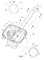
図1は、ハウジング2、外筒3および内筒4を備えるリニアアクチュエータ1を示す。リニアアクチュエータ1は、さらにリアマウント5およびモータハウジング6を備えている。内筒4の外端は、フロントマウント7を備えている。フロントマウント7およびリアマウント5は、リニアアクチュエータ1を組み込まれるべき構造体に固定するために使用される。
FIG. 1 shows a
図2は、リニアアクチュエータ1を示し、ここで、ハウジング2(モータハウジング6を含む)および外筒3は、アクチュエータの内部部品を示すために除去されている。リニアアクチュエータ1のモータハウジング6は、このように電動モータ8、制御プリント基板9およびリアマウント機構10を備える。変速機を介して、電動モータ8はアクチュエータの軸11を駆動する(図3〜7を参照)。軸ナット12は、軸11上をスライドし、内筒4との接続を形成している。これにより、軸ナット12は、スプラインブッシュ14を介して内筒4が静止しうる、肩部13を備える。前記軸ナットと前記内筒との連携の詳細な説明は、図3〜図5に関連して説明される。前記軸ナットと前期内筒との連携の他の実施形態は、図6および図7に関連して説明される。この実施形態では、前記変速機は、電動モータ8の駆動軸(図示略)に連続して配置されたウォームギア15を備える。ウォームギア15は、前記軸の軸17(図14参照)に固定されたウォームホイール16を駆動する。軸11の長手方向軸および回転軸は、ウォームホイール16の長手方向軸および回転軸と並行である。ウォームギア15の長さ方向軸と回転軸は、前記ウォームホイールの長手方向軸および回転軸とほぼ直角である。軸ナット12とスプラインブッシュ14はいずれも、外筒3の内部側の突起の列(図3および図10参照)と協働して、軸ナット12とスプラインブッシュ14の回転を防ぐガイドフィン46,47の列を備えている。軸11の回転方向に依存して、軸ナット12、内筒4およびフロントマウント7は、リアマウント5に対して内向きまたは外向きのいずれかに運ばれる。リアマウント5は、軸シャフト17が組み込まれたリアマウント機構10に含まれる。リアマウント機構10は、図12でより完全に記載されている。制御プリント基板9は、軸ナット12とともに電動モータ8の始動および停止のための終端機構を構成する、2つの終端スイッチ18,19を備えている。リニアアクチュエータ1が、張力を受ける場合、スプラインブッシュ14および内筒4は、軸ナット12から外れることが可能となり、互いに相対的に変位する(図3のC−C断面を示す図5を参照)。前記リニアアクチュエータが、圧縮を受ける場合、スプラインブッシュ14は、軸ナット12上を再び滑る(図3のC−C断面を示す図4を参照)。この機能は、機械的な圧搾保護と呼ばれている。リニアアクチュエータ1が、たとえばベッドの背面部分に関連して搭載された場合、前記リニアアクチュエータの内側への動きに対応して、この背面部分が下降中にある物体が前記背面部分と前記ベッドとの間に意図せず捕捉されると、スプラインブッシュ14が前記軸ナットの肩部13から外れたままで、前記リニアアクチュエータは、それ以上下方に前記背面部分を引くことができない。捕捉された前記物体が取り除かれると、スプラインブッシュ14および軸ナット12が再び相互接続され、リニアアクチュエータ1は、再び圧縮を受ける。
FIG. 2 shows a
図2、図3および図6を参照しつつ、前記終端機構について説明する。終端スイッチ18,19は、制御プリント基板9上に搭載されており、摺動要素21の突起20により作動および非作動させることができる。突起20は、軸ナット12が摺動要素21のストッパ23,24のいずれかにはまると、制御プリント基板9のプリント基板ガイド22内をスライドすることができる。これは、軸ナット12が前記リニアアクチュエータのストローク長の端に到達したときに発生する。なお、このストロークは、摺動要素21のストッパ23,24間の距離によっておおよそ与えられることに留意すべきである。軸ナット12(および内筒4、フロントマウント7)が、たとえばリアマウント5に向かう方向、すなわち内側に向かってに動くと、軸ナット12が、いくつかの箇所でストッパ23にはまり、摺動要素21がリアマウント5に向かわされる。突起20のこの移動により、終端スイッチ18が、電動モータ8が停止されるように作動され、軸11の回転が止まる。軸ナット12(および内筒4、フロントマウント7)が、フロントマウント7に向かう方向、すなわち外向き方向に移動したときに、対応する効果が得られる。軸ナット12がストッパ24に係合すると、摺動要素21リアマウント5とは反対方向に動かされる。これにより、突起20が終端スイッチ19を作動させ、電動モータ8が停止し、軸11の回転が停止する。前記リニアアクチュエータの制御は(図18および図19参照)、電動モータ8を再始動することを保証するが、終端スイッチ18,19の作動を起こした方向とは逆方向の一方向のみに回転する。軸ナット12が、電動モータ8の停止を起こした方向とは逆方向に移動すると、軸ナット12は、いくつかの箇所でストッパ23,24との係合から解放される。これと同時に、ばね25は、軸ナット12と同方向に摺動要素21を変位させる。したがって、終端スイッチ18,19が再び非作動の状態とされる。ばね25は、制御プリント基板9に関連して配置されており、摺動要素21によって構成されるばね脚部26と係合している。ばね25は、リニアアクチュエータ1の通常の使用時において終端スイッチ18,19が意図せず作動しないように、摺動要素21を静止位置に保持する。摺動要素21のストッパ23,24が軸ナット12と係合し、終端スイッチ18,19のいずれかが作動すると、ばね25は締められる。軸ナット12がストッパ23,24のいずれかとの係合を解除すると同時に、力がかけられたばね25は、摺動要素21を初期位置に戻す。なお、突起20は、摺動要素21がその静止位置にあるときに、終端スイッチ18,19が作動するように設計されている。したがって、終端スイッチ18,19の非作動は、電動モータ8を停止させる。図2、図3および図6に示す制御プリント基板9もまた、2つの終端スイッチ18,19に加えて、2つのリレー27およびプラグ28を備えている。終端スイッチ18,19のいずれかから非作動信号は、電動モータ8への電圧供給を中断し、または電動モータ8の短絡を引き起こすように、リレー27のいずれかに伝えられる。非作動とされた終端スイッチ18,19が再び作動すると、リレー27のいずれかを介して電動モータ8が始動する。制御プリント基板9のこの実施形態では、終端スイッチ18,19は、信号(信号送信機)の送信者としてのみ機能する。前記電気モータの電流は、このようにリレー27のみを介して流れる。リニアアクチュエータ1は、プラグ28を介して制御プリント基板9に接続されており、これは図18および図19に示すアクチュエータシステムの一部となる。
The termination mechanism will be described with reference to FIGS. 2, 3 and 6. The end switches 18 and 19 are mounted on the control printed
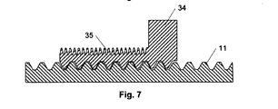
図6は、スプラインブッシュを備えない他の実施形態におけるリニアアクチュエータ1のサブコンポーネントの斜視図である。ここでは、軸ナット34(図7のD−D断面を参照)は、内筒(図示せず)の一端を固定することができるねじ部35を備える(図7のD−D断面参照)。この実施形態のリニアアクチュエータでは、前記内筒は、このように常に軸ナット34に追従する。上記のような圧搾を防止するために、前記アクチュエータは電気的な圧搾保護を備えることができる。これは、たとえばアクチュエータの電動モータの負荷を絶えず測定し、負荷が所定の閾値に達した場合、電動モータを中断することによって達成することができる。
FIG. 6 is a perspective view of subcomponents of the
図8および図9は、制御プリント基板の他の実施形態を示す。この制御プリント基板29は、2つの終端スイッチ30,31とリニアアクチュエータを接続するためのプラグ32とを備えている。制御プリント基板29の機能は、図2、図3および図6を参照して説明したとのと同様であるが、リレーを備えていない。つまりここでは、終端スイッチ30,31が電動モータ8の電流を通電させかつ遮断する。これらの終端スイッチ30,31は、電動モータ8の電流を通電しうるものとして設計されるべきである。
8 and 9 show another embodiment of the control printed circuit board. The control printed
図10は、外筒3およびコンソール37を備えたベースユニット36を示している。外筒3は、リニアアクチュエータ1の所望のストローク長に応じて異なる長さを有していてもよい。ベースユニット36は、1つのユニットとして設計されており、好ましくはプラスチック射出成形によって一体的に鋳造される。ベースユニットコンソール37は、電動モータ8と制御プリント基板9,29とを、突起20およびばね脚部26を備えた摺動要素21の部分に沿って搭載するために用意されている。前記ベースユニットの外筒3は、図示された実施形態においては略円筒状の断面を有するがさらに、ガイド38(A−A断面参照)を含んでおり、その中に摺動要素21が配置されている。軸ナット12と内筒4は、ベースユニットコンソール37とは反対側の前記ベースユニットの外筒3の開口37から内筒4が出られるように、前記ベースユニットの外筒3内に配置されている。ベースユニットの外筒3は、開口部39付近の外筒3の内部側に位置し、内筒4をガイド可能なガイド40(B−B断面参照)を備える。摺動要素21は、ストッパ23,24が外筒3内に配置された軸11に対面するように、向けられている。突起20と摺動要素21のばね脚部26は、前記ベースユニットの外筒3とベースユニットコンソール37の搭載面(図示略)との間の開口41を部分的に通過させることができる。電動モータ8を取り付けるために、ベースユニットコンソール37は、搭載孔42の列と軸孔43を備える。電動モータ8の駆動軸の延長上に装着されたウォームギア15は、このように軸孔43を通って導かれ、電動モータ8は、搭載孔42によってコンソール37に固定されている。ベースユニットコンソール37は、さらに、モータハウジング6に固定するためのねじ塔44の列を備えている。軸ナット12,34の回転を阻止するため、ベースユニットの外筒3の内部側には、軸ナット12,34の外周側のガイドフィン46の対応する列がその間をガイドされうる、突起45の列を含んでいる。リニアアクチュエータが機械的な圧搾保護を用いて構成されている場合、軸ナット12が協働するガイドフィン47を備えるのと同様に、前記外筒の突起45は、スプラインブッシュ14をガイドし回転を阻止するために用いられる。本明細書において、スプラインブッシュの語は、スプライン接続(図示略)として設計されたブッシュと、スプライン接続(スプラインブッシュ14)を備えないブッシュの両方を含む。これは、前記リニアアクチュエータは、回転に対して前記軸ナットと前記スプラインブッシュの両方を固定することなく構成することができるという事実による。この状況では、前記軸ナットと前記スプラインブッシュとの間の接続は、便宜上スプライン接続として構成することができる。
FIG. 10 shows the
図11は、外筒3の開口39(図10参照)への取り付けのために搭載面49が用意されたシールブッシュ48を示している。シールブッシュ48は、前記ベースユニットの外筒3と内筒4との間のリニアアクチュエータ1のシールとして機能する。したがって、シールブッシュ48はワッシャ50を含んでもよい。シールブッシュ48は、ワッシャ50がシールブッシュ48の統合部分とされた、二成分プラスチック成形部品であってもよい。同様に、ワッシャ(図示せず)が、搭載面49とシールブッシュ48との間に配置されてもよい。外筒3にシールブッシュ48を固定するためのスナップ接続を用いてもよい。したがって、ここでは、シールブッシュ48は、それぞれが突起(図示せず)を含むばね脚部51の列を備えて構成されている。前記シールブッシュが締結されている場合、ばね脚部51は、各々の突起が各ばね脚部ガイド52のストッパあるいは孔(図示略)に係合することにより、外筒3の端部の対応するばね脚部ガイド52に係合される。こうして、シールブッシュ48は、外筒3の端部に対して固定される。スナップ接続の代替手段としては、一つ以上のリベットまたはねじによる接続が用いられる。いずれの接続手段が使われているかにかかわらず、ワッシャ50は外筒3に実際に締結されている間に圧縮を受けるべきであり、そのような材料から作られ設計されてもよい。この圧縮の間に蓄積された力は、締結後に望ましいシーリングを確保する。シールブッシュ48は、内筒4がガイドされ得るガイド(図示せず)を含んでもよい。このガイドは、外筒3に統合される態様ですでに存在するガイド40を補足することが可能であり、また前記外筒が前記ガイドを備えない場合にその代替品となりうる。
FIG. 11 shows a
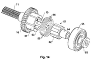
図12は、リアマウント5を備えるリアマウント機構10(図2も参照)を示している。以下においては、リアマウント機構10の機能は、図12、図13および図14を参照して説明される。図12に示すように、リアマウント機構10の外観は、リアマウントベース53およびリアマウントシェル54を備える。後者は、図13において省略されている。リアマウント機構10はさらに、軸受55を取り囲んでいる。軸17は、ブッシュ61を介して軸受55に搭載されている。ねじばね56は、ウォームホイール16の円筒状の肩部57に取り付けられている。軸ナット12および4が外側に移動するように軸11が回転するとき、ねじばね56は、その巻きと向きに起因して肩部57との係合が弱まり、このようにしてねじばね56と肩部57との摩擦が減少する。反対方向の回転、すなわち軸ナット12および内筒4が内側に移動するときには、ねじばね56は肩部57に締め付けられ、このようにしてねじばね56と肩部57との摩擦が増加する。これゆえ、電動モータ8は、軸ナット12と前記内筒とが内側に移動できるように、軸11を回転できるほどに、この摩擦に打ち勝つのに十分なトルクを発揮できるものでなければならない。ねじばね56は、軸11がセルフロックであることを確実にするために、このように設計されている。これにより、軸ナット12と前記内筒とは、リニアアクチュエータの負荷の結果として内側方向に意図せず移動することはない。すべての可動部がベースユニット36に取り付けられているときは、リアマウント機構10は、前記ベースユニット(図10参照)の開口58に固定されていることが好ましい。このように、リアマウント機構10は、軸受55が軸17の端部周辺に配置され、ねじばね56が肩部57周辺に配置されていることにより、開口58内に押し込まれることができる。リアマウント機構10は、ベースユニット36のねじ孔60を通してねじ塔59にねじを締結することにより、実際のベーユニット36に固定されている。リアマウント機構10およびベースユニット36は、リアマウント機構10をベースユニット36に固定するためのいくつかのねじ塔59といくつかのねじ孔60をそれぞれに備えることができる(図1参照)。セルフロックの軸11は、所望の位置に到達したときに、電動モータ8を短絡させることによって達成することができる。
FIG. 12 shows a rear mount mechanism 10 (see also FIG. 2) including the
図13は、どのように電動モータ8の軸がウォームギア15によって延長され、そしてそれがどのようにウォームホイール16と係合するかを示している。図14に示すように、ウォームホイール16は、歯62とともにブッシュ61を介して軸11との接続を確立している。ブッシュ61はD形状の断面を有する軸17に取り付けられている。歯62は、ウォームホイール16の対応する歯63に係合している。ブッシュ61は、さらに、軸受55が固定された肩部64を備える。ブッシュ61と軸受55が軸17から外れないようにするために、ディスク65が軸17の端部に固定されている。すべてのこれらの部分が軸17に取り付けられている場合、リアマウントベース53と、その後のリアマウントシェル54は、軸受55とばね56の周りに取り付けることができる。なお、このような取り付けに際し、ねじばね56の一端は、リアマウントベース53の凹部67に係合する巻線66を備える(図13参照)。
FIG. 13 shows how the shaft of the
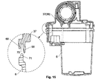
図15は、ベースユニットコンソール37とモータハウジング6との間のそれぞれの接合面の断面を示している。ベースユニットコンソール37は、その間に溝70が形成された後縁68と前縁69とを備える接合面を有している。モータハウジング6の接合面は、モータハウジング6の装着時に溝70内に導かれる凸部71を備える。後縁68は、前縁69に向かう方向に小さな巻線を持っており、これによってモータハウジング6の取付け時に凸部71が前縁69に対して前方に押される。このように、後縁68の協働面と凸部71とは、長く途切れない封止接触面を形成する。この封止を改善するため、モータハウジング6はベースユニット36よりも柔軟な材質から作られることが有利である。モータハウジング6の取付け時の後縁68が前縁69に対して凸部71を押すと、凸部71が変形される。亀裂の形成、またはたとえば衝撃力に起因する他の欠陥を回避するために、モータハウジング6は、角を丸くとるように設計されている。前記モータハウジングの柔軟な材料は、同様にこれらの不要な損害を回避することに貢献する。モータハウジング6とベースユニット36との間の封止をさらに改善するために、溝70は、好ましくはシリコーンからなるワッシャを備えることができる。
FIG. 15 shows a cross section of each joint surface between the
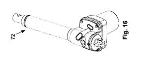
図16および図17は、2つの異なる実施形態におけるリニアアクチュエータ72,73を示している。図16のリニアアクチュエータ72は、このように短いストローク長を有し、比較的小さな設置長とされている。後者は、リアマウント5からフロントマウント7までの距離を表している(図1参照)。リニアアクチュエータ73は、異なるストローク長と設置長とを有する。このように異なる仕様のリニアアクチュエータ1,72,73を製造できるように、前記ベースユニットのためのプラスチック金型はモジュール方式であり、前記ベースユニットの外筒3の長さは異なる器具を挿入するという手段により変更可能である。同様に、ベースユニットコンソールを変更することができる。
16 and 17 show
図18および19は、それぞれアクチュエータシステムに接続されたリニアアクチュエータの回路図を示す。図18の回路図は、リニアアクチュエータ1、分配装置74(好ましくはマルチジャンクションボックスまたは分岐ケーブル)、電源装置75および操作パネル76を含む。同図に示すように、操作パネル76を操作することにより、分配装置74を介して電源装置75をリニアアクチュエータ1に供給電圧を送らせることによって、リニアアクチュエータ1は作動される。図19の回路図は、リニアアクチュエータ1、コントロールボックス77および操作パネル78を含む。この操作パネルを操作することにより、リニアアクチュエータ1に供給電圧を送るためにコントロールボックス77に信号が送られることによって、リニアアクチュエータ1は作動される。同図に示すように、電源は、コントロールボックス77に組み込まれている。複数のリニアアクチュエータ1と複数の操作パネル76,78等が、図示された各々の回路図に接続されてもよいことが直ちに理解される。さらに、接続されたリニアアクチュエータは、図16および図17に示されたタイプのものであってもよいことが理解される。
18 and 19 each show a circuit diagram of a linear actuator connected to the actuator system. The circuit diagram of FIG. 18 includes a
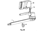
スペースへの配慮から、コントロールボックスをリニアアクチュエータとともに取り付けることが、多くの場合都合がよい。使用されるコントロールボックスはジェネリック型であり、したがって、複数の異なるタイプのリニアアクチュエータを有するアクチュエータシステムが使用され、リニアアクチュエータとコントロールボックスの物理的な相互接続を可能とするための中間部品とともにリニアアクチュエータが備えられることが必要となる場合がある。これは、図20、図21および図22の斜視図に示すリニアアクチュエータ1を用いても同様である。ここでは、リニアアクチュエータ1には、コントロールボックスボックス80との相互接続のためのアダプタとして中間部品79が備わっている。さらに、相互接続を強化するために、コントロールボックス80の両側に固定されるU字形のクリップ81は、ベースユニットの外筒(参照されていない)の周りに導かれる。別の実施形態では(図示せず)、コントロールボックスは、たとえばクリップ手段によってリニアアクチュエータ上に直接装着することができるように設計されている。
In consideration of space, it is often convenient to attach the control box together with a linear actuator. The control box used is generic and therefore an actuator system with several different types of linear actuators is used, and linear actuators with intermediate parts to allow physical interconnection of the linear actuators and the control box May need to be provided. This is the same even when the
Claims (12)
少なくとも2つの部分からなるハウジング(2)と、
電動モータ(8)と、
前記電動モータ(8)を収容し、前記ハウジング(2)の第1部分を構成するモータハウジング(6)と、
変速機(15,16)と、
前記変速機(15,16)を介して前記電動モータ(8)によって駆動される軸(11)と、
前記軸(11)に対して回転しないように固定された軸ナット(12,34)と、
前記軸(11)をはめ込むための軸受(55)と、
前記外筒(3)に入れ子状に伸縮自在にはめ込まれ、一端が前記軸ナット(12,34)に接続された、内筒(4)と、
前記内筒(4)の他端に位置するフロントマウント(7)と、
前記コンソール(37)に固定されたリアマウント(5)と、
を備えたリニアアクチュエータ(1)であって、
前記外筒(3)の全体と前記コンソール(37)とは、ベースユニット(36)を構成する一体的なユニットであることを特徴とする、リニアアクチュエータ(1)。 An outer cylinder (3) and a console (37) fixed to each other;
A housing (2) comprising at least two parts;
An electric motor (8);
A motor housing (6) that houses the electric motor (8) and forms a first part of the housing (2);
A transmission (15, 16);
A shaft (11) driven by the electric motor (8) via the transmission (15, 16);
Shaft nuts (12, 34) fixed so as not to rotate with respect to the shaft (11);
A bearing (55) for fitting the shaft (11);
An inner cylinder (4) which is telescopically fitted into the outer cylinder (3) and has one end connected to the shaft nut (12, 34);
A front mount (7) located at the other end of the inner cylinder (4);
A rear mount (5) fixed to the console (37);
A linear actuator (1) comprising:
The linear actuator (1), wherein the entire outer cylinder (3) and the console (37) are an integral unit constituting a base unit (36).
Applications Claiming Priority (3)
| Application Number | Priority Date | Filing Date | Title |
|---|---|---|---|
| DKPA201001173 | 2010-12-21 | ||
| DKPA201001173 | 2010-12-21 | ||
| PCT/DK2011/000152 WO2012083951A1 (en) | 2010-12-21 | 2011-12-21 | Linear actuator |
Publications (2)
| Publication Number | Publication Date |
|---|---|
| JP2014501892A JP2014501892A (en) | 2014-01-23 |
| JP6006232B2 true JP6006232B2 (en) | 2016-10-12 |
Family
ID=45855434
Family Applications (1)
| Application Number | Title | Priority Date | Filing Date |
|---|---|---|---|
| JP2013545049A Active JP6006232B2 (en) | 2010-12-21 | 2011-12-21 | Linear actuator |
Country Status (10)
| Country | Link |
|---|---|
| US (1) | US10516318B2 (en) |
| EP (1) | EP2655935B1 (en) |
| JP (1) | JP6006232B2 (en) |
| CN (1) | CN103270342B (en) |
| BR (1) | BR112013014714A2 (en) |
| DK (1) | DK2655935T3 (en) |
| ES (1) | ES2532216T3 (en) |
| PL (1) | PL2655935T3 (en) |
| RU (1) | RU2582744C2 (en) |
| WO (1) | WO2012083951A1 (en) |
Cited By (1)
| Publication number | Priority date | Publication date | Assignee | Title |
|---|---|---|---|---|
| JP2019127205A (en) * | 2018-01-26 | 2019-08-01 | 新明和工業株式会社 | Lid opening and closing device of work vehicle |
Families Citing this family (40)
| Publication number | Priority date | Publication date | Assignee | Title |
|---|---|---|---|---|
| DE102009015690A1 (en) * | 2009-03-31 | 2010-10-07 | Logicdata Electronic & Software Entwicklungs Gmbh | Linear drive and table with linear drive |
| US9295598B2 (en) * | 2011-12-09 | 2016-03-29 | Stryker Corporation | Patient support backrest release and actuator assembly |
| JP5675721B2 (en) * | 2012-07-18 | 2015-02-25 | 株式会社ミツバ | Electric bed linear actuator |
| WO2014085807A2 (en) * | 2012-11-30 | 2014-06-05 | D-Box Technologies Inc. | Linear actuator for motion simulator |
| JP6450322B2 (en) | 2012-11-30 | 2019-01-09 | ディー−ボックス テクノロジーズ インコーポレイテッド | Linear actuator for motion simulator |
| CN104884824B (en) * | 2012-11-30 | 2017-08-08 | 迪宝克技术公司 | Linear actuators for motion simulator |
| US9334936B2 (en) * | 2013-04-18 | 2016-05-10 | Tolomatic, Inc. | High stiffness thrust component for linear actuator |
| DE102013106388B3 (en) * | 2013-06-19 | 2014-10-09 | Limoss Gmbh & Co. Kg | Adjustment mechanism for adjusting movable furniture parts |
| US9303741B2 (en) * | 2013-12-06 | 2016-04-05 | Kan Cui | Linear-to-rotary actuator |
| EP3113906B1 (en) * | 2014-03-04 | 2018-03-21 | Innse-Berardi S.p.A. | Machine tool with onboard motor |
| DK3175145T3 (en) * | 2014-07-29 | 2019-01-07 | Linak As | LINEAR ACTUATOR |
| CN105757205B (en) * | 2014-11-12 | 2017-10-27 | 力纳克传动系统(深圳)有限公司 | linear actuator system |
| CN105752876B (en) * | 2014-11-12 | 2017-12-22 | 力纳克传动系统(深圳)有限公司 | linear actuator system |
| CN105715754B (en) * | 2014-11-12 | 2017-10-31 | 力纳克传动系统(深圳)有限公司 | linear actuator system |
| ITUB20152649A1 (en) * | 2015-07-30 | 2017-01-30 | Innovative Eng Search Ltd | ELECTRIC PISTON |
| DE202016106361U1 (en) * | 2016-11-14 | 2018-02-15 | Dewertokin Gmbh | linear actuator |
| CN106595213B (en) * | 2017-01-24 | 2022-05-31 | 无锡晶美精密滑轨有限公司 | Synchronous belt buckle |
| GB2560880A (en) * | 2017-03-09 | 2018-10-03 | Sound Leisure Ltd | An apparatus for changing a record, a method of loading a record and a method of changing the side of a record to be played |
| US11060592B2 (en) | 2017-06-28 | 2021-07-13 | Linak A/S | Linear actuator |
| WO2019001652A1 (en) * | 2017-06-28 | 2019-01-03 | Linak A/S | Linear actuator |
| WO2019001655A1 (en) * | 2017-06-28 | 2019-01-03 | Linak A/S | Linear actuator |
| JP2020532254A (en) | 2017-08-23 | 2020-11-05 | リナック エー/エス | Linear actuator with end stop switch |
| FR3071784B1 (en) * | 2017-09-29 | 2019-10-18 | Faurecia Sieges D'automobile | SCREW ADJUSTMENT MECHANISM, SLIDE COMPRISING SUCH AN ADJUSTING MECHANISM AND SEAT COMPRISING SUCH A SLIDER. |
| CN107707070A (en) * | 2017-10-09 | 2018-02-16 | 中国船舶重工集团公司第七0四研究所 | A kind of servo electric jar of oil-free grease lubrication |
| WO2019091524A1 (en) * | 2017-11-12 | 2019-05-16 | Linak A/S | A linear actuator |
| CN107733147B (en) * | 2017-11-20 | 2020-10-20 | 芜湖得瑞自动化技术有限公司 | Electric cylinder |
| WO2019133600A1 (en) * | 2017-12-28 | 2019-07-04 | Kelsey-Hayes Company | Electric actuator assembly for a drum brake assembly |
| TR201806877A2 (en) * | 2018-05-15 | 2018-06-21 | Ikizler Kalip Pres Sanayi Ve Ticaret Ltd Sirketi | Smart, Monoblock And Compact Motor Gear Reducer |
| WO2019218154A1 (en) * | 2018-05-15 | 2019-11-21 | 炼马机电(东莞)有限公司 | Linear driver |
| TWM582549U (en) * | 2018-07-06 | 2019-08-21 | 第一傳動科技股份有限公司 | Linear actuator with cushion mechanism |
| CN208835918U (en) * | 2018-09-04 | 2019-05-07 | 江苏雷利电机股份有限公司 | Electric machine |
| CN109510429B (en) * | 2018-10-27 | 2024-04-09 | 浙江捷昌线性驱动科技股份有限公司 | Linear actuator |
| US11925996B2 (en) | 2018-11-27 | 2024-03-12 | Tolomatic, Inc. | Integrated guide linear actuator system |
| JP2022523438A (en) * | 2019-03-13 | 2022-04-22 | リナック エー/エス | Linear actuator |
| DE202019103356U1 (en) * | 2019-06-14 | 2020-09-15 | Dewertokin Gmbh | Suppressed linear drive |
| US11754157B2 (en) | 2020-05-20 | 2023-09-12 | Tolomatic, Inc. | Integrated motor linear actuator |
| USD944302S1 (en) * | 2020-05-21 | 2022-02-22 | Linak A/S | Linear actuator |
| TWD215724S (en) * | 2020-05-21 | 2021-12-01 | 丹麥商林納克公司 | Linear actuator |
| TWD215723S (en) * | 2020-05-21 | 2021-12-01 | 丹麥商林納克公司 | Linear actuator |
| CN113088880B (en) * | 2021-06-08 | 2021-08-27 | 上海陛通半导体能源科技股份有限公司 | Telescopic driving assembly structure and semiconductor device |
Family Cites Families (25)
| Publication number | Priority date | Publication date | Assignee | Title |
|---|---|---|---|---|
| US3909759A (en) * | 1974-04-08 | 1975-09-30 | Gen Electric | Bushing well for instrument transformer and transformers including such well |
| DE3332259A1 (en) * | 1983-09-07 | 1985-03-28 | Danfoss A/S, Nordborg | REFRIGERATOR COMPRESSORS |
| US4858481A (en) * | 1985-05-13 | 1989-08-22 | Brunswick Valve & Control, Inc. | Position controlled linear actuator |
| DK155291A (en) | 1991-09-04 | 1993-03-05 | Linak As | ACTUATOR |
| DE9404383U1 (en) | 1994-03-17 | 1994-05-05 | Dewert Antriebs Systemtech | Electromotive adjustment drive |
| US6259175B1 (en) * | 1999-11-18 | 2001-07-10 | Dana Corporation | Linear actuator |
| DE60112597T2 (en) * | 2000-10-03 | 2006-06-08 | Linak A/S | LINEAR ACTUATOR |
| KR100445434B1 (en) * | 2002-07-10 | 2004-08-21 | 삼성에스디아이 주식회사 | Positive active material composition for lithium sulfur battery and lithium sulfur battery fabricated using same |
| EP1420504B1 (en) | 2002-11-15 | 2012-06-13 | Ab Skf | Limit switch for a linear drive |
| DE202004002254U1 (en) * | 2003-02-13 | 2004-04-15 | Dewert Antriebs- Und Systemtechnik Gmbh & Co Kg | Electromotive linear drive |
| DE102004023243A1 (en) | 2004-05-07 | 2005-12-01 | Dewert Antriebs- Und Systemtechnik Gmbh & Co Kg | Electric motor linear drive for furniture such as slatted frame bed has motor reduction gear and spindle with functional connected parts being of one piece plastic |
| US8181546B2 (en) * | 2004-10-15 | 2012-05-22 | Linak A/S | Linear actuator |
| RU2297563C2 (en) * | 2004-11-24 | 2007-04-20 | Вячеслав Васильевич Козырев | Electric drive on the base of a gear with long thread rolls |
| US8850479B2 (en) * | 2005-03-02 | 2014-09-30 | Panasonic Corporation | Distribution device and reception device |
| JP4699799B2 (en) * | 2005-04-26 | 2011-06-15 | 株式会社 五十嵐電機製作所 | Electric actuator |
| GB2426556B (en) * | 2005-05-17 | 2010-06-09 | Thomas Industries Inc | Pump improvements |
| JP2009506807A (en) * | 2005-09-02 | 2009-02-19 | リナック エー/エス | Actuator |
| CN101258663B (en) | 2005-09-09 | 2011-11-09 | 利纳克有限公司 | Actuator with electrical equipment enclosed in a separate enclosure made of a fire resistant |
| DE202006018505U1 (en) * | 2006-12-05 | 2008-04-17 | Dewert Antriebs- Und Systemtechnik Gmbh | Electromotive linear drive |
| AU2007341779B2 (en) * | 2006-12-31 | 2012-09-06 | Linak A/S | Actuator system |
| DE102007006249A1 (en) * | 2007-02-08 | 2008-08-14 | Robert Bosch Gmbh | linear module |
| US7533591B2 (en) * | 2007-03-03 | 2009-05-19 | T-Motion Technology Co., Ltd. | Fast-releasing controlling device of actuator for electric sickbed |
| US8297142B2 (en) * | 2007-03-22 | 2012-10-30 | Nsk Ltd. | Actuator |
| TWM345334U (en) * | 2008-06-02 | 2008-11-21 | Moteck Electric Corp | Actuator shell structure |
| US20100206101A1 (en) * | 2009-02-19 | 2010-08-19 | Hiwin Mikrosystem Corp. | Linear actuator |
-
2011
- 2011-12-21 DK DK11826170T patent/DK2655935T3/en active
- 2011-12-21 RU RU2013132648/11A patent/RU2582744C2/en not_active IP Right Cessation
- 2011-12-21 ES ES11826170.0T patent/ES2532216T3/en active Active
- 2011-12-21 PL PL11826170T patent/PL2655935T3/en unknown
- 2011-12-21 US US13/996,312 patent/US10516318B2/en not_active Expired - Fee Related
- 2011-12-21 BR BR112013014714A patent/BR112013014714A2/en not_active IP Right Cessation
- 2011-12-21 EP EP11826170.0A patent/EP2655935B1/en not_active Revoked
- 2011-12-21 JP JP2013545049A patent/JP6006232B2/en active Active
- 2011-12-21 WO PCT/DK2011/000152 patent/WO2012083951A1/en active Application Filing
- 2011-12-21 CN CN201180061643.1A patent/CN103270342B/en not_active Expired - Fee Related
Cited By (1)
| Publication number | Priority date | Publication date | Assignee | Title |
|---|---|---|---|---|
| JP2019127205A (en) * | 2018-01-26 | 2019-08-01 | 新明和工業株式会社 | Lid opening and closing device of work vehicle |
Also Published As
| Publication number | Publication date |
|---|---|
| CN103270342B (en) | 2017-02-08 |
| ES2532216T3 (en) | 2015-03-25 |
| RU2582744C2 (en) | 2016-04-27 |
| US10516318B2 (en) | 2019-12-24 |
| EP2655935A1 (en) | 2013-10-30 |
| PL2655935T3 (en) | 2015-07-31 |
| BR112013014714A2 (en) | 2016-10-04 |
| DK2655935T3 (en) | 2015-03-09 |
| EP2655935B1 (en) | 2015-01-28 |
| JP2014501892A (en) | 2014-01-23 |
| RU2013132648A (en) | 2015-01-27 |
| CN103270342A (en) | 2013-08-28 |
| WO2012083951A1 (en) | 2012-06-28 |
| US20130285494A1 (en) | 2013-10-31 |
Similar Documents
| Publication | Publication Date | Title |
|---|---|---|
| JP6006232B2 (en) | Linear actuator | |
| US8294310B2 (en) | Motor with reduction gear mechanism | |
| US8156605B2 (en) | Drive device | |
| JP5595100B2 (en) | Motor equipment | |
| JP4556935B2 (en) | Starter | |
| KR20070109819A (en) | Wiper motor and wiper apparatus | |
| KR101810896B1 (en) | Electric parking brake in vehicle | |
| KR100955459B1 (en) | Crossing gate for vehicles with backlash preclusion | |
| RU2010133116A (en) | DRIVE UNIT | |
| JP6269987B2 (en) | Actuating unit for automobile door lock and manufacturing method | |
| JP2001065215A (en) | Opener actuator for fuel filler lid | |
| JP7180517B2 (en) | rotary actuator | |
| US11888380B2 (en) | Linear actuator | |
| CN113726090B (en) | Motor driving structure and motor driving device | |
| CN113357335A (en) | Electric inhaul cable driving mechanism with self-return function | |
| ITMI972678A1 (en) | STARTER MOTOR PARTICULARLY TO START AN INTERNAL COMBUSTION ENGINE | |
| JP4111053B2 (en) | Starter | |
| JP2011033076A (en) | Wiper motor | |
| JP3773995B2 (en) | Actuator | |
| CN217381496U (en) | Electric inhaul cable driving mechanism with self-return function | |
| JP2010281391A (en) | Linear actuator | |
| CN216277401U (en) | Vehicle door lock actuator | |
| CN218283990U (en) | Electric chain saw with braking structure | |
| US11231094B2 (en) | Stroke-limiting control assembly and operating method thereof | |
| JP7457629B2 (en) | Motor device |
Legal Events
| Date | Code | Title | Description |
|---|---|---|---|
| A621 | Written request for application examination |
Free format text: JAPANESE INTERMEDIATE CODE: A621 Effective date: 20141204 |
|
| A977 | Report on retrieval |
Free format text: JAPANESE INTERMEDIATE CODE: A971007 Effective date: 20150928 |
|
| A131 | Notification of reasons for refusal |
Free format text: JAPANESE INTERMEDIATE CODE: A131 Effective date: 20150929 |
|
| A601 | Written request for extension of time |
Free format text: JAPANESE INTERMEDIATE CODE: A601 Effective date: 20151224 |
|
| A521 | Request for written amendment filed |
Free format text: JAPANESE INTERMEDIATE CODE: A523 Effective date: 20160121 |
|
| A131 | Notification of reasons for refusal |
Free format text: JAPANESE INTERMEDIATE CODE: A131 Effective date: 20160628 |
|
| A521 | Request for written amendment filed |
Free format text: JAPANESE INTERMEDIATE CODE: A523 Effective date: 20160629 |
|
| TRDD | Decision of grant or rejection written | ||
| A01 | Written decision to grant a patent or to grant a registration (utility model) |
Free format text: JAPANESE INTERMEDIATE CODE: A01 Effective date: 20160906 |
|
| A61 | First payment of annual fees (during grant procedure) |
Free format text: JAPANESE INTERMEDIATE CODE: A61 Effective date: 20160908 |
|
| R150 | Certificate of patent or registration of utility model |
Ref document number: 6006232 Country of ref document: JP Free format text: JAPANESE INTERMEDIATE CODE: R150 |
|
| R250 | Receipt of annual fees |
Free format text: JAPANESE INTERMEDIATE CODE: R250 |
|
| R250 | Receipt of annual fees |
Free format text: JAPANESE INTERMEDIATE CODE: R250 |
|
| R250 | Receipt of annual fees |
Free format text: JAPANESE INTERMEDIATE CODE: R250 |
|
| R250 | Receipt of annual fees |
Free format text: JAPANESE INTERMEDIATE CODE: R250 |