JP6005860B2 - Thermodynamic equilibrium of combined heat and mass exchange equipment. - Google Patents
Thermodynamic equilibrium of combined heat and mass exchange equipment. Download PDFInfo
- Publication number
- JP6005860B2 JP6005860B2 JP2015523110A JP2015523110A JP6005860B2 JP 6005860 B2 JP6005860 B2 JP 6005860B2 JP 2015523110 A JP2015523110 A JP 2015523110A JP 2015523110 A JP2015523110 A JP 2015523110A JP 6005860 B2 JP6005860 B2 JP 6005860B2
- Authority
- JP
- Japan
- Prior art keywords
- carrier gas
- gas mixture
- liquid composition
- dehumidifier
- humidifier
- Prior art date
- Legal status (The legal status is an assumption and is not a legal conclusion. Google has not performed a legal analysis and makes no representation as to the accuracy of the status listed.)
- Active
Links
Images


Classifications
-
- B—PERFORMING OPERATIONS; TRANSPORTING
- B01—PHYSICAL OR CHEMICAL PROCESSES OR APPARATUS IN GENERAL
- B01D—SEPARATION
- B01D1/00—Evaporating
-
- F—MECHANICAL ENGINEERING; LIGHTING; HEATING; WEAPONS; BLASTING
- F15—FLUID-PRESSURE ACTUATORS; HYDRAULICS OR PNEUMATICS IN GENERAL
- F15D—FLUID DYNAMICS, i.e. METHODS OR MEANS FOR INFLUENCING THE FLOW OF GASES OR LIQUIDS
- F15D1/00—Influencing flow of fluids
-
- B—PERFORMING OPERATIONS; TRANSPORTING
- B01—PHYSICAL OR CHEMICAL PROCESSES OR APPARATUS IN GENERAL
- B01D—SEPARATION
- B01D1/00—Evaporating
- B01D1/0011—Heating features
- B01D1/0058—Use of waste energy from other processes or sources, e.g. combustion gas
-
- B—PERFORMING OPERATIONS; TRANSPORTING
- B01—PHYSICAL OR CHEMICAL PROCESSES OR APPARATUS IN GENERAL
- B01D—SEPARATION
- B01D1/00—Evaporating
- B01D1/0082—Regulation; Control
-
- B—PERFORMING OPERATIONS; TRANSPORTING
- B01—PHYSICAL OR CHEMICAL PROCESSES OR APPARATUS IN GENERAL
- B01D—SEPARATION
- B01D1/00—Evaporating
- B01D1/14—Evaporating with heated gases or vapours or liquids in contact with the liquid
-
- B—PERFORMING OPERATIONS; TRANSPORTING
- B01—PHYSICAL OR CHEMICAL PROCESSES OR APPARATUS IN GENERAL
- B01D—SEPARATION
- B01D5/00—Condensation of vapours; Recovering volatile solvents by condensation
- B01D5/0003—Condensation of vapours; Recovering volatile solvents by condensation by using heat-exchange surfaces for indirect contact between gases or vapours and the cooling medium
- B01D5/0006—Coils or serpentines
-
- B—PERFORMING OPERATIONS; TRANSPORTING
- B01—PHYSICAL OR CHEMICAL PROCESSES OR APPARATUS IN GENERAL
- B01D—SEPARATION
- B01D5/00—Condensation of vapours; Recovering volatile solvents by condensation
- B01D5/0033—Other features
- B01D5/0039—Recuperation of heat, e.g. use of heat pump(s), compression
-
- B—PERFORMING OPERATIONS; TRANSPORTING
- B01—PHYSICAL OR CHEMICAL PROCESSES OR APPARATUS IN GENERAL
- B01D—SEPARATION
- B01D5/00—Condensation of vapours; Recovering volatile solvents by condensation
- B01D5/0033—Other features
- B01D5/0045—Vacuum condensation
-
- B—PERFORMING OPERATIONS; TRANSPORTING
- B01—PHYSICAL OR CHEMICAL PROCESSES OR APPARATUS IN GENERAL
- B01D—SEPARATION
- B01D5/00—Condensation of vapours; Recovering volatile solvents by condensation
- B01D5/0033—Other features
- B01D5/0051—Regulation processes; Control systems, e.g. valves
-
- B—PERFORMING OPERATIONS; TRANSPORTING
- B01—PHYSICAL OR CHEMICAL PROCESSES OR APPARATUS IN GENERAL
- B01D—SEPARATION
- B01D5/00—Condensation of vapours; Recovering volatile solvents by condensation
- B01D5/0057—Condensation of vapours; Recovering volatile solvents by condensation in combination with other processes
- B01D5/006—Condensation of vapours; Recovering volatile solvents by condensation in combination with other processes with evaporation or distillation
-
- C—CHEMISTRY; METALLURGY
- C02—TREATMENT OF WATER, WASTE WATER, SEWAGE, OR SLUDGE
- C02F—TREATMENT OF WATER, WASTE WATER, SEWAGE, OR SLUDGE
- C02F1/00—Treatment of water, waste water, or sewage
- C02F1/02—Treatment of water, waste water, or sewage by heating
- C02F1/04—Treatment of water, waste water, or sewage by heating by distillation or evaporation
- C02F1/048—Purification of waste water by evaporation
-
- C—CHEMISTRY; METALLURGY
- C02—TREATMENT OF WATER, WASTE WATER, SEWAGE, OR SLUDGE
- C02F—TREATMENT OF WATER, WASTE WATER, SEWAGE, OR SLUDGE
- C02F1/00—Treatment of water, waste water, or sewage
- C02F1/02—Treatment of water, waste water, or sewage by heating
- C02F1/04—Treatment of water, waste water, or sewage by heating by distillation or evaporation
- C02F1/10—Treatment of water, waste water, or sewage by heating by distillation or evaporation by direct contact with a particulate solid or with a fluid, as a heat transfer medium
- C02F1/12—Spray evaporation
-
- C—CHEMISTRY; METALLURGY
- C02—TREATMENT OF WATER, WASTE WATER, SEWAGE, OR SLUDGE
- C02F—TREATMENT OF WATER, WASTE WATER, SEWAGE, OR SLUDGE
- C02F1/00—Treatment of water, waste water, or sewage
- C02F1/02—Treatment of water, waste water, or sewage by heating
- C02F1/04—Treatment of water, waste water, or sewage by heating by distillation or evaporation
- C02F1/14—Treatment of water, waste water, or sewage by heating by distillation or evaporation using solar energy
-
- C—CHEMISTRY; METALLURGY
- C02—TREATMENT OF WATER, WASTE WATER, SEWAGE, OR SLUDGE
- C02F—TREATMENT OF WATER, WASTE WATER, SEWAGE, OR SLUDGE
- C02F1/00—Treatment of water, waste water, or sewage
- C02F1/02—Treatment of water, waste water, or sewage by heating
- C02F1/04—Treatment of water, waste water, or sewage by heating by distillation or evaporation
- C02F1/16—Treatment of water, waste water, or sewage by heating by distillation or evaporation using waste heat from other processes
-
- C—CHEMISTRY; METALLURGY
- C02—TREATMENT OF WATER, WASTE WATER, SEWAGE, OR SLUDGE
- C02F—TREATMENT OF WATER, WASTE WATER, SEWAGE, OR SLUDGE
- C02F2103/00—Nature of the water, waste water, sewage or sludge to be treated
- C02F2103/08—Seawater, e.g. for desalination
-
- C—CHEMISTRY; METALLURGY
- C02—TREATMENT OF WATER, WASTE WATER, SEWAGE, OR SLUDGE
- C02F—TREATMENT OF WATER, WASTE WATER, SEWAGE, OR SLUDGE
- C02F2209/00—Controlling or monitoring parameters in water treatment
- C02F2209/02—Temperature
-
- C—CHEMISTRY; METALLURGY
- C02—TREATMENT OF WATER, WASTE WATER, SEWAGE, OR SLUDGE
- C02F—TREATMENT OF WATER, WASTE WATER, SEWAGE, OR SLUDGE
- C02F2303/00—Specific treatment goals
- C02F2303/22—Eliminating or preventing deposits, scale removal, scale prevention
-
- Y—GENERAL TAGGING OF NEW TECHNOLOGICAL DEVELOPMENTS; GENERAL TAGGING OF CROSS-SECTIONAL TECHNOLOGIES SPANNING OVER SEVERAL SECTIONS OF THE IPC; TECHNICAL SUBJECTS COVERED BY FORMER USPC CROSS-REFERENCE ART COLLECTIONS [XRACs] AND DIGESTS
- Y02—TECHNOLOGIES OR APPLICATIONS FOR MITIGATION OR ADAPTATION AGAINST CLIMATE CHANGE
- Y02A—TECHNOLOGIES FOR ADAPTATION TO CLIMATE CHANGE
- Y02A20/00—Water conservation; Efficient water supply; Efficient water use
- Y02A20/20—Controlling water pollution; Waste water treatment
- Y02A20/208—Off-grid powered water treatment
- Y02A20/212—Solar-powered wastewater sewage treatment, e.g. spray evaporation
-
- Y—GENERAL TAGGING OF NEW TECHNOLOGICAL DEVELOPMENTS; GENERAL TAGGING OF CROSS-SECTIONAL TECHNOLOGIES SPANNING OVER SEVERAL SECTIONS OF THE IPC; TECHNICAL SUBJECTS COVERED BY FORMER USPC CROSS-REFERENCE ART COLLECTIONS [XRACs] AND DIGESTS
- Y02—TECHNOLOGIES OR APPLICATIONS FOR MITIGATION OR ADAPTATION AGAINST CLIMATE CHANGE
- Y02W—CLIMATE CHANGE MITIGATION TECHNOLOGIES RELATED TO WASTEWATER TREATMENT OR WASTE MANAGEMENT
- Y02W10/00—Technologies for wastewater treatment
- Y02W10/30—Wastewater or sewage treatment systems using renewable energies
- Y02W10/37—Wastewater or sewage treatment systems using renewable energies using solar energy
-
- Y—GENERAL TAGGING OF NEW TECHNOLOGICAL DEVELOPMENTS; GENERAL TAGGING OF CROSS-SECTIONAL TECHNOLOGIES SPANNING OVER SEVERAL SECTIONS OF THE IPC; TECHNICAL SUBJECTS COVERED BY FORMER USPC CROSS-REFERENCE ART COLLECTIONS [XRACs] AND DIGESTS
- Y10—TECHNICAL SUBJECTS COVERED BY FORMER USPC
- Y10T—TECHNICAL SUBJECTS COVERED BY FORMER US CLASSIFICATION
- Y10T137/00—Fluid handling
- Y10T137/206—Flow affected by fluid contact, energy field or coanda effect [e.g., pure fluid device or system]
- Y10T137/2076—Utilizing diverse fluids
Description
今世紀において、淡水の欠乏は、人類における地球的関心事として、エネルギーの欠乏を凌駕するであろう。そして、この2つの問題は、「エコノミスト(The Economist)」誌の2010年5月20日号の「水に関する特別報告(Special Report on Water)」に解説されているように不可避的に関連している。淡水は、人間および他の生命体の最も基本的な必要物の1つである。人間は、1人当たり1日最少約2リットルの水を必要とする。また、世界は、農業および工業分野からの巨大な淡水需要に直面している。 In this century, the lack of fresh water will surpass the lack of energy as a global concern for mankind. These two problems are inevitably related as described in “Special Report on Water” of the May 20, 2010 issue of “The Economist” magazine. Yes. Fresh water is one of the most basic needs of humans and other life forms. Humans need a minimum of about 2 liters of water per person per day. The world is also facing huge freshwater demand from the agricultural and industrial sectors.
水の供給が不十分であることによって生じる弊害は特に深刻である。淡水の欠乏は、飢饉、疫病、死、追い込まれた大量移民、地域間の闘争/戦争、および生態系の崩壊を含む多様な危機をもたらす可能性がある。淡水の必要性の重要さ、および欠乏の広範な結果にも拘らず、淡水の供給は特に制限されている。地球上の水の97.5%は塩水であり、残りの部分の約70%は(殆ど氷床および氷河の)氷として固定され、地球上のすべての水のごく僅かな部分しか、利用可能な淡水(非塩水)としては残されていない。 The adverse effects caused by insufficient water supply are particularly serious. Freshwater deficiencies can result in a variety of crises including famine, plague, death, driven mass migration, interregional struggles / wars, and ecosystem disruptions. Despite the importance of the need for fresh water and the widespread consequences of deficiencies, the supply of fresh water is particularly limited. 97.5% of the earth's water is salt water, and about 70% of the rest is fixed as ice (mostly ice sheets and glaciers) and only a small fraction of all water on the earth is available It is not left as fresh water (non-salt water).
さらに、地球の利用可能な淡水は均等に分布していない。例えば、インドや中国のような過密人口の国々の多くの地域は供給不足に見舞われている。さらにまた、多くの場合、淡水の供給は季節的に一貫していない。その一方で、淡水に対する需要は全世界にわたって強化されている。貯水池は干上がりつつあり、帯水層は低下しつつあり、河川は乾燥しつつあり、氷河および氷床は後退しつつある。人口の増加は需要を増大させ、農業の変化および工業化の増進も同様である。気候の変化はさらなる脅威を多くの地域にもたらしている。その結果、水の欠乏に直面している人口は増大している。しかし、自然に生成される淡水は、通常、地域的な河川流域に限定されており、水の輸送は、費用が掛かりかつエネルギー消費型である。 Furthermore, the available fresh water on the earth is not evenly distributed. For example, many regions of overpopulated countries such as India and China are under supply. Furthermore, in many cases, the supply of fresh water is not seasonally consistent. On the other hand, demand for fresh water is increasing worldwide. Reservoirs are drying up, aquifers are falling, rivers are drying, glaciers and ice sheets are retreating. Population increases demand, as do agricultural changes and industrialization. Climate change poses additional threats to many regions. As a result, the population facing water scarcity is increasing. However, naturally produced fresh water is usually limited to regional river basins, and water transport is costly and energy consuming.
一方、海水から(あるいは比率は低いが鹹水から)淡水を生産する既存の多くのプロセスは大量のエネルギーを必要とする。逆浸透(reverse osmosis:RO)は、現在、最も主要な脱塩技術である。大型プラントでは、必要な比電力量は、理論的な最小値が約1kWh/m3であるのに比べて、30%回収で4kWh/m3程度に低くすることが可能であるが、小型のRO装置(例えば舶用装置)の効率はこれより低い。 On the other hand, many existing processes that produce fresh water from seawater (or from a low percentage of flooded water) require large amounts of energy. Reverse osmosis (RO) is currently the most major desalination technique. In large plants, the required specific power can be reduced to about 4 kWh / m 3 with 30% recovery compared to the theoretical minimum of about 1 kWh / m 3 . The efficiency of RO devices (eg marine equipment) is lower.
他の既存の海水脱塩システムとして、熱エネルギーベースの多段フラッシュ(thermal−energy−based multi−stage flash:MSF)蒸留法および多重効用蒸留(multi−effect distillation:MED)法が含まれるが、この両者は、エネルギー大量消費型であると共に大型資本を必要とするシステムである。しかし、MSFおよびMEDシステムにおいては、ブラインの最高温度と、入力熱の最高温度とは、硫酸カルシウムの沈殿を避けるために制限される。硫酸カルシウムが沈殿すると、熱伝達機器に硬いスケールが形成される。 Other existing seawater desalination systems include thermal-energy-based multi-stage flash (MSF) distillation and multi-effect distillation (MED) methods. Both systems are energy intensive and require large capital. However, in MSF and MED systems, the maximum brine temperature and the maximum input heat are limited to avoid calcium sulfate precipitation. When calcium sulfate precipitates, a hard scale is formed in the heat transfer device.
加湿−除湿(humidification−dehumidification:HDH)脱塩システムは、その主要構成要素として、加湿器および除湿器を含み、熱源とブラインとの間のエネルギー連絡のためのキャリアガス(例えば空気)を使用する。この技術の簡易型は、加湿器と、除湿器と、海水の流れを加熱する加熱器とを含む。加湿器において、高温の海水が乾燥空気と直接接触し、この空気が加熱されかつ加湿される。除湿器において、加熱されかつ加湿された空気を低温の海水と(間接)接触させて除湿し、純粋な水および除湿空気を生成する。本願発明者の幾人かは以下の特許出願にも発明者として名前を挙げられているが、以下の特許出願は、HDHおよび水純粋化の他のプロセスについての追加的な議論を含んでいる。すなわち、2009年9月4日に出願された米国特許出願第12/554,726号明細書(米国特許出願公開第2011/0056822A1号明細書として公刊された:代理人整理番号mit−13607)、2009年10月5日に出願された米国特許出願第12/573,221号明細書(米国特許出願公開第20110079504A1号明細書として公刊された:代理人整理番号mit−13622)、2011年2月15日に出願された米国特許出願第13/028,170号明細書(代理人整理番号mit−14295)、2011年9月23日に出願された米国特許出願第13/241,907号明細書(代理人整理番号mit−14889)、および2012年2月7日に出願された米国特許出願第61/595,732号明細書(代理人整理番号mit−14899pro)である。 A humidification-dehumidification (HDH) desalination system includes as its main components a humidifier and a dehumidifier and uses a carrier gas (eg, air) for energy communication between the heat source and the brine. . A simplified version of this technology includes a humidifier, a dehumidifier, and a heater that heats the flow of seawater. In the humidifier, hot seawater is in direct contact with the dry air, which is heated and humidified. In the dehumidifier, the heated and humidified air is dehumidified by contacting (indirectly) cold seawater to produce pure water and dehumidified air. Some of the inventors have also been named as inventors in the following patent applications, but the following patent applications include additional discussion on HDH and other processes of water purification: . That is, U.S. Patent Application No. 12 / 554,726 filed on September 4, 2009 (published as U.S. Patent Application Publication No. 2011/0056822 A1: Attorney Docket No. Mit-13607), US Patent Application No. 12 / 573,221 filed on October 5, 2009 (published as US Patent Application Publication No. 20110079504A1: Attorney Docket No. mit-13622), February 2011 US Patent Application No. 13 / 028,170 filed on 15th (Attorney Docket No. Mit-14295), US Patent Application No. 13 / 241,907 filed on September 23, 2011 (Attorney Docket number mit-14889), and US Patent Application No. 61 / 595,73, filed February 7, 2012. No. is a specification (Attorney Docket No. mit-14899pro).
本明細書においては、熱力学的平衡に関する方法および装置が記述される。この方法および装置の種々の実施形態は、以下に記述する要素、特徴およびステップのいくつかまたはすべてを含むことができる。 Described herein are methods and apparatus for thermodynamic equilibrium. Various embodiments of the method and apparatus may include some or all of the elements, features, and steps described below.
複合型熱および物質伝達装置における熱力学的不可逆性は、流体流れの径路に沿って熱および物質を交換する流体流れの、流れ対流れの質量流量比を操作することによって低減される。上記の装置において熱および物質を交換する流れは、凝縮可能な成分を蒸気状態において含有するキャリアガス混合体と、蒸発可能な成分を液体状態において含む液体組成物とであるとすることができる。キャリアガス混合体中の蒸発可能な成分の含有量を、液体組成物からの蒸発可能な成分の蒸発によって、あるいは、キャリアガス混合体からの蒸発可能な成分の凝縮によって実質的に変化させるために、熱および物質が、キャリアガス混合体から、またはその混合体に、液体組成物との直接的または間接的な相互作用によって伝達され、それによって、熱および物質の伝達プロセスが行われる前のキャリアガス混合体中の蒸発可能な成分の濃度とは異なる蒸発可能な成分の濃度を有するキャリアガス混合体の流れが生成される。キャリアガス混合体の質量流量は、複合型熱および物質伝達装置における流体流れの径路内の少なくとも1つの中間位置からキャリアガス混合体を抽出または注入することによって変化し、および/または、液体組成物の質量流量は、熱および物質伝達装置における流体流れの径路内の少なくとも1つの中間位置から液体組成物を抽出または注入することによって変化し、そして、キャリアガス混合体または液体組成物の流れは、複合型熱および物質伝達装置において、装置内の最小局所エンタルピーピンチを低減するように調整される。 Thermodynamic irreversibility in combined heat and mass transfer devices is reduced by manipulating the flow to flow mass flow ratio of the fluid flow exchanging heat and material along the fluid flow path. The flow for exchanging heat and material in the above apparatus can be a carrier gas mixture containing condensable components in the vapor state and a liquid composition containing vaporizable components in the liquid state. To substantially change the content of evaporable components in the carrier gas mixture by evaporation of the evaporable components from the liquid composition or by condensation of the evaporable components from the carrier gas mixture Heat and material are transferred from or to the carrier gas mixture by direct or indirect interaction with the liquid composition, thereby the carrier before the heat and material transfer process takes place A carrier gas mixture stream is generated having a concentration of evaporable components that is different from the concentration of evaporable components in the gas mixture. The mass flow rate of the carrier gas mixture is varied by extracting or injecting the carrier gas mixture from at least one intermediate position in the fluid flow path in the combined heat and mass transfer device and / or the liquid composition The mass flow rate of the liquid is changed by extracting or injecting the liquid composition from at least one intermediate position in the fluid flow path in the heat and mass transfer device, and the flow of the carrier gas mixture or liquid composition is In a combined heat and mass transfer device, it is tuned to reduce the minimum local enthalpy pinch in the device.
特定のいくつかの実施形態においては、熱力学的不可逆性が、加湿−除湿(HDH)システムにおいて、加湿器および除湿器における流体流れの径路に沿って、流れ対流れの質量流量比を操作することによって低減される。加湿器においては、キャリアガス混合体中の蒸発可能な成分の含有量を、液体組成物からの蒸発可能な成分の蒸発によって実質的に増大させるために、熱および物質が、キャリアガス混合体に、蒸発可能な成分をその成分の1つとして液体状態において含む液体組成物との直接的な相互作用によって伝達される。キャリアガス混合体は、続いて、加湿器から除湿器に導かれ、その除湿器において、熱および物質が、キャリアガス混合体から、液体組成物との間接的な相互作用によって伝達され、それによって、キャリアガス混合体中の蒸発可能な成分の含有量を低減すると共に、液体組成物を予熱する。キャリアガス混合体の質量流量は、加湿器内の流体流れの径路における少なくとも1つの中間位置からキャリアガス混合体を抽出すること、および、抽出されたキャリアガス混合体を除湿器内の対応する位置において注入することによって変化し、および/または、液体組成物の質量流量は、加湿器内の流体流れの径路における少なくとも1つの中間位置から液体組成物を抽出すること、および、その液体組成物を除湿器内の対応する位置において注入することによって変化し、加湿器および除湿器内の流体流れの径路の中間位置の間のキャリアガス混合体または液体組成物の流れは、除湿器内における平均局所エンタルピーピンチを低減するように調整される。 In certain embodiments, thermodynamic irreversibility manipulates the flow-to-flow mass flow ratio along the fluid flow path in the humidifier and dehumidifier in a humidification-dehumidification (HDH) system. Can be reduced. In a humidifier, heat and material are transferred to the carrier gas mixture to substantially increase the content of the evaporable component in the carrier gas mixture by evaporation of the evaporable component from the liquid composition. , Transmitted by direct interaction with a liquid composition comprising an evaporable component as one of its components in the liquid state. The carrier gas mixture is then led from the humidifier to the dehumidifier, where heat and material are transferred from the carrier gas mixture by indirect interaction with the liquid composition, thereby Reducing the content of evaporable components in the carrier gas mixture and preheating the liquid composition. The mass flow rate of the carrier gas mixture is determined by extracting the carrier gas mixture from at least one intermediate position in the fluid flow path in the humidifier and the corresponding position in the dehumidifier in the extracted carrier gas mixture. And / or the mass flow rate of the liquid composition is extracted from at least one intermediate position in the fluid flow path within the humidifier, and the liquid composition is The flow of the carrier gas mixture or liquid composition between the humidifier and the intermediate position of the fluid flow path in the dehumidifier is changed by the injection at the corresponding position in the dehumidifier. Adjusted to reduce enthalpy pinch.
これらの方法に従って、本明細書においては、新しい概念「エンタルピーピンチ(enthalpy pinch)」が複合型熱および物質交換装置に対して定義される。エンタルピーピンチ(ψ)は、流れ対流れの温度および湿度比の差異を組み合わせ、かつ、装置の有効性に直接関連付けられる。このエンタルピーピンチの概念は、HME装置を含むシステムの熱力学的解析に用いることができる。本明細書においては、「残留(remanent)」不可逆性がゼロである完全にかつ連続的に平衡化された熱および物質交換(heat and mass exchange:HME)装置の温度および湿度比の変化パターンに関する閉形式の方程式も導入される。(加湿器および除湿器内における)この完全な熱力学的平衡の状態は、流れ対流れの温度差が一定の状態よりも、局所的な湿度比差が一定の状態に近いことが分かっている。 In accordance with these methods, a new concept “enthalpy pinch” is defined herein for combined heat and mass exchange devices. The enthalpy pinch (ψ) combines the flow-to-flow temperature and humidity ratio differences and is directly related to the effectiveness of the device. This enthalpy pinch concept can be used for thermodynamic analysis of systems including HME devices. As used herein, it relates to a change pattern of temperature and humidity ratios of a fully and continuously equilibrated heat and mass exchange (HME) device with zero “remanent” irreversibility. Closed form equations are also introduced. This state of complete thermodynamic equilibrium (in the humidifier and dehumidifier) has been found to be closer to a constant local humidity ratio difference than a constant flow-to-flow temperature difference. .
除湿器における物質の連続的な注入によって、装置におけるエントロピーの生成を、注入なしの装置におけるエントロピー生成の1/4に低下させることができる。単一の注入によって、それは3/5に低下させることができる。この場合、液体組成物またはキャリアガス混合体のいずれかを除湿器の中に注入することができる。 By continuous injection of material in the dehumidifier, the production of entropy in the device can be reduced to ¼ of the production of entropy in the device without injection. With a single injection it can be reduced to 3/5. In this case, either the liquid composition or the carrier gas mixture can be injected into the dehumidifier.
これらの所見は、連続的なおよび離散的な抽出および注入を備えたシステム両者に対して本明細書において提示されるアルゴリズムを介して、熱力学的に平衡化されたHDHシステムの設計用として本明細書において用いられる。完全に平衡化された加湿器を備えたHDHシステムの性能と、完全に平衡化された除湿器を備えたHDHシステムの性能とは類似していることが分かっている。 These observations are based on the book for the design of thermodynamically balanced HDH systems via the algorithms presented herein for both systems with continuous and discrete extraction and injection. Used in the description. It has been found that the performance of an HDH system with a fully balanced humidifier is similar to that of an HDH system with a fully balanced dehumidifier.
熱力学的平衡は、HME装置が適切に低いエンタルピーピンチ(ψ≦27kJ/kg乾燥空気)を有する場合に特に効果的であることが分かっている。加湿器および除湿器におけるエンタルピーピンチが非常に低い値(ψ≦7kJ/kg乾燥空気)である場合には、無限個の抽出および注入による連続的な平衡化によって、単一の抽出および注入によって得られる結果よりも遥かに良好な結果がもたらされることが分かっている。エンタルピーピンチの値がこれより高い場合(7<ψ≦15kJ/kg乾燥空気)には、単一の抽出および注入によって、全システムのエントロピー生成が、無限個の抽出および注入と同様の量だけ低減された。エンタルピーピンチの値がさらに高い場合(15<ψ≦27kJ/kg乾燥空気)には、単一の抽出/注入が無限個の抽出/注入の性能を凌駕し、ψ>27kJ/kg乾燥空気の場合には、熱力学的平衡は、HDHシステムの性能に有意の影響を及ぼさない。 Thermodynamic equilibrium has been found to be particularly effective when the HME device has a suitably low enthalpy pinch (ψ ≦ 27 kJ / kg dry air). If the enthalpy pinch in the humidifier and dehumidifier is very low (ψ ≦ 7 kJ / kg dry air), it can be obtained by a single extraction and injection by continuous equilibration with an infinite number of extractions and injections. It has been found that results are much better than those obtained. For higher enthalpy pinch values (7 <ψ ≦ 15 kJ / kg dry air), a single extraction and injection reduces the entropy production of the entire system by an amount similar to an infinite number of extractions and injections It was done. For higher enthalpy pinch values (15 <ψ ≦ 27 kJ / kg dry air), a single extraction / injection will outperform an infinite number of extraction / injections, and ψ> 27 kJ / kg dry air In contrast, thermodynamic equilibrium does not significantly affect the performance of the HDH system.
この方法および装置は、海水の脱塩と、他の形式の水の純粋化および抽出とに利用可能である。さらに、この方法および装置は、ガス洗浄塔、気泡塔リアクタおよび冷却塔のような複合型熱および物質交換装置の性能改善に適用できる。 The method and apparatus can be used for seawater desalination and other forms of water purification and extraction. Further, the method and apparatus can be applied to improve the performance of combined heat and mass exchange devices such as gas scrubber towers, bubble column reactors and cooling towers.
この方法および装置は、また、(高温の蒸気または電気の代わりに)低品質のエネルギーを使用する場合にも、高いエネルギー効率と低いエネルギーコストとを提供でき、従って低コストの水生産を提供できる。加湿器または除湿器を物質の抽出および注入によって熱力学的に平衡化することによって、エネルギー消費の低減が可能になり、駆動力となる温度差および濃度差における不平衡によって惹起されるエントロピー生成を、システムの制限の範囲内で(例えば、サイズまたはコストの制限内で)最小化できる。さらに、この方法は、100%有効な加湿器および除湿器を備えたHDHシステムにおけるほぼ完全な熱力学的可逆性を提供できる。 The method and apparatus can also provide high energy efficiency and low energy costs when using low quality energy (instead of hot steam or electricity), thus providing low cost water production. . Thermodynamic equilibration of the humidifier or dehumidifier with material extraction and injection enables energy consumption to be reduced, and entropy generation caused by imbalances in the temperature and concentration differences that drive it. Can be minimized within system limits (eg, within size or cost limits). Furthermore, this method can provide almost complete thermodynamic reversibility in HDH systems with 100% effective humidifiers and dehumidifiers.
添付の図面においては、同じ参照符号は、種々の図面を通して、同じまたは類似の部分を示し、同じ参照番号を共有する同じまたは類似のアイテムの複数の例を差別化するためにアポストロフィーを使用する。図面は必ずしもスケールどおりではなく、以下に述べる特定の原理の説明が強調されている。 In the accompanying drawings, the same reference numerals denote the same or similar parts throughout the various figures, and apostrophes are used to differentiate multiple instances of the same or similar items that share the same reference numerals. The drawings are not necessarily to scale, emphasis being placed on the description of specific principles discussed below.
本発明の種々の態様の上記および他の特徴および利点は、以下の、種々の概念のより具体的な説明と、本発明の広範な範囲内の特定のいくつかの実施形態とから明らかになるであろう。前記に導入され、以下にさらに詳しく説明する主題事項の種々の態様は、その主題事項がいかなる特定の実施方式にも限定されないので、多数の方法の内の任意の方法において実施することができる。特定の実施および適用の例は、主として、例示目的用として提供される。 These and other features and advantages of various aspects of the present invention will become apparent from the following more specific description of various concepts and from certain specific embodiments within the broad scope of the present invention. Will. The various aspects of the subject matter introduced above and described in further detail below can be implemented in any of a number of ways, as the subject matter is not limited to any particular implementation. Examples of specific implementations and applications are provided primarily for illustrative purposes.
本明細書において用いられる用語(技術的および科学的用語を含む)は、本明細書において別に定義され、使用され、あるいは特徴付けられない限り、当該分野の文脈において受容されるその意味と整合する意味を有すると解釈されるべきであり、かつ、本明細書において明確にそのように定義されない限り、理想的なまたは過度に形式的な意味に解釈されるべきではない。例えば、特定の一組成物に言及される場合、その組成物は、完全には純粋でなくても、実際的なものとして実質的に純粋であるとすることができ、不完全な現実が許容される。例えば、少なくとも微量の不純物(例えば1または2%未満、この場合、本明細書において表現される百分率または濃度は重量ベースまたは容積ベースのいずれかとすることができる)が潜在的に存在しても、それは、本記述の範囲内であると理解できる。同様に、特定の形状に言及される場合、その形状は、例えば製造公差による理想的な形状からの不完全な変形を含むように意図されている。 Terms used herein (including technical and scientific terms) are consistent with their meaning as accepted in the context of the field, unless otherwise defined, used or characterized herein. It should be construed as having meaning and should not be construed in an ideal or unduly formal sense unless explicitly so defined herein. For example, when referring to a particular composition, the composition may not be completely pure, but may be substantially pure as practical and imperfect reality is acceptable. Is done. For example, even if at least trace amounts of impurities (eg, less than 1 or 2%, where the percentages or concentrations expressed herein can be either weight-based or volume-based) are potentially present, It can be understood that it is within the scope of this description. Similarly, when referring to a particular shape, that shape is intended to include incomplete deformation from an ideal shape, eg, due to manufacturing tolerances.
本明細書においては、種々の要素を記述するために、第1、第2、第3などの用語を用いる場合があるが、これらの要素は、これらの用語によって限定を受けるものではない。これらの用語は、単に1つの要素を他から区別するために用いられる。従って、以下に述べる第1要素は、例示的な実施形態の教示から離れることなく、第2要素と呼称することが可能である。 In the present specification, terms such as first, second, and third may be used to describe various elements, but these elements are not limited by these terms. These terms are only used to distinguish one element from another. Accordingly, the first element described below can be referred to as the second element without departing from the teachings of the exemplary embodiments.
空間的に相対的な用語、例えば、「上部に(above)」、「下部に(below)」、「左の(left)」、「右の(right)」、「前面に(in front)」、「後ろに(behind)」などの用語は、本明細書においては、図に表現されるような1つの要素の他の要素に対する関係を記述するために、記述を容易にする目的で用いることができるものである。空間的に相対的な用語並びに図示される構成は、本明細書において記述されかつ図に表現された方位に加えて、使用または運転中の装置の別の方位をも包含するように意図されていることが理解されるであろう。例えば、他の要素または形体の「下部に」または「真下に」あると記述される要素は、図中の装置が反転されると、他の要素または形体の「上部に」方位付けられるであろう。従って、この事例的な用語「上部に」は「上部に」と「下部に」との両者の方位を包含することができる。装置は、それ以外の方位に向ける(例えば、90°または他の方位に回転する)こともできるので、本明細書において用いられる空間的に相対的な記述子は、それに応じて解釈される。 Spatial relative terms, for example, “above”, “below”, “left”, “right”, “in front” , "Behind" and the like are used herein for ease of description to describe the relationship of one element to another as represented in the figure. It is something that can be done. Spatial relative terms as well as the configurations shown are intended to encompass other orientations of the device in use or in operation in addition to the orientation described herein and represented in the figures. It will be understood that For example, an element that is described as “below” or “below” another element or feature is oriented “above” the other element or feature when the device in the figure is flipped. Let's go. Thus, the exemplary term “above” can encompass both orientations of “above” and “below”. Since the device can also be oriented in other orientations (eg, rotated 90 ° or other orientations), the spatially relative descriptors used herein are interpreted accordingly.
さらにまた、本開示においては、要素が、他の要素の「上に(on)」ある、他の要素に「結合される(connected to)」、あるいは「連結される(coupled to)」と表現される場合、その要素は、他の形態に規定されない限り、直接当該他の要素の上にある、または当該他の要素に直接結合される、または連結されることができるか、あるいは、介在要素が存在してもよい。 Furthermore, in this disclosure, an element is described as “on”, “connected to” or “coupled to” another element. If so, the element may be directly on top of, or directly coupled to, or coupled to, the other element, unless otherwise specified May be present.
本明細書において用いる用語法は、特定の実施形態を記述することを目的としており、事例的な実施形態の制限を意図していない。本明細書において使用される冠詞の「a」および「an」のような単数形は、その文脈がそうでない旨指示しない限り、複数形をも含むように意図されている。さらに、「含む(include/including)」、「含む/備える(comprise/comprising)」という用語は、言及された要素またはステップの存在を規定するが、1つ以上の他の要素またはステップの存在または付加を排除しない。 The terminology used herein is for the purpose of describing particular embodiments and is not intended to be limiting of example embodiments. As used herein, the singular forms “a” and “an” are intended to include the plural forms as well, unless the context indicates otherwise. Furthermore, the terms “include / inclusion”, “comprise / comprising” define the presence of the referenced element or step, but the presence or absence of one or more other elements or steps or Does not exclude additions.
用語体系
頭字語
GOR=利得産出量比(Gained Output Ratio)
HDH=加湿除湿(Humidification Dehumidification)
HE=熱交換器(Heat Exchanger)
HME=熱および物質交換器(Heat and Mass Exchanger)
TTD=端末温度差(Terminal Temperature Difference)
Terminology Acronym GOR = Gain Output Ratio
HDH = Humidification Dehumidification
HE = Heat Exchanger
HME = Heat and Mass Exchanger
TTD = Terminal temperature difference (Terminal Temperature Difference)
記号
cp=定圧比熱容量(J/kg・K)
![]()
g=比ギブスエネルギー(J/kg)
h=比エンタルピー(J/kg)
h*=比エンタルピー(J/kg乾燥空気)
hfg=蒸発の比エンタルピー(J/kg)
HCR=HME装置に対する制御ボリュームベースの修正熱容量変化率比(control volume based modified heat capacity rate ratio)
mr=水対空気質量流量比
![]()
N=抽出/注入の個数
P=絶対圧力(Pa)
![]()
RR=回収比(recovery ratio)(%)
s=比エントロピー(J/kg・K)
sal=供給水の塩分濃度(g/kg)
![]()
T=温度(℃)
Symbol c p = Constant pressure specific heat capacity (J / kg · K)
![]()
g = specific Gibbs energy (J / kg)
h = specific enthalpy (J / kg)
h * = specific enthalpy (J / kg dry air)
h fg = specific enthalpy of evaporation (J / kg)
HCR = control volume based modified heat capacity rate ratio for HME device
mr = water to air mass flow ratio
![]()
N = number of extraction / injection P = absolute pressure (Pa)
![]()
RR = recovery ratio (%)
s = specific entropy (J / kg · K)
sal = salinity of feed water (g / kg)
![]()
T = temperature (° C)
ギリシャ文字
Δ=差または変化
ε=エネルギーベースの有効性
ψ=エンタルピーピンチ(kJ/kg乾燥空気)
ψTD=端末エンタルピーピンチ(kJ/kg乾燥空気)
ηtvc=TVC用の可逆同伴効率
ηe=膨張器用の等エントロピー効率
φ=相対湿度
ω=絶対湿度(kg水蒸気/kg乾燥空気)
Greek letter Δ = Difference or change ε = Energy-based effectiveness ψ = Enthalpy pinch (kJ / kg dry air)
ψ TD = Terminal enthalpy pinch (kJ / kg dry air)
η tvc = reversible entrainment efficiency for TVC η e = isentropic efficiency for expander φ = relative humidity ω = absolute humidity (kg water vapor / kg dry air)
下付き文字
a=含湿空気
c=低温流れ
deh=除湿器
da=乾燥空気
h=高温流れ
hum=加湿器
HE=熱交換器
in=流入
int=水−蒸気界面
max=最大
local=局所的に定義された
out=流出
pw=純水
rev=可逆
w=海水
Subscript a = humid air c = low temperature flow deh = dehumidifier da = dry air h = high temperature flow hum = humidifier HE = heat exchanger in = inflow int = water-steam interface max = maximal local = locally Defined out = outflow pw = pure water rev = reversible w = seawater
熱力学的状態
a=除湿器に流入する海水
b=除湿器から流出する予熱海水
c=ブライン加熱器から加湿器に流入する海水
d=加湿器から流出するブラインの廃棄分
e=除湿器に流入する含湿空気
ex=単一抽出の場合に物質の抽出および注入が実行される含湿空気の状態
f=加湿器に流入する相対的に乾燥した空気
g=除湿器内の任意の中間位置における空気
i=除湿器内の任意の中間位置における海水
Thermodynamic state a = Seawater flowing into the dehumidifier b = Preheated seawater flowing out from the dehumidifier c = Seawater flowing into the humidifier from the brine heater d = Brine waste flowing out from the humidifier e = Inflow into the dehumidifier Ex = humidified air condition where substance extraction and injection is performed in the case of a single extraction f = relatively dry air flowing into the humidifier g = at any intermediate position in the dehumidifier Air i = Seawater at any intermediate position in the dehumidifier
本明細書に記述する方法および装置は、液体組成物(海水、鹹水および廃水を含むがこれに限定されない)から実質的に純粋な水をエネルギー効率的な方法で分離するために用いることが可能である。この方式は、加湿−除湿脱塩(HDH)として知られる技術において用いることができる。本願発明者チームのメンバーは、HDH技術に対する改善を記述した特許出願であって、「減圧下での水分離(Water Separation Under Reduced Pressure)」なる表題の米国特許出願公開第2011/0056822A1号明細書、および「変動圧力下での水分離(Water Separation Under Varied Pressure)」なる表題の米国特許出願公開第2011/0079504A1号明細書として公刊されたものを含む特許出願を先に出願した。これらの特許出願に記載される種々の装置および方法は、例えば、HDHシステムのエネルギー効率をさらに改善するために、本明細書に記述する装置および方法と組み合わせて用いることが可能である。 The methods and apparatus described herein can be used to separate substantially pure water in an energy efficient manner from liquid compositions, including but not limited to seawater, brine and wastewater. It is. This scheme can be used in a technique known as humidification-dehumidification desalination (HDH). A member of the inventor team is a patent application that describes improvements to the HDH technology and is entitled US Patent Application Publication No. 2011 / 0056822A1, entitled “Water Separation Under Reduced Pressure”. And US Patent Application Publication No. 2011 / 0079504A1, entitled “Water Separation Under Varied Pressure”, have been filed earlier. The various devices and methods described in these patent applications can be used in combination with the devices and methods described herein, for example, to further improve the energy efficiency of HDH systems.
本明細書に記述する方法は、HDHシステムにおける生成エントロピーを低減するために、加湿器および/または除湿器の流体流れの径路に沿う駆動力となる熱力学的ポテンシャル(すなわち局所的な温度差および/または濃度差)を平衡させることができる。この平衡によって、除湿器から加湿器に回収される熱を増大することが可能になり、脱塩水の単位量当たりの消費エネルギーを低減できる。この設計は、システムが最適に性能発揮する単一値の水対空気質量流量比が(任意の境界条件と、構成要素の有効性または固定されたハードウェアの構成とに対して)存在するという基本的な観察を利用している。 The method described herein is a thermodynamic potential (i.e., a local temperature difference and a driving force) along the fluid flow path of the humidifier and / or dehumidifier to reduce production entropy in HDH systems. (Or concentration difference) can be balanced. This equilibrium makes it possible to increase the heat recovered from the dehumidifier to the humidifier, and reduce the energy consumption per unit amount of demineralized water. This design says that there is a single value of water-to-air mass flow ratio (for any boundary condition and component availability or fixed hardware configuration) that the system will perform optimally. Uses basic observations.
装置の説明
物質の抽出および注入を備えたHDHシステムの実施形態の一例を図1に示す。図1に示すような液体組成物の加熱を利用する加湿−除湿サイクルにおいては、(空気のような)キャリアガスが、例えば閉ループシステムにおいて、加湿器12および除湿器14の間のガス導管16および18を通して循環される。加湿器12および除湿器14はモジュール構造(すなわち別個の部品)であり、相互に実質的に熱的に分離されている。加湿器および除湿器が「相互に実質的に熱的に分離」されているという特徴付けは、加湿および除湿チャンバ間の装置を介しての直接的な伝導熱伝達は殆どまたは全く行われないように構造化されていると解釈されるべきである。但し、この特徴付けは、チャンバ間のガスおよび/または液体の流れを介しての熱エネルギーの伝達は排除しない。これによって、この「実質的な熱的分離」の特徴は、この装置を、加湿器および除湿器の間の共有される熱伝達壁を含む結露蒸発(dewvaporation)装置から区別する。本開示の装置においては、加湿器12および除湿器14は、その間の伝導熱伝達を促進するであろういかなる共通壁をも共有していない。
Device Description An example of an embodiment of an HDH system with material extraction and injection is shown in FIG. In a humidification-dehumidification cycle that utilizes heating of the liquid composition as shown in FIG. 1, a carrier gas (such as air) is introduced into the
その代わり、熱エネルギーは、チャンバ間において、殆どガスおよび液体の物質の流れによって伝達される。ガスは、加湿器12の加湿チャンバ20内において、高温の非純水(すなわち液体組成物−例えば鹹水溶液の形態の)によって加湿される。この高温の非純水は、ガスが向流方向(図示のように加湿チャンバ20を上昇する方向)に動く間に、加湿器12の頂部における1つ以上のノズル22から噴射され、それによって、液体組成物からキャリアガス流れの中への水の蒸発(例えば水の約5〜10%)により、ガス中の水蒸気含有量が実質的に増大する(例えば水蒸気含有量が少なくとも50%増大する)。(加湿チャンバ20内で蒸発しない)液体組成物の残りの部分は、チャンバ20の底部に溜り、液体混合物流出導管30から排出される。
Instead, thermal energy is transferred between the chambers by the flow of mostly gaseous and liquid substances. The gas is humidified in the
真空ポンプ50を加湿チャンバ20および除湿チャンバ24の両者に連結することによって、大気圧未満の圧力を確立できる。代わりの方式として、液体混合物のタンクを導管30に連結し、純水タンクを導管32に連結することによって静的ヘッドを確立できる。この場合は、両タンクをチャンバ20および24の下部に配置して、液体に作用する重力によって圧力ヘッドを確立するのである。この構成は、公刊された米国特許出願第2011/0056822A1号明細書に詳しく記述されている。加湿チャンバ20および除湿チャンバ24の両者の内部の周囲大気圧未満の圧力は実質的に同じとすることができ、例えば、周囲大気圧より少なくとも10%低い圧力、例えば、90kPa以下、特定の実施形態においては70kPa以下、さらに別の特定の実施形態においては10〜60kPaとすることができる。
By connecting the
加湿チャンバ20は、乱流のガス流れを促進し、かつキャリアガスと液体混合物との間の直接接触を強化するために、例えばポリ塩化ビニル(PVC)の充填材の形態の充填材料56を充填することが可能である。加湿器(および除湿器)の本体は、例えばステンレス鋼から形成でき、実質的に蒸気非透過性である。加湿器の蒸気および水の流入部および流出部と、各モジュール要素および隣接導管の界面とには、システムの真空を維持するために、例えば、エポキシシーラント、ガスケット、Oリング、溶接または類似技術の成形シールが設けられる。一実施形態においては、加湿チャンバ20は、高さが約1.5m、半径が約0.25mのほぼ円筒形である。
The
キャリアガスの加湿は、液体混合物を、1つ以上のノズル22から加湿器12の頂部の噴射帯域の中に噴射することによって行われる。液体混合物は、続いて、充填材料56を通過し、水滴帯域を通過下降して、チャンバの底部における捕集液体混合物の表面46に至る。一方、キャリアガスは、図示のように、加湿チャンバ20を通って上昇し、特に充填材料56において液体混合物と接触して、液体混合物からキャリアガスに水蒸気が加えられる。
The humidification of the carrier gas is performed by injecting the liquid mixture from one or
加湿されたキャリアガスは、続いて導管16を経由して加湿器12から除湿器14に導かれ、この除湿器14において、除湿チャンバ24内で低温の液体組成物によって除湿される。低温の液体組成物は、ポンプ54によって、液体混合物流入導管26と、除湿チャンバ24内部のコイル形状の導管28とを通って移送され、これによって、ガスから、除湿器14内部の液体組成物への熱伝達が可能になる。このため、ガス内の水蒸気は、コイル形状の導管28上に凝縮し、実質的な純水として、除湿チャンバ24の底部における水プール48内に捕集される。捕集された純水は、続いて、例えば、飲用水用、作物への給水用、洗濯/清浄化用、調理用などに使用するために、純水流出導管32を通して除湿器14から取り出すことができる。キャリアガスは、加湿器および除湿器の間を、末端導管16および18を経由して自然循環によってまたはファンを用いて循環させることができる。ガス循環にファンを用いる場合は、光起電力太陽電池パネルまたは風力タービンからファンに動力供給することができ、ファンは頂部のガス導管16または底部のガス導管18に配置することができる。
The humidified carrier gas is then led from the humidifier 12 to the
液体組成物は、除湿器14内で予備的に加熱された後、液体組成物導管34を経て加湿器12に送られる。加湿器12に流入する前に液体組成物をさらに加熱するために、加熱器36を導管34内にまたはそれに沿って設けることができる。加熱器36は、液体組成物の加熱用として、太陽エネルギー源(例えば、加熱器を太陽光捕集器の形にすることができる)および/または任意の廃熱源(例えば、他の近在の機械工場または発電設備で生成される廃熱)を利用することができる。特定のいくつかの実施形態においては、液体組成物中のスケール成分(例えば、硫酸カルシウム、硫酸マグネシウム、炭酸カルシウムおよび/または重炭酸カルシウム)の沈殿温度を超える結果としての装置内でのスケール生成を避けるために、液体組成物の加熱が制限される。
The liquid composition is preheated in the
このプロセスにおいては、加湿器12および除湿器14両者の内部における圧力を、大気圧で運転される先行技術の加湿−除湿脱塩プロセスとは対照的に、大気圧(すなわち加湿器および除湿器を取り巻く周囲大気の圧力−例えば、海面レベルにおける約101kPa)未満に低下させる。加湿器12内部の圧力が低下するので、加湿ガスの水蒸気同伴能力が増大し、それによって、ガスが除湿器14内で除湿される際の純水の生産量を増大させることができる。この増大した水蒸気輸送容量は湿度比(すなわち、含湿空気における水蒸気質量の乾燥空気質量に対する比)によって説明できるが、それは、この比が、大気圧より低い圧力において高いからである。例えば、乾球温度が60℃の(キャリアガスとしての)空気においては、50kPaにおける飽和湿度比は大気圧における飽和湿度比より高く、概略その150%である。
In this process, the pressure inside both the humidifier 12 and the
ガスを加湿器12内の複数の異なる中間位置から抽出して、除湿器14内の対応する複数の異なる中間位置に供給する多重抽出の形態が、ガス導管60、62および64によって構成され、それによって、ガスの物質流れの操作と、機器の熱平衡と、高い熱の回収とが可能になる。「対応する」位置というのは、抽出された流体流れの温度および蒸気濃度と、抽出された流れが注入される流体流れの温度および蒸気濃度とが、等しくないとしても略同一(例えば、1℃および1%の範囲内)である、それぞれのチャンバ内の位置である。このような「対応する」位置は、混合の不可逆性と見做される損失を避けるために用いられる。異なる平衡状態を有する2つの流れが混合されると、これらの流れを熱平衡させるために、高度の不可逆過程が必要になる可能性があり、大きな熱力学的損失がもたらされる。
Multiple extraction forms of gas being extracted from a plurality of different intermediate locations in the humidifier 12 and fed to a corresponding plurality of different intermediate locations in the
ガスの流れは、導管60、62、64における可変周波数制御ファン66によって、導管60、62および64を通るように駆動できる。各導管60/62/64から抽出されるべきガスの流量は、操作条件に強く依存しており、可変速度ファン66の速度を調整することによって制御できる。この調整は、電圧源からファン66に供給される電圧を変化させることによって、あるいは、抽出導管60、62、64における圧力低下を調節することによって(例えば、導管に調節弁を用いることによって、あるいは、導管を通る流路の直径を拡大または縮小する弁を制御することによって)行われる。特定のいくつかの実施形態においては、キャリアガス混合体(または液体組成物)の流量を、プロセスの間、動的に変化(増大または低減)させることが可能である。
The gas flow can be driven through the
上記の図1のシステムは、加湿器12から除湿器14への3つの空気抽出を有する、水加熱型・空気閉鎖型・水開放型のシステムである。液体流れの種々の状態を表現するために導管26、34および30における状態a〜dを使用し、導管16および18における状態eおよびfは、除湿器前後の含湿空気の状態を表す。HDHの種々の分類に基づくシステムの他のいくつかの実施形態が存在するが、これは、G.P.Narayan他著「小規模分散型水生産用の太陽熱駆動加湿−除湿脱塩の可能性(The Potential of solar−driven humidification−dehumidification desalination for small−scale decentralized water production)」、Renewable and Sustainable Energy Reviews誌、第14巻、pp.1187−1201(2010年)に列挙されている。
The system of FIG. 1 is a water heating, air closed, and water open type system with three air extractions from the humidifier 12 to the
複合型熱および物質伝達装置における熱平衡
「制御ボリューム(control volume)」平衡
HME装置における熱力学的平衡を理解するために、最初に、熱交換器の簡単な場合を考える。無限熱伝達面積という制限内において、この装置におけるエントロピー生成率は、熱的不均衡または残留不可逆性として知られるものによるものであり、この不均衡または不可逆性は、熱交換する流れの熱容量変化率が等しくない条件に関連している。換言すれば、(流体流れに対して一定の熱容量を有する)熱交換器は、熱容量変化率比が1において、熱的に「平衡している」(残留不可逆性がゼロである)と言われる。熱交換器に対してはよく知られるこの熱力学的平衡の概念が、最近、HME装置に拡張された。
Thermal Equilibrium “Control Volume” Equilibrium in Combined Heat and Mass Transfer Devices To understand the thermodynamic equilibrium in HME devices, first consider the simple case of a heat exchanger. Within the limit of infinite heat transfer area, the entropy generation rate in this device is due to what is known as thermal imbalance or residual irreversibility, which is the rate of change in heat capacity of the heat exchange flow. Is related to unequal conditions. In other words, a heat exchanger (having a constant heat capacity with respect to the fluid flow) is said to be “equilibrium” thermally (zero residual irreversibility) at a heat capacity change rate ratio of 1. . This concept of thermodynamic equilibrium, well known for heat exchangers, has recently been extended to HME devices.
HME装置における熱的「平衡」状態を定義するために、複合型熱および物質交換に対する修正熱容量変化率比が、熱交換器との類比によって、低温流れの全エンタルピー変化率における最大変化の高温流れのそれに対する比率として定義された。最大変化は、どちらかの流れが装置の出口において達し得る理想的な状態を定義することによって定義される。例えば、低温流れが出口において達することができる理想状態は高温流れの流入温度であり、高温流れが出口において達することができる理想状態は低温流れの流入温度であろう。

上記のような固定された流入条件および有効性においては、複合型熱および物質交換装置のエントロピー生成は、修正熱容量変化率比(HCR)が1に等しい場合に最小化される。さらに、熱伝達率と、凝縮率と、HMEのサイズとが固定されている場合には、HCRが1に近付く時に、除湿器におけるエントロピー生成が最小値に近付く。従って、本発明者らは、HCRが1であることがHME装置に対する平衡状態を規定すると言うことができる。この場合、それが固定された有効性であるかまたは固定されたハードウェア条件であるかには関係ない。しかし、これは、設計が物質の抽出および注入を含まない「制御ボリューム」平衡状態である。以下において、プロセスの径路に沿う水対空気の質量流量比を変えることによってHME装置における熱力学的平衡を完成するために、制御ボリュームの概念が拡張される。 With fixed inflow conditions and effectiveness as described above, the combined heat and mass exchange device entropy generation is minimized when the modified heat capacity change ratio (HCR) is equal to one. Furthermore, when the heat transfer rate, the condensation rate, and the HME size are fixed, when the HCR approaches 1, the entropy generation in the dehumidifier approaches the minimum value. Therefore, we can say that an HCR of 1 defines an equilibrium state for the HME device. In this case, it does not matter whether it is a fixed validity or a fixed hardware condition. However, this is a “control volume” equilibrium where the design does not include material extraction and injection. In the following, the concept of control volume is expanded to complete the thermodynamic equilibrium in the HME device by changing the mass flow ratio of water to air along the process path.
エンタルピーピンチ:HME装置の性能を規定する新しいパラメータ
熱および物質の同時伝達プロセスを明確に可視化するために、除湿器に対する温度対エンタルピーの近似的なプロットが図2に提示されている。図2において、eからfへの径路70は含湿空気の除湿に対するプロセス径路を表現しており、aからbへの径路72は海水流れによるエネルギー捕捉のプロセス径路を表す。点f’およびb’は、除湿器のサイズが無限大であれば、含湿空気および水の流れがそれぞれ到達するであろう仮想的な理想状態を表している。従って、h*|f−h*|f’(ψhとして表現される)とh*|b’−h*|b(ψcとして表現される)とは、HME装置が「有限サイズ」であるための、(システム内に循環される乾燥空気の単位量当たりの)エンタルピー変化率における損失である。これは、(装置における熱および物質伝達に関わる面積の増加なしの)制御ボリューム平衡条件における装置の熱平衡によっては低減できない損失である。所与の装置においては、これは、装置のエネルギーの有効性(ε)を表す損失であり、熱交換器の有効性に関する従来型の定義に直接関係付けられる。熱および物質交換に対するこの有効性の定義は、次式によって与えられる。
全エンタルピー変化率における最大変化は、低温流れおよび高温流れに対する全エンタルピー変化率の最小値である。
![]()
![]()
エンタルピー対温度のグラフにおいて熱力学的プロセスを簡単に表現するために、エンタルピー変化率を、システムを通過して流れる乾燥空気の量によって正規化することが有利である。この概念を用いて、式(2)の分子および分母を乾燥空気の質量流量
![]()
![]()
低温流れが最小熱容量流れである場合への拡張は同様である。式5および9を比べると、類似は明らかである。 The extension to the case where the low temperature flow is the minimum heat capacity flow is similar. A comparison is evident when comparing equations 5 and 9.
TTDは、熱力学的解析における熱交換器の性能定義用としては滅多に用いられず、その代わりに、温度ピンチが一般的に用いられるパラメータである。両者の差異は、温度ピンチは、熱交換器における任意の点の流れ対流れの最小温度差であって、端末位置だけにおけるものではないという点である。温度ピンチと同様に、ψは、装置のサイズが有限であることに基づく交換器における任意の点のエンタルピー変化率の最小損失であって、端末位置だけにおけるものではないものとして定義できる。この最小損失は、図3に示すように、ただ2つの状態(空気に対するgおよび水に対するi)によって表現される無限小の制御ボリュームを考えることによって実現される。本発明者らは、これらの実際の状態のそれぞれに対する理想状態をg’およびi’として定義できる。この位置における局所ψは、h|i’−h|i(ψ2として表現される)とh|g−h|g’(ψ1として表現される)との最小値として定義できる。従って、ψの一般的な定義は次式のようになるであろう。
従って、本節に提示した論証に基づくと、HME装置に対するψは、HEに対する温度ピンチに類似しており、それを「エンタルピーピンチ(enthalpy pinch)」と呼ぶことが可能である。HME装置においては物質伝達の駆動力として濃度差が存在しているために、この装置の性能を定義する際には、温度ピンチまたは端末温度差を使用しないことが有利であり得るのである。 Therefore, based on the argument presented in this section, ψ for an HME device is similar to a temperature pinch for HE and can be referred to as an “enthalpy pinch”. Since concentration differences exist as driving forces for mass transfer in HME devices, it may be advantageous not to use temperature pinches or terminal temperature differences when defining the performance of this device.
エネルギーの有効性は、HEおよびHMEに対して普通に用いられる別の性能測定基準である。しかし、エネルギーの有効性は、制御ボリュームパラメータであって、端末の差異のみの主要因である。平衡について設計するために、局所的な差異が考えられる。図4に示すような加湿プロセスの温度変化パターンを考えると、「ピンチ」点74は、端末位置に生起するのではなく、中間点において生起する。装置の性能をエネルギーの有効性によって定義すると、この挙動は捕捉されない。極端な場合には、加湿器に対する有効性の値が高いと、内部の温度および濃度の交差が生じる可能性がある。この問題はψの場合には生じない。それは、ψが局所的なパラメータであり、従って、本明細書においてはHME装置(加湿器および除湿器)の性能の定義に用いられるからである。
Energy effectiveness is another performance metric commonly used for HE and HME. However, the effectiveness of energy is a control volume parameter and is the main factor only in the difference of terminals. In order to design for equilibrium, local differences are possible. Considering the temperature change pattern of the humidification process as shown in FIG. 4, the “pinch”
物質の抽出および/または注入に基づく平衡
前記のように、修正熱容量変化率比の値が1であることは、抽出なしの制御ボリュームに対する熱平衡状態を規定する。このような場合には、HCRは、装置のあらゆる位置において1に等しいわけではない。物質の抽出または注入を行うと、水ライン72の傾斜を、HCRが装置全体を通して1になるように変えることが可能である。これが、HME装置が完全に平衡化される運転条件である。この概念を理解するため、HCRに対する表現がψcおよびψhを用いて書き換えられる。
装置内のあらゆる位置においてHCR=1(あるいは逆にあらゆる点でψ=一定)になるように水対空気の質量流量比を変えるためには、あらゆる点において抽出または注入が必要になる可能性がある(すなわち、抽出および/または注入の個数が無限に近付く)。本発明者らは、これを、「連続的な熱力学的平衡」と呼称する。連続的な熱力学的平衡は、物質の抽出および注入を備えたシステムを理解するには理論的に重要であるが、実際に実現することが難しいであろう。従って、本明細書においては、有限個数の抽出/注入を備えたHME装置の平衡も評価する。 To change the mass flow ratio of water to air so that HCR = 1 (or vice versa at any point) at any location in the device, extraction or injection may be required at any point. There is (ie, the number of extractions and / or injections approaches infinite). We refer to this as “continuous thermodynamic equilibrium”. Continuous thermodynamic equilibrium is theoretically important for understanding systems with material extraction and injection, but may be difficult to achieve in practice. Therefore, the balance of an HME device with a finite number of extraction / injections is also evaluated herein.
図2および3を参照すると理解できるように、注入なしの「制御ボリューム」平衡除湿器においては、局所的なψの最小値は2つの端末位置において生じ(式13も参照されたい)、すべての中間点において、ψはそれより高い。これは、以下に詳述するように、温度−エンタルピーグラフの特性から生じる結果である。制御ボリューム平衡の場合のψの局所的変動が図5に表現されている。図5(および本明細書の他の個所)においては、(図2および3における制御ボリューム位置を記述するために用いる)乾燥空気kg当たりの比エンタルピーが全必要熱量(Δh*)によって正規化されている。図5から分かるように、単一注入(N=1)の場合は、プロット76が示すように、ψが1つの中間位置において最小値になる(あるいは、逆に、HCRがその位置および2つの端末位置において1になる)。プロット78に示すように、注入の個数が無限大に近付くと(N=∞)、ψの局所値は装置の長さ全体にわたって最小かつ一定になることができる(式14)。空気の注入の方向は除湿器の中への方向である。(個々の質量流量ではなく)水対空気の質量流量比は装置を平衡させるために変えられるので、水を(向流型の)除湿器から同等に注入できる。
As can be seen with reference to FIGS. 2 and 3, in a “control volume” balanced dehumidifier without injection, a local minimum of ψ occurs at two terminal positions (see also equation 13), At the midpoint, ψ is higher. This is a consequence of the temperature-enthalpy graph characteristics, as will be described in detail below. The local variation of ψ in the case of control volume equilibrium is represented in FIG. In FIG. 5 (and elsewhere in the specification), the specific enthalpy per kg of dry air (used to describe the control volume position in FIGS. 2 and 3) is normalized by the total heat requirement (Δh * ). ing. As can be seen from FIG. 5, for a single injection (N = 1), ψ is at a minimum at one intermediate position, as shown by plot 76 (or conversely, HCR is at that position and two 1 at the terminal position). As shown in
図6は、除湿器における全不可逆性に対する連続的および単一の抽出/注入の影響を示す。凝縮水単位量当たりの生成エントロピーは、連続抽出/注入の場合は1/4に、単一抽出/注入の場合は3/5に低減する。この結果は最適の場合を表しているが、このような大きな低減は、熱および物質交換器に対する熱力学的平衡の重要性を示している。 FIG. 6 shows the effect of continuous and single extraction / infusion on total irreversibility in the dehumidifier. The production entropy per unit amount of condensed water is reduced to 1/4 for continuous extraction / injection and to 3/5 for single extraction / injection. Although this result represents an optimal case, such a large reduction indicates the importance of thermodynamic equilibrium for the heat and mass exchangers.
連続的な熱力学的平衡に対する関数形式
式14を考察すると、完全に平衡した除湿器および加湿器内の流体流れに対する温度および湿度比の変化パターン用の閉形式の表現(式15〜20)を示すことができる。(エンタルピー−温度グラフに表現できる)空気用のプロセス径路が関数ξ(式15)に従えば、質量流量比は、除湿器内において、海水のプロセス径路が同じエンタルピーの関数となるように、但し式17によってシフトされる形で変化する。類似のエンタルピーのシフトが湿度の変化パターン(式16および18)においても成り立つ。
Ta=ξ(h*) (15)
ω=η(h*) (16)
Tω=ξ(h*−ψ) (17)
ωint=η(h*−ψ) (18)
Functional Form for Continuous Thermodynamic
T a = ξ (h * ) (15)
ω = η (h * ) (16)
T ω = ξ (h * -ψ ) (17)
ω int = η (h * −ψ) (18)
連続注入を備えた除湿器内における温度および湿度の変化パターンの一例が、それぞれ図7および8に表現される。図7および8から、(装置全体を通してHCR=1であるような)連続的な物質注入を備えた除湿器が、一定の温度差よりもむしろ駆動力となる一定の湿度差に近い変化パターンを有することが分かる。駆動力となる湿度差は、バルク空気流れ80の(バルク温度において評価される)局所的な湿度比と、(界面温度において飽和したものとして評価される)界面82の湿度比とにおける差異として計算される。これは、重要な結論であり、(既知の先行研究が採用しているような)温度差のみに対する平衡が熱力学的な最適状態をもたらすものではないという結論を導く。
Examples of temperature and humidity change patterns in a dehumidifier with continuous injection are represented in FIGS. 7 and 8, respectively. From FIGS. 7 and 8, a dehumidifier with continuous mass injection (such as HCR = 1 throughout the device) shows a change pattern close to a constant humidity difference that is a driving force rather than a constant temperature difference. It turns out that it has. The driving humidity difference is calculated as the difference between the local humidity ratio (evaluated at the bulk temperature) of the
完全に平衡した加湿装置についてもこの概念は同じである。式15および16による含湿空気ラインの代わりに、加湿器の水のラインが次式によって与えられるであろう。
完全な抽出/注入の変化パターンは、水対空気の質量流量比を変えるだけで得ることができる。これは、HME装置からの、あるいはその中への空気または水のいずれか(またはその両者)の連続的な抽出または注入によって行うことができる。 A complete extraction / injection change pattern can be obtained simply by changing the water to air mass flow ratio. This can be done by continuous extraction or injection of either air or water (or both) from or into the HME device.
HDHシステムのモデル化
本節においては、HME装置用として開発された熱力学的平衡の概念を、HDHシステムの設計に適用する。研究中のシステムの一実施形態が図1に示されている。
HDH System Modeling In this section, the concept of thermodynamic equilibrium developed for HME devices is applied to the design of HDH systems. One embodiment of the system under study is shown in FIG.
抽出/注入なしのシステム
(図1に表現される)抽出/注入なしのHDHシステム用の温度−エンタルピーグラフが図9に示される。空気に対するプロセスライン70は、加湿器および除湿器における飽和ラインe−fによって表現される。空気がそのプロセスの全径路に沿って飽和しているという近似の結果としてのHDHシステムの計算された性能の不確実性は小さく、以下に詳細に説明する。海水のプロセスラインは、除湿器におけるa−b(72)と、加熱器におけるb−c(72’)と、加湿器におけるc−d(72’’)とによって表現される。
System without Extraction / Injection A temperature-enthalpy graph for an HDH system without extraction / injection (represented in FIG. 1) is shown in FIG. The
頂部のブライン温度と、供給水の温度と、構成要素のエンタルピーピンチとを入力変数として用いてこのシステムを設計する詳細アルゴリズムは以下に明らかにされる。 A detailed algorithm for designing this system using the top brine temperature, the feed water temperature, and the component enthalpy pinch as input variables is set forth below.
抽出/注入なしのシステム(N=0)については、以下のステップに従う。
1)全必要熱量(Δh*)の値を取る。
2)飽和空気の温度変化パターン[T=ξ(h*)]をプロットする。
3)両端におけるψを満足する直線の除湿器の温度の変化パターンをプロットする。
4)全エンタルピー範囲を小さな等しい制御ボリューム(CV)に分割する。
5)Δsw、1(海水kg当たり)を、小さな制御ボリュームの1つにおいて海水の特性から計算する。
6)Δsw、2(乾燥空気kg当たり)をグラフから計算する。
7)加湿器の流れに対する質量流量比をΔsw、2/Δsw、1として計算する。
8)ω=η(h*)を用いてΔωを計算する。
9)前記制御ボリューム内で生産される水の質量流量を計算する。
10)小さい制御ボリュームから流出する海水流れの質量流量を計算する。
11)加湿器の温度の変化パターンの傾斜を計算する。
12)加湿器における間隔内の水の流れの低い方の温度を計算する。
13)ステップ5〜12のプロセスをすべての間隔に対して繰り返すと、加湿器の温度の変化パターンが形成される。
14)加湿器における水および空気流れの間の最小エンタルピーピンチを計算する。
15)加湿器のエンタルピーピンチに関する誤差が小さいか否かについて評価する(小さい場合はステップ16に進み、小さくない場合はステップ1に戻る)。
16)全エントロピー生成量を計算する。
17)熱の流入量を計算する。
18)利得産出量比を計算する。
For a system without extraction / injection (N = 0), follow the steps below.
1) Take the value of total required heat (Δh * ).
2) Plot the temperature change pattern [T = ξ (h * )] of saturated air.
3) Plot the temperature change pattern of the linear dehumidifier satisfying ψ at both ends.
4) Divide the total enthalpy range into small equal control volumes (CV).
5) Δs w, 1 (per kg seawater) is calculated from the characteristics of the seawater in one of the small control volumes.
6) Calculate Δs w, 2 (per kg of dry air) from the graph.
7) Calculate the mass flow rate ratio relative to the humidifier flow as Δs w, 2 / Δs w, 1 .
8) Calculate Δω using ω = η (h * ).
9) Calculate the mass flow rate of the water produced in the control volume.
10) Calculate the mass flow rate of the seawater flow leaving the small control volume.
11) Calculate the slope of the temperature change pattern of the humidifier.
12) Calculate the lower temperature of the water flow within the interval in the humidifier.
13) If the process of steps 5 to 12 is repeated for all intervals, a change pattern of the temperature of the humidifier is formed.
14) Calculate the minimum enthalpy pinch between water and air flow in the humidifier.
15) Evaluate whether or not the error related to the enthalpy pinch of the humidifier is small (if small, go to step 16, otherwise go back to step 1).
16) Calculate the total entropy production.
17) Calculate the inflow of heat.
18) Calculate the gain output ratio.
上記の解法は反復法であり、熱物理特性は以下に述べるように評価される。 The above solution is an iterative method and the thermophysical properties are evaluated as described below.
温度対エンタルピーグラフにおける水ラインの傾斜を、HME装置内の任意の所与の点における質量流量比の評価に用いることができるという理解が、次式の解析において利用される。
さらに、温度−エンタルピーグラフを用いて評価される種々の状態のエントロピーを、加湿および除湿装置における質量流量の評価に用いることができる。 Furthermore, the entropy of the various states evaluated using a temperature-enthalpy graph can be used for evaluation of the mass flow rate in a humidification and dehumidification apparatus.
無限個の抽出および注入を備えたシステム
式15〜20は、無限個の抽出/注入を備えたシステムを、加湿器または除湿器のいずれかにおける残留不可逆性がゼロになるように設計するために利用できる。図10および11は、上記の式を、温度対位置グラフを介してシステムの設計に適用することを表現している。ピンチ点の観点からは、加湿器および除湿器における温度ピンチが、「除湿器平衡」および「加湿器平衡」の場合において異なる端末にある。しかし、エンタルピーピンチは、2つの場合において、除湿器および加湿器内のすべての点で最小であり、かつ一定である。
System with infinite number of extractions and injections Equations 15-20 are for designing a system with infinite number of extractions / injections so that the residual irreversibility in either the humidifier or dehumidifier is zero. Available. FIGS. 10 and 11 represent the application of the above equation to the design of the system via a temperature versus position graph. From the pinch point of view, the temperature pinch in the humidifier and dehumidifier is at different terminals in the case of “dehumidifier equilibrium” and “humidifier equilibrium”. However, enthalpy pinch is minimal and constant at all points in the dehumidifier and humidifier in the two cases.
無限個の抽出/注入を備えたシステムをモデル化するための詳細手順は次のように要約できる。
1)除湿器および加湿器に対して平行な温度変化パターンを仮定することによって、全必要熱量(Δh*)を推測する。
2)飽和空気の温度変化パターン[T=ξ(h*)]をプロットする。
3)除湿器の温度変化パターン[T=ξ(h*−ψ)]をプロットする。
4)全エンタルピー範囲を小さな等しい間隔に分割する。
5)Δs(水kg当たり)を計算する。
6)Δs(乾燥空気kg当たり)を計算する。
7)加湿器の流れに対する質量流量比を計算する。
8)Δωを計算する。
9)前記間隔内で生産される水の質量流量を計算する。
10)次の間隔における加湿器内の水の流れの質量流量を計算する。
11)加湿器内の水の流れの塩分濃度を計算する。
12)加湿器内の水の流れの比熱を計算する。
13)加湿器の温度の変化パターンの傾斜を計算する。
14)加湿器における間隔内の水の流れの低い方の温度を計算する。
15)ステップ5〜14のプロセスをすべての間隔に対して繰り返すと、加湿器の温度の変化パターンが形成される。
16)状態Aを、hA=hsat(Tfw)+ψおよびTA=Tsat(hA)によって定義する。
17)状態Bを、加湿器内の水の流れに対してhB=hsat(Tfw)によって定義し、TBをhBにおける加湿器の温度の変化パターンから決定する。
18)加湿器の温度の変化パターンの全体を上方にΔT=TA−TBだけシフトする。
19)全エントロピー生成量を計算する。
20)熱の流入量を計算する。
21)利得産出量比を計算する。
The detailed procedure for modeling a system with infinite number of extraction / injections can be summarized as follows.
1) Estimate the total required heat (Δh * ) by assuming a temperature change pattern parallel to the dehumidifier and humidifier.
2) Plot the temperature change pattern [T = ξ (h * )] of saturated air.
3) Plot the temperature change pattern [T = ξ (h * −ψ)] of the dehumidifier.
4) Divide the entire enthalpy range into small equal intervals.
5) Calculate Δs (per kg of water).
6) Calculate Δs (per kg dry air).
7) Calculate the mass flow ratio to the humidifier flow.
8) Calculate Δω.
9) Calculate the mass flow rate of the water produced within the interval.
10) Calculate the mass flow rate of the water flow in the humidifier at the next interval.
11) Calculate the salinity of the water stream in the humidifier.
12) Calculate the specific heat of the water flow in the humidifier.
13) Calculate the slope of the temperature change pattern of the humidifier.
14) Calculate the lower temperature of the water flow within the interval in the humidifier.
15) If the process of steps 5 to 14 is repeated for all intervals, a humidifier temperature change pattern is formed.
16) State A is defined by h A = h sat (T fw ) + ψ and T A = T sat (h A ).
17) State B is defined by h B = h sat (T fw ) for the flow of water in the humidifier, and T B is determined from the change pattern of the humidifier temperature at h B.
18) is shifted by ΔT = T A -T B across above the temperature change pattern of the humidifier.
19) Calculate the total entropy production.
20) Calculate the inflow of heat.
21) Calculate the gain output ratio.
この手順の開発においては、本発明者らは、注入された流れの状態(温度および湿度)が、それが注入される流れと同じものであるという制限を導入した。この制限は、類似していない状態の流れの混合によるエントロピーの生成を避けるために課せられる。さらに、除湿器内の空気は、水とは異なって同じ流入および流出温度と湿度とを有する。水は、(加熱器の存在のために)加湿器および除湿器において異なる流れの温度を有する。 In developing this procedure, we have introduced a restriction that the state of the injected stream (temperature and humidity) is the same as that of the injected stream. This limitation is imposed to avoid entropy generation due to mixing of dissimilar flows. Further, the air in the dehumidifier has the same inflow and outflow temperatures and humidity, unlike water. Water has different flow temperatures in the humidifier and dehumidifier (due to the presence of the heater).
単一の抽出および注入を備えたシステム
HDHシステムにおいては有限個数の抽出および注入の適用がより実際的であり得る。従って、ここでは、単一の抽出/注入の効果を、無限個の抽出/注入の効果と共に研究する。図12は、単一の抽出および注入を備えたシステムの温度の変化パターンを示す。図示の例の場合には、空気を、位置84の状態「ex」において除湿器から抽出し、注入プロセスの間のエントロピーの生成を避けるために、同じ状態「ex」を有する加湿器内の対応する位置(同様に位置84において)に注入した。抽出に関するこの基準は、本論文において報告されるすべての場合に対して適用される。その理由は、それが、注入される流れと、HME装置を通過する流体流れとの間の温度および/または濃度の不一致の影響を排除することによって、熱力学的平衡の影響についての本発明者らの研究を独立に補助するからである。この不一致が存在すると、平衡化のみによって生成されるエントロピーの低減を定量化することが困難になる。
Systems with a single extraction and injection Application of a finite number of extractions and injections may be more practical in an HDH system. Therefore, here we study the effect of a single extraction / injection along with an infinite number of extraction / injection effects. FIG. 12 shows the temperature change pattern of a system with a single extraction and injection. In the case of the illustrated example, air is extracted from the dehumidifier in state “ex” at
単一の空気抽出および注入を備えたシステムをモデル化するための詳細手順は次のように要約できる。
1)全必要熱量(Δh*)の値を取る。
2)除湿器における注入点のエンタルピーを取る。
3)飽和空気温度の変化パターン[T=ξ(h*)]をプロットする。
4)両端部および注入点におけるψを満足する除湿器の温度変化パターン(2ライン)をプロットする。
5)全エンタルピー範囲を小さな等しい間隔に分割する。
6)Δs(水kg当たり)を計算する。
7)Δs(乾燥空気kg当たり)を計算する。
8)加湿器の流れに対する質量流量比を計算する。
9)Δωを計算する。
10)前記間隔内で生産される水の質量流量を計算する。
11)次の間隔における除湿器内の水の流れの質量流量を計算する。
12)加湿器内の水の流れの塩分濃度を計算する。
13)加湿器内の水の流れの比熱を計算する。
14)加湿器の温度の変化パターンの傾斜を計算する。
15)加湿器における間隔内の水の流れの低い方の温度を計算する。
16)ステップ6〜15のプロセスをすべての間隔に対して繰り返すと、加湿器の温度の変化パターンが形成される。
17)加湿器における水および空気流れの間の最小エンタルピーピンチを計算する。
18)加湿器のエンタルピーピンチに関する誤差が小さいか否かについて評価する(小さい場合はステップ19に進み、小さくない場合は、(a)この必要熱量に対するすべての注入点が試算完了していればステップ1に戻り、あるいは、(b)この必要熱量に対するすべての注入点の試算が完了していなければステップ2に戻る)。
19)全エントロピー生成量を計算する。
20)熱の流入量を計算する。
21)利得産出量比を計算する。
The detailed procedure for modeling a system with a single air extraction and injection can be summarized as follows.
1) Take the value of total required heat (Δh * ).
2) Take the enthalpy of the injection point in the dehumidifier.
3) Plot the change pattern [T = ξ (h * )] of the saturated air temperature.
4) Plot the temperature change pattern (2 lines) of the dehumidifier that satisfies ψ at both ends and the injection point.
5) Divide the entire enthalpy range into small equal intervals.
6) Calculate Δs (per kg of water).
7) Calculate Δs (per kg dry air).
8) Calculate the mass flow ratio to the humidifier flow.
9) Calculate Δω.
10) Calculate the mass flow rate of the water produced within the interval.
11) Calculate the mass flow rate of the water flow in the dehumidifier at the next interval.
12) Calculate the salinity of the water stream in the humidifier.
13) Calculate the specific heat of the water flow in the humidifier.
14) Calculate the slope of the temperature change pattern of the humidifier.
15) Calculate the lower temperature of the water flow within the interval in the humidifier.
16) Repeat steps 6-15 for all intervals to form a humidifier temperature change pattern.
17) Calculate the minimum enthalpy pinch between water and air flow in the humidifier.
18) Evaluate whether or not the error related to the enthalpy pinch of the humidifier is small (if small, go to step 19; if not small, (a) step if all injection points for this required heat amount have been calculated) Return to 1 or (b) return to step 2 if all the injection points for this required heat quantity have not been calculated.
19) Calculate the total entropy production.
20) Calculate the inflow of heat.
21) Calculate the gain output ratio.
結果および検討
本節においては、熱力学的平衡がHDHシステムのエネルギー性能に及ぼし得る影響について調べる。この研究において関心の対象となる性能パラメータは、利得産出量比(GOR)である。GORは、サイクルへの純入力熱量に対する生産された水の蒸発潜熱の比である。このパラメータは、本質的に、水生産の有効性であり、システム内において影響を受ける熱回収量の指標である。
回収比(RR)はこの研究において関心の対象となる別のパラメータである。RRは、システムに流入する原料の単位量当たりの脱塩水の量である。
除湿器平衡システムおよび加湿器平衡システムの比較
図10および11においては、2つのHDHシステムに対する温度の変化パターンが示されている。1つは除湿器平衡の場合(図10)であり、もう1つは加湿器平衡の場合(図11)である。本節においては、この2つのシステムの性能を、エンタルピーピンチの種々の値において比較する。図13においては、加湿器平衡システムがアステリスクでプロットされ、除湿器平衡システムが菱形でプロットされているが、この図13から分かるように、性能はかなり類似している。低い値のエンタルピーピンチ(ψ<7kJ/kg乾燥空気)においては、除湿器平衡システムがわずかに高い性能を有し、これより高いエンタルピーピンチの値においては、加湿器平衡システムがGORの点で若干良好である。
Comparison of Dehumidifier Equilibrium System and Humidifier Equilibrium System In FIGS. 10 and 11, the temperature change pattern for two HDH systems is shown. One is in the case of dehumidifier equilibrium (FIG. 10), and the other is in the case of humidifier equilibrium (FIG. 11). In this section, we compare the performance of the two systems at different values of enthalpy pinch. In FIG. 13, the humidifier balance system is plotted with asterisks and the dehumidifier balance system is plotted with diamonds, but as can be seen from FIG. 13, the performance is quite similar. At low values of enthalpy pinch (ψ <7 kJ / kg dry air), the dehumidifier balance system has slightly higher performance, and at higher enthalpy pinch values, the humidifier balance system is slightly in terms of GOR. It is good.
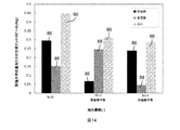
本節で研究した2つのシステムに対する類似のGOR値を理解するために、図14を参照されたい。システムにおける脱塩水kg当たりの、加湿器88および除湿器86において生成されるエントロピーが、固定された頂部ブライン温度と、原料水の温度と、加湿器および除湿器におけるエンタルピーピンチとに対して示されている。このシステムにおいて、除湿器が完全に平衡化されると、除湿器86における生成エントロピーは、物質の抽出および注入なしのシステムの場合の1/4に低下するが、加湿器88における生成エントロピーは65%増加する。除湿器86を平衡化する間、加湿器88は平衡状態から離れる。加湿器が完全に平衡したシステムにおいては、加湿器88におけるエントロピー生成は、物質の抽出または注入なしのシステムの場合の1/3未満に低下する。除湿器86における生成エントロピーは殆ど変化しない。システムにおける脱塩水kg当たりの全生成エントロピー90は、ここで検討した両システムにおいてほぼ同じであり、従って、これらのシステムはよく似たGOR値を有する。類似の傾向が他の境界条件に対しても認められる。
To understand similar GOR values for the two systems studied in this section, please refer to FIG. The entropy generated in
結論的に、本節に報告した種々の場合における平衡化によるエントロピー生成の変化に関する研究に基づいて、連続的平衡化による全システムのエントロピー生成における低減は、同じエンタルピーピンチにおいて、「除湿器平衡」システムおよび「加湿器平衡」システムに対して非常に類似していることが分かった。従って、GORもこの2つのシステムに対して類似していることが分かった。 In conclusion, based on the study on changes in entropy production due to equilibration in various cases reported in this section, the reduction in entropy production of the entire system due to continuous equilibration is the same as the “dehumidifier equilibrium” system in the same enthalpy pinch And was found to be very similar to the “humidifier balance” system. Thus, GOR was found to be similar for the two systems.
抽出/注入の個数の影響
(種々のエンタルピーピンチにおける)HDHシステムの性能に対する抽出/注入の個数の影響が図15に示されている。この図においては、無限個の抽出/注入システムが菱形で、単一の抽出/注入システムがアステリスクで、抽出なしのシステムが円形でプロットされている。この図から、いくつかの重要な観察結果を導出できる。
Effect of Extract / Injection Number The effect of the number of extract / injections on the performance of the HDH system (at various enthalpy pinches) is shown in FIG. In this figure, an infinite number of extraction / infusion systems are diamond-shaped, a single extraction / infusion system is an asterisk, and a system without extraction is plotted in a circle. From this figure, some important observations can be derived.
最初に、熱力学的平衡は、加湿器および除湿器が約27kJ/kg乾燥空気未満のエンタルピーピンチを有する場合にのみ、HDHサイクルにおいて有効であることが分かる。種々の境界条件に対して、エンタルピーピンチが上記の値を超えると、抽出または注入が全くないシステムの場合との性能(GOR)における差異は小さい(すなわち20%未満)であることが分かった。さらに、加湿器および除湿器におけるエンタルピーピンチの値が非常に低い(ψ≦7kJ/kg乾燥空気)場合には、無限個の抽出および注入による連続的平衡化が、単一の抽出および注入によって得られる結果よりも遥かに良好な結果をもたらすことが分かった。頂部のブライン温度が80℃であり、原料の水の温度が20℃であり、加湿器および除湿器のサイズが「無限大」(ψhum=ψdeh=0kJ/kg乾燥空気)である場合には、(無限個の抽出/注入を備えた類似システムの場合のGORが109.7であるのに比較して、)単一の抽出/注入の場合のGORが8.2であることが分かった。エンタルピーピンチの値がさらに高ければ(7kJ/kg乾燥空気<ψ≦15kJ/kg乾燥空気)、単一の抽出/注入によって、全システムのエントロピー生成が、およそ無限個の抽出/注入によって作出される量に類似の量だけ低減した。さらに高いエンタルピーピンチの値(15kJ/kg乾燥空気<ψ≦27kJ/kg乾燥空気)においては、単一抽出が無限個抽出の性能を超えるが、これは意外な結果として見ることができる。本発明者らは、これを、無限個および単一の抽出/注入平衡化が、加湿器88および除湿器86におけるエントロピー生成にどのように影響するかを考察することによって理解することを試みる(図16参照)。
Initially, thermodynamic equilibrium is found to be effective in the HDH cycle only when the humidifier and dehumidifier have an enthalpy pinch of less than about 27 kJ / kg dry air. For various boundary conditions, it has been found that when the enthalpy pinch exceeds the above values, the difference in performance (GOR) from a system without any extraction or injection is small (ie less than 20%). Furthermore, if the value of enthalpy pinch in the humidifier and dehumidifier is very low (ψ ≦ 7 kJ / kg dry air), continuous equilibration with infinite number of extractions and injections can be obtained with a single extraction and injection. It was found to give much better results than those obtained. When the top brine temperature is 80 ° C., the raw water temperature is 20 ° C., and the humidifier and dehumidifier sizes are “infinite” (ψ hum = ψ deh = 0 kJ / kg dry air) Shows that the GOR for a single extraction / injection is 8.2 (as compared to 109.7 for a similar system with infinite number of extraction / injections) It was. With higher enthalpy pinch values (7 kJ / kg dry air <ψ ≦ 15 kJ / kg dry air), a single extraction / injection will produce the entropy generation of the entire system with approximately infinite number of extractions / injections. Reduced by an amount similar to the amount. At higher enthalpy pinch values (15 kJ / kg dry air <ψ ≦ 27 kJ / kg dry air), single extraction exceeds the performance of infinite number extraction, which can be seen as a surprising result. We attempt to understand this by considering how infinite and single extraction / injection equilibration affects entropy generation in
図16は、ゼロ個、1つおよび無限個の抽出/注入を備えたシステムにおける加湿器88および除湿器86において、構成要素のエンタルピーピンチが20kJ/kg乾燥空気である時に生成されるエントロピーを示す。連続的な抽出/注入が適用される場合は、平衡構成要素(すなわち除湿器86)における生成エントロピーは低下するが、加湿器88における生成エントロピーは増大する。換言すれば、除湿器が平衡化された時に、加湿器は「平衡化されていない」。単一の抽出/注入の場合は、除湿器86における生成エントロピーは、無限個の抽出/注入の場合における生成エントロピーの低減分より小さい量だけ低下するが、加湿器は非平衡になっていない。このため、単一抽出/注入の場合には、全生成エントロピー90が低く、GORは高いのである。
FIG. 16 shows the entropy generated in a
さらに、連続的な抽出/注入を備えたシステムであって、加湿器または除湿器のいずれをも完全には平衡化しないが両者を部分的に平衡化するシステムを設計することが可能である。このようなシステムは、単一抽出/注入のシステムより高い性能を有する可能性がある。 In addition, it is possible to design a system with continuous extraction / infusion that does not fully equilibrate either the humidifier or dehumidifier, but partially equilibrates both. Such a system may have higher performance than a single extraction / injection system.
適用例
本明細書に記述する方法および装置は、例えば、小さな農村集落における水浄化を提供するために用いることが可能である。このような用途におけるエネルギー源(例えばバイオマス)は低質のエネルギーを提供する可能性があるが、化石燃料の利用可能性がなくかつ確実な電源網が欠落しているという理由から、バイオマスは多くの場合最良の選択である。本明細書に記述する方法は、(低質の熱によって作動する)基本的なHDHシステムのエネルギー効率を、100%までの量だけ改善することが可能である。このエネルギー効率の改善は、エネルギーコストの低減を支援し、小さな農村集落に浄化された水を提供するシステムを実現できる。
Application Examples The methods and apparatus described herein can be used, for example, to provide water purification in small rural settlements. Energy sources (such as biomass) in such applications can provide low-quality energy, but because of the lack of availability of fossil fuels and lack of a reliable power network, The case is the best choice. The method described herein can improve the energy efficiency of a basic HDH system (operating with low quality heat) by an amount of up to 100%. This improvement in energy efficiency can help reduce energy costs and provide a system that provides purified water to small rural communities.
特に米国におけるこの方法および装置のもう1つの有望な用途は、シェールガスまたはシェールオイルの抽出から生じる生成水および逆流水の処理である。本開示の方法は、この用途に対しても、HDH技術をコスト効率的なものにする際に主要な役割を果たすことができる。 Another promising application of this method and apparatus, particularly in the United States, is the treatment of product water and backflow water resulting from extraction of shale gas or shale oil. The method of the present disclosure can also play a major role in making HDH technology cost effective for this application.
本発明の実施形態の記述において、明確さのために特定の用語法を用いている。記述目的のため、特定の用語は、同様の方法で作動して同様の結果を達成するような技術的および機能的な均等物を少なくとも含むように意図されている。さらに、本発明の特定の実施形態が複数のシステム要素または方法のステップを含むいくつかの例においては、それらの要素またはステップを単一の要素またはステップと置き換えることができる。同様に、単一の要素またはステップは、同じ目的に役立つ複数の要素またはステップと置き換えることができる。また、さらに、種々の特性のパラメータまたは他の値が、本発明の実施形態用として本明細書において規定される場合、それらのパラメータまたは値は、そうでない旨規定されない限り、1/100、1/50、1/20、1/10、1/5、1/3、1/2、2/3、3/4、4/5、9/10、19/20、49/50、99/100などだけ上方または下方に(、または、1、2、3、4、5、6、8、10、20、50、100などの係数だけ上方に)調整することが可能であり、あるいは、その丸められた近似値によって調整することが可能である。また、さらに、本発明は、その特定の実施形態を参照して示されかつ記述されているが、当業者は、形態および詳細における種々の置換および変更を、本発明の範囲から離れることなく、その実施形態においてなし得ることを理解するであろう。また、さらに、他の態様、機能および利点も本発明の範囲内であり、かつ、本発明のすべての実施形態は、必ずしも前記の利点のすべてを実現する必要はなく、前記の特性のすべてを有する必要もない。また、さらに、本明細書において、一実施形態と関連付けて言及したステップ、要素および形体は、他の実施形態との関連においても同様に使用可能である。参照文献のテキスト、雑誌の論文、特許、特許出願などを含む、本明細書の全文を通して引用された参照文献の内容は、参照によって、その全体が本願に組み込まれ、本発明の実施形態は、これらの参照文献からの適切な構成要素、ステップおよび特徴を含むことができ、または含まなくてもよい。また、さらに、背景技術の節において特定した構成要素およびステップは、本開示に統合されており、本発明の範囲内の開示の他の個所で記述した構成要素またはステップと関連付けて、あるいはそれらの代わりに用いることが可能である。方法に関する請求項であって、−参照の簡易さのために付加された順序付き前書き文字を伴った、またはそれなしの−段階的な工程が特定の順序で列挙される方法請求項においては、その段階的な工程は、用語または語句によってそうでない旨規定されるかまたは含意されない限り、時間的に、それらが列挙される順序に限定されると解釈されるべきではない。 In describing embodiments of the present invention, specific terminology is used for the sake of clarity. For descriptive purposes, certain terms are intended to include at least technical and functional equivalents that operate in a similar manner to achieve a similar result. Further, in some examples where particular embodiments of the invention include multiple system elements or method steps, those elements or steps may be replaced with a single element or step. Similarly, a single element or step can be replaced with multiple elements or steps serving the same purpose. Still further, if parameters or other values of various characteristics are defined herein for embodiments of the present invention, those parameters or values are 1/100, 1 unless otherwise specified. / 50, 1/20, 1/10, 1/5, 1/3, 1/2, 2/3, 3/4, 4/5, 9/10, 19/20, 49/50, 99/100 Can be adjusted up or down (or up by a factor of 1, 2, 3, 4, 5, 6, 8, 10, 20, 50, 100, etc.) or rounded It is possible to adjust according to the approximate value obtained. Furthermore, while the present invention has been shown and described with reference to specific embodiments thereof, those skilled in the art will recognize that various substitutions and changes in form and detail may be made without departing from the scope of the invention. It will be understood that this can be done in that embodiment. Still further, other aspects, features and advantages are within the scope of the invention, and all embodiments of the invention need not necessarily realize all of the advantages described above. There is no need to have it. Still further, the steps, elements, and features referred to herein in connection with one embodiment can be used in the context of other embodiments as well. The contents of references cited throughout the specification, including text of references, journal articles, patents, patent applications, etc., are incorporated herein by reference in their entirety, and embodiments of the present invention include: Appropriate components, steps and features from these references may or may not be included. Still further, the components and steps identified in the background section are incorporated into this disclosure and are associated with, or associated with, the components or steps described elsewhere in the disclosure within the scope of the present invention. It can be used instead. In a method claim, wherein the step-steps are listed in a specific order, with or without an ordered preface added for ease of reference. The staged steps should not be construed as limited in time to the order in which they are listed, unless otherwise stated or implied by a term or phrase.
Claims (16)
キャリアガスの混合体の流れを、大気圧未満の圧力で運転できる複合型熱および物質移動装置における流体流れの径路を通して導くステップと、
前記キャリアガス混合体中の蒸発可能な成分の含有量を、液体組成物からの蒸発可能な成分の蒸発によって、あるいは、前記キャリアガス混合体からの蒸発可能な成分の凝縮によって実質的に変化させるために、熱および物質を、前記キャリアガス混合体から、または前記キャリアガス混合体に、前記蒸発可能な成分を液体状態において含み、前記キャリアガス混合体とは反対方向に流れる前記液体組成物との直接的または間接的な相互作用によって移動させるステップであって、それによって、前記熱および物質の移動プロセスが行われる前の前記キャリアガス混合体中の蒸発可能な成分の濃度とは異なる蒸発可能な成分の濃度を有するキャリアガス混合体の流れを生成するステップと、
(a)前記キャリアガス混合体および(b)前記液体組成物の少なくともいずれかの質量流量を変化させるステップであって、前記(a)の場合は、前記複合型熱および物質移動装置における流体流れの径路内の少なくとも1つの中間位置から前記キャリアガス混合体を抽出または注入することによって行われ、前記(b)の場合は、前記熱および物質移動装置における流体流れの径路内の少なくとも1つの中間位置から前記液体組成物を抽出または注入することによって行われ、抽出および注入による前記質量流量の変化が、前記装置における平均局所エンタルピーピンチを低減させる、ステップと、
を含んでおり、
前記熱および物質移動装置における前記流体流れの経路に沿った同一位置における前記キャリア混合体中の蒸発可能な成分の質量のキャリアガスの質量に対する比を局所的な湿度比と定め、(i)前記キャリアガス混合体のバルク流れの局所的な湿度比と、(ii)前記キャリアガス混合体と前記液体組成物の界面における前記キャリアガス混合体の局所的な湿度比との差となる局所的な湿度比差の前記流体流れの経路に沿った変化率を、前記流体流れの経路に沿った同一位置における前記キャリアガス混合体の流れの温度と前記液体組成物の流れの温度の差となる温度差の前記流体流れの経路に沿った変化率よりも小さくするように、前記熱および物質移動装置を運転することを特徴とする方法。 In a method for reducing entropy production in a combined heat and mass transfer device,
Directing the flow of the carrier gas mixture through a fluid flow path in a combined heat and mass transfer device capable of operating at a pressure below atmospheric pressure;
The content of the evaporable component in the carrier gas mixture is substantially changed by evaporation of the evaporable component from the liquid composition or by condensation of the evaporable component from the carrier gas mixture. For that purpose, the liquid composition comprising heat and substance from the carrier gas mixture or in the carrier gas mixture in a liquid state with the evaporable component flowing in a direction opposite to the carrier gas mixture; By direct or indirect interaction of the gas, thereby evaporating different from the concentration of evaporable components in the carrier gas mixture prior to the heat and mass transfer process Generating a flow of a carrier gas mixture having a concentration of various components;
(A) changing the mass flow rate of at least one of the carrier gas mixture and (b) the liquid composition, in the case of (a), fluid flow in the combined heat and mass transfer device By extracting or injecting the carrier gas mixture from at least one intermediate position in the path of, and in the case of (b), at least one intermediate in the path of fluid flow in the heat and mass transfer device Extracting or injecting the liquid composition from a location, wherein the change in mass flow rate due to extraction and injection reduces the mean local enthalpy pinch in the device;
A and Nde including,
Defining the ratio of the mass of evaporable components in the carrier mixture at the same location along the fluid flow path in the heat and mass transfer device to the mass of the carrier gas as the local humidity ratio; (i) The local humidity ratio of the bulk flow of the carrier gas mixture and (ii) the local humidity ratio of the carrier gas mixture at the interface of the carrier gas mixture and the liquid composition The rate of change of the humidity ratio difference along the fluid flow path is a temperature that is the difference between the temperature of the carrier gas mixture flow and the temperature of the liquid composition flow at the same position along the fluid flow path. A method of operating the heat and mass transfer device to make the difference less than the rate of change along the fluid flow path .
蒸発可能な成分およびキャリアガスを含むキャリアガス混合体の流れを、充填床の加湿器内の流体流れの径路を通して導くステップであって、前記システムは大気圧未満の圧力で運転できる、ステップと、
前記キャリアガス混合体中の蒸発可能な成分の含有量を、液体組成物からの蒸発可能な成分の蒸発によって実質的に増大させるために、熱および物質を、前記キャリアガス混合体に、前記蒸発可能な成分をその一成分として液体状態において含み、前記キャリアガス混合体とは反対方向に流れる前記液体組成物との直接的な相互作用によって移動させるステップと、
前記キャリアガス混合体を前記加湿器から除湿器に導くステップであって、熱および物質が、前記キャリアガス混合体から、前記除湿器内の流体流れの径路における前記液体組成物との間接的な相互作用によって移動し、それによって、前記キャリアガス混合体中の前記蒸発可能な成分の含有量が低減され、かつ、前記液体組成物が予熱される、ステップと、
(a)前記キャリアガス混合体および(b)前記液体組成物の少なくともいずれかの質量流量を変化させるステップであって、前記(a)の場合は、前記加湿器における流体流れの径路内の少なくとも1つの中間位置から前記キャリアガス混合体を抽出し、抽出された前記キャリアガス混合体を前記除湿器内の対応する位置に注入することによって行われ、前記(b)の場合は、前記加湿器における流体流れの径路内の少なくとも1つの中間位置から前記液体組成物を抽出し、前記液体組成物を前記除湿器内の対応する位置に注入することによって行われ、前記対応する位置はそれらの位置におけるそれぞれの流体流れの温度と蒸気濃度が略同一である位置であり、抽出および注入による前記質量流量の変化が前記除湿器内の平均局所エンタルピーピンチを低減する、ステップと、
を含む、ことを特徴とする方法。 In a method for reducing entropy production in a humidification-dehumidification system,
Directing a flow of a carrier gas mixture comprising a vaporizable component and a carrier gas through a fluid flow path in a humidifier of a packed bed, wherein the system can be operated at a pressure below atmospheric pressure;
In order to substantially increase the content of the evaporable component in the carrier gas mixture by evaporation of the evaporable component from the liquid composition, heat and material are transferred to the carrier gas mixture to the evaporation. Including a possible component in the liquid state as one component and being moved by direct interaction with the liquid composition flowing in a direction opposite to the carrier gas mixture;
Directing the carrier gas mixture from the humidifier to a dehumidifier, wherein heat and material are indirectly from the carrier gas mixture to the liquid composition in a fluid flow path within the dehumidifier. Moving by interaction, thereby reducing the content of the evaporable component in the carrier gas mixture and preheating the liquid composition;
(A) a step of changing a mass flow rate of at least one of the carrier gas mixture and (b) the liquid composition, and in the case of (a), at least within a fluid flow path in the humidifier. The carrier gas mixture is extracted from one intermediate position, and the extracted carrier gas mixture is injected into a corresponding position in the dehumidifier. In the case of (b), the humidifier The liquid composition is extracted from at least one intermediate position in the fluid flow path and injected into the corresponding position in the dehumidifier, the corresponding position being those positions. The temperature and vapor concentration of each fluid flow at the same position are substantially the same, and the change in the mass flow rate due to extraction and injection is the average local enter in the dehumidifier To reduce the Pipinchi, and the step,
A method characterized by comprising:
Applications Claiming Priority (3)
| Application Number | Priority Date | Filing Date | Title |
|---|---|---|---|
| US13/550,094 US8496234B1 (en) | 2012-07-16 | 2012-07-16 | Thermodynamic balancing of combined heat and mass exchange devices |
| US13/550,094 | 2012-07-16 | ||
| PCT/US2013/049129 WO2014014660A1 (en) | 2012-07-16 | 2013-07-02 | Thermodynamic balancing of combined heat and mass exchange devices |
Publications (3)
| Publication Number | Publication Date |
|---|---|
| JP2015527930A JP2015527930A (en) | 2015-09-24 |
| JP2015527930A5 JP2015527930A5 (en) | 2016-09-01 |
| JP6005860B2 true JP6005860B2 (en) | 2016-10-12 |
Family
ID=48794229
Family Applications (1)
| Application Number | Title | Priority Date | Filing Date |
|---|---|---|---|
| JP2015523110A Active JP6005860B2 (en) | 2012-07-16 | 2013-07-02 | Thermodynamic equilibrium of combined heat and mass exchange equipment. |
Country Status (14)
| Country | Link |
|---|---|
| US (2) | US8496234B1 (en) |
| EP (1) | EP2872229A1 (en) |
| JP (1) | JP6005860B2 (en) |
| CN (2) | CN104540564B (en) |
| AU (1) | AU2013290626B2 (en) |
| BR (1) | BR112015000829A2 (en) |
| CA (1) | CA2875826C (en) |
| CL (1) | CL2015000026A1 (en) |
| CO (1) | CO7240438A2 (en) |
| IN (1) | IN2014DN09916A (en) |
| MX (1) | MX2015000632A (en) |
| SG (1) | SG11201407825RA (en) |
| WO (1) | WO2014014660A1 (en) |
| ZA (1) | ZA201500996B (en) |
Families Citing this family (43)
| Publication number | Priority date | Publication date | Assignee | Title |
|---|---|---|---|---|
| US9842498B2 (en) * | 2011-07-05 | 2017-12-12 | Qualcomm Incorporated | Road-traffic-based group, identifier, and resource selection in vehicular peer-to-peer networks |
| US9072984B2 (en) * | 2011-09-23 | 2015-07-07 | Massachusetts Institute Of Technology | Bubble-column vapor mixture condenser |
| US8496234B1 (en) * | 2012-07-16 | 2013-07-30 | Massachusetts Institute Of Technology | Thermodynamic balancing of combined heat and mass exchange devices |
| US9120033B2 (en) | 2013-06-12 | 2015-09-01 | Massachusetts Institute Of Technology | Multi-stage bubble column humidifier |
| CN108195016B (en) * | 2013-09-12 | 2022-08-05 | 格雷迪安特公司 | Humidifier device, condenser device and bubble column condenser |
| WO2015077887A1 (en) * | 2013-11-26 | 2015-06-04 | Saltworks Technologies Inc. | Multiple effect concentration swap de-scaling system |
| DE102013224351B4 (en) * | 2013-11-28 | 2017-03-30 | Reinhold Barth | Device for generating service water |
| CA2934026C (en) | 2013-12-18 | 2020-03-24 | Gradiant Corporation | Counter-flow heat/mass exchange feedback control |
| CN106457058B (en) * | 2014-01-31 | 2019-06-21 | Lat水务有限公司 | The evaporation of adverse current liquefied gas and condensing plant with crushing shell |
| SG11201708187SA (en) * | 2015-03-10 | 2017-11-29 | Oneworld Corp | Fresh-water generating apparatus |
| US20160332891A1 (en) * | 2015-05-15 | 2016-11-17 | New Mexico Technical Research Foundation | Method and system for purifying produced water |
| US9266748B1 (en) | 2015-05-21 | 2016-02-23 | Gradiant Corporation | Transiently-operated desalination systems with heat recovery and associated methods |
| US10981082B2 (en) | 2015-05-21 | 2021-04-20 | Gradiant Corporation | Humidification-dehumidification desalination systems and methods |
| MX2017014906A (en) * | 2015-05-21 | 2018-06-22 | Gradiant Corp | Humidification-dehumidification desalination systems and methods. |
| US10143936B2 (en) | 2015-05-21 | 2018-12-04 | Gradiant Corporation | Systems including an apparatus comprising both a humidification region and a dehumidification region with heat recovery and/or intermediate injection |
| US10143935B2 (en) | 2015-05-21 | 2018-12-04 | Gradiant Corporation | Systems including an apparatus comprising both a humidification region and a dehumidification region |
| US10463985B2 (en) | 2015-05-21 | 2019-11-05 | Gradiant Corporation | Mobile humidification-dehumidification desalination systems and methods |
| AU2016298326B2 (en) | 2015-07-29 | 2022-08-04 | Gradiant Corporation | Osmotic desalination methods and associated systems |
| US10245555B2 (en) | 2015-08-14 | 2019-04-02 | Gradiant Corporation | Production of multivalent ion-rich process streams using multi-stage osmotic separation |
| WO2017030932A1 (en) | 2015-08-14 | 2017-02-23 | Gradiant Corporation | Selective retention of multivalent ions |
| US10627129B2 (en) * | 2015-09-01 | 2020-04-21 | Belimo Holding Ag | Method and system for operating a thermal energy exchanger |
| US10345058B1 (en) | 2015-11-18 | 2019-07-09 | Gradiant Corporation | Scale removal in humidification-dehumidification systems |
| CN105413213B (en) * | 2015-12-22 | 2017-07-11 | 袁一军 | A kind of solution component separation method and system |
| US10294123B2 (en) | 2016-05-20 | 2019-05-21 | Gradiant Corporation | Humidification-dehumidification systems and methods at low top brine temperatures |
| US10513445B2 (en) | 2016-05-20 | 2019-12-24 | Gradiant Corporation | Control system and method for multiple parallel desalination systems |
| TWI716412B (en) * | 2016-06-16 | 2021-01-21 | 日商世界一家股份有限公司 | Fresh water generator |
| CN106006807A (en) * | 2016-08-09 | 2016-10-12 | 陕西和尊能源科技有限公司 | Low-temperature distillation system |
| CN106765704B (en) * | 2016-12-26 | 2019-07-09 | 南京航空航天大学 | Double caloic coupled solar hot-air type vapo(u)rization systems and its method |
| CN106621420B (en) * | 2016-12-29 | 2018-11-20 | 上海理工大学 | A kind of liquid concentration water removal device |
| USD841119S1 (en) * | 2017-01-13 | 2019-02-19 | Across International Llc | Distillation head |
| CN106693411A (en) * | 2017-01-25 | 2017-05-24 | 天津中医药大学 | High-efficiency normal-pressure low-temperature concentration system applicable to traditional Chinese medicinal liquor |
| US20210122545A1 (en) * | 2017-07-12 | 2021-04-29 | Hewlett-Packard Development Company, L.P. | Treatment composition for packaging liner |
| CN108043054A (en) * | 2017-12-29 | 2018-05-18 | 浙江镭弘激光科技有限公司 | A kind of energy-saving, environment-friendly and high-efficiency evaporating kettle |
| CN108408810B (en) * | 2018-03-21 | 2023-09-01 | 国家能源投资集团有限责任公司 | System and method for crystallizing and drying waste water concentrate fluidized by hot air pressure swing circulation |
| AU2019325567A1 (en) | 2018-08-22 | 2021-03-04 | Gradiant Corporation | Liquid solution concentration system comprising isolated subsystem and related methods |
| CN109350989A (en) * | 2018-11-08 | 2019-02-19 | 广东莞绿环保工程有限公司 | A kind of half cycle energy conservation evaporated crystallization device |
| US11685680B2 (en) * | 2019-11-18 | 2023-06-27 | Your Rain Systems, Inc. | System and method of rain water collection and purification |
| US11365894B2 (en) * | 2020-02-10 | 2022-06-21 | King Fahd University Of Petroleum And Minerals | Closed-air closed-desiccant humidifier-dehumidifier atmospheric water generator system |
| WO2021176190A1 (en) * | 2020-03-06 | 2021-09-10 | Euro Energy Solutions Limited | Methods and apparatus for desalination |
| US11618693B2 (en) * | 2020-11-02 | 2023-04-04 | King Fahd University Of Petroleum And Minerals | Multimode system for cooling and desalination |
| US11618692B2 (en) * | 2020-11-02 | 2023-04-04 | King Fahd University Of Petroleum And Minerals | Cooling and desalination system |
| AU2021383601A1 (en) | 2020-11-17 | 2023-06-08 | Gradiant Corporaton | Osmotic methods and systems involving energy recovery |
| USD919040S1 (en) * | 2021-01-07 | 2021-05-11 | Elliot Kremerman | Distillation tube with fraction collector |
Family Cites Families (14)
| Publication number | Priority date | Publication date | Assignee | Title |
|---|---|---|---|---|
| US2858903A (en) * | 1955-01-11 | 1958-11-04 | Madeleine Fallon | Methods for the treatment of industrial aerosols |
| US2857015A (en) * | 1955-10-20 | 1958-10-21 | Surface Combustion Corp | Dehumidifying apparatus |
| US3558436A (en) * | 1968-07-30 | 1971-01-26 | Auscoteng Pty Ltd | Distilation apparatus for desalinisation of saline water to recover fresh water as condensate |
| US3831667A (en) * | 1971-02-04 | 1974-08-27 | Westinghouse Electric Corp | Combination wet and dry cooling system for a steam turbine |
| US4072182A (en) * | 1977-01-05 | 1978-02-07 | International Power Technology, Inc. | Pressure staged heat exchanger |
| US5124004A (en) * | 1983-08-22 | 1992-06-23 | Trustees Of Dartmouth College | Distillation process for ethanol |
| WO2002087722A1 (en) * | 2001-05-02 | 2002-11-07 | Peter Vinz | Evaporation method for the production of clean drinking water and high-percentage brine from untreated water containing salt |
| ES2185514B1 (en) * | 2001-10-13 | 2004-01-01 | Hernandez Fernando M Hernandez | PLANT FOR THE OBTAINING OF WATER EXEMPT FROM SALT FROM SEAWATER, AT LOW TEMPERATURE, WITH CONTINUOUS OPERATION AND RECOVERY OF ENTALPIA. |
| DE10215079B4 (en) | 2002-04-05 | 2005-11-24 | Thomas Brendel | Process for distilling or desalting liquids |
| US7431805B2 (en) * | 2003-12-03 | 2008-10-07 | Arizona Board Of Regents | Method and apparatus for simultaneous heat and mass transfer utilizing a carrier-gas at various absolute pressures |
| DE102005046643A1 (en) | 2005-09-29 | 2007-04-19 | Rexxon Gmbh | Device for separating a liquid from the foreign substances dissolved in it |
| US8292272B2 (en) * | 2009-09-04 | 2012-10-23 | Massachusetts Institute Of Technology | Water separation under reduced pressure |
| US8252092B2 (en) | 2009-10-05 | 2012-08-28 | Massachusetts Institute Of Technology | Water separation under varied pressure |
| US8496234B1 (en) * | 2012-07-16 | 2013-07-30 | Massachusetts Institute Of Technology | Thermodynamic balancing of combined heat and mass exchange devices |
-
2012
- 2012-07-16 US US13/550,094 patent/US8496234B1/en active Active
-
2013
- 2013-06-24 US US13/924,732 patent/US9416800B2/en active Active
- 2013-07-02 CN CN201380034058.1A patent/CN104540564B/en active Active
- 2013-07-02 WO PCT/US2013/049129 patent/WO2014014660A1/en active Application Filing
- 2013-07-02 EP EP13737764.4A patent/EP2872229A1/en active Pending
- 2013-07-02 MX MX2015000632A patent/MX2015000632A/en active IP Right Grant
- 2013-07-02 IN IN9916DEN2014 patent/IN2014DN09916A/en unknown
- 2013-07-02 BR BR112015000829A patent/BR112015000829A2/en active Search and Examination
- 2013-07-02 JP JP2015523110A patent/JP6005860B2/en active Active
- 2013-07-02 SG SG11201407825RA patent/SG11201407825RA/en unknown
- 2013-07-02 AU AU2013290626A patent/AU2013290626B2/en active Active
- 2013-07-02 CA CA2875826A patent/CA2875826C/en active Active
- 2013-07-02 CN CN201610803815.2A patent/CN106492488B/en active Active
-
2014
- 2014-12-30 CO CO14286200A patent/CO7240438A2/en unknown
-
2015
- 2015-01-07 CL CL2015000026A patent/CL2015000026A1/en unknown
- 2015-02-12 ZA ZA2015/00996A patent/ZA201500996B/en unknown
Also Published As
| Publication number | Publication date |
|---|---|
| IN2014DN09916A (en) | 2015-08-14 |
| US20140014212A1 (en) | 2014-01-16 |
| CO7240438A2 (en) | 2015-04-17 |
| CA2875826A1 (en) | 2014-01-23 |
| WO2014014660A1 (en) | 2014-01-23 |
| CA2875826C (en) | 2015-10-13 |
| JP2015527930A (en) | 2015-09-24 |
| CN106492488A (en) | 2017-03-15 |
| BR112015000829A2 (en) | 2017-06-27 |
| CN106492488B (en) | 2019-04-23 |
| AU2013290626B2 (en) | 2015-02-05 |
| US9416800B2 (en) | 2016-08-16 |
| SG11201407825RA (en) | 2015-01-29 |
| CN104540564B (en) | 2016-10-05 |
| ZA201500996B (en) | 2016-06-29 |
| EP2872229A1 (en) | 2015-05-20 |
| US8496234B1 (en) | 2013-07-30 |
| AU2013290626A1 (en) | 2014-12-11 |
| MX2015000632A (en) | 2015-10-22 |
| CL2015000026A1 (en) | 2015-09-04 |
| CN104540564A (en) | 2015-04-22 |
Similar Documents
| Publication | Publication Date | Title |
|---|---|---|
| JP6005860B2 (en) | Thermodynamic equilibrium of combined heat and mass exchange equipment. | |
| JP6224235B2 (en) | Multistage bubble humidifier | |
| US8465006B2 (en) | Separation of a vaporizable component under reduced pressure | |
| US8252092B2 (en) | Water separation under varied pressure | |
| Saidur et al. | An overview of different distillation methods for small scale applications | |
| US8647477B2 (en) | High-efficiency thermal-energy-driven water purification system | |
| Choi | On the brine re-utilization of a multi-stage flashing (MSF) desalination plant | |
| JP5801663B2 (en) | Seawater desalination equipment | |
| US20170008776A1 (en) | Facility and method for treating water pumped in a natural environment by evaporation/condensation | |
| Lawal et al. | Hybrid multi-stage flash (MSF) and membrane distillation (MD) desalination system for energy saving and brine minimization | |
| Narayan et al. | Status of humidification dehumidification desalination technology | |
| KR101683602B1 (en) | Marine power plant using evaporative desalination system | |
| US10472258B2 (en) | Thermal energy-driven mechanical compression humidification-dehumidification water purification | |
| Memon et al. | Parametric investigation of modular configuration of multi-stage direct contact membrane distillation powered by waste heat of wind turbine | |
| CN111656123B (en) | Mechanical vapor compression device with low compression ratio | |
| Xu et al. | Analysis of a multi-stage air gap diffusion distillation system powered by low-grade sensible heat | |
| Kwan et al. | Comparative meta-analysis of desalination and atmospheric water harvesting technologies based on the minimum energy of separation | |
| Otanicar et al. | Thermodynamic analysis of hybrid humidification-dehumidification (HDH)-Reverse osmosis (RO) desalination system powered by concentrating photovoltaic/thermal solar collector | |
| KR20130123888A (en) | Salt manufacturing, seawater desalination and electricity generation system using solar energy | |
| Velmurugan et al. | Humidificaton-Dehumidification Desalination System-An Overview | |
| KR102063245B1 (en) | Variable MVR Evaporation Device and Process with Fluctuating Load | |
| Jaber | Modified Multi Effect Desalination Systems with Mechanical Vapor Compression | |
| Dave et al. | Experimental Investigation of Zero-and Single-Extraction Humidification-Dehumidification Desalination System |
Legal Events
| Date | Code | Title | Description |
|---|---|---|---|
| A975 | Report on accelerated examination |
Free format text: JAPANESE INTERMEDIATE CODE: A971005 Effective date: 20150727 |
|
| A131 | Notification of reasons for refusal |
Free format text: JAPANESE INTERMEDIATE CODE: A131 Effective date: 20150804 |
|
| A601 | Written request for extension of time |
Free format text: JAPANESE INTERMEDIATE CODE: A601 Effective date: 20151104 |
|
| A524 | Written submission of copy of amendment under article 19 pct |
Free format text: JAPANESE INTERMEDIATE CODE: A524 Effective date: 20151203 |
|
| A521 | Request for written amendment filed |
Free format text: JAPANESE INTERMEDIATE CODE: A523 Effective date: 20151204 |
|
| A131 | Notification of reasons for refusal |
Free format text: JAPANESE INTERMEDIATE CODE: A131 Effective date: 20160209 |
|
| A601 | Written request for extension of time |
Free format text: JAPANESE INTERMEDIATE CODE: A601 Effective date: 20160506 |
|
| A524 | Written submission of copy of amendment under article 19 pct |
Free format text: JAPANESE INTERMEDIATE CODE: A524 Effective date: 20160706 |
|
| A521 | Request for written amendment filed |
Free format text: JAPANESE INTERMEDIATE CODE: A523 Effective date: 20160707 |
|
| TRDD | Decision of grant or rejection written | ||
| A01 | Written decision to grant a patent or to grant a registration (utility model) |
Free format text: JAPANESE INTERMEDIATE CODE: A01 Effective date: 20160809 |
|
| A61 | First payment of annual fees (during grant procedure) |
Free format text: JAPANESE INTERMEDIATE CODE: A61 Effective date: 20160907 |
|
| R150 | Certificate of patent or registration of utility model |
Ref document number: 6005860 Country of ref document: JP Free format text: JAPANESE INTERMEDIATE CODE: R150 |
|
| R250 | Receipt of annual fees |
Free format text: JAPANESE INTERMEDIATE CODE: R250 |
|
| R250 | Receipt of annual fees |
Free format text: JAPANESE INTERMEDIATE CODE: R250 |
|
| R250 | Receipt of annual fees |
Free format text: JAPANESE INTERMEDIATE CODE: R250 |
|
| R250 | Receipt of annual fees |
Free format text: JAPANESE INTERMEDIATE CODE: R250 |
|
| R250 | Receipt of annual fees |
Free format text: JAPANESE INTERMEDIATE CODE: R250 |