JP5997289B2 - Method for producing flexographic printing forms by welding the ends of photosensitive elements using microwave energy - Google Patents
Method for producing flexographic printing forms by welding the ends of photosensitive elements using microwave energy Download PDFInfo
- Publication number
- JP5997289B2 JP5997289B2 JP2014544793A JP2014544793A JP5997289B2 JP 5997289 B2 JP5997289 B2 JP 5997289B2 JP 2014544793 A JP2014544793 A JP 2014544793A JP 2014544793 A JP2014544793 A JP 2014544793A JP 5997289 B2 JP5997289 B2 JP 5997289B2
- Authority
- JP
- Japan
- Prior art keywords
- photosensitive
- layer
- photosensitive element
- radiation
- microwave
- Prior art date
- Legal status (The legal status is an assumption and is not a legal conclusion. Google has not performed a legal analysis and makes no representation as to the accuracy of the status listed.)
- Expired - Fee Related
Links
Images


Classifications
-
- B—PERFORMING OPERATIONS; TRANSPORTING
- B32—LAYERED PRODUCTS
- B32B—LAYERED PRODUCTS, i.e. PRODUCTS BUILT-UP OF STRATA OF FLAT OR NON-FLAT, e.g. CELLULAR OR HONEYCOMB, FORM
- B32B37/00—Methods or apparatus for laminating, e.g. by curing or by ultrasonic bonding
- B32B37/06—Methods or apparatus for laminating, e.g. by curing or by ultrasonic bonding characterised by the heating method
-
- G—PHYSICS
- G03—PHOTOGRAPHY; CINEMATOGRAPHY; ANALOGOUS TECHNIQUES USING WAVES OTHER THAN OPTICAL WAVES; ELECTROGRAPHY; HOLOGRAPHY
- G03F—PHOTOMECHANICAL PRODUCTION OF TEXTURED OR PATTERNED SURFACES, e.g. FOR PRINTING, FOR PROCESSING OF SEMICONDUCTOR DEVICES; MATERIALS THEREFOR; ORIGINALS THEREFOR; APPARATUS SPECIALLY ADAPTED THEREFOR
- G03F7/00—Photomechanical, e.g. photolithographic, production of textured or patterned surfaces, e.g. printing surfaces; Materials therefor, e.g. comprising photoresists; Apparatus specially adapted therefor
- G03F7/16—Coating processes; Apparatus therefor
- G03F7/18—Coating curved surfaces
-
- B—PERFORMING OPERATIONS; TRANSPORTING
- B41—PRINTING; LINING MACHINES; TYPEWRITERS; STAMPS
- B41N—PRINTING PLATES OR FOILS; MATERIALS FOR SURFACES USED IN PRINTING MACHINES FOR PRINTING, INKING, DAMPING, OR THE LIKE; PREPARING SUCH SURFACES FOR USE AND CONSERVING THEM
- B41N1/00—Printing plates or foils; Materials therefor
- B41N1/16—Curved printing plates, especially cylinders
-
- B—PERFORMING OPERATIONS; TRANSPORTING
- B41—PRINTING; LINING MACHINES; TYPEWRITERS; STAMPS
- B41N—PRINTING PLATES OR FOILS; MATERIALS FOR SURFACES USED IN PRINTING MACHINES FOR PRINTING, INKING, DAMPING, OR THE LIKE; PREPARING SUCH SURFACES FOR USE AND CONSERVING THEM
- B41N3/00—Preparing for use and conserving printing surfaces
-
- B—PERFORMING OPERATIONS; TRANSPORTING
- B41—PRINTING; LINING MACHINES; TYPEWRITERS; STAMPS
- B41N—PRINTING PLATES OR FOILS; MATERIALS FOR SURFACES USED IN PRINTING MACHINES FOR PRINTING, INKING, DAMPING, OR THE LIKE; PREPARING SUCH SURFACES FOR USE AND CONSERVING THEM
- B41N1/00—Printing plates or foils; Materials therefor
- B41N1/16—Curved printing plates, especially cylinders
- B41N1/22—Curved printing plates, especially cylinders made of other substances
Description
本発明は、端部で互いに溶接された2つ以上の感光性エレメントからフレキソ印刷フォーム、特に凸版印刷フォームを製造する方法であって、溶接がマイクロ波エネルギーによって行われる方法に関する。本発明は、円筒形感光性エレメントの端部をシールすることにも関する。マイクロ波エネルギーを使用することで、溶接によって、溶接線がほぼ消失した平滑な表面が得られる。 The present invention relates to a method for producing a flexographic printing form, in particular a relief printing form, from two or more photosensitive elements welded together at the ends, wherein the welding is carried out by microwave energy. The invention also relates to sealing the end of a cylindrical photosensitive element. By using microwave energy, a smooth surface with almost no weld line is obtained by welding.
フレキソ印刷版は、包装材料、たとえば、厚紙、プラスチックフィルム、アルミニウム箔などの軟質で変形が容易なものから比較的硬質なものまでの範囲の表面の印刷における使用がよく知られている。フレキソ印刷版は、米国特許第4,323,637号明細書および米国特許第4,427,759号明細書に記載されるものなどの光重合性組成物を含有する感光性エレメントから製造することができる。光重合性組成物は、一般に、エラストマー性バインダー、少なくとも1種類のモノマー、および光開始剤を含む。感光性エレメントは、一般に、支持体層と、カバーシートまたは多層カバー要素との間に挟まれた光重合性層を有する。化学線を像様露光することによって、光重合性層の光重合が露光領域で起こり、それによって層の露光領域が硬化し不溶性になる。 Flexographic printing plates are well known for use in printing on surfaces ranging from packaging materials such as cardboard, plastic film, aluminum foil, etc., which are soft and easily deformable to relatively hard. Flexographic printing plates are made from photosensitive elements containing photopolymerizable compositions such as those described in US Pat. No. 4,323,637 and US Pat. No. 4,427,759. Can do. The photopolymerizable composition generally comprises an elastomeric binder, at least one monomer, and a photoinitiator. Photosensitive elements generally have a photopolymerizable layer sandwiched between a support layer and a cover sheet or multilayer cover element. By imagewise exposure to actinic radiation, photopolymerization of the photopolymerizable layer occurs in the exposed areas, thereby hardening and exposing the exposed areas of the layer.
従来、エレメントは、好適な溶液を用いて処理され、たとえば、溶剤または水を主成分とする洗浄が行われることで、光重合性組成物層の未露光領域が除去され、フレキソ印刷に使用できる印刷レリーフが残る。溶液現像の代替法の1つとして、「乾式」熱現像方法を使用することができ、これによって未露光領域が除去される。熱現像方法においては、化学線に像様露光した光重合性層と、吸収材料との接触を、感光層の未露光部分中の組成物が軟化または溶融して吸収材料中に流動するのに十分な温度で行う。米国特許第3,060,023号明細書(Burgら)、米国特許第3,264,103号明細書(Cohenら)、米国特許第5,015,556号明細書(Martens)、米国特許第5,175,072号明細書(Martens)、米国特許第5,215,859号明細書(Martens)、および米国特許第5,279,697号明細書(Petersonら)を参照されたい。 Conventionally, the element is treated with a suitable solution, for example, cleaning with a solvent or water as a main component is performed to remove an unexposed area of the photopolymerizable composition layer and can be used for flexographic printing. Print relief remains. As an alternative to solution development, a “dry” thermal development method can be used, which removes unexposed areas. In the thermal development method, contact between the photopolymerizable layer imagewise exposed to actinic radiation and the absorbing material causes the composition in the unexposed portion of the photosensitive layer to soften or melt and flow into the absorbing material. Perform at a sufficient temperature. US Pat. No. 3,060,023 (Burg et al.), US Pat. No. 3,264,103 (Cohen et al.), US Pat. No. 5,015,556 (Martens), US Pat. See US Pat. No. 5,175,072 (Martens), US Pat. No. 5,215,859 (Martens), and US Pat. No. 5,279,697 (Peterson et al.).
光重合性材料は、溶剤キャスティング、ホットプレス、カレンダー加工、および押出成形などのいくつかの周知の方法によってシートまたは層を形成することができる。フレキソ印刷エレメントとして使用するための光重合性材料の好ましい形成方法の1つは、光重合性材料の押出成形−カレンダー加工による方法である。フィルムは、複数の層または複合フィルムを含むことができる。多層ウェブとしての印刷エレメントは、好適な寸法のシートに切断することができる。ポリマー組成物の押出成形およびカレンダー加工は、たとえばGruetzmacherらの米国特許第4,427,759号明細書に開示されている。 The photopolymerizable material can be formed into a sheet or layer by several well known methods such as solvent casting, hot pressing, calendering, and extrusion. One preferred method of forming a photopolymerizable material for use as a flexographic printing element is by extrusion-calendering of the photopolymerizable material. The film can include multiple layers or composite films. The printing element as a multilayer web can be cut into sheets of suitable dimensions. Extrusion and calendering of the polymer composition is disclosed, for example, in U.S. Pat. No. 4,427,759 to Grutzmacher et al.
しかし、多くの用途においては、より大きなエレメントを形成するため、または特定の形状のエレメントを形成するために、感光性エレメントの2つのシートの融合または溶接が必要となる。このような2つ以上の感光性エレメントの溶接によって、化学線に像様露光した感光性エレメントから未照射または未加工の材料を除去して最終的に形成される微細なレリーフ構造に干渉しない継ぎ目が形成されるべきである。干渉を回避するために、溶接線または継ぎ目が目立った特徴を形成しないことが必要である。レリーフ構造に対する干渉が最小限のみとなる溶接線を形成するために、溶接を局所化させるべきである。感光性エレメントの端部を軟化させ溶融させるエネルギー源は、継ぎ目または溶接線の周囲および上の領域に非常に正確に、局所的にのみエネルギーを照射すべきであり、同時に感光性エレメントの他の領域の加熱および軟化は回避されるべきである。言うまでもなく、エネルギー源は、感光性エレメントの端部材料を軟化させ溶融させるようなエネルギー源であるべきである。明らかに、溶接は、可能な限り短時間で行うべきである。 However, in many applications it is necessary to fuse or weld two sheets of photosensitive elements to form larger elements or to form elements of a specific shape. Such a weld of two or more photosensitive elements removes unirradiated or unprocessed material from the photosensitive element imagewise exposed to actinic radiation and does not interfere with the fine relief structure that is ultimately formed. Should be formed. In order to avoid interference, it is necessary that the weld line or seam does not form a noticeable feature. In order to form a weld line with minimal interference to the relief structure, the weld should be localized. An energy source that softens and melts the ends of the photosensitive element should irradiate the area around and above the seam or weld line only very accurately and locally, while at the same time Heating and softening of the area should be avoided. Of course, the energy source should be an energy source that softens and melts the end material of the photosensitive element. Obviously, welding should be done in the shortest possible time.
典型的な光重合性印刷エレメントはシート形態で使用されるが、連続した円筒形で印刷エレメントを使用することの特定の用途および利点が存在する。連続印刷エレメントは、版の継ぎ目でプリントスルーが起こることなくデザインを容易に印刷できるため、壁紙、装飾およびギフト用包装紙、ならびに位置がぴったり合った状況などの連続デザインのフレキソ印刷における用途を有する。さらに、このような連続印刷エレメントは、正確な位置決めを実現するためにレーザーを露光するために、ドラムの代わりに使用するかドラム上に搭載することができるレーザー露光装置上への搭載に適している。さらに、印刷プレス上に円筒形印刷フォームを搭載することによって、多色画像の位置決めが非常に向上し容易になる。 While typical photopolymerizable printing elements are used in sheet form, there are particular applications and advantages of using printing elements in a continuous cylindrical shape. Continuous printing elements can easily print designs without print-through at the plate seams, so they have applications in flexographic printing of continuous designs such as wallpaper, decorative and gift wrapping, and in-position situations . Furthermore, such a continuous printing element is suitable for mounting on a laser exposure apparatus that can be used in place of a drum or mounted on a drum to expose the laser to achieve accurate positioning. Yes. Furthermore, mounting a cylindrical printing form on a printing press greatly improves and facilitates the positioning of multicolor images.
連続印刷エレメントの形成は、いくつかの方法によって行うことができる。通常は印刷スリーブ支持体または印刷シリンダー自体の周囲にエレメントを巻き付け、次に加熱することで端部を互いに連結して、連続したエレメントを形成することによって、光重合性平坦シートエレメントを再加工することができる。板の端部を連結して円筒形にする方法は、たとえば、独国特許第28 44 426号明細書、英国特許第1 579 817号明細書、欧州特許出願公開第0 469 375号明細書、米国特許第4,883,742号明細書、および米国特許第4,871,650号明細書に開示されている。これらの方法は、巻き付けた後に、端部を連結するためにある温度までシートを加熱するので、円筒形印刷エレメントを完全に形成するために長時間を必要とする場合がある。 The formation of continuous printing elements can be done by several methods. The photopolymerizable flat sheet element is reworked by wrapping the element around the print sleeve support or the print cylinder itself and then joining the ends together by heating to form a continuous element be able to. The methods for connecting the ends of the plates into a cylindrical shape are, for example, German Patent 28 44 426, British Patent 1 579 817, European Patent Application 0 469 375, U.S. Pat. No. 4,883,742 and U.S. Pat. No. 4,871,650. Since these methods heat the sheet to a certain temperature to join the ends after winding, it may take a long time to completely form the cylindrical printing element.
一般に、特に第1および第2の端部が融解する場所における円筒形感光層の厚さの不均一性、または表面の乱れは、所望の厚さ均一性まで感光層を研磨することによって除去することができる。過剰のポリマー材料を除去して所望の厚さ均一性を得るために、砥石を用いた研磨が従来方法の1つである。 In general, non-uniformities in the thickness of the cylindrical photosensitive layer, or surface disturbances, especially where the first and second ends melt, are removed by polishing the photosensitive layer to the desired thickness uniformity. be able to. Polishing with a grindstone is one of the conventional methods for removing excess polymer material and obtaining the desired thickness uniformity.
円筒形感光性エレメントの場合の上記方法において、光重合性層の端部は、たとえば加熱または接着によってシールする必要がある。接着剤を使用して光重合性層が円筒形支持体に取り付けられる場合、接着剤による気泡またはむらが光重合性層上に現れる。光重合性層を円筒形支持体に取り付けるために加熱が使用される場合は、2つの端部を互いに融合させて継ぎ目を形成するか、または2つの端部を互いに重ね合わせて光重合性層の2倍の厚さのストリップを形成することで、シールが行われる。したがって、光重合性層の2つの端部の融合または接着によって形成される継ぎ目のため(「継ぎ目効果」)、2つの端部の重なり合いのため(「重なり合い効果」)、接着層に関連する気泡またはその他の欠陥のため(「接着不均一性」)、または光重合性層表面を不均一にする任意の他の理由のため(「他の不均一性」)、円筒形感光性エレメントは、むらのあるまたは不均一な表面を有する可能性がある。継ぎ目効果、重なり合い効果、接着不均一性、または他の不均一性(本明細書では以降一括して「不均一性」と呼ぶ)は、後の凸版印刷において問題を発生させることがあり、その場合、印刷面上に望ましくない欠陥として不均一性が転写される。円筒形印刷フォームが使用される場合、すなわち基材に印刷される場合に、最終製品への不均一性の転写を回避するために、光重合性層は継ぎ目がなく平滑となるべきである。したがって、継ぎ目効果、重なり合い効果、接着不均一性、およびその他の不均一性を緩和する、継ぎ目がなく平滑な円筒形感光性エレメントを製造するための容易で、比較的迅速であり、生産性のある方法が必要とされている。 In the above method in the case of a cylindrical photosensitive element, the end of the photopolymerizable layer needs to be sealed, for example by heating or bonding. When the photopolymerizable layer is attached to the cylindrical support using an adhesive, bubbles or unevenness due to the adhesive appear on the photopolymerizable layer. When heating is used to attach the photopolymerizable layer to the cylindrical support, the two ends are fused together to form a seam, or the two ends are overlapped with each other to form the photopolymerizable layer The sealing is achieved by forming a strip twice as thick as. Thus, because of the seam formed by the fusion or adhesion of the two ends of the photopolymerizable layer (“Seam Effect”), for the overlap of the two ends (“Overlap Effect”), the bubbles associated with the adhesive layer Or for other defects (“adhesive non-uniformity”) or for any other reason that makes the photopolymerizable layer surface non-uniform (“other non-uniformities”), the cylindrical photosensitive element is May have an uneven or uneven surface. Seam effect, overlap effect, adhesion non-uniformity, or other non-uniformity (hereinafter collectively referred to as “non-uniformity”) can cause problems in later letterpress printing. If so, the non-uniformity is transferred as an undesirable defect on the printed surface. When cylindrical printing forms are used, i.e. when printed on a substrate, the photopolymerizable layer should be seamless and smooth to avoid non-uniform transfer to the final product. Therefore, easy, relatively quick, and productive for producing seamless, smooth cylindrical photosensitive elements that mitigate seam effects, overlap effects, adhesion non-uniformities, and other non-uniformities. There is a need for a way.
したがって、感光性エレメントが平坦シートまたは円筒形のいずれの場合も、感光性エレメントの2つの端部、平坦シートの場合は2つの異なる感光性エレメントの2つの端部、および同一の円筒形感光性エレメントの2つの端部の継ぎ目のない溶接が必要とされている。同時に、感光性エレメントの近傍の領域に実質的に影響を与えることなく、溶接またはシールする端部において非常に正確にエネルギーが供給されるべきである。また、溶接方法は、感光性エレメントのトポグラフィ、または感光性エレメントの物理的性質のいずれかの乱れに関して、感光性エレメントの他の領域に影響を与えることなく、非常に迅速に行われるべきである。本発明は上記要求に対処する。 Thus, whether the photosensitive element is a flat sheet or cylindrical, the two ends of the photosensitive element, in the case of a flat sheet, the two ends of two different photosensitive elements, and the same cylindrical photosensitive There is a need for seamless welding of the two ends of the element. At the same time, the energy should be supplied very accurately at the end to be welded or sealed without substantially affecting the area in the vicinity of the photosensitive element. Also, the welding method should be carried out very quickly without affecting other areas of the photosensitive element with respect to any disturbances in the topography of the photosensitive element or the physical properties of the photosensitive element. . The present invention addresses the above needs.
本発明は、印刷フォームとして使用するために、少なくとも2つの感光性エレメントを互いに溶接する方法であって:
(a)熱可塑性バインダーと、モノマーと、光開始剤とを含む感光層をそれぞれが含む、前記少なくとも2つの感光性エレメントを提供するステップと;
(b)第2の感光性エレメントの端部と溶接する第1の感光性エレメントの端部が、互いに密接に接触して溶接線を形成するように、前記少なくとも2つの感光性エレメントを並べて配置するステップと;
(c)マイクロ波放射手段からマイクロ波放射を加えるステップであって、前記マイクロ波放射が、前記端部の実質的に近傍の領域上に当たるステップと
を含む方法に関する。
The present invention is a method of welding at least two photosensitive elements to each other for use as a printing form comprising:
(A) providing said at least two photosensitive elements, each comprising a photosensitive layer comprising a thermoplastic binder, a monomer, and a photoinitiator;
(B) The at least two photosensitive elements are arranged side by side so that the end of the second photosensitive element and the end of the first photosensitive element to be welded are in close contact with each other to form a weld line. Step to do;
(C) applying microwave radiation from microwave radiation means, wherein the microwave radiation strikes a region substantially proximate to the end.
別の一実施形態においては、本発明は、印刷フォームを感光性エレメントとして使用するために、円筒形感光性エレメントの2つの端部を互いに溶接する方法であって:
(a)熱可塑性バインダーと、モノマーと、光開始剤とを含む感光層を含む前記感光性エレメントを提供するステップと;
(b)互いに溶接される2つの端部が、互いに密接に接触して溶接線を形成するように、円筒形感光性エレメントの前記2つの端部を並べて配置するステップと;
(c)マイクロ波放射手段からマイクロ波放射を加えるステップであって、前記マイクロ波放射が、前記端部の実質的に近傍の領域上に当たるステップと
を含む方法に関する。
In another embodiment, the present invention is a method of welding two ends of a cylindrical photosensitive element together to use a printing form as the photosensitive element:
(A) providing the photosensitive element comprising a photosensitive layer comprising a thermoplastic binder, a monomer, and a photoinitiator;
(B) placing the two ends of the cylindrical photosensitive element side by side so that the two ends welded together are in intimate contact with each other to form a weld line;
(C) applying microwave radiation from microwave radiation means, wherein the microwave radiation strikes a region substantially proximate to the end.
本発明は、以下のように説明される添付の図面と関連する以下の本発明の詳細な説明からより十分に理解できる。 The present invention can be more fully understood from the following detailed description of the invention, taken in conjunction with the accompanying drawings, described below.
以下の詳細な説明の全体にわたって、図面のすべての図における類似の参照文字は類似の要素を意味する。 Throughout the following detailed description, like reference characters in all figures of the drawings denote like elements.
一実施形態においては、本発明は、印刷フォームとして使用するための少なくとも2つの感光性エレメント(板)、たとえば並べて配置された2つの平面状(平坦シート)感光性エレメントまたは2つの円筒形感光性エレメントを互いに溶接する方法に関する。本発明は、円筒形構成の感光性エレメントの2つの端部を溶接する方法にも関する。端部の溶接またはシールは、マイクロ波エネルギーによって行われる。電磁スペクトルにおいて、300MHz〜30GHzの周波数範囲内の放射線が一般にマイクロ波放射線と呼ばれる。1GHzは1,000MHzであることに留意されたい。この波長範囲は、水分子がこの励起に応答するため調理および乾燥などの産業で多く使用されることが分かっている。たとえば、マイクロ波調理機器の一般的な周波数は2.45GHzであり、これは遊離状態および結合状態の水の加熱に最適である。 In one embodiment, the present invention provides at least two photosensitive elements (plates) for use as printing forms, such as two planar (flat sheet) photosensitive elements arranged side by side or two cylindrical photosensitive elements. It relates to a method of welding elements together. The invention also relates to a method of welding two ends of a photosensitive element in a cylindrical configuration. End welding or sealing is performed by microwave energy. In the electromagnetic spectrum, radiation in the frequency range of 300 MHz to 30 GHz is generally referred to as microwave radiation. Note that 1 GHz is 1,000 MHz. This wavelength range has been found to be frequently used in industries such as cooking and drying because water molecules respond to this excitation. For example, a typical frequency for microwave cooking equipment is 2.45 GHz, which is optimal for heating free and bound water.
特に、本発明は、マイクロ波放射を使用して感光性エレメントの端部を加熱し溶接することが可能な方法を意図している。感光性エレメントは、光重合性組成物層の少なくとも一部を溶融または軟化または流動させる(液化させる)のに十分な温度まで部分的に液化可能な感光層または光重合性組成物層を有する。一実施形態においては、本発明の方法は、熱可塑性バインダーと、モノマーと光開始剤とを含む感光層をそれぞれが含む少なくとも2つの感光性エレメントを提供するステップと;第2の感光性エレメントの端部と溶接される第1の感光性エレメントの端部が互いに密接に接触して溶接線を形成するように、前記少なくとも2つの感光性エレメントを並べて配置するステップと;マイクロ波放射手段からマイクロ波放射を加えるステップであって、前記マイクロ波放射が、シールまたは溶接が望ましい前記端部の実質的に近傍の領域上に当たるステップと、を含む。熱はこの領域に集中する。別の言い方をすると、シールの目的で、感光板全体、またはさらにはその大部分を加熱し液化させる必要はない。以降、2つの端部が出会う溶接線の周囲の実質的に近傍の領域を、「局所加熱区域」と呼ぶ。以降、本発明の方法を「マイクロ波溶接方法」とも記載する。 In particular, the present invention contemplates a method capable of heating and welding the ends of photosensitive elements using microwave radiation. The photosensitive element has a photosensitive layer or photopolymerizable composition layer that can be partially liquefied to a temperature sufficient to melt, soften, or flow (liquefy) at least a portion of the photopolymerizable composition layer. In one embodiment, the method of the present invention provides at least two photosensitive elements each including a thermoplastic binder, a photosensitive layer comprising a monomer and a photoinitiator; Arranging the at least two photosensitive elements side by side such that the end of the first photosensitive element to be welded and the end of the first photosensitive element are in intimate contact with each other to form a weld line; Applying wave radiation, wherein the microwave radiation impinges on a region substantially proximate to the end where a seal or weld is desired. Heat concentrates in this area. In other words, it is not necessary to heat and liquefy the entire photosensitive plate, or even most of it, for sealing purposes. Hereinafter, a substantially adjacent region around the weld line where the two ends meet is referred to as a “local heating zone”. Hereinafter, the method of the present invention is also referred to as “microwave welding method”.
場合により、溶接圧力の存在下で溶接される感光性エレメントの溶接線に沿った2つの端部の間に、マイクロ波感受性インプラント(電磁吸収材料)の薄層が挿入される。マイクロ波エネルギーによって、電磁吸収材料の温度が上昇し、その結果、電磁吸収材料は2つの感光性エレメントおよび溶接線に熱を伝導し、界面でポリマーの溶融層が形成される。マイクロ波放射がその成分上に入射すると、エネルギーは熱可塑性感光板を伝播するが、マイクロ波受容性インプラントによって吸収されることで、加熱される。電磁吸収材料は、渦電流、ヒステリシス、または誘電損失などの異なる機構で加熱することができる。インプラントの温度が感光性エレメント中の周囲の熱可塑性材料の軟化点に到達すると、接合部にわたって材料が流動し始め、マイクロ波エネルギーを停止させて加圧下で熱可塑性材料が冷却されると溶接部が形成される。低から中の誘電損失率を有する感光性エレメントは、溶接線に電磁吸収材料は不要である。溶接線が集中したマイクロ波放射の下を通ると、溶接線の温度が上昇して、ポリマーの溶融温度に到達する。同時に、局所的な融合が圧力の存在下で起こり、その結果として溶接部が形成される。高い誘電損失率を有する感光性エレメントは、界面に電磁吸収材料が必要である。集中したマイクロ波放射の下で、電磁吸収材料は感光性エレメントよりもマイクロ波エネルギーを速く吸収し、次に蒸発して、溶接線において局所加熱区域が残る。圧力の存在下で溶接線において融着が起こり、その結果として溶接部が形成される。典型的な電磁吸収材料としては、−OH結合、−CO結合、−NO結合、および−NH結合を有する材料および溶剤が挙げられる。溶接プロセス中、これらの材料の一部は蒸発し、一部は溶接領域中に残存する。 Optionally, a thin layer of microwave sensitive implant (electromagnetic absorbing material) is inserted between the two ends along the weld line of the photosensitive element being welded in the presence of welding pressure. Microwave energy raises the temperature of the electromagnetic absorbing material, so that the electromagnetic absorbing material conducts heat to the two photosensitive elements and the weld line, forming a molten layer of polymer at the interface. When microwave radiation is incident on the component, energy propagates through the thermoplastic photosensitive plate but is heated by being absorbed by the microwave receptive implant. The electromagnetic absorbing material can be heated by different mechanisms such as eddy current, hysteresis, or dielectric loss. When the temperature of the implant reaches the softening point of the surrounding thermoplastic material in the photosensitive element, the material begins to flow across the joint and when the thermoplastic material is cooled under pressure by stopping the microwave energy, the weld Is formed. A photosensitive element having a low to medium dielectric loss rate does not require an electromagnetic absorbing material in the weld line. As the weld line passes under concentrated microwave radiation, the temperature of the weld line increases and reaches the melting temperature of the polymer. At the same time, local fusion occurs in the presence of pressure, resulting in the formation of a weld. A photosensitive element having a high dielectric loss factor requires an electromagnetic absorbing material at the interface. Under concentrated microwave radiation, the electromagnetic absorbing material absorbs microwave energy faster than the photosensitive element and then evaporates, leaving a local heating zone in the weld line. Fusion occurs in the weld line in the presence of pressure, resulting in the formation of a weld. Typical electromagnetic absorbing materials include materials and solvents having —OH bonds, —CO bonds, —NO bonds, and —NH bonds. During the welding process, some of these materials evaporate and some remain in the welding area.
引き続くステップにおいて、溶接感光性エレメントを化学線に像様露光させる。化学線への像様露光によって、光重合性層の一部が硬化する。続いて、感光性エレメントの溶剤系現像の従来ステップを含むフレキソ印刷版の現像が行われる。溶剤系現像において、溶剤(溶液)によって、光重合性組成物層の未硬化部分または未照射部分が溶解し、これは現像媒体と接触させることによって行われる。あるいは、像様露光後、感光板は熱的に現像することができる。熱現像においては、感光性エレメントは、光重合性組成物層の未硬化部分または未照射部分が液化する現像温度まで加熱し、現像媒体と接触させることによって行われる。両方の場合で、光重合性組成物層を部分的に液化させることができる。現像媒体は、現像材料、吸収材料、現像ウェブ、吸収ウェブ、またはウェブとも呼ばれる。光重合性組成物層の硬化部分または未照射部分は、光重合性組成物層の未硬化または未照射部分よりも高い溶融温度または軟化温度または液化温度を有し、したがって熱現像温度では液化しない。フレキソ印刷版を形成するための感光性エレメントの熱現像は、米国特許第5,015,556号明細書、米国特許第5,175,072号明細書、米国特許第5,215,859号明細書、および国際公開第98/13730号パンフレットに記載されている。しかし、本発明は、溶剤系現像または熱現像プロセスのいずれの使用も適用できる。 In a subsequent step, the weld photosensitive element is imagewise exposed to actinic radiation. Part of the photopolymerizable layer is cured by imagewise exposure to actinic radiation. Subsequently, the flexographic printing plate is developed including the conventional steps of solvent-based development of the photosensitive element. In the solvent-based development, an uncured part or an unirradiated part of the photopolymerizable composition layer is dissolved by a solvent (solution), and this is performed by contacting with a development medium. Alternatively, after imagewise exposure, the photosensitive plate can be thermally developed. In thermal development, the photosensitive element is performed by heating to a development temperature at which an uncured or unirradiated portion of the photopolymerizable composition layer is liquefied and contacting with a development medium. In both cases, the photopolymerizable composition layer can be partially liquefied. The development medium is also referred to as a development material, an absorbent material, a development web, an absorbent web, or a web. The cured or unirradiated portion of the photopolymerizable composition layer has a higher melting or softening or liquefaction temperature than the uncured or unirradiated portion of the photopolymerizable composition layer, and therefore does not liquefy at the heat development temperature. . Thermal development of a photosensitive element to form a flexographic printing plate is described in US Pat. No. 5,015,556, US Pat. No. 5,175,072, US Pat. No. 5,215,859. And the pamphlet of International Publication No. 98/13730. However, the present invention is applicable to any use of solvent-based development or thermal development processes.
用語「溶融」は、吸収材料によって吸収することができるように軟化して粘度が低下する、高温にさらされた光重合性組成物層の未硬化部分または未照射部分の挙動を表すために使用される。光重合性組成物層の溶融可能な部分の材料は、通常、固体と液体との間で明確な転移を示さない粘弾性材料であり、そのため、このプロセスは、現像媒体への吸収に関するある閾値よりも高温に加熱された光重合性組成物層を吸収する機能を果たす。したがって、光重合性組成物層の未硬化部分または未照射部分は、高温にさらされたときに軟化または液化する。しかし本明細書全体にわたって、用語「溶融」、「軟化」、および「液化」は、組成物が固体状態と液体状態との間で明確な転移温度を示すかどうかとは無関係に、光重合性組成物層の加熱された未硬化部分または未照射部分の挙動を表すために使用することができる。本発明の目的のためには光重合性組成物層を「溶融」させるために広い温度範囲を使用することができる。吸収は、プロセスの上首尾の作業中に、より低温でより遅くしたり、より高温でより速くしたりすることができる。 The term “melt” is used to describe the behavior of an uncured or unirradiated portion of a photopolymerizable composition layer that has been subjected to elevated temperatures that softens and decreases in viscosity so that it can be absorbed by the absorbent material. Is done. The material of the meltable part of the photopolymerizable composition layer is usually a viscoelastic material that does not show a clear transition between solid and liquid, so that this process has a certain threshold for absorption into the development medium. It functions to absorb the photopolymerizable composition layer heated to a higher temperature. Thus, the uncured or unirradiated portion of the photopolymerizable composition layer softens or liquefies when exposed to high temperatures. However, throughout this specification, the terms "melting", "softening", and "liquefaction" refer to photopolymerizable, regardless of whether the composition exhibits a well-defined transition temperature between the solid and liquid states. It can be used to describe the behavior of the heated uncured or unirradiated portion of the composition layer. For the purposes of the present invention, a wide temperature range can be used to “melt” the photopolymerizable composition layer. Absorption can be slower at lower temperatures or faster at higher temperatures during successful operation of the process.
すべての実施形態における感光性エレメントは、板の形態である。2つの板を並べて端部をシールするために平坦な土台の上で2つの感光板を固定することも、端部を溶接して円筒形エレメントを作製するためにドラム上に1つの板を固定することもできる。別の方法では、一実施形態において、2つの板をドラム上に固定して、並べて配置した2つの板の円筒形端部を溶接することができる The photosensitive element in all embodiments is in the form of a plate. Fix two photosensitive plates on a flat base to align the two plates side by side and seal one end on the drum to weld the ends to make a cylindrical element You can also Alternatively, in one embodiment, the two plates can be fixed on a drum and the cylindrical ends of the two plates placed side by side can be welded.
本発明の一実施形態においては、マイクロ波溶接は、並べて配置した2つの板の端部の局所加熱区域を加熱するステップを含む。2つの近接して配置された端部を含む局所加熱区域に衝突したマイクロ波放射によって、感光性エレメントの光重合性組成物層の外面が、層の一部を液化させるのに十分な温度Trまで加熱される。より具体的には、本発明において、感光性エレメント全体は同時に加熱されず、その代わりに、マイクロ波放射手段は2つの感光性エレメントの溶接される端部に沿って横断する。必要に応じ、溶接線に沿ってマイクロ波溶接が繰り返される。 In one embodiment of the present invention, microwave welding includes heating a local heating zone at the ends of two plates placed side by side. The microwave radiation impinging on a locally heated area including two closely spaced ends causes the outer surface of the photopolymerizable composition layer of the photosensitive element to have a temperature T sufficient to liquefy part of the layer. heated to r . More specifically, in the present invention, the entire photosensitive element is not heated simultaneously, but instead the microwave radiation means traverses along the welded ends of the two photosensitive elements. If necessary, microwave welding is repeated along the weld line.
少なくとも1つの光重合性組成物層(および存在する場合は追加の層)は、マイクロ波放射によって、光重合性層の硬化性部分を溶融させて、2つの感光板を溶接するのに十分な温度まで加熱される。 At least one photopolymerizable composition layer (and an additional layer, if present) is sufficient to melt the curable portion of the photopolymerizable layer and to weld the two photosensitive plates by microwave radiation. Heated to temperature.
一実施形態においては、本発明は、印刷フォームとして使用するための、継ぎ目のない平滑な円筒形感光性エレメントの製造方法を提供する。2つの近接して配置された端部を含む局所加熱区域に当たるマイクロ波放射によって、感光性エレメントの光重合性組成物層の外面が、層の一部を液化させるのに十分な温度Trまで加熱される。この方法によって、不均一性のない、または不均一性のレベルが実質的に減少した平滑で継ぎ目のない表面を有する感光性組成物から形成された層から円筒形感光性エレメントが提供される。感光性エレメントは、像様露光および処理の後に、印刷に適した表面を有する円筒形印刷エレメントとなるように適合させる。 In one embodiment, the present invention provides a method of making a seamless, smooth cylindrical photosensitive element for use as a printing form. By microwave radiation striking a local heating zone including two closely spaced edges, the outer surface of the photopolymerizable composition layer of the photosensitive element reaches a temperature T r sufficient to liquefy part of the layer. Heated. This method provides a cylindrical photosensitive element from a layer formed from a photosensitive composition having a smooth, seamless surface that is non-uniform or has a substantially reduced level of non-uniformity. The photosensitive element is adapted to be a cylindrical printing element having a surface suitable for printing after imagewise exposure and processing.
本発明において、感光性エレメントの像様露光の前に、感光層(光重合性層)の外面を高温まで加熱する。高温とは、層の端部が軟化するのに十分な温度を意味する。一般的に言えば、感光性エレメント中のポリマー材料のガラス転移温度より高い温度は、感光層の外面を軟化させるのに十分であろう。 In the present invention, the outer surface of the photosensitive layer (photopolymerizable layer) is heated to a high temperature before imagewise exposure of the photosensitive element. High temperature means a temperature sufficient to soften the edge of the layer. Generally speaking, a temperature above the glass transition temperature of the polymeric material in the photosensitive element will be sufficient to soften the outer surface of the photosensitive layer.
図1Aおよび1Bは本発明の一実施形態を示している。図1Aおよび1Bに示されるように、2つの感光板(10および20)は、たとえばポリテトラフルオロエチレン(PTFE)でできたバッキング(30)の上に並べて配置される。2つの板は端部で互いに接触して溶接線(40)を形成する。記載の溶接線(40)の実質的に近傍の領域を局所加熱区域(45)と呼ぶ。この領域(45)は、マイクロ波放射(50)の衝突による2つの板(10および20)の他の領域の何らかの形態の溶融または液化がより起こりやすい。 1A and 1B illustrate one embodiment of the present invention. As shown in FIGS. 1A and 1B, the two photosensitive plates (10 and 20) are arranged side by side on a backing (30) made of, for example, polytetrafluoroethylene (PTFE). The two plates contact each other at the ends to form a weld line (40). The region substantially near the described weld line (40) is referred to as the local heating zone (45). This region (45) is more susceptible to some form of melting or liquefaction of other regions of the two plates (10 and 20) due to the impact of microwave radiation (50).
マイクロ波放射は、マイクロ波導波管(65)を含むマイクロ波放射手段またはマイクロ波装置(50)から供給される。マイクロ波導波管(65)には、マイクロ波アプリケーター(70)が取り付けられる。マイクロ波アプリケーター(70)は、一般に、溶接線(40)に沿った方向を移動する。電界(80)は感光板(10および20)の面と平行な方向にある。しかし、マイクロ波エネルギー流(85)は、この電界(80)に対して垂直の方向となる。電界(80)は、2つの感光板(10および20)の局所加熱区域(45)に入り込む。結果として2つの板(10および20)および溶接線(40)に伝達されたマイクロ波エネルギー(85)は、2つの板(10および20)の間を溶接するのに利用される。マイクロ波放射(60)は溶接線(40)上に、わずか数秒、約1秒〜約120秒当たる。 Microwave radiation is supplied from microwave radiation means or a microwave device (50) including a microwave waveguide (65). A microwave applicator (70) is attached to the microwave waveguide (65). The microwave applicator (70) generally moves in a direction along the weld line (40). The electric field (80) is in a direction parallel to the surface of the photosensitive plates (10 and 20). However, the microwave energy flow (85) is in a direction perpendicular to this electric field (80). The electric field (80) enters the local heating zone (45) of the two photosensitive plates (10 and 20). As a result, the microwave energy (85) transmitted to the two plates (10 and 20) and the weld line (40) is utilized to weld between the two plates (10 and 20). Microwave radiation (60) strikes the weld line (40) for only a few seconds, about 1 second to about 120 seconds.
図2は、本発明の別の一実施形態を示している。図2は、支持体(図示せず)上に取り付けられた円筒形の1つの感光板(10)を示している。感光板(10)の2つの端部は溶接線(40)を形成し、これはマイクロ波放射を使用して互いにシールされる。記載の溶接線(40)の実質的に近傍の領域を局所加熱区域(45)と呼ぶ。この領域(45)は、マイクロ波放射(60)が当たることによる板(10)の他の領域の何らかの形態の溶融または液化がより起こりやすい。 FIG. 2 shows another embodiment of the present invention. FIG. 2 shows one cylindrical photosensitive plate (10) mounted on a support (not shown). The two ends of the photosensitive plate (10) form a weld line (40), which is sealed together using microwave radiation. The region substantially near the described weld line (40) is referred to as the local heating zone (45). This region (45) is more susceptible to some form of melting or liquefaction of other regions of the plate (10) due to the microwave radiation (60) hitting it.
マイクロ波放射は、マイクロ波アプリケーター(70)が取り付けられたマイクロ波導波管(65)を含むマイクロ波装置(50)から供給される。マイクロ波アプリケーター(70)は、一般に、溶接線(40)に沿った方向を移動する。電界(80)は、溶接線(40)の接線方向と平行の方向にある。しかし、マイクロ波エネルギー流(85)は、この電界(80)に対して垂直の方向となる。電界(80)は感光板(10)の局所加熱区域(45)に入り込む。結果として板(10)および溶接線(40)に伝達されたマイクロ波エネルギー(85)は、2つの端部の間を溶接するのに利用される。マイクロ波放射(60)は溶接線(40)上に、わずか数秒、約1秒〜約120秒当たる。 Microwave radiation is supplied from a microwave device (50) that includes a microwave waveguide (65) to which a microwave applicator (70) is attached. The microwave applicator (70) generally moves in a direction along the weld line (40). The electric field (80) is in a direction parallel to the tangential direction of the weld line (40). However, the microwave energy flow (85) is in a direction perpendicular to this electric field (80). The electric field (80) enters the local heating zone (45) of the photosensitive plate (10). As a result, the microwave energy (85) transmitted to the plate (10) and the weld line (40) is utilized to weld between the two ends. Microwave radiation (60) strikes the weld line (40) for only a few seconds, about 1 second to about 120 seconds.
図3は、本発明の別の一実施形態を示している。図3に示されるように、2つの円筒形感光板(10および20)が、円筒形支持体(図示せず)上に並べて配置されている。2つの板は、端部が互いに接触している(40)。記載の溶接線(40)の実質的に近傍の領域を局所加熱区域(45)と呼ぶ。この領域(45)は、2つの板(10および20)の他の領域よりも、マイクロ波放射(50)が当たることによる何らかの形態の溶融または液化が起こりやすい。 FIG. 3 shows another embodiment of the present invention. As shown in FIG. 3, two cylindrical photosensitive plates (10 and 20) are arranged side by side on a cylindrical support (not shown). The two plates are in contact with each other (40). The region substantially near the described weld line (40) is referred to as the local heating zone (45). This region (45) is more susceptible to some form of melting or liquefaction due to the microwave radiation (50) hitting than the other regions of the two plates (10 and 20).
マイクロ波放射は、マイクロ波導波管(65)を含むマイクロ波装置(50)から供給される。マイクロ波導波管(65)には、マイクロ波アプリケーター(70)が取り付けられる。マイクロ波アプリケーター(70)は、一般に、溶接線(40)に沿った方向を移動する。この実施形態において、2つの円筒形感光板(10および20)は、支持体による移動の結果としてそれらの軸上で移動することができる。電界(80)は感光板(10および20)の面と平行な方向にある。しかしマイクロ波エネルギー流(85)は、この電界(80)に対して垂直の方向となる。電界(80)は、2つの感光板(10 7 20)の局所加熱区域(45)に入り込む。結果として2つの板(10および20)および溶接線(40)に伝達されたマイクロ波エネルギー(85)は、2つの板(10および20)の間の溶接に利用される。溶接線(40)に当たるマイクロ波放射(60)の滞留時間は、わずか数秒、約1秒〜約120秒である。感光板(10および20)の回転速度は、溶接線(40)上の特定の場所の露光の所望の滞留時間が得られるように制御することができる。 Microwave radiation is supplied from a microwave device (50) that includes a microwave waveguide (65). A microwave applicator (70) is attached to the microwave waveguide (65). The microwave applicator (70) generally moves in a direction along the weld line (40). In this embodiment, the two cylindrical photosensitive plates (10 and 20) can move on their axes as a result of movement by the support. The electric field (80) is in a direction parallel to the surface of the photosensitive plates (10 and 20). However, the microwave energy flow (85) is in a direction perpendicular to this electric field (80). The electric field (80) enters the local heating zone (45) of the two photosensitive plates (10 7 20). As a result, the microwave energy (85) transmitted to the two plates (10 and 20) and the weld line (40) is utilized for welding between the two plates (10 and 20). The residence time of the microwave radiation (60) striking the weld line (40) is only a few seconds, about 1 second to about 120 seconds. The rotational speed of the photosensitive plates (10 and 20) can be controlled to obtain the desired dwell time for exposure at specific locations on the weld line (40).
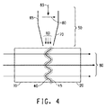
同様に、図4は、本発明の別の一実施形態を示している。2つの感光板(10および20)は、たとえばポリテトラフルオロエチレン(PTFE)でできたバッキング(30)上に並べて配置される。2つの板は、端部で互いに接触している(40)。記載の溶接線(40)の実質的に近傍の領域を局所加熱区域(45)と呼ぶ。この領域(45)は、マイクロ波放射(50)が当たることによる2つの板(10および20)の他の領域の何らかの形態の溶融または液化がより起こりやすい。この実施形態において、図4に示されるように、溶接線(40)はまっすぐではなく、不均一な形状を想定することができる。溶接線(40)を得るために2つの端部が一致するように、第2の感光板を切断することができる。マイクロ波装置(50)は、不均一な形状の溶接線(40)に沿って移動させ、溶接線上の特定の位置で所定の時間維持し、溶接線(40)に沿って移動させることで溶接を行うことができる。有効なシールが得られるように溶接線(40)に沿って移動させるために、マイクロ波装置をプログラムすることができる。 Similarly, FIG. 4 illustrates another embodiment of the present invention. The two photosensitive plates (10 and 20) are arranged side by side on a backing (30) made of, for example, polytetrafluoroethylene (PTFE). The two plates are in contact with each other at the ends (40). The region substantially near the described weld line (40) is referred to as the local heating zone (45). This region (45) is more susceptible to some form of melting or liquefaction of the other regions of the two plates (10 and 20) due to the microwave radiation (50) impinging. In this embodiment, as shown in FIG. 4, the weld line (40) is not straight and can assume a non-uniform shape. The second photosensitive plate can be cut so that the two ends coincide to obtain a weld line (40). The microwave device (50) is moved along the weld line (40) having a non-uniform shape, maintained at a specific position on the weld line for a predetermined time, and moved along the weld line (40). It can be performed. The microwave device can be programmed to move along the weld line (40) to obtain an effective seal.
本発明の方法は、感光板の化学線への像様露光の前に使用することができる。しかし、別の一実施形態においては、マイクロ波放射を用いて、像様露光した1つまたは複数の板を溶接することもできる。 The method of the present invention can be used prior to imagewise exposure of the photosensitive plate to actinic radiation. However, in another embodiment, microwave radiation can be used to weld one or more imagewise exposed plates.
一実施形態においては、マイクロ波放射は、以下:
約300MHz〜約30,000MHz;
約400MHz〜約24,000MHz;
約425MHz〜約950MHz;
約425MHz〜約450MHz;
約885MHz〜約925MHz;
約2400MHz〜約2600MHz;
約2435MHz〜約2460MHz;
約5,700MHz〜約5,900MHz;
約5,785MHz〜約5,810MHz;
約23,985MHz〜約24,010MHz
の好ましい周波数範囲内にある。
In one embodiment, the microwave radiation is:
About 300 MHz to about 30,000 MHz;
About 400 MHz to about 24,000 MHz;
About 425 MHz to about 950 MHz;
About 425 MHz to about 450 MHz;
About 885 MHz to about 925 MHz;
About 2400 MHz to about 2600 MHz;
About 2435 MHz to about 2460 MHz;
About 5,700 MHz to about 5,900 MHz;
About 5,785 MHz to about 5,810 MHz;
About 23,985 MHz to about 24,010 MHz
Within the preferred frequency range.
マイクロ波放射のさらに好ましい周波数としては433MHz、896MHz、915MHz、2450MHz、5800MHz、および24,000MHzが挙げられる。 More preferred frequencies for microwave radiation include 433 MHz, 896 MHz, 915 MHz, 2450 MHz, 5800 MHz, and 24,000 MHz.
一実施形態においては、マイクロ波放射露光の時間は、特定の位置において約1秒〜約120秒の範囲内である。好ましい一実施形態においては、マイクロ波放射曝露の時間は約1秒〜約20秒の範囲内である。露光のさらに好ましい範囲は約1秒〜10秒である。 In one embodiment, the time of microwave radiation exposure is in the range of about 1 second to about 120 seconds at a particular location. In a preferred embodiment, the time of microwave radiation exposure is in the range of about 1 second to about 20 seconds. A more preferable range of exposure is about 1 to 10 seconds.
一実施形態においては、供給されるマイクロ波出力は約100W〜2,000Wの範囲内である。本発明の好ましい一実施形態においては、供給されるマイクロ波出力は約400W〜約2500Wの範囲内である。さらに好ましい範囲においては、出力は約450W〜800Wである。 In one embodiment, the microwave power supplied is in the range of about 100W to 2,000W. In a preferred embodiment of the present invention, the microwave power supplied is in the range of about 400W to about 2500W. In a more preferred range, the output is about 450W to 800W.
感光性エレメントの概略
前述したように、本発明は、2つ以上の感光性エレメントの端部溶接に関する。好ましくは、端部溶接は、マイクロ波放射をエレメントの局所加熱区域に当てることによって行われ、その後、感光性エレメントを化学線に像様露光する。
Overview of Photosensitive Elements As described above, the present invention relates to end welding of two or more photosensitive elements. Preferably, end welding is performed by applying microwave radiation to the locally heated area of the element, after which the photosensitive element is imagewise exposed to actinic radiation.
端部で互いに溶接され、後にフレキソ印刷フォームの作製に使用される感光性エレメントは、光重合性組成物の少なくとも1つの層を含む。用語「感光性」は、化学線に応答して少なくとも1つの感光層が1つまたは複数の反応、特に光化学反応を開始することができる任意の系を含む。ある実施形態においては、感光性エレメントは、光重合性組成物層のための支持体を含む。ある実施形態においては、光重合性組成物層は、バインダーと、少なくとも1種類のモノマーと、光開始剤とを含む。バインダーは熱可塑性バインダーであってよい。光開始剤は、化学線に対する感受性を有する。本明細書全体にわたって、化学線は紫外線および/または可視光を含む。ある実施形態においては、感光性エレメントは、支持体の反対側で光重合性組成物層に隣接する化学線不透明材料の層を含む。別の実施形態においては、感光性エレメントは、光重合性組成物層に隣接するその場でのマスクとしての使用に好適な化学線不透明材料の画像を含む。 Photosensitive elements that are welded together at the ends and later used to make flexographic printing forms comprise at least one layer of photopolymerizable composition. The term “photosensitive” includes any system in which at least one photosensitive layer can initiate one or more reactions, particularly photochemical reactions, in response to actinic radiation. In some embodiments, the photosensitive element includes a support for the photopolymerizable composition layer. In some embodiments, the photopolymerizable composition layer includes a binder, at least one monomer, and a photoinitiator. The binder may be a thermoplastic binder. Photoinitiators are sensitive to actinic radiation. Throughout this specification actinic radiation includes ultraviolet and / or visible light. In certain embodiments, the photosensitive element includes a layer of actinic radiation opaque material adjacent to the photopolymerizable composition layer on the opposite side of the support. In another embodiment, the photosensitive element includes an image of an actinic radiation opaque material suitable for use as an in situ mask adjacent to the photopolymerizable composition layer.
特に記載のない限り、用語「感光性エレメント」は、印刷に適した表面を形成するための化学線への露光および処理が可能な印刷前駆体を含む。特に記載のない限り、「感光性エレメント」および「印刷フォーム」は、印刷に好適となる、または印刷に好適である任意の形態の要素または構造を含み、たとえば、限定するものではないが、平坦シート、板、継ぎ目のない連続形態、円筒形、スリーブ上の板、およびキャリア上の板を含む。感光性エレメントから得られる印刷フォームは、フレキソ印刷および活版印刷などの凸版印刷において最終的に使用される印刷用途を有することが意図される。凸版印刷は、画像領域から印刷フォームが印刷し、印刷フォームの画像領域は隆起しており、非画像領域はへこんでいる印刷方法である。 Unless otherwise stated, the term “photosensitive element” includes printing precursors that are capable of exposure to and treatment with actinic radiation to form a surface suitable for printing. Unless otherwise stated, “photosensitive element” and “printing form” include any form of element or structure suitable for printing or suitable for printing, for example, but not limited to, flat Includes sheets, plates, seamless continuous forms, cylinders, plates on sleeves, and plates on carriers. Printing forms obtained from photosensitive elements are intended to have printing applications that are ultimately used in letterpress printing such as flexographic printing and letterpress printing. Letterpress printing is a printing method in which a printing form is printed from an image area, the image area of the printing form is raised, and a non-image area is dented.
感光性エレメントは、光重合性組成物の少なくとも1つの層を含む。本明細書において使用される場合、用語「光重合性」は、光重合性、光架橋性、またはその両方である系を含むことを意図している。光重合性組成物層は、バインダーと、少なくとも1種類のモノマーと、光開始剤とを含む組成物から形成された固体エラストマー層である。光開始剤は、化学線に対する感受性を有する。本明細書全体にわたって、化学線は、紫外線および/または可視光を含む。光重合性組成物の固体層は、1つまたは複数の溶液および/または熱で処理されて、フレキソ印刷に適したレリーフが形成される。本明細書において使用される場合、用語「固体」は、画定された体積および形状を有し、その体積または形状を変化させる傾向にある力に抵抗する層の物理的状態を意味する。光重合性組成物の層は、約5℃〜約30℃の間の温度である室温において固体である。光重合性組成物の固体層は、重合(光硬化)する場合も、重合しない場合もあり、その両方である場合もある。 The photosensitive element includes at least one layer of a photopolymerizable composition. As used herein, the term “photopolymerizable” is intended to include systems that are photopolymerizable, photocrosslinkable, or both. The photopolymerizable composition layer is a solid elastomer layer formed from a composition containing a binder, at least one monomer, and a photoinitiator. Photoinitiators are sensitive to actinic radiation. Throughout this specification, actinic radiation includes ultraviolet and / or visible light. The solid layer of the photopolymerizable composition is treated with one or more solutions and / or heat to form a relief suitable for flexographic printing. As used herein, the term “solid” means a physical state of a layer that has a defined volume and shape and resists forces that tend to change its volume or shape. The layer of photopolymerizable composition is solid at room temperature, which is a temperature between about 5 ° C and about 30 ° C. The solid layer of the photopolymerizable composition may be polymerized (photocured), not polymerized, or both.
感光層は、ガラス転移温度で溶融または流動する。感光層の材料は、通常、固体と液体との間で明確な転移を示さない粘弾性材料であり、したがってガラス転移温度は固体状態と液体状態の間で明確な転移温度を有さない場合がある。そのガラス転移温度より低温に感光層を予備加熱することで、粘弾性材料の流動または溶融が回避される。層を軟化させ、および/または粘着性にするのに十分であるが、流動または溶融する閾値よりは低い任意の温度への感光層の予備加熱が好適となる。しかし、本明細書全体にわたって、用語「軟化」は、組成物が固体状態と液体状態との間で明確な転移温度を有しうるかどうかとは無関係に、予備加熱された感光層の挙動を表すために使用することができる。本発明の目的で感光層を「軟化」させるために広い温度範囲を使用することができる。端部のシールおよび融合は、プロセスの上首尾の作業中に、より低温でより遅くすることも、より高温でより速くすることもできる。 The photosensitive layer melts or flows at the glass transition temperature. The material of the photosensitive layer is usually a viscoelastic material that does not show a clear transition between solid and liquid, so the glass transition temperature may not have a clear transition temperature between the solid and liquid states. is there. By preheating the photosensitive layer below its glass transition temperature, the viscoelastic material is prevented from flowing or melting. Preheating the photosensitive layer to any temperature that is sufficient to soften and / or tackify the layer, but below the threshold to flow or melt, is preferred. However, throughout this specification, the term “softening” refers to the behavior of a preheated photosensitive layer, regardless of whether the composition may have a well-defined transition temperature between the solid state and the liquid state. Can be used for. A wide temperature range can be used to “soften” the photosensitive layer for purposes of the present invention. End seal and fusion can be slower at lower temperatures or faster at higher temperatures during successful operation of the process.
本発明のほとんどの場合で、マイクロ波放射でシールされた隣接する端部の継ぎ目または溶接線は、円筒形感光性エレメントの外面上に見ることができる。別の場合では、シールされた隣接する端部の継ぎ目または溶接線は、印刷中に識別できるようになる。感光層の隣接する端部の溶接とは、隣接する端部が出会う境界線、または継ぎ目、または溶接線が存在しないように、存在する場合には板上に現像されるレリーフ特徴に好ましくは干渉しないように、隣接する端部が互いに保持され結合して支持体上に連続相を形成することを意味する。積層および融合の後、感光層は感光性材料の連続体となり、感光性エレメントは継ぎ目がないと見なすことができる。 In most cases of the invention, adjacent end seams or weld lines sealed with microwave radiation can be seen on the outer surface of the cylindrical photosensitive element. In other cases, the seam or weld line at the adjacent end of the seal becomes distinguishable during printing. Welding of adjacent edges of the photosensitive layer preferably interferes with relief features that are developed on the plate, if present, so that there are no boundaries, seams, or weld lines where the adjacent edges meet. It means that the adjacent ends are held and bonded together to form a continuous phase on the support. After lamination and fusion, the photosensitive layer becomes a continuous body of photosensitive material and the photosensitive element can be considered seamless.
光重合性層中のバインダーは限定されるものではないが、1種類のポリマー、またはポリマー混合物であってよい。ある実施形態においては、バインダーは、エラストマー性バインダーである。別の実施形態においては、バインダーは、化学線に露光するとエラストマーになる。バインダーとしては、共役ジオレフィン炭化水素の天然または合成のポリマー、たとえばポリイソプレン、1,2−ポリブタジエン、1,4−ポリブタジエン、ブタジエン/アクリロニトリル、およびジエン/スチレン熱可塑性エラストマー性ブロックコポリマーが挙げられる。ある実施形態においては、バインダーは、A−B−A型ブロックコポリマー(ここで、Aは非エラストマー性ブロックを表し、Bはエラストマー性ブロックを表す)のofanである。非エラストマー性ブロックAは、ビニルポリマー、たとえばポリスチレンなどであってよい。エラストマー性ブロックBの例としては、ポリブタジエンおよびポリイソプレンが挙げられる。ある実施形態においては、エラストマー性バインダーとしては、ポリ(スチレン/イソプレン/スチレン)ブロックコポリマー、およびポリ(スチレン/ブタジエン/スチレン)ブロックコポリマーが挙げられる。A−B−A型ブロックコポリマーの非エラストマー対エラストマーの比率は、10:90〜35:65の範囲内とすることができる。バインダーは、水性溶剤、半水性溶剤、水、または有機溶剤の洗浄溶液に対して可溶性、膨潤性、または分散性であってよい。水性または半水性の現像液で処理することによって洗い落とすことが可能なエラストマー性バインダーは、Proskowの米国特許第4,177,074号明細書、Proskowの米国特許第4,431,723号明細書、Wornsの米国特許第4,517,279号明細書、Suzukiらの米国特許第5,679,485号明細書、Suzukiらの米国特許第5,830,621号明細書、およびSakuraiらの米国特許第5,863,704号明細書に開示されている。Chenの米国特許第4,323,636号明細書、Heinzらの米国特許第4,430,417号明細書、およびTodaらの米国特許第4,045,231号明細書において議論されているブロックコポリマーは、有機溶剤溶液で処理することによって洗い落とすことができる。一般に、洗浄現像(washout development)に好適なエラストマー性バインダーは、加熱後に光重合性組成物層の未重合領域が軟化、溶融、または流動する熱処理における使用にも好適である。バインダーは、感光性組成物の少なくとも50重量%の量で存在することが好ましい。 The binder in the photopolymerizable layer is not limited, but may be a single polymer or a polymer mixture. In some embodiments, the binder is an elastomeric binder. In another embodiment, the binder becomes an elastomer when exposed to actinic radiation. Binders include natural or synthetic polymers of conjugated diolefin hydrocarbons such as polyisoprene, 1,2-polybutadiene, 1,4-polybutadiene, butadiene / acrylonitrile, and diene / styrene thermoplastic elastomeric block copolymers. In some embodiments, the binder is an of ABA type block copolymer, where A represents a non-elastomeric block and B represents an elastomeric block. Non-elastomeric block A may be a vinyl polymer, such as polystyrene. Examples of the elastomeric block B include polybutadiene and polyisoprene. In some embodiments, elastomeric binders include poly (styrene / isoprene / styrene) block copolymers and poly (styrene / butadiene / styrene) block copolymers. The ratio of non-elastomer to elastomer of the ABA type block copolymer can be in the range of 10:90 to 35:65. The binder may be soluble, swellable, or dispersible in aqueous solvent, semi-aqueous solvent, water, or organic solvent cleaning solutions. Elastomeric binders that can be washed off by processing with an aqueous or semi-aqueous developer include Proskow U.S. Pat. No. 4,177,074, Proskow U.S. Pat. No. 4,431,723, Worns U.S. Pat. No. 4,517,279, Suzuki et al. U.S. Pat. No. 5,679,485, Suzuki et al. U.S. Pat. No. 5,830,621, and U.S. Pat. This is disclosed in US Pat. No. 5,863,704. Blocks discussed in Chen US Pat. No. 4,323,636, Heinz et al. US Pat. No. 4,430,417, and Toda et al. US Pat. No. 4,045,231. The copolymer can be washed off by treatment with an organic solvent solution. In general, elastomeric binders suitable for washout development are also suitable for use in heat treatments where the unpolymerized areas of the photopolymerizable composition layer soften, melt or flow after heating. The binder is preferably present in an amount of at least 50% by weight of the photosensitive composition.
本明細書において使用される場合、バインダーという用語は、コアシェルマイクロゲル、およびFrydらの米国特許第4,956,252号明細書およびQuinnらの米国特許第5,707,773号明細書に開示されるようなマイクロゲルと実施した(performed)高分子ポリマーとのブレンドを含んでいる。 As used herein, the term binder is disclosed in core-shell microgels and in Flyd et al. US Pat. No. 4,956,252 and Quinn et al. US Pat. No. 5,707,773. A blend of a microgel as per the above and a polymerized polymer.
使用できる他の好適な感光性エラストマーとしてはポリウレタンエラストマーが挙げられる。好適なポリウレタンエラストマーの一例は、(i)有機ジイソシアネートと、(ii)イソシアネート基と重合可能な少なくとも2つの遊離水素基を有し、1分子当たり少なくとも1つのエチレン性不飽和付加重合性基を有する少なくとも1種類の鎖延長剤と、(iii)500の最小分子量を有し、イソシアネート基と重合可能な少なくとも2つの遊離水素含有基を有する有機ポリオールとの反応生成物である。これらの材料の一部のより徹底的な説明に関しては米国特許第5,015,556号明細書を参照されたい。 Other suitable photosensitive elastomers that can be used include polyurethane elastomers. An example of a suitable polyurethane elastomer has (i) an organic diisocyanate and (ii) at least two free hydrogen groups polymerizable with isocyanate groups and at least one ethylenically unsaturated addition polymerizable group per molecule. A reaction product of at least one chain extender and (iii) an organic polyol having a minimum molecular weight of 500 and having at least two free hydrogen-containing groups polymerizable with an isocyanate group. See US Pat. No. 5,015,556 for a more thorough explanation of some of these materials.
光重合性組成物は、透明で曇ってない感光層が得られて程度までバインダーと相溶性である付加重合可能な少なくとも1種類の化合物を含有する。この付加重合可能な少なくとも1種類の化合物は、モノマーと記載される場合もある。光重合性組成物中に使用できるモノマーは、当技術分野において周知であり、そのようなものとしては、少なくとも1つの末端エチレン性基を有する付加重合エチレン性不飽和化合物が挙げられるが、これらに限定されるものではない。一般に、これらのモノマーは比較的低分子量(約30,000未満)である。ある実施形態においては、モノマーは約5000未満の比較的低分子量である。特に記載のない限り、分子量は重量平均分子量である。付加重合化合物は、オリゴマーであってもよく、1種類のオリゴマーまたはオリゴマー混合物であってよい。ある実施形態は、1000を超える分子量を有するポリアクリロール(polyacrylol)オリゴマーを含む。組成物は、1種類のモノマー、またはモノマーの組み合わせを含有することができる。モノマー化合物は、組成物の少なくとも5重量%、ある実施形態においては10〜20重量%の量で存在する。 The photopolymerizable composition contains at least one compound capable of addition polymerization that is compatible with the binder to the extent that a transparent, non-cloudy photosensitive layer is obtained. The at least one compound capable of addition polymerization may be described as a monomer. Monomers that can be used in the photopolymerizable composition are well known in the art and include, but are not limited to, addition-polymerized ethylenically unsaturated compounds having at least one terminal ethylenic group. It is not limited. Generally, these monomers are relatively low molecular weight (less than about 30,000). In some embodiments, the monomer has a relatively low molecular weight of less than about 5000. Unless otherwise stated, molecular weight is weight average molecular weight. The addition polymerization compound may be an oligomer or a single type of oligomer or mixture of oligomers. Some embodiments include polyacrylol oligomers having a molecular weight greater than 1000. The composition can contain a single monomer or a combination of monomers. The monomeric compound is present in an amount of at least 5% by weight of the composition, and in some embodiments 10-20% by weight.
好適なモノマーとしては、限定するものではないが、アルコールおよびポリオールのアクリレートモノエステル;アルコールおよびポリオールのアクリレートポリエステル;アルコールおよびポリオールのメタクリレートモノエステル;ならびにアルコールおよびポリオールのメタクリレートポリエステルが挙げられ;好適なアルコールおよびポリオールとしては、アルカノール、アルキレングリコール、トリメチロールプロパン、エトキシル化トリメチロールプロパン、ペンタエリスリトール、およびポリアクリロールオリゴマーが挙げられる。他の好適なモノマーとしては、イソシアネート、エステル、エポキシドなどのアクリレート誘導体およびメタクリレート誘導体が挙げられる。一官能性アクリレート、多官能性アクリレート、一官能性メタクリレート、および/または多官能性メタクリレートの組み合わせを使用することができる。好適なモノマーの別の例としては、イソシアネート、エステル、エポキシドなどのアクリレートおよびメタクリレート誘導体が挙げられる。ある最終用途の印刷フォームにおいては、エラストマー性をエレメントに付与するモノマーの使用が望ましい場合がある。エラストマー性モノマーの例としては、アクリル化液体ポリイソプレン、アクリル化液体ブタジエン、高ビニル含有量の液体ポリイソプレン、および高ビニル含有量の液体ポリブタジエン(すなわち1−2ビニル基の含有量が約20重量%を超える)が挙げられるが、これらに限定されるものではない。 Suitable monomers include, but are not limited to, alcohol and polyol acrylate monoesters; alcohol and polyol acrylate polyesters; alcohol and polyol methacrylate monoesters; and alcohol and polyol methacrylate polyesters; And polyols include alkanols, alkylene glycols, trimethylolpropane, ethoxylated trimethylolpropane, pentaerythritol, and polyacrylol oligomers. Other suitable monomers include acrylate and methacrylate derivatives such as isocyanates, esters and epoxides. Combinations of monofunctional acrylates, polyfunctional acrylates, monofunctional methacrylates, and / or polyfunctional methacrylates can be used. Other examples of suitable monomers include acrylate and methacrylate derivatives such as isocyanates, esters, epoxides and the like. In some end use printing forms, it may be desirable to use monomers that impart elastomeric properties to the element. Examples of elastomeric monomers include acrylated liquid polyisoprene, acrylated liquid butadiene, high vinyl content liquid polyisoprene, and high vinyl content liquid polybutadiene (ie, a content of 1-2 vinyl groups of about 20 weights). %), But is not limited thereto.
モノマーのさらなる例は、米国特許第2,927,024号明細書、Chenの米国特許第4,323,636号明細書;Frydらの米国特許第4,753,865号明細書;Frydらの米国特許第4,726,877号明細書,およびFeinbergらの米国特許第4,894,315号明細書にみることができる。 Further examples of monomers are described in US Pat. No. 2,927,024, Chen US Pat. No. 4,323,636; Fryd et al. US Pat. No. 4,753,865; U.S. Pat. No. 4,726,877 and Feinberg et al. U.S. Pat. No. 4,894,315.
光開始剤は、化学線に対して感受性であり、過剰に反応停止することなく1種類または複数種類のモノマーの重合を開始するフリーラジカルを生成する任意の1種類の化合物または化合物の組み合わせであってよい。任意の周知の種類の光開始剤、特にフリーラジカル光開始剤、たとえばキノン類、ベンゾフェノン類、ベンゾインエーテル類、アリールケトン類、過酸化物類、ビイミダゾール類、ベンジルジメチルケタール、ヒドロキシルアルキルフェニルアセトフェノン、ジアルコキシアセトフェノン、トリメチルベンゾイルホスフィンオキシド誘導体、アミノケトン類、ベンゾイルシクロヘキサノール、メチルチオフェニルモルホリノケトン類、モルホリノフェニルアミノケトン類、αハロゲンノアセトフェノン類(halogennoacetophenones)、オキシスルホニルケトン類、スルホニルケトン類、オキシスルホニルケトン類、ベンゾイルオキシムエステル類、チオキサントロン類(thioxanthrones)、ケトクマリン類、およびミヒラーケトンを使用することができる。あるいは、光開始剤は、放射線によって活性化する増感剤によってフリーラジカルが得られる場合に、化合物の1つからフリーラジカルが得られる化合物の混合物であってよい。好ましくは、主要な露光(ならびに後露光およびバックフラッシュ)のための光開始剤は、可視光または紫外線310〜400nmの間、好ましくは345〜365nmの間に対して感受性である。220〜300nmの間、好ましくは245〜265nmの間の放射線に対して感受性である第2の光開始剤が、場合により光重合性組成物中に存在することができる。処理後、板は、220〜300nmの間の放射線で仕上げをすることで、レリーフ表面を非粘着化することができる。第2の光開始剤によって、板の非粘着化に必要な仕上げ露光時間が減少する。光開始剤は、光重合性組成物の重量を基準として一般に0.001%〜10.0%の量で存在する。 A photoinitiator is any one compound or combination of compounds that is sensitive to actinic radiation and generates free radicals that initiate the polymerization of one or more monomers without excessive reaction termination. It's okay. Any well-known type of photoinitiator, in particular free radical photoinitiators such as quinones, benzophenones, benzoin ethers, aryl ketones, peroxides, biimidazoles, benzyldimethyl ketal, hydroxylalkylphenylacetophenone, Dialkoxyacetophenone, trimethylbenzoylphosphine oxide derivative, aminoketone, benzoylcyclohexanol, methylthiophenylmorpholinoketone, morpholinophenylaminoketone, α-halogenoacetophenones, oxysulfonyl ketones, sulfonyl ketones, oxysulfonyl ketone , Benzoyloxime esters, thioxanthrones, ketocumari It can be used like, and Michler's ketone. Alternatively, the photoinitiator may be a mixture of compounds that yield free radicals from one of the compounds when the free radicals are obtained by a sensitizer activated by radiation. Preferably, the photoinitiator for the main exposure (and post-exposure and backflash) is sensitive to visible light or ultraviolet light between 310-400 nm, preferably between 345-365 nm. A second photoinitiator that is sensitive to radiation between 220 and 300 nm, preferably between 245 and 265 nm may optionally be present in the photopolymerizable composition. After the treatment, the relief finish surface can be made non-tacky by finishing the plate with radiation of 220 to 300 nm. The second photoinitiator reduces the finish exposure time required to detack the plate. The photoinitiator is generally present in an amount of 0.001% to 10.0% based on the weight of the photopolymerizable composition.
光重合性組成物は、希望する最終的な性質に依存して他の添加剤を含有することができる。光重合性組成物の追加の添加剤としては、増感剤、可塑剤、レオロジー調整剤、熱重合抑制剤、着色剤、加工助剤、酸化防止剤、オゾン分解防止剤、線量、およびフィラーが挙げられる。 The photopolymerizable composition can contain other additives depending on the final properties desired. Additional additives for photopolymerizable compositions include sensitizers, plasticizers, rheology modifiers, thermal polymerization inhibitors, colorants, processing aids, antioxidants, antiozonants, doses, and fillers. Can be mentioned.
エラストマーのフィルム形成性を調節するために可塑剤が使用される。好適な可塑剤の例としては、脂肪族炭化水素油、たとえば、ナフテン系油およびパラフィン系油;液体ポリジエン、たとえば、液体ポリブタジエン;液体ポリイソプレン;ポリスチレン;ポリ−α−メチルスチレン;α−メチルスチレン−ビニルトルエンコポリマー;水素化ロジンのペンタエリスリトールエステル;ポリテルペン樹脂;およびエステル樹脂が挙げられる。一般に、可塑剤は約5000未満の分子量を有する液体であるが、最大で約30,000の分子量を有することができる。低分子量の可塑剤は、約30,000未満の分子量を含んでいる。 Plasticizers are used to adjust the film formability of the elastomer. Examples of suitable plasticizers include aliphatic hydrocarbon oils such as naphthenic oils and paraffinic oils; liquid polydienes such as liquid polybutadiene; liquid polyisoprene; polystyrene; poly-α-methylstyrene; α-methylstyrene. -Vinyltoluene copolymers; pentaerythritol esters of hydrogenated rosins; polyterpene resins; and ester resins. Generally, the plasticizer is a liquid having a molecular weight of less than about 5000, but can have a molecular weight of up to about 30,000. Low molecular weight plasticizers contain a molecular weight of less than about 30,000.
光重合性組成物層の厚さは、希望する印刷フォームの種類に依存して広範囲で変動させることができる。一実施形態においては、感光層は約0.015インチ〜約0.250インチ以上(約0.038〜約0.64cm以上)の厚さを有することができる。別の一実施形態においては、感光層は約0.107インチ〜約0.300インチ(約0.27〜約0.76cm)の厚さを有することができる。ある実施形態においては、感光層は約0.020〜0.067インチ(0.5mm〜1.7mm)の厚さを有することができる。さらに別の実施形態においては、感光層は約0.002インチ〜0.025インチ(0.051〜0.64mm)の厚さを有することができる。ある実施形態においては、得られる感光層の厚さは、スリーブ支持体上の連続感光層の厚さよりも厚い。 The thickness of the photopolymerizable composition layer can vary over a wide range depending on the type of printing form desired. In one embodiment, the photosensitive layer can have a thickness of about 0.015 inches to about 0.250 inches or more (about 0.038 to about 0.64 cm or more). In another embodiment, the photosensitive layer can have a thickness of about 0.107 inches to about 0.300 inches (about 0.27 to about 0.76 cm). In some embodiments, the photosensitive layer can have a thickness of about 0.020 to 0.067 inches (0.5 mm to 1.7 mm). In yet another embodiment, the photosensitive layer can have a thickness of about 0.002 inches to 0.025 inches (0.051 to 0.64 mm). In some embodiments, the resulting photosensitive layer is thicker than the continuous photosensitive layer on the sleeve support.
感光性エレメントは、感光性組成物の層に隣接する支持体を場合により含むことができる。支持体は、印刷フォームの製造に使用される感光性エレメントとともに従来使用される任意の材料または材料の組み合わせで構成されてよい。ある実施形態においては、支持体は、支持体を通過する「バックフラッシュ」露光に対応するため、化学線に対して透明である。好適な支持体材料の例としては、付加ポリマーおよび線状縮合ポリマーから形成されるものなどのポリマーフィルム、透明フォーム、および布、たとえばガラス繊維が挙げられる。特定の最終使用条件下では、金属支持体は放射線に対して透明ではないが、アルミニウム、鋼、およびニッケルなどの金属を支持体として使用することもできる。ある実施形態においては、支持体はポリエステルフィルムである。一実施形態においては、支持体はポリエチレンテレフタレートフィルムである。支持体は、シート形態であってもよいし、スリーブなどの円筒形であってもよい。スリーブは、印刷用スリーブの形成に従来使用される任意の材料または材料の組み合わせから形成されてよい。スリーブは、単層、多層、複合材料、または一体構造を有することができる。スリーブは、化学線に対して通常は透明であるポリマーフィルムで作製することができ、それによって円筒形印刷エレメント中のフロアを形成するためのバックフラッシュ露光に対応することができる。米国特許第5,301,610号明細書に開示されるように、多層スリーブは可撓性材料の層の間に接着層または接着テープを含むことができる。スリーブは、ニッケルまたはガラスエポキシなどの透明でない化学線を遮断する材料でできていてもよい。スリーブは、同じまたは異なっていてよく、フィラーおよび/または繊維が混入されていてよい樹脂組成物の1つまたは複数の層で構成されてもよい。樹脂組成物として好適な材料は限定されず、その例としては、エポキシ樹脂;ポリスチレンおよびポリビニル樹脂、たとえばポリ塩化ビニルおよびポリ酢酸ビニル;フェノール樹脂;ならびに芳香族アミン硬化エポキシ樹脂が挙げられる。樹脂組成物中に使用される繊維としては、たとえばガラス繊維、アラミド繊維、炭素繊維、金属繊維、およびセラミック繊維を挙げることができるが、これらに限定されるものではない。スリーブと併用される繊維としては、連続材料、織布、および/または巻き付け材料を挙げることができる。繊維強化された樹脂組成物で形成された支持体が複合スリーブの一例である。ある実施形態においては、支持体は0.002〜0.050インチ(0.0051〜0.127cm)の厚さを有する。スリーブは、約0.01〜約6.35mm以上の肉厚を有することができる。ある実施形態においては、スリーブは約0.25〜3mmの間の肉厚を有する。ある実施形態においては、スリーブは約10〜80ミル(0.25〜2.0mm)の間、別の実施形態においては10〜40ミル(0.25〜1.0mm)の間の肉厚を有する。 The photosensitive element can optionally include a support adjacent to the layer of photosensitive composition. The support may be composed of any material or combination of materials conventionally used with photosensitive elements used in the manufacture of printing forms. In certain embodiments, the support is transparent to actinic radiation to accommodate “backflash” exposure through the support. Examples of suitable support materials include polymer films, such as those formed from addition polymers and linear condensation polymers, transparent foams, and fabrics such as glass fibers. Under certain end-use conditions, the metal support is not transparent to radiation, but metals such as aluminum, steel, and nickel can also be used as the support. In some embodiments, the support is a polyester film. In one embodiment, the support is a polyethylene terephthalate film. The support may be in the form of a sheet or a cylinder such as a sleeve. The sleeve may be formed from any material or combination of materials conventionally used to form printing sleeves. The sleeve can have a single layer, multiple layers, a composite material, or a unitary structure. The sleeve can be made of a polymer film that is normally transparent to actinic radiation, thereby allowing for backflash exposure to form a floor in a cylindrical printing element. As disclosed in US Pat. No. 5,301,610, a multilayer sleeve can include an adhesive layer or adhesive tape between layers of flexible material. The sleeve may be made of a material that blocks non-transparent actinic radiation, such as nickel or glass epoxy. The sleeve may be the same or different and may be composed of one or more layers of a resin composition that may be mixed with fillers and / or fibers. Suitable materials for the resin composition are not limited, and examples include epoxy resins; polystyrene and polyvinyl resins, such as polyvinyl chloride and polyvinyl acetate; phenol resins; and aromatic amine-cured epoxy resins. Examples of the fiber used in the resin composition include, but are not limited to, glass fiber, aramid fiber, carbon fiber, metal fiber, and ceramic fiber. The fibers used in combination with the sleeve can include continuous materials, woven fabrics, and / or wound materials. A support formed of a fiber-reinforced resin composition is an example of a composite sleeve. In some embodiments, the support has a thickness of 0.002 to 0.050 inch (0.0051 to 0.127 cm). The sleeve can have a wall thickness of about 0.01 to about 6.35 mm or more. In some embodiments, the sleeve has a wall thickness between about 0.25 and 3 mm. In some embodiments, the sleeve has a wall thickness of between about 10-80 mils (0.25-2.0 mm) and in other embodiments between 10-40 mils (0.25-1.0 mm). Have.
場合により、エレメントは、支持体と光重合性組成物層との間に接着層を含むか、あるいは光重合性組成物層に隣接する支持体の表面は、支持体と光重合性組成物層との間に強い接着を得るために接着促進面を有する。 In some cases, the element includes an adhesive layer between the support and the photopolymerizable composition layer, or the surface of the support adjacent to the photopolymerizable composition layer is formed between the support and the photopolymerizable composition layer. In order to obtain strong adhesion between the two, an adhesion promoting surface is provided.
光重合性組成物層自体は、バインダー、モノマー、開始剤、および他の成分を混合することによって多くの方法で作製することができる。光重合性混合物からホットメルトを形成し、次にカレンダー加工によって所望の厚さにすることが好ましい。組成物の溶融、混合、脱気、および濾過の機能を行うために押出機を使用することができる。均一な厚さを実現するために、押出ステップをカレンダー加工ステップと組み合わせると好都合な場合があり、その場合、2つのシートの間、たとえば支持体および一時的なカバーシートとの間、または1つの平坦なシートと剥離ロールとの間で、高温混合物のカレンダー加工を行う。あるいは、材料を一時的な支持体の上に押出/カレンダー加工し、後に所望の最終支持体に積層することができる。エレメントは、好適な混合装置中で成分を配合し、次に好適な金型中で所望の形状に材料をプレスすることによって作製することもできる。材料は、一般に支持体とカバーシートとの間でプレスされる。成形ステップは、加圧および/または加熱を含むことができる。カバーシートは、感光性エレメントが形成されるときに光重合性組成物層に転写される1つまたは複数の追加層を含むことができる。円筒形の光重合性エレメントは、任意の好適な方法によって形成することができる。一実施形態においては、円筒形エレメントは、光重合性印刷版をキャリアまたは円筒形支持体、すなわちスリーブ上に巻き付け、版の端部を結合させて円筒形を形成することで形成することができる。円筒形の光重合性エレメントは、Cushnerらの米国特許第5,798,019号明細書に開示される方法および装置により作製することもできる。 The photopolymerizable composition layer itself can be made in many ways by mixing binders, monomers, initiators, and other components. It is preferred to form a hot melt from the photopolymerizable mixture and then to the desired thickness by calendering. An extruder can be used to perform the functions of melting, mixing, deaerating and filtering the composition. In order to achieve a uniform thickness, it may be advantageous to combine the extrusion step with a calendering step, in which case between two sheets, for example between a support and a temporary cover sheet, or one Calendering the high temperature mixture between the flat sheet and the release roll. Alternatively, the material can be extruded / calendered onto a temporary support and later laminated to the desired final support. The element can also be made by blending the components in a suitable mixing device and then pressing the material into the desired shape in a suitable mold. The material is generally pressed between the support and the cover sheet. The forming step can include pressing and / or heating. The cover sheet can include one or more additional layers that are transferred to the photopolymerizable composition layer when the photosensitive element is formed. The cylindrical photopolymerizable element can be formed by any suitable method. In one embodiment, the cylindrical element can be formed by wrapping a photopolymerizable printing plate on a carrier or cylindrical support, i.e. a sleeve, and joining the ends of the plate to form a cylinder. . Cylindrical photopolymerizable elements can also be made by the method and apparatus disclosed in US Pat. No. 5,798,019 to Cushner et al.
感光性エレメントは、少なくとも1つの光重合性組成物層を含み、したがって2層または多層構成であってよい。感光性エレメントは、感光層上または感光層に隣接して1つまたは複数の追加層を含むことができる。ほとんどの実施形態においては、1つまたは複数の追加の層は、支持体とは反対側の感光層の面上に存在する。追加層の例としては、保護層、キャッピング層、エラストマー層、障壁層、およびそれらの組み合わせが挙げられるが、これらに限定されるものではない。1つまたは複数の追加の層は、処理中に全体的または部分的に取り外し可能であり得る。追加の層の1つまたは複数は、光重合性組成物層を覆う、または部分的にのみ覆うことができる。 The photosensitive element includes at least one photopolymerizable composition layer and thus may be a two-layer or multi-layer configuration. The photosensitive element can include one or more additional layers on or adjacent to the photosensitive layer. In most embodiments, one or more additional layers are present on the side of the photosensitive layer opposite the support. Examples of additional layers include, but are not limited to, protective layers, capping layers, elastomeric layers, barrier layers, and combinations thereof. One or more additional layers may be fully or partially removable during processing. One or more of the additional layers can cover or only partially cover the photopolymerizable composition layer.
保護層は、光重合性組成物層の表面を保護し、これによって、感光性エレメントの像様露光に使用されるマスク材料を容易に除去することができる。感光性エレメントは、少なくとも1つの光重合性組成物層の上にエラストマー性キャッピング層を含むことができる。エラストマー性キャッピング層は、通常、光重合性組成物層のカレンダー加工中に感光性の印刷エレメントの一部となる多層カバー要素の一部である。エラストマー性キャッピング層として好適な多層カバー要素および組成物は、Gruetzmacherらの米国特許第4,427,759号明細書および米国特許第4,460,675号明細書に開示されている。ある実施形態においては、エラストマー性キャッピング層の組成物は、エラストマー性バインダー、ならびに場合によりモノマーおよび光開始剤および他の添加剤を含み、これらすべては、光重合性組成物層全体に使用されるものと同じ場合も異なる場合もある。エラストマー性キャッピング層は、光反応性成分を必ずしも含有しなくてもよいが、その層は最終的には、下にあるバルクの光重合性組成物層と接触するときに感光性となる。したがって、化学線に像様露光すると、エラストマー性キャッピング層は、重合または架橋が起こった硬化部分と、依然として重合していない、すなわち架橋していない未硬化または未照射部分とを有する。レリーフ表面を形成するために、処理によって、エラストマー性キャッピング層の未重合部分が、光重合性組成物層とともに除去される。化学線に露光したエラストマー性キャッピング層は、光重合性組成物層の重合領域の表面上に残存し、印刷版の実際の印刷される表面となる。 The protective layer protects the surface of the photopolymerizable composition layer, whereby the mask material used for imagewise exposure of the photosensitive element can be easily removed. The photosensitive element can include an elastomeric capping layer over at least one photopolymerizable composition layer. The elastomeric capping layer is usually part of a multilayer cover element that becomes part of the photosensitive printing element during calendering of the photopolymerizable composition layer. Multilayer cover elements and compositions suitable as elastomeric capping layers are disclosed in U.S. Pat. No. 4,427,759 and U.S. Pat. No. 4,460,675 to Gruetzmacher et al. In some embodiments, the elastomeric capping layer composition comprises an elastomeric binder, and optionally monomers and photoinitiators and other additives, all of which are used throughout the photopolymerizable composition layer. It can be the same or different. The elastomeric capping layer does not necessarily contain a photoreactive component, but the layer eventually becomes photosensitive when in contact with the underlying bulk photopolymerizable composition layer. Thus, upon imagewise exposure to actinic radiation, the elastomeric capping layer has a cured portion that has undergone polymerization or crosslinking and an uncured or unirradiated portion that is not yet polymerized, i.e., has not been crosslinked. To form the relief surface, the process removes unpolymerized portions of the elastomeric capping layer along with the photopolymerizable composition layer. The elastomeric capping layer exposed to actinic radiation remains on the surface of the polymerization region of the photopolymerizable composition layer and becomes the actual printed surface of the printing plate.
化学線不透明層は、レーザー放射線、通常は赤外レーザー放射線が、感光性エレメントのための画像のマスクを形成するために(従来の画像透過原稿またはフォトツールの代わりに)使用されるデジタルダイレクト刷版画像形成技術(digital direct−to−plate image technology)において使用される。化学線不透明層は、光重合性材料の感受性に対応する化学線に対して実質的に不透明である。デジタル方法では、レーザー放射線を用いて、光重合性組成物層上のマスク画像、または上に配置されるマスク画像がその場で形成される。マスク画像を形成するデジタル方法は、像様露光の前に感光性エレメントを作製するために1つまたは複数のステップが必要となる。一般に、その場でマスクを形成するデジタル方法は、放射線不透明層を、支持体とは反対側の感光性エレメントの表面から選択的に除去するか、表面に選択的に転写するかのいずれかである。化学線不透明層は、不透明層を選択的に除去または転写することができるレーザー放射線に対して感受性でもある。一実施形態においては、化学線不透明層は、赤外レーザー放射線に対して感受性である。感光性エレメント上に放射線不透明層を使用してマスクを形成する方法は限定されない。 Actinic opaque layers are digital direct prints where laser radiation, usually infrared laser radiation, is used (instead of conventional image-transparent originals or photo tools) to form image masks for photosensitive elements. Used in digital direct-to-plate image technology. The actinic radiation opaque layer is substantially opaque to actinic radiation that corresponds to the sensitivity of the photopolymerizable material. In digital methods, laser radiation is used to form a mask image on the photopolymerizable composition layer or a mask image disposed thereon in situ. Digital methods for forming mask images require one or more steps to produce a photosensitive element prior to imagewise exposure. In general, digital methods of forming the mask in situ involve either removing the radiation opaque layer selectively from the surface of the photosensitive element opposite the support or selectively transferring to the surface. is there. The actinic radiation opaque layer is also sensitive to laser radiation that can selectively remove or transfer the opaque layer. In one embodiment, the actinic radiation opaque layer is sensitive to infrared laser radiation. The method of forming a mask using a radiation opaque layer on the photosensitive element is not limited.
一実施形態においては、感光性エレメントは、上に配置された化学線不透明層を含むことができ、支持体の反対側の光重合性組成物層の表面全体を覆うまたは実質的に覆う。この実施形態においては、Fanの米国特許第5,262,275号明細書、Fanの米国特許第5,719,009号明細書、Fanの米国特許第6,558,876号明細書、Fanの欧州特許出願公開第0 741 330 A1号明細書、およびVan Zoerenの米国特許第5,506,086号明細書および米国特許第5,705,310号明細書に開示されるように、赤外レーザー放射線が、放射線不透明層を像様に除去し、すなわち消散または蒸発させて、その場でマスクが形成される。Van Zoerenの米国特許第5,705,310号明細書に開示されるように、感光性エレメントから材料が除去されるときにその材料を捕捉するために、レーザー露光中に、放射線不透明層に隣接する材料捕捉シートが存在することができる。感光性エレメントから除去されなかった放射線不透明層の部分のみが、エレメント上に残存してその場のマスクを形成する。 In one embodiment, the photosensitive element can include an actinic radiation opaque layer disposed thereon, covering or substantially covering the entire surface of the photopolymerizable composition layer opposite the support. In this embodiment, Fan US Pat. No. 5,262,275, Fan US Pat. No. 5,719,009, Fan US Pat. No. 6,558,876, Infrared lasers, as disclosed in European Patent Application 0 741 330 A1, and in US Pat. No. 5,506,086 by Van Zoren and US Pat. No. 5,705,310. The radiation removes the radiation opaque layer imagewise, ie dissipates or evaporates, and a mask is formed in situ. Adjacent to a radiation opaque layer during laser exposure to capture material as it is removed from the photosensitive element, as disclosed in US Pat. No. 5,705,310 to Van Zoren There may be a material capture sheet to do. Only those portions of the radiation opaque layer that have not been removed from the photosensitive element remain on the element to form an in-situ mask.
ある実施形態においては、化学線不透明層は、放射線不透明材料、赤外線吸収材料、および場合によりバインダーを含む。カーボンブラックおよび黒鉛などの暗色の無機顔料、顔料混合物、金属、および金属合金は、一般に、赤外線感受性材料および放射線不透明材料の両方として機能する。場合により使用されるバインダーは、限定するものではないが、自己酸化性ポリマー;非自己酸化性ポリマー;熱化学的に分解可能なポリマー;ブタジエンおよびイソプレンとスチレンおよび/またはオレフィンとのポリマーおよびコポリマー;熱分解性ポリマー;両性インターポリマー;ポリエチレンワックス、剥離層として従来使用されるポリアミド、ポリビニルアルコール、ヒドロキシアルキルセルロース、およびエチレンと酢酸ビニルとのコポリマーなどの材料;ならびにそれらの組み合わせなどのポリマー材料である。化学線不透明層の厚さは、感受性および不透明性の両方を最適化させる範囲内となるべきであり、一般に約20オングストローム〜約50マイクロメートルである。化学線不透明層は、化学線を効果的に遮断し、および下にある光重合性組成物層の重合を効果的に阻止するために、2.0を超える透過光学濃度を有するべきである。 In certain embodiments, the actinic radiation opaque layer includes a radiation opaque material, an infrared absorbing material, and optionally a binder. Dark inorganic pigments such as carbon black and graphite, pigment mixtures, metals, and metal alloys generally function as both infrared sensitive and radiation opaque materials. Optional binders include, but are not limited to, self-oxidizing polymers; non-self-oxidizing polymers; thermochemically degradable polymers; polymers and copolymers of butadiene and isoprene with styrene and / or olefins; Thermally decomposable polymers; amphoteric interpolymers; materials such as polyethylene wax, polyamides conventionally used as release layers, polyvinyl alcohol, hydroxyalkyl cellulose, and copolymers of ethylene and vinyl acetate; and polymer materials such as combinations thereof . The thickness of the actinic radiation opaque layer should be in a range that optimizes both sensitivity and opacity, and is generally from about 20 angstroms to about 50 micrometers. The actinic radiation opaque layer should have a transmission optical density greater than 2.0 in order to effectively block actinic radiation and effectively prevent polymerization of the underlying photopolymerizable composition layer.
感光性エレメントが円筒形である一実施形態においては、エレメントは、感光層(または存在する場合には別の層)の上に赤外線(IR)感光層をさらに含む。IR感光層は、感光性エレメントの一体型マスキング層を形成することができる。好ましいIR感光層は、化学線に対して不透明であり、すなわち少なくとも1.5の光学濃度を有し;好ましくは赤外レーザーを用いたアブレーションによって画像形成可能であり;処理中に除去可能である、すなわち現像液に対して可溶性または分散性である、または熱現像中に除去可能である。IR感光層は、波長(750〜20,000nmの間の赤外範囲において高い吸収を示す材料、たとえば、多置換フタロシアニン化合物、シアニン染料、メロシアニン染料など、無機顔料、たとえば、カーボンブラック、黒鉛、二酸化クロムなど、または金属、たとえばアルミニウム、銅などを含有する。赤外線吸収材料の量は、通常、層の全重量に対して0.1〜40重量%である。化学線を遮断するために望ましい光学濃度を実現するために、赤外感光層は、化学線の透過を妨害する材料を含有する。ある実施形態においては、光学濃度は2.0〜3.0の間となることができる。ある実施形態においては、光学濃度は2.6〜3.4の間となることができる。この化学線遮断材料は、赤外線吸収材料と同じ場合も異なる場合もあり、たとえば染料または顔料であってよく、特に前述の無機顔料であってよい。この材料の量は、通常、層の全重量に対して1〜70重量%である。赤外感光層は、場合により、ポリマーバインダー、たとえば、ニトロセルロース、アクリレートと、メタクリレートと、スチレンとのホモポリマーまたはコポリマー、ポリアミド、ポリビニルアルコールなどを含む。可塑剤、コーティング助剤などの他の補助剤も可能である。赤外感光層は、通常、感光層上の層として前述の成分の溶液または分散液をコーティングし、続いてそれを乾燥させることによって形成される。赤外感光層の厚さは、通常2nm〜50μm、好ましくは4nm〜40μmである。これらの赤外感光層およびそれらの形成は、たとえば国際公開第94/03838号パンフレットおよび国際公開第94/3839号パンフレットに詳細に記載されている。 In one embodiment where the photosensitive element is cylindrical, the element further comprises an infrared (IR) photosensitive layer over the photosensitive layer (or another layer, if present). The IR photosensitive layer can form an integral masking layer of the photosensitive element. Preferred IR-sensitive layers are opaque to actinic radiation, i.e. have an optical density of at least 1.5; preferably imageable by ablation with an infrared laser; removable during processing I.e., soluble or dispersible in the developer, or removable during thermal development. The IR photosensitive layer has a wavelength (a material exhibiting high absorption in the infrared range between 750 to 20,000 nm, for example, a polysubstituted phthalocyanine compound, a cyanine dye, a merocyanine dye, an inorganic pigment such as carbon black, graphite, Contains chromium, or metals such as aluminum, copper, etc. The amount of infrared absorbing material is typically 0.1 to 40% by weight, based on the total weight of the layer. In order to achieve density, the infrared sensitive layer contains a material that blocks transmission of actinic radiation, hi some embodiments, the optical density can be between 2.0 and 3.0. In embodiments, the optical density can be between 2.6 and 3.4 The actinic radiation blocking material may or may not be the same as the infrared absorbing material. For example, it may be a dye or a pigment, in particular an inorganic pigment as described above, and the amount of this material is usually 1 to 70% by weight relative to the total weight of the layer. Polymer binders such as homopolymers or copolymers of nitrocellulose, acrylate, methacrylate and styrene, polyamide, polyvinyl alcohol, etc. Other adjuvants such as plasticizers, coating aids are also possible. The photosensitive layer is usually formed by coating a solution or dispersion of the above-described components as a layer on the photosensitive layer, followed by drying.The thickness of the infrared photosensitive layer is usually 2 nm to 50 μm, These infrared photosensitive layers and the formation thereof are, for example, WO 94/03838. And it is described in detail in International Publication No. 94/3839 pamphlet.
円筒形エレメントを含む実施形態において、円筒形感光性エレメントは、フレキソ印刷に好適な印刷フォーム上にレリーフ表面を形成するための露光(像様露光および場合によりバックフラッシュ露光を含む)および処理の従来ステップを行うことによって、円筒形印刷フォームに変換される。 In embodiments that include a cylindrical element, the cylindrical photosensitive element is exposed to exposure (including imagewise exposure and optionally backflash exposure) and processing to form a relief surface on a printing form suitable for flexographic printing. By performing the steps, it is converted into a cylindrical print form.
この方法は、感光性組成物の層を提供するステップと、感光性組成物の層を円筒形支持体に取り付けるステップとを含む。ある実施形態においては、円筒形支持体の感光層への取り付けまたは接合または連結(「取り付け」)は、接着の目的で互いに接触させる前に、円筒形支持体および/または感光層を予備加熱するステップを含む(「予備加熱ステップ」)。別の実施形態においては、円筒形支持体の感光層への取り付けは、円筒形支持体および感光層の間に接着層を導入することで行われる(「接着ステップ」)。ある実施形態においては、接着ステップは予備加熱ステップとともに、取り付けの目的で使用される。提出された出願のIM1352には、感光層を円筒形支持体に取り付ける予備加熱ステップが詳細に記載されている。感光層を円筒形支持体に取り付ける方法は限定されない。本発明は、感光性エレメントを円筒形支持体に取り付けた後に、仕上げ媒体に曝露することによって、感光性エレメントの継ぎ目のない平滑な表面を得ることに関する。 The method includes providing a layer of photosensitive composition and attaching the layer of photosensitive composition to a cylindrical support. In certain embodiments, attachment or bonding or coupling ("attachment") of the cylindrical support to the photosensitive layer preheats the cylindrical support and / or photosensitive layer prior to contacting each other for adhesion purposes. Step (“preheating step”). In another embodiment, attachment of the cylindrical support to the photosensitive layer is accomplished by introducing an adhesive layer between the cylindrical support and the photosensitive layer (“adhesion step”). In some embodiments, the bonding step is used for attachment purposes along with a preheating step. The filed application IM1352 describes in detail the preheating step of attaching the photosensitive layer to a cylindrical support. The method for attaching the photosensitive layer to the cylindrical support is not limited. The present invention relates to obtaining a seamless smooth surface of a photosensitive element by attaching the photosensitive element to a cylindrical support and then exposing it to a finishing medium.
感光性に悪影響を与えることなく熱および圧力の影響下で接合可能なあらゆる熱可塑的に加工可能な固体感光層が使用に適している。感光層と円筒形支持体の外面との間の接着促進剤などの接着手段によって円筒形支持体に接着する、熱可塑性である必要はないが、熱可塑性であってよい感光層も含まれる。 Any thermoplastically processable solid photosensitive layer that can be joined under the influence of heat and pressure without adversely affecting photosensitivity is suitable for use. Also included are photosensitive layers that need not be thermoplastic, but need to be thermoplastic, which adhere to the cylindrical support by an adhesive means such as an adhesion promoter between the photosensitive layer and the outer surface of the cylindrical support.
熱可塑的に加工可能な固体感光層としては、特に、印刷レリーフ版の製造のためにそれ自体周知である、加熱すると軟化する、または加圧下で接着接合を示す固体ポリマー感光層が挙げられる。固体感光層は、少なくとも1種類の熱可塑性バインダー、モノマー、および光開始剤を含む。本明細書において使用される場合、用語「固体」は、画定された体積および形状を有し、その体積または形状を変化させる傾向にある力に抵抗する層の物理的状態を意味する。感光層は、一般に室温において固体であると見なされる。 The thermoplastically processable solid photosensitive layer includes in particular solid polymer photosensitive layers that are known per se for the production of printing relief plates, soften when heated, or exhibit adhesive bonding under pressure. The solid photosensitive layer includes at least one thermoplastic binder, a monomer, and a photoinitiator. As used herein, the term “solid” means a physical state of a layer that has a defined volume and shape and resists forces that tend to change its volume or shape. The photosensitive layer is generally considered solid at room temperature.
露光プロセスは、通常、背面露光および前面像様露光を含むが、前者は厳密には必要ではない。背面露光または「バックフラッシュ」は、像様露光の前、後、または最中に行うことができる。像様露光前のバックフラッシュが一般に好ましい。 The exposure process usually includes back exposure and front imagewise exposure, but the former is not strictly necessary. Back exposure or “backflash” can occur before, after, or during imagewise exposure. A backflash prior to imagewise exposure is generally preferred.
場合により、予備加熱または仕上げ媒体への曝露の後に、層中に重合材料の浅い層のフロアを形成するために、感光性全体を化学線に露光することができる。フロアを形成するためお全体的な露光は、多くの場合、バックフラッシュ露光と呼ばれる。層を支持体に接触させる前に感光層のバックフラッシュ露光が行われる一実施形態において、形成されるフロアは支持体に隣接するため、バックフラッシュ露光は感光層の接触面に対して行われる。ある実施形態においては、バックフラッシュ露光は、シート支持体(存在する場合)が感光層の接触面から除去された後に行われる。別の実施形態においては、バックフラッシュ露光は、シート支持体(存在する場合)が感光層の接触面から除去される前に行われる。バックフラッシュ時間は数秒〜約10分の範囲とすることができる。バックフラッシュ露光は、感光層を増感させ、ハイライトドット解像度に役立ち、印刷フォームのレリーフの深さも確立することができる。フロアによって、より良い機械的完全性が感光性エレメントに付与される。ある実施形態においては、円筒形支持体が化学線に対して透明である場合、バックフラッシュ露光は、円筒形感光性エレメントが形成された後に行うことができる。この場合、フロアを形成するための露光は、感光層の支持体への接着を改善することもできる。ある実施形態においては、バックフラッシュ露光は、円筒形感光性エレメントの形成の後であるが、円筒形感光性エレメントの継ぎ目のない平滑な表面を形成するために光重合性層の一部を除去するための仕上げ媒体への曝露の前に行うことができる。ある実施形態においては、バックフラッシュ露光は、円筒形感光性エレメントが形成された後で、円筒形感光性エレメントの継ぎ目のない平滑な表面を形成するために光重合性層の一部を感光性エレメントから除去するための仕上げ媒体への円筒形感光性エレメントの曝露のステップの後に行うことができる。バックフラッシュ露光は、一般に、レリーフフォームを形成するための感光性エレメントの化学線への露光の前に行われることに留意されたい。同様に、一実施形態においては、光重合性層の一部を感光性エレメントから除去するための仕上げ媒体への曝露のステップは、一般に、レリーフフォームを形成するための感光性エレメントの化学線への露光の前に行われることにも留意されたい。しかし、別の一実施形態においては、光重合性層の一部を感光性エレメントから除去するための仕上げ媒体への円筒形感光性エレメントの曝露のステップは、レリーフフォームを形成するための感光性エレメントの化学線への露光の後に行うことができる。 Optionally, the entire photosensitivity can be exposed to actinic radiation to form a shallow layer floor of polymeric material in the layer after preheating or exposure to the finishing medium. The overall exposure to form the floor is often referred to as backflash exposure. In one embodiment where the backflush exposure of the photosensitive layer is performed before contacting the layer to the support, the backflash exposure is performed on the contact surface of the photosensitive layer because the floor formed is adjacent to the support. In some embodiments, the backflash exposure occurs after the sheet support (if present) is removed from the contact surface of the photosensitive layer. In another embodiment, the backflash exposure is performed before the sheet support (if present) is removed from the contact surface of the photosensitive layer. The backflush time can range from a few seconds to about 10 minutes. Backflash exposure sensitizes the photosensitive layer, helps highlight dot resolution, and can also establish the relief depth of the printing form. The floor imparts better mechanical integrity to the photosensitive element. In some embodiments, if the cylindrical support is transparent to actinic radiation, the backflash exposure can be performed after the cylindrical photosensitive element is formed. In this case, the exposure for forming the floor can also improve the adhesion of the photosensitive layer to the support. In some embodiments, the backflash exposure is after formation of the cylindrical photosensitive element, but removes a portion of the photopolymerizable layer to form a seamless smooth surface of the cylindrical photosensitive element. Can be done prior to exposure to the finishing media. In some embodiments, the backflash exposure is performed after the cylindrical photosensitive element is formed, and a portion of the photopolymerizable layer is photosensitive to form a seamless smooth surface of the cylindrical photosensitive element. This can be done after the step of exposing the cylindrical photosensitive element to the finishing medium for removal from the element. Note that the backflash exposure is generally performed prior to exposure of the photosensitive element to actinic radiation to form a relief foam. Similarly, in one embodiment, the step of exposing to a finishing medium to remove a portion of the photopolymerizable layer from the photosensitive element generally involves actinic radiation of the photosensitive element to form a relief foam. Note also that this is done prior to the exposure. However, in another embodiment, the step of exposing the cylindrical photosensitive element to the finishing media to remove a portion of the photopolymerizable layer from the photosensitive element comprises the step of photosensitive to form a relief foam. This can be done after exposure of the element to actinic radiation.
像様露光後、感光層の放射線に露光した領域は不溶性状態に変化し、層の未露光領域では顕著な重合および架橋は起こらない。任意の従来の化学線源をこの露光に使用することができる。好適な放射線源の例としては、キセノンランプ、水銀蒸気ランプ、炭素アークランプ、アルゴングローランプ、UV線を発する蛍光物質と電子フラッシュ装置とを有する蛍光灯、および写真用フラッドランプが挙げられる。通常、水銀蒸気アークまたは太陽灯を、感光性エレメントから約1.5〜約60インチ(約3.8〜約153cm)の距離で使用することができる。これらの放射線源は、一般に310〜400nmの間の長波UV線を放出する。放射線強度およびスペクトルエネルギー分布、感光性エレメントからの距離、ならびに光重合性材料の性質および量、露光時間は数秒から数分で変動させることができる。 After imagewise exposure, the areas of the photosensitive layer exposed to radiation change to an insoluble state and no significant polymerization and crosslinking occurs in the unexposed areas of the layer. Any conventional source of actinic radiation can be used for this exposure. Examples of suitable radiation sources include xenon lamps, mercury vapor lamps, carbon arc lamps, argon glow lamps, fluorescent lamps having a fluorescent material emitting UV radiation and an electronic flash device, and photographic flood lamps. Typically, a mercury vapor arc or sunlamp can be used at a distance of about 1.5 to about 60 inches (about 3.8 to about 153 cm) from the photosensitive element. These radiation sources emit long wave UV radiation generally between 310-400 nm. The radiation intensity and spectral energy distribution, the distance from the photosensitive element, and the nature and amount of the photopolymerizable material, the exposure time can be varied from seconds to minutes.
像様露光は、画像を有するフォトマスクを介して感光性エレメントを露光することによって行うことができる。フォトマスクは、独立したフィルム、すなわち、画像を有する透過原稿またはフォトツール、たとえばハロゲン化銀フィルムであってよいし、またはフォトマスクは、前述のように感光性エレメントと一体となっていてもよい。フォトマスクが独立したフィルムである場合、場合により使用されるカバーシートは、通常、像様露光の前に除去され、感光性エレメント上に剥離層が残る。通常の真空プロセスによって、たとえば一般的な真空フレームを使用することによって、フォトマスクを感光性エレメントの剥離層と密接に接触させる。したがって、感光性エレメントとフォトマスクとの間の実質的に均一で徹底的な接触を許容される時間で実現することができる。 Imagewise exposure can be performed by exposing the photosensitive element through a photomask having an image. The photomask may be a separate film, i.e. a transparent original or phototool with an image, such as a silver halide film, or the photomask may be integral with the photosensitive element as described above. . If the photomask is a separate film, the optionally used cover sheet is usually removed prior to imagewise exposure, leaving a release layer on the photosensitive element. The photomask is brought into intimate contact with the release layer of the photosensitive element by a normal vacuum process, for example by using a common vacuum frame. Thus, a substantially uniform and thorough contact between the photosensitive element and the photomask can be achieved in a time allowed.
円筒形感光性エレメント上に一体化されたフォトマスクを形成することが好ましい。特に好ましい一実施形態においては、感光性エレメントは、一体化されたフォトマスクとなるIR感光層を含む。IR感光層を、IRレーザー放射線に像様露光することで、感光性エレメント上にフォトマスクが形成される。赤外レーザーの露光は、750〜20,000nmの範囲内で発光する様々な種類の赤外レーザーを用いて行うことができる。780〜2,000nmの範囲内で発光するダイオードレーザー、および1064nmで発光するNd:YAGレーザーなどの赤外レーザーが好ましい。いわゆるデジタル画像形成においては、放射線不透明層を赤外レーザー放射線に像様露光することで、光重合性組成物層の上に存在または配置される画像、すなわちインサイチュマスクが形成される。Fanの米国特許第5,262,275号明細書および米国特許第5,719,009号明細書;ならびにFanの欧州特許第0 741 330 B1号明細書に開示されるように、赤外レーザー放射線によって、赤外感光層(すなわち、放射線不透明層)を光重合性組成物層から選択的に除去、たとえば消散または蒸発させることができる。一体化したフォトマスクは、後のUV前露光、化学線への主要な像様露光、および現像のステップで、感光性エレメント上に残存する。 An integrated photomask is preferably formed on the cylindrical photosensitive element. In one particularly preferred embodiment, the photosensitive element includes an IR photosensitive layer that provides an integrated photomask. A photomask is formed on the photosensitive element by imagewise exposing the IR photosensitive layer to IR laser radiation. The infrared laser exposure can be performed using various types of infrared lasers that emit light within a range of 750 to 20,000 nm. Infrared lasers such as diode lasers emitting in the range of 780 to 2,000 nm and Nd: YAG lasers emitting at 1064 nm are preferred. In so-called digital imaging, the radiation opaque layer is imagewise exposed to infrared laser radiation to form an image that is present or disposed on the photopolymerizable composition layer, ie, an in situ mask. Infrared laser radiation as disclosed in Fan US Pat. No. 5,262,275 and US Pat. No. 5,719,009; and Fan EP 0 741 330 B1. Can selectively remove, eg, dissipate or evaporate, the infrared sensitive layer (ie, the radiation opaque layer) from the photopolymerizable composition layer. The integrated photomask remains on the photosensitive element in subsequent UV pre-exposure, main imagewise exposure to actinic radiation, and development steps.
別の一実施形態においては、マスクはデジタル方式で形成することができる。インサイチュマスクのデジタル形成の場合、感光性エレメントは、最初は化学線不透明層を含まない。通常は光重合性組成物層である、支持体の反対側の感光性エレメントの表面に放射線不透明層が隣接するように、放射線不透明層を有する別のエレメントと感光性エレメントとの組立体を形成する(存在する場合、感光性エレメントに関連するカバーシートは、通常、組立体を形成する前に除去される)。別のエレメントは、デジタル露光プロセスに役立つ放出層または加熱層などの1つまたは複数の他の層を含むことができる。これに関して、放射線不透明層は、赤外線に対して感受性でもある。Fanらの米国特許第5,607,814号明細書、ならびにBlanchettの米国特許第5,766,819号明細書、米国特許第5,840,463号明細書、および欧州特許出願公開第0 891 877 A号明細書に開示されるように、組立体に赤外レーザー放射線を像様露光することで、放射線不透明層を選択的に転写するか、放射線不透明層の接着バランスを選択的に変化させて、光重合性組成物層上に存在するまたは配置される画像を形成する。像様転写プロセスの結果、放射線不透明層の転写された部分のみが感光性エレメント上に存在して、インサイチュマスクを形成する。 In another embodiment, the mask can be formed digitally. In the case of digital formation of an in situ mask, the photosensitive element does not initially contain an actinic radiation opaque layer. Forms an assembly of another element with a radiation opaque layer and a photosensitive element so that the radiation opaque layer is adjacent to the surface of the photosensitive element opposite the support, usually a photopolymerizable composition layer (If present, the cover sheet associated with the photosensitive element is typically removed prior to forming the assembly). Another element can include one or more other layers, such as a release layer or a heating layer, useful in a digital exposure process. In this regard, the radiation opaque layer is also sensitive to infrared radiation. Fan et al., US Pat. No. 5,607,814, and Blanchett, US Pat. No. 5,766,819, US Pat. No. 5,840,463, and EP-A-0 891. As disclosed in 877 A, the assembly is imagewise exposed to infrared laser radiation to selectively transfer the radiation opaque layer or to selectively change the adhesion balance of the radiation opaque layer. To form an image present or disposed on the photopolymerizable composition layer. As a result of the imagewise transfer process, only the transferred portion of the radiation opaque layer is present on the photosensitive element to form an in situ mask.
別の一実施形態においては、感光性エレメント上にインクジェットインクの形態で放射線不透明材料を像様塗布することで、デジタルマスク形成を行うことができる。インクジェットインクの像様塗布は、光重合性組成物層上に直接行うことができるし、感光性エレメント上の別の層上の光重合性組成物層の上に配置することもできる。デジタルマスク形成を行うことができる別の考慮される方法は、別個のキャリア上に放射線不透明層のマスク画像を形成する方法である。ある実施形態においては、別個のキャリアは、レーザー放射線に像様露光して放射線不透明材料が選択的に除去され画像が形成された放射線不透明層を含む。次に、熱および/または圧力を加えることで、キャリア上のマスク画像を、支持体とは反対側の光重合性組成物層の表面に転写する。光重合性組成物層は通常は粘着性であり、転写された画像を保持する。次に、前露光および/または像様露光の前に別個のキャリアをエレメントから除去することができる。別個のキャリアは、レーザー放射線に像様露光して放射線不透明材料が選択的に除去され画像が形成される赤外感光層を有することができる。この種類のキャリアの一例は、Rexam,IncのLaserMask(登録商標)画像フィルムである。 In another embodiment, digital mask formation can be performed by imagewise applying a radiation opaque material in the form of an inkjet ink on a photosensitive element. Imagewise application of the inkjet ink can be performed directly on the photopolymerizable composition layer or can be disposed on the photopolymerizable composition layer on another layer on the photosensitive element. Another contemplated method by which digital mask formation can be performed is to form a mask image of a radiation opaque layer on a separate carrier. In some embodiments, the separate carrier includes a radiation opaque layer imagewise exposed to laser radiation to selectively remove the radiation opaque material and form an image. Next, by applying heat and / or pressure, the mask image on the carrier is transferred to the surface of the photopolymerizable composition layer opposite to the support. The photopolymerizable composition layer is usually tacky and retains the transferred image. The separate carrier can then be removed from the element prior to pre-exposure and / or imagewise exposure. The separate carrier can have an infrared photosensitive layer that is imagewise exposed to laser radiation to selectively remove the radiation opaque material and form an image. An example of this type of carrier is LaserMask® image film from Rexam, Inc.
感光性印刷エレメントは、エレメントの最上層の上に一時的なカバーシートを含むこともでき、これは印刷フォームの作製前に除去される。カバーシートの目的の1つは、保管および取り扱い中の感光性印刷エレメントの最上層を保護することである。カバーシートに好適な材料の例としては、ポリスチレン、ポリエチレン、ポリプロピレン、ポリカーボネート、フルオロポリマー、ポリアミド、またはポリエステルの薄いフィルムが挙げられ、これに剥離層を下塗りすることができる。カバーシートは、好ましくはMylar(登録商標)ポリエチレンテレフタレートフィルムなどのポリエステルフィルムから製造される。 The photosensitive printing element can also include a temporary cover sheet on the top layer of the element, which is removed prior to making the printing form. One purpose of the cover sheet is to protect the top layer of the photosensitive printing element during storage and handling. Examples of suitable materials for the cover sheet include thin films of polystyrene, polyethylene, polypropylene, polycarbonate, fluoropolymer, polyamide, or polyester, which can be primed with a release layer. The cover sheet is preferably manufactured from a polyester film, such as Mylar® polyethylene terephthalate film.
画像を有するマスクを介したUV線への全体露光の後、感光性エレメントは、光重合性組成物層中の未重合領域を除去するために処理され、それによってレリーフ画像が形成される。本発明の場合、感光性印刷エレメントの処理は、1つまたは複数の熱処理および/または1つまたは複数の溶剤系処理(湿式処理)を含む。たとえば、光重合性組成物層の熱現像では、光重合性組成物層を、未重合領域が溶融または軟化する現像温度まで加熱し、現像媒体の吸収材料と接触させて、未重合材料を吸い取る。 After total exposure to UV radiation through a mask having an image, the photosensitive element is processed to remove unpolymerized areas in the photopolymerizable composition layer, thereby forming a relief image. In the case of the present invention, the processing of the photosensitive printing element comprises one or more heat treatments and / or one or more solvent-based processing (wet processing). For example, in the thermal development of the photopolymerizable composition layer, the photopolymerizable composition layer is heated to a development temperature at which the unpolymerized region melts or softens, and is brought into contact with the absorbing material of the development medium to absorb the unpolymerized material. .
感光性エレメントの露光(および処理)の後の印刷フォームは、デュロメーターが約20〜約85のショアAである。ショアデュロメーターは、押し込みに対する材料の抵抗性の尺度の1つである。ショアAのデュロメーターは、軟質ゴムまたはエラストマー材料に典型的に使用される尺度であり、値が大きいほど、貫入に対する抵抗性が大きい。一実施形態においては、印刷フォームはショアAデュロメーターが約50未満〜約20である。別の一実施形態においては、印刷フォームはショアAデュロメーターが約40未満〜約25である。別の一実施形態においては、印刷フォームはショアAデュロメーターが約35未満〜約30である。ショアAデュロメーターが約40未満の印刷フォームは、段ボール板紙への印刷に特に適している。印刷フォームのデュロメーターは、DIN 53,505またはASTM D2240−00に記載の標準手順により測定することができる。ある実施形態においては、印刷フォームは、印刷フォームと同じまたは異なる弾力性を有するキャリア上に搭載することができる。キャリアの弾力性は、全体の印刷フォームパッケージ(即ちキャリアおよび印刷フォーム)の全体的な弾力性に影響を与えることがあり、その結果パッケージのデュロメーターが印刷フォームと異なる場合がある。 The printed form after exposure (and processing) of the photosensitive element is Shore A with a durometer of about 20 to about 85. The Shore Durometer is one measure of material resistance to indentation. The Shore A durometer is a measure typically used for soft rubber or elastomeric materials, the higher the value, the greater the resistance to penetration. In one embodiment, the printing form has a Shore A durometer of less than about 50 to about 20. In another embodiment, the printing form has a Shore A durometer of less than about 40 to about 25. In another embodiment, the printing form has a Shore A durometer of less than about 35 to about 30. Printing forms with a Shore A durometer of less than about 40 are particularly suitable for printing on corrugated paperboard. The durometer of the printed form can be measured by standard procedures described in DIN 53,505 or ASTM D2240-00. In some embodiments, the printing form can be mounted on a carrier that has the same or different elasticity as the printing form. The elasticity of the carrier can affect the overall elasticity of the entire printing form package (ie carrier and printing form), so that the durometer of the package can be different from the printing form.
実験
実施例1
2つのCyrel(登録商標)感光板(E.I.du Pont de Nemours&Co.Wilmington,Del.製)を並べて配置し、溶接される端部を接近させて配置した。2つの板の上に中程度の水平力を加えて、板をその場所に維持した。板をTeflon(登録商標)バッキングまたは支持体上に搭載した。
Experimental Example 1
Two Cyrel® photosensitive plates (E. I. du Pont de Nemours & Co. Wilmington, Del.) Were placed side by side and the welded ends were placed close together. A moderate horizontal force was applied on the two plates to keep the plates in place. The plate was mounted on a Teflon® backing or support.
接近するマイクロ波放射の焦点に所望の溶接線が存在するように、アルミニウム集中導波管アプリケーターを含むマイクロ波放射装置を、Cyrel(登録商標)板の上に配置した。アプリケーターは86mm×6mmの開口部を有した。導波管接合部から開口部までの焦点位置の長さは90mmであった。アプリケーターは、86mm×430mmの断面寸法を有する標準的なWR−340導波管に取り付けた。マイクロ波出力源は、Astex,Inc.製造のModel No.AX2115であり、最大出力は1500W、周波数は2.450GHzであり、Astex製造のマグネトロン源のモデル番号SXRHAに接続した。マイクロ波導波管はTE10モードで動作させた。マイクロ波出力は500Wに調整した。マイクロ波放射を4秒間当てた。 A microwave radiation device, including an aluminum concentrated waveguide applicator, was placed on the Cyrel® plate so that the desired weld line was at the focal point of the microwave radiation that was approaching. The applicator had an opening of 86 mm x 6 mm. The length of the focal position from the waveguide junction to the opening was 90 mm. The applicator was attached to a standard WR-340 waveguide having a cross-sectional dimension of 86 mm × 430 mm. Microwave output sources are available from Astex, Inc. Manufacture Model No. AX2115, maximum power 1500W, frequency 2.450GHz, connected to model number SXRHA of magnetron source manufactured by Astex. The microwave waveguide was operated in TE 10 mode. The microwave output was adjusted to 500W. Microwave radiation was applied for 4 seconds.
表1は上記実験の結果を示している。2つの板は首尾良く溶接された。2つのCyrel(登録商標)板の間の溶接線は見ることができた。しかし、溶接プロセスによる圧痕は存在しなかった。 Table 1 shows the results of the above experiment. The two plates were successfully welded. The weld line between the two Cyrel® plates could be seen. However, there was no indentation due to the welding process.
実施例2
2つのCyrel(登録商標)感光板(E.I.du Pont de Nemours&Co.Wilmington,Del.製)を並べて配置し、溶接される端部を接近させて配置した。2つの板の上に中程度の水平力を加えて、板をその場所に維持した。板をTeflon(登録商標)バッキングまたは支持体上に搭載した。
Example 2
Two Cyrel® photosensitive plates (E. I. du Pont de Nemours & Co. Wilmington, Del.) Were placed side by side and the welded ends were placed close together. A moderate horizontal force was applied on the two plates to keep the plates in place. The plate was mounted on a Teflon® backing or support.
接近するマイクロ波放射の焦点に所望の溶接線が存在するように、アルミニウム集中導波管アプリケーターを含むマイクロ波放射装置を、Cyrel(登録商標)板の上に配置した。アプリケーターは86mm×6mmの開口部を有した。導波管接合部から開口部までの焦点位置の長さは90mmであった。アプリケーターは、86mm×430mmの断面寸法を有する標準的なWR−340導波管に取り付けた。マイクロ波出力源は、Astex,Inc.製造のModel No.AX2115であり、最大出力は1500W、周波数は2.450GHzであり、Astex製造のマグネトロン源のモデル番号SXRHAに接続した。マイクロ波導波管はTE10モードで動作させた。マイクロ波出力は500Wに調整した。マイクロ波放射を6秒間当てた。 A microwave radiation device, including an aluminum concentrated waveguide applicator, was placed on the Cyrel® plate so that the desired weld line was at the focal point of the microwave radiation that was approaching. The applicator had an opening of 86 mm x 6 mm. The length of the focal position from the waveguide junction to the opening was 90 mm. The applicator was attached to a standard WR-340 waveguide having a cross-sectional dimension of 86 mm × 430 mm. Microwave output sources are available from Astex, Inc. Manufacture Model No. AX2115, maximum power 1500W, frequency 2.450GHz, connected to model number SXRHA of magnetron source manufactured by Astex. The microwave waveguide was operated in TE 10 mode. The microwave output was adjusted to 500W. Microwave radiation was applied for 6 seconds.
表1は上記実験の結果を示している。2つの板は首尾良く溶接された。2つのCyrel(登録商標)板の間の溶接線は見ることができたが、実施例1の溶接線と比較するとはるかにわかりにくかった。また、溶接プロセスによる圧痕は存在しなかった。Teflon(登録商標)バッキングに板が粘着することで、Cyrel(登録商標)板上にわずかな変色が観察された。 Table 1 shows the results of the above experiment. The two plates were successfully welded. Although the weld line between the two Cyrel® plates could be seen, it was much less obvious when compared to the weld line of Example 1. Also, there was no indentation due to the welding process. Slight discoloration was observed on the Cyrel® plate due to the plate sticking to the Teflon® backing.
実施例3
2つのCyrel(登録商標)感光板(E.I.du Pont de Nemours&Co.Wilmington,Del.製)を並べて配置し、溶接される端部を接近させて配置した。2つの板の上に中程度の水平力を加えて、板のその場所に維持した。板をTeflon(登録商標)バッキングまたは支持体上に搭載した。
Example 3
Two Cyrel® photosensitive plates (E. I. du Pont de Nemours & Co. Wilmington, Del.) Were placed side by side and the welded ends were placed close together. A moderate horizontal force was applied on the two plates to keep it in place on the plates. The plate was mounted on a Teflon® backing or support.
接近するマイクロ波放射の焦点に所望の溶接線が存在するように、アルミニウム集中導波管アプリケーターを含むマイクロ波放射装置を、Cyrel(登録商標)板の上に配置した。アプリケーターは86mm×6mmの開口部を有した。導波管接合部から開口部までの焦点位置の長さは90mmであった。アプリケーターは、86mm×430mmの断面寸法を有する標準的なWR−340導波管に取り付けた。マイクロ波出力源は、Astex,Inc.製造のModel No.AX2115であり、最大出力は1500W、周波数は2.450GHzであり、Astex製造のマグネトロン源のモデル番号SXRHAに接続した。マイクロ波導波管はTE10モードで動作させた。マイクロ波出力は750Wに調整した。マイクロ波放射を8秒間当てた。 A microwave radiation device, including an aluminum concentrated waveguide applicator, was placed on the Cyrel® plate so that the desired weld line was at the focal point of the microwave radiation that was approaching. The applicator had an opening of 86 mm x 6 mm. The length of the focal position from the waveguide junction to the opening was 90 mm. The applicator was attached to a standard WR-340 waveguide having a cross-sectional dimension of 86 mm × 430 mm. Microwave output sources are available from Astex, Inc. Manufacture Model No. AX2115, maximum power 1500W, frequency 2.450GHz, connected to model number SXRHA of magnetron source manufactured by Astex. The microwave waveguide was operated in TE 10 mode. The microwave output was adjusted to 750W. Microwave radiation was applied for 8 seconds.
表1は上記実験の結果を示している。2つの板は首尾良く溶接された。2つのCyrel(登録商標)板の間の溶接線は全く見えなかった。また、溶接プロセスによる圧痕は存在しなかった。実施例2で見られた溶接線の変色の問題でさえも解決された。溶接サンプル中に変色は見られなかった。 Table 1 shows the results of the above experiment. The two plates were successfully welded. No weld line was visible between the two Cyrel® plates. Also, there was no indentation due to the welding process. Even the problem of discoloration of the weld line seen in Example 2 was solved. No discoloration was seen in the weld sample.

[1][1]
印刷フォームとして使用するために、少なくとも2つの感光性エレメントを互いに溶接する方法であって: A method of welding at least two photosensitive elements together for use as a printing form comprising:
(a)熱可塑性バインダーと、モノマーと、光開始剤とを含む感光層をそれぞれが含む、前記少なくとも2つの感光性エレメントを提供するステップと; (A) providing said at least two photosensitive elements, each comprising a photosensitive layer comprising a thermoplastic binder, a monomer, and a photoinitiator;
(b)第2の感光性エレメントの端部と溶接する第1の感光性エレメントの端部が、互いに密接に接触して溶接線を形成するように、前記少なくとも2つの感光性エレメントを並べて配置するステップと; (B) The at least two photosensitive elements are arranged side by side so that the end of the second photosensitive element and the end of the first photosensitive element to be welded are in close contact with each other to form a weld line. A step to do;
(c)マイクロ波放射手段からマイクロ波放射を加えるステップであって、前記マイクロ波放射が、前記端部の実質的に近傍の領域上に当たるステップと、を含む、方法。 (C) applying microwave radiation from microwave radiation means, wherein the microwave radiation impinges on a region substantially proximate to the end.
[2][2]
前記少なくとも2つの感光性エレメントが平面形状である、前記[1]に記載の方法。 The method according to [1], wherein the at least two photosensitive elements have a planar shape.
[3][3]
前記少なくとも2つの感光性エレメントが円筒形エレメントであり、前記第1の感光性エレメントの前記端部、および前記第2の感光性エレメント前記端部が、前記少なくとも2つの感光性エレメントのそれぞれの2つの円形端部の一方と関連する、前記[1]に記載の方法。 The at least two photosensitive elements are cylindrical elements, and the end of the first photosensitive element and the second photosensitive element are each two of the at least two photosensitive elements. The method according to [1] above, associated with one of the two circular ends.
[4][4]
前記溶接線が不均一である、前記[1]に記載の方法。 The method according to [1], wherein the weld line is non-uniform.
[5][5]
前記マイクロ波放射に露光した前記感光性エレメントが、マイクロ波放射への露光時において化学線に像様露光されない、前記[1]に記載の方法。 The method of [1] above, wherein the photosensitive element exposed to the microwave radiation is not imagewise exposed to actinic radiation upon exposure to microwave radiation.
[6][6]
前記マイクロ波放射に露光した前記感光性エレメントが、マイクロ波放射への露光時において、化学線に像様露光される、前記[1]に記載の方法。 The method of [1] above, wherein the photosensitive element exposed to the microwave radiation is imagewise exposed to actinic radiation upon exposure to microwave radiation.
[7][7]
前記感光性エレメントが、化学線にさらに像様露光される、前記[5]に記載の方法。 The method of [5], wherein the photosensitive element is further imagewise exposed to actinic radiation.
[8][8]
前記感光性エレメントが熱現像プロセスまたは溶剤現像プロセスによって現像される、前記[6]または[7]に記載の方法。 The method according to [6] or [7], wherein the photosensitive element is developed by a thermal development process or a solvent development process.
[9][9]
前記第1の感光性エレメントの前記端部が前記第2の感光性エレメントの前記端部と重なり合う、前記[1]に記載の方法。 The method according to [1], wherein the end of the first photosensitive element overlaps the end of the second photosensitive element.
[10][10]
前記マイクロ波放射の周波数が約300MHz〜約30,000MHzの範囲内である、前記[1]に記載の方法。 The method of [1] above, wherein the frequency of the microwave radiation is in the range of about 300 MHz to about 30,000 MHz.
[11][11]
前記マイクロ波放射の周波数が、433MHz、896MHz、915MHz、2,450MHz、5,800MHz、および24,000MHzからなる群から選択される、前記[10]に記載の方法。 The method according to [10], wherein the frequency of the microwave radiation is selected from the group consisting of 433 MHz, 896 MHz, 915 MHz, 2,450 MHz, 5,800 MHz, and 24,000 MHz.
[12][12]
前記マイクロ波放射が、約1(秒)〜約120(秒)の範囲内の時間間隔で、前記溶接線の実質的に近傍の前記領域に当たる、前記[1]に記載の方法。 The method of [1], wherein the microwave radiation strikes the region substantially proximate to the weld line at a time interval in the range of about 1 (second) to about 120 (second).
[13][13]
前記マイクロ波放射が、約1(秒)〜約10(秒)の範囲内の時間間隔で、前記溶接線の実質的に近傍の前記領域に当たる、前記[12]に記載の方法。 The method of [12], wherein the microwave radiation strikes the region substantially proximate to the weld line at a time interval in a range of about 1 (second) to about 10 (second).
[14][14]
供給される前記マイクロ波の出力が約100W〜2,000Wの範囲内である、前記[1]に記載の方法。 The method according to [1], wherein the microwave power supplied is in the range of about 100 W to 2,000 W.
[15][15]
供給される前記マイクロ波の出力が約450W〜800Wの範囲内である、前記[14]に記載の方法。 The method of [14] above, wherein the microwave power supplied is in the range of about 450 W to 800 W.
[16][16]
前記[15]に記載の方法によって製造されたフレキソ印刷フォーム。 A flexographic printing form produced by the method described in [15] above.
[17][17]
円筒形感光性エレメントを印刷フォームとして使用するために、前記感光性エレメントの2つの端部を互いに溶接する方法であって: In order to use a cylindrical photosensitive element as a printing form, a method of welding two ends of said photosensitive element together:
(a)熱可塑性バインダーと、モノマーと、光開始剤とを含む感光層を含む前記感光性エレメントを提供するステップと; (A) providing the photosensitive element comprising a photosensitive layer comprising a thermoplastic binder, a monomer, and a photoinitiator;
(b)互いに溶接される2つの端部が、互いに密接に接触して溶接線を形成するように、円筒形感光性エレメントの前記2つの端部を並べて配置するステップと; (B) placing the two ends of the cylindrical photosensitive element side by side so that the two ends welded together are in intimate contact with each other to form a weld line;
(c)マイクロ波放射手段からマイクロ波放射を加えるステップであって、前記マイクロ波放射が、前記端部の実質的に近傍の領域上に当たるステップと、を含む、方法。 (C) applying microwave radiation from microwave radiation means, wherein the microwave radiation impinges on a region substantially proximate to the end.
[18][18]
前記溶接線が不均一である、前記[17]に記載の方法。 The method according to [17], wherein the weld line is non-uniform.
[19][19]
前記マイクロ波放射に露光した前記感光性エレメントが、マイクロ波放射への露光時において化学線に像様露光されない、前記[17]に記載の方法。 The method of [17] above, wherein the photosensitive element exposed to the microwave radiation is not imagewise exposed to actinic radiation upon exposure to microwave radiation.
[20][20]
前記マイクロ波放射に露光した前記感光性エレメントが、マイクロ波放射への露光時において、化学線に像様露光される、前記[19]に記載の方法。 The method of [19], wherein the photosensitive element exposed to the microwave radiation is imagewise exposed to actinic radiation upon exposure to microwave radiation.
[21][21]
前記感光性エレメントが化学線に像様露光される、前記[19]に記載の方法。 The method of [19] above, wherein the photosensitive element is imagewise exposed to actinic radiation.
[22][22]
前記感光性エレメントが熱現像プロセスまたは溶剤現像プロセスによって現像される、前記[19]に記載の方法。 The method according to [19] above, wherein the photosensitive element is developed by a thermal development process or a solvent development process.
[23][23]
前記円筒形感光性エレメントの前記2つの端部が互いに重なり合う、前記[17]に記載の方法。 The method according to [17], wherein the two ends of the cylindrical photosensitive element overlap each other.
[24][24]
前記マイクロ波放射の周波数が約300MHz〜約30,000MHzの範囲内である、前記[17]に記載の方法。 The method of [17] above, wherein the frequency of the microwave radiation is in the range of about 300 MHz to about 30,000 MHz.
[25][25]
前記マイクロ波放射の周波数が、433MHz、896MHz、915MHz、2,450MHz、5,800MHz、および24,000MHzからなる群から選択される、前記[24]に記載の方法。 The method of [24], wherein the frequency of the microwave radiation is selected from the group consisting of 433 MHz, 896 MHz, 915 MHz, 2,450 MHz, 5,800 MHz, and 24,000 MHz.
[26][26]
前記マイクロ波放射が、約1(秒)〜約120(秒)の範囲内の時間間隔で、前記溶接線の実質的に近傍の前記領域に当たる、前記[17]に記載の方法。 The method of [17], wherein the microwave radiation strikes the region substantially proximate to the weld line at a time interval in the range of about 1 (second) to about 120 (second).
[27][27]
前記マイクロ波放射が、約1(秒)〜約10(秒)の範囲内の時間間隔で、前記溶接線の実質的に近傍の前記領域に当たる、前記[26]に記載の方法。 The method of [26], wherein the microwave radiation strikes the region substantially proximate to the weld line at a time interval within a range of about 1 (second) to about 10 (second).
[28][28]
供給される前記マイクロ波の出力が約100W〜2,000Wの範囲内である、前記[17]に記載の方法。 The method of [17] above, wherein the microwave power supplied is in the range of about 100 W to 2,000 W.
[29][29]
供給される前記マイクロ波の出力が約450W〜800Wの範囲内である、前記[28]に記載の方法。 The method of [28], wherein the microwave power supplied is in the range of about 450 W to 800 W.
[30][30]
前記[29]に記載の方法により製造されたフレキソ印刷フォーム。 A flexographic printing form produced by the method described in [29] above.
Claims (3)
(a)熱可塑性バインダーと、モノマーと、光開始剤とを含む感光層をそれぞれが含む、前記少なくとも2つの感光性エレメントを提供するステップと;
(b)第2の感光性エレメントの端部と溶接する第1の感光性エレメントの端部が、互いに密接に接触して溶接線を形成するように、前記少なくとも2つの感光性エレメントを並べて配置するステップと;
(c)マイクロ波放射手段からマイクロ波放射を加えるステップであって、前記マイクロ波放射が、前記端部の実質的に近傍の領域上に当たるステップと、を含む、方法。 A method of welding at least two photosensitive elements together for use as a printing form comprising:
(A) providing said at least two photosensitive elements, each comprising a photosensitive layer comprising a thermoplastic binder, a monomer, and a photoinitiator;
(B) The at least two photosensitive elements are arranged side by side so that the end of the second photosensitive element and the end of the first photosensitive element to be welded are in close contact with each other to form a weld line. Step to do;
(C) applying microwave radiation from microwave radiation means, wherein the microwave radiation impinges on a region substantially proximate to the end.
(a)熱可塑性バインダーと、モノマーと、光開始剤とを含む感光層を含む前記感光性エレメントを提供するステップと;
(b)互いに溶接される2つの端部が、互いに密接に接触して溶接線を形成するように、感光性エレメントの前記2つの端部を並べて配置するステップと;
(c)マイクロ波放射手段からマイクロ波放射を加えるステップであって、前記マイクロ波放射が、前記端部の実質的に近傍の領域上に当たるステップと、を含み、
前記工程(c)で生じる感光性エレメントが、円筒形である、方法。 To use the sensitive optical element as a printing form, a method of welding two ends of the photosensitive element to one another:
(A) providing the photosensitive element comprising a photosensitive layer comprising a thermoplastic binder, a monomer, and a photoinitiator;
(B) two end portions which are welded together, the steps of close contact with so as to form a weld line, side by side the two ends of the sensitive light element each other;
(C) applying microwave radiation from microwave radiation means, wherein the microwave radiation impinges on a region substantially proximate to the end;
The method wherein the photosensitive element produced in step (c) is cylindrical .
(d)前記工程(c)で生じた感光性エレメントの層を化学線に像様露光する工程、及び工程(e):(D) a step of imagewise exposing the layer of photosensitive element produced in step (c) to actinic radiation, and step (e):
(e)前記工程(d)のエレメントを熱または溶液で処理して、印刷に適したレリーフ表面を形成する工程、(E) treating the element of step (d) with heat or solution to form a relief surface suitable for printing;
を含むことを特徴とするフレキソ印刷フォームの製造方法。A method for producing a flexographic printing form, comprising:
Applications Claiming Priority (3)
| Application Number | Priority Date | Filing Date | Title |
|---|---|---|---|
| US13/310,232 | 2011-12-02 | ||
| US13/310,232 US20130139714A1 (en) | 2011-12-02 | 2011-12-02 | Method for making flexographic printing forms by welding edges of photosensitive elements with microwave energy |
| PCT/US2012/066482 WO2013081951A1 (en) | 2011-12-02 | 2012-11-25 | Method for making flexographic printing forms by welding edges of photosensitive elements with microwave energy |
Publications (3)
| Publication Number | Publication Date |
|---|---|
| JP2015507216A JP2015507216A (en) | 2015-03-05 |
| JP2015507216A5 JP2015507216A5 (en) | 2016-01-07 |
| JP5997289B2 true JP5997289B2 (en) | 2016-09-28 |
Family
ID=47351978
Family Applications (1)
| Application Number | Title | Priority Date | Filing Date |
|---|---|---|---|
| JP2014544793A Expired - Fee Related JP5997289B2 (en) | 2011-12-02 | 2012-11-25 | Method for producing flexographic printing forms by welding the ends of photosensitive elements using microwave energy |
Country Status (4)
| Country | Link |
|---|---|
| US (2) | US20130139714A1 (en) |
| EP (1) | EP2786207B1 (en) |
| JP (1) | JP5997289B2 (en) |
| WO (1) | WO2013081951A1 (en) |
Cited By (1)
| Publication number | Priority date | Publication date | Assignee | Title |
|---|---|---|---|---|
| KR20220085521A (en) | 2020-12-15 | 2022-06-22 | 고등기술연구원연구조합 | Rotary kiln and driving method thereof |
Families Citing this family (2)
| Publication number | Priority date | Publication date | Assignee | Title |
|---|---|---|---|---|
| AU2013341803B2 (en) * | 2012-11-06 | 2017-05-04 | Rolling Optics Innovation Ab | Printing tool for production of synthetic image devices and a method of manufacturing such a tool |
| JP2023535360A (en) * | 2020-07-31 | 2023-08-17 | モーフォトニクス ホールディング ベスローテン フェノーツハップ | Welding method for making extended masters |
Family Cites Families (52)
| Publication number | Priority date | Publication date | Assignee | Title |
|---|---|---|---|---|
| BE542606A (en) | 1955-12-23 | |||
| BE593834A (en) | 1959-08-05 | |||
| US3264103A (en) | 1962-06-27 | 1966-08-02 | Du Pont | Photopolymerizable relief printing plates developed by dry thermal transfer |
| US4323636A (en) | 1971-04-01 | 1982-04-06 | E. I. Du Pont De Nemours And Company | Photosensitive block copolymer composition and elements |
| CA1099435A (en) | 1971-04-01 | 1981-04-14 | Gwendyline Y. Y. T. Chen | Photosensitive block copolymer composition and elements |
| JPS5167704A (en) * | 1974-12-06 | 1976-06-11 | Hashimoto Denki Co Ltd | Tanbanyokohagikino maikurohainkasochi |
| US4045231A (en) | 1975-03-15 | 1977-08-30 | Tokyo Ohka Kogyo Kabushiki Kaisha | Photosensitive resin composition for flexographic printing plates |
| DE2722896C3 (en) | 1977-05-20 | 1986-01-02 | Du Pont de Nemours (Deutschland) GmbH, 4000 Düsseldorf | Process for the edge joining of light-curable thermoplastic elastomer printing plates |
| US4177074A (en) | 1978-01-25 | 1979-12-04 | E. I. Du Pont De Nemours And Company | Butadiene/acrylonitrile photosensitive, elastomeric polymer compositions for flexographic printing plates |
| JPS54130205A (en) * | 1978-03-29 | 1979-10-09 | Nippon Paint Co Ltd | Method and device for making photosensitive resin cylinder |
| DE2844426B1 (en) | 1978-10-12 | 1979-09-27 | Du Pont De Nemours (Deutschland) Gmbh, 4000 Duesseldorf | Process for the edge connection of light-curable, thermoplastic, elastomer printing plates |
| DE3137416A1 (en) | 1981-09-19 | 1983-03-31 | Basf Ag, 6700 Ludwigshafen | PHOTOPOLYMERIZABLE MIXTURES AND ELEMENTS THEREOF |
| US4431723A (en) | 1981-09-21 | 1984-02-14 | E. I. Du Pont De Nemours And Company | Aqueous processible, alcohol resistant flexographic printing plates |
| US4427759A (en) | 1982-01-21 | 1984-01-24 | E. I. Du Pont De Nemours And Company | Process for preparing an overcoated photopolymer printing plate |
| US4460675A (en) | 1982-01-21 | 1984-07-17 | E. I. Du Pont De Nemours And Company | Process for preparing an overcoated photopolymer printing plate |
| US4517279A (en) | 1982-08-31 | 1985-05-14 | Uniroyal, Inc. | Photosensitive elastomeric polymer composition for flexographic printing plates - processable in semi-aqueous basic solution or solvent systems |
| JPS59191541A (en) * | 1983-04-15 | 1984-10-30 | Toyota Motor Corp | Manufacture of consumable casting pattern |
| US4726877A (en) | 1986-01-22 | 1988-02-23 | E. I. Du Pont De Nemours And Company | Methods of using photosensitive compositions containing microgels |
| US4753865A (en) | 1986-01-22 | 1988-06-28 | E. I. Du Pont De Nemours And Company | Photosensitive compositions containing microgels |
| DE3704693A1 (en) * | 1987-02-14 | 1988-08-25 | Basf Ag | METHOD FOR SEAMLESSLY AND ADHESIVELY CONNECTING THE END AND / OR SIDE AREAS OF LIGHT SENSITIVE LAYERS AND USE OF THE LIGHT SENSITIVE LAYERS SO CONNECTED FOR THE PRODUCTION OF PRINTING FORMS |
| DE3704695A1 (en) | 1987-02-14 | 1988-08-25 | Basf Ag | METHOD FOR COATING FORM CYLINDERS OR FORM CYLINDER SLEEVES WITH A CONTINUOUS, SEAMLESS, LIGHT-SENSITIVE LAYER AND USE OF THE FORM CYLINDERS OR COATED IN THIS COVER. FORM CYLINDER SLEEVES FOR THE PRODUCTION OF PRINTING FORMS FOR ROTATIONAL PRINTING |
| US4894315A (en) | 1988-08-30 | 1990-01-16 | E. I. Du Pont De Nemours And Company | Process for making flexographic printing plates with increased flexibility |
| US4956252A (en) | 1988-08-30 | 1990-09-11 | E. I. Dupont De Nemours And Company | Aqueous processible photosensitive compositions containing core shell microgels |
| US5338611A (en) * | 1990-02-20 | 1994-08-16 | Aluminum Company Of America | Method of welding thermoplastic substrates with microwave frequencies |
| US5215859A (en) | 1990-07-26 | 1993-06-01 | Minnesota Mining And Manufacturing Company | Backside ionizing irradiation in a flexographic printing plate process |
| US5015556A (en) | 1990-07-26 | 1991-05-14 | Minnesota Mining And Manufacturing Company | Flexographic printing plate process |
| US5175072A (en) | 1990-07-26 | 1992-12-29 | Minnesota Mining And Manufacturing Company | Flexographic printing plate process |
| DE4024151A1 (en) | 1990-07-30 | 1992-02-06 | Basf Ag | Printing cylinder prodn. with seamless photopolymer relief - using water-in-oil emulsion for smoothing and/or development, avoiding swelling and shrinkage |
| EP0469735B1 (en) | 1990-07-31 | 1998-06-10 | Minnesota Mining And Manufacturing Company | Device for forming flexographic printing plate |
| US5272216A (en) * | 1990-12-28 | 1993-12-21 | Westinghouse Electric Corp. | System and method for remotely heating a polymeric material to a selected temperature |
| DE4140768C2 (en) * | 1991-12-11 | 1994-08-18 | Roland Man Druckmasch | Offset printing form |
| US5719009A (en) | 1992-08-07 | 1998-02-17 | E. I. Du Pont De Nemours And Company | Laser ablatable photosensitive elements utilized to make flexographic printing plates |
| US5607814A (en) | 1992-08-07 | 1997-03-04 | E. I. Du Pont De Nemours And Company | Process and element for making a relief image using an IR sensitive layer |
| US5262275A (en) | 1992-08-07 | 1993-11-16 | E. I. Du Pont De Nemours And Company | Flexographic printing element having an IR ablatable layer and process for making a flexographic printing plate |
| DE69426298T2 (en) | 1993-03-31 | 2001-07-12 | Nippon Zeon Co | LIGHT SENSITIVE COMPOSITION, LIGHT SENSITIVE RUBBER PLATE AND METHOD FOR PRODUCING THIS PLATE, FLEXOGRAPHIC PLATE AND METHOD FOR PRODUCING THIS PLATE |
| US5301610A (en) | 1993-04-30 | 1994-04-12 | E. I. Du Pont De Nemours And Company | Method and apparatus for making spiral wound sleeves for printing cylinders and product thereof |
| US6210854B1 (en) | 1993-08-27 | 2001-04-03 | E. I. Du Pont De Nemours And Company | Aqueous developable flexographic printing plate |
| JP3044689B2 (en) | 1994-10-14 | 2000-05-22 | 日本ゼオン株式会社 | Photosensitive elastomer composition and photosensitive rubber plate |
| US5863704A (en) | 1995-04-26 | 1999-01-26 | Nippon Zeon Company, Ltd. | Photosensitive composition and photosensitive rubber plate |
| US6238837B1 (en) | 1995-05-01 | 2001-05-29 | E.I. Du Pont De Nemours And Company | Flexographic element having an infrared ablatable layer |
| US5506086A (en) | 1995-05-01 | 1996-04-09 | E. I. Du Pont De Nemours And Company | Process for making a flexographic printing plate |
| JPH08336898A (en) * | 1995-06-14 | 1996-12-24 | Sekisui Chem Co Ltd | Method for connecting thermoplastic resin tube |
| US5798019A (en) | 1995-09-29 | 1998-08-25 | E. I. Du Pont De Nemours And Company | Methods and apparatus for forming cylindrical photosensitive elements |
| US5766819A (en) | 1995-11-29 | 1998-06-16 | E. I. Dupont De Nemours And Company | Donor elements, assemblages, and associated processes with flexible ejection layer(s) for laser-induced thermal transfer |
| WO1998013730A1 (en) | 1996-09-27 | 1998-04-02 | Minnesota Mining And Manufacturing Company | Multilayer flexographic printing plate |
| US6143451A (en) | 1996-11-26 | 2000-11-07 | E. I. Du Pont De Nemours And Company | Imaged laserable assemblages and associated processes with high speed and durable image-transfer characteristics for laser-induced thermal transfer |
| US5840463A (en) | 1997-07-14 | 1998-11-24 | E. I. Du Pont De Nemours And Company | Photosensitive donor element assemblages and associated process for laser-induced thermal transfer |
| JP4883742B2 (en) * | 2002-02-01 | 2012-02-22 | 杉野 宣雄 | Pressed flower drying tool |
| US7022198B2 (en) * | 2003-03-07 | 2006-04-04 | The United States Of America As Represented By The Secretary Of The Navy | Microwave assisted reactive brazing of ceramic materials |
| US20070125489A1 (en) * | 2005-09-08 | 2007-06-07 | Oregon State University | Microfluidic welded devices or components thereof and method for their manufacture |
| JP2010076243A (en) * | 2008-09-25 | 2010-04-08 | Asahi Kasei E-Materials Corp | Method for manufacturing cylindrical original plate for printing |
| JP5176064B2 (en) * | 2009-04-28 | 2013-04-03 | 独立行政法人 国立印刷局 | Multi-face plate making apparatus and multi-face plate making method |
-
2011
- 2011-12-02 US US13/310,232 patent/US20130139714A1/en not_active Abandoned
-
2012
- 2012-11-25 WO PCT/US2012/066482 patent/WO2013081951A1/en active Application Filing
- 2012-11-25 JP JP2014544793A patent/JP5997289B2/en not_active Expired - Fee Related
- 2012-11-25 EP EP12799409.3A patent/EP2786207B1/en not_active Not-in-force
-
2014
- 2014-07-10 US US14/328,009 patent/US20140318399A1/en not_active Abandoned
Cited By (1)
| Publication number | Priority date | Publication date | Assignee | Title |
|---|---|---|---|---|
| KR20220085521A (en) | 2020-12-15 | 2022-06-22 | 고등기술연구원연구조합 | Rotary kiln and driving method thereof |
Also Published As
| Publication number | Publication date |
|---|---|
| EP2786207A1 (en) | 2014-10-08 |
| JP2015507216A (en) | 2015-03-05 |
| US20130139714A1 (en) | 2013-06-06 |
| EP2786207B1 (en) | 2016-02-10 |
| WO2013081951A1 (en) | 2013-06-06 |
| US20140318399A1 (en) | 2014-10-30 |
Similar Documents
| Publication | Publication Date | Title |
|---|---|---|
| JP4959089B2 (en) | Method for preparing flexographic printing plate | |
| JP4575954B2 (en) | Heat treatment method for photosensitive printing sleeve | |
| JP4575951B2 (en) | Thermal development apparatus and method for flexographic printing elements | |
| JP2846955B2 (en) | How to make a multilayer flexographic printing plate | |
| EP1764654B1 (en) | Method for thermal development of a photosensitive element using a development medium having a support | |
| CA2581496C (en) | Method and device for the production of photopolymerisable cylindrical jointless flexographic printing elements | |
| JP2007520379A (en) | Processless digitally imaged photopolymer elements using microspheres | |
| JP5835936B2 (en) | Method for manufacturing printing forms | |
| TW201236886A (en) | Photosensitive resin laminate and thermal processing of the same | |
| TWI309201B (en) | Printing element with an integral printing surface | |
| JP5997289B2 (en) | Method for producing flexographic printing forms by welding the ends of photosensitive elements using microwave energy | |
| JP2007536119A (en) | Method for manufacturing a photopolymer sleeve blank having an integral UV transparent buffer layer for flexographic printing | |
| CN106030416A (en) | Method for creating surface texture on flexographic printing elements | |
| JP5639351B2 (en) | Method for producing cylindrical photosensitive element used as printing form | |
| JP4934648B2 (en) | Method for producing a cylindrically shaped photosensitive member used as a printing form | |
| JP6754503B2 (en) | Improved method of making flexographic plates | |
| US8105756B2 (en) | Method for preparing a printing form using vibrational energy | |
| NL2020109B1 (en) | Method for fixing and treating a flexible plate on a drum, and flexible plate for use therein | |
| JP2017518534A (en) | Quick-drying flexographic printing components | |
| JP4166957B2 (en) | Photosensitive resin composition for flexographic plates with improved image formability |
Legal Events
| Date | Code | Title | Description |
|---|---|---|---|
| A521 | Request for written amendment filed |
Free format text: JAPANESE INTERMEDIATE CODE: A523 Effective date: 20151106 |
|
| A621 | Written request for application examination |
Free format text: JAPANESE INTERMEDIATE CODE: A621 Effective date: 20151106 |
|
| TRDD | Decision of grant or rejection written | ||
| A977 | Report on retrieval |
Free format text: JAPANESE INTERMEDIATE CODE: A971007 Effective date: 20160729 |
|
| A01 | Written decision to grant a patent or to grant a registration (utility model) |
Free format text: JAPANESE INTERMEDIATE CODE: A01 Effective date: 20160802 |
|
| A61 | First payment of annual fees (during grant procedure) |
Free format text: JAPANESE INTERMEDIATE CODE: A61 Effective date: 20160825 |
|
| R150 | Certificate of patent or registration of utility model |
Ref document number: 5997289 Country of ref document: JP Free format text: JAPANESE INTERMEDIATE CODE: R150 |
|
| LAPS | Cancellation because of no payment of annual fees |