JP5835936B2 - Method for manufacturing printing forms - Google Patents
Method for manufacturing printing forms Download PDFInfo
- Publication number
- JP5835936B2 JP5835936B2 JP2011103609A JP2011103609A JP5835936B2 JP 5835936 B2 JP5835936 B2 JP 5835936B2 JP 2011103609 A JP2011103609 A JP 2011103609A JP 2011103609 A JP2011103609 A JP 2011103609A JP 5835936 B2 JP5835936 B2 JP 5835936B2
- Authority
- JP
- Japan
- Prior art keywords
- area
- mask
- layer
- photopolymerizable layer
- image
- Prior art date
- Legal status (The legal status is an assumption and is not a legal conclusion. Google has not performed a legal analysis and makes no representation as to the accuracy of the status listed.)
- Expired - Fee Related
Links
Images


Classifications
-
- G—PHYSICS
- G03—PHOTOGRAPHY; CINEMATOGRAPHY; ANALOGOUS TECHNIQUES USING WAVES OTHER THAN OPTICAL WAVES; ELECTROGRAPHY; HOLOGRAPHY
- G03F—PHOTOMECHANICAL PRODUCTION OF TEXTURED OR PATTERNED SURFACES, e.g. FOR PRINTING, FOR PROCESSING OF SEMICONDUCTOR DEVICES; MATERIALS THEREFOR; ORIGINALS THEREFOR; APPARATUS SPECIALLY ADAPTED THEREFOR
- G03F7/00—Photomechanical, e.g. photolithographic, production of textured or patterned surfaces, e.g. printing surfaces; Materials therefor, e.g. comprising photoresists; Apparatus specially adapted therefor
- G03F7/20—Exposure; Apparatus therefor
- G03F7/2002—Exposure; Apparatus therefor with visible light or UV light, through an original having an opaque pattern on a transparent support, e.g. film printing, projection printing; by reflection of visible or UV light from an original such as a printed image
- G03F7/2014—Contact or film exposure of light sensitive plates such as lithographic plates or circuit boards, e.g. in a vacuum frame
- G03F7/2016—Contact mask being integral part of the photosensitive element and subject to destructive removal during post-exposure processing
- G03F7/202—Masking pattern being obtained by thermal means, e.g. laser ablation
-
- G—PHYSICS
- G03—PHOTOGRAPHY; CINEMATOGRAPHY; ANALOGOUS TECHNIQUES USING WAVES OTHER THAN OPTICAL WAVES; ELECTROGRAPHY; HOLOGRAPHY
- G03F—PHOTOMECHANICAL PRODUCTION OF TEXTURED OR PATTERNED SURFACES, e.g. FOR PRINTING, FOR PROCESSING OF SEMICONDUCTOR DEVICES; MATERIALS THEREFOR; ORIGINALS THEREFOR; APPARATUS SPECIALLY ADAPTED THEREFOR
- G03F7/00—Photomechanical, e.g. photolithographic, production of textured or patterned surfaces, e.g. printing surfaces; Materials therefor, e.g. comprising photoresists; Apparatus specially adapted therefor
- G03F7/20—Exposure; Apparatus therefor
- G03F7/2022—Multi-step exposure, e.g. hybrid; backside exposure; blanket exposure, e.g. for image reversal; edge exposure, e.g. for edge bead removal; corrective exposure
Description
本発明は、印刷フォームを製造する、特に、レリーフ印刷に用いる複合印刷フォームを製造する方法に関する。 The present invention relates to a method for producing a printing form, in particular a composite printing form for use in relief printing.
フレキソ印刷版は、波形カートンボックス、段ボール箱、紙の連続ウェブおよびプラスチックフィルムの連続ウェブをはじめとする包装材料の印刷に広く用いられている。フレキソ印刷版は、インクが、隆起画像表面から担持され、基材へ転写されるレリーフ印刷の形態である。フレキソ印刷版は、(特許文献1)および(特許文献2)に記載されたように、エラストマーバインダー、少なくとも1つのモノマーおよび光開始剤を典型的に含む光重合性組成物から製造することができる。感光性要素は、概して、支持材と、カバーシートまたは多層カバー要素との間に介挿された光重合性組成物の固体層を有する。 Flexographic printing plates are widely used for printing packaging materials including corrugated carton boxes, cardboard boxes, continuous webs of paper and continuous webs of plastic film. A flexographic printing plate is a form of relief printing in which ink is carried from a raised image surface and transferred to a substrate. Flexographic printing plates can be made from a photopolymerizable composition typically comprising an elastomeric binder, at least one monomer and a photoinitiator, as described in US Pat. . Photosensitive elements generally have a solid layer of photopolymerizable composition interposed between a support and a cover sheet or multilayer cover element.
レリーフ画像印刷版を用いて印刷される波形ボックスおよびその他比較的大きな対象物は、それらの全表面積の僅かの部分にしか実際の印刷を含まないことが多い。すなわち、波形基材から形成されたコンポーネントの全体のサイズに比べて、波形基材の比較的小さな領域のみを印刷する必要がある。印刷する必要があるのは、基材の表面の僅か一部のみだけであるため、単一版の小さな部分のみがインク転写に実際に用いられて、印刷画像が形成され、印刷版の大きな部分は使われない、すなわち画像がない。当業者は、比較的大きな対象物および波形板基材を、複合印刷板または複合印刷フォームにより印刷することが多い。複合印刷フォームは、1つ以上の比較的小さな(印刷される基材の全体のサイズに比べ)レリーフ画像印刷板または印刷部分を、波形基材に印刷される画像に対応する位置でキャリアに作製することにより製造される。 Corrugated boxes and other relatively large objects that are printed using relief image printing plates often contain actual printing on only a small portion of their total surface area. That is, only a relatively small area of the corrugated substrate needs to be printed compared to the overall size of the component formed from the corrugated substrate. Since only a small part of the surface of the substrate needs to be printed, only a small part of the single plate is actually used for ink transfer to form a printed image and a large part of the printing plate. Is not used, ie there is no image. Those skilled in the art often print relatively large objects and corrugated board substrates with composite printing plates or composite printing forms. Composite printing forms produce one or more relatively small relief image printing plates or printed parts (compared to the overall size of the substrate to be printed) on the carrier at a location corresponding to the image printed on the corrugated substrate. It is manufactured by doing.
複合印刷フォームを作製する1つの方法は、インポジションワークフローと呼ばれることもあり、単一の印刷版を用いて、版の支持材上に無傷なままの比較的小さなレリーフ画像部分を作製するものである。インポジションワークフローの場合によっては、単一印刷版の広い非画像部分、すなわち、未使用部分が、印刷部分を囲む光重合性層を切断することにより除去され、洗浄する前に、支持材から層の未使用部分を剥がす。インポジションワークフローの例は、(特許文献3)、(特許文献4)および(特許文献5)に開示されている。しかしながら、光重合性層の未使用部分の支持材からの剥離または除去は、難しかったり、煩雑だったりすることがあり、支持材に残る小さな部分が分断される恐れがある。特に、非常に厚い光重合性層、すなわち、約150〜270ミル(0.381〜0.686cm)の厚さを有する光重合性層の未使用部分を支持材から手で剥離する場合は、煩雑かつ問題が生じ得る。 One method of making a composite printing form, sometimes referred to as an in-position workflow, uses a single printing plate to create a relatively small relief image portion that remains intact on the plate support. is there. In some in-position workflows, a large non-image portion of a single printing plate, i.e., unused portion, is removed by cutting the photopolymerizable layer surrounding the print portion, and the layer is removed from the support before washing. Remove any unused parts. Examples of the in-position workflow are disclosed in (Patent Literature 3), (Patent Literature 4), and (Patent Literature 5). However, peeling or removing unused portions of the photopolymerizable layer from the support material may be difficult or complicated, and there is a possibility that a small portion remaining on the support material may be divided. In particular, when manually peeling the unused portion of a very thick photopolymerizable layer, i.e., a photopolymerizable layer having a thickness of about 150-270 mils (0.381-0.686 cm), from the support, It can be cumbersome and problematic.
インポジションワークフローの他の場合においては、単一レリーフ印刷版の未使用部分、すなわち、画像のない部分は、レリーフ画像の部分が形成されるのと同時の洗浄処理により除去される。洗浄によるインポジションワークフローの一例は、(特許文献6)に開示されている。しかしながら、未使用部分の除去は、洗浄装置およびレリーフ画像版に過剰のストレスを与える。版の未使用部分を除去しようとすると非常に長い洗浄時間が必要であり、版の膨潤の増大および/または溶剤処理量および揮発性有機成分産出の増大となり得る。1つ以上の印刷領域の隆起レリーフ部分に損傷を与えることなく、光重合性層の未使用部分を基材まで完全に洗浄するのが非常に難しいことが多い。洗浄後の基材に残る未使用部分の小さな部分または比較的薄い層は、そのサイズおよび材料の特性のために、基材から完全に取り去る、または除去するのが難しいことが多い。支持材に残るレリーフ画像部分で構成された複合印刷版は、印刷シリンダに直接装着される、または、より典型的には、印刷シリンダに装着されるキャリアシートに装着してよい。 In other cases of the in-position workflow, the unused part of the single relief printing plate, i.e. the part without the image, is removed by a cleaning process at the same time that the part of the relief image is formed. An example of an in-position workflow by cleaning is disclosed in (Patent Document 6). However, removal of unused portions places excessive stress on the cleaning device and the relief image plate. Attempting to remove unused portions of the plate requires a very long wash time and can result in increased plate swelling and / or increased solvent throughput and volatile organic component yield. It is often very difficult to completely clean unused portions of the photopolymerizable layer to the substrate without damaging the raised relief portions of one or more printed areas. Small portions of relatively unused or relatively thin layers that remain on the substrate after cleaning are often difficult to remove or remove completely from the substrate due to its size and material properties. The composite printing plate composed of the relief image portion remaining on the support may be mounted directly on the printing cylinder or more typically on a carrier sheet mounted on the printing cylinder.
波形板基材およびその他大きな対象物に印刷する他のやり方は、基材の印刷画像領域に対応する位置でキャリアに別個に装着される1つ以上の比較的小さな画像部分または画像領域を有する複合印刷フォームを作製することである。比較的小さな画像部分のレリーフ画像は、スラグとも呼ばれ、レリーフ画像版から別個に、または集合的に作製して、別個の部分へと分離することができる。キャリアの小さなレリーフ画像部分の選択的装着には、高品質な画像を多色再生して印刷するために、正確な位置合わせを確保しつつ、個々の部分のキャリアへの慎重な接着を必要とする。 Other ways of printing on corrugated board substrates and other large objects are composites having one or more relatively small image portions or image areas that are separately mounted on the carrier at locations corresponding to the printed image areas of the substrate. It is to make a printing form. Relief images of relatively small image portions, also called slugs, can be created separately or collectively from the relief image plate and separated into separate portions. Selective mounting of small relief image parts on the carrier requires careful bonding of the individual parts to the carrier while ensuring accurate alignment to print high quality images in multiple colors. To do.
複合印刷版の他の方法は、例えば、構成する光硬化性要素の正確な位置合わせを必要としない(特許文献7)、(特許文献8)、(特許文献9)、(特許文献10)および(特許文献11)に示唆されている。概して、方法には、少なくとも1つの光硬化性要素を、凡その位置合わせでキャリア表面に配置し、コンピュータ生成ネガを、要素表面に転写することが含まれる。方法には、光硬化性要素の位置を反映する目的の印刷要素、すなわち、キャリアの何らかの知覚できる修正についての位置合わせ情報を転送することが含まれる。ネガまたはマスクは、インクを要素の表面に噴射する、またはレーザー光で露光して、放射線不透過層を、要素表面から選択的に除去することにより生成することができる。 Other methods of composite printing plates, for example, do not require precise alignment of the constituent photocurable elements (Patent Literature 7), (Patent Literature 8), (Patent Literature 9), (Patent Literature 10) and (Patent Document 11). In general, the method includes placing at least one photocurable element on a carrier surface in approximate alignment and transferring a computer-generated negative to the element surface. The method includes transferring registration information about the print element of interest that reflects the position of the photocurable element, i.e. any perceptible modification of the carrier. Negatives or masks can be generated by selectively removing the radiopaque layer from the element surface by jetting ink onto the surface of the element or exposing it to a laser beam.
比較的小さな画像部分またはスラグが、印刷画像領域に対応する位置でキャリアに選択的に装着される場合においては、1つ以上のスラグが、キャリアから持ち上がる、または外れるという問題が印刷中に生じることが多い。印刷インクは、概して、スラグをキャリアに装着するのに用いる接着剤またはテープを攻撃し得る1つ以上の溶剤を含む。インク溶剤は、その周囲に沿ってスラグの接着力を変え、スラグのキャリアへの取付けを脆弱化して、スラグを、キャリアから、滑らす、移動させる、または完全に持ち上げて外してしまう。 If a relatively small image portion or slug is selectively mounted on the carrier at a position corresponding to the printed image area, one or more slugs may be raised or dislodged from the carrier during printing. There are many. Printing inks generally include one or more solvents that can attack the adhesive or tape used to attach the slag to the carrier. The ink solvent changes the adhesion of the slag along its periphery, weakens the attachment of the slag to the carrier, and causes the slag to slide, move, or lift completely off the carrier.
複合印刷フォームを製造する以前の方法の問題を排除し、かつ/または難しさを解消する、複合印刷フォームを構成画像部分から製造する他のプロセスが業界において尚必要とされている。特に、複合印刷フォームの構成レリーフ画像印刷版である比較的小さな画像部分を含む複合印刷フォームを製造する別の、使い易いプロセスが尚必要とされている。 There remains a need in the industry for other processes for manufacturing composite print forms from constituent image portions that eliminate the problems and / or eliminate difficulties of previous methods of manufacturing composite print forms. In particular, there is still a need for another easy-to-use process for producing a composite printing form that includes relatively small image portions that are constituent relief image printing plates of the composite printing form.
本発明によれば、a)感光性要素に隣接して支持材と反対の光重合性層の側面上に配置される、画像領域と非画像領域とを含むフロントマスクを提供し、b)化学線不透過シートから、無傷領域と、カットアウト領域とを有する背面マスクを形成し、c)工程a)の要素の支持材に隣接して背面マスクを配置し、無傷領域を非画像領域と位置合わせし、d)工程c)の要素を、フロントマスクを通して化学線に露光して、画像領域に対応する光重合性層の硬化部分を形成し、e)工程c)の要素を、背面マスクを通して化学線に露光して、硬化部分に隣接する硬化フロアを形成し、非画像領域に対応する光重合性層の未露光部分を提供し、f)露光工程d)およびe)後に得られる要素を処理して、フロアを備えた硬化部分のレリーフ領域を形成し、ここで光重合性層が少なくともある程度、支持材上の未露光領域に残り、g)光重合性層の未露光領域を、支持材およびレリーフ領域から除去し、ここでレリーフ領域が支持材上に残って、印刷フォームを形成することを含む、支持材上に光重合性層を含む感光性要素から印刷フォームを製造する方法が提供される。 In accordance with the present invention, a) a front mask comprising an image area and a non-image area disposed on the side of the photopolymerizable layer adjacent to the photosensitive element opposite the support, and b) chemistry A back mask having an intact area and a cut-out area is formed from the line-impermeable sheet, and c) a back mask is disposed adjacent to the support material of the element in step a), and the intact area is positioned as a non-image area. And d) exposing the elements of step c) to actinic radiation through the front mask to form a cured portion of the photopolymerizable layer corresponding to the image area, and e) passing the elements of step c) through the back mask. Exposure to actinic radiation to form a cured floor adjacent to the cured portion, providing an unexposed portion of the photopolymerizable layer corresponding to the non-image areas, and f) the elements obtained after exposure steps d) and e) Process the relief area of the hardened part with the floor Where the photopolymerizable layer remains at least to some extent in the unexposed areas on the support, g) the unexposed areas of the photopolymerizable layer are removed from the support and the relief areas, where the relief areas support A method is provided for producing a printing form from a photosensitive element comprising a photopolymerizable layer on a support comprising remaining on the material to form the printing form.
本発明は、印刷フォームを、レリーフ印刷画像を形成することのできる前駆体から製造する方法である。前駆体は、感光性要素であり、特に、光重合性要素とすることができる。本方法は、製造した1つまたは複数の印刷フォームを組み込む複合印刷フォームを製造するのに好適である。本方法は、波形基材のレリーフ印刷用の複合印刷フォームを製造するのに特に好適である。 The present invention is a method for producing a printing form from a precursor capable of forming a relief printed image. The precursor is a photosensitive element, and in particular can be a photopolymerizable element. The method is suitable for producing composite printing forms that incorporate one or more produced printing forms. The method is particularly suitable for producing composite printing forms for corrugated substrate relief printing.
段ボール印刷のある最終用途においては、波形基材から形成されたコンポーネントの全体のサイズに比べて、波形基材の比較的小さな部分が印刷される。しかしながら、段ボール印刷においては、印刷シリンダは、典型的に、印刷プレスから取り外し可能ではなく、印刷版の画像を、印刷シリンダと位置合わせするのを難しくさせている。このように、印刷版は、段ボール印刷シリンダに直接装着されているのではなく、キャリアに装着されており、印刷版の画像を、段ボール印刷シリンダおよび段ボール基材と位置合わせする機能を与える。一実施形態において、複合印刷フォームは、製造した印刷フォームの1つ以上をキャリアに装着することにより製造される。他の実施形態において、複合印刷フォームは、製造した印刷フォームから製造され、印刷フォームの支持材は、複合印刷フォームのキャリアとして機能する。 In some end uses with corrugated board printing, a relatively small portion of the corrugated substrate is printed compared to the overall size of the component formed from the corrugated substrate. However, in cardboard printing, the printing cylinder is typically not removable from the printing press, making it difficult to align the image on the printing plate with the printing cylinder. Thus, the printing plate is not directly mounted on the cardboard printing cylinder, but is mounted on the carrier, and provides a function of aligning the image of the printing plate with the cardboard printing cylinder and the cardboard substrate. In one embodiment, the composite printing form is manufactured by mounting one or more of the manufactured printing forms on a carrier. In other embodiments, the composite printing form is manufactured from the manufactured printing form, and the support of the printing form functions as a carrier for the composite printing form.
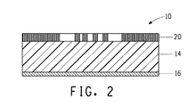
一実施形態において、図1および図2に示すとおり、レリーフ印刷用の印刷フォームを製造するのに用いられる前駆体10は、少なくとも1つの光重合性層14を含む感光性要素10である。たいていの実施形態において、レリーフ印刷用の複合印刷フォームに用いる1つ以上の印刷フォームを製造するのに用いる感光性要素10は、支持材16と、支持材に隣接した少なくとも1つの光重合性層14とを含む。光重合性層は、バインダー、少なくとも1つのモノマーおよび光開始剤を含むエラストマー層である。
In one embodiment, as shown in FIGS. 1 and 2, the
本発明の方法は、感光性要素10に隣接して支持材16と反対の光重合性層14の側面上に配置されるマスク20を提供することを含む。フロントマスク、前側マスクまたは画像マスクとも呼ばれることのあるマスク20は特に限定されず、画像を含む作品またはテンプレート、例えば、写真ネガまたはフォトツール(例えば、ハロゲン化銀フィルム)または光重合性層上に予め形成された画像領域を有する一体化マスクを挙げることができる。フォトツールの製造は、当業者には周知されている。図1および図2に示すとおり、たいていの実施形態において、感光性要素10は、光重合性層14(支持材16と反対)上に配置された化学線不透過層21を含む。化学線不透過層21は、デジタル情報に基づいてマスク20を形成することができ、一体化マスクまたはイン・サイチュマスクとも呼ばれる。ある実施形態において、化学線不透過層21はまた、赤外レーザー光によるデジタルマスク形成のための赤外線に対して感受性があってもよく、このように、化学線不透過とは、赤外線感受性層21とも呼ぶことができる。放射線不透過層および/または赤外線感受性層を備えた感光性要素10の他の実施形態も可能である。化学線不透過層は、感光性要素と一体化させる、または別の要素と関連させて、組み合わせて集合体を形成することができる。化学線不透過層(または一体化マスク)を有する未硬化感光性要素は、本明細書においては、デジタル感光性要素と呼ばれることもある。
The method of the present invention includes providing a
図4に示すとおり、フロントマスク20は、少なくとも画像領域22と非画像領域24とを含む。感光性要素10をより効率的に使用し、要素の取扱いを最小限にするために、2つ以上の画像領域22(それぞれが、最終的に、1つ以上の複合フォームの印刷フォームとなる)を互いに隣接配置して、前駆体のためのマスク20を形成する。たいていの実施形態において、マスク20は、2つ以上の画像領域22と2つ以上の非画像領域24とを含むであろう。たいていの実施形態において、非画像領域24は、各画像領域22を囲んでいて、画像領域周囲の空間の余地を提供し、1つの画像領域を隣接する画像領域から分離するであろう。マスクは、不透明領域と「透明」領域とを含む。マスクの不透明領域によって、光重合性材料下が、化学線に露光されるのが防がれ、暗い領域でカバーされた光重合性層のこれらの領域は重合しない。マスクの「透明」領域は、光重合性層を、化学線に露光して、重合または架橋する。マスク20の画像領域22は、不透明領域22aと透明領域22bを含み、それらは、印刷フォームによる印刷用のレリーフ構造を形成するのに好適な画像を一緒に提供するであろう。マスク20の非画像領域24は、不透明領域24aを含む。
As shown in FIG. 4, the
当業者に周知されているとおり、複合印刷フォームにより印刷されるテキストと画像を含む図形情報の設計は、コンピュータソフトウェアに捕捉および操作されて、ページレイアウトデータを含むデータファイルが作成される。ページレイアウトデータは、図形情報が「ページ」または基材に印刷されるであろう1つ以上の位置を表わすベクターまたはビットマップデータに基づくものとすることができる。ページレイアウトデータは、非画像領域により分離された画像領域を生成するために用いられて、かつ、画像形成デバイス、すなわち、レーザーイメージャーにより用いられて、感光性要素のマスクが形成される。ページレイアウトデータを用いて、1つ以上の複合印刷フォームに必要な印刷フォームの数およびサイズを決めることができる。ページレイアウトデータに基づいて、コンピュータはまた、典型的に、前駆体のための切断ガイドも生成する。 As is well known to those skilled in the art, the design of graphic information including text and images printed by a composite printing form is captured and manipulated by computer software to create a data file containing page layout data. The page layout data may be based on vector or bitmap data representing one or more locations where graphic information will be printed on a “page” or substrate. The page layout data is used to generate image areas separated by non-image areas and is used by an imaging device, ie, a laser imager, to form a mask of photosensitive elements. The page layout data can be used to determine the number and size of print forms required for one or more composite print forms. Based on the page layout data, the computer also typically generates a cutting guide for the precursor.
デジタル方法は、コンピュータから前駆体まで、生成されたテキストおよび画像を含む図形情報をデジタル(すなわち、コンピュータ制御)で移動する任意の方法に関する。ある実施形態において、デジタル方法には、感光層上に配置され、感光性要素と一体化された画像の形成が含まれ、不透明領域と透明領域の画像領域を有する一体化マスクとして機能する。デジタル方法はまた、コンピュータ・トゥ・プレート技術または方法とも呼ばれることもある。デジタル方法はまた、本明細書において、デジタル技術またはデジタル画像技術とも呼ばれる。 Digital methods relate to any method of digitally (ie, computer controlled) moving graphical information, including generated text and images, from a computer to a precursor. In certain embodiments, the digital method includes the formation of an image disposed on the photosensitive layer and integrated with the photosensitive element, and functions as an integrated mask having image areas of opaque and transparent areas. Digital methods may also be referred to as computer-to-plate technology or methods. Digital methods are also referred to herein as digital technology or digital image technology.
図1に示すとおり、前駆体10が、光重合性層14上に配置された赤外線感受性層21を含む一実施形態において、一体化マスク20は、赤外線感受性層からデジタルで形成される。前駆体に、マスクを通して、化学線に露光する処理において、一体化マスクは、まず、支持材と反対の光重合性層の表面に形成、またはその上に配置される。赤外線感受性層は、感光性要素の一体化マスクをそれ自体が形成する、または1つ以上の隣接(放射線不透過)層と組み合わせて用いて、要素に一体化マスクを形成することができる。光重合性層の像様露光に必要な画像は、任意のデジタル方法により生成することができる。
As shown in FIG. 1, in one embodiment where the
デジタル感光性要素は、ある実施形態において、(従来のフォトツールフィルム画像の代わりに)レーザー光を用いて、感光性要素の一体化マスクを形成するデジタル画像技術に用いられる化学線不透過層としても機能し得る赤外線感受性層を含む。デジタル方法は、レーザー光により、光重合性層に、またはその上に配置された一体化マスクを作製する。マスク画像を作製するデジタル方法は、像様露光前に、感光性要素を作製するのに1つ以上の工程を必要とする。概して、イン・サイチュのマスク形成のデジタル方法は、放射線不透過層の、支持材と反対の感光性要素の表面からの、または表面への選択的な除去か、移動のいずれかを行う。カーボンブラックやグラファイト等の暗色無機顔料、顔料、金属および金属合金の混合物のような黒い赤外線感受性層の材料の存在は、赤外線感受性材料と放射線不透過材料の両方として機能する。一体化マスクは、化学線に露光する後の工程のために、感光性要素に残る。 The digital photosensitive element, in one embodiment, as an actinic radiation opaque layer used in digital imaging technology that uses laser light (instead of a conventional phototool film image) to form an integral mask of the photosensitive element. Also includes an infrared sensitive layer that can function. The digital method creates an integrated mask placed on or on the photopolymerizable layer by laser light. Digital methods for producing mask images require one or more steps to produce a photosensitive element prior to imagewise exposure. In general, digital methods of in-situ mask formation either selectively remove or move the radiopaque layer from or to the surface of the photosensitive element opposite the support. The presence of black infrared sensitive layer materials, such as dark inorganic pigments such as carbon black and graphite, pigments, mixtures of metals and metal alloys, function as both infrared sensitive and radiopaque materials. The integrated mask remains on the photosensitive element for later processing with exposure to actinic radiation.
あるデジタル方法において、感光性要素は、最初、光重合性層の全表面をカバーする、または実質的にカバーする赤外線感受性層を含むであろう。赤外線感受性層を、赤外レーザー光に像様露光して、光重合性層、すなわち、一体化マスクに、またはその上に配置された画像を形成する。Fanによる(特許文献12)および(特許文献13)ならびにFanによる(特許文献14)に開示されているとおり、赤外レーザー光は、赤外線感受性層(すなわち、放射線不透過層)を、光重合性層から、選択的に除去、例えば、切除または蒸発させることができる。Van Zoerenによる(特許文献15)に開示されているとおり、赤外線感受性層に隣接する材料捕捉シートが、感光性要素から除去される際に材料を捕捉するために、レーザー露光中存在していてもよい。感光性要素から除去されなかった赤外線感受性層の一部のみが、放射線不透過層の一体化マスクを形成する要素に残るであろう。 In some digital methods, the photosensitive element will initially include an infrared sensitive layer that covers or substantially covers the entire surface of the photopolymerizable layer. The infrared sensitive layer is imagewise exposed to infrared laser light to form an image disposed on or on the photopolymerizable layer, ie, the integrated mask. As disclosed in Fan (Patent Document 12) and (Patent Document 13) and Fan (Patent Document 14), an infrared laser beam causes an infrared sensitive layer (ie, a radiopaque layer) to be photopolymerized. The layer can be selectively removed, for example, excised or evaporated. As disclosed in Van Zoeren (US Pat. No. 6,057,049), a material capture sheet adjacent to the infrared sensitive layer may be present during laser exposure to capture material as it is removed from the photosensitive element. Good. Only a portion of the infrared sensitive layer that has not been removed from the photosensitive element will remain in the element forming the integral mask of the radiopaque layer.
マスク形成の他のデジタル方法において、感光性要素は、最初、赤外線感受性層を含んでいない。放射線不透過層として赤外線感受性層を含む別の要素は、典型的に、光重合性層である、支持材と反対の感光性要素の表面に放射線不透過層が隣接するように、感光性要素により集合体を形成するであろう。(存在する場合、光重合性層と関連したカバーシートは、集合体の形成前に除去してもよい。)別の要素は、デジタル露光プロセスを促進するために、放出層または加熱層等の1つ以上の他の層を含んでいてもよい。これらのその他の層も赤外線感受性層と考えることができる。ここで、放射線不透過層はまた、赤外線にも感受性がある。Fanらによる(特許文献16)ならびにBlanchettによる(特許文献17)、(特許文献18)および(特許文献19)に開示されているとおり、集合体は、赤外レーザー光で像様露光されて、放射線不透過層を選択的に移動し、光重合性層に、またはその上に配置された画像を形成する。移動した放射線不透過層の一部のみが、一体化マスクを形成する感光性要素に存在するであろう。 In other digital methods of mask formation, the photosensitive element initially does not include an infrared sensitive layer. Another element comprising an infrared sensitive layer as a radiopaque layer is typically a photopolymerizable layer, such that the radiopaque layer is adjacent to the surface of the photosensitive element opposite the support. Will form an aggregate. (If present, the cover sheet associated with the photopolymerizable layer may be removed prior to formation of the assembly.) Another element may be a release layer or heating layer, etc. to facilitate the digital exposure process. One or more other layers may be included. These other layers can also be considered infrared sensitive layers. Here, the radiopaque layer is also sensitive to infrared radiation. As disclosed by Fan et al. (Patent Document 16) and by Blanchett (Patent Document 17), (Patent Document 18) and (Patent Document 19), the aggregate is imagewise exposed with infrared laser light, The radiopaque layer is selectively moved to form an image disposed in or on the photopolymerizable layer. Only a portion of the transferred radiopaque layer will be present in the photosensitive element forming the integral mask.
一体化マスクは、別のキャリアで作製されてから、熱および/または圧力を、支持材と反対の光重合性層の表面に加えることにより移動してもよいものとも考えられる。光重合性層は、典型的に、粘着性で、転写画像を保持するであろう。任意で、別のキャリアを、像様露光前に、要素から除去することができる。別のキャリアは、赤外レーザー光に像様露光されると、放射線不透過材料を選択的に除去して、画像を形成する放射線不透過層である、または放射線不透過層と関連した赤外線感受性層を有していてもよい。このタイプの別のキャリアの一例は、Rexam,Inc.製LaserMask(登録商標)画像形成フィルムである。あるいは、放射線不透過材料の画像は、別のキャリアへ、レーザー光により、放射線不透過材料を有する他の要素から転写されてもよい。 It is also contemplated that the integrated mask may be made with another carrier and then moved by applying heat and / or pressure to the surface of the photopolymerizable layer opposite the support. The photopolymerizable layer is typically tacky and will retain the transferred image. Optionally, another carrier can be removed from the element prior to imagewise exposure. Another carrier is a radiopaque layer that selectively removes the radiopaque material upon imagewise exposure to infrared laser light to form an image, or infrared sensitivity associated with the radiopaque layer. It may have a layer. An example of another carrier of this type is Rexam, Inc. LaserMask (registered trademark) image forming film. Alternatively, an image of the radiopaque material may be transferred from another element having the radiopaque material by laser light to another carrier.
赤外レーザー光による像様露光は、750〜20,000nmの範囲で放出する様々なタイプの赤外レーザーを用いて実施することができる。780〜2,000nmの範囲のダイオードレーザーを含む赤外レーザーおよび1064nmで放出するNd:YAGレーザーが好ましい。化学放射線不透過層を、感光性要素から像様除去する赤外レーザー露光の好ましい装置および方法は、Fanらによる(特許文献20)および(特許文献21)に開示されている。一体化マスクは、化学線への全体露光の後の工程のために感光性要素に残る。感光性要素の表面にイン・サイチュのマスクをデジタル形成するのに用いるある好適な赤外レーザー露光装置は、CYREL(登録商標)Digital Imager(Gent,BelgiumのEskoArtworkにより販売)である。 Imagewise exposure with infrared laser light can be carried out using various types of infrared lasers emitting in the range of 750 to 20,000 nm. Infrared lasers including diode lasers in the range of 780 to 2,000 nm and Nd: YAG lasers emitting at 1064 nm are preferred. A preferred apparatus and method for infrared laser exposure for imagewise removal of the actinic radiation opaque layer from the photosensitive element is disclosed in Fan et al. (Patent Document 20) and (Patent Document 21). The integrated mask remains on the photosensitive element for subsequent processing after the total exposure to actinic radiation. One suitable infrared laser exposure apparatus used to digitally form an in-situ mask on the surface of the photosensitive element is the CYREL® Digital Imager (sold by EskoArtwork, Gent, Belgium).
本発明の方法は、化学線不透過シートから背面マスク30を形成することを含む。図3に示すとおり、背面マスク30は、カットアウト領域32と無傷領域34とを有する。たいていの実施形態において、背面マスク30は、2つ以上のカットアウト領域32と2つ以上の無傷領域34とを含むであろう。シートとして選択した材料が、化学線がシート(無傷領域で)を通して透過するのを防ぎ、切断して、1つ以上のカットアウト領域を形成できるのであれば、化学線不透過シートは特に限定されない。化学線不透過シートは、化学線不透過シートが2.3%以下の透過率を有するとき、化学線が(無傷領域)を通して、感光性要素へ透過するのを十分に防ぐことができる。場合によっては、この透過率は、約1.6を超える光学密度を有する化学線不透過シートに対応する。一実施形態において、化学線不透過シートの透過率は、1.6%以下である。背面マスクを形成するのに好適な材料としては、これらに限られるものではないが、金色のロッドおよびオレンジ色のプラスチックシートが挙げられる。背面マスク30の1つ以上のカットアウト領域32は、手で、またはコンピュータ駆動切断デバイスにより切断することができる。たいていの実施形態において、背面マスクを形成する材料は、コンピュータに接続された自動切断テーブルに配置され、カットアウト領域は、ページレイアウトデータに基づいて、好適なサイズおよび形状へと切断される。背面マスク30の1つ以上のカットアウト領域32のそれぞれのサイズおよび形状は、光重合性層上に配置されたマスク20、すなわち、前側マスク20の1つ以上の対応画像領域22のそれぞれのサイズおよび形状と同じ、または実質的に同じである。特に好適な切断テーブルは、EskoArtwork製のKongsbergデジタル変換テーブルである。典型的に、背面マスクの1つ以上のカットアウト領域が除去された時点で、1つ以上の無傷領域はまだ接続されており、背面マスクは単一シートとして残る。
The method of the present invention includes forming a
図4に示すとおり、本発明の方法は、画像マスク20および背面マスク30を備えた感光性要素10を組み立てることを含む。組立工程は、感光性要素10の支持材16に隣接して、背面マスク30を配置し、背面マスク30を、感光性要素と関連したマスク20と並べることを含む。一実施形態において、組立工程は、背面マスク30に隣接して、一体化マスク20を有する感光性要素10を配置し、背面マスク30の無傷領域34を、一体化マスク20の非画像領域24と並べることを含む。他の実施形態において、組立は、支持材と反対の感光性要素の側部に隣接して、フォトツールを配置し、感光性要素の支持材側に隣接して、背面マスクを配置し、背面マスクの無傷領域を、前側マスクと背面マスクとの間に感光性要素を備えたフォトツールの非画像領域と並べることを含む。背面マスク30の無傷領域34を、前側マスク20の対応する非画像領域24と並べるとまた、同時に、背面マスク30のカットアウト領域32が、前側マスク20の画像領域22と並ぶ。ある実施形態において、感光性要素および背面マスクは、実質的に同じサイズ、すなわち、同じ、または実質的に同じ長さおよび幅寸法を有するため、背面マスクの無傷領域および前側マスクの非画像領域は、背面マスクの対応する寸法に隣接して、感光性要素の適切な寸法を単に配置することにより適切に並ぶであろう。他の実施形態において、背面マスクおよび感光性要素(およびフォトツール)は、それぞれ、1つの端部に沿って1つ以上の穴を穿孔し、ピンバーに装着して、背面マスクと、感光性要素の前側マスクと適切に確実に並べることができる。さらに他の実施形態において、背面マスクおよび一体化マスクは、それぞれ、ターゲットまたは交差線等の1つ以上の位置合わせマーキングを、ページレイアウトデータにより決まる適切な位置で含むことができ、位置合わせマーキングを用いて、背面マスクの無傷領域と、前側マスクの非画像領域を並べる。位置合わせマーキングは、並べることのできるマスクに作製できる任意の種類の視覚インジケータを含むことができる。
As shown in FIG. 4, the method of the present invention includes assembling a
背面マスク30および前側マスク20を有する感光性要素10は、感光性要素を放射線に露光する次の工程での作製において、感光性要素を化学線に露光するデバイスで組み立てる。本発明は限定されないが、たいていの実施形態において、露光デバイスは、平床露光デバイスであり、組み立てた感光性要素および背面マスクは、化学線の1つ以上の源に隣接する平らな水平透明表面にある。
The
図5Aに示すとおり、本発明の方法は、感光性要素10を、化学線36に、前側マスク20を通して露光し、感光性要素を、化学線38に、背面マスク30を通して露光する工程を含む。感光性要素10を、化学線に、前側マスク20および背面マスク30を通して露光すると、光重合性層が、前側および背面から選択的に露光される。感光性要素10を、化学線36に、前側20マスクを通して露光するのは、任意の順番で連続して行う、または、感光性要素を、化学線38に、背面マスク30を通して露光するのと同時に行うことができる。マスクの不透過領域は、下にある光重合性材料が、化学線に露光されるのを防ぐため、暗い、または不透過領域によりカバーされた光重合性層のこれらの領域は重合しない。マスクの「透明」領域によって、化学線で光重合性層を露光して、重合または架橋または硬化することができる。
As shown in FIG. 5A, the method of the present invention includes exposing the
図4、図5Aおよび図5Bに示すとおり、前側マスク20の画像領域22は、不透明領域22aおよび透明領域22bを含み、前側マスクを通した露光後、画像領域22に対応する光重合性層14に硬化部分42と未露光部分44を形成するであろう。画像領域22に対応する光重合性層の未露光部分44を除去する処理後、硬化部分42は残って、印刷フォームによる印刷に好適なレリーフ表面であるレリーフ領域50を形成する。前側マスク20の非画像領域24は、不透明領域24aのみを含み、前側マスクを通した露光後、下にある光重合性層14を硬化または重合しないであろう。露光後、前側マスク20の非画像領域24に対応する光重合性層は、層14の未露光領域54である。
As shown in FIGS. 4, 5A and 5B, the
背面マスク30のカットアウト領域32は、実質的に透明領域であり、感光性要素の化学線への背面マスクのカットアウト領域を通した露光により、光重合性層が硬化する。化学線38への背面マスク20を通した露光は、レリーフ領域50の硬化部分42に隣接する硬化光ポリマーのフロア48を形成するのに十分なものである。背面マスク30の無傷領域34は、十分に低い透過率を有しており、実質的に不透明領域であり、無傷領域に隣接する光重合性層14の重合または硬化を防いで、非画像領域24に対応する光重合性層14の未露光領域54は未硬化または架橋しないままとなる。化学線への前側および背面露光後、前側マスク20の非画像領域24に隣接し、背面マスク30の無傷領域24に隣接する光重合性層14は、感光性要素の未露光領域54である。化学線への前側および背面露光後、前側マスク20の画像領域22に隣接し、背面マスク30のカットアウト領域32に隣接する光重合性層は、硬化ポリマー材料のフロア48に隣接する硬化部分42と未硬化部分44の両方を有する光重合性層14の画像部分である。
The cut-out
感光性要素10は、前側マスク20の画像領域22と背面マスク30のカットアウト領域32を通して、好適な源から化学線に露光される。化学線露光時間は、放射線の強度およびスペクトルエネルギー分布、感光性要素からのその距離、必要な画像解像度および光重合性組成物の性質および量に応じて、数秒から数分まで変えることができる。露光温度は、好ましくは、周囲かそれよりやや高い、すなわち、約20℃〜約35℃である。前側マスクの画像領域を通した露光は、露光領域を、背面露光層、すなわち、フロアまで架橋するのに十分な間とする。像様露光時間、すなわち、前側マスクの画像領域を通した露光は、典型的に、背面露光時間、すなわち、背面マスクのカットアウト領域を通した露光時間より長く、数分から数十分に及ぶ。
The
化学線源は、紫外および可視波長領域を含む。特定の化学線源の好適性は、開始剤の感光性および感光性要素を製造するのに用いる少なくとも1つのモノマーに左右される。レリーフ印刷用の最も一般的な感光性要素の好ましい感光性は、それらは、良好な室内光安定性を与えるため、スペクトルのUVおよび深UV領域にある。好適な可視およびUV源としては、カーボンアーク、水銀蒸気アーク、蛍光ランプ、電子フラッシュユニット、電子ビームユニット、レーザーおよび写真フラッドランプが例示される。UV線の最も好適な源は、水銀蒸気ランプ、特に、太陽ランプである。業界標準の放射線源としては、Sylvania350 Blacklight蛍光ランプ(FR48T12/350VL/VHO/180,115w)およびPhilips UV-A「TL」−シリーズ低圧水銀蒸気蛍光ランプが例示される。典型的に、水銀蒸気アークまたは太陽ランプは、感光性要素から約1.5〜約60インチ(約3.8〜約153cm)の距離で用いることができる。これらの放射線源は、概して、310〜400nmの長波UV放射線を放出する。これらの特定のUV源に感受性のあるフレキソ印刷版は、310〜400nm吸収する光開始剤を用いる。 Actinic radiation sources include the ultraviolet and visible wavelength regions. The suitability of a particular source of actinic radiation depends on the photosensitivity of the initiator and at least one monomer used to produce the photosensitive element. The preferred photosensitivity of the most common photosensitive elements for relief printing is in the UV and deep UV regions of the spectrum to give good room light stability. Suitable visible and UV sources include carbon arcs, mercury vapor arcs, fluorescent lamps, electronic flash units, electron beam units, lasers and photographic flood lamps. The most preferred source of UV radiation is a mercury vapor lamp, in particular a solar lamp. Industry standard radiation sources include Sylvania 350 Blacklight fluorescent lamps (FR48T12 / 350VL / VHO / 180, 115w) and Philips UV-A “TL” -series low pressure mercury vapor fluorescent lamps. Typically, a mercury vapor arc or solar lamp can be used at a distance of about 1.5 to about 60 inches (about 3.8 to about 153 cm) from the photosensitive element. These radiation sources generally emit 310-400 nm long wave UV radiation. Flexographic printing plates sensitive to these specific UV sources use photoinitiators that absorb 310-400 nm.
マスクがフォトツールのときは、真空下での像様露光が典型的に用いられる。一体マスクを有する感光性要素の化学線への像様露光は限定されず、大気酸素の存在下、または大気酸素を存在させずに、または不活性ガスと大気より少ない酸素濃度の環境中で実施してよい。大気酸素は、露光が真空中で行われるときは排除される。露光を真空中で行って、その層で生じる重合反応への酸素の影響を最小にしてもよい。マスクは、イン・サイチュで形成される、または光重合性層の放射性不透過材料により像様適用され、一体マスクとの密着を確実にするのに真空を必要としないため、露光は、大気酸素存在下で行ってよい。印刷フォームを製造する方法のある実施形態において、真空なし、すなわち、感光性要素は、大気酸素の存在下にあって、一体マスクの上部に存在する追加の層なしで、露光工程は実施される。印刷フォームを製造する方法の他の実施形態において、露光工程は、不活性ガスと190,000ppm〜100ppmの酸素濃度の環境で実施される。好適な不活性ガスとしては、これらに限られるものではないが、アルゴン、ヘリウム、ネオン、クリプトン、キセノン、窒素、二酸化炭素およびこれらの組み合わせが挙げられる。不活性ガスと、190,000ppm〜100ppmの範囲の制御された酸素濃度の環境におけるデジタル感光性要素の露光の好適な方法は、(特許文献22)、(特許文献23)および(特許文献24)に記載されている。 When the mask is a phototool, imagewise exposure under vacuum is typically used. Imagewise exposure of a photosensitive element having an integral mask to actinic radiation is not limited and can be performed in the presence of atmospheric oxygen, in the absence of atmospheric oxygen, or in an inert gas and oxygen-less atmosphere. You can do it. Atmospheric oxygen is excluded when exposure is performed in a vacuum. Exposure may be performed in vacuum to minimize the effect of oxygen on the polymerization reaction that occurs in that layer. Since the mask is formed in situ or imagewise applied with a radiopaque material in the photopolymerizable layer and does not require a vacuum to ensure intimate contact with the integral mask, exposure is performed with atmospheric oxygen You can do it in the presence. In certain embodiments of the method of manufacturing the printing form, the exposure step is performed without a vacuum, i.e., the photosensitive element is in the presence of atmospheric oxygen and without an additional layer present on top of the integral mask. . In another embodiment of the method for producing a printing form, the exposure step is performed in an environment of inert gas and oxygen concentration of 190,000 ppm to 100 ppm. Suitable inert gases include, but are not limited to, argon, helium, neon, krypton, xenon, nitrogen, carbon dioxide and combinations thereof. Suitable methods for exposure of digital photosensitive elements in an environment of inert gas and controlled oxygen concentration in the range of 190,000 ppm to 100 ppm include (Patent Document 22), (Patent Document 23) and (Patent Document 24). It is described in.
感光性要素10を、化学線38に、背面マスク30を通して露光する工程によって、光重合性層14が背面マスクのカットアウト領域32を通して露光され、画像領域22に対応する硬化部分42に隣接する硬化ポリマー材料のフロア48が形成される。背面露光を用いて、重合材料の層、すなわち、フロアを、光重合性層14の支持材16に形成し、光重合性層を感光性とすることができる。フロア48は、光重合性層と支持材との間に改善された接着力を与え、レリーフの深さを定める。背面マスク30を用いて、背面マスク30のカットアウト領域32に対応する、支持材16に隣接する光重合性層14の1つ以上の部分を選択的に露光する。化学線への背面露光中、背面マスク30の無傷領域34の存在によって、無傷領域に隣接する光重合性材料が、露光されるのを防ぎ、無傷領域によってカバーされる光重合層の領域は、フロアを形成しない、あるいは重合または硬化しない。無傷領域34を有する背面マスク30を通した露光は、感光性要素に、前側マスク20の非画像領域24に対応する光重合性層14の未露光領域54を提供する。バックフラッシュ露光38は、他の画像形成工程前、後または中に行うことができる。全体(像様)化学線露光工程について上述した従来の放射線源のいずれかを、バックフラッシュ露光工程に用いることができる。露光時間は、概して、数秒から数分に及ぶ。たいていの実施形態において、フロアの厚さは、光重合性層の全厚の約半分であるが、限定されない。
The process of exposing the
本発明の方法は、固体光重合性層を有する感光性要素からレリーフ印刷フォームを製造する従来の方法とは、従来の方法には、画像領域および非画像領域の支持材に隣接する光ポリマーの硬化層、すなわち、フロアを形成するのに、化学線への非選択性バックフラッシュ露光、すなわち、マスクなしの全体またはブランケット露光が含まれるという点で異なる。本発明の方法には、背面マスクの存在が含まれ、これによって、支持材を通した光重合性層の選択的バックフラッシュ、および感光性要素のポリマー材料のフロアの選択的形成が可能となる。背面露光によって、光重合性層と支持材との間の接着が改善でき、背面マスクは、支持材の光重合性層を選択的に露光するため、光重合性層の支持材への接着は、レリーフ領域50および未露光領域54との間とは異なり、後の工程において、未露光領域54の除去が促される。
The method of the present invention differs from the conventional method of producing a relief printing form from a photosensitive element having a solid photopolymerizable layer in that the conventional method involves the photopolymer adjacent to the image and non-image region supports. The formation of the hardened layer, i.e. the floor, is different in that it comprises a non-selective backflash exposure to actinic radiation, i. The method of the present invention includes the presence of a back mask, which allows the selective backflushing of the photopolymerizable layer through the support and the selective formation of the polymeric material floor of the photosensitive element. . The back exposure can improve the adhesion between the photopolymerizable layer and the support material, and the back mask selectively exposes the photopolymerizable layer of the support material, so the adhesion of the photopolymerizable layer to the support material is Unlike between the
前側マスク20と背面マスク30の両方を通したUV線への露光後、本発明の方法には、感光性要素10を処理して、前側マスク20の1つ以上の画像領域22に対応する要素の1つ以上の領域において印刷するのに好適なレリーフ表面を形成することが含まれる。図6に示すとおり、処理工程で、光重合性層の化学線に露光されなかった領域、すなわち、未露光領域または未硬化領域の光重合性材料の一部または全てが除去される。前側および背面露光後に要素を処理すると、光重合性層14の対応の画像領域22において、未硬化、すなわち、未露光領域44が除去される。処理によって、画像領域22に対応する光重合性層14の未露光部分44が除去されて、画像領域22に対応するフロア48を備えた硬化部分42のレリーフ領域50が形成される。処理によってまた、背面マスク30の無傷領域34および前側マスク20の非画像領域24に対応する未露光部分54で、光重合性層14の一部も除去することができる。本発明の方法によって、感光性要素10の非画像領域24における支持材16の全てにわたって、光重合性材料14の層を完全に除去するための処理工程の必要性が排除され、処理装置およびプロセスに対する影響が最小化され、かつ、印刷フォームのレリーフ領域に対する損傷が最小または排除される。たいていの実施形態において、処理によって、前側マスクの画像領域22に対応する光重合性層14における未重合部分44が除去されて、レリーフ領域50が形成され、未露光領域54を形成するため、前側マスクの非画像領域24に対応する未露光光重合性材料の一部が除去されるであろう。エラストマーキャッピング層を除き、典型的に、光重合性層またはその上に存在してよい追加の層は、光重合性層の重合領域から除去または実質的に除去される。一体マスク画像を有する感光性要素については、処理工程によってまた、マスク画像(化学線に露光された)も除去される。
After exposure to UV radiation through both the
たいていの実施形態において、フロア48の厚さは、光重合性層14の全厚の約半分である。処理後のある実施形態において、非画像領域24に対応する支持材16上に残る光重合性層14の未露光領域54の厚さは、画像領域22に形成されたフロア48の厚さと同じ、または実質的に同じである。処理後の他の実施形態において、非画像領域24に対応する支持材16上に残る光重合性層14の未露光領域54の厚さは、レリーフ領域50のフロア48の厚さより薄い。処理後、非画像領域24は、約40ミル(0.10cm)〜フロア48の厚さと略同じ厚さを有する。処理後の他の実施形態において、非画像領域24は、約50ミル(0.13cm)〜フロア48の厚さと略同じ厚さとすることのできる厚さを有する。処理後のさらに他の実施形態において、非画像領域24は、略フロアの厚さ〜フロア厚さより約20ミル(0.051cm)薄い範囲とすることのできる厚さを有する。すなわち、非画像領域24の厚さは、フロア厚さより約1〜約20ミル(0.0025cm〜0.051cm)薄い厚さとすることができる。処理後のさらに他の実施形態において、非画像領域24は、略フロアの厚さ〜フロアの厚さより約10ミル(0.03cm)薄い範囲とすることのできる厚さを有する。すなわち、非画像領域24の厚さは、フロア厚さより約1〜約10ミル(0.0025cm〜0.025cm)薄い厚さとすることができる。この方法は、約90〜280ミル(0.23〜0.71cm)の厚さを有する光重合性層を備えた感光性要素に特に好適である。例えば、約102ミル(0.26cm)の厚さを有する光重合性層を有する感光性要素の処理後、フロアは、約51ミル(0.129cm)の厚さを有することができ、非画像領域に対応する光重合性層の残りの未露光領域は、約30〜約51ミル(0.08〜0.129cm)とすることのできる厚さを有する。他の例として、厚さ245ミル(0.62cm)の光重合性層を有する感光性要素の処理後、フロアは、約123ミル(0.31cm)の厚さを有することができ、非画像領域に対応する光重合性層の残りの未露光領域は、約50〜約123ミル(0.13〜0.31cm)とすることのできる厚さを有する。
In most embodiments, the thickness of the
感光印刷要素の処理には、(1)光重合性層が、好適な現像溶液と接触して、画像領域の未重合領域を洗浄する「湿式」現像と、(2)感光性要素が現像温度まで加熱されて、光重合性層の画像領域の未重合領域が、溶融または軟化または流動して、吸収材料との接触により水分が除去される「乾式」現像が含まれる。乾式現像はまた、熱現像とも呼ばれることがある。たいていの実施形態において、処理によって、画像部分の硬化ポリマー材料のフロアまで、未硬化部分が全て、または実質的に全て除去される。また、処理によって、未硬化部分が、画像部分のフロアまで除去されるとき、処理によって、要素の未露光部分の未硬化光ポリマー材料の一部が、硬化フロアの略厚さかそれより僅かにそれに満たない厚さまで除去される。露光感光性要素を処理して、画像部分の未硬化材料を、硬化ポリマー材料のフロアまで完全に除去されないようにすることが可能である。この実施形態においては、要素の未露光部分における未硬化光ポリマー材料の一部を除去する処理は、それに応じて調整されるであろう。 Processing of the photosensitive printing element includes (1) “wet” development in which the photopolymerizable layer is in contact with a suitable developer solution to clean the unpolymerized areas of the image area; and (2) the photosensitive element is at the development temperature. "Dry" development in which the unpolymerized areas of the image areas of the photopolymerizable layer are melted or softened or flowed to remove moisture by contact with the absorbent material. Dry development may also be referred to as thermal development. In most embodiments, the process removes all or substantially all of the uncured portion down to the cured polymer material floor of the image portion. Also, when the process removes the uncured portion down to the floor of the image portion, the process causes a portion of the uncured photopolymer material in the unexposed portion of the element to be approximately the thickness of the cured floor or slightly less than that. Removed to a thickness less than The exposed photosensitive element can be processed so that the uncured material of the image portion is not completely removed to the floor of the cured polymer material. In this embodiment, the process of removing a portion of the uncured photopolymer material in the unexposed portions of the element will be adjusted accordingly.
湿式現像は、通常、略室温で行われる。現像剤は、有機溶媒、水性または半水性溶液および水とすることができる。現像剤の選択は、主に、除去する光重合性材料の化学的性質に応じて異なるであろう。好適な有機溶媒現像剤としては、芳香族または脂肪族炭化水素および脂肪族または芳香族ハロ炭化水素溶媒、またはかかる溶媒と好適なアルコールの混合物が挙げられる。その他の有機溶媒現像剤は、(特許文献25)に開示されている。好適な半水性現像剤は、通常、水と水混和性有機溶媒とアルカリ材料を含有している。好適な水性現像剤は、通常、水とアルカリ材料を含有している。その他の好適な水性現像剤の組み合わせは、(特許文献26)に記載されている。 Wet development is usually performed at about room temperature. The developer can be an organic solvent, an aqueous or semi-aqueous solution and water. The choice of developer will depend primarily on the chemistry of the photopolymerizable material being removed. Suitable organic solvent developers include aromatic or aliphatic hydrocarbons and aliphatic or aromatic halohydrocarbon solvents, or mixtures of such solvents with suitable alcohols. Other organic solvent developers are disclosed in (Patent Document 25). Suitable semi-aqueous developers usually contain water, a water miscible organic solvent and an alkaline material. Suitable aqueous developers usually contain water and an alkaline material. Other suitable aqueous developer combinations are described in US Pat.
現像時間は変えることができるが、好ましくは、約2〜約25分の範囲である。現像剤は、浸漬、スプレーおよびブラシまたはロール適用をはじめとする任意の都合のよいやり方で適用することができる。ブラシ助剤を用いて、画像領域の要素の未露光部分を除去することができる。洗浄は、現像剤および機械ブラシ動作を用いて、版の未重合部分を除去する自動処理ユニットで実施することができ、画像領域の露光画像およびフロア、非画像領域に対応する未露光領域の光重合性層のある部分を構成するレリーフが残る。たいていの実施形態において、プロセッサは、フロアに対する画像領域の未露光光ポリマーを除去するのに十分なブラシ動作を行う、または、ブラシ動作によって、非画像領域に対応する未露光領域の未硬化光ポリマー層の大半を除去できないため、ブラシの深さでの停止を含むことができる。 Development time can vary, but it is preferably in the range of about 2 to about 25 minutes. Developer can be applied in any convenient manner, including dipping, spraying and brush or roll application. Brush aids can be used to remove unexposed portions of the image area elements. Cleaning can be performed with an automatic processing unit that removes the unpolymerized portion of the plate using developer and mechanical brush action, and exposes the exposed image in the image area and the light in the unexposed area corresponding to the non-image area. The relief that constitutes a portion of the polymerizable layer remains. In most embodiments, the processor performs sufficient brushing to remove unexposed photopolymer in the image area relative to the floor, or by brushing, uncured photopolymer in the unexposed area corresponding to the non-image area. Since most of the layer cannot be removed, a stop at the brush depth can be included.
溶液中での現像による処理後、レリーフ印刷版は、概して、吸い取る、または拭き取って乾燥され、強制空気または赤外オーブンでより完全に乾燥される。乾燥時間および温度は、変えることができるが、典型的に、版は、60〜120分間、60℃で乾燥される。支持材が収縮する可能性があり、これによって位置合わせの問題が生じる恐れがあるため、高温は勧められない。 After processing by development in solution, the relief printing plate is generally blotted or wiped dry and dried more thoroughly in forced air or infrared ovens. The drying time and temperature can vary, but typically the plate is dried at 60 ° C. for 60-120 minutes. High temperatures are not recommended because the support can shrink and this can cause alignment problems.
要素の処理には、少なくとも1つの光重合性層(および追加の層)を有する感光性要素を、光重合性層の未硬化部分を軟化または溶融または流動させるのに十分な温度まで加熱して、要素の最外表面を、吸収剤表面と接触させて、溶融または流動部分を吸収または水分を取り去ることが含まれる。光重合性層の重合領域は、未重合領域より高い融点を有するため、熱現像温度で溶融、軟化または流動しない。フレキソ印刷版を形成するための感光性要素の熱現像は、Martensによる(特許文献27)、(特許文献28)、(特許文献29)およびWangらによる(特許文献30)に記載されている。 For processing the element, the photosensitive element having at least one photopolymerizable layer (and additional layers) is heated to a temperature sufficient to soften or melt or flow the uncured portion of the photopolymerizable layer. , Contacting the outermost surface of the element with the absorbent surface to absorb the molten or fluidized portion or remove moisture. Since the polymerized region of the photopolymerizable layer has a higher melting point than the unpolymerized region, it does not melt, soften or flow at the heat development temperature. Thermal development of photosensitive elements to form flexographic printing plates is described by Martens (Patent Document 27), (Patent Document 28), (Patent Document 29), and Wang et al. (Patent Document 30).
「溶融」という用語は、軟化して、粘度を減じて、吸収材料による流動および吸収を可能とさせる高温に晒される光重合性エラストマー層の未照射部分の挙動を説明するのに用いられる。光重合性層の溶融可能部分の材料は、通常、固体と液体間で鋭敏な転移のない粘弾性材料であり、プロセスは吸収材料の吸収のある閾値より高い任意の温度で加熱組成物層を吸収しない機能を果たす。広い温度範囲を利用して、本発明のために、組成物層を「溶融」することができる。吸収は、プロセスがうまく操作されている間、低温では遅く、高温では早くなる。 The term “melt” is used to describe the behavior of unirradiated portions of a photopolymerizable elastomer layer that is exposed to high temperatures that soften and reduce viscosity to allow flow and absorption by the absorbent material. The material of the meltable part of the photopolymerizable layer is usually a viscoelastic material without a sharp transition between solid and liquid, and the process involves heating the composition layer at any temperature above the absorption threshold of the absorbent material. Performs functions that do not absorb. A wide temperature range can be utilized to “melt” the composition layer for the purposes of the present invention. Absorption is slow at low temperatures and fast at high temperatures while the process is operating well.
感光性要素の加熱および要素の最外表面と吸収材料の接触の熱処理工程は、吸収材料との接触時に光重合性層の未硬化部分がまだ軟性または溶融状態にあれば、同時に、または、連続して行うことができる。少なくとも1つの光重合性層(および追加の層)は、伝導、対流、放射またはその他加熱方法により、未硬化部分を溶融させるには十分であるが、層の硬化部分を変形させるほどには高くない温度まで加熱される。光重合性層の上に配置された1つ以上の追加の層は、軟化または溶融または流動して、吸収材料により吸収されてもよい。感光性要素は、光重合性層の未硬化部分を溶融または流動するために、約40℃より高い、好ましくは、約40℃〜約230℃(104〜446°F)の表面温度まで加熱される。吸収材料と、未硬化領域において溶融する光重合性層との密着を多少なりとも維持することによって、未硬化感光材料の光重合性層から吸収材料への移動がなされる。尚加熱条件にある間、吸収材料は、支持材層と接触している硬化光重合性層から分離されて、レリーフ構造が現れる。光重合性層の加熱および溶融(部分)層の吸収材料との接触工程のサイクルは、未硬化材料を適切に除去し、十分なレリーフ深さを形成するのに必要なだけ何回も繰り返すことができる。しかしながら、好適なシステム性能のためにはサイクル数は最小とするのが望ましく、典型的には、光重合性要素は、5〜15サイクル熱処理される。吸収材料と光重合性層の密着(未硬化部分が溶融のまま)は、層と吸収材料を一緒にプレスすることによって維持することができる。感光性要素を熱現像する装置の実施形態は、Petersonらによる(特許文献31)、同じく、Johnsonらによる(特許文献32)に開示されている。感光性要素は、熱処理を行うために、ドラムまたは平面に配置することができる。 The heat treatment process of heating the photosensitive element and contacting the outermost surface of the element with the absorbent material may be simultaneous or continuous if the uncured portion of the photopolymerizable layer is still in a soft or molten state upon contact with the absorbent material. Can be done. At least one photopolymerizable layer (and additional layers) is sufficient to melt the uncured portion by conduction, convection, radiation or other heating methods, but high enough to deform the cured portion of the layer. Heated to no temperature. One or more additional layers disposed on the photopolymerizable layer may soften or melt or flow and be absorbed by the absorbent material. The photosensitive element is heated to a surface temperature of greater than about 40 ° C, preferably from about 40 ° C to about 230 ° C (104-446 ° F) to melt or flow the uncured portion of the photopolymerizable layer. The By maintaining some degree of adhesion between the absorbent material and the photopolymerizable layer that melts in the uncured region, the uncured photosensitive material moves from the photopolymerizable layer to the absorbent material. During the heating condition, the absorbing material is separated from the cured photopolymerizable layer in contact with the support material layer, and a relief structure appears. The cycle of heating the photopolymerizable layer and contacting the molten (partial) layer with the absorbent material should be repeated as many times as necessary to properly remove the uncured material and form a sufficient relief depth. Can do. However, it is desirable to minimize the number of cycles for suitable system performance, and typically the photopolymerizable element is heat treated for 5 to 15 cycles. Adhesion between the absorbent material and the photopolymerizable layer (the uncured portion remains molten) can be maintained by pressing the layer and the absorbent material together. An embodiment of an apparatus for thermally developing a photosensitive element is disclosed by Peter et al. (Patent Document 31) and also by Johnson et al. (Patent Document 32). The photosensitive element can be placed on a drum or flat surface for heat treatment.
吸収材料は、光重合性層の未硬化部分の融点を超える融点を有し、同じ操作温度で良好な引き裂き抵抗を有するものを選択する。選択した材料は、加熱中、感光性要素を処理するのに必要な温度に耐えるのが好ましい。吸収材料は、不織材料、紙料、繊維状織材料、開放気泡発泡材料、ボイド容積として多少なりともかなりの割合の内包容積を含む多孔性材料から選択される。吸収材料は、ウェブまたはシート形態とすることができる。吸収材料は、溶融エラストマー組成物の高吸収性も有していなければならない。好ましいのは、不織ナイロンウェブである。感光性要素は、1つ以上の処理工程を行って、未硬化部分を十分に除去して、レリーフを形成することができるものと考えられる。感光性要素は、湿式現像と乾式現像の両方を、任意の順番で行って、レリーフを形成することができる。光重合性層の上に配置された1つ以上の追加の層を除去するのに、かかる追加の層が、洗浄溶液により、かつ/または加熱により除去できない場合には、予備現像処理工程が必要な場合がある。 The absorbent material is selected to have a melting point that exceeds the melting point of the uncured portion of the photopolymerizable layer and has good tear resistance at the same operating temperature. The selected material preferably withstands the temperature required to process the photosensitive element during heating. The absorbent material is selected from non-woven materials, stocks, fibrous woven materials, open cell foam materials, porous materials that contain a somewhat greater volume of inclusion volume as void volume. The absorbent material can be in web or sheet form. The absorbent material must also have the high absorbency of the molten elastomer composition. Preferred is a nonwoven nylon web. It is believed that the photosensitive element can be subjected to one or more processing steps to sufficiently remove uncured portions and form a relief. The photosensitive element can be subjected to both wet development and dry development in any order to form a relief. A pre-development processing step is required to remove one or more additional layers disposed on the photopolymerizable layer if such additional layers cannot be removed by a cleaning solution and / or by heating There is a case.
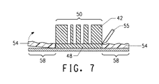
図7に示すとおり、本発明の方法は、光重合性層14の未露光領域54(マスク20の非画像領域24に対応し、かつ、背面マスク30の無傷領域34に対応する)を、支持材16から、そして、レリーフ部分50から除去することを含み、レリーフ領域50は、印刷フォームとして支持材16上に残る。未露光領域54を、支持材16から、そしてレリーフ部分50から除去する工程は、未露光領域54の光重合性層14の少なくともある程度が除去されて、未露光領域54に光重合性材料の薄い層が形成される処理工程後になされる。たいていの実施形態において、除去工程には、レリーフ領域50の周囲に沿って、光重合性層14を通して、まず切断することにより、処理要素を切断し、光重合性層14の未露光領域54を、支持材16から、そして、レリーフ領域50から分離することが含まれる。切断は、ページレイアウトデータに基づいて、手で、またはコンピュータ駆動切断デバイスにより切断することができる。たいていの実施形態において、処理要素は、コンピュータに接続された自動切断テーブルに配置され、ナイフまたはブレードまたは切断器具55が、未露光領域54に隣接しているレリーフ領域50の周囲に沿って光重合性層14を切断するが、下にある支持材16は切断しない。光重合性層14は、その厚さを貫いて深さ方向に切断され、レリーフ領域を、周囲または隣接する未露光領域54から分離することができる。光重合性層14の未露光領域54の、レリーフ領域50からの、そして、未露光領域54の支持材16からの分離は、手で、または好適な剥離または分離デバイスによっても、容易に行うことができる。背面露光は、光重合性層と支持材間の接着力を改善し、背面マスクは、支持材の光重合性層を選択的に露光するため、レリーフ領域50での光重合性層の支持材への接着力は、未露光領域54での光重合性層の支持材への接着力と異なり、後の工程において、未露光領域54での光ポリマー層の除去が促される。光重合性層14の未露光領域54は、支持材16によく接着せず、支持材から容易に剥離または持ち上げるのに好適な厚さを有しているため、レリーフ領域50は支持材上に残る。本発明の除去工程で、未露光領域54の厚さは、処理前の感光性要素の光重合性層の(未加工)厚さより薄く、未露光領域の容易な取扱いならびに支持材およびレリーフ領域からの分離をするため、フロアより薄い、または略等しい厚さである。ある実施形態において、支持材16は、レリーフ領域50の側面の端の1つ以上から伸びて、レリーフ領域50の周縁部58を形成することができる。特に好適な切断テーブルは、EskoArtwork製Kongsbergデジタル変換テーブルである。
As shown in FIG. 7, the method of the present invention supports the
本発明の方法は、任意で、1つのレリーフ領域を、隣接するレリーフ領域から分離する第2の切断を含み、これによって、1つ以上の複合フォームの製造において、2つ以上の別の印刷フォームを、感光性要素から与えることができる。第2の切断は、隣接するレリーフ領域50間の位置でなされ、支持材16は、レリーフ領域50のそれぞれの1つ以上の側面の端から伸び得、レリーフ領域50のそれぞれの周縁部58を形成し得る。たいていの実施形態において、第2の切断は、隣接するレリーフ領域間のほぼ中ほどである。たいていの実施形態において、第2の切断によって、レリーフ領域50の周囲を囲む支持材の周縁部が与えられる。図8に示すとおり、レリーフ領域50と支持材16の周縁部58を含む印刷フォームは、印刷シリンダ(図示せず)に装着するためのシートキャリア60に装着されている。支持材の周縁部は、レリーフ領域を、複合印刷フォームに用いるキャリアに確実に装着するための追加の接触表面を提供する。さらに、レリーフ領域を囲む支持材の周縁部は、レリーフ領域または印刷フォームを、印刷中、インク溶剤による攻撃から保護する周囲を提供する。インク溶剤は、キャリアと支持材間の接着剤を、レリーフ領域を囲む周縁部の端部で攻撃する恐れがあるが、これは、印刷フォームのキャリアへの保持にあまり影響しない。印刷フォームの画像領域を囲む支持材の周縁部は、印刷フォームの容易な取扱いと、キャリアへの装着を可能とする十分に広いものであり、印刷フォームのキャリアへの改善された接着力を確保するため、印刷フォームの広い接触領域を与える。
The method of the present invention optionally includes a second cut that separates one relief area from an adjacent relief area, thereby producing two or more separate printing forms in the production of one or more composite foams. From the photosensitive element. A second cut is made at a location between
一実施形態において、非画像領域24に対応する光重合性層14の未露光領域54は、要素10から分離または除去され、第2の切断が、隣接するレリーフ領域間の位置で、支持材16を通して切断する。他の実施形態において、第2の切断は、未露光領域54が除去される前であり、第2の切断が、光重合性層14の未露光領域54を通して、そして、隣接するレリーフ領域間の位置で、支持材16を通して切断する。
In one embodiment, the
ある実施形態において、本発明の方法は、感光性要素に隣接するマスクを提供し、化学線不透過要素から背面マスクを形成し、感光性要素および背面マスクを組み立てて、背面マスクの無傷領域を、前側マスクの非画像領域と並べ、組立体の感光性要素に、前側マスクおよび背面マスクを通して、化学線を露光し、露光要素を処理して、フロアを備えた硬化部分のレリーフ領域を形成する工程を含み、光重合性層の少なくともある程度は、未露光領域で支持材に残り、未露光領域は支持材およびレリーフ領域から除去され、レリーフ領域は、印刷フォームを形成する支持材に残る。ある他の実施形態において、本発明の方法は、感光性要素に隣接するマスクを提供し、化学線不透過要素から背面マスクを形成し、感光性要素および背面マスクを組み立てて、背面マスクの無傷領域を、前側マスクの非画像領域と並べ、組立体の感光性要素に、前側マスクおよび背面マスクを通して、化学線を露光し、露光要素を処理して、フロアを備えた硬化部分のレリーフ領域を形成し、光重合性層の少なくともある程度は、未露光領域で支持材に残り、未露光領域を、支持材およびレリーフ領域から、レリーフ領域の周囲に沿った光重合性層を通した第1の切断により除去し、未露光領域をレリーフ領域および支持材から分離する工程を含み、レリーフ領域は、支持材に残り、任意で、支持材の周縁部は、レリーフ領域から伸びて、印刷フォームを形成する。本実施形態において、第1の切断と分離を含む除去工程は、処理工程の後に順番になされる。 In certain embodiments, the method of the present invention provides a mask adjacent to the photosensitive element, forms a back mask from the actinic radiation opaque element, and assembles the photosensitive element and the back mask to provide an intact area of the back mask. Align with the non-image area of the front mask, expose the photosensitive element of the assembly through the front and back masks with actinic radiation and process the exposure element to form a relief area of the hardened portion with the floor At least some of the photopolymerizable layer remains on the support in the unexposed areas, the unexposed areas are removed from the support and the relief areas, and the relief areas remain on the support forming the printing form. In certain other embodiments, the method of the present invention provides a mask adjacent to the photosensitive element, forms a back mask from the actinic radiation opaque element, assembles the photosensitive element and the back mask to provide an intact back mask. The area is aligned with the non-image area of the front mask, and the photosensitive element of the assembly is exposed to actinic radiation through the front and back masks, and the exposed element is processed to provide a relief area in the hardened portion with the floor. Forming and at least some of the photopolymerizable layer remains on the support material in the unexposed area, and the unexposed area passes from the support material and the relief area through the photopolymerizable layer along the periphery of the relief area. Removing by cutting and separating the unexposed areas from the relief area and the support material, wherein the relief area remains on the support material, and optionally the peripheral edge of the support material extends from the relief area and is printed. To form a foam. In this embodiment, the removal process including the first cutting and separation is performed in order after the processing process.
処理後の感光性要素は、化学線に均一に後露光すると、確実に、光重合プロセスが完了され、要素が印刷および保管中安定なままとすることができる。この後露光工程は、全体露光と同じ放射線源を利用することができる。粘着除去は、感光印刷要素の表面がまだ粘着性であるとき適用できる任意の後現像処理であり、かかる粘着性は、概して、後露光で除去されない。粘着性は、臭素または塩素溶液で処理する等、業界において周知の方法により排除することができる。好ましくは、粘着除去は、(特許文献33)およびGibsonによる(特許文献34)に開示されているとおり、300nm以下の波長を有する放射線源への露光によりなされる。 The processed photosensitive element can be uniformly post-exposed to actinic radiation to ensure that the photopolymerization process is complete and the element remains stable during printing and storage. This post-exposure step can utilize the same radiation source as the overall exposure. Tack removal is any post-development process that can be applied when the surface of the photosensitive printing element is still tacky, and such tack is generally not removed by post-exposure. Tackiness can be eliminated by methods well known in the industry, such as treatment with bromine or chlorine solutions. Preferably, the detacking is done by exposure to a radiation source having a wavelength of 300 nm or less, as disclosed in (Patent Document 33) and Gibson (Patent Document 34).
キャリア60は、印刷フォームの位置を保持および維持し、印刷のための、支持材16の周縁部58を備えたレリーフ領域50を含む。たいていの実施形態において、キャリアはシート形態にあるが、限定されず、円柱形形態を含むことができる。シート形態のキャリアは、キャリアのサイズまたは平面を決める長さおよび幅寸法を備えた側面の端を有しており、長さおよび幅は、その厚さより大幅に大きく、2つの実質的に平坦な対向する主面を有している。キャリアが円柱形の実施形態においては、サイズは、円柱形キャリアの外側表面の表面積を基準とする。キャリアは、本発明により作製された画像領域の配置および位置合わせのためのマーキングまたはインジケータを含んでいてもよい。
The carrier 60 includes a
シートキャリアとして用いるのに好適な材料は、印刷シリンダ周囲を包めるよう可撓性で、特に、印刷中の変形および伸張に対する抵抗性があり、処理の際の変形またはサイズ変化に対して抵抗性がある任意のものとすることができる。キャリアとして好適な材料としては、これらに限られるものではないが、ビニルプラスチック、リノリウム、金属およびポリマーフィルム、例えば、ポリエステルが例示される。キャリアの好適な厚さは、0.005〜0.185インチ(0.013〜0.47cm)である。多くの実施形態において、キャリアは、0.010〜0.030インチ(0.025〜0.076cm)の厚さを有するポリ塩化ビニル(PVC)またはポリエチレンテレフタレートのポリマーフィルムである。円柱形キャリアとして用いるのに好適な材料は、印刷スリーブまたはスリーブと一般的に呼ばれる円柱印刷フォームに用いられる任意の支持材とすることができる。スリーブまたは円柱支持材の種類は限定されない。スリーブは、可撓性材料の単一層または多層から形成してよい。ある実施形態において、ポリマーフィルムで作製された可撓性スリーブが好適である。他の実施形態において、ニッケルのような金属またはガラスエポキシのスリーブが好適である。スリーブは、10ミル(0.025cm)未満〜80ミル(0.203cm)以上の壁厚さを有することができる。キャリアシートと反対の端部は、例えば、溶解溶融、テープ留め、ステッチ、クランプ、ホチキス留め、テープ留め、糊付けおよび縫製等の任意の適切な手段により結合して、円柱形キャリアを形成することができるものとも考えられる。キャリアは、画像領域をキャリアシートに固定する前、好ましくは、後に、円柱形へと形成することができる。 Suitable materials for use as a sheet carrier are flexible to wrap around the printing cylinder, in particular resistant to deformation and stretching during printing, and resistant to deformation or size changes during processing. It can be any arbitrary one. Suitable materials for the carrier include, but are not limited to, vinyl plastic, linoleum, metal and polymer films such as polyester. The preferred thickness of the carrier is 0.005 to 0.185 inches (0.013 to 0.47 cm). In many embodiments, the carrier is a polyvinyl chloride (PVC) or polyethylene terephthalate polymer film having a thickness of 0.010 to 0.030 inches (0.025 to 0.076 cm). A suitable material for use as a cylindrical carrier can be any support used in a cylindrical printing form, commonly referred to as a printing sleeve or sleeve. The type of sleeve or cylindrical support is not limited. The sleeve may be formed from a single layer or multiple layers of flexible material. In certain embodiments, a flexible sleeve made of a polymer film is preferred. In other embodiments, a metal or glass epoxy sleeve such as nickel is suitable. The sleeve can have a wall thickness of less than 10 mils (0.025 cm) to 80 mils (0.203 cm) or more. The opposite end of the carrier sheet may be joined by any suitable means such as melt melting, tape fastening, stitching, clamping, stapling, tape fastening, gluing and sewing to form a cylindrical carrier. It can also be considered possible. The carrier can be formed into a cylindrical shape before, preferably after, fixing the image area to the carrier sheet.
キャリア(シート形態)は、少なくとも2つの開口部または穴を配置することのできる先端または前縁を有する。少なくとも2つの穴は、先端近くに平行に位置する列の間隔で並んでいる。穴のサイズ、形状および数(少なくとも2つ以上の穴)は、本発明において特に限定されない。キャリアの先端にある少なくとも2つの穴によって、キャリアを印刷シリンダ(およびレーザー露光装置)に位置合わせすることができる。キャリアの先端の少なくとも2つの穴を用いて、装着するために、キャリアを装着バーに固定することもできる。キャリアの先端の穴は、従来の機器により、機械加工、穿孔またはドリル加工することができる。従来の穿孔機器は、Stoesser、Burgess IndustriesおよびCarlson等の印刷業界のフィルム穿孔の製造業者からのものである。キャリアの先端のそれぞれに穴を穿孔した後、単一の感光性要素をキャリアに隣接配置する。たいていの実施形態において、感光性要素は、キャリアの上部に配置される。 The carrier (sheet form) has a tip or leading edge in which at least two openings or holes can be placed. The at least two holes are lined up in rows spaced in parallel near the tip. The size, shape, and number of holes (at least two or more holes) are not particularly limited in the present invention. The carrier can be aligned with the printing cylinder (and laser exposure apparatus) by at least two holes at the tip of the carrier. The carrier can also be secured to the mounting bar for mounting using at least two holes at the tip of the carrier. The hole at the tip of the carrier can be machined, drilled or drilled with conventional equipment. Conventional perforating equipment is from the film perforation manufacturers in the printing industry such as Stoesser, Burgess Industries and Carlson. After drilling a hole in each of the carrier tips, a single photosensitive element is placed adjacent to the carrier. In most embodiments, the photosensitive element is placed on top of the carrier.
キャリアが円柱形である実施形態において、キャリアは、画像形成またはその他装置と関連する支持材シリンダ上に(予備)装着することができ、1つの感光性要素が、円柱キャリアに隣接配置される。画像領域は、画像領域の1つ以上の端部をキャリアにテープ留めまたはピン留めすることにより装着しながら、キャリアの定位置に保持することができる。 In embodiments where the carrier is cylindrical, the carrier can be (preliminarily) mounted on a support cylinder associated with the imaging or other device, with one photosensitive element positioned adjacent to the cylindrical carrier. The image area can be held in place on the carrier while being attached by tape or pinning one or more edges of the image area to the carrier.
作製された印刷フォームは、当業者に公知の多くの手段のいずれかを用いて、固定または装着することができる。たいていの実施形態には、両面接着テープまたはその他好適な接着剤または糊を、画像領域、キャリアまたは両方に適用することが含まれる。画像領域をキャリアに固定する他の方法も本発明に包含され、これらに限られるものではないが、ピン留め、ステッチおよびホチキス留めが含まれる。ある実施形態において、両面接着テープは、画像領域の支持材に適用される。他の実施形態において、支持材は、前駆体から除去され、両面接着テープが、前に支持材があった前駆体表面に適用される。 The produced printing form can be fixed or mounted using any of a number of means known to those skilled in the art. Most embodiments include applying double-sided adhesive tape or other suitable adhesive or glue to the image area, carrier, or both. Other methods of securing the image area to the carrier are encompassed by the present invention and include, but are not limited to, pinning, stitching and stapling. In some embodiments, the double-sided adhesive tape is applied to the image area support. In other embodiments, the support is removed from the precursor and a double-sided adhesive tape is applied to the precursor surface that previously had the support.
感光性要素
感光性要素または前駆体は、光重合性組成物の少なくとも1層を含む。「感光」という用語には、少なくとも1つの感光層が、化学線に応答して、1つまたは複数の反応、特に、光化学反応を開始することのできる任意の系が包含される。ある実施形態において、感光性要素は、光重合性層の支持材を含む。ある実施形態において、光重合性層は、バインダー、少なくとも1つのモノマーおよび光開始剤を含むエラストマー層である。ある実施形態において、感光性要素は、支持材の反対にある光重合性層に隣接する化学線不透過材料としても機能し得る赤外線感受性の層を含む。
Photosensitive Element The photosensitive element or precursor comprises at least one layer of a photopolymerizable composition. The term “photosensitive” includes any system in which at least one photosensitive layer can initiate one or more reactions, particularly photochemical reactions, in response to actinic radiation. In certain embodiments, the photosensitive element includes a support for the photopolymerizable layer. In certain embodiments, the photopolymerizable layer is an elastomeric layer that includes a binder, at least one monomer, and a photoinitiator. In certain embodiments, the photosensitive element includes an infrared sensitive layer that can also function as an actinic radiation opaque material adjacent to the photopolymerizable layer opposite the support.
特に別記しない限り、「感光性要素」という用語には、放射線への露光を行い、処理して、印刷に好適な表面を形成することのできる印刷前駆体が包含される。別記しない限り、「感光性要素」および「印刷フォーム」には、これらに限られるものではないが、平シート、プレート、プレート・オン・スリーブおよびプレート・オン・キャリアをはじめとする印刷に好適となる、または印刷に好適な任意の形態の要素または構造が含まれる。感光性要素から得られる印刷フォームには、フレキソおよび凸版印刷等のレリーフ印刷の最終印刷用途があるものと考えられる。レリーフ印刷は、印刷フォームが画像領域から印刷する印刷方法であり、印刷フォームの画像領域は隆起しており、非画像領域は凹んでいる。 Unless otherwise stated, the term “photosensitive element” includes printing precursors that can be exposed to radiation and processed to form a surface suitable for printing. Unless otherwise noted, “photosensitive elements” and “printing forms” are suitable for printing including, but not limited to, flat sheets, plates, plate-on-sleeves, and plate-on-carriers. Any form or element suitable for printing or printing is included. It is believed that printing forms obtained from photosensitive elements have final printing applications for relief printing such as flexographic and relief printing. Relief printing is a printing method in which a printing form prints from an image area, where the image area of the printing form is raised and the non-image area is recessed.
感光性要素は、光重合性組成物の少なくとも1層を有している。本明細書で用いる「光重合性」という用語は、光重合性、光架橋性または両方である系を包含することを意図する。光重合性層は、バインダー、少なくとも1つのモノマーおよび光開始剤を含む組成物で形成された固体エラストマー層である。光開始剤は、化学線に対する感受性を有する。本明細書全体にわたって、化学光には、紫外線および/または可視光が含まれるであろう。光重合性組成物の固体層は、1つ以上の溶液および/または熱により処理して、フレキソ印刷に好適なレリーフを形成する。本明細書で用いる、「固体」という用語は、明確な体積と形状を有し、その体積または形状を変える傾向のある力に抵抗する層の物理的状態を示す。光重合性組成物の層は、約5℃〜約30℃の温度である室温で固体である。たいていの実施形態において、感光性要素の光重合性組成物の固体層は未重合であるが、光重合性組成物が、重合(すなわち、光硬化または硬化)、または重合(すなわち、フロア)と未重合の両方であってもよいある実施形態を含むことができる。 The photosensitive element has at least one layer of a photopolymerizable composition. As used herein, the term “photopolymerizable” is intended to encompass systems that are photopolymerizable, photocrosslinkable, or both. The photopolymerizable layer is a solid elastomer layer formed of a composition comprising a binder, at least one monomer and a photoinitiator. Photoinitiators are sensitive to actinic radiation. Throughout this specification, actinic light will include ultraviolet light and / or visible light. The solid layer of the photopolymerizable composition is treated with one or more solutions and / or heat to form a relief suitable for flexographic printing. As used herein, the term “solid” refers to the physical state of a layer that has a well-defined volume and shape and resists forces that tend to change its volume or shape. The layer of photopolymerizable composition is solid at room temperature, which is a temperature of about 5 ° C to about 30 ° C. In most embodiments, the solid layer of the photopolymerizable composition of the photosensitive element is unpolymerized, but the photopolymerizable composition is polymerized (ie photocured or cured), or polymerized (ie floor). Certain embodiments may be included that may be both unpolymerized.
バインダーは限定されず、単一ポリマーまたはポリマーの混合物とすることができる。ある実施形態において、バインダーは、エラストマーバインダーである。他の実施形態において、バインダーは、化学線に露光するとエラストマーとなる。バインダーとしては、ポリイソプレン、1,2−ポリブタジエン、1,4−ポリブタジエン、ブタジエン/アクリロニトリルおよびジエン/スチレン熱可塑性−エラストマーブロックコポリマーをはじめとする共役ジオレフィン炭化水素の天然または合成ポリマーが挙げられる。ある実施形態において、バインダーはA−B−Aタイプのブロックコポリマーのエラストマーブロックコポリマーであり、Aは非エラストマーブロックを表わし、Bはエラストマーブロックを表わす。非エラストマーブロックAは、例えば、ポリスチレン等のビニルポリマーとすることができる。エラストマーブロックBとしては、ポリブタジエンおよびポリイソプレンが例示される。バインダーは、水性、半水性、水または有機溶剤洗浄溶液に可溶、膨潤または分散性のものとすることができる。概して、洗浄現像に好適なエラストマーバインダーはまた、光重合性層の未重合領域が、加熱の際に軟化、溶融または流動する熱処理に用いるのにも好適である。 The binder is not limited and can be a single polymer or a mixture of polymers. In certain embodiments, the binder is an elastomeric binder. In other embodiments, the binder becomes an elastomer when exposed to actinic radiation. Binders include natural or synthetic polymers of conjugated diolefin hydrocarbons including polyisoprene, 1,2-polybutadiene, 1,4-polybutadiene, butadiene / acrylonitrile and diene / styrene thermoplastic-elastomer block copolymers. In some embodiments, the binder is an elastomeric block copolymer of an ABA type block copolymer, A represents a non-elastomeric block, and B represents an elastomeric block. The non-elastomeric block A can be, for example, a vinyl polymer such as polystyrene. Examples of the elastomer block B include polybutadiene and polyisoprene. The binder can be soluble, swellable or dispersible in aqueous, semi-aqueous, water or organic solvent cleaning solutions. In general, elastomer binders suitable for wash development are also suitable for use in heat treatments where the unpolymerized areas of the photopolymerizable layer soften, melt or flow upon heating.
レリーフ印刷に望ましい特性が得られる限りは、単一エラストマー材料か、材料の組み合わせを、エラストマー層に用いることができる。エラストマー材料の例は、(非特許文献1)に記載されている。多くの場合、エラストマー層を処方するのに熱可塑性エラストマー材料を用いるのが望ましいであろう。熱可塑性エラストマー層を光化学的に補強するときは、層はエラストマーのままであるが、かかる補強後はもはや熱可塑性ではない。これには、限定されるものではないが、ブタジエンとスチレンのコポリマー、イソプレンとスチレンのコポリマー、スチレン−ジエン−スチレントリブロックコポリマー等のエラストマー材料が含まれる。 A single elastomeric material or a combination of materials can be used for the elastomeric layer as long as the desired properties for relief printing are obtained. Examples of elastomeric materials are described in (Non-Patent Document 1). In many cases, it will be desirable to use a thermoplastic elastomer material to formulate the elastomer layer. When a thermoplastic elastomer layer is photochemically reinforced, the layer remains an elastomer but is no longer thermoplastic after such reinforcement. This includes, but is not limited to, elastomeric materials such as copolymers of butadiene and styrene, copolymers of isoprene and styrene, styrene-diene-styrene triblock copolymers, and the like.
光重合性組成物は、透明な曇りのない感光層が生成される範囲まで、バインダーと相溶性のある付加重合可能な少なくとも1つの化合物を含有する。付加重合可能な少なくとも1つの化合物はまた、モノマーとも呼ぶこともできる。光重合性組成物に用いることのできるモノマーは業界に周知されており、これらに限られるものではないが、少なくとも1つの末端エチレン基を有する付加重合エチレン化不飽和化合物が挙げられる。組成物は、単一モノマーまたはモノマーの組み合わせを含有することができる。モノマーは、好適なエラストマーおよびその他特性を光重合性組成物に与えるために、当業者であれば、適切に選択することができる。 The photopolymerizable composition contains at least one addition-polymerizable compound that is compatible with the binder to the extent that a clear, non-cloudy photosensitive layer is produced. At least one compound capable of addition polymerization can also be referred to as a monomer. Monomers that can be used in the photopolymerizable composition are well known in the art and include, but are not limited to, addition-polymerized ethylenically unsaturated compounds having at least one terminal ethylene group. The composition can contain a single monomer or a combination of monomers. Monomers can be appropriately selected by those skilled in the art to provide suitable elastomeric and other properties to the photopolymerizable composition.
光開始剤は、過度に停止することなく、1つまたは複数のモノマーの重合を開始するフリーラジカルを生成する、化学線に感受性のある任意の単一の化合物または化合物の組み合わせとすることができる。光開始剤の公知の部類のいずれか、特に、フリーラジカル光開始剤を用いてよい。あるいは、光開始剤は、放射線により活性化された増感剤によりそのようになされると、化合物の1つが、フリーラジカルを与える化合物の混合物であってもよい。主露光(後露光およびバックフラッシュも)の光開始剤は、310〜400nm、好ましくは、345〜365nmの可視または紫外線に感受性があるのが好ましい。 The photoinitiator can be any single compound or combination of compounds sensitive to actinic radiation that generates free radicals that initiate the polymerization of one or more monomers without undue termination. . Any of the known classes of photoinitiators, in particular free radical photoinitiators, may be used. Alternatively, the photoinitiator may be a mixture of compounds that, when made so with a sensitizer activated by radiation, one of the compounds provides a free radical. The photoinitiator for main exposure (also post-exposure and backflash) is preferably sensitive to visible or ultraviolet light at 310-400 nm, preferably 345-365 nm.
光重合性組成物は、必要な最終特性に応じて、他の添加剤を含有することができる。光重合性組成物への追加添加剤としては、増感剤、可塑材、レオロジー修正剤、熱重合防止剤、着色剤、処理助剤、酸化防止剤、オゾン劣化防止剤、染料およびフィラーが挙げられる。 The photopolymerizable composition can contain other additives depending on the final properties required. Additional additives to the photopolymerizable composition include sensitizers, plasticizers, rheology modifiers, thermal polymerization inhibitors, colorants, processing aids, antioxidants, antiozonants, dyes and fillers. It is done.
光重合性層の厚さは、印刷最終用途に応じて、広い範囲で変えることができる。ある実施形態において、感光層は、約0.005インチ〜約0.250インチ以上(0.013〜0.64cm以上)の厚さを有することができる。光重合性層の典型的な厚さは、約0.045インチ〜約0.250インチ(約0.025cm〜約0.64cm)である。波形印刷のためのようなある実施形態において、感光層は、約0.100インチ〜約0.300インチ(0.25〜0.76cm)の厚さを有することができる。 The thickness of the photopolymerizable layer can be varied within a wide range depending on the final printing application. In certain embodiments, the photosensitive layer can have a thickness of about 0.005 inches to about 0.250 inches or more (0.013 to 0.64 cm or more). A typical thickness for the photopolymerizable layer is from about 0.045 inches to about 0.250 inches (about 0.025 cm to about 0.64 cm). In certain embodiments, such as for corrugated printing, the photosensitive layer can have a thickness of about 0.100 inches to about 0.300 inches (0.25-0.76 cm).
感光性要素は、典型的に、光重合性組成物の層に隣接する支持材を含む。支持材は、印刷フォームを作製するのに用いる感光性要素と共に従来から用いられる何らかの材料または材料の組み合わせで構成することができる。ある実施形態において、支持材は、支持材を通した露光に適合するために、化学線を透過する。好適な支持材材料としては、付加ポリマーおよび鎖状縮合ポリマーにより形成されたようなポリマーフィルム、透明発泡体および布、例えば、ファイバーガラスが例示される。特定の最終用途条件下では、アルミニウム、鋼およびニッケル等の金属を、金属支持材は、放射線を透過しないが、支持材として用いてもよい。ある実施形態において、支持材はポリエステルフィルムである。一実施形態において、支持材は、ポリエチレンテレフタレートフィルムである。ある実施形態において、支持材は、0.002〜0.050インチ(0.0051〜0.127cm)の厚さを有する。他の実施形態において、シート形態の支持材の厚さは、0.003〜0.016インチ(0.0076〜0.040cm)である。 The photosensitive element typically includes a support adjacent to the layer of photopolymerizable composition. The support can be composed of any material or combination of materials conventionally used with photosensitive elements used to make printing forms. In certain embodiments, the support is transparent to actinic radiation in order to be compatible with exposure through the support. Suitable support materials include polymer films such as those formed by addition polymers and chain condensation polymers, transparent foams and fabrics such as fiberglass. Under certain end use conditions, metals such as aluminum, steel and nickel may be used as the support, although the metal support does not transmit radiation. In certain embodiments, the support material is a polyester film. In one embodiment, the support material is a polyethylene terephthalate film. In certain embodiments, the support has a thickness of 0.002 to 0.050 inch (0.0051 to 0.127 cm). In other embodiments, the thickness of the sheet form support is 0.003 to 0.016 inch (0.0076 to 0.040 cm).
任意で、要素は、支持材と光重合性層との間に接着層を有する、または光重合性層に隣接する支持材の表面に接着促進表面を有する。さらに、光重合性層の支持材への接着力は、Feinbergらによる(特許文献3)に開示されているとおり、要素を、支持材を通して、化学線に露光することにより調整することができる。 Optionally, the element has an adhesion layer between the support and the photopolymerizable layer, or has an adhesion promoting surface on the surface of the support adjacent to the photopolymerizable layer. Furthermore, the adhesion of the photopolymerizable layer to the support can be adjusted by exposing the element to actinic radiation through the support, as disclosed in Feinberg et al.
当業者に周知されているとおり、感光性要素は、光重合性層に隣接する、すなわち、支持材と反対の光重合性層の側部に、1つ以上の追加の層を含んでいてもよい。所望の用途に応じて、追加の層は、化学線を不透過または透過してもよく、感光性要素のための1つ以上の機能を有していてもよい。追加の層としては、これらに限られるものではないが、剥離層、エラストマーキャッピング層、バリア層、接着調整層、感光性要素の表面特性を変える層およびこれらの組み合わせが挙げられる。1つ以上の追加の層は、処理中に、全体または一部を除去することができる。1つ以上の追加の層は、感光組成物層をカバー、または部分的にのみカバーしてよい。所望の最終用途に応じて、光重合性層の追加の層を選択し作製するのは当業者であれば分かる。 As is well known to those skilled in the art, the photosensitive element may include one or more additional layers adjacent to the photopolymerizable layer, i.e., on the side of the photopolymerizable layer opposite the support. Good. Depending on the desired application, the additional layers may be opaque or transparent to actinic radiation and may have one or more functions for the photosensitive element. Additional layers include, but are not limited to, release layers, elastomeric capping layers, barrier layers, adhesion control layers, layers that change the surface properties of the photosensitive element, and combinations thereof. One or more additional layers can be removed in whole or in part during processing. One or more additional layers may cover or only partially cover the photosensitive composition layer. One skilled in the art will know to select and make additional layers of the photopolymerizable layer depending on the desired end use.
一実施形態において、感光性要素は、支持材と反対の光重合性層の表面上に配置された化学線不透過層でもある赤外線感受性層を含む。化学放射線不透過層は、光重合性層の表面を実質的にカバーする、または画像形成部分のみをカバーしてよい。化学線不透過層は、光重合性材料の感受性に対応する化学線を実質的に不透過である。化学線不透過層は、バリア層あり、またはなしで用いることができる。バリア層と共に用いる場合、バリア層は、光重合層と、放射線不透過層との間に配置される。存在すると、バリア層は、光重合性層と、放射線不透過層との間の材料の移動を最小にすることができる。化学線不透過層はまた、不透過層を選択的に除去または移動することができるレーザー光に対して感受性もある。一実施形態において、化学線不透過層は、赤外レーザー光に対して感受性がある。化学線不透過層は、放射線不透過材料、赤外線吸収材料および任意のバインダーを含む。暗い無機顔料、例えば、カーボンブラックおよびグラファイト、顔料、金属および金属合金の混合物は、概して、赤外線感受性材料と放射線不透過材料の両方として機能する。任意のバインダーは、限定されないポリマー材料である。化学線不透過層の厚さは、概して、約20オングストローム〜約50マイクロメートルである感受性と不透過性の両方を最適化する範囲内のものとする。化学線不透過層は、化学線を効果的にブロックし、下にある光重合性層の重合のために、2.0を超える透過光学密度を有する。 In one embodiment, the photosensitive element includes an infrared sensitive layer that is also an actinic radiation opaque layer disposed on the surface of the photopolymerizable layer opposite the support. The actinic radiation opaque layer may substantially cover the surface of the photopolymerizable layer or may cover only the imaging portion. The actinic radiation opaque layer is substantially opaque to actinic radiation that corresponds to the sensitivity of the photopolymerizable material. The actinic radiation opaque layer can be used with or without a barrier layer. When used with a barrier layer, the barrier layer is disposed between the photopolymerizable layer and the radiopaque layer. When present, the barrier layer can minimize material transfer between the photopolymerizable layer and the radiopaque layer. The actinic radiation opaque layer is also sensitive to laser light that can selectively remove or move the opaque layer. In one embodiment, the actinic radiation opaque layer is sensitive to infrared laser light. The actinic radiation opaque layer includes a radiopaque material, an infrared absorbing material, and an optional binder. Dark inorganic pigments such as carbon black and graphite, mixtures of pigments, metals and metal alloys generally function as both infrared sensitive and radiopaque materials. The optional binder is a non-limiting polymer material. The thickness of the actinic radiation opaque layer is generally in the range of about 20 angstroms to about 50 micrometers to optimize both sensitivity and opacity. The actinic radiation opaque layer effectively blocks actinic radiation and has a transmission optical density greater than 2.0 due to polymerization of the underlying photopolymerizable layer.
本発明の感光印刷要素は、さらに、一時的なカバーシートを、要素の最外層の上部に有していてもよい。カバーシートの1つの目的は、保管および取扱いの間、感光印刷要素の最上層を保護することである。カバーシートに好適な材料としては、剥離層の代わりにすることのできるポリスチレン、ポリエチレン、ポリプロピレン、ポリカーボネート、フルオロポリマー、ポリアミドまたはポリエステルの薄膜が例示される。カバーシートは、ポリエステル、例えば、Mylar(登録商標)ポリエチレンテレフタレートフィルムから作製するのが好ましく、最も好ましくは、カバーシートは、5−ミルのMylar(登録商標)である。 The photosensitive printing element of the present invention may further have a temporary cover sheet on top of the outermost layer of the element. One purpose of the cover sheet is to protect the top layer of the photosensitive printing element during storage and handling. Examples of suitable materials for the cover sheet include polystyrene, polyethylene, polypropylene, polycarbonate, fluoropolymer, polyamide or polyester thin films that can be substituted for the release layer. The cover sheet is preferably made from polyester, such as Mylar® polyethylene terephthalate film, most preferably the cover sheet is 5-mil Mylar®.
感光性要素の露光(および処理)後、複合印刷フォームの感光性要素は、約20〜約80ショアAのデュロメータを有する。ある実施形態において、複合印刷フォームの(露光および処理)感光性要素は、30〜50ショアAのデュロメータを有する。ショアデュロメータは、押込みに対する材料の抵抗性の尺度である。ショアAのデュロメータは、軟性ゴムまたはエラストマー材料に典型的に用いられる基準であり、値が大きいと、透過に対する抵抗性が大きい。印刷フォームのデュロメータは、DIN53,505またはASTM D2240−00に記載された標準化された手順に従って測定することができる。
なお、本発明は、特許請求の範囲を含め、以下の発明を包含する。
1.a)感光性要素に隣接して支持材と反対の光重合性層の側面上に配置される、画像領域と非画像領域とを含むフロントマスクを提供し、
b)化学線不透過要素から、無傷領域と、カットアウト領域とを有する背面マスクを形成し、
c)工程a)の要素の前記支持材に隣接して前記背面マスクを配置し、前記無傷領域を前記非画像領域と位置合わせし、
d)工程c)の要素を、前記フロントマスクを通して化学線に露光して、前記画像領域に対応する前記光重合性層の硬化部分を形成し、
e)工程c)の要素を、前記背面マスクを通して化学線に露光して、前記硬化部分に隣接する硬化フロアを形成し、ならびに前記非画像領域に対応する前記光重合性層の未露光部分を提供し、
f)露光工程d)およびe)後に得られる要素を処理して、前記フロアを備えた前記硬化部分のレリーフ領域を形成し、ここで前記光重合性層が少なくともある程度、前記支持材の前記未露光領域に残り、
g)前記光重合性層の前記未露光領域を、前記支持材からおよび前記レリーフ領域から除去し、前記レリーフ領域が前記支持材上に残って、印刷フォームを形成することを含む、支持材上に光重合性層を含む感光性要素から印刷フォームを製造する方法。
2.工程d)および工程e)を同時に、または任意の順で続けて行う1に記載の方法。
3.工程f)の後、前記フロアはある厚さを有し、前記支持材の前記未露光領域に残る前記光重合性層は、前記フロアの厚さと同じ、または実質的に同じ厚さを有する1に記載の方法。
4.工程f)の後、前記フロアはある厚さを有し、前記支持材の前記未露光領域に残る前記光重合性層は、前記フロアの厚さより薄い厚さを有する1に記載の方法。
5.前記支持材の前記未露光領域に残る前記光重合性層の厚さは、前記フロアの厚さより約1〜約20ミル薄い4に記載の方法。
6.工程f)の後、前記フロアはある厚さを有し、前記支持材の前記未露光領域に残る前記光重合性層は、約50ミル〜前記フロアの厚さと略同じ厚さを有する1に記載の方法。
7.工程f)の後、前記フロアはある厚さを有し、前記支持材の前記未露光領域に残る前記光重合性層は、約40ミル〜前記フロアの厚さと略同じ厚さを有する1に記載の方法。
8.工程f)の前、前記要素の前記光重合性層は、約90〜280ミルの厚さを有する1に記載の方法。
9.前記除去工程g)が、
g1)前記レリーフ領域の周囲に沿った前記光重合性層を通した第1の切断を含む、工程f)の要素を切断することと、
g2)前記光重合性層の前記未露光領域を、前記レリーフ領域および前記支持材から分離することと
を含む1に記載の方法。
10.工程g)が、前記未露光領域における前記光重合性層と支持材を通した第2の切断をさらに含み、第2の切断により前記レリーフ領域の少なくとも1つの側面の端から伸びる前記支持材の周縁部が形成される9に記載の方法。
11.工程g)の後、前記支持材の周縁部が、前記レリーフ領域の前記周囲の少なくとも1つの側面の端を超えて伸びる1に記載の方法。
12.前記マスクを提供する工程a)が、前記支持材と反対の前記光重合性層の側面上に配置された化学線不透過層の、前記感光性要素上の一体化マスクを形成することを含む1に記載の方法。
13.少なくとも1つの位置合わせマークを、前記非画像領域に作成し、
少なくとも1つの位置合わせマークを、前記背面マスクの前記無傷領域に作成することをさらに含み、
前記無傷領域の、前記非画像領域との位置合わせは、前記非画像領域の前記少なくとも1つの位置合わせマークを、前記無傷領域の前記少なくとも1つの位置合わせマークと位置合わせすることにより実施される1に記載の方法。
After exposure (and processing) of the photosensitive element, the photosensitive element of the composite printing form has a durometer of about 20 to about 80 Shore A. In certain embodiments, the photosensitive element of the composite printing form (exposure and processing) has a durometer of 30-50 Shore A. A shore durometer is a measure of the resistance of a material to indentation. The Shore A durometer is a standard typically used for soft rubber or elastomeric materials, with higher values providing greater resistance to transmission. The durometer of the printed form can be measured according to standardized procedures described in DIN 53,505 or ASTM D2240-00.
In addition, this invention includes the following invention including a claim.
1. a) providing a front mask comprising an image area and a non-image area disposed on a side of the photopolymerizable layer adjacent to the photosensitive element opposite the support;
b) forming a back mask having an intact area and a cut-out area from the actinic radiation opaque element;
c) placing the back mask adjacent to the support of the element of step a) and aligning the intact area with the non-image area;
d) exposing the elements of step c) to actinic radiation through the front mask to form a cured portion of the photopolymerizable layer corresponding to the image area;
e) exposing the element of step c) to actinic radiation through the back mask to form a cured floor adjacent to the cured portion, and unexposed portions of the photopolymerizable layer corresponding to the non-image areas; Offer to,
f) processing the elements obtained after the exposure steps d) and e) to form a relief region of the hardened part with the floor, wherein the photopolymerizable layer is at least partially free of the unsupported part of the support material. Remaining in the exposure area,
g) removing the unexposed areas of the photopolymerizable layer from the support material and from the relief area, the relief area remaining on the support material to form a printing form; A method for producing a printing form from a photosensitive element comprising a photopolymerizable layer.
2. 2. The method according to 1, wherein step d) and step e) are carried out simultaneously or in any order.
3. After step f), the floor has a thickness, and the photopolymerizable layer remaining in the unexposed areas of the support has the same or substantially the same thickness as the floor 1 The method described in 1.
4). The method according to 1, wherein after step f), the floor has a thickness and the photopolymerizable layer remaining in the unexposed areas of the support has a thickness less than the thickness of the floor.
5. The method of claim 4, wherein the thickness of the photopolymerizable layer remaining in the unexposed areas of the support is about 1 to about 20 mils thinner than the thickness of the floor.
6). After step f), the floor has a thickness, and the photopolymerizable layer remaining in the unexposed area of the support has a thickness of about 50 mils to 1 having a thickness substantially the same as the floor thickness. The method described.
7). After step f), the floor has a thickness, and the photopolymerizable layer remaining in the unexposed area of the support is about 40 mils to 1 having a thickness substantially the same as the floor thickness. The method described.
8). The method of 1, wherein, prior to step f), the photopolymerizable layer of the element has a thickness of about 90 to 280 mils.
9. Said removal step g)
g1) cutting the element of step f) including a first cut through the photopolymerizable layer along the periphery of the relief region;
g2) The method according to 1, comprising separating the unexposed area of the photopolymerizable layer from the relief area and the support material.
10. Step g) further comprises a second cut through the photopolymerizable layer and a support material in the unexposed area, wherein the second cut extends from the end of at least one side of the relief area. 10. The method according to 9, wherein the peripheral edge is formed.
11. The method according to 1, wherein, after step g), the periphery of the support material extends beyond the edge of at least one side surface of the periphery of the relief region.
12 Step a) providing the mask comprises forming an integral mask on the photosensitive element of an actinic radiation opaque layer disposed on the side of the photopolymerizable layer opposite the support. The method according to 1.
13. Creating at least one alignment mark in the non-image area;
Further comprising creating at least one alignment mark in the intact area of the back mask;
The alignment of the intact area with the non-image area is performed by aligning the at least one alignment mark in the non-image area with the at least one alignment mark in the intact area 1. The method described in 1.
10 感光性要素
14 光重合性層
16 支持材
20 マスク
22 画像領域
22a 不透明領域
22b 透明領域
24 非画像領域
24a 不透明領域
30 背面マスク
32 カットアウト領域
34 無傷領域
36 化学線
38 化学線
42 硬化部分
44 未露光部分
48 フロア
50 レリーフ領域
54 未露光領域
55 切断器具
58 周縁部
60 キャリア
DESCRIPTION OF
Claims (1)
b)化学線不透過要素から、無傷領域と、カットアウト領域とを有する背面マスクを形成し、
c)工程a)の要素の前記支持材に隣接して前記背面マスクを配置し、前記無傷領域を前記非画像領域と位置合わせし、
d)工程c)の要素を、前記フロントマスクを通して化学線に露光して、前記画像領域に対応する前記光重合性層の硬化部分を形成し、
e)工程c)の要素を、前記背面マスクを通して化学線に露光して、前記硬化部分に隣接する硬化フロアを形成し、ならびに前記非画像領域に対応する前記光重合性層の未露光部分を提供し、
f)露光工程d)およびe)後に得られる要素を処理して、前記フロアを備えた前記硬化部分のレリーフ領域を形成し、ここで前記光重合性層が少なくともある程度、前記支持材の前記未露光領域に残り、
g)前記光重合性層の前記未露光領域を、前記支持材からおよび前記レリーフ領域から除去し、前記レリーフ領域が前記支持材上に残って、印刷フォームを形成することを含み、
前記除去工程g)が、
g1)前記レリーフ領域の周囲に沿った前記光重合性層を通した第1の切断を含む、工程f)の要素を切断することと、
g2)前記光重合性層の前記未露光領域を、前記レリーフ領域および前記支持材から分離することと
を含む、支持材上に光重合性層を含む感光性要素から印刷フォームを製造する方法。 a) providing a front mask comprising an image area and a non-image area disposed on a side of the photopolymerizable layer adjacent to the photosensitive element opposite the support;
b) forming a back mask having an intact area and a cut-out area from the actinic radiation opaque element;
c) placing the back mask adjacent to the support of the element of step a) and aligning the intact area with the non-image area;
d) exposing the elements of step c) to actinic radiation through the front mask to form a cured portion of the photopolymerizable layer corresponding to the image area;
e) exposing the element of step c) to actinic radiation through the back mask to form a cured floor adjacent to the cured portion, and unexposed portions of the photopolymerizable layer corresponding to the non-image areas; Offer to,
f) processing the elements obtained after the exposure steps d) and e) to form a relief region of the hardened part with the floor, wherein the photopolymerizable layer is at least partially free of the unsupported part of the support material. Remaining in the exposure area,
g) removing the unexposed areas of the photopolymerizable layer from the support material and from the relief area, leaving the relief area on the support material to form a printing form ;
Said removal step g)
g1) cutting the element of step f) including a first cut through the photopolymerizable layer along the periphery of the relief region;
g2) separating the unexposed region of the photopolymerizable layer from the relief region and the support material;
A process for producing a printing form from a photosensitive element comprising a photopolymerizable layer on a support.
Applications Claiming Priority (2)
| Application Number | Priority Date | Filing Date | Title |
|---|---|---|---|
| US12/774,195 US8198013B2 (en) | 2010-05-05 | 2010-05-05 | Method for preparing a printing form |
| US12/774,195 | 2010-05-05 |
Publications (3)
| Publication Number | Publication Date |
|---|---|
| JP2011237798A JP2011237798A (en) | 2011-11-24 |
| JP2011237798A5 JP2011237798A5 (en) | 2014-06-19 |
| JP5835936B2 true JP5835936B2 (en) | 2015-12-24 |
Family
ID=44675910
Family Applications (1)
| Application Number | Title | Priority Date | Filing Date |
|---|---|---|---|
| JP2011103609A Expired - Fee Related JP5835936B2 (en) | 2010-05-05 | 2011-05-06 | Method for manufacturing printing forms |
Country Status (3)
| Country | Link |
|---|---|
| US (1) | US8198013B2 (en) |
| EP (1) | EP2385427A3 (en) |
| JP (1) | JP5835936B2 (en) |
Families Citing this family (8)
| Publication number | Priority date | Publication date | Assignee | Title |
|---|---|---|---|---|
| US9477152B2 (en) * | 2012-09-27 | 2016-10-25 | E I Du Pont De Nemours And Company | Printing form precursor having indicia and a method for preparing a printing form from the precursor |
| US9164390B2 (en) * | 2013-11-06 | 2015-10-20 | VIM Technologies, Inc. | Method of preparing flexographic printing members |
| GB2520058B (en) * | 2013-11-08 | 2016-08-10 | Graphic Ip Ltd | A method of casting concrete producing a product with a metal finish |
| US9618847B2 (en) * | 2014-02-20 | 2017-04-11 | E I Du Pont De Nemours And Company | Composite printing form precursor and method for preparing a printing form precursor for treatment |
| EP2950146A1 (en) * | 2014-05-28 | 2015-12-02 | AKK GmbH | Method and device for manufacturing a flexoprinting matrix |
| US10668711B2 (en) * | 2015-06-02 | 2020-06-02 | E I Du Pont De Nemours And Company | Printing form precursor, a process for making the precursor, and a method for preparing a printing form from the precursor |
| CN111273522A (en) * | 2020-04-11 | 2020-06-12 | 苏州源卓光电科技有限公司 | Exposure method and processing method of substrate |
| JP7219999B1 (en) * | 2022-08-30 | 2023-02-09 | 日本電子精機株式会社 | FLEXOGRAPHIC PLATE, ITS MANUFACTURING METHOD AND HEAT CUT DEVICE |
Family Cites Families (49)
| Publication number | Priority date | Publication date | Assignee | Title |
|---|---|---|---|---|
| CA1099435A (en) | 1971-04-01 | 1981-04-14 | Gwendyline Y. Y. T. Chen | Photosensitive block copolymer composition and elements |
| US3796602A (en) | 1972-02-07 | 1974-03-12 | Du Pont | Process for stripping polymer masks from circuit boards |
| US4197126A (en) | 1975-06-25 | 1980-04-08 | W. R. Grace & Co. | Air etching of polymeric printing plates |
| JPS55135838A (en) | 1979-04-12 | 1980-10-23 | Asahi Chem Ind Co Ltd | Surface treating method for photosensitive elastomer printing plate |
| US4427759A (en) | 1982-01-21 | 1984-01-24 | E. I. Du Pont De Nemours And Company | Process for preparing an overcoated photopolymer printing plate |
| JPS61172149A (en) * | 1984-11-21 | 1986-08-02 | Osaka Seihan Center Kyogyo Kumiai | Production of resin printing plate |
| JP2515521B2 (en) * | 1986-11-12 | 1996-07-10 | 旭化成工業株式会社 | Improved masking exposure method and plate making method using the same |
| GB8714177D0 (en) * | 1987-06-17 | 1987-07-22 | Grace W R Ltd | Printing plate manufacture |
| US4806506A (en) | 1987-09-14 | 1989-02-21 | E. I. Du Pont De Nemours And Company | Process for detackifying photopolymer flexographic printing plates |
| JP2653458B2 (en) * | 1988-03-26 | 1997-09-17 | 旭化成工業株式会社 | Photosensitive resin composition for letterpress printing plates |
| DE3828551C3 (en) | 1988-08-23 | 1995-02-23 | Du Pont Deutschland | Process for the production of flexographic printing forms |
| JP2886254B2 (en) * | 1990-04-25 | 1999-04-26 | 旭化成工業株式会社 | Method for producing photosensitive resin plate and plate making apparatus used therefor |
| US5175072A (en) | 1990-07-26 | 1992-12-29 | Minnesota Mining And Manufacturing Company | Flexographic printing plate process |
| US5015556A (en) | 1990-07-26 | 1991-05-14 | Minnesota Mining And Manufacturing Company | Flexographic printing plate process |
| US5215859A (en) | 1990-07-26 | 1993-06-01 | Minnesota Mining And Manufacturing Company | Backside ionizing irradiation in a flexographic printing plate process |
| EP0469735B1 (en) | 1990-07-31 | 1998-06-10 | Minnesota Mining And Manufacturing Company | Device for forming flexographic printing plate |
| DE4203608A1 (en) | 1992-02-07 | 1993-08-12 | Basf Lacke & Farben | METHOD FOR THE PHOTOCHEMICAL OR MECHANICAL PRODUCTION OF FLEXIBLE PRINTING FORMS |
| US5292617A (en) | 1992-03-31 | 1994-03-08 | E. I. Du Pont De Nemours And Company | Photosensitive element having support with adjustable adhesion |
| US5607814A (en) | 1992-08-07 | 1997-03-04 | E. I. Du Pont De Nemours And Company | Process and element for making a relief image using an IR sensitive layer |
| US5262275A (en) | 1992-08-07 | 1993-11-16 | E. I. Du Pont De Nemours And Company | Flexographic printing element having an IR ablatable layer and process for making a flexographic printing plate |
| US5719009A (en) | 1992-08-07 | 1998-02-17 | E. I. Du Pont De Nemours And Company | Laser ablatable photosensitive elements utilized to make flexographic printing plates |
| JP2580473B2 (en) * | 1993-08-06 | 1997-02-12 | 拓也 川人 | Printing plate making method |
| US6238837B1 (en) | 1995-05-01 | 2001-05-29 | E.I. Du Pont De Nemours And Company | Flexographic element having an infrared ablatable layer |
| US5654125A (en) | 1995-05-01 | 1997-08-05 | E. I. Du Pont De Nemours And Company | Laser apparatus and process of use |
| US5506086A (en) | 1995-05-01 | 1996-04-09 | E. I. Du Pont De Nemours And Company | Process for making a flexographic printing plate |
| FR2735717B1 (en) * | 1995-06-22 | 1997-08-08 | Photomeca Egg | METHOD FOR MANUFACTURING PHOTOPOLYMER PLATES BY DOUBLE IRRADIATION FROM BELOW |
| US5766819A (en) | 1995-11-29 | 1998-06-16 | E. I. Dupont De Nemours And Company | Donor elements, assemblages, and associated processes with flexible ejection layer(s) for laser-induced thermal transfer |
| US6312872B1 (en) | 1997-10-24 | 2001-11-06 | Macdermid Graphic Arts | Composite relief image printing plates |
| US5846691A (en) | 1996-07-08 | 1998-12-08 | Polyfibron Technologies, Inc. | Composite relief image printing plates and methods for preparing same |
| WO1998013730A1 (en) | 1996-09-27 | 1998-04-02 | Minnesota Mining And Manufacturing Company | Multilayer flexographic printing plate |
| US6143451A (en) | 1996-11-26 | 2000-11-07 | E. I. Du Pont De Nemours And Company | Imaged laserable assemblages and associated processes with high speed and durable image-transfer characteristics for laser-induced thermal transfer |
| DE19709037A1 (en) | 1997-03-06 | 1998-09-10 | Du Pont Deutschland | Material and process for edge-covering photopolymerizable printing plates for flexographic printing |
| US5813342A (en) * | 1997-03-27 | 1998-09-29 | Macdermid Imaging Technology, Incorporated | Method and assembly for producing printing plates |
| US6217965B1 (en) | 1997-05-23 | 2001-04-17 | Creo Srl | Flexographic varnishing plates |
| US5840463A (en) | 1997-07-14 | 1998-11-24 | E. I. Du Pont De Nemours And Company | Photosensitive donor element assemblages and associated process for laser-induced thermal transfer |
| JPH11184097A (en) * | 1997-12-18 | 1999-07-09 | Ai Kikaku Kk | Production of machine plate |
| US6797454B1 (en) | 1999-09-07 | 2004-09-28 | E. I. Du Pont De Nemours And Company | Method and apparatus for thermal processing a photosensitive element |
| US6413699B1 (en) * | 1999-10-11 | 2002-07-02 | Macdermid Graphic Arts, Inc. | UV-absorbing support layers and flexographic printing elements comprising same |
| US6954291B2 (en) | 2001-09-04 | 2005-10-11 | Esko-Graphics A/S | Method, apparatus, and computer program for reducing plate material waste in flexography plate making |
| CA2359259A1 (en) | 2001-10-18 | 2003-04-18 | Aldo Salvestro | Flexographic printing method |
| US7171901B2 (en) | 2001-10-18 | 2007-02-06 | Kodak Graphic Communications Canada Company | Flexographic printing method |
| US7033450B2 (en) | 2002-10-17 | 2006-04-25 | Kodak Graphic Communications Canada Company | Flexographic printing method |
| US20040060647A1 (en) | 2002-09-26 | 2004-04-01 | Burt Tabora | Method and apparatus for creating micro-cut plate break |
| US6823793B2 (en) | 2003-01-06 | 2004-11-30 | Esko Graphics, Nv | Method and apparatus for mounting flexographic plate segments |
| US8236479B2 (en) | 2008-01-23 | 2012-08-07 | E I Du Pont De Nemours And Company | Method for printing a pattern on a substrate |
| US8241835B2 (en) | 2008-01-30 | 2012-08-14 | E I Du Pont De Nemours And Company | Device and method for preparing relief printing form |
| US20090191482A1 (en) | 2008-01-30 | 2009-07-30 | E.I. Du Pont De Nemours And Company | Device and method for preparing relief printing form |
| US8153347B2 (en) * | 2008-12-04 | 2012-04-10 | Eastman Kodak Company | Flexographic element and method of imaging |
| JP5225237B2 (en) * | 2009-09-01 | 2013-07-03 | 有限会社 みさとみらい二十一 | Resin relief printing plate and method for producing the same |
-
2010
- 2010-05-05 US US12/774,195 patent/US8198013B2/en not_active Expired - Fee Related
-
2011
- 2011-04-20 EP EP11163217.0A patent/EP2385427A3/en not_active Withdrawn
- 2011-05-06 JP JP2011103609A patent/JP5835936B2/en not_active Expired - Fee Related
Also Published As
| Publication number | Publication date |
|---|---|
| US20110275017A1 (en) | 2011-11-10 |
| EP2385427A2 (en) | 2011-11-09 |
| JP2011237798A (en) | 2011-11-24 |
| US8198013B2 (en) | 2012-06-12 |
| EP2385427A3 (en) | 2014-09-17 |
Similar Documents
| Publication | Publication Date | Title |
|---|---|---|
| JP5835936B2 (en) | Method for manufacturing printing forms | |
| CN102239447B (en) | Flexographic element and method of imaging | |
| US9477152B2 (en) | Printing form precursor having indicia and a method for preparing a printing form from the precursor | |
| JP2005250487A (en) | Method for making flexographic printing plate | |
| JP2018517939A (en) | Printing plate precursor, method for producing original plate, and method for producing printing plate from original plate | |
| JP4439227B2 (en) | Flexo printing control | |
| US8822135B2 (en) | Method for preparing a composite printing form | |
| JP5358291B2 (en) | Method for preparing composite printing plate using template | |
| CN105980930A (en) | Photosensitive resin composition | |
| EP2154572B1 (en) | Process for making a cylindrically-shaped photosensitive element for use as a printing form | |
| JP6754503B2 (en) | Improved method of making flexographic plates | |
| US20140318399A1 (en) | Method for making flexographic printing forms by welding edges of photosensitive elements with microwave energy | |
| EP2264536B1 (en) | An apparatus and process for exposing a printing form having a cylindrical support | |
| JP2006334904A (en) | Method for manufacturing resin relief printing plate for printing and method for manufacturing relief printing plate | |
| JP2006334905A (en) | Resin relief printing plate for printing and its manufacturing method | |
| US20200401238A1 (en) | A printing form precursor and printing form having a two-dimensional code for tracking and a system for using the same |
Legal Events
| Date | Code | Title | Description |
|---|---|---|---|
| A521 | Request for written amendment filed |
Free format text: JAPANESE INTERMEDIATE CODE: A523 Effective date: 20140423 |
|
| A621 | Written request for application examination |
Free format text: JAPANESE INTERMEDIATE CODE: A621 Effective date: 20140423 |
|
| A977 | Report on retrieval |
Free format text: JAPANESE INTERMEDIATE CODE: A971007 Effective date: 20150219 |
|
| A131 | Notification of reasons for refusal |
Free format text: JAPANESE INTERMEDIATE CODE: A131 Effective date: 20150303 |
|
| A521 | Request for written amendment filed |
Free format text: JAPANESE INTERMEDIATE CODE: A523 Effective date: 20150529 |
|
| TRDD | Decision of grant or rejection written | ||
| A01 | Written decision to grant a patent or to grant a registration (utility model) |
Free format text: JAPANESE INTERMEDIATE CODE: A01 Effective date: 20151006 |
|
| A61 | First payment of annual fees (during grant procedure) |
Free format text: JAPANESE INTERMEDIATE CODE: A61 Effective date: 20151102 |
|
| R150 | Certificate of patent or registration of utility model |
Ref document number: 5835936 Country of ref document: JP Free format text: JAPANESE INTERMEDIATE CODE: R150 |
|
| LAPS | Cancellation because of no payment of annual fees |