JP5994676B2 - Glass molded body manufacturing apparatus and glass molded body manufacturing method - Google Patents
Glass molded body manufacturing apparatus and glass molded body manufacturing method Download PDFInfo
- Publication number
- JP5994676B2 JP5994676B2 JP2013031849A JP2013031849A JP5994676B2 JP 5994676 B2 JP5994676 B2 JP 5994676B2 JP 2013031849 A JP2013031849 A JP 2013031849A JP 2013031849 A JP2013031849 A JP 2013031849A JP 5994676 B2 JP5994676 B2 JP 5994676B2
- Authority
- JP
- Japan
- Prior art keywords
- mold
- unit
- temperature
- shielding
- molded body
- Prior art date
- Legal status (The legal status is an assumption and is not a legal conclusion. Google has not performed a legal analysis and makes no representation as to the accuracy of the status listed.)
- Expired - Fee Related
Links
- 239000011521 glass Substances 0.000 title claims description 117
- 238000004519 manufacturing process Methods 0.000 title claims description 71
- 230000007246 mechanism Effects 0.000 claims description 106
- 238000002791 soaking Methods 0.000 claims description 89
- 238000010438 heat treatment Methods 0.000 claims description 87
- 239000000463 material Substances 0.000 claims description 49
- 238000010583 slow cooling Methods 0.000 claims description 35
- 238000012545 processing Methods 0.000 claims description 31
- 238000001816 cooling Methods 0.000 claims description 25
- 238000000034 method Methods 0.000 claims description 24
- 230000032258 transport Effects 0.000 claims description 22
- 230000008569 process Effects 0.000 claims description 18
- 238000003825 pressing Methods 0.000 claims description 10
- 229910052751 metal Inorganic materials 0.000 claims description 7
- 239000002184 metal Substances 0.000 claims description 7
- 230000007723 transport mechanism Effects 0.000 claims description 4
- 238000009529 body temperature measurement Methods 0.000 claims 2
- 238000011144 upstream manufacturing Methods 0.000 claims 2
- 238000000465 moulding Methods 0.000 description 36
- 238000000137 annealing Methods 0.000 description 15
- 238000007493 shaping process Methods 0.000 description 9
- 230000000052 comparative effect Effects 0.000 description 7
- 238000002474 experimental method Methods 0.000 description 5
- 238000007496 glass forming Methods 0.000 description 3
- 239000011261 inert gas Substances 0.000 description 3
- 238000012546 transfer Methods 0.000 description 3
- XKRFYHLGVUSROY-UHFFFAOYSA-N Argon Chemical compound [Ar] XKRFYHLGVUSROY-UHFFFAOYSA-N 0.000 description 2
- IJGRMHOSHXDMSA-UHFFFAOYSA-N Atomic nitrogen Chemical compound N#N IJGRMHOSHXDMSA-UHFFFAOYSA-N 0.000 description 2
- 230000003247 decreasing effect Effects 0.000 description 2
- 230000007547 defect Effects 0.000 description 2
- 239000006185 dispersion Substances 0.000 description 2
- 230000000694 effects Effects 0.000 description 2
- 230000003028 elevating effect Effects 0.000 description 2
- 238000005187 foaming Methods 0.000 description 2
- 238000010791 quenching Methods 0.000 description 2
- 230000000171 quenching effect Effects 0.000 description 2
- 229910000990 Ni alloy Inorganic materials 0.000 description 1
- 229910052581 Si3N4 Inorganic materials 0.000 description 1
- 229910001080 W alloy Inorganic materials 0.000 description 1
- 230000004075 alteration Effects 0.000 description 1
- 229910052786 argon Inorganic materials 0.000 description 1
- QVGXLLKOCUKJST-UHFFFAOYSA-N atomic oxygen Chemical compound [O] QVGXLLKOCUKJST-UHFFFAOYSA-N 0.000 description 1
- 230000000903 blocking effect Effects 0.000 description 1
- -1 cemented carbide Chemical compound 0.000 description 1
- 239000000919 ceramic Substances 0.000 description 1
- 238000004891 communication Methods 0.000 description 1
- 239000000112 cooling gas Substances 0.000 description 1
- 230000002950 deficient Effects 0.000 description 1
- 238000012986 modification Methods 0.000 description 1
- 230000004048 modification Effects 0.000 description 1
- 229910052757 nitrogen Inorganic materials 0.000 description 1
- 230000003287 optical effect Effects 0.000 description 1
- 230000003647 oxidation Effects 0.000 description 1
- 238000007254 oxidation reaction Methods 0.000 description 1
- 239000001301 oxygen Substances 0.000 description 1
- 229910052760 oxygen Inorganic materials 0.000 description 1
- 238000005192 partition Methods 0.000 description 1
- 230000000630 rising effect Effects 0.000 description 1
- HBMJWWWQQXIZIP-UHFFFAOYSA-N silicon carbide Chemical compound [Si+]#[C-] HBMJWWWQQXIZIP-UHFFFAOYSA-N 0.000 description 1
- 229910010271 silicon carbide Inorganic materials 0.000 description 1
- HQVNEWCFYHHQES-UHFFFAOYSA-N silicon nitride Chemical compound N12[Si]34N5[Si]62N3[Si]51N64 HQVNEWCFYHHQES-UHFFFAOYSA-N 0.000 description 1
- 239000007921 spray Substances 0.000 description 1
Images


Classifications
-
- C—CHEMISTRY; METALLURGY
- C03—GLASS; MINERAL OR SLAG WOOL
- C03B—MANUFACTURE, SHAPING, OR SUPPLEMENTARY PROCESSES
- C03B11/00—Pressing molten glass or performed glass reheated to equivalent low viscosity without blowing
- C03B11/12—Cooling, heating, or insulating the plunger, the mould, or the glass-pressing machine; cooling or heating of the glass in the mould
- C03B11/122—Heating
-
- C—CHEMISTRY; METALLURGY
- C03—GLASS; MINERAL OR SLAG WOOL
- C03B—MANUFACTURE, SHAPING, OR SUPPLEMENTARY PROCESSES
- C03B11/00—Pressing molten glass or performed glass reheated to equivalent low viscosity without blowing
- C03B11/02—Pressing molten glass or performed glass reheated to equivalent low viscosity without blowing in machines with rotary tables
-
- C—CHEMISTRY; METALLURGY
- C03—GLASS; MINERAL OR SLAG WOOL
- C03B—MANUFACTURE, SHAPING, OR SUPPLEMENTARY PROCESSES
- C03B11/00—Pressing molten glass or performed glass reheated to equivalent low viscosity without blowing
- C03B11/12—Cooling, heating, or insulating the plunger, the mould, or the glass-pressing machine; cooling or heating of the glass in the mould
- C03B11/125—Cooling
-
- C—CHEMISTRY; METALLURGY
- C03—GLASS; MINERAL OR SLAG WOOL
- C03B—MANUFACTURE, SHAPING, OR SUPPLEMENTARY PROCESSES
- C03B11/00—Pressing molten glass or performed glass reheated to equivalent low viscosity without blowing
- C03B11/16—Gearing or controlling mechanisms specially adapted for glass presses
-
- C—CHEMISTRY; METALLURGY
- C03—GLASS; MINERAL OR SLAG WOOL
- C03B—MANUFACTURE, SHAPING, OR SUPPLEMENTARY PROCESSES
- C03B2215/00—Press-moulding glass
- C03B2215/02—Press-mould materials
- C03B2215/05—Press-mould die materials
- C03B2215/06—Metals or alloys
-
- C—CHEMISTRY; METALLURGY
- C03—GLASS; MINERAL OR SLAG WOOL
- C03B—MANUFACTURE, SHAPING, OR SUPPLEMENTARY PROCESSES
- C03B2215/00—Press-moulding glass
- C03B2215/80—Simultaneous pressing of multiple products; Multiple parallel moulds
Landscapes
- Engineering & Computer Science (AREA)
- Chemical & Material Sciences (AREA)
- Manufacturing & Machinery (AREA)
- Materials Engineering (AREA)
- Organic Chemistry (AREA)
- Re-Forming, After-Treatment, Cutting And Transporting Of Glass Products (AREA)
Description
本発明は、ガラス成形体の製造装置、及び、ガラス成形体の製造方法に関し、特に、複数の金型が載置された複数の支持部材を、各処理室を巡回させて処理を行うガラス成形体の製造装置、及びこの装置を用いたガラス成形体の製造方法に関する。 TECHNICAL FIELD The present invention relates to a glass molded body manufacturing apparatus and a glass molded body manufacturing method, and in particular, glass molding in which a plurality of support members on which a plurality of molds are placed are circulated through each processing chamber. The present invention relates to an apparatus for manufacturing a body and a method for manufacturing a glass molded body using the apparatus.
従来より、複数の金型が載置された複数の支持部材を、回転テーブルにより円周上に沿って設けられた加熱部、プレス部、及び徐冷部を順次巡回させながら、各処理部において加熱、プレス、冷却(徐冷を含む)の各処理を行うことによってガラスを成形する装置が広く用いられている。このような装置では、支持部材に載置された複数の金型は、支持部材に配置された位置によって加熱手段から受ける熱量の差異や、隣接する室の温度の差異等に起因して、温度のばらつきが生じてしまう。 Conventionally, in each processing unit, a plurality of support members on which a plurality of molds are placed are sequentially circulated through a heating unit, a press unit, and a slow cooling unit provided along the circumference by a rotary table. 2. Description of the Related Art An apparatus for forming glass by performing each process of heating, pressing, and cooling (including slow cooling) is widely used. In such an apparatus, the plurality of molds placed on the support member have a temperature caused by a difference in the amount of heat received from the heating means depending on a position arranged on the support member, a difference in temperature between adjacent chambers, or the like. Variation will occur.
そこで、特許文献1(特開2008−56532号公報)には、加熱室に加熱手段からの熱エネルギーを遮蔽する遮蔽手段を設け、さらに、支持部材上の複数の金型に照射される熱エネルギーに応じて遮蔽手段の大きさ、厚さ、材質、固定位置を調整して、高温になりやすい金型に対応する遮蔽手段は遮蔽効果を高くし、低温になりやすい金型に対応する遮蔽手段は遮蔽効果を低くすることにより、金型間の温度のばらつきを低減することが記載されている。 Therefore, in Patent Document 1 (Japanese Patent Application Laid-Open No. 2008-56532), a heating unit is provided with a shielding unit that shields thermal energy from the heating unit, and further, thermal energy irradiated to a plurality of molds on the support member. Depending on the size, thickness, material, and fixing position of the shielding means, the shielding means corresponding to the mold that tends to become high temperature increases the shielding effect, and the shielding means corresponding to the mold that tends to become low temperature Describes reducing the variation in temperature between molds by lowering the shielding effect.
ここで、上記のような装置において、金型同士温度のばらつきの要因としては、ヒータの配置や、隣接する処理室間の温度の差に起因する各支持部材における金型の温度のばらつき(以下、「ライン間ばらつき」という)と、金型ユニットを構成する支持部材の形状誤差などに起因する金型ユニットごとの金型の温度のばらつき(以下、「ユニット間ばらつき」という)が挙げられる。しかしながら、特許文献1に記載された装置では、ライン間ばらつきは抑えることができるものの、ユニット間ばらつきを抑えることができない。このため、依然として、金型の温度にばらつきが生じてしまうという問題があった。このように金型温度にばらつきがあると、プレス時に十分にガラス材料が軟化していなかったり、ガラス材料から発泡することがあったりしてしまい、成形不良の原因となる。 Here, in the apparatus as described above, the cause of the variation in the temperature between the molds is the variation in the temperature of the mold in each support member due to the arrangement of the heaters and the temperature difference between the adjacent processing chambers (hereinafter referred to as the following). , “Variation between lines”) and mold temperature variation (hereinafter referred to as “unit variation”) for each mold unit due to a shape error of a support member constituting the mold unit. However, in the apparatus described in Patent Document 1, although the variation between lines can be suppressed, the variation between units cannot be suppressed. For this reason, there was still a problem that the temperature of the mold varied. If the mold temperature varies in this way, the glass material may not be sufficiently softened during pressing, or foaming may occur from the glass material, causing defective molding.
本発明は、上記の問題に鑑みなされたものであり、その目的は、複数の金型が載置された複数の支持部材を、各処理室を循環させて処理を行うガラス成形体の製造装置において、金型の温度のばらつき、特にユニット間の温度のばらつきを低減することである。 The present invention has been made in view of the above problems, and an object of the present invention is to provide a glass molded body manufacturing apparatus that performs processing by circulating a plurality of support members on which a plurality of molds are placed through each processing chamber. Is to reduce the temperature variation of the mold, especially the temperature variation between the units.
本発明のガラス成形体の製造装置は、支持部材と、支持部材に搬送経路に沿って並置され、内部にガラス材料を収容した複数の金型と、を含む複数の金型ユニットを、順次、搬送する搬送機構と、搬送経路に沿って設けられたガラス材料に加熱処理を行う加熱部、ガラス材料を均熱化する均熱部、ガラス材料にプレス処理を行い成形体に成形するプレス部、及び成形体に徐冷処理を行う徐冷部を含む複数の処理部と、複数の処理部の搬送経路に沿って設けられたヒータと、を備えたガラス成形体の製造装置であって、ガラス成形体の製造装置は、さらに、前記加熱部もしくは均熱部に設けられ、かつ、複数の金型をそれぞれヒータから遮蔽することができるように移動可能な複数の遮蔽機構と、複数の遮蔽機構により対応する金型を遮蔽する遮蔽時間をそれぞれ制御する制御部と、を備え、制御部は、複数の金型ユニットの各金型の温度が実質的に均一になるように、複数の遮蔽機構の遮蔽時間をそれぞれ制御する。
なお、本明細書において「温度が実質的に均一」とは、ライン間ばらつき及びユニット間ばらつきにおける最大温度差が10度以下であることをいう。
The glass molded body manufacturing apparatus of the present invention sequentially includes a plurality of mold units including a support member, and a plurality of molds that are juxtaposed along the conveyance path of the support member and that contain a glass material therein. A transport mechanism that transports, a heating unit that heat-treats the glass material provided along the transport path, a soaking unit that soaks the glass material, a press unit that presses the glass material to form a molded body, And a glass molded body manufacturing apparatus comprising: a plurality of processing units including a slow cooling unit that performs a slow cooling process on the molded body; and a heater provided along a conveyance path of the plurality of processing units. The molded body manufacturing apparatus further includes a plurality of shielding mechanisms that are provided in the heating unit or the soaking unit, and that are movable so that the plurality of molds can be shielded from the heaters, respectively, and a plurality of shielding mechanisms Shield the corresponding mold by And a control unit for controlling 蔽時 between each, the, control unit, temperature of each mold of a plurality of mold units so as to be substantially uniform, controlled blocking times of a plurality of shielding mechanisms, respectively.
In the present specification, “the temperature is substantially uniform” means that the maximum temperature difference in the line-to-line variation and the unit-to-unit variation is 10 degrees or less.
また、本発明のガラス成形体の製造方法は、支持部材と、支持部材に搬送経路に沿って並置され内部にガラス材料を収容した複数の金型と、を含む複数の金型ユニットを、順次、搬送する搬送機構と、搬送経路に沿って設けられたガラス材料に加熱処理を行う加熱部、ガラス材料を均熱化する均熱部、ガラス材料にプレス処理を行い成形体に成形するプレス部、及び成形体に徐冷処理を行う徐冷部を含む複数の処理部と、複数の処理部の搬送経路に沿って設けられたヒータと、前記加熱部もしくは前記均熱部に設けられ、かつ、複数の金型をそれぞれヒータから遮蔽することができるように移動可能な複数の遮蔽機構と、複数の遮蔽機構により対応する金型を遮蔽する遮蔽時間をそれぞれ制御する制御部と、を備えたガラス成形体の製造装置によりガラス成形体を製造する方法であって、この方法は、加熱部において、ガラス材料に加熱処理を行う加熱ステップと、均熱部において、ガラス材料を均熱化する均熱ステップと、プレス部においてガラス材料にプレス処理を行い成形体に成形するプレスステップと、徐冷部において、成形体を冷却する冷却ステップと、を備え、加熱ステップもしくは均熱ステップにおいて、複数の金型ユニットの各金型の温度が実質的に均一になるように、複数の遮蔽機構の遮蔽時間をそれぞれ制御する。 In addition, the method for producing a glass molded body of the present invention sequentially includes a plurality of mold units including a support member and a plurality of molds that are juxtaposed along the conveyance path of the support member and that contain a glass material therein. , A transport mechanism for transporting, a heating unit that heat-treats the glass material provided along the transport path, a soaking unit that soaks the glass material, and a press unit that presses the glass material to form a molded body And a plurality of processing units including a slow cooling unit that performs a slow cooling process on the molded body, a heater provided along a conveyance path of the plurality of processing units, and the heating unit or the soaking unit, and And a plurality of shielding mechanisms movable so that the plurality of molds can be shielded from the heaters, respectively, and a control unit for controlling the shielding time for shielding the corresponding molds by the plurality of shielding mechanisms. Glass molding production equipment A method for producing a glass molded body, the method comprising: a heating step for heating the glass material in the heating unit; a soaking step for soaking the glass material in the soaking unit; and a pressing unit. In the heating step or soaking step, each mold of the plurality of mold units is provided with a pressing step for pressing the glass material into a molded body and a cooling step for cooling the molded body in the slow cooling section. The shielding times of the plurality of shielding mechanisms are controlled so that the mold temperature is substantially uniform.
本発明によれば、金型ユニットの支持部材に載置される複数の金型に対して、それぞれ遮蔽機構を設け、これら遮蔽機構による遮蔽時間を複数の金型ユニットの各金型に対してそれぞれ制御するため、金型温度のばらつき、特に、ユニット間ばらつきを低減することができる。 According to the present invention, a shielding mechanism is provided for each of the plurality of molds placed on the support member of the mold unit, and the shielding time by these shielding mechanisms is set for each mold of the plurality of mold units. Since each control is performed, it is possible to reduce the mold temperature variation, in particular, the unit-to-unit variation.
本発明によれば、複数の金型が載置された複数の支持部材を、各処理室を巡回させて処理を行うガラス成形体の製造装置において、ユニット間の金型の温度のばらつきを低減することができ、これにより均質なガラス成形体を安定的に製造することができる。 According to the present invention, in a glass molded body manufacturing apparatus that processes a plurality of support members on which a plurality of molds are placed by circulating through each processing chamber, variation in mold temperature between units is reduced. Accordingly, a homogeneous glass molded body can be stably produced.
以下、本発明のガラス成形体の製造装置及び製造方法の一実施形態について図面を参照しながら詳細に説明する。なお、各実施形態において、共通の構成及び機能を有する部位については、同じ符号を付して、説明を省略する。
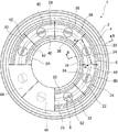
図1は、本実施形態で用いられるガラス成形体の製造装置の構成を示す水平断面図であり、図2は、図1におけるA−A断面図、図3は図1におけるB−B断面図である。図1に示すように、本実施形態のガラス成形体の製造装置1は、有底円筒状に形成された装置筐体2と、装置筐体2内に設けられた回転テーブル4と、回転テーブル4の上方に設けられた水平断面円弧状の内部ケーシング6と、を有する。これら装置筐体2、内部ケーシング6及び回転テーブル4は同心同軸に配置されている。
Hereinafter, an embodiment of a manufacturing apparatus and a manufacturing method of a glass molded body of the present invention will be described in detail with reference to the drawings. In addition, in each embodiment, about the site | part which has a common structure and function, the same code | symbol is attached | subjected and description is abbreviate | omitted.
FIG. 1 is a horizontal sectional view showing a configuration of a glass molded body manufacturing apparatus used in the present embodiment, FIG. 2 is a sectional view taken along line AA in FIG. 1, and FIG. 3 is a sectional view taken along line BB in FIG. It is. As shown in FIG. 1, the glass molded body manufacturing apparatus 1 of the present embodiment includes an
装置筐体2は、上下に略円形の上蓋および底板(図示省略)が取り付けられており、その内部は密閉状態にある。装置筐体2の内部空間は不活性ガス雰囲気とされている。不活性ガスとしては、窒素やアルゴンなどが使用され、酸素濃度が5ppm以下であることが好ましい。なお、このように内部空間を不活性ガス雰囲気とすることで、金型ユニット8の酸化やガラス材料の表面変質を防止できる。
The
上蓋には、成形型を装置内に供給するとともに成形型を装置内から搬出できる搬入・搬出口(図示せず)が形成されていて、その下方の装置内部には搬入・搬出部46が形成されている。なお、本実施形態では、搬入・搬出部46が本発明における供給部と搬出部とを兼ね備えた例を示しているが、搬入部(供給部)と搬出部(搬出口)とを個別に設けてもよい。
The upper lid is formed with a loading / unloading port (not shown) through which the mold can be fed into the apparatus and carried out of the apparatus, and a loading /
回転テーブル4は、回転盤10と、回転盤10の中心に接続された駆動軸(図示せず)と、駆動軸を回転させる、例えば、モータなどの駆動機構(図示せず)と、を備える。回転盤10上には、処理室の数に応じた数(本実施形態では8個)の金型ユニット8が等間隔に配置されている。金型ユニット8は、後述するように、支持台(支持部材)12と、支持台12に載置された複数の(本実施形態では4つ)の成形型52と、により構成される。
The
回転盤10上に配置された金型ユニット8は、回転盤10が回転することにより、内部ケーシング6内の各処理室を間欠的に移送される。本実施形態では、回転テーブル4は、駆動機構が所定時間おきに、間欠的に45度ずつ回転することにより、所定の半径の円周に沿って金型ユニット8を搬送する。この金型ユニット8の搬送される経路が、本発明の搬送経路に相当する。また、回転テーブル4は、各回転動作の間に、予め設定された所定の停止時間にわたり停止する。なお、この回転テーブル4の停止時間は、後述するプレス室26におけるプレス処理に要する時間よりも長くなるように決定されている。
The
内部ケーシング6は、装置筐体2と同心同軸に水平方向に270度の角度範囲にわたって円弧状に延びる内壁6Aと、内壁6Aの半径方向外側に位置し、水平方向に270度の角度範囲にわたって円弧状に延びる外壁6Bと、内壁6Aと外壁6Bの上部の間を塞ぐ天井部と、内壁6Aと外壁6Bの下部の間を塞ぐ底部とを有する。これら内壁6A、外壁6B、天井部6C、及び底部6Dにより、内部ケーシング6内には水平断面が円弧形状の処理空間が形成されている。内部ケーシング6の底部6Dには、金型ユニット8の搬送経路に沿って、円弧状のスリット6Eが形成されている。
The
内部ケーシング6の処理空間は、回転テーブル4の回転方向に45度の角度範囲で6つの室に区切られている。これら6つの室は、金型ユニット8の搬送経路に沿って、第1加熱室20、第2加熱室22、均熱室24、プレス室26、第1徐冷室28、第2徐冷室30の順序で並んでいる。本実施形態における第1加熱室20及び第2加熱室22は本発明の加熱部に相当し、本実施形態の均熱室24は本発明の均熱部に相当し、本実施形態のプレス室26は本発明のプレス部に相当し、本実施形態の第1徐冷室28及び第2徐冷室30は本発明の冷却部に相当する。
The processing space of the
加熱部は、常温に近い温度の金型ユニット8の成形型52とガラス材料60をプレス成形に適した温度まで急速に加熱するための処理部である。本実施形態では、加熱部として、第1加熱室20及び第2加熱室22の2つの加熱室を設け、段階的に金型ユニット8を昇温しているが、処理時間と目的温度に応じて室数を増減してもよい。
The heating unit is a processing unit for rapidly heating the
均熱部は、金型ユニット8をほぼ一定の温度で加熱することにより、成形型52とガラス材料60を均熱化して、プレス成形に適切な温度にするための処理部である。なお、プレス成形に適切な温度は、ガラス硝種や成形体の形状、体積などによって異なるが、概ねガラス材料が106〜1011dPa・sの粘度となる温度であり、ガラス屈伏点温度[Ts]近傍であることが好ましい。
The soaking part is a processing part for heating the
プレス部は、成形型52に荷重を印加することにより、所定の温度まで加熱され軟化したガラス材料を変形させるとともに成形型の成形面の形状を転写して、ガラス成形体を形成する処理部である。プレス部は、後述する図10に示した実施形態のように、複数個所設けてもよい。
The press unit is a processing unit that applies a load to the
冷却部は、プレス部にて形成されたガラス成形体を所定の冷却速度で徐冷する徐冷部を含む処理部である。本実施形態では、冷却部として第1冷却室28及び第2冷却室30の2つの冷却室を設け、段階的に金型ユニット8を徐冷しているが、必要に応じて室数を増減してもよい。
The cooling unit is a processing unit including a slow cooling unit that slowly cools the glass molded body formed by the press unit at a predetermined cooling rate. In this embodiment, two cooling chambers of the
内部ケーシング6の周方向端部及び各室の間には、隣接する処理室を区画するためのシャッター(図示せず)が設けられている。
A shutter (not shown) is provided between the circumferential end of the
第1加熱室20、第2加熱室22、均熱室24、プレス室26、第1徐冷室28、第2徐冷室30の搬送経路の両側部には、それぞれ、ヒータ32、34、36、38、40、42が設けられている。これらヒータ32、34、36、38、40、42は、それぞれ、第1加熱室20、第2加熱室22、均熱室24、プレス室26、第1徐冷室28、第2徐冷室30内を所定の温度になるように加熱している。
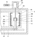
また、図3のみに示すが、均熱室24には、内壁6A及び外壁6Bに沿ってリフレクター36Aが設けられている。リフレクター36Aは、ヒータ32から放射された熱エネルギーを反射するとともに、ヒータ外部へ熱が放出されるのを防ぐ。これにより、熱エネルギーを集中的に成形型に導き、成形型を効率良く加熱することができる。なお、リフレクター36Aは、ヒータ32、34、36、38、40、42が設けられている第1加熱室20、第2加熱室22、均熱室24、プレス室26、第1徐冷室28、第2徐冷室30内にも設置される。
Further, as shown only in FIG. 3, the soaking
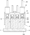
また、図2及び図3に示すように、均熱室24には、複数の遮蔽機構62が設けられている。各遮蔽機構62は、鉛直断面形状がコの字形の遮蔽部64と、遮蔽部64の上部に接続され、上下方向に延びる軸部66と、軸部66を上下させる昇降機構68とにより構成される。遮蔽部64は、例えばニッケル合金やタングステン合金等の耐熱性の高い金属またはセラミックスにより製作される。遮蔽機構62は、金型ユニット8の成形型52のそれぞれに対して金型ユニット8と同数設けられている。また、各遮蔽機構62の昇降機構68は、モータや油圧シリンダ等の駆動機構を有し、制御部70に通信可能に接続されている。制御部70は、昇降機構68を制御し、所望のタイミングで遮蔽部64を下降及び上昇させることができる。
As shown in FIGS. 2 and 3, the soaking
プレス室26の上方の上蓋には、プレス機構(図示せず)が設けられている。プレス機構は、支持台12に載置された複数の成形型それぞれに対応して設けられたモータや油圧シリンダ等の駆動機構を備え、この駆動機構を駆動することにより、駆動機構の一端部に取り付けられたプレスヘッドが、プレス室26内の金型ユニット8の各成形型52を上方から押圧し、ガラス素材に対してプレス処理を行う。なお、回転テーブル4のプレス機構の下方に相当する位置には、プレス機構が成形型を押圧する際に、回転盤10または支持台12を下方から支持する受圧部材を設けておくことが望ましい。
A press mechanism (not shown) is provided on the upper lid above the
図1に示すように、装置筐体2内の搬送経路の第2徐冷室30と、第1加熱室20との間には、急冷部44及び搬入・搬出部46が形成されている。急冷部44は、金型ユニット8を急速に冷却するための領域であり、周囲にヒータが配置されていない。また、搬入・搬出部46は搬入・搬出口を通じて、成形が完了したガラス成形体が収容された成形型と、成形処理が行われていない新たなガラス材料が収容された成形型とを交換するための領域である。なお、搬入・搬出部46には、金型ユニット8を昇降させることができる搬入・搬出機構が設けられており、搬入・搬出機構により金型ユニット8が持ち上げられることにより、搬入・搬出口から成形が完了した成形型52を取り出し、新たな成形型52を支持台12に載置することができる。この搬入・搬出機構が本発明の供給機構及び搬出機構に相当する。
As shown in FIG. 1, a
図2及び図3に示すように、金型ユニット8は、支持台12と、支持台12に載置された複数の(本実施形態では4つ)の成形型52と、により構成される。これら成形型52の材料としては、炭化珪素や超硬合金、窒化珪素等が用いられている。支持台12は、基部12Aと、基部12Aに立設された複数の(本実施形態では4つ)の円柱状の支持部12Bとを備える。各支持部12Bの先端部には、各支持部12Bの先端部の温度を検知可能な温度センサー13が埋設されている。この温度センサー13は制御部70に通信可能に接続されており、各支持部12Bの温度センサー13により測定された温度は、制御部70へと送信される。なお、図2及び図3に示すように、成形型52が支持台12に載置された状態では、各支持部12Bの先端部の温度は成形型52の底部の温度と略等しく、温度センサー13により測定された温度は、成形型52の温度とみなすことができる。
As shown in FIGS. 2 and 3, the
各成形型52は、支持台12のそれぞれの支持部12B上に載置されている。成形型52は、製造すべきガラス成形体の形状に合わせて形成された成形面を有する上型54、下型56と、これら上型54及び下型56の径方向の相互位置を規制する胴型58とを有する。上型54及び下型56の成形面には離型膜が成膜されている。ガラス材料60は、上型54と下型56の間に挟み込まれた状態で配置されている。ガラス材料60をガラス屈伏点温度以上に加熱した状態で、上下型54、56を相対的に近接する方向に加圧することにより、ガラス材料に成形面形状が転写され、所望の形状のガラス成形体(光学素子)にプレス成形することができる。
Each
制御部70には、レンズの成形を開始する前に、予め、遮蔽機構62を停止させた状態で支持台12に成形型52を載置して製造装置1を駆動し、その際、温度センサー13により測定された各金型ユニット8のそれぞれの支持部12Bの先端部における温度履歴が記録されている。後述するように、制御部70は、この記録された各金型ユニット8のそれぞれの支持部12Bの先端部における温度履歴に基づき、各金型ユニット8のそれぞれの金型の温度が実質的に均一になるように、昇降機構68が遮蔽部64を下降及び上昇させるタイミングを制御する。
Before starting the molding of the lens, the
以下、本実施形態のガラス成形体の製造装置1により、ガラス成形体を製造する方法を説明する。なお、以下の説明では、一の金型ユニット8に着目して、ガラス成形体を製造する方法を説明するが、本実施形態のガラス成形体の製造装置1では、各処理室の数に応じた複数の金型ユニット8が回転テーブル4の回転盤10上に45度の等角度範囲で配置される。そして、これら複数の金型ユニット8が回転テーブル4により連続して搬送経路に沿って搬送されて、各処理室で加熱処理、プレス処理、徐冷処理等の処理が並行して行われる。
Hereinafter, a method for manufacturing a glass molded body by the glass molded body manufacturing apparatus 1 of the present embodiment will be described. In the following description, a method of manufacturing a glass molded body will be described by paying attention to one
まず、回転テーブル4が回転し、成形処理が完了したガラス成形体を収容する金型ユニット8が搬入・搬出部46に到達すると、搬入・搬出機構により金型ユニット8が持ち上げられ、搬入・搬出口から、処成形理が完了した4個の成形型52を同時に装置筐体2の外部へ搬出する。そして、これらの成形型52を図示しないロボットハンドで把持して、支持台12の支持部12Bから取り外す。その後、新たなガラス材料60が装填された成形型52を支持台12の支持部12Bにそれぞれ載置する。
First, when the rotary table 4 rotates and the
そして、前回の回転動作の完了から予め設定された回転テーブル4の停止時間(以下、タクトタイムという)が経過すると、内部ケーシング6の周方向端部及び各室の間に設けられたシャッターが開かれ、回転テーブル4が平面視反時計回りに45度回転する。これにより、成形型52は支持台12に保持された状態で、第1加熱室20内に搬送される。この際、支持台12の支持部12Bは、内部ケーシング6の底部に設けられたスリット6E内を通るため、支持部12Bと内部ケーシング6とが干渉することはない。
When a preset stop time (hereinafter referred to as a tact time) of the rotary table 4 has elapsed since the completion of the previous rotation operation, the shutter provided between the circumferential end of the
第1加熱室20に金型ユニット8が搬送されると、金型ユニット8を加熱する第1の加熱ステップが行われる。第1加熱室20内は、搬送経路の両側に設けられたヒータ32により、ガラス屈伏点温度(Ts)と同等もしくはそれ以上の温度に保たれている。そして、第1加熱室20に搬送された金型ユニット8は、ヒータ32により加熱される。
When the
前回の回転テーブル4の回転から予め設定されたタクトタイムが経過すると、内部ケーシング6の周方向端部及び各室の間に設けられたシャッターが開かれ、回転テーブル4が平面視反時計回りに45度回転する。これにより、金型ユニット8は、第2加熱室22内に搬送される。
When a preset tact time elapses from the previous rotation of the
第2加熱室22に金型ユニット8が搬送されると、金型ユニット8の成形型52をガラス屈伏点温度程度まで加熱する第2の加熱ステップが行われる。第2加熱室22内は、ヒータ34によりガラス屈伏点温度と同等もしくはそれ以上の温度に保たれている。これにより、第2加熱室22内に搬送された金型ユニット8内のガラス材料60がガラス屈伏点温度程度に到達するまで加熱される。
When the
前回の回転テーブル4の回転から予め設定されたタクトタイムが経過すると、内部ケーシング6の周方向端部及び各室の間に設けられたシャッターが開かれ、回転テーブル4が平面視反時計回りに45度回転する。これにより、金型ユニット8は、均熱室24内に搬送される。
When a preset tact time elapses from the previous rotation of the
均熱室24に成形型52が搬送されると、成形型52及び内部に収容されたガラス材料60を均熱化する均熱ステップが行われる。均熱室24内は、ヒータ36によりガラス屈伏点温度程度に保たれている。
When the molding die 52 is conveyed to the soaking
本実施形態では、均熱ステップにおいて、成形型52の温度のライン間ばらつき及びユニット間ばらつきを低減するため、遮蔽機構62の遮蔽部64により均熱室24内に位置する金型ユニット8の各成形型52をヒータ36から遮蔽し、さらに、制御部70により各金型ユニット8の複数の成形型52の温度が実質的に均一になるように、複数の遮蔽機構62の遮蔽時間をそれぞれ制御する。具体的には、制御部70に記録された各金型ユニット8のそれぞれの支持部12Bの先端部における温度履歴における均熱室24から搬出される際の温度が、プレス処理における最適温度に対して非常に高い場合には、遮蔽機構62による遮蔽時間を長時間に設定し、プレス処理における最適温度に対してわずかに高い場合には、遮蔽機構62による遮蔽時間を短時間に設定する。
In the present embodiment, in the soaking step, in order to reduce the line-to-line variation and the unit-to-unit variation in the temperature of the
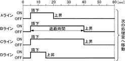
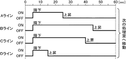
以下、一例をあげて、各金型ユニット8の複数の成形型52の温度が実質的に均一になるように遮蔽機構62による遮蔽時間の制御方法を説明する。なお、以下の説明では、各金型ユニット8における支持台12の複数の支持部12Bを、搬送経路の進行方向前側から後側に向かってそれぞれAライン、Bライン、Cライン、Dラインということとする。また、金型ユニット8については、各処理部に搬送される順番に第1金型ユニット、第2金型ユニット、・・・ということとする。
Hereinafter, as an example, a shielding time control method by the
図4は、第1金型ユニットにおけるA〜Dラインの成形型52に対して、各遮蔽機構62によりヒータ36から遮蔽するタイミングを示すタイムチャートである。また、図5は、第2金型ユニットにおけるA〜Dラインの成形型52に対して、各遮蔽機構62によりヒータ36から遮蔽するタイミングを示すタイムチャートである。これら各遮蔽機構62により成形型52をヒータ36から遮蔽するタイミングは、制御部70に記録された各金型ユニット8のそれぞれの支持部12Bの先端部における温度履歴に基づき決定されている。
FIG. 4 is a time chart showing the timing of shielding from the
本実施形態のように、支持台12に4つの成形型52が取り付けられている場合には、搬送経路の進行方向の中央に位置する成形型52及び支持部12Bは、進行方向の前方側及び後方側の端に位置する成形型52及び支持部12Bに比べて、ヒータ36から大量に輻射熱を受けるとともに、隣接する成形型52及び支持部12Bの熱を受けるため、温度が上昇しやすい。このため、制御部70に記録されている温度履歴は、各金型ユニットに共通してA,Dラインに比べて、B、Cラインの方が高温になる傾向にある。
When the four
さらに、本実施形態のように、均熱室24が第2加熱室22とプレス室26との間に設けられている場合には、プレス室26の方が第2加熱室22に比べて高温に保たれている。このため、制御部70に記録されている温度履歴は、各金型ユニットに共通してAラインの方がDラインに比べて高温になる傾向にある。
Furthermore, when the soaking
したがって、制御部70に記録されている均熱室24から搬出される際の温度も、B、Cラインの成形型52及び支持部12Bの温度が最も高く、次いで、Aラインの成形型52及び支持部12Bの温度が高く、Dラインの成形型52及び支持部12Bの温度が最も低くなる場合が多い。
Therefore, the temperature at the time of carrying out from the soaking | uniform-
このため、本実施形態では、A〜Dラインの遮蔽時間は、各ラインの温度履歴における均熱室24から搬出される際の温度と、プレス処理における最適温度との差に応じて決定する。図4に示すように、第1金型ユニット8において、最も温度が高いB、Cラインでは、均熱室24に金型ユニット8が搬送されてから5秒後から40秒後まで、すなわち、35秒間にわたって遮蔽機構62により成形型52を遮蔽する。また、次いで温度が高いAラインでは、均熱室24に金型ユニット8が搬送されてから、5秒後から20秒後まで、すなわち、15秒間にわたって遮蔽機構62により成形型52を遮蔽する。また、最も温度が低いDラインでは、均熱室24に金型ユニット8が搬送されてから、5秒後から15秒後まで、すなわち、10秒間にわたって、遮蔽機構62により成形型52を遮蔽する。これにより、プレス室26に搬送される際の金型ユニット8における各成形型52のライン間ばらつきは低減されている。
For this reason, in this embodiment, the shielding time of the A to D lines is determined according to the difference between the temperature at the time of carrying out from the soaking
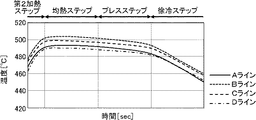
さらに、支持台の製造誤差により、各金型ユニット間で均熱室24から搬出される際の温度にばらつきが生じることがある。本実施形態では、第2金型ユニットのBラインの均熱室24から搬出される際の温度が、第1金型ユニットのBラインの温度よりも高温になっていたとする。このような場合には、第2金型ユニットのBラインの遮蔽機構62による遮蔽時間を第1金型ユニットのBラインに対する遮蔽時間より長くする。すなわち、図5に示すように、Bラインでは、均熱室24に金型ユニット8が搬送されてから、5秒後から45秒後まで、すなわち、40秒間にわたって遮蔽機構62により成形型52を遮蔽することとする。これにより、プレス室26に搬送される際の第1及び第2金型ユニット8における各成形型52のユニット間ばらつきは低減されている。
Further, due to manufacturing errors of the support table, there may be variations in the temperature when the mold units are carried out of the soaking
このようにして、制御部70が、第1〜第8金型ユニット8の各成形型52に対して、それぞれ、適切な遮蔽機構62による遮蔽時間が設定し、これに基づき、制御部70により遮蔽機構62の遮蔽部64を昇降させるタイミングを制御する。これにより、各成形型52は均熱室24において実質的に均一な温度に均熱化される。
In this way, the
なお、上述の通り、本明細書において「温度が実質的に均一」とは、ライン間ばらつき及びユニット間ばらつきにおける最大温度差が10度以下であることをいう。仮に、ライン間ばらつきが10℃以下に抑えられたとしても、ユニット間の温度ばらつきが10℃を超えてしまうと、ガラス素材の粘度で10〜102dPa・sの差が生じてしまう。このような粘度差が生じると、プレス成形品の肉厚が均一にならなかったり、発泡やカン・ワレ、転写不良などの成形不良が発生したりしてしまう。本実施形態によれば、ライン間ばらつき及びユニット間ばらつきにおける最大温度差を10度以下、厳密に制御すれば5℃以下に抑制できるので、成形不良を招くことなく肉厚が均一な成形体を得ることができる。 As described above, “the temperature is substantially uniform” in this specification means that the maximum temperature difference in the line-to-line variation and the unit-to-unit variation is 10 degrees or less. Even if the line-to-line variation is suppressed to 10 ° C. or less, if the temperature variation between the units exceeds 10 ° C., a difference of 10 to 10 2 dPa · s occurs in the viscosity of the glass material. When such a viscosity difference occurs, the thickness of the press-molded product may not be uniform, or molding defects such as foaming, cracks, cracks, and transfer defects may occur. According to this embodiment, the maximum temperature difference in the line-to-line variation and the unit-to-unit variation can be suppressed to 10 ° C. or less and to 5 ° C. or less if strictly controlled. Can be obtained.
前回の回転テーブル4の回転から予め設定されたタクトタイムが経過すると、内部ケーシング6の周方向端部及び各室の間に設けられたシャッターが開かれ、回転テーブル4が平面視反時計回りに45度回転する。これにより、金型ユニット8はプレス室26内に搬送される。
When a preset tact time elapses from the previous rotation of the
プレス室26に金型ユニット8が搬送されると、プレスステップが行われる。プレスステップでは、ヒータ38により金型ユニット8をガラス屈伏点温度程度に保つように加熱しながら、プレス機構により金型ユニット8の成形型52を押圧し、ガラス材料をプレス成形する。プレス荷重は、10〜1000kgf/cm2の範囲内で適宜設定することが好ましい。
When the
そして、プレスステップが完了し、前回の回転テーブル4の回転からタクトタイムが経過すると、内部ケーシング6の周方向端部及び各室の間に設けられたシャッターが開かれ、回転テーブル4が平面視反時計回りに45度回転する。これにより、金型ユニット8の成形型52は、第1徐冷室28内に搬送される。
When the press step is completed and the tact time has elapsed from the previous rotation of the rotary table 4, the shutter provided between the circumferential end of the
第1徐冷室28ではヒータ40により成形型52の温度を調整しながら、ゆっくりと成形型52を冷却する第1の徐冷ステップが行われる。ことのきの冷却速度は、10〜100℃/分の範囲内で適宜設定することが好ましい。
In the first
そして、第1の徐冷ステップが完了し、前回の回転から予め設定されたタクトタイムが経過すると、内部ケーシング6の周方向端部及び各室の間に設けられたシャッターが開かれ、回転テーブル4が平面視反時計回りに45度回転する。これにより、金型ユニット8の成形型52は、第2徐冷室30内に搬送される。
When the first slow cooling step is completed and a preset tact time has elapsed since the previous rotation, the shutter provided between the circumferential end of the
第2徐冷室30ではヒータ42により成形型52の温度を調整しながら、ゆっくりと成形型52を冷却する第2の徐冷ステップが行われる。ことのきの冷却速度は、10〜100℃/分の範囲内で適宜設定することが好ましい。
In the second slow cooling
前回の回転テーブル4の回転からタクトタイムが経過すると、内部ケーシング6の周方向端部及び各室の間に設けられたシャッターが開かれ、回転テーブル4が平面視反時計回りに45度回転する。これにより、金型ユニット8の成形型52は、第2徐冷室30から急冷部44へ搬送される。
When the tact time elapses from the previous rotation of the rotary table 4, the shutter provided between the circumferential end of the
急冷部44に成形型52が搬送されると、急冷ステップが行われる。急冷部44には、ヒータが設置されておらず、装置の周囲と同程度の温度となっている。このため、金型ユニット8及び成形体52の内部のガラス成形体は急速に冷却される。このときの冷却速度は、徐冷ステップでの冷却速度よりも速く、例えば、30〜300℃/分の範囲内で適宜設定することが好ましい。また、必要に応じて金型ユニット8に向けて冷却ガスを吹き付けてもよい。
When the
さらに、前回の回転テーブル4の回転から予め設定されたタクトタイムが経過すると、回転テーブル4が45度回転して、金型ユニット8が搬入・搬出部46へ移送される。
成形処理が完了したガラス成形体を収容する金型ユニット8が搬入・搬出部46に到達すると、昇降機構によって金型ユニット8が上昇し、搬入・搬出口から、成形処理が完了した成形型52を複数個同時に装置筐体2の外部へ搬出する。
以上の工程により、製造装置1によりガラス成形体を連続的に製造することができる。
Further, when a preset tact time elapses from the previous rotation of the rotary table 4, the rotary table 4 rotates 45 degrees and the
When the
Through the above steps, the glass molded body can be continuously produced by the production apparatus 1.
なお、上記の実施形態では、均熱室24のみに遮蔽機構62を設けているが、これに限らず、第1加熱室20、第2加熱室22、第1徐冷室28、及び第2徐冷室30に遮蔽機構62を設け、均熱室24と同様に、遮蔽機構62による遮蔽時間を制御することとしてもよい。この場合には、各室における遮蔽機構の遮蔽時間は、制御部70に記録されている温度履歴における各室から搬出される直前の温度に基づき設定すればよい。
In the above embodiment, the
また、遮蔽機構62を加熱部のみに設けてもよい。加熱部は金型ユニット8を加熱する初期段階にあるため、加熱の初期から金型ユニット8の均熱化を図ることができる。なお、本実施形態のように、複数の加熱室(第1加熱室20、第2加熱室22)が設けられている場合には、遮蔽機構62を何れか一つの加熱室に設けてもよいし、複数の加熱室に設けてもよい。
Further, the
発明者らは、本発明の製造装置によれば、成形型の温度のライン間ばらつき、及びユニット間ばらつきを低減できることを実験により確認した。以下、この実験について説明する。 The inventors have confirmed through experiments that according to the manufacturing apparatus of the present invention, it is possible to reduce the line-to-line variation of the mold and the unit-to-unit variation. Hereinafter, this experiment will be described.
本実験では、遮蔽機構62を駆動した状態及び遮蔽機構62を停止した状態で、それぞれ製造装置1を駆動してガラス成形体を製造し、各金型ユニット8の各ラインA〜Dの温度履歴を測定した。なお、本実験では、均熱室24に加えて、第2加熱室22にも遮蔽機構62を設けている。
In this experiment, in the state where the
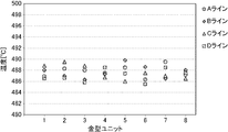
図6は、遮蔽機構62を駆動した状態で製造装置1を駆動してガラス成形体を製造した場合(以下、実施例1という)における、温度センサーにより測定されたA〜Dラインの支持部12Bの先端の温度履歴(成形型の温度履歴に相当する)を示すグラフである。また、図7は、遮蔽機構62を停止させた状態で製造装置1を駆動してガラス成形体を製造した場合(以下、比較例1という)における、温度センサーにより測定されたA〜Dラインの支持部12Bの先端の温度履歴を示すグラフである。なお、これら温度履歴は、第1〜第8金型ユニットの平均の温度履歴を示している。
FIG. 6 shows a supporting
図7に示すように、比較例1では、第2加熱ステップから均熱ステップの間において、上述の通り、B、Cラインの支持部12Bの先端の温度は、A、Dラインに比べて非常に高く上昇している。また、Aラインの支持部12Bの先端の温度は、Dラインに比べて高くなっている。均熱ステップの開始時における最も温度の高いBラインと、最も温度の低いDラインとの温度差は、約15度となっている。そして、この温度差は、プレス工程、及び徐冷工程においてもほとんど解消されることなく残存している。
As shown in FIG. 7, in Comparative Example 1, the temperature at the tip of the
これに対して、図6に示すように、実施例1では、第2の加熱ステップから均熱ステップの間においても、A〜Dラインの温度は実質的に同一な温度履歴を示している。また、均熱ステップの開始時における最も温度の高いBラインと、最も温度の低いDラインとの温度差は約5度と、比較例に比べて非常に小さくなっている。そして、この温度差はプレス工程、及び徐冷工程において、大きくなることはない。 On the other hand, as shown in FIG. 6, in Example 1, the temperatures of the A to D lines show substantially the same temperature history during the second heating step and the soaking step. In addition, the temperature difference between the highest temperature B line and the lowest temperature D line at the start of the soaking step is about 5 degrees, which is very small compared to the comparative example. And this temperature difference does not become large in a press process and a slow cooling process.
また、図8は、遮蔽機構62を駆動した状態で製造装置1を駆動してガラス成形体を製造した場合(以下、実施例2という)であって、均熱室における温度センサーにより測定された第1〜第8の金型ユニットのA〜Dラインの支持部12Bの先端の温度を示すグラフである。また、図9は、遮蔽機構62を停止させた状態で製造装置1を駆動してガラス成形体を製造した場合(以下、比較例2という)であって、均熱室における温度センサーにより測定された第1〜第8の金型ユニットのA〜Dラインの支持部12Bの先端の温度を示すグラフである。なお、図8及び図9における横軸の数字1から8はそれぞれ、第1〜第8金型ユニットに対応している。
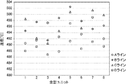
FIG. 8 shows a case where a glass molded body is manufactured by driving the manufacturing apparatus 1 with the
図9に示すように、比較例2では、各金型ユニットにおいて、ライン間で大きな温度ばらつきが生じており、第1〜第8金型ユニットにおけるライン間の温度差は、ほとんどが10℃を超えている。また、比較例2では、均熱室から搬出された際の各金型ユニットの温度にもばらつきが生じている。最も温度の高い第5の金型ユニットのBラインの温度と、最も温度の低い第3の金型ユニットのDラインの温度の差は、15℃以上となっている。 As shown in FIG. 9, in Comparative Example 2, there is a large temperature variation between the lines in each mold unit, and the temperature difference between the lines in the first to eighth mold units is almost 10 ° C. Over. Further, in Comparative Example 2, the temperature of each mold unit when being carried out of the soaking chamber also varies. The difference between the temperature of the B line of the fifth mold unit having the highest temperature and the temperature of the D line of the third mold unit having the lowest temperature is 15 ° C. or more.
これに対して、図8に示すように、実施例2では、各金型ユニットにおけるライン間の温度ばらつきは比較例2に比べて非常に小さくなっており、第1〜第8金型ユニットにおけるライン間の温度差はいずれも5℃以下である。また、実施例2では、均熱室から搬出された際の各金型ユニットの温度のばらつきも非常に小さくなっている。
このように、上記の実験により、本実施形態のガラス成形体の製造装置によれば、各金型ユニットにおけるライン間の温度ばらつきのみならず、金型ユニット間の温度のばらつきをも低減できることが確認された。
On the other hand, as shown in FIG. 8, in Example 2, the temperature variation between the lines in each mold unit is very small compared to Comparative Example 2, and in the first to eighth mold units. The temperature difference between the lines is 5 ° C. or less. Moreover, in Example 2, the dispersion | variation in the temperature of each mold unit at the time of carrying out from a soaking | uniform-heating chamber is also very small.
As described above, according to the glass molded body manufacturing apparatus of the present embodiment, not only the temperature variation between lines in each mold unit but also the temperature variation between mold units can be reduced by the above experiment. confirmed.
以上説明したように、本実施形態によれば、金型ユニット8の支持部12Bに載置される複数の成形型52に対して、それぞれ、遮蔽機構62を設け、制御部によりこれら遮蔽機構62による遮蔽時間を各金型ユニット8のそれぞれの成形型52に対して制御するため、均熱室24から搬出される際の成形型52の温度のばらつき、特に、ユニット間ばらつきを低減することができる。
As described above, according to the present embodiment, the
さらに、本実施形態では、予め、遮蔽機構62を停止させた状態で支持台12に成形型52を載置して製造装置1を駆動し、その際、測定された各金型ユニット8のそれぞれの支持部12Bの先端部における温度履歴が制御部70に記録されている。そして、制御部70はこの温度履歴に基づき、遮蔽機構62による遮蔽時間を制御する。このように、実際に駆動した状態における温度履歴に基づき、遮蔽機構62による遮蔽時間を制御することにより、各成形型52の温度のばらつきをより低減することができる。
Furthermore, in the present embodiment, the
そして、このように各成形型52の温度のばらつきを低減できるため、ガラス成形体の成形精度を向上することができる。 And since the dispersion | variation in the temperature of each shaping | molding die 52 can be reduced in this way, the shaping | molding precision of a glass molded object can be improved.
なお、本実施形態では、回転テーブル4により円形経路に沿って金型ユニット8を搬送することとしているが、これに限らず、アーム等の搬送手段により金型ユニット8を搬送してもよい。また、搬送経路は円形には限られず、直線状としてもよい。
In the present embodiment, the
また、本実施形態では、予め、測定された各金型ユニット8のそれぞれの支持部12Bの先端部における温度履歴に基づき、制御部70は遮蔽機構62による遮蔽時間を制御することとしたが、本発明はこれに限られない。
Further, in the present embodiment, the
例えば、温度センサー13により測定された各金型ユニット8の各支持部12Bの温度に基づき、リアルタイムで遮蔽機構62の遮蔽時間を制御してもよい。このような場合は、例えば、制御部70は、温度センサー13により測定された温度と基準となる温度との差に基づき、遮蔽機構62により遮蔽すべき時間を算出する。そして、制御部70は、算出した遮蔽時間にわたって、遮蔽機構62により成形型52を遮蔽する。このような構成によっても、各金型ユニットのそれぞれの成形型52の温度を実質的に均一にすることができる。
For example, the shielding time of the
また、本実施形態では、第1加熱室20、第2加熱室22、均熱室24、プレス室26、第1徐冷室28、第2徐冷室30が内部ケーシング6内に形成された製造装置1について説明したが、複数のプレス室を備えた製造装置にも本発明を適用することができる。
In the present embodiment, the
図10は、2つのプレス室を備えた製造装置101の構成を示す水平断面図である。同図に示すように、図10に示す製造装置101では、内部ケーシング6内に、加熱室120、第1均熱室122、第1プレス室124、第1徐冷室126、第2均熱室128、第2プレス室130、第2徐冷室132が設けられている。また、加熱室120、第1均熱室122、第1プレス室124、第1徐冷室126、第2均熱室128、第2プレス室130、第2徐冷室132には、それぞれ、ヒータ134、136、138、140、142、144、146が設けられている。
FIG. 10 is a horizontal sectional view showing a configuration of a
このように二つのプレス室を備えた製造装置においても、上記の実施形態と同様に第1及び第2均熱室122、128にそれぞれ遮蔽機構を設けるとよい。
In the manufacturing apparatus including two press chambers as described above, it is preferable to provide a shielding mechanism in each of the first and second soaking
この場合、上記の実施形態と同様に、予め、遮蔽機構62を停止させた状態で支持台に成形型52を載置して製造装置101を駆動し、その際、測定された各金型ユニット8のそれぞれの支持部12Bの先端部における温度履歴に基づき、各均熱室122、128の遮蔽機構62の遮蔽時間を設定してもよい。さらに、以下のようにして各均熱室の遮蔽機構62の遮蔽時間を設定することも可能である。
In this case, similarly to the above-described embodiment, the
まず、予め、第1及び第2均熱室122、128の遮蔽機構62を停止させた状態で支持台12に成形型52を載置して製造装置101を駆動し、各金型ユニット8のそれぞれの支持部12Bの先端部における温度履歴を測定する。そして、この温度履歴に基づき、第1均熱室122の各遮蔽機構62の遮蔽時間を、第1均熱室122から搬出される直前の温度が実質的に均一になるように設定する。
First, with the
次に、第2均熱室128の遮蔽機構62は停止させ、第1均熱室122の遮蔽機構62を起動させた状態で製造装置101を駆動し、各金型ユニット8のそれぞれの支持部12Bの先端部における温度履歴を測定する。なお、この際、第1均熱室122の遮蔽機構62は上記設定した時間だけ、成形型をヒータ136から遮蔽するように駆動させる。
Next, the
そして、このようにして測定された温度履歴に基づき、第2均熱室128の各遮蔽機構62の遮蔽時間を、第2均熱室128から搬出される直前の温度が実質的に均一になるように設定する。
Based on the temperature history thus measured, the shielding time of each
このように、第1及び第2均熱室122、128の遮蔽機構62の遮蔽時間を設定することにより、第1及び第2プレス室124、130に搬入される成形型52の温度をより一層均一にすることができる。
In this way, by setting the shielding time of the
本発明は以上説明したような実施形態に限定されることなく本発明を逸脱しない範囲において種々変更可能であることは言うまでもない。たとえば、本発明における遮蔽部64の形状は断面コの字形状の他に断面U字形状や有底円筒状のものであってもよい。
Needless to say, the present invention is not limited to the embodiments described above, and various modifications can be made without departing from the scope of the present invention. For example, the shape of the shielding
また、上記実施形態では、4本の支持部12Bを有する支持台12に成形型52を4個載置した例を示したが、支持部12Bおよび当該支持部に載置される成形型52の数は、複数であれば2、3、5〜8個のいずれの数量であってもよい。
Moreover, although the example which mounted the four shaping |
以下、本発明を図面を参照しながら、総括する。
本発明のガラス成形体の製造装置1は、図1に示すように、支持台12と、支持台12に搬送経路に沿って並置され内部にガラス材料60を収容した複数の成形型52と、を含む複数の金型ユニット8を、順次、搬送する回転テーブル4と、搬送経路に沿って設けられたガラス材料に加熱処理を行う第1及び第2加熱室20、22、ガラス材料を均熱化する均熱室24、金型に収容されたガラス材料にプレス処理を行い成形体に成形するプレス室26、及び成形体に徐冷処理を行う第1及び第2徐冷室28、30を含む複数の処理部と、複数の処理部の搬送経路に沿って設けられたヒータ32、34、36、38、40、42と、を備える。そして、図2及び図3に示すように、ガラス成形体の製造装置1は、さらに、加熱部(第1加熱室20、第2加熱室22)もしくは均熱室24に設けられ、かつ、複数の成形型52をそれぞれヒータ32から遮蔽することができるように移動可能な複数の遮蔽機構62と、複数の遮蔽機構62により対応する成形型52を遮蔽する遮蔽時間をそれぞれ制御する制御部70と、を備え、制御部70は、各金型ユニット8の複数の成形型52の温度が実質的に均一になるように、複数の遮蔽機構62の遮蔽時間をそれぞれ制御する。
The present invention will be summarized below with reference to the drawings.
As shown in FIG. 1, the glass molded body manufacturing apparatus 1 of the present invention includes a
また、本発明のガラス成形体の製造方法は、上記の製造装置1を用いた方法であって、第1及び第2加熱室20、22において、ガラス材料に加熱処理を行う加熱ステップと、均熱室24において、ガラス材料を均熱化する均熱ステップと、プレス室26においてガラス材料にプレス処理を行い成形体に成形するプレスステップと、第1及び第2徐冷室28、30において、成形体を冷却する冷却ステップと、を備え、加熱ステップもしくは均熱ステップにおいて、各金型ユニット8の複数の金型の温度が実質的に均一になるように、複数の遮蔽機構62の遮蔽時間をそれぞれ制御する。
In addition, the method for producing a glass molded body of the present invention is a method using the production apparatus 1 described above, and includes a heating step in which heat treatment is performed on the glass material in the first and
1、101 製造装置
2 装置筐体
4 回転テーブル
6 内部ケーシング
8 金型ユニット
10 回転盤
12 支持台
20 第1加熱室
22 第2加熱室
24 均熱部
26 プレス室
28 第1徐冷室
30 第2徐冷室
32、34、36、38、40、42 ヒータ
52 成形型
60 ガラス材料
62 遮蔽機構
64 遮蔽部
66 軸部
68 昇降機構
70 制御部
120 加熱室
122 第1均熱室
124 第1プレス室
126 徐冷室
128 第2均熱室
130 第2プレス室
132 徐冷室
134、136、138、140、142、144、146 ヒータ
DESCRIPTION OF SYMBOLS 1,101
Claims (8)
前記搬送経路に沿って設けられた前記ガラス材料に加熱処理を行う加熱部、前記ガラス材料を均熱化する均熱部、前記ガラス材料にプレス処理を行い成形体に成形するプレス部、及び前記成形体に徐冷処理を行う徐冷部を含む複数の処理部と、
前記複数の処理部の前記搬送経路に沿って設けられたヒータと、を備えたガラス成形体の製造装置であって、
前記ガラス成形体の製造装置は、さらに、前記加熱部又は前記均熱部に設けられ、かつ、前記複数の金型をそれぞれヒータから遮蔽することができるように移動可能な複数の遮蔽機構と、
前記複数の遮蔽機構により対応する金型を遮蔽する遮蔽時間をそれぞれ制御する制御部と、を備え、
前記制御部は、前記複数の金型ユニットの各金型の温度が実質的に均一になるように、前記複数の遮蔽機構の前記遮蔽時間をそれぞれ制御する、ガラス成形体の製造装置。 A transport mechanism for sequentially transporting a plurality of mold units including a support member and a plurality of molds juxtaposed along the transport path to the support member and containing a glass material therein;
A heating unit that heat-treats the glass material provided along the transport path, a heat-uniforming unit that soaks the glass material, a press unit that presses the glass material to form a molded body, and the A plurality of processing parts including a slow cooling part for performing a slow cooling process on the molded body;
A heater provided along the transport path of the plurality of processing units, and a glass molded body manufacturing apparatus comprising:
The glass molded body manufacturing apparatus further includes a plurality of shielding mechanisms provided in the heating unit or the soaking unit, and movable so as to shield the plurality of molds from the heaters, respectively.
A control unit for controlling a shielding time for shielding the corresponding mold by the plurality of shielding mechanisms,
The said control part is a manufacturing apparatus of the glass molded object which respectively controls the said shielding time of these shielding mechanisms so that the temperature of each metal mold | die of these mold units may become substantially uniform.
前記制御部は、前記記録された各金型ユニットのそれぞれの金型の温度履歴に応じて、前記複数の遮蔽機構の前記遮蔽時間をそれぞれ制御する、請求項1に記載されたガラス成形体の製造装置。 In the control unit, the temperature history of each mold of each mold unit measured when the glass molded body is manufactured by the glass molded body manufacturing apparatus is recorded,
2. The glass molded body according to claim 1, wherein the control unit controls the shielding time of the plurality of shielding mechanisms according to a temperature history of each die of the recorded die units. manufacturing device.
前記制御部は、前記温度測定部により測定された各金型ユニットのそれぞれの金型の温度に応じて、それぞれの金型の温度が実質的に均一になるように前記複数の遮蔽機構の前記遮蔽時間をそれぞれ制御する、請求項1に記載されたガラス成形体の製造装置。 Furthermore, it has a temperature measuring unit for measuring the temperature of each mold of each mold unit,
The control unit is configured to control the plurality of shielding mechanisms so that the temperatures of the molds are substantially uniform according to the temperature of the molds of the mold units measured by the temperature measurement unit. The manufacturing apparatus of the glass molded object of Claim 1 which controls each shielding time.
前記均熱部は、第1の均熱部及び第2の均熱部を含み、
前記第1の均熱部は、前記第1のプレス部の前記搬送経路の上流側に設けられ、
前記第2の均熱部は、前記第2のプレス部の前記搬送経路の上流側に設けられ、
前記遮蔽機構は、前記第1の均熱部及び第2の均熱部のそれぞれに設けられている、請求項1から4の何れか1項に記載されたガラス成形体の製造装置。 The press part includes a first press part and a second press part,
The soaking part includes a first soaking part and a second soaking part,
The first soaking part is provided on the upstream side of the transport path of the first press part,
The second soaking part is provided on the upstream side of the transport path of the second press part,
The said shielding mechanism is a manufacturing apparatus of the glass molded object as described in any one of Claim 1 to 4 provided in each of said 1st soaking part and 2nd soaking part.
前記搬送経路に沿って設けられた前記ガラス材料に加熱処理を行う加熱部、前記ガラス材料を均熱化する均熱部、前記ガラス材料にプレス処理を行い成形体に成形するプレス部、及び前記成形体に徐冷処理を行う徐冷部を含む複数の処理部と、
前記複数の処理部の前記搬送経路に沿って設けられたヒータと、
前記加熱部又は前記均熱部に設けられ、かつ、前記複数の金型をそれぞれヒータから遮蔽することができるように移動可能な複数の遮蔽機構と、
前記複数の遮蔽機構により対応する金型を遮蔽する遮蔽時間をそれぞれ制御する制御部と、を備えたガラス成形体の製造装置によりガラス成形体を製造する方法であって、
前記方法は、
前記加熱部において、前記ガラス材料に加熱処理を行う加熱ステップと、
前記均熱部において、前記ガラス材料を均熱化する均熱ステップと、
前記プレス部において前記ガラス材料にプレス処理を行い成形体に成形するプレスステップと、
前記徐冷部において、成形体を冷却する冷却ステップと、を備え、
前記加熱ステップ又は前記均熱ステップにおいて、前記複数の金型ユニットの各金型の温度が実質的に均一になるように、前記複数の遮蔽機構の前記遮蔽時間をそれぞれ制御する、ガラス成形体の製造方法。 A transport mechanism that sequentially transports a plurality of mold units including a support member, and a plurality of molds juxtaposed along the transport path to the support member and containing a glass material therein;
A heating unit that heat-treats the glass material provided along the transport path, a heat-uniforming unit that soaks the glass material, a press unit that presses the glass material to form a molded body, and the A plurality of processing parts including a slow cooling part for performing a slow cooling process on the molded body;
A heater provided along the transport path of the plurality of processing units;
A plurality of shielding mechanisms provided in the heating unit or the soaking unit, and movable so as to shield the plurality of molds from the heaters;
A method of manufacturing a glass molded body with a glass molded body manufacturing apparatus comprising: a control unit that controls a shielding time for shielding a corresponding mold by the plurality of shielding mechanisms;
The method
In the heating unit, a heating step of performing a heat treatment on the glass material;
In the soaking part, soaking step for soaking the glass material,
A press step of pressing the glass material in the press section to form a molded body;
A cooling step for cooling the molded body in the slow cooling section,
In the heating step or the soaking step, the shielding time of the plurality of shielding mechanisms is respectively controlled so that the temperatures of the molds of the plurality of mold units become substantially uniform. Production method.
前記加熱ステップ又は前記均熱ステップにおいて、前記制御部により、前記記録された金型ユニットごとのそれぞれの金型の温度履歴に応じて、前記複数の遮蔽機構の前記遮蔽時間をそれぞれ制御する、請求項6に記載されたガラス成形体の製造方法。 In the control unit, the temperature history of each mold is recorded for each mold unit, which is measured when the glass molded body is manufactured by the glass molded body manufacturing apparatus,
In the heating step or the soaking step, the control unit controls the shielding time of the plurality of shielding mechanisms according to the temperature history of each die recorded for each die unit. Item 7. A method for producing a glass molded article according to Item 6.
前記加熱ステップ又は前記均熱ステップにおいて、
前記温度測定部により各金型ユニットにそれぞれの金型の温度を測定し、
前記制御部により、前記温度測定部により測定された各金型ユニットのそれぞれの金型の温度に応じて、前記複数の金型ユニットのそれぞれの金型の温度が実質的に均一になるように前記複数の遮蔽機構の前記遮蔽時間をそれぞれ制御する、請求項6に記載されたガラス成形体の製造方法。 The glass molded body manufacturing apparatus further includes a temperature measuring unit that measures the temperature of each mold for each mold unit,
In the heating step or the soaking step,
Measure the temperature of each mold on each mold unit by the temperature measuring unit,
According to the temperature of each mold of each mold unit measured by the temperature measurement unit, the temperature of each mold of the plurality of mold units is substantially uniform by the control unit. The method for producing a glass molded body according to claim 6, wherein the shielding times of the plurality of shielding mechanisms are respectively controlled.
Priority Applications (3)
| Application Number | Priority Date | Filing Date | Title |
|---|---|---|---|
| JP2013031849A JP5994676B2 (en) | 2013-02-21 | 2013-02-21 | Glass molded body manufacturing apparatus and glass molded body manufacturing method |
| CN201480002727.1A CN104718165B (en) | 2013-02-21 | 2014-02-21 | The manufacture device of glass forming body and the manufacture method of glass forming body |
| PCT/JP2014/054200 WO2014129591A1 (en) | 2013-02-21 | 2014-02-21 | Device for manufacturing molded glass body and method for manufacturing molded glass body |
Applications Claiming Priority (1)
| Application Number | Priority Date | Filing Date | Title |
|---|---|---|---|
| JP2013031849A JP5994676B2 (en) | 2013-02-21 | 2013-02-21 | Glass molded body manufacturing apparatus and glass molded body manufacturing method |
Publications (2)
| Publication Number | Publication Date |
|---|---|
| JP2014162650A JP2014162650A (en) | 2014-09-08 |
| JP5994676B2 true JP5994676B2 (en) | 2016-09-21 |
Family
ID=51391371
Family Applications (1)
| Application Number | Title | Priority Date | Filing Date |
|---|---|---|---|
| JP2013031849A Expired - Fee Related JP5994676B2 (en) | 2013-02-21 | 2013-02-21 | Glass molded body manufacturing apparatus and glass molded body manufacturing method |
Country Status (3)
| Country | Link |
|---|---|
| JP (1) | JP5994676B2 (en) |
| CN (1) | CN104718165B (en) |
| WO (1) | WO2014129591A1 (en) |
Families Citing this family (4)
| Publication number | Priority date | Publication date | Assignee | Title |
|---|---|---|---|---|
| JP6344566B2 (en) * | 2014-09-26 | 2018-06-20 | 日本電気硝子株式会社 | End processing apparatus and end processing method for glass plate |
| JP2017036175A (en) * | 2015-08-10 | 2017-02-16 | Hoya株式会社 | Molding equipment of optical element, and molding method for optical element |
| CN107739145B (en) * | 2017-10-13 | 2023-07-04 | 成都光明光电股份有限公司 | Glass molding device and glass molding method |
| CN113683292A (en) * | 2021-08-25 | 2021-11-23 | 成都光明光电股份有限公司 | Method for manufacturing sample for testing refractive index of optical glass in front of furnace |
Family Cites Families (7)
| Publication number | Priority date | Publication date | Assignee | Title |
|---|---|---|---|---|
| JP2710852B2 (en) * | 1990-03-28 | 1998-02-10 | ホーヤ株式会社 | Apparatus and method for manufacturing glass molded body |
| JP4495842B2 (en) * | 2000-09-01 | 2010-07-07 | Hoya株式会社 | Manufacturing method and manufacturing apparatus for glass molded product, and manufacturing method for glass product |
| JP4538099B2 (en) * | 2005-03-31 | 2010-09-08 | Hoya株式会社 | Mold press molding apparatus and method for manufacturing molded body |
| JP2008001568A (en) * | 2006-06-23 | 2008-01-10 | Fujinon Corp | Glass molding apparatus and glass molding method |
| JP4804280B2 (en) * | 2006-08-31 | 2011-11-02 | Hoya株式会社 | Mold press molding apparatus and method for manufacturing molded body |
| CN101177334B (en) * | 2006-11-06 | 2011-05-04 | 亚洲光学股份有限公司 | glass molding equipment |
| JP2009221077A (en) * | 2008-03-18 | 2009-10-01 | Olympus Corp | Device and method for manufacturing optical element |
-
2013
- 2013-02-21 JP JP2013031849A patent/JP5994676B2/en not_active Expired - Fee Related
-
2014
- 2014-02-21 WO PCT/JP2014/054200 patent/WO2014129591A1/en not_active Ceased
- 2014-02-21 CN CN201480002727.1A patent/CN104718165B/en not_active Expired - Fee Related
Also Published As
| Publication number | Publication date |
|---|---|
| WO2014129591A1 (en) | 2014-08-28 |
| CN104718165B (en) | 2016-12-14 |
| CN104718165A (en) | 2015-06-17 |
| JP2014162650A (en) | 2014-09-08 |
Similar Documents
| Publication | Publication Date | Title |
|---|---|---|
| JP5934801B2 (en) | Molding equipment | |
| JP5994676B2 (en) | Glass molded body manufacturing apparatus and glass molded body manufacturing method | |
| KR101725699B1 (en) | Molded glass body manufacturing method, and molded glass body manufacturing device | |
| US20150232364A1 (en) | Apparatus for manufacturing a glass molding and method for manufacturing a glass molding | |
| JP6047802B2 (en) | Glass molded body manufacturing apparatus and glass molded body manufacturing method | |
| JP6035569B2 (en) | Manufacturing method and manufacturing system of glass molded body | |
| KR101810753B1 (en) | Molded glass body manufacturing method, and molded glass body manufacturing device | |
| JP5690475B2 (en) | Molding apparatus and method for manufacturing molded product | |
| JP4804280B2 (en) | Mold press molding apparatus and method for manufacturing molded body | |
| WO2015146399A1 (en) | Device for producing glass moulded bodies, and method for producing glass moulded bodies | |
| JP2006019565A (en) | Heat treatment apparatus | |
| JP4455963B2 (en) | Molded body manufacturing apparatus and manufacturing method | |
| JP6147571B2 (en) | Glass molded body manufacturing apparatus and glass molded body manufacturing method | |
| JP2007242850A (en) | Semiconductor manufacturing apparatus and semiconductor manufacturing method | |
| EP2915888B1 (en) | Carburizing and quenching facility | |
| JP2022002251A (en) | Heat treatment device | |
| JP2012033805A (en) | Semiconductor manufacturing apparatus and method |
Legal Events
| Date | Code | Title | Description |
|---|---|---|---|
| A621 | Written request for application examination |
Free format text: JAPANESE INTERMEDIATE CODE: A621 Effective date: 20160105 |
|
| TRDD | Decision of grant or rejection written | ||
| A01 | Written decision to grant a patent or to grant a registration (utility model) |
Free format text: JAPANESE INTERMEDIATE CODE: A01 Effective date: 20160801 |
|
| A61 | First payment of annual fees (during grant procedure) |
Free format text: JAPANESE INTERMEDIATE CODE: A61 Effective date: 20160808 |
|
| R150 | Certificate of patent or registration of utility model |
Ref document number: 5994676 Country of ref document: JP Free format text: JAPANESE INTERMEDIATE CODE: R150 |
|
| R250 | Receipt of annual fees |
Free format text: JAPANESE INTERMEDIATE CODE: R250 |
|
| R250 | Receipt of annual fees |
Free format text: JAPANESE INTERMEDIATE CODE: R250 |
|
| R250 | Receipt of annual fees |
Free format text: JAPANESE INTERMEDIATE CODE: R250 |
|
| R250 | Receipt of annual fees |
Free format text: JAPANESE INTERMEDIATE CODE: R250 |
|
| LAPS | Cancellation because of no payment of annual fees |